EP3205044B1 - Rotation-based cipher - Google Patents
Rotation-based cipher Download PDFInfo
- Publication number
- EP3205044B1 EP3205044B1 EP15763170.6A EP15763170A EP3205044B1 EP 3205044 B1 EP3205044 B1 EP 3205044B1 EP 15763170 A EP15763170 A EP 15763170A EP 3205044 B1 EP3205044 B1 EP 3205044B1
- Authority
- EP
- European Patent Office
- Prior art keywords
- value
- state value
- state
- substitution box
- rotated
- Prior art date
- Legal status (The legal status is an assumption and is not a legal conclusion. Google has not performed a legal analysis and makes no representation as to the accuracy of the status listed.)
- Active
Links
- 238000000034 method Methods 0.000 claims description 78
- 238000006467 substitution reaction Methods 0.000 claims description 73
- 230000000873 masking effect Effects 0.000 claims description 12
- 238000012545 processing Methods 0.000 description 67
- 230000006870 function Effects 0.000 description 62
- 230000008569 process Effects 0.000 description 46
- 238000003860 storage Methods 0.000 description 33
- 238000004891 communication Methods 0.000 description 18
- 238000013478 data encryption standard Methods 0.000 description 15
- 238000009792 diffusion process Methods 0.000 description 13
- 238000013461 design Methods 0.000 description 8
- 238000007792 addition Methods 0.000 description 7
- 238000013507 mapping Methods 0.000 description 7
- 241001441724 Tetraodontidae Species 0.000 description 5
- 238000010586 diagram Methods 0.000 description 5
- 230000009466 transformation Effects 0.000 description 5
- 230000011664 signaling Effects 0.000 description 4
- 238000010276 construction Methods 0.000 description 3
- 238000004590 computer program Methods 0.000 description 2
- 238000012986 modification Methods 0.000 description 2
- 230000004048 modification Effects 0.000 description 2
- 230000003287 optical effect Effects 0.000 description 2
- 238000011112 process operation Methods 0.000 description 2
- 230000008901 benefit Effects 0.000 description 1
- 230000005540 biological transmission Effects 0.000 description 1
- 239000004020 conductor Substances 0.000 description 1
- 230000008878 coupling Effects 0.000 description 1
- 238000010168 coupling process Methods 0.000 description 1
- 238000005859 coupling reaction Methods 0.000 description 1
- 125000004122 cyclic group Chemical group 0.000 description 1
- 238000012217 deletion Methods 0.000 description 1
- 230000037430 deletion Effects 0.000 description 1
- 230000009699 differential effect Effects 0.000 description 1
- 230000007274 generation of a signal involved in cell-cell signaling Effects 0.000 description 1
- 238000004519 manufacturing process Methods 0.000 description 1
- 230000004719 natural immunity Effects 0.000 description 1
- 239000005022 packaging material Substances 0.000 description 1
- 230000002093 peripheral effect Effects 0.000 description 1
- 230000001105 regulatory effect Effects 0.000 description 1
- 238000012552 review Methods 0.000 description 1
Images


Classifications
-
- H—ELECTRICITY
- H04—ELECTRIC COMMUNICATION TECHNIQUE
- H04L—TRANSMISSION OF DIGITAL INFORMATION, e.g. TELEGRAPHIC COMMUNICATION
- H04L9/00—Cryptographic mechanisms or cryptographic arrangements for secret or secure communications; Network security protocols
- H04L9/06—Cryptographic mechanisms or cryptographic arrangements for secret or secure communications; Network security protocols the encryption apparatus using shift registers or memories for block-wise or stream coding, e.g. DES systems or RC4; Hash functions; Pseudorandom sequence generators
- H04L9/0618—Block ciphers, i.e. encrypting groups of characters of a plain text message using fixed encryption transformation
-
- H—ELECTRICITY
- H04—ELECTRIC COMMUNICATION TECHNIQUE
- H04L—TRANSMISSION OF DIGITAL INFORMATION, e.g. TELEGRAPHIC COMMUNICATION
- H04L9/00—Cryptographic mechanisms or cryptographic arrangements for secret or secure communications; Network security protocols
- H04L9/002—Countermeasures against attacks on cryptographic mechanisms
- H04L9/003—Countermeasures against attacks on cryptographic mechanisms for power analysis, e.g. differential power analysis [DPA] or simple power analysis [SPA]
-
- H—ELECTRICITY
- H04—ELECTRIC COMMUNICATION TECHNIQUE
- H04L—TRANSMISSION OF DIGITAL INFORMATION, e.g. TELEGRAPHIC COMMUNICATION
- H04L2209/00—Additional information or applications relating to cryptographic mechanisms or cryptographic arrangements for secret or secure communication H04L9/00
- H04L2209/04—Masking or blinding
- H04L2209/046—Masking or blinding of operations, operands or results of the operations
-
- H—ELECTRICITY
- H04—ELECTRIC COMMUNICATION TECHNIQUE
- H04L—TRANSMISSION OF DIGITAL INFORMATION, e.g. TELEGRAPHIC COMMUNICATION
- H04L2209/00—Additional information or applications relating to cryptographic mechanisms or cryptographic arrangements for secret or secure communication H04L9/00
- H04L2209/24—Key scheduling, i.e. generating round keys or sub-keys for block encryption
Definitions
- aspects of the disclosure relate generally to communication, and more specifically, but not exclusively, to a rotation-based cipher.
- a cipher is a cryptographic algorithm used for encryption and/or decryption.
- information commonly referred to as plaintext
- ciphertext On the encryption side, information, commonly referred to as plaintext, is operated on by the cipher to generate encrypted information, commonly referred to as ciphertext.
- encrypted information On the decryption side, encrypted information is operated on by the cipher to recreate the original information (the original plaintext).
- ciphers including so-called block ciphers such as the data encryption standard (DES) cipher and the advanced encryption standard (AES) cipher.
- DES data encryption standard
- AES advanced encryption standard
- a good block cipher is designed around two important principles stated by Claude Shannon: confusion and diffusion.
- Confusion means that the ciphertext should depend on the plaintext and a cryptographic key in a way that is as mathematically complex as possible.
- Diffusion means that small local changes in the plaintext should affect as much of the ciphertext as possible.
- S-Boxes typically map n-bits to n-bits. In some cases (e.g., in designs such as BLOWFISH or CAST), however, S-Boxes map n-bits to m-bits with m larger than n. For example, 8-bit to 32-bit S-Boxes can be employed. In these cases, the S-Boxes also perform part of the role of diffusion, facilitating the design of the cipher. However, in contrast with n-bit to n-bit S-Boxes, such n-bit to m-bit S-Boxes are not bijective functions and they may make the analysis of the cipher more difficult. Also, these S-Boxes are relatively large. For example, in a table-based implementation, BLOWFISH and CAST S-Boxes take up four times as much space as conventional 8-bit S-Boxes.
- United States Patent Application with publication number US 2014/198913 A1 describes techniques for generating cryptographic values.
- Binary input values are rotated by a number of bits equal to the Hamming Weight of the input values.
- a bitwise exclusive OR (XOR) operation is performed on the input and/or output of the rotation operation and a predefined value.
- United States Patent Application with publication number US 2004/184609 A1 describes techniques for generating random sequences for encryption and decryption.
- variable rotation of a value e.g., a table, a string, or some other value
- a subset of a state value is expanded to calculate a rotation distance for such a rotating S-Box, whereby the rotated S-Box or part thereof is then combined with the state value and the new state value is rotated for the next iteration.
- the cipher may be implemented in software (or other code) using conventional instructions, and without the need for large S-Box lookup tables.
- the cipher can be used for encryption (enciphering) of plaintext and decryption (deciphering) of ciphertext.
- the disclosure provides a method for generating a ciphered signal including receiving a first signal; determining a state value based on the first signal; determining a rotation distance based on the state value; rotating a first value based on the rotation distance; combining the rotated first value and the state value; and generating a second signal based on the combination of the rotated first value and the state value.
- Another aspect of the disclosure provides an apparatus configured for generating a ciphered signal including a memory circuit and a processing circuit coupled to the memory circuit.
- the processing circuit is configured to: receive a first signal from the memory circuit; determine a state value based on the first signal; determine a rotation distance based on the state value; rotate a first value based on the rotation distance; combine the rotated first value and the state value; and generate a second signal based on the combination of the rotated first value and the state value.
- the apparatus including means for receiving a first signal; means for determining a state value based on the first signal; means for determining a rotation distance based on the state value; means for rotating a first value based on the rotation distance; means for combining the rotated first value and the state value; and means for generating a second signal based on the combination of the rotated first value and the state value.
- Another aspect of the disclosure provides a non-transitory computer-readable medium storing computer executable code, including code to receive a first signal; determine a state value based on the first signal; determine a rotation distance based on the state value; rotate a first value based on the rotation distance; combine the rotated first value and the state value; and generate a second signal based on the combination of the rotated first value and the state value.
- the rotating and the combining impart nonlinearity on the state value and diffuse the combination within a subsequent instance of the state value.
- the first value is a substitution box value.
- the combining includes masking the rotated first value, and combining the masked rotated first value and the state value.
- the combining includes generating an interim instance of the state value by combining the rotated first value and the state value.
- the generation of the second signal includes generating a subsequent instance of the state value by rotating the interim instance of the state value.
- the interim instance of the state value is rotated by a quantity of bits that is based on a quantity of bits of the first value.
- the generation of the interim instance of the state value includes combining a cryptographic key with a result of the combination of the rotated first value and the state value.
- the determination of the state value includes generating a current instance of the state value by combining a cryptographic key and a previous instance of the state value.
- the determination of the rotation distance is further based a subset of the state value.
- the determination of the rotation distance includes: selecting a subset of bits from the state value, determining a first number that corresponds to the selected subset of bits, determining a second number that corresponds to a quantity of bits of the first value, and multiplying the first number by the second number.
- the determination of the rotation distance includes: masking the state value, and shifting the masked state value.
- the determination of the rotation distance further includes: shifting a second value based on the shifted masked state value, masking the shifted second value, and shifting the masked shifted second value.
- the determination of the state value includes generating a current instance of the state value by rotating a previous instance of the state value.
- the generation of the second signal includes combining a cryptographic key with the combination of the rotated first value with the state value.
- the first value has a value such that the combination of the rotated first value and the state value is bijective.
- the first value is bijective.
- the first signal comprises plaintext
- the second signal comprises an encrypted representation of the plaintext.
- the first signal comprises ciphertext
- the second signal comprises a decrypted representation of the ciphertext.
- the determination of the rotation distance, the rotation of the first value, and the combining of the rotated first value and the state value are performed on an iterative basis to generate the second signal based on the received first signal.
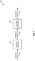
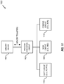
- FIG. 1 is a simplified example of a system 100 that employs a cipher.
- the system 100 includes an encipher component 102 that encrypts plaintext 104, thereby generating ciphertext 106.
- encryption may be used to ensure that the plaintext 104 is secured prior to storage or transmission to another component (not shown).
- the system 100 also includes a decipher component 108 that decrypts the ciphertext 106, thereby recovering the original plaintext 104.
- use of the original plaintext 104 can be limited to authorized users who have been given the capability to decrypt the ciphertext 106.
- a given system can include one or more of the components of FIG. 1 . For example, some systems may only encrypt information, some system may only decrypt information, and some systems may both encrypt and decrypt information.
- nonlinear layer For a block cipher, confusion is typically achieved through the use of nonlinear techniques (commonly referred to as the nonlinear layer).
- S-Boxes can be employed whereby a given input block of information is substituted with another block of information defined by a corresponding one of the S-Boxes.
- diffusion for a block cipher is typically achieved through the use of linear techniques (commonly referred to as the linear layer).
- permutation techniques can be employed to spread information throughout the cipher space. For purposes of illustration, these concepts will be described with reference to examples of a DES block cipher and an AES block cipher.
- FIG. 2 illustrates an example of a DES block cipher 200.
- the input information (plaintext) 202 is operated on by a first linear layer 206 (an expansion permutation), a nonlinear layer 208 (S-Boxes), and a second linear layer 210 (permutation P) to generate output information (ciphertext) 204.
- the nonlinear layer 208 involves substituting S-Box information for the information input into the S-Boxes.
- Each linear layer 206 or 210 (permutation) effectively moves bits around horizontally throughout the cipher space.
- the linear layers 206 and 210 can be thought of as a bit-wise linear transformation which can be represented by a table such as the table 300 of FIG. 3 .
- DES is typically implemented as a series of table lookups. Each lookup into a lookup table will map to a given entry m in the lookup table. In one example, at most four bits are set in any of the entries. In this case, each table lookup for successive DES rounds may involve four 6-bit lookups. Permutation of the input bits across the cipher space is thus achieved through these table lookups.
- FIG. 4 illustrates an example of an AES block cipher 400.
- the input information (plaintext) 402 is operated on by a nonlinear layer 406 (S-Boxes) and a linear layer 408 (shift row and mix column) to generate output information (ciphertext) 404.
- the linear layer 408 involves more than a simple permutation. Rather, bits are mixed in a mathematical manner.
- the linear layer 408 may involve a linear transformation which can be represented by a vector equation.
- AES is also typically implemented as a series of table lookups.
- each table lookup for successive AES rounds may involve shifting a state value, masking off a byte, and running the results through the lookup table.
- the disclosure relates in some aspects to rotation-based ciphers.
- a rotation-based cipher can be efficiently implemented in software (as well as hardware) and may be resistant to cache timing attacks (side-channel resistance).
- such a cipher can be implemented with a very small code footprint. For example, on an Intel® x64 processor, such a cipher can be implemented in less than 100 bytes and/or in less than 25 machine instructions in some implementations. Two examples of rotation-based ciphers are discussed in detail below.
- S 0 , where the four bits of S[15] are the most significant bits of sbox and the four bits of S[0] are the four least significant bits of sbox, then from the value sbox, any value of S[] can be retrieved as: S v sbox > > v * 4 AND 0 x F
- ROR Rotation to the Right.
- state state XOR wide-s-box state AND 0 xF
- state state XOR wide-s-box state AND 0 xF
- the lowest four bits are not modified.
- these bits can be used to compute the value of the wide-s-box and thus revert the last step. Accordingly, to decrypt, the encryption steps can simply be performed in reverse.
- the above cipher is a Target-Heavy Feistel Network as defined in " Unbalanced Feistel Networks and Block Cipher Design", authors Bruce Schneier and John Kelsey, in Proceedings of the Third International Workshop on Fast Software Encryption, Pages 121-144, Springer-Verlag, 1996 .
- the substitution is computed by a rotating S-Box.
- XOR XOR
- another operation can be used to perform the key mixing and/or the mixing of the rotated S-Box.
- integer addition, integer subtraction, or some other mixing (combining) operation may be employed.
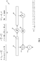
- FIG. 5 is a conceptual representation of a rotation-based cipher 500 in accordance with the teachings herein.
- a subset 502 of the current state 504 is operated on by a ⁇ function 506 to provide an expanded output 508.
- the expanded output 508 is operated on by a ⁇ function 510, whereby the output of the ⁇ function 510 is masked 524 and then XORed 512 with the current state 504.
- the resulting output is then subject to rotation 514 to provide the state 504 for the next round of the cipher 500.
- the operation of the cipher 500 will be described in more detail in the context of an implementation that uses a 64-bit state parameter and 4-bit S-Boxes. It should be understood, however, that the teachings herein are not limited to such an implementation and that other state and S-Box sizes can be used in other implementations.
- the 64-bit state 504 consists of 16 4-bit nibbles. For each round, one nibble is input to the ⁇ function 506.
- the ⁇ function 506 expands the 4-bit nibble of the subset 502 to provide a 64-bit expanded output 508. This operation is shown by the ⁇ description 516 in FIG. 5 .
- an input a of 0x0 maps to ⁇ 0x0, 0x1, 0x2, ... , 0xE, 0xF ⁇
- an input a of 0x1 maps to ⁇ 0x1, 0x2, 0x3, ... , 0xF, 0x0 ⁇ , and so on.
- the expanded output 508 may be represented as (a+15)
- the ⁇ function 506 is a linear layer that provides a diffusion function. Accordingly, relatively wide S-Boxes are created from compact table-based S-Boxes.
- the ⁇ function 510 performs a byte substitution operation as indicated by the ⁇ description 518 in FIG. 5 .
- the ⁇ function 510 is a nonlinear layer that provides a confusion function.
- the S-Box is selected such that S( x ) is bijective.
- the ⁇ function 510 uses a 64-bit table S to perform an S-Box substitution for each nibble of the expanded output 508.
- Fig. 5 illustrates example of such a table 520 where, on a nibble-by-nibble basis, the value S( x ) of a 4-bit S-Box is indicated for a given input x . It should be understood that the teachings herein are not limited to this particular table S and that other table values and/or sizes can be used in other implementations.
- This table lookup is represented mathematically in FIG. 5 by S(x).
- S ( b 0 ) the S-Box substitution for the least significant nibble b 0 of the expanded output 508 is represented by S ( b 0 )
- S ( b 1 ) the S-Box substitution for the next least significant nibble b 1 of the expanded output 508 is represented by S ( b 1 )
- the rotation 514 rotates its input to the right by one nibble (i.e., by four bits).
- the operations are then repeated in the next round until all of the nibbles of the state 504 have been operated on. In practice, these operations are performed multiple times for the entirety of the state 504 to increase the diffusion and confusion characteristics of the ciphertext ultimately output by the cipher 500.
- the cipher 500 can be implemented in software using standard instructions such as rotation, XOR, and bit shifts.
- An example of a set of instructions for a round is set forth in Equation 10.
- ROR is a rotate right operation
- & is an AND operation
- ⁇ is a bit shift left operation
- state corresponds to the state 504
- sbox is the table 520
- MASK corresponds to the mask 524
- key is a cryptographic key.
- the above code is very small: e.g., on the order of 25 instructions (totaling around 100 bytes) on a 64-bit Intel® central processing unit (CPU). It may be seen that there is no need for an explicit diffusion step. Furthermore, this type of design may be cryptanalysed with classical techniques, to provide tight security bounds. In contrast to traditional table lookups, the rotation-based ciphers disclosed herein need not use secret cipher state indexes for data load instructions. Therefore, the data cache footprint of the cipher need not depend on the cipher state. Consequently, this design has natural immunity to cache-timing attacks.
- the inverse of the rotation-based cipher 500 of FIG. 5 performs similar operations as the cipher 500, except in an inverse order.
- such an inverse cipher could be used to decrypt ciphertext generated by the cipher 500.
- the inverse cipher could be used to encrypt plaintext and the cipher 500 used to decrypt the resulting ciphertext.
- another operation such as integer addition or subtraction can be used to perform the key mixing and/or the mixing of the rotated S-Box instead of an XOR operation.
- the inverse of the function is used in the inverse cipher. For example, if addition is used in an encryption function, then subtraction is used in the corresponding place of the decryption function to ensure proper inversion. As another example, if subtraction is used in an encryption function, then addition is used in the corresponding place of the decryption function to ensure proper inversion.
- the inverse cipher can be implemented in software using standard instructions such as rotation, XOR, and bit shifts.
- An example of a set of instructions for a round is set forth in Equation 12.
- ROL is a rotate left operation
- ROR is a rotate right operation
- & is an AND operation
- ⁇ is a bit shift left operation
- state corresponds to the state 504
- sbox is the table 520
- MASK corresponds to the mask 524
- key is a cryptographic key.
- FIG. 6 is a conceptual representation of a rotation-based cipher 600 in accordance with the teachings herein.
- a subset 602 of the current state 604 is operated on by a ⁇ function 606 to provide an expanded output 608.
- the expanded output 608 is operated on by a ⁇ function 610, whereby the output of the ⁇ function 610 is XORed 612 with the current state 604.
- the resulting output is then subject to rotation 614 to provide the state 604 for the next round of the cipher 600.
- the operation of the cipher 600 will be described in more detail in the context of an implementation that uses a 64-bit state parameter and 4-bit S-Boxes. It should be understood, however, that the teachings herein are not limited to such an implementation and that other state and S-Box sizes can be used in other implementations.
- the 64-bit state 604 consists of 16 4-bit nibbles. For each round, one nibble is input to the ⁇ function 606.
- the ⁇ function 606 expands the 4-bit nibble of the subset 602 to provide a 64-bit expanded output 608. This operation is shown by the ⁇ description 616 in FIG. 6 .
- an input a of 0x0 maps to ⁇ 0x0, 0x1, 0x2, ... , 0xE, 0xF ⁇
- an input a of 0x1 maps to ⁇ 0x1, 0x2, 0x3, ... , 0xF, 0x0 ⁇ , and so on.
- the expanded output 608 may be represented as (a+15)
- the ⁇ function 606 is a linear layer that provides a diffusion function. Accordingly, relatively wide S-Boxes are created from compact table-based S-Boxes.
- the ⁇ function 610 performs a byte substitution operation as indicated by the ⁇ description 618 in FIG. 6 .
- the ⁇ function 610 is a nonlinear layer that provides a confusion function.
- the S-Box is selected such that x ⁇ x XOR S(x) is bijective.
- the ⁇ function 610 uses a 64-bit table S to perform an S-Box substitution for each nibble of the expanded output 608.
- Fig. 6 illustrates example of such a table 620 where, on a nibble-by-nibble basis, the value S(x) of a 4-bit S-Box is indicated for a given input x. It should be understood that the teachings herein are not limited to this particular table S and that other table values and/or sizes can be used in other implementations.
- This table lookup is represented mathematically in FIG. 6 by S(x).
- S(x) the S-Box substitution for the least significant nibble b 0 of the expanded output 608
- S( b 1 ) the S-Box substitution for the next least significant nibble b 1 of the expanded output 608
- S(b 1 ) the output of the ⁇ function 610 may be represented as S(b 15 )
- the rotation 614 rotates its input to the right by one nibble (i.e., by four bits).
- the operations are then repeated in the next round until all of the nibbles of the state 604 have been operated on. In practice, these operations are performed multiple times for the entirety of the state 604 to increase the diffusion and confusion characteristics of the ciphertext ultimately output by the cipher 600.
- the cipher 600 can be implemented in software using standard instructions such as rotation, XOR, and bit shifts.
- the above code is very small: e.g., 25 instructions (totaling 100 bytes) on a 64-bit Intel® CPU.
- the above cipher may have faster encryption and better diffusion than the first example cipher. This better diffusion may enable the use of fewer rounds.
- the round function in the decryption is more complex and, hence, is generally slower than the round function in the decryption in the first example cipher.
- the second example cipher is not a Feistel cipher (the "branch" used to determine the S-Box value is also substituted).
- the cipher is not a substitution-permutation network (SPN).
- decryption uses a second table that provides x + S( x ).
- the roles of decryption and encryption can be swapped.
- such a swap may be implemented in a case where decryption occurs on a device that is more computationally limited than the device where encryption occurs.
- the inverse of the rotation-based cipher 600 of FIG. 6 performs similar operations as the cipher 600, except in an inverse order, while using the S-Box T as described above.
- Such an inverse cipher could be used, for example, to decrypt ciphertext generated by the cipher 600.
- the inverse cipher could be used to encrypt plaintext and the cipher 600 used to decrypt the resulting ciphertext.
- the inverse cipher can be implemented in software using standard instructions such as rotation, XOR, and bit shifts.
- the teachings herein are applicable to "wide" S-Boxes, in general, not just the specific example described herein.
- the masking can be used to truncate to smaller sizes.
- the S-Box can be "expanded" to an m-byte wide S-Box by mapping: x -> S[x+m-1]
- the cipher may be relatively secure. This is essentially the same construction as above, but "truncated.”
- mapping may be from 4 bits to n bits.
- mapping can be achieved by mapping: V ⁇ ROT sbox ,4 * v , truncated to n bits
- mapping For a truncation of 4 to 16 bits, the following mapping can be used: V ⁇ ROT sbox ,4 * v & 0 xFFFF , used as a 16 bit word
- mappings would be used for truncations for other values of n.
- applications for the disclosed rotation-based ciphers include ciphers based on 8-bit S-Boxes.
- ciphers based on 8-bit S-Boxes For a 128-bit block cipher with a scheme similar to the "paul_encrypt" cipher above, 16 consecutive values can be used.
- a 271 byte table can be used instead of a 256 byte table.
- indexes are (this is comparable to taking a 256*8 bit "sbox" string and rotating it, and then keeping only a few bits) either interpreted mod 256, or the table itself is actually 259 bytes long and the last three bytes replicate the first three, so that indexes are not to be wrapped modulo 256.
- the same circuit can be reused 4 times either in parallel or serially (e.g., by incrementing the index v each time).
- the Blowfish or CAST S-Boxes are generated as full tables, not a rotating value.
- the Blowfish or CAST S-Boxes may be much larger than S-Boxes employed in accordance with the teachings herein in some implementations.
- a single 64-bit register can be used to represent 16 4-bit entries.
- the different entries are obtained by different rotations of the register.
- substitution is achieved by much more efficient, from a software perspective, rotation operation.
- a DES S-Box S0 can be built using 4 bijective 4-bit S-Boxes.
- the 0-th S-Box is represented by the following: x 0 1 2 4 5 6 7 8 9 A B C D E F S 00 x E 4 D 1 2 F B 8 3 A 6 C 5 9 0 7
- DES involves a memory resident table lookup such as:
- An alternate implementation could use a 124-bit register Z where the 64 least significant bits of Z are Y and the least significant 60 bits of Y are copies in the upper 60 bits of Z.
- S' can be implemented as the 64 least significant bits of Z >> (4x), where ">>" is a simple right shift.
- the above operations can be executed relatively quickly in software.
- Most commodity microprocessors feature a rotation instruction where the rotation distance is taken from a register, i.e., not a constant rotation but a variable rotation.
- the above operations are a simple bit selection.
- the disclosure relates to a processing circuit that performs the operations of Equation 10, Equation 12, Equation 15, Equation 17 or any other operations taught herein.
- FIG. 7 illustrates an example of a processing circuit 702 that operates on plaintext 704 using an equation 706 similar to Equation 10 to generate ciphertext 708.
- FIG. 7 corresponds to encipher (encryption) operations.
- FIG. 8 illustrates an example of a processing circuit 802 that operates on ciphertext 804 using an equation 806 similar to Equation 12 to generate plaintext 808.
- FIG. 8 corresponds to decipher (decryption) operations.
- FIG. 9 illustrates an example of a processing circuit 902 that operates on plaintext 904 using an equation 906 similar to Equation 15 to generate ciphertext 908.
- FIG. 9 corresponds to encipher (encryption) operations.
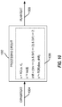
- FIG. 10 illustrates an example of a processing circuit 1002 that operates on ciphertext 1004 using an equation 1006 similar to Equation 17 to generate plaintext 1008.
- FIG. 10 corresponds to decipher (decryption) operations.
- FIG. 11 illustrates a non-limiting example of circuitry 1100 that could be implemented by the processing circuit 702, 802, 902, or 1002.
- a process execution circuit 1102 controls execution of instructions stored in a memory device 1104.
- this circuitry can include a shift circuit 1106 (e.g., that performs a simple shift operation or a rotate operation), a mask circuit 1108 (e.g., that performs an AND operation), and a combine circuit 1110 (e.g., that performs an XOR operation).
- a shift circuit 1106 e.g., that performs a simple shift operation or a rotate operation
- a mask circuit 1108 e.g., that performs an AND operation
- a combine circuit 1110 e.g., that performs an XOR operation.
- FIG. 12 is an illustration of an apparatus 1200 configured to support cipher operations according to one or more aspects of the disclosure.
- the apparatus 1200 includes a communication interface (e.g., at least one transceiver) 1202, a storage medium 1204, a user interface 1206, a memory device 1208, and a processing circuit 1210.
- the signaling bus may include any number of interconnecting buses and bridges depending on the specific application of the processing circuit 1210 and the overall design constraints.
- the signaling bus links together various circuits such that each of the communication interface 1202, the storage medium 1204, the user interface 1206, and the memory device 1208 are coupled to and/or in electrical communication with the processing circuit 1210.
- the signaling bus may also link various other circuits (not shown) such as timing sources, peripherals, voltage regulators, and power management circuits, which are well known in the art, and therefore, will not be described any further.
- the communication interface 1202 may be adapted to facilitate wireless communication of the apparatus 1200.
- the communication interface 1202 may include circuitry and/or code (e.g., instructions) adapted to facilitate the communication of information bi-directionally with respect to one or more communication devices in a network.
- the communication interface 1202 may be coupled to one or more antennas 1212 for wireless communication within a wireless communication system.
- the communication interface 1202 can be configured with one or more standalone receivers and/or transmitters, as well as one or more transceivers.
- the communication interface 1202 includes a transmitter 1214 and a receiver 1216.
- the memory device 1208 may represent one or more memory devices. As indicated, the memory device 1208 may maintain cipher information 1218 along with other information used by the apparatus 1200. In some implementations, the memory device 1208 and the storage medium 1204 are implemented as a common memory component. The memory device 1208 may also be used for storing data that is manipulated by the processing circuit 1210 or some other component of the apparatus 1200.
- the storage medium 1204 may represent one or more computer-readable, machine-readable, and/or processor-readable devices for storing code, such as processor executable code or instructions (e.g., software, firmware), electronic data, databases, or other digital information.
- code such as processor executable code or instructions (e.g., software, firmware), electronic data, databases, or other digital information.
- the storage medium 1204 may also be used for storing data that is manipulated by the processing circuit 1210 when executing code.
- the storage medium 1204 may be any available media that can be accessed by a general purpose or special purpose processor, including portable or fixed storage devices, optical storage devices, and various other mediums capable of storing, containing or carrying code.
- the storage medium 1204 may include a magnetic storage device (e.g., hard disk, floppy disk, magnetic strip), an optical disk (e.g., a compact disc (CD) or a digital versatile disc (DVD)), a smart card, a flash memory device (e.g., a card, a stick, or a key drive), a random access memory (RAM), a read only memory (ROM), a programmable ROM (PROM), an erasable PROM (EPROM), an electrically erasable PROM (EEPROM), a register, a removable disk, and any other suitable medium for storing code that may be accessed and read by a computer.
- a magnetic storage device e.g., hard disk, floppy disk, magnetic strip
- an optical disk e.g., a compact disc (CD) or a digital versatile disc (DVD)
- a smart card e.g., a flash memory device (e.g., a card, a stick, or a key drive
- the storage medium 1204 may be embodied in an article of manufacture (e.g., a computer program product).
- a computer program product may include a computer-readable medium in packaging materials.
- the storage medium 1204 may be a non-transitory (e.g., tangible) storage medium.
- the storage medium 1204 may be coupled to the processing circuit 1210 such that the processing circuit 1210 can read information from, and write information to, the storage medium 1204. That is, the storage medium 1204 can be coupled to the processing circuit 1210 so that the storage medium 1204 is at least accessible by the processing circuit 1210, including examples where at least one storage medium is integral to the processing circuit 1210 and/or examples where at least one storage medium is separate from the processing circuit 1210 (e.g., resident in the apparatus 1200, external to the apparatus 1200, distributed across multiple entities, etc.).
- Code stored by the storage medium 1204 when executed by the processing circuit 1210, causes the processing circuit 1210 to perform one or more of the various functions and/or process operations described herein.
- the storage medium 1204 may include operations configured for regulating operations at one or more hardware blocks of the processing circuit 1210, as well as to utilize the communication interface 1202 for wireless communication utilizing their respective communication protocols.
- the processing circuit 1210 is generally adapted for processing, including the execution of such code stored on the storage medium 1204.
- code or “instructions” shall be construed broadly to include without limitation programming, instructions, instruction sets, data, code, code segments, program code, programs, subprograms, software modules, applications, software applications, software packages, routines, subroutines, objects, executables, threads of execution, procedures, functions, etc., whether referred to as software, firmware, middleware, microcode, hardware description language, or otherwise.
- the processing circuit 1210 is arranged to obtain, process and/or send data, control data access and storage, issue commands, and control other desired operations.
- the processing circuit 1210 may include circuitry configured to implement desired code provided by appropriate media in at least one example.
- the processing circuit 1210 may be implemented as one or more processors, one or more controllers, and/or other structure configured to execute executable code.
- Examples of the processing circuit 1210 may include a general purpose processor, a digital signal processor (DSP), an application specific integrated circuit (ASIC), a field programmable gate array (FPGA) or other programmable logic component, discrete gate or transistor logic, discrete hardware components, or any combination thereof designed to perform the functions described herein.
- DSP digital signal processor
- ASIC application specific integrated circuit
- FPGA field programmable gate array
- a general purpose processor may include a microprocessor, as well as any conventional processor, controller, microcontroller, or state machine.
- the processing circuit 1210 may also be implemented as a combination of computing components, such as a combination of a DSP and a microprocessor, a number of microprocessors, one or more microprocessors in conjunction with a DSP core, an ASIC and a microprocessor, or any other number of varying configurations. These examples of the processing circuit 1210 are for illustration and other suitable configurations within the scope of the disclosure are also contemplated.
- the processing circuit 1210 may be adapted to perform any or all of the features, processes, functions, operations and/or routines for any or all of the apparatuses described herein.
- the term "adapted" in relation to the processing circuit 1210 may refer to the processing circuit 1210 being one or more of configured, employed, implemented, and/or programmed to perform a particular process, function, operation and/or routine according to various features described herein.
- the processing circuit 1210 may include one or more of a circuit/module for receiving a signal 1220, a circuit/module for determining a state value 1222, a circuit/module for determining a rotation distance 1224, a circuit/module for rotating a substitution box value 1226, a circuit/module for combining 1228, and a circuit/module for generating a signal 1230.
- the circuit/module for receiving a signal 1220 may include circuitry and/or code (e.g., code for receiving a signal 1232 stored on the storage medium 1204) adapted to perform several functions relating to, for example, receiving plaintext, cipher text, or other information in the form of an electrical signal. Initially, the circuit/module for receiving a signal 1220 obtains received information. For example, the circuit/module for receiving a signal 1220 may obtain this data directly from a component of the apparatus (e.g., the receiver 1216, the memory device 1208, or some other component). In some implementations, the circuit/module for receiving a signal 1220 identifies a memory location of a value in the memory device 1208 and invokes a read of that location.
- code e.g., code for receiving a signal 1232 stored on the storage medium 1204
- the circuit/module for receiving a signal 1220 processes the received information.
- the circuit/module for receiving a signal 1220 then outputs the received information (e.g., stores the information in the memory device 1208 or sends the information to another component of the apparatus 1200).
- the circuit/module for determining a state value 1222 may include circuitry and/or code (e.g., code for determining a state value 1234 stored on the storage medium 1204) adapted to perform several functions relating to, for example, obtaining a state value to be used for a given instance of an iterative cipher. In some implementations, an initial state value is combined with a cryptographic key.
- the circuit/module for determining a state value 1222 enables the value to be operated on by a cipher (e.g., stores the indication in the memory device 1208 or sends the indication to another component of the apparatus 1200).
- the circuit/module for determining a rotation distance 1224 may include circuitry and/or code (e.g., code for determining a rotation distance 1236 stored on the storage medium 1204) adapted to perform several functions relating to, for example, calculating a rotation value (i.e., a number) from the state value determined by the circuit/module for determining a state value 1222. In some implementations, this involves obtaining (e.g., masking off) a subset of the state value, expanding the subset, and determining at least one rotation value (e.g., a set of rotation values) from the expanded value. Upon obtaining the state value, the circuit/module for determining a rotation distance 1224 passes the value to another operation (e.g., stores the indication in the memory device 1208 or sends the indication to another component of the apparatus 1200).
- code e.g., code for determining a rotation distance 1236 stored on the storage medium 1204
- the circuit/module for rotating a substitution box value 1226 may include circuitry and/or code (e.g., code for rotating a substitution box value 1238 stored on the storage medium 1204) adapted to perform several functions relating to, for example, performing a rotation operation.
- the circuit/module for rotating a substitution box value 1226 obtains the rotation distance and the substitution box value, and rotates (e.g., shifts) the substitution box value by the desired number of bits.
- the circuit/module for rotating a substitution box value 1226 then outputs the rotated value (e.g., stores the value in the memory device 1208 or sends the indication to another component of the apparatus 1200).
- the circuit/module for combining 1228 may include circuitry and/or code (e.g., code for combining 1240 stored on the storage medium 1204) adapted to perform several functions relating to, for example, combining a rotated substitution box value with a state value.
- the circuit/module for combining 1228 obtains the rotated substitution box value and the state value, and combines (e.g., XORs) the two values.
- the circuit/module for combining 1228 then outputs the combined value (e.g., stores the value in the memory device 1208 or sends the indication to another component of the apparatus 1200).
- the circuit/module for generating a signal 1230 may include circuitry and/or code (e.g., code for generating a signal 1242 stored on the storage medium 1204) adapted to perform several functions relating to, for example, generating a subsequent or a final iteration of a state value.
- the circuit/module for generating a signal 1230 combines the iteration of the state value with a cryptographic key.
- the circuit/module for generating a signal 1230 then generates a signal corresponding to the value and outputs the signal (e.g., stores the value in the memory device 1208 or sends the indication to another component of the apparatus 1200).
- code stored by the storage medium 1204 when executed by the processing circuit 1210, causes the processing circuit 1210 to perform one or more of the various functions and/or process operations described herein.
- the storage medium 1204 may include one or more of the code for receiving a signal 1232, the code for determining a state value 1234, the code for determining a rotation distance 1236, the code for rotating a substitution box value 1238, the code for combining 1240, and the code for generating a signal 1242.
- FIG. 13 illustrates a cipher process 1300 in accordance with some aspects of the disclosure.
- the process 1300 may take place within a processing circuit (e.g., the processing circuit 702 of FIG. 7 , the processing circuit 802 of FIG. 8 , the processing circuit 902 of FIG. 9 , the processing circuit 1002 of FIG. 10 , or the processing circuit 1210 of FIG. 12 ), which may be located in an electronic device, a transceiver, or some other suitable apparatus.
- a processing circuit e.g., the processing circuit 702 of FIG. 7 , the processing circuit 802 of FIG. 8 , the processing circuit 902 of FIG. 9 , the processing circuit 1002 of FIG. 10 , or the processing circuit 1210 of FIG. 12
- the process 1300 may be implemented by any suitable apparatus capable of supporting cipher operations.
- a processing circuit may retrieve data (e.g., plaintext or ciphertext) from a memory device.
- data e.g., plaintext or ciphertext
- a state value is determined based on the first signal.
- information e.g., plaintext or ciphertext
- a cryptographic key prior to the operations of blocks 1306 - 1312.
- the determination of the state value at block 1304 involves generating a current instance of the state value by combining a cryptographic key and a previous instance of the state value.
- combining may include an XOR operation, an addition operation, a subtraction operation, some other operation, or a combination of one or more of these operations.
- information e.g., plaintext or ciphertext
- information is rotated prior to the operations of blocks 1306 - 1312.
- the determination of the state value at block 1304 involves generating a current instance of the state value by rotating a previous instance of the state value.
- a rotation distance is determined based on the state value.
- the operations of block 1306 may correspond to determining the amount of the rotate right (ROR) to be performed at the second instruction of Equation 10, at the second instruction of Equation 12, at the second instruction of Equation 15, at the second and third instructions of Equation 17, by the ⁇ function 510 of FIG. 5 , or by the ⁇ function 610 of FIG. 66.
- the determination of the rotation distance of block 1308 may be performed in different ways in different implementations.
- the determination of the rotation distance may be based a subset of the state value.
- the determination of the rotation distance may include: selecting a subset of bits from the state value; determining a first number that corresponds to the selected subset of bits; determining a second number that corresponds to a quantity of bits of the substitution box value; and multiplying the first number by the second number.
- the determination of the rotation distance may include: masking the state value, and shifting the masked state value.
- the determination of the rotation distance may further include: shifting a second value based on the shifted masked state value, masking the shifted second value, and shifting the masked shifted second value.
- a first value (e.g., a substitution box value) is rotated based on the rotation distance determined at block 1306.
- the first value may be a substitution box value (e.g., a value from an S-Box, a value derived from an S-Box, or a value used to generate an S-Box).
- the first value may have a value such that the combination of the rotated substitution box value and the state value is bijective. In some aspects, the first value may be bijective.
- the rotating of block 1308 may be performed in different ways in different implementations.
- the rotating of block 1308 may involve a rotation instruction.
- the rotated first value is combined with the state value.
- the rotating of block 1308 and the combining of block 1310 may impart nonlinearity on the state value and diffuse the combination within a subsequent instance of the state value.
- the rotating of block 1308 and the combining of block 1310 may be combined in a single instruction (e.g., as in Equation 10, 12, 15, or 17) in some implementations.
- the combining of block 1310 may be performed in different ways in different implementations.
- the combining may include masking the rotated first value, and combining the masked rotated first value and the state value.
- the combining may include generating an interim instance of the state value by combining the rotated first value and the state value.
- combining may include an XOR operation, an addition operation, a subtraction operation, some other operation, or a combination of one or more of these operations.
- a second signal is generated based on the combination of the rotated first value and the state value from block 1310.
- a processing circuit may store the resulting state value in a memory device.
- the signal generation of block 1312 may be performed in different ways in different implementations.
- the generation of the second signal may include generating a subsequent instance of the state value by rotating the interim instance of the state value.
- the interim instance of the state value may be rotated by a quantity of bits that is based on a quantity of bits of the substitution box value.
- the generation of the interim instance of the state value may include combining a cryptographic key with the combination of the rotated first value and the state value.
- the operations of block 1306 - 1312 may be repeated until a desired level of diffusion and confusion is imparted on the state value.
- the determination of the rotation distance, the rotation of the substitution box value, and the combining of the rotated substitution box value and the state value may be performed on an iterative basis to generate the second signal based on the received first signal.
- ROR is a rotate right operation
- & is an AND operation
- ⁇ is a bit shift left operation
- s corresponds to instances of the state value
- M1 is a first mask value (e
- ROL is a rotate left operation
- ROR is a rotate right operation
- & an AND operation
- ⁇ is a bit shift left operation
- s corresponds
- ROR is a rotate right operation
- & an AND operation
- ⁇ is a bit shift left operation
- s corresponds to instances of the state value
- M1 is a mask value (e.g., 0xF)
- S1 is a
- FIG. 14 illustrates another example of a cipher process 1400 in accordance with some aspects of the disclosure.
- the process 1400 may take place within a processing circuit (e.g., the processing circuit 702 of FIG. 7 , the processing circuit 902 of FIG. 9 , or the processing circuit 1210 of FIG. 12 ), which may be located in an electronic device, a transceiver, or some other suitable apparatus.
- a processing circuit e.g., the processing circuit 702 of FIG. 7 , the processing circuit 902 of FIG. 9 , or the processing circuit 1210 of FIG. 12
- the process 1400 may be implemented by any suitable apparatus capable of supporting cipher operations.
- a value for a first parameter is received.
- a cipher device may receive plaintext that is to be encrypted.
- a cipher device may receive ciphertext that is to be decrypted.
- This plaintext or ciphertext may thus serve as the first instance of a state parameter (first parameter) used in the cipher process 1400.
- plaintext or ciphertext may be XORed with a cryptographic key to provide the first instance of the state parameter for a given round (e.g., as in the above "paul" ciphers).
- a second parameter is rotated based on a subset of a current instance of the first parameter.
- an S-Box vector (second parameter) can be rotated by an amount that is based on a nibble of the state parameter.
- the rotation of the second parameter based on a subset of a current instance of the first parameter includes: selecting a subset of bits from the current instance of the first parameter; and multiplying the selected subset of bits by a number (e.g., four) that corresponds to a quantity of bits (e.g., four bits) in a given one of the substitution boxes.
- an interim instance of the first parameter is generated by combining the result of block 1404 and the current instance of the first parameter.
- a new value for the state parameter can be generated by combining the S-Box vector and the state parameter. It should be appreciated that the operations of blocks 1404 - 1406 can be performed, for example, at the second instruction of Equation 10, or at the second instruction of Equation 15.
- the generation of the interim instance of the first parameter also includes combining a cryptographic key and this new value of the state parameter (e.g., see Equation 10).
- This aspect of the operations of block 1406 can be performed, for example, as shown at the second instruction line of equation 706 of FIG. 7 or the second instruction line of equation 906 of FIG. 9 .
- a subsequent instance of the first parameter is generated by rotating the interim instance of the first parameter.
- the new value for the state parameter generated at block 1406 can be rotated by a defined number of bits.
- the interim instance of the first parameter is rotated by a quantity of bits corresponding to a quantity of bits (e.g., four bits) in a given one of the substitution boxes.
- the operations of block 1406 can be performed, for example, at the third instruction of Equation 10, or at the third instruction of Equation 15.
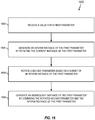
- FIG. 15 illustrates a cipher process 1500 that provides a more detailed example of the cipher process 1300 of FIG. 13 in accordance with some aspects of the disclosure.
- the process 1500 may take place within a processing circuit (e.g., the processing circuit 702 of FIG. 7 , the processing circuit 902 of FIG. 9 , or the processing circuit 1210 of FIG. 12 ), which may be located in an electronic device, a transceiver, or some other suitable apparatus.
- the process 1500 may be implemented by any suitable apparatus capable of supporting cipher operations.
- a state parameter is initialized.
- the operations of block 1502 may correspond to the operations of block 1302 of FIG. 13 whereby an initial value for the state parameter is based on an input value (e.g., plaintext or ciphertext).
- the result of block 1504 is multiplied by a defined value (e.g., four) to generate a first rotation value. As shown in Equations 10 and 12, this may be achieved shifting the result of the AND operation to the left by two bits.
- an S-Box value (e.g., vector) is rotated to the right by the number of bits specified by the first rotation value generated at block 1506.
- the result of block 1508 is combined (e.g., XORed) with the state parameter to provide an updated value for the state parameter. It should be appreciated that the operations of blocks 1504 - 1510 can be performed, for example, at the second instruction line of Equation 10 or Equation 15.
- the result of block 1510 is combined (e.g., XORed) with a cryptographic key value to provide another updated value for the state parameter.
- the operations of block 1512 can be performed, for example, as shown at the second instruction line of equation 706 of FIG. 7 or the second instruction line of equation 906 of FIG. 9 .
- the state parameter may be XORed with a key value at other parts of the cipher.
- the result of block 1512 is rotated to the right according to a second rotation value to provide the next iteration of the state parameter for the next round of the cipher.
- the operations of block 1514 can be performed, for example, at the third instruction line of Equation 10 or 15.
- blocks 1504 to 1514 are performed on an iterative basis to generate an encrypted value (ciphertext) based on the input value (plaintext) or to generate a decrypted value (plaintext) based on the input value (ciphertext).
- FIG. 16 illustrates another cipher process 1600 in accordance with some aspects of the disclosure.
- the process 1600 is the inverse of the process 1400 of FIG. 14 .
- the process 1400 could be used for encryption and the process 1600 used for decryption, or vice versa.
- the process 1600 may take place within a processing circuit (e.g., the processing circuit 802 of FIG. 8 , processing circuit 1002 of FIG. 10 , or the processing circuit 1210 of FIG. 12 ), which may be located in an electronic device, a transceiver, or some other suitable apparatus.
- a processing circuit e.g., the processing circuit 802 of FIG. 8 , processing circuit 1002 of FIG. 10 , or the processing circuit 1210 of FIG. 12
- the process 1600 may be implemented by any suitable apparatus capable of supporting cipher operations.
- a value for a first parameter is received.
- a cipher device may receive ciphertext that is to be decrypted.
- a cipher device may receive plaintext that is to be encrypted. This plaintext or ciphertext may thus serve as the first instance of a state parameter (first parameter) used in the cipher process 1600.
- plaintext or ciphertext may be XORed with a cryptographic key to provide the first instance of the state parameter (e.g., as in a "paul" cipher above).
- an interim instance of the first parameter is generated by rotating the current instance of the first parameter.
- the new current value of the state parameter can be rotated by a defined number of bits.
- the interim instance of the first parameter is rotated by a quantity of bits corresponding to a quantity of bits (e.g., four bits) in a given one of the substitution boxes.
- the operations of block 1606 can be performed, for example, at the first instruction line of Equation 12 or 17.
- the generation of the interim instance of the first parameter also includes combining a cryptographic key and this new value of the state parameter (e.g., see Equation 12).
- This aspect of the operations of block 1604 can be performed, for example, as shown at the second instruction line of equation 806 of FIG. 8 or the second instruction line of equation 1006 of FIG. 10 .
- a second parameter is rotated based on a subset of an interim instance of the first parameter.
- an S-Box vector (second parameter) can be rotated by an amount that is based on a nibble of the state parameter.
- the rotation of the second parameter based on a subset of a current instance of the first parameter includes: selecting a subset of bits from the current instance of the first parameter; and multiplying the selected subset of bits by a number (e.g., four) that corresponds to a quantity of bits (e.g., four bits) in a given one of the substitution boxes.
- a subsequent instance of the first parameter is generated by combining the result of block 1606 and the interim instance of the first parameter.
- a new value for the state parameter can be generated by combining the S-Box vector and the state parameter. It should be appreciated that the operations of blocks 1606 - 1608 can be performed, for example, at the second instruction line of Equation 12 or the third instruction line of Equation 17.
- FIG. 17 illustrates a cipher process 1700 that provides a more detailed example of the cipher process 1600 of FIG. 16 in accordance with some aspects of the disclosure.
- the process 1700 is the inverse of the process 1500 of FIG. 15 .
- the process 1500 could be used for encryption and the process 1700 used for decryption, or vice versa.
- the process 1700 may take place within a processing circuit (e.g., the processing circuit 802 of FIG. 8 , the processing circuit 1002 of FIG. 10 , or the processing circuit 1210 of FIG. 12 ), which may be located in an electronic device, a transceiver, or some other suitable apparatus.
- a processing circuit e.g., the processing circuit 802 of FIG. 8 , the processing circuit 1002 of FIG. 10 , or the processing circuit 1210 of FIG. 12
- the process 1700 may be implemented by any suitable apparatus capable of supporting cipher operations.
- a state parameter is initialized.
- the operations of block 1702 may correspond to the operations of block 1302 of FIG. 13 whereby an initial value for the state parameter is based on an input value (e.g., plaintext or ciphertext).
- the state parameter is rotated to the left according to a first rotation value to provide the next iteration of the state parameter for the next round of the cipher.
- the operations of block 1704 can be performed by the first instruction line of Equation 12 or 17.
- the result of block 1704 is combined (e.g., XORed) with a cryptographic key value to provide another updated value for the state parameter.
- the operations of block 1706 can be performed, for example, at the second instruction line of equation 806 of FIG. 8 or equation 1006 of FIG. 10 .
- the state parameter may be XORed with a key value at other parts of the cipher.
- the result of block 1708 is multiplied by four to generate a second rotation value. As shown in Equations 12 and 17, this may be achieved shifting the result of the AND operation to the left by two bits.
- an S-Box vector is rotated to the right by the number of bits specified by the second rotation value generated at block 1710.
- the result of block 1712 is combined (e.g., XORed) with the state parameter to provide an updated value for the state parameter. It should be appreciated that the operations of blocks 1708 - 1714 can be performed by the second instruction line of Equation 12 or the second and third instruction lines of Equation 17.
- blocks 1704 to 1714 are performed on an iterative basis to generate a decrypted value (plaintext) based on the input value (ciphertext) or to generate an encrypted value (ciphertext) based on the input value (plaintext).
- One or more of the components, steps, features and/or functions illustrated in the figures may be rearranged and/or combined into a single component, step, feature or function or embodied in several components, steps, or functions. Additional elements, components, steps, and/or functions may also be added without departing from novel features disclosed herein.
- the apparatus, devices, and/or components illustrated in the figures may be configured to perform one or more of the methods, features, or steps described herein.
- the novel algorithms described herein may also be efficiently implemented in software and/or embedded in hardware.
- a process that is depicted as a flowchart, a flow diagram, a structure diagram, or a block diagram. Although a flowchart may describe the operations as a sequential process, many of the operations can be performed in parallel or concurrently. In addition, the order of the operations may be re-arranged. A process is terminated when its operations are completed. In some aspects, a process may correspond to a method, a function, a procedure, a subroutine, a subprogram, etc. When a process corresponds to a function, its termination corresponds to a return of the function to the calling function or the main function.
- One or more of the various methods described herein may be partially or fully implemented by code (e.g., instructions and/or data) that may be stored in a machine-readable, computer-readable, and/or processor-readable storage medium, and executed by one or more processors, machines and/or devices.
- code e.g., instructions and/or data
- the word "exemplary” is used to mean “serving as an example, instance, or illustration.” Any implementation or aspect described herein as “exemplary” is not necessarily to be construed as preferred or advantageous over other aspects of the disclosure. Likewise, the term “aspects” does not require that all aspects of the disclosure include the discussed feature, advantage or mode of operation.
- the term “coupled” is used herein to refer to the direct or indirect coupling between two objects. For example, if object A physically touches object B, and object B touches object C, then objects A and C may still be considered coupled to one another-even if they do not directly physically touch each other. For instance, a first die may be coupled to a second die in a package even though the first die is never directly physically in contact with the second die.
- circuit and circuitry are used broadly, and intended to include both hardware implementations of electrical devices and conductors that, when connected and configured, enable the performance of the functions described in the disclosure, without limitation as to the type of electronic circuits, as well as software implementations of information and instructions that, when executed by a processor, enable the performance of the functions described in the disclosure.
- determining encompasses a wide variety of actions. For example, “determining” may include calculating, computing, processing, deriving, investigating, looking up (e.g., looking up in a table, a database or another data structure), ascertaining, and the like. Also, “determining” may include receiving (e.g., receiving information), accessing (e.g., accessing data in a memory), and the like. Also, “determining” may include resolving, selecting, choosing, establishing, and the like.
Landscapes
- Engineering & Computer Science (AREA)
- Computer Security & Cryptography (AREA)
- Computer Networks & Wireless Communication (AREA)
- Signal Processing (AREA)
- Storage Device Security (AREA)
- Executing Machine-Instructions (AREA)
Description
- Aspects of the disclosure relate generally to communication, and more specifically, but not exclusively, to a rotation-based cipher.
- A cipher is a cryptographic algorithm used for encryption and/or decryption. On the encryption side, information, commonly referred to as plaintext, is operated on by the cipher to generate encrypted information, commonly referred to as ciphertext. On the decryption side, encrypted information is operated on by the cipher to recreate the original information (the original plaintext). There are various types of ciphers, including so-called block ciphers such as the data encryption standard (DES) cipher and the advanced encryption standard (AES) cipher.
- A good block cipher is designed around two important principles stated by Claude Shannon: confusion and diffusion. Confusion means that the ciphertext should depend on the plaintext and a cryptographic key in a way that is as mathematically complex as possible. Diffusion means that small local changes in the plaintext should affect as much of the ciphertext as possible. These goals are typically achieved through the use of simple building blocks that achieve confusion for a small number of bits (e.g., so-called substitution boxes (S-Boxes)), normally placed in a wide array called the substitution layer, and by linear layers that intermix the outputs of the substitution layer.
- S-Boxes typically map n-bits to n-bits. In some cases (e.g., in designs such as BLOWFISH or CAST), however, S-Boxes map n-bits to m-bits with m larger than n. For example, 8-bit to 32-bit S-Boxes can be employed. In these cases, the S-Boxes also perform part of the role of diffusion, facilitating the design of the cipher. However, in contrast with n-bit to n-bit S-Boxes, such n-bit to m-bit S-Boxes are not bijective functions and they may make the analysis of the cipher more difficult. Also, these S-Boxes are relatively large. For example, in a table-based implementation, BLOWFISH and CAST S-Boxes take up four times as much space as conventional 8-bit S-Boxes.
- Moreover, these table-based implementations are inherently susceptible to cache-timing attacks. A cipher's internal state is intended to be secret. However, parts of the state are used as indexes or offsets to the S-Box lookup tables. Latency associated with performing loads from the tables depends on the availability in the processor's data cache. By measuring this latency, an attacker can exploit this dependency to recover the internal cipher state and, eventually, the cryptographic key used by the cipher.
- United States Patent Application with publication number
US 2014/198913 A1 describes techniques for generating cryptographic values. Binary input values are rotated by a number of bits equal to the Hamming Weight of the input values. A bitwise exclusive OR (XOR) operation is performed on the input and/or output of the rotation operation and a predefined value.
United States Patent Application with publication numberUS 2004/184609 A1 describes techniques for generating random sequences for encryption and decryption. - The following presents a simplified summary of some aspects of the disclosure to provide a basic understanding of such aspects. This summary is not an extensive overview of all contemplated features of the disclosure, and is intended neither to identify key or critical elements of all aspects of the disclosure nor to delineate the scope of any or all aspects of the disclosure. Its sole purpose is to present various concepts of some aspects of the disclosure in a simplified form as a prelude to the more detailed description that is presented later.
- Various aspects of the present disclosure provide for a cipher where variable rotation of a value (e.g., a table, a string, or some other value) is employed as a large S-Box to achieve both confusion and diffusion. In some aspects, for each iteration of an iterative cipher, a subset of a state value is expanded to calculate a rotation distance for such a rotating S-Box, whereby the rotated S-Box or part thereof is then combined with the state value and the new state value is rotated for the next iteration. Advantageously, the cipher may be implemented in software (or other code) using conventional instructions, and without the need for large S-Box lookup tables. The cipher can be used for encryption (enciphering) of plaintext and decryption (deciphering) of ciphertext.
- In one aspect, the disclosure provides a method for generating a ciphered signal including receiving a first signal; determining a state value based on the first signal; determining a rotation distance based on the state value; rotating a first value based on the rotation distance; combining the rotated first value and the state value; and generating a second signal based on the combination of the rotated first value and the state value.
- Another aspect of the disclosure provides an apparatus configured for generating a ciphered signal including a memory circuit and a processing circuit coupled to the memory circuit. The processing circuit is configured to: receive a first signal from the memory circuit; determine a state value based on the first signal; determine a rotation distance based on the state value; rotate a first value based on the rotation distance; combine the rotated first value and the state value; and generate a second signal based on the combination of the rotated first value and the state value.
- Another aspect of the disclosure provides an apparatus configured for generating a ciphered signal. The apparatus including means for receiving a first signal; means for determining a state value based on the first signal; means for determining a rotation distance based on the state value; means for rotating a first value based on the rotation distance; means for combining the rotated first value and the state value; and means for generating a second signal based on the combination of the rotated first value and the state value.
- Another aspect of the disclosure provides a non-transitory computer-readable medium storing computer executable code, including code to receive a first signal; determine a state value based on the first signal; determine a rotation distance based on the state value; rotate a first value based on the rotation distance; combine the rotated first value and the state value; and generate a second signal based on the combination of the rotated first value and the state value.
- Further to the above, in accordance with additional aspects of the disclosure, the rotating and the combining impart nonlinearity on the state value and diffuse the combination within a subsequent instance of the state value. In accordance with additional aspects of the disclosure, the first value is a substitution box value. In accordance with additional aspects of the disclosure, the combining includes masking the rotated first value, and combining the masked rotated first value and the state value. In accordance with additional aspects of the disclosure, the combining includes generating an interim instance of the state value by combining the rotated first value and the state value. In accordance with additional aspects of the disclosure, the generation of the second signal includes generating a subsequent instance of the state value by rotating the interim instance of the state value. In accordance with additional aspects of the disclosure, the interim instance of the state value is rotated by a quantity of bits that is based on a quantity of bits of the first value. In accordance with additional aspects of the disclosure, the generation of the interim instance of the state value includes combining a cryptographic key with a result of the combination of the rotated first value and the state value. In accordance with additional aspects of the disclosure, the determination of the state value includes generating a current instance of the state value by combining a cryptographic key and a previous instance of the state value. In accordance with additional aspects of the disclosure, the determination of the rotation distance is further based a subset of the state value. In accordance with additional aspects of the disclosure, the determination of the rotation distance includes: selecting a subset of bits from the state value, determining a first number that corresponds to the selected subset of bits, determining a second number that corresponds to a quantity of bits of the first value, and multiplying the first number by the second number. In accordance with additional aspects of the disclosure, the determination of the rotation distance includes: masking the state value, and shifting the masked state value. In accordance with additional aspects of the disclosure, the determination of the rotation distance further includes: shifting a second value based on the shifted masked state value, masking the shifted second value, and shifting the masked shifted second value. In accordance with additional aspects of the disclosure, the determination of the state value includes generating a current instance of the state value by rotating a previous instance of the state value. In accordance with additional aspects of the disclosure, the generation of the second signal includes combining a cryptographic key with the combination of the rotated first value with the state value. In accordance with additional aspects of the disclosure, the first value has a value such that the combination of the rotated first value and the state value is bijective. In accordance with additional aspects of the disclosure, the first value is bijective. In accordance with additional aspects of the disclosure, the first signal comprises plaintext, and the second signal comprises an encrypted representation of the plaintext. In accordance with additional aspects of the disclosure, the first signal comprises ciphertext, and the second signal comprises a decrypted representation of the ciphertext. In accordance with additional aspects of the disclosure, the determination of the rotation distance, the rotation of the first value, and the combining of the rotated first value and the state value are performed on an iterative basis to generate the second signal based on the received first signal.
- In accordance with additional aspects of the disclosure, the determination of the rotation distance, the rotation of the first value, and the combination of the rotated first value with the state value may be performed by operations: s ^= ROR(sbox, (s & M1) << S1) & MASK, and s = ROR(s, R1), where ^= is an XOR operation, ROR is a rotate right operation, & is an AND operation, << is a bit shift left operation, s corresponds to instances of the state value, M1 is a first mask value, MASK is a second mask value, S1 is a shift value, R1 is a rotation value, and sbox corresponds to instances of the first value.
- In accordance with additional aspects of the disclosure, the determination of the rotation distance, the rotation of the first value, and the combination of the rotated first value with the state value may be performed by operations: s = ROL(s, R1), and s ^= ROR(sbox, (s & M1) << S1) & MASK, where ^= is an XOR operation, ROL is a rotate left operation, ROR is a rotate right operation, & is an AND operation, << is a bit shift left operation, s corresponds to instances of the state value, M1 is a first mask value, MASK is a second mask value, R1 is a rotation value, S1 is a shift value, and sbox corresponds to instances of the first value.
- In accordance with additional aspects of the disclosure, the determination of the rotation distance, the rotation of the first value, and the combination of the rotated first value with the state value may be performed by operations: s ^= ROR(sbox, (s & M1) << S1), and s = ROR(s, R1), where ^= is an XOR operation, ROR is a rotate right operation, & is an AND operation, << is a bit shift left operation, s corresponds to instances of the state value, M1 is a mask value, S1 is a shift value, R1 is a rotation value, and sbox corresponds to instances of the first value.
- In accordance with additional aspects of the disclosure, the determination of the rotation distance, the rotation of the first value, and the combination of the rotated first value with the state value may be performed by operations: s = ROL(s, R1), shift = (tinv >> ((state & M1) << S1)) << S2, and s ^= ROR(sbox, shift), where ^= is an XOR operation, ROL is a rotate left operation, ROR is a rotate right operation, & is an AND operation, << is a bit shift left operation, >> is a bit shift right operation, s corresponds to instances of the state value, M1 is a mask value, S1 is a first shift value, S2 is a second shift value, R1 is a first rotation value, shift is a second rotation value, tinv is an inverse substitution box value, and sbox corresponds to instances of the first value.
- These and other aspects of the disclosure will become more fully understood upon a review of the detailed description, which follows. Other aspects, features, and implementations of the disclosure will become apparent to those of ordinary skill in the art, upon reviewing the following description of specific implementations of the disclosure in conjunction with the accompanying figures. While features of the disclosure may be discussed relative to certain implementations and figures below, all implementations of the disclosure can include one or more of the advantageous features discussed herein. In other words, while one or more implementations may be discussed as having certain advantageous features, one or more of such features may also be used in accordance with the various implementations of the disclosure discussed herein. In similar fashion, while certain implementations may be discussed below as device, system, or method implementations it should be understood that such implementations can be implemented in various devices, systems, and methods.
-
-
FIG. 1 illustrates an example of a system in which one or more aspects of the disclosure may find application. -
FIG. 2 illustrates a data encryption standard (DES) block cipher. -
FIG. 3 illustrates a table of a bit-wise linear transformation for a DES block cipher. -
FIG. 4 illustrates an advanced encryption standard (AES) block cipher. -
FIG. 5 illustrates an example of a rotation-based cipher in accordance with some aspects of the disclosure. -
FIG. 6 illustrates another example of a rotation-based cipher in accordance with some aspects of the disclosure. -
FIG. 7 illustrates an example of a processing circuit that operates on plaintext to generate ciphertext in accordance with some aspects of the disclosure. -
FIG. 8 illustrates an example of a processing circuit that operates on ciphertext to generate plaintext in accordance with some aspects of the disclosure. -
FIG. 9 illustrates another example of a processing circuit that operates on plaintext to generate ciphertext in accordance with some aspects of the disclosure. -
FIG. 10 illustrates another example of a processing circuit that operates on ciphertext to generate plaintext in accordance with some aspects of the disclosure. -
FIG. 11 illustrates an example of cipher circuitry in accordance with some aspects of the disclosure. -
FIG. 12 illustrates a block diagram of an example hardware implementation for an electronic device that supports cryptographic security in accordance with some aspects of the disclosure. -
FIG. 13 illustrates an example of a cipher process in accordance with some aspects of the disclosure. -
FIG. 14 illustrates another example of a cipher process in accordance with some aspects of the disclosure. -
FIG. 15 illustrates a cipher process that provides a more detailed example of the cipher process ofFIG. 14 in accordance with some aspects of the disclosure. -
FIG. 16 illustrates another example of a cipher process in accordance with some aspects of the disclosure. -
FIG. 17 illustrates a cipher process that provides a more detailed example of the cipher process ofFIG. 16 in accordance with some aspects of the disclosure. - The detailed description set forth below in connection with the appended drawings is intended as a description of various configurations and is not intended to represent the only configurations in which the concepts described herein may be practiced. The detailed description includes specific details for the purpose of providing a thorough understanding of various concepts. However, it will be apparent to those skilled in the art that these concepts may be practiced without these specific details. In some instances, well known structures and components are shown in block diagram form in order to avoid obscuring such concepts.
-
FIG. 1 is a simplified example of asystem 100 that employs a cipher. Thesystem 100 includes anencipher component 102 that encryptsplaintext 104, thereby generatingciphertext 106. For example, encryption may be used to ensure that theplaintext 104 is secured prior to storage or transmission to another component (not shown). Thesystem 100 also includes a deciphercomponent 108 that decrypts theciphertext 106, thereby recovering theoriginal plaintext 104. Thus, use of theoriginal plaintext 104 can be limited to authorized users who have been given the capability to decrypt theciphertext 106. In practice, a given system can include one or more of the components ofFIG. 1 . For example, some systems may only encrypt information, some system may only decrypt information, and some systems may both encrypt and decrypt information. - For a block cipher, confusion is typically achieved through the use of nonlinear techniques (commonly referred to as the nonlinear layer). For example, S-Boxes can be employed whereby a given input block of information is substituted with another block of information defined by a corresponding one of the S-Boxes.
- In contrast, diffusion for a block cipher is typically achieved through the use of linear techniques (commonly referred to as the linear layer). For example, permutation techniques can be employed to spread information throughout the cipher space. For purposes of illustration, these concepts will be described with reference to examples of a DES block cipher and an AES block cipher.
-
FIG. 2 illustrates an example of aDES block cipher 200. The input information (plaintext) 202 is operated on by a first linear layer 206 (an expansion permutation), a nonlinear layer 208 (S-Boxes), and a second linear layer 210 (permutation P) to generate output information (ciphertext) 204. Thenonlinear layer 208 involves substituting S-Box information for the information input into the S-Boxes. Eachlinear layer 206 or 210 (permutation) effectively moves bits around horizontally throughout the cipher space. Thelinear layers FIG. 3 . - In practice, such a linear transformation is relatively easy to implement in hardware (e.g., as shown in
FIG. 2 ). However, it is more difficult to efficiently implement such a linear transformation in software. For example, non-custom processors generally do not provide native operations to directly perform these operations. - Consequently, for a software implementation, DES is typically implemented as a series of table lookups. Each lookup into a lookup table will map to a given entry m in the lookup table. In one example, at most four bits are set in any of the entries. In this case, each table lookup for successive DES rounds may involve four 6-bit lookups. Permutation of the input bits across the cipher space is thus achieved through these table lookups.
-
FIG. 4 illustrates an example of anAES block cipher 400. The input information (plaintext) 402 is operated on by a nonlinear layer 406 (S-Boxes) and a linear layer 408 (shift row and mix column) to generate output information (ciphertext) 404. In this case, the linear layer 408 involves more than a simple permutation. Rather, bits are mixed in a mathematical manner. For example, the linear layer 408 may involve a linear transformation which can be represented by a vector equation. - Similar to DES, the linear layer for AES is relatively difficult to implement efficiently in software. Thus, for a software implementation, AES is also typically implemented as a series of table lookups. In one example, each table lookup for successive AES rounds may involve shifting a state value, masking off a byte, and running the results through the lookup table.
- The disclosure relates in some aspects to rotation-based ciphers. In some aspects, such a rotation-based cipher can be efficiently implemented in software (as well as hardware) and may be resistant to cache timing attacks (side-channel resistance). In some aspects, such a cipher can be implemented with a very small code footprint. For example, on an Intel® x64 processor, such a cipher can be implemented in less than 100 bytes and/or in less than 25 machine instructions in some implementations. Two examples of rotation-based ciphers are discussed in detail below.
- In a first example, a cipher is obtained by repeating a single round designed around the following operation:

followed or preceded by round key mixing:
and a rotation of the state, for instance:
- The wide-s-box is obtained by concatenating all the values of a small 4 bit substitution box S in a 64 bit integer or array (because a 4 bit substitution box has 16 entries, and 16*4 = 64). For instance, if a value (e.g., a string, a table, an array, or some other value) called sbox is defined as:

where the four bits of S[15] are the most significant bits of sbox and the four bits of S[0] are the four least significant bits of sbox, then from the value sbox, any value of S[] can be retrieved as:
- In some aspect, this may be considered a lookup. Accordingly, the whole wide-s-box may be constructed as a rotation of the value (e.g., integer, array, etc.) by removing the masking with 0xF and replacing the shift with a rotation (ROR = Rotation to the Right). Thus, a "wide", "rotating" S-Box can be defined that maps 4 bits to 64 as follows:

- However, with the operation:

the lowest four bits of state are transformed as well. Consequently, these transformed bits cannot be effectively used in an inverse operation (e.g., decryption) to determine the shift index (multiplying by 4) and rotating the sbox 64 bit value. To address this issue, the operations that follows can be used instead:
- In this case, the lowest four bits are not modified. Thus, these bits can be used to compute the value of the wide-s-box and thus revert the last step. Accordingly, to decrypt, the encryption steps can simply be performed in reverse.
- In some aspects, the above cipher is a Target-Heavy Feistel Network as defined in "Unbalanced Feistel Networks and Block Cipher Design", authors Bruce Schneier and John Kelsey, in Proceedings of the Third International Workshop on Fast Software Encryption, Pages 121-144, Springer-Verlag, 1996. However, in this example cipher, the substitution is computed by a rotating S-Box.
- A pseudocode example of a 64-bit block cipher (named "paul_encrypt") with such a cipher (e.g., encryption) function follows.

- In place of the XOR operation, another operation can be used to perform the key mixing and/or the mixing of the rotated S-Box. For example, integer addition, integer subtraction, or some other mixing (combining) operation may be employed.
-
FIG. 5 is a conceptual representation of a rotation-basedcipher 500 in accordance with the teachings herein. For a given round of thecipher 500, asubset 502 of thecurrent state 504 is operated on by aθ function 506 to provide an expandedoutput 508. The expandedoutput 508 is operated on by aγ function 510, whereby the output of theγ function 510 is masked 524 and thenXORed 512 with thecurrent state 504. The resulting output is then subject torotation 514 to provide thestate 504 for the next round of thecipher 500. - For purposes of illustration, the operation of the
cipher 500 will be described in more detail in the context of an implementation that uses a 64-bit state parameter and 4-bit S-Boxes. It should be understood, however, that the teachings herein are not limited to such an implementation and that other state and S-Box sizes can be used in other implementations. - The 64-
bit state 504 consists of 16 4-bit nibbles. For each round, one nibble is input to theθ function 506. Theθ function 506 expands the 4-bit nibble of thesubset 502 to provide a 64-bitexpanded output 508. This operation is shown by theθ description 516 inFIG. 5 . Here, an input a of 0x0 maps to {0x0, 0x1, 0x2, ... , 0xE, 0xF}, an input a of 0x1 maps to {0x1, 0x2, 0x3, ... , 0xF, 0x0}, and so on. The expandedoutput 508 may be represented as (a+15) | (a+14) | ... | (a+1) | a; where | denote concatenation of 4-bit values. - In some aspects, the
θ function 506 is a linear layer that provides a diffusion function. Accordingly, relatively wide S-Boxes are created from compact table-based S-Boxes. - The
γ function 510 performs a byte substitution operation as indicated by theγ description 518 inFIG. 5 . In some aspects, theγ function 510 is a nonlinear layer that provides a confusion function. As indicated at 522, the S-Box is selected such that S(x) is bijective. - The
γ function 510 uses a 64-bit table S to perform an S-Box substitution for each nibble of the expandedoutput 508.Fig. 5 illustrates example of such a table 520 where, on a nibble-by-nibble basis, the value S(x) of a 4-bit S-Box is indicated for a given input x. It should be understood that the teachings herein are not limited to this particular table S and that other table values and/or sizes can be used in other implementations. - This table lookup is represented mathematically in
FIG. 5 by S(x). Thus, in theγ description 518, the S-Box substitution for the least significant nibble b0 of the expandedoutput 508 is represented by S(b0 ), the S-Box substitution for the next least significant nibble b1 of the expandedoutput 508 is represented by S(b1 ), and so on. Thus, the output of theγ function 510 may be represented as S(b15) | S(b14) | ... | S(b1) | S(b0); where | denote concatenation of 4-bit values. - The
rotation 514 rotates its input to the right by one nibble (i.e., by four bits). The operations are then repeated in the next round until all of the nibbles of thestate 504 have been operated on. In practice, these operations are performed multiple times for the entirety of thestate 504 to increase the diffusion and confusion characteristics of the ciphertext ultimately output by thecipher 500. - The
cipher 500 can be implemented in software using standard instructions such as rotation, XOR, and bit shifts. An example of a set of instructions for a round is set forth in Equation 10.where ^= is an XOR operation, ROR is a rotate right operation, & is an AND operation, << is a bit shift left operation, state corresponds to the
state 504, sbox is the table 520, MASK corresponds to themask 524, and key is a cryptographic key. - The above code is very small: e.g., on the order of 25 instructions (totaling around 100 bytes) on a 64-bit Intel® central processing unit (CPU). It may be seen that there is no need for an explicit diffusion step. Furthermore, this type of design may be cryptanalysed with classical techniques, to provide tight security bounds.
In contrast to traditional table lookups, the rotation-based ciphers disclosed herein need not use secret cipher state indexes for data load instructions. Therefore, the data cache footprint of the cipher need not depend on the cipher state. Consequently, this design has natural immunity to cache-timing attacks. - The inverse of the rotation-based
cipher 500 ofFIG. 5 performs similar operations as thecipher 500, except in an inverse order. For example, such an inverse cipher could be used to decrypt ciphertext generated by thecipher 500. As another example, the inverse cipher could be used to encrypt plaintext and thecipher 500 used to decrypt the resulting ciphertext. - A pseudocode example of a 64-bit block cipher (named "paul_decrypt") with such an inverse cipher function follows.

- As mentioned above, another operation, such as integer addition or subtraction can be used to perform the key mixing and/or the mixing of the rotated S-Box instead of an XOR operation. In such a case, the inverse of the function is used in the inverse cipher. For example, if addition is used in an encryption function, then subtraction is used in the corresponding place of the decryption function to ensure proper inversion. As another example, if subtraction is used in an encryption function, then addition is used in the corresponding place of the decryption function to ensure proper inversion.
- The inverse cipher can be implemented in software using standard instructions such as rotation, XOR, and bit shifts. An example of a set of instructions for a round is set forth in Equation 12.where ^= is an XOR operation, ROL is a rotate left operation, ROR is a rotate right operation, & is an AND operation, << is a bit shift left operation, state corresponds to the

state 504, sbox is the table 520, MASK corresponds to themask 524, and key is a cryptographic key. - In a second example of a cipher that uses the same type of rotation of a value (e.g., string, table, etc.) to create a wide S-box, masking is not employed when mixing the value into the state. This cipher is not a Feistel Network. In this example, inversion of the cipher is more involved since the least significant nibble is modified (as discussed above):

- Assuming the S-Box T defined by T[v] = v XOR S[v] is invertible, by passing new-state[3..0] through the inverse of T the original state can be recovered. Thus, the original shifted LARGE Sbox can be recovered and XORed to the whole state. Thus, in this example, S does not need to be invertible. However, the new S-Box T is invertible.
- A pseudocode example of a 64-bit block cipher (named "paul2_encrypt") with such an encryption function follows.

-
FIG. 6 is a conceptual representation of a rotation-basedcipher 600 in accordance with the teachings herein. For a given round of thecipher 600, asubset 602 of thecurrent state 604 is operated on by aθ function 606 to provide an expandedoutput 608. The expandedoutput 608 is operated on by aγ function 610, whereby the output of theγ function 610 isXORed 612 with thecurrent state 604. The resulting output is then subject torotation 614 to provide thestate 604 for the next round of thecipher 600. - For purposes of illustration, the operation of the
cipher 600 will be described in more detail in the context of an implementation that uses a 64-bit state parameter and 4-bit S-Boxes. It should be understood, however, that the teachings herein are not limited to such an implementation and that other state and S-Box sizes can be used in other implementations. - The 64-
bit state 604 consists of 16 4-bit nibbles. For each round, one nibble is input to theθ function 606. Theθ function 606 expands the 4-bit nibble of thesubset 602 to provide a 64-bitexpanded output 608. This operation is shown by theθ description 616 inFIG. 6 . Here, an input a of 0x0 maps to {0x0, 0x1, 0x2, ... , 0xE, 0xF}, an input a of 0x1 maps to {0x1, 0x2, 0x3, ... , 0xF, 0x0}, and so on. The expandedoutput 608 may be represented as (a+15) | (a+14) | ... | (a+1) | a; where | denote concatenation of 4-bit values. - In some aspects, the
θ function 606 is a linear layer that provides a diffusion function. Accordingly, relatively wide S-Boxes are created from compact table-based S-Boxes. - The
γ function 610 performs a byte substitution operation as indicated by theγ description 618 inFIG. 6 . In some aspects, theγ function 610 is a nonlinear layer that provides a confusion function. As indicated at 622, the S-Box is selected such that x → x XOR S(x) is bijective. - The
γ function 610 uses a 64-bit table S to perform an S-Box substitution for each nibble of the expandedoutput 608.Fig. 6 illustrates example of such a table 620 where, on a nibble-by-nibble basis, the value S(x) of a 4-bit S-Box is indicated for a given input x. It should be understood that the teachings herein are not limited to this particular table S and that other table values and/or sizes can be used in other implementations. - This table lookup is represented mathematically in
FIG. 6 by S(x). Thus, in theγ description 618, the S-Box substitution for the least significant nibble b0 of the expandedoutput 608 is represented by S(b0 ), the S-Box substitution for the next least significant nibble b1 of the expandedoutput 608 is represented by S(b1 ), and so on. Thus, the output of theγ function 610 may be represented as S(b15) | S(b14) | ... | S(b1)| S(b0); where | denote concatenation of 4-bit values. - The
rotation 614 rotates its input to the right by one nibble (i.e., by four bits). The operations are then repeated in the next round until all of the nibbles of thestate 604 have been operated on. In practice, these operations are performed multiple times for the entirety of thestate 604 to increase the diffusion and confusion characteristics of the ciphertext ultimately output by thecipher 600. - The
cipher 600 can be implemented in software using standard instructions such as rotation, XOR, and bit shifts. An example of a set of instructions for a round is set forth inEquation 15.where ^= is an XOR operation, ROR is a rotate right operation, & is an AND operation, << is a bit shift left operation, state corresponds to the
state 604, sbox is the table 620, and key is a cryptographic key. - Again, the above code is very small: e.g., 25 instructions (totaling 100 bytes) on a 64-bit Intel® CPU. In some aspects, the above cipher may have faster encryption and better diffusion than the first example cipher. This better diffusion may enable the use of fewer rounds. However, as shown below, the round function in the decryption is more complex and, hence, is generally slower than the round function in the decryption in the first example cipher.
- The second example cipher is not a Feistel cipher (the "branch" used to determine the S-Box value is also substituted). In addition, the cipher is not a substitution-permutation network (SPN).
- In the above "paul2_encrypt" cipher, the map x -> x XOR S[X] is bijective, so that the proper index can be recovered. However, the property that the original S-Box be bijective (in this case equivalent to injective) is not strictly necessary. Thus, in some aspects, non-injective S-Boxes can be applied to a non-Feistel construction.
- For the above "paul2_encrypt" cipher, decryption uses a second table that provides x + S(x). Alternatively, the roles of decryption and encryption can be swapped. For example, such a swap may be implemented in a case where decryption occurs on a device that is more computationally limited than the device where encryption occurs.
- The inverse of the rotation-based
cipher 600 ofFIG. 6 performs similar operations as thecipher 600, except in an inverse order, while using the S-Box T as described above. Such an inverse cipher could be used, for example, to decrypt ciphertext generated by thecipher 600. As another example, the inverse cipher could be used to encrypt plaintext and thecipher 600 used to decrypt the resulting ciphertext. - A pseudocode example of a 64-bit block cipher (named "paul2_decrypt") with such an inverse cipher function follows.


- The inverse cipher can be implemented in software using standard instructions such as rotation, XOR, and bit shifts. An example of a set of instructions for a round is set forth in
Equation 1.where ^= is an XOR operation, ROL is a rotate left operation, ROR is a rotate right operation, & is an AND operation, >> is a bit shift right operation, << is a bit shift left operation, state corresponds to the
state 604, sbox is the table 620, and key is a cryptographic key. - The teachings herein are applicable to "wide" S-Boxes, in general, not just the specific example described herein. For example, the masking can be used to truncate to smaller sizes.
- If the starting point is an n-bit S-Box S, the S-Box can be "expanded" to an m-byte wide S-Box by mapping: x -> S[x+m-1] | ... | S[x+1] | S[x], where | is concatenation.
- If m is not too large (e.g., smaller than 2^n) and S has good arithmetic differential properties, the cipher may be relatively secure. This is essentially the same construction as above, but "truncated."
- The teachings herein are not limited to S-Boxes with a 4-bit input. For instance, the mapping may be from 4 bits to n bits. As a specific example, where 4 < n < 64, such a mapping can be achieved by mapping:

- For a truncation of 4 to 16 bits, the following mapping can be used:

- Other mappings would be used for truncations for other values of n.
- For example, applications for the disclosed rotation-based ciphers include ciphers based on 8-bit S-Boxes. For a 128-bit block cipher with a scheme similar to the "paul_encrypt" cipher above, 16 consecutive values can be used. To avoid "wrapping around" when reading the table, a 271 byte table can be used instead of a 256 byte table.
- 8 bit S-Boxes can be stored as an array of 256 bytes T[0..255]. Consequently, a 8-to-32 bit S-Box can be created in the fashion of Bruce Schneier's Blowfish or Carlisle Adams and Stafford Tavares's CAST (CAST 128 or CAST 256) as:

- Here the indexes are (this is comparable to taking a 256*8 bit "sbox" string and rotating it, and then keeping only a few bits) either interpreted mod 256, or the table itself is actually 259 bytes long and the last three bytes replicate the first three, so that indexes are not to be wrapped modulo 256.
- For hardware implementations, the same circuit can be reused 4 times either in parallel or serially (e.g., by incrementing the index v each time).
- Of note, the Blowfish or CAST S-Boxes are generated as full tables, not a rotating value. Thus, the Blowfish or CAST S-Boxes may be much larger than S-Boxes employed in accordance with the teachings herein in some implementations.
- As discussed above, for 4-bit S-Boxes, a single 64-bit register can be used to represent 16 4-bit entries. The different entries are obtained by different rotations of the register. Thus, rather than using a table lookup (e.g., as in DES), substitution is achieved by much more efficient, from a software perspective, rotation operation.
- Continuing with an example that uses 4-bit S-Boxes. These S-Boxes have 16 entries and therefore contain 64 bits of information. The map x -> S[x] is a table lookup. By using a register Y that contains all 64 bits, the following equation can be used as discussed above:

- A DES S-Box S0 can be built using 4 bijective 4-bit S-Boxes. The 0-th S-Box is represented by the following:

- DES involves a memory resident table lookup such as:

- DES then performs substitutions such as: y = S00[x & 0xF]. In contrast, in accordance with the teachings herein, a shift of a constant is used instead:

- Here, the cipher is designed around the mapping: S'[x] = Y >>> (4*x). An alternate implementation could use a 124-bit register Z where the 64 least significant bits of Z are Y and the least significant 60 bits of Y are copies in the upper 60 bits of Z. S' can be implemented as the 64 least significant bits of Z >> (4x), where ">>" is a simple right shift.
- Advantageously, the above operations can be executed relatively quickly in software. Most commodity microprocessors feature a rotation instruction where the rotation distance is taken from a register, i.e., not a constant rotation but a variable rotation. In hardware, the above operations are a simple bit selection.
- In view of the above, in some aspects, the disclosure relates to a processing circuit that performs the operations of Equation 10, Equation 12,
Equation 15, Equation 17 or any other operations taught herein. -
FIG. 7 illustrates an example of aprocessing circuit 702 that operates onplaintext 704 using anequation 706 similar to Equation 10 to generateciphertext 708. Thus,FIG. 7 corresponds to encipher (encryption) operations. -
FIG. 8 illustrates an example of aprocessing circuit 802 that operates onciphertext 804 using anequation 806 similar to Equation 12 to generateplaintext 808. Thus,FIG. 8 corresponds to decipher (decryption) operations. -
FIG. 9 illustrates an example of aprocessing circuit 902 that operates onplaintext 904 using anequation 906 similar toEquation 15 to generateciphertext 908. Thus,FIG. 9 corresponds to encipher (encryption) operations. -
FIG. 10 illustrates an example of aprocessing circuit 1002 that operates onciphertext 1004 using anequation 1006 similar to Equation 17 to generateplaintext 1008. Thus,FIG. 10 corresponds to decipher (decryption) operations. -
FIG. 11 illustrates a non-limiting example ofcircuitry 1100 that could be implemented by theprocessing circuit process execution circuit 1102 controls execution of instructions stored in amemory device 1104. Thus, depending on the instruction currently being executed, various circuitry may be invoked to operate on data retrieved from thememory device 1104. As indicated, this circuitry can include a shift circuit 1106 (e.g., that performs a simple shift operation or a rotate operation), a mask circuit 1108 (e.g., that performs an AND operation), and a combine circuit 1110 (e.g., that performs an XOR operation). -
FIG. 12 is an illustration of anapparatus 1200 configured to support cipher operations according to one or more aspects of the disclosure. Theapparatus 1200 includes a communication interface (e.g., at least one transceiver) 1202, astorage medium 1204, auser interface 1206, amemory device 1208, and aprocessing circuit 1210. - These components can be coupled to and/or placed in electrical communication with one another via a signaling bus or other suitable component, represented generally by the connection lines in
FIG. 12 . The signaling bus may include any number of interconnecting buses and bridges depending on the specific application of theprocessing circuit 1210 and the overall design constraints. The signaling bus links together various circuits such that each of thecommunication interface 1202, thestorage medium 1204, theuser interface 1206, and thememory device 1208 are coupled to and/or in electrical communication with theprocessing circuit 1210. The signaling bus may also link various other circuits (not shown) such as timing sources, peripherals, voltage regulators, and power management circuits, which are well known in the art, and therefore, will not be described any further. - The
communication interface 1202 may be adapted to facilitate wireless communication of theapparatus 1200. For example, thecommunication interface 1202 may include circuitry and/or code (e.g., instructions) adapted to facilitate the communication of information bi-directionally with respect to one or more communication devices in a network. Thecommunication interface 1202 may be coupled to one ormore antennas 1212 for wireless communication within a wireless communication system. Thecommunication interface 1202 can be configured with one or more standalone receivers and/or transmitters, as well as one or more transceivers. In the illustrated example, thecommunication interface 1202 includes atransmitter 1214 and areceiver 1216. - The
memory device 1208 may represent one or more memory devices. As indicated, thememory device 1208 may maintaincipher information 1218 along with other information used by theapparatus 1200. In some implementations, thememory device 1208 and thestorage medium 1204 are implemented as a common memory component. Thememory device 1208 may also be used for storing data that is manipulated by theprocessing circuit 1210 or some other component of theapparatus 1200. - The
storage medium 1204 may represent one or more computer-readable, machine-readable, and/or processor-readable devices for storing code, such as processor executable code or instructions (e.g., software, firmware), electronic data, databases, or other digital information. Thestorage medium 1204 may also be used for storing data that is manipulated by theprocessing circuit 1210 when executing code. Thestorage medium 1204 may be any available media that can be accessed by a general purpose or special purpose processor, including portable or fixed storage devices, optical storage devices, and various other mediums capable of storing, containing or carrying code. - By way of example and not limitation, the
storage medium 1204 may include a magnetic storage device (e.g., hard disk, floppy disk, magnetic strip), an optical disk (e.g., a compact disc (CD) or a digital versatile disc (DVD)), a smart card, a flash memory device (e.g., a card, a stick, or a key drive), a random access memory (RAM), a read only memory (ROM), a programmable ROM (PROM), an erasable PROM (EPROM), an electrically erasable PROM (EEPROM), a register, a removable disk, and any other suitable medium for storing code that may be accessed and read by a computer. Thestorage medium 1204 may be embodied in an article of manufacture (e.g., a computer program product). By way of example, a computer program product may include a computer-readable medium in packaging materials. In view of the above, in some implementations, thestorage medium 1204 may be a non-transitory (e.g., tangible) storage medium. - The
storage medium 1204 may be coupled to theprocessing circuit 1210 such that theprocessing circuit 1210 can read information from, and write information to, thestorage medium 1204. That is, thestorage medium 1204 can be coupled to theprocessing circuit 1210 so that thestorage medium 1204 is at least accessible by theprocessing circuit 1210, including examples where at least one storage medium is integral to theprocessing circuit 1210 and/or examples where at least one storage medium is separate from the processing circuit 1210 (e.g., resident in theapparatus 1200, external to theapparatus 1200, distributed across multiple entities, etc.). - Code stored by the
storage medium 1204, when executed by theprocessing circuit 1210, causes theprocessing circuit 1210 to perform one or more of the various functions and/or process operations described herein. For example, thestorage medium 1204 may include operations configured for regulating operations at one or more hardware blocks of theprocessing circuit 1210, as well as to utilize thecommunication interface 1202 for wireless communication utilizing their respective communication protocols. - The
processing circuit 1210 is generally adapted for processing, including the execution of such code stored on thestorage medium 1204. As used herein, the term "code" or "instructions" shall be construed broadly to include without limitation programming, instructions, instruction sets, data, code, code segments, program code, programs, subprograms, software modules, applications, software applications, software packages, routines, subroutines, objects, executables, threads of execution, procedures, functions, etc., whether referred to as software, firmware, middleware, microcode, hardware description language, or otherwise. - The
processing circuit 1210 is arranged to obtain, process and/or send data, control data access and storage, issue commands, and control other desired operations. Theprocessing circuit 1210 may include circuitry configured to implement desired code provided by appropriate media in at least one example. For example, theprocessing circuit 1210 may be implemented as one or more processors, one or more controllers, and/or other structure configured to execute executable code. Examples of theprocessing circuit 1210 may include a general purpose processor, a digital signal processor (DSP), an application specific integrated circuit (ASIC), a field programmable gate array (FPGA) or other programmable logic component, discrete gate or transistor logic, discrete hardware components, or any combination thereof designed to perform the functions described herein. A general purpose processor may include a microprocessor, as well as any conventional processor, controller, microcontroller, or state machine. Theprocessing circuit 1210 may also be implemented as a combination of computing components, such as a combination of a DSP and a microprocessor, a number of microprocessors, one or more microprocessors in conjunction with a DSP core, an ASIC and a microprocessor, or any other number of varying configurations. These examples of theprocessing circuit 1210 are for illustration and other suitable configurations within the scope of the disclosure are also contemplated. - According to one or more aspects of the disclosure, the
processing circuit 1210 may be adapted to perform any or all of the features, processes, functions, operations and/or routines for any or all of the apparatuses described herein. As used herein, the term "adapted" in relation to theprocessing circuit 1210 may refer to theprocessing circuit 1210 being one or more of configured, employed, implemented, and/or programmed to perform a particular process, function, operation and/or routine according to various features described herein. - According to at least one example of the
apparatus 1200, theprocessing circuit 1210 may include one or more of a circuit/module for receiving asignal 1220, a circuit/module for determining astate value 1222, a circuit/module for determining arotation distance 1224, a circuit/module for rotating asubstitution box value 1226, a circuit/module for combining 1228, and a circuit/module for generating asignal 1230. - The circuit/module for receiving a
signal 1220 may include circuitry and/or code (e.g., code for receiving asignal 1232 stored on the storage medium 1204) adapted to perform several functions relating to, for example, receiving plaintext, cipher text, or other information in the form of an electrical signal. Initially, the circuit/module for receiving asignal 1220 obtains received information. For example, the circuit/module for receiving asignal 1220 may obtain this data directly from a component of the apparatus (e.g., thereceiver 1216, thememory device 1208, or some other component). In some implementations, the circuit/module for receiving asignal 1220 identifies a memory location of a value in thememory device 1208 and invokes a read of that location. In some implementations, the circuit/module for receiving asignal 1220 processes the received information. The circuit/module for receiving asignal 1220 then outputs the received information (e.g., stores the information in thememory device 1208 or sends the information to another component of the apparatus 1200). - The circuit/module for determining a
state value 1222 may include circuitry and/or code (e.g., code for determining astate value 1234 stored on the storage medium 1204) adapted to perform several functions relating to, for example, obtaining a state value to be used for a given instance of an iterative cipher. In some implementations, an initial state value is combined with a cryptographic key. Upon obtaining the state value, the circuit/module for determining astate value 1222 enables the value to be operated on by a cipher (e.g., stores the indication in thememory device 1208 or sends the indication to another component of the apparatus 1200). - The circuit/module for determining a
rotation distance 1224 may include circuitry and/or code (e.g., code for determining a rotation distance 1236 stored on the storage medium 1204) adapted to perform several functions relating to, for example, calculating a rotation value (i.e., a number) from the state value determined by the circuit/module for determining astate value 1222. In some implementations, this involves obtaining (e.g., masking off) a subset of the state value, expanding the subset, and determining at least one rotation value (e.g., a set of rotation values) from the expanded value. Upon obtaining the state value, the circuit/module for determining arotation distance 1224 passes the value to another operation (e.g., stores the indication in thememory device 1208 or sends the indication to another component of the apparatus 1200). - The circuit/module for rotating a
substitution box value 1226 may include circuitry and/or code (e.g., code for rotating asubstitution box value 1238 stored on the storage medium 1204) adapted to perform several functions relating to, for example, performing a rotation operation. The circuit/module for rotating asubstitution box value 1226 obtains the rotation distance and the substitution box value, and rotates (e.g., shifts) the substitution box value by the desired number of bits. The circuit/module for rotating asubstitution box value 1226 then outputs the rotated value (e.g., stores the value in thememory device 1208 or sends the indication to another component of the apparatus 1200). - The circuit/module for combining 1228 may include circuitry and/or code (e.g., code for combining 1240 stored on the storage medium 1204) adapted to perform several functions relating to, for example, combining a rotated substitution box value with a state value. The circuit/module for combining 1228 obtains the rotated substitution box value and the state value, and combines (e.g., XORs) the two values. The circuit/module for combining 1228 then outputs the combined value (e.g., stores the value in the
memory device 1208 or sends the indication to another component of the apparatus 1200). - The circuit/module for generating a
signal 1230 may include circuitry and/or code (e.g., code for generating asignal 1242 stored on the storage medium 1204) adapted to perform several functions relating to, for example, generating a subsequent or a final iteration of a state value. In some implementations, the circuit/module for generating asignal 1230 combines the iteration of the state value with a cryptographic key. The circuit/module for generating asignal 1230 then generates a signal corresponding to the value and outputs the signal (e.g., stores the value in thememory device 1208 or sends the indication to another component of the apparatus 1200). - As mentioned above, code stored by the
storage medium 1204, when executed by theprocessing circuit 1210, causes theprocessing circuit 1210 to perform one or more of the various functions and/or process operations described herein. For example, thestorage medium 1204 may include one or more of the code for receiving asignal 1232, the code for determining astate value 1234, the code for determining a rotation distance 1236, the code for rotating asubstitution box value 1238, the code for combining 1240, and the code for generating asignal 1242. -
FIG. 13 illustrates acipher process 1300 in accordance with some aspects of the disclosure. Theprocess 1300 may take place within a processing circuit (e.g., theprocessing circuit 702 ofFIG. 7 , theprocessing circuit 802 ofFIG. 8 , theprocessing circuit 902 ofFIG. 9 , theprocessing circuit 1002 ofFIG. 10 , or theprocessing circuit 1210 ofFIG. 12 ), which may be located in an electronic device, a transceiver, or some other suitable apparatus. Of course, in various aspects within the scope of the disclosure, theprocess 1300 may be implemented by any suitable apparatus capable of supporting cipher operations. - At
block 1302, a first signal is received. For example, a processing circuit may retrieve data (e.g., plaintext or ciphertext) from a memory device. - At
block 1304, a state value is determined based on the first signal. - In some implementations, information (e.g., plaintext or ciphertext) to be ciphered is combined with a cryptographic key prior to the operations of blocks 1306 - 1312. For example, in some aspects (e.g., for an encryption operation), the determination of the state value at
block 1304 involves generating a current instance of the state value by combining a cryptographic key and a previous instance of the state value. As discussed herein, combining may include an XOR operation, an addition operation, a subtraction operation, some other operation, or a combination of one or more of these operations. - In some implementations, information (e.g., plaintext or ciphertext) to be ciphered is rotated prior to the operations of blocks 1306 - 1312. For example, in some aspects (e.g., for a decryption operation), the determination of the state value at
block 1304 involves generating a current instance of the state value by rotating a previous instance of the state value. - At
block 1306, a rotation distance is determined based on the state value. For example, the operations ofblock 1306 may correspond to determining the amount of the rotate right (ROR) to be performed at the second instruction of Equation 10, at the second instruction of Equation 12, at the second instruction ofEquation 15, at the second and third instructions of Equation 17, by theγ function 510 ofFIG. 5 , or by theγ function 610 of FIG. 66. - The determination of the rotation distance of
block 1308 may be performed in different ways in different implementations. In some aspects, the determination of the rotation distance may be based a subset of the state value. In some aspects, the determination of the rotation distance may include: selecting a subset of bits from the state value; determining a first number that corresponds to the selected subset of bits; determining a second number that corresponds to a quantity of bits of the substitution box value; and multiplying the first number by the second number. In some aspects, the determination of the rotation distance may include: masking the state value, and shifting the masked state value. In some aspects, the determination of the rotation distance may further include: shifting a second value based on the shifted masked state value, masking the shifted second value, and shifting the masked shifted second value. - At
block 1308, a first value (e.g., a substitution box value) is rotated based on the rotation distance determined atblock 1306. In some aspects, the first value may be a substitution box value (e.g., a value from an S-Box, a value derived from an S-Box, or a value used to generate an S-Box). In some aspects, the first value may have a value such that the combination of the rotated substitution box value and the state value is bijective. In some aspects, the first value may be bijective. - The rotating of
block 1308 may be performed in different ways in different implementations. In some aspects, the rotating ofblock 1308 may involve a rotation instruction. - At
block 1310, the rotated first value is combined with the state value. In some aspects, the rotating ofblock 1308 and the combining ofblock 1310 may impart nonlinearity on the state value and diffuse the combination within a subsequent instance of the state value. The rotating ofblock 1308 and the combining ofblock 1310 may be combined in a single instruction (e.g., as inEquation 10, 12, 15, or 17) in some implementations. - The combining of
block 1310 may be performed in different ways in different implementations. In some aspects, the combining may include masking the rotated first value, and combining the masked rotated first value and the state value. In some aspects, the combining may include generating an interim instance of the state value by combining the rotated first value and the state value. Again, as discussed herein, combining may include an XOR operation, an addition operation, a subtraction operation, some other operation, or a combination of one or more of these operations. - At
block 1312, a second signal is generated based on the combination of the rotated first value and the state value fromblock 1310. For example, a processing circuit may store the resulting state value in a memory device. - The signal generation of
block 1312 may be performed in different ways in different implementations. In some aspects (e.g., for an encryption operation), the generation of the second signal may include generating a subsequent instance of the state value by rotating the interim instance of the state value. The interim instance of the state value may be rotated by a quantity of bits that is based on a quantity of bits of the substitution box value. In some aspects (e.g., for a decryption operation), the generation of the interim instance of the state value may include combining a cryptographic key with the combination of the rotated first value and the state value. - As represented by the dashed
line 1314, the operations of block 1306 - 1312 may be repeated until a desired level of diffusion and confusion is imparted on the state value. Thus, the determination of the rotation distance, the rotation of the substitution box value, and the combining of the rotated substitution box value and the state value may be performed on an iterative basis to generate the second signal based on the received first signal. - As discussed above in conjunction with
FIG. 5 , for the first cipher, the determination of the rotation distance, the rotation of the first value, and the combination of the rotated first value with the state value may be performed by operations: s ^= ROR(sbox, (s & M1) << S1) & MASK, and s = ROR(s, R1), where ^= is an XOR operation, ROR is a rotate right operation, & is an AND operation, << is a bit shift left operation, s corresponds to instances of the state value, M1 is a first mask value (e.g., 0xF), MASK is a second mask value, S1 is a shift value (e.g., 2), R1 is a rotation value (e.g., 4), and sbox corresponds to instances of the first value. - Also discussed above in conjunction with
FIG. 5 , for the inverse of the first cipher, the determination of the rotation distance, the rotation of the first value, and the combination of the rotated first value with the state value may be performed by operations: s = ROL(s, R1), and s ^= ROR(sbox, (s & M1) << S1) & MASK, where ^= is an XOR operation, ROL is a rotate left operation, ROR is a rotate right operation, & is an AND operation, << is a bit shift left operation, s corresponds to instances of the state value, M1 is a first mask value (e.g., 0xF), MASK is a second mask value, R1 is a rotation value (e.g., 4), S1 is a shift value (e.g., 2), and sbox corresponds to instances of the first value. - As discussed above in conjunction with
FIG. 6 , for the second cipher, the determination of the rotation distance, the rotation of the first value, and the combination of the rotated first value with the state value may be performed by operations: s ^= ROR(sbox, (s & M1) << S1), and s = ROR(s, R1), where ^= is an XOR operation, ROR is a rotate right operation, & is an AND operation, << is a bit shift left operation, s corresponds to instances of the state value, M1 is a mask value (e.g., 0xF), S1 is a shift value (e.g., 2), R1 is a rotation value (e.g., 4), and sbox corresponds to instances of the first value. - Also discussed above in conjunction with
FIG. 6 , for the inverse of the second cipher, the determination of the rotation distance, the rotation of the first value, and the combination of the rotated first value with the state value may be performed by operations: s = ROL(s, R1), shift = (tinv >> ((state & M1) << S1)) << S2, and s ^= ROR(sbox, shift), where ^= is an XOR operation, ROL is a rotate left operation, ROR is a rotate right operation, & is an AND operation, << is a bit shift left operation, >> is a bit shift right operation, s corresponds to instances of the state value, M1 is a mask value (e.g., 0xF), S1 is a first shift value (e.g., 2), S2 is a second shift value (e.g., 2), R1 is a first rotation value (e.g., 4), shift is a second rotation value, tinv is an inverse substitution box value, and sbox corresponds to instances of the first value. -
FIG. 14 illustrates another example of acipher process 1400 in accordance with some aspects of the disclosure. Theprocess 1400 may take place within a processing circuit (e.g., theprocessing circuit 702 ofFIG. 7 , theprocessing circuit 902 ofFIG. 9 , or theprocessing circuit 1210 ofFIG. 12 ), which may be located in an electronic device, a transceiver, or some other suitable apparatus. Of course, in various aspects within the scope of the disclosure, theprocess 1400 may be implemented by any suitable apparatus capable of supporting cipher operations. - At
block 1402, a value for a first parameter is received. For example, a cipher device may receive plaintext that is to be encrypted. As another example, a cipher device may receive ciphertext that is to be decrypted. This plaintext or ciphertext may thus serve as the first instance of a state parameter (first parameter) used in thecipher process 1400. In some aspects, plaintext or ciphertext may be XORed with a cryptographic key to provide the first instance of the state parameter for a given round (e.g., as in the above "paul" ciphers). - At
block 1404, a second parameter is rotated based on a subset of a current instance of the first parameter. For example, an S-Box vector (second parameter) can be rotated by an amount that is based on a nibble of the state parameter. In some aspects, the rotation of the second parameter based on a subset of a current instance of the first parameter includes: selecting a subset of bits from the current instance of the first parameter; and multiplying the selected subset of bits by a number (e.g., four) that corresponds to a quantity of bits (e.g., four bits) in a given one of the substitution boxes. - At
block 1406, an interim instance of the first parameter is generated by combining the result ofblock 1404 and the current instance of the first parameter. For example, a new value for the state parameter can be generated by combining the S-Box vector and the state parameter. It should be appreciated that the operations of blocks 1404 - 1406 can be performed, for example, at the second instruction of Equation 10, or at the second instruction ofEquation 15. - In some aspects, the generation of the interim instance of the first parameter also includes combining a cryptographic key and this new value of the state parameter (e.g., see Equation 10). This aspect of the operations of
block 1406 can be performed, for example, as shown at the second instruction line ofequation 706 ofFIG. 7 or the second instruction line ofequation 906 ofFIG. 9 . - At
block 1408, a subsequent instance of the first parameter is generated by rotating the interim instance of the first parameter. For example, the new value for the state parameter generated atblock 1406 can be rotated by a defined number of bits. In some aspects, the interim instance of the first parameter is rotated by a quantity of bits corresponding to a quantity of bits (e.g., four bits) in a given one of the substitution boxes. The operations ofblock 1406 can be performed, for example, at the third instruction of Equation 10, or at the third instruction ofEquation 15. -
FIG. 15 illustrates acipher process 1500 that provides a more detailed example of thecipher process 1300 ofFIG. 13 in accordance with some aspects of the disclosure. Theprocess 1500 may take place within a processing circuit (e.g., theprocessing circuit 702 ofFIG. 7 , theprocessing circuit 902 ofFIG. 9 , or theprocessing circuit 1210 ofFIG. 12 ), which may be located in an electronic device, a transceiver, or some other suitable apparatus. Of course, in various aspects within the scope of the disclosure, theprocess 1500 may be implemented by any suitable apparatus capable of supporting cipher operations. - At
block 1502, a state parameter is initialized. For example, the operations ofblock 1502 may correspond to the operations ofblock 1302 ofFIG. 13 whereby an initial value for the state parameter is based on an input value (e.g., plaintext or ciphertext). - At
block 1504, all of the bits of the state parameter except for a subset of the state parameter (e.g., one) nibble are masked off. As shown in Equations 10 and 12, this may be achieved by ANDing the state parameter and the value 0xF. - At
block 1506, the result ofblock 1504 is multiplied by a defined value (e.g., four) to generate a first rotation value. As shown in Equations 10 and 12, this may be achieved shifting the result of the AND operation to the left by two bits. - At
block 1508, an S-Box value (e.g., vector) is rotated to the right by the number of bits specified by the first rotation value generated atblock 1506. - At
block 1510, the result ofblock 1508 is combined (e.g., XORed) with the state parameter to provide an updated value for the state parameter. It should be appreciated that the operations of blocks 1504 - 1510 can be performed, for example, at the second instruction line of Equation 10 orEquation 15. - At
block 1512, the result ofblock 1510 is combined (e.g., XORed) with a cryptographic key value to provide another updated value for the state parameter. The operations ofblock 1512 can be performed, for example, as shown at the second instruction line ofequation 706 ofFIG. 7 or the second instruction line ofequation 906 ofFIG. 9 . As indicated in the "paul" ciphers described above, for example, the state parameter may be XORed with a key value at other parts of the cipher. - At
block 1514, the result ofblock 1512 is rotated to the right according to a second rotation value to provide the next iteration of the state parameter for the next round of the cipher. The operations ofblock 1514 can be performed, for example, at the third instruction line ofEquation 10 or 15. - The operations of
blocks 1504 to 1514 are performed on an iterative basis to generate an encrypted value (ciphertext) based on the input value (plaintext) or to generate a decrypted value (plaintext) based on the input value (ciphertext). -
FIG. 16 illustrates anothercipher process 1600 in accordance with some aspects of the disclosure. Theprocess 1600 is the inverse of theprocess 1400 ofFIG. 14 . For example, theprocess 1400 could be used for encryption and theprocess 1600 used for decryption, or vice versa. - The
process 1600 may take place within a processing circuit (e.g., theprocessing circuit 802 ofFIG. 8 ,processing circuit 1002 ofFIG. 10 , or theprocessing circuit 1210 ofFIG. 12 ), which may be located in an electronic device, a transceiver, or some other suitable apparatus. Of course, in various aspects within the scope of the disclosure, theprocess 1600 may be implemented by any suitable apparatus capable of supporting cipher operations. - At
block 1602, a value for a first parameter is received. For example, a cipher device may receive ciphertext that is to be decrypted. As another example, a cipher device may receive plaintext that is to be encrypted. This plaintext or ciphertext may thus serve as the first instance of a state parameter (first parameter) used in thecipher process 1600. In some aspects, plaintext or ciphertext may be XORed with a cryptographic key to provide the first instance of the state parameter (e.g., as in a "paul" cipher above). - At
block 1604, an interim instance of the first parameter is generated by rotating the current instance of the first parameter. For example, the new current value of the state parameter can be rotated by a defined number of bits. In some aspects, the interim instance of the first parameter is rotated by a quantity of bits corresponding to a quantity of bits (e.g., four bits) in a given one of the substitution boxes. The operations ofblock 1606 can be performed, for example, at the first instruction line of Equation 12 or 17. - In some aspects, the generation of the interim instance of the first parameter also includes combining a cryptographic key and this new value of the state parameter (e.g., see Equation 12). This aspect of the operations of
block 1604 can be performed, for example, as shown at the second instruction line ofequation 806 ofFIG. 8 or the second instruction line ofequation 1006 ofFIG. 10 . - At
block 1606, a second parameter is rotated based on a subset of an interim instance of the first parameter. For example, an S-Box vector (second parameter) can be rotated by an amount that is based on a nibble of the state parameter. In some aspects, the rotation of the second parameter based on a subset of a current instance of the first parameter includes: selecting a subset of bits from the current instance of the first parameter; and multiplying the selected subset of bits by a number (e.g., four) that corresponds to a quantity of bits (e.g., four bits) in a given one of the substitution boxes. - At
block 1608, a subsequent instance of the first parameter is generated by combining the result ofblock 1606 and the interim instance of the first parameter. For example, a new value for the state parameter can be generated by combining the S-Box vector and the state parameter. It should be appreciated that the operations of blocks 1606 - 1608 can be performed, for example, at the second instruction line of Equation 12 or the third instruction line of Equation 17. -
FIG. 17 illustrates acipher process 1700 that provides a more detailed example of thecipher process 1600 ofFIG. 16 in accordance with some aspects of the disclosure. Theprocess 1700 is the inverse of theprocess 1500 ofFIG. 15 . For example, theprocess 1500 could be used for encryption and theprocess 1700 used for decryption, or vice versa. - The
process 1700 may take place within a processing circuit (e.g., theprocessing circuit 802 ofFIG. 8 , theprocessing circuit 1002 ofFIG. 10 , or theprocessing circuit 1210 ofFIG. 12 ), which may be located in an electronic device, a transceiver, or some other suitable apparatus. Of course, in various aspects within the scope of the disclosure, theprocess 1700 may be implemented by any suitable apparatus capable of supporting cipher operations. - At
block 1702, a state parameter is initialized. For example, the operations ofblock 1702 may correspond to the operations ofblock 1302 ofFIG. 13 whereby an initial value for the state parameter is based on an input value (e.g., plaintext or ciphertext). - At
block 1704, the state parameter is rotated to the left according to a first rotation value to provide the next iteration of the state parameter for the next round of the cipher. The operations ofblock 1704 can be performed by the first instruction line of Equation 12 or 17. - At
block 1706, the result ofblock 1704 is combined (e.g., XORed) with a cryptographic key value to provide another updated value for the state parameter. The operations ofblock 1706 can be performed, for example, at the second instruction line ofequation 806 ofFIG. 8 orequation 1006 ofFIG. 10 . As indicated in the "paul" ciphers described above, the state parameter may be XORed with a key value at other parts of the cipher. - At
block 1708, all of the bits of the state parameter except for a subset of the state parameter (e.g., one nibble) are masked off. As shown in Equations 12 and 17, this may be achieved by ANDing the state parameter and the value 0xF. - At
block 1710, the result ofblock 1708 is multiplied by four to generate a second rotation value. As shown in Equations 12 and 17, this may be achieved shifting the result of the AND operation to the left by two bits. - At
block 1712, an S-Box vector is rotated to the right by the number of bits specified by the second rotation value generated atblock 1710. - At
block 1714, the result ofblock 1712 is combined (e.g., XORed) with the state parameter to provide an updated value for the state parameter. It should be appreciated that the operations of blocks 1708 - 1714 can be performed by the second instruction line of Equation 12 or the second and third instruction lines of Equation 17. - The operations of
blocks 1704 to 1714 are performed on an iterative basis to generate a decrypted value (plaintext) based on the input value (ciphertext) or to generate an encrypted value (ciphertext) based on the input value (plaintext). - One or more of the components, steps, features and/or functions illustrated in the figures may be rearranged and/or combined into a single component, step, feature or function or embodied in several components, steps, or functions. Additional elements, components, steps, and/or functions may also be added without departing from novel features disclosed herein. The apparatus, devices, and/or components illustrated in the figures may be configured to perform one or more of the methods, features, or steps described herein. The novel algorithms described herein may also be efficiently implemented in software and/or embedded in hardware.
- It is to be understood that the specific order or hierarchy of steps in the methods disclosed is an illustration of exemplary processes. Based upon design preferences, it is understood that the specific order or hierarchy of steps in the methods may be rearranged. The accompanying method claims present elements of the various steps in a sample order, and are not meant to be limited to the specific order or hierarchy presented unless specifically recited therein. Additional elements, components, steps, and/or functions may also be added or not utilized without departing from the disclosure.
- While features of the disclosure may have been discussed relative to certain implementations and figures, all implementations of the disclosure can include one or more of the advantageous features discussed herein. In other words, while one or more implementations may have been discussed as having certain advantageous features, one or more of such features may also be used in accordance with any of the various implementations discussed herein. In similar fashion, while exemplary implementations may have been discussed herein as device, system, or method implementations, it should be understood that such exemplary implementations can be implemented in various devices, systems, and methods.
- Also, it is noted that at least some implementations have been described as a process that is depicted as a flowchart, a flow diagram, a structure diagram, or a block diagram. Although a flowchart may describe the operations as a sequential process, many of the operations can be performed in parallel or concurrently. In addition, the order of the operations may be re-arranged. A process is terminated when its operations are completed. In some aspects, a process may correspond to a method, a function, a procedure, a subroutine, a subprogram, etc. When a process corresponds to a function, its termination corresponds to a return of the function to the calling function or the main function. One or more of the various methods described herein may be partially or fully implemented by code (e.g., instructions and/or data) that may be stored in a machine-readable, computer-readable, and/or processor-readable storage medium, and executed by one or more processors, machines and/or devices.
- Those of skill in the art would further appreciate that the various illustrative logical blocks, modules, circuits, and algorithm steps described in connection with the implementations disclosed herein may be implemented as hardware, software, firmware, middleware, microcode, or any combination thereof. To clearly illustrate this interchangeability, various illustrative components, blocks, modules, circuits, and steps have been described above generally in terms of their functionality. Whether such functionality is implemented as hardware or software depends upon the particular application and design constraints imposed on the overall system.
- Within the disclosure, the word "exemplary" is used to mean "serving as an example, instance, or illustration." Any implementation or aspect described herein as "exemplary" is not necessarily to be construed as preferred or advantageous over other aspects of the disclosure. Likewise, the term "aspects" does not require that all aspects of the disclosure include the discussed feature, advantage or mode of operation. The term "coupled" is used herein to refer to the direct or indirect coupling between two objects. For example, if object A physically touches object B, and object B touches object C, then objects A and C may still be considered coupled to one another-even if they do not directly physically touch each other. For instance, a first die may be coupled to a second die in a package even though the first die is never directly physically in contact with the second die. The terms "circuit" and "circuitry" are used broadly, and intended to include both hardware implementations of electrical devices and conductors that, when connected and configured, enable the performance of the functions described in the disclosure, without limitation as to the type of electronic circuits, as well as software implementations of information and instructions that, when executed by a processor, enable the performance of the functions described in the disclosure.
- As used herein, the term "determining" encompasses a wide variety of actions. For example, "determining" may include calculating, computing, processing, deriving, investigating, looking up (e.g., looking up in a table, a database or another data structure), ascertaining, and the like. Also, "determining" may include receiving (e.g., receiving information), accessing (e.g., accessing data in a memory), and the like. Also, "determining" may include resolving, selecting, choosing, establishing, and the like.
- The previous description is provided to enable any person skilled in the art to practice the various aspects described herein. Various modifications to these aspects will be readily apparent to those skilled in the art, and the generic principles defined herein may be applied to other aspects. Thus, the claims are not intended to be limited to the aspects shown herein, but are to be accorded the full scope consistent with the language of the claims, wherein reference to an element in the singular is not intended to mean "one and only one" unless specifically so stated, but rather "one or more." Unless specifically stated otherwise, the term "some" refers to one or more. A phrase referring to "at least one of' a list of items refers to any combination of those items, including single members. As an example, "at least one of: a, b, or c" is intended to cover: a; b; c; a and b; a and c; b and c; and a, b and c. All structural and functional equivalents to the elements of the various aspects described throughout this disclosure that are known to those of ordinary skill in the art are intended to be encompassed by the claims. Moreover, nothing disclosed herein is intended to be dedicated to the public regardless of whether such disclosure is explicitly recited in the claims.
- Accordingly, the various features associate with the examples described herein and shown in the accompanying drawings can be implemented in different examples and implementations without departing from the scope of the disclosure. Therefore, although certain specific constructions and arrangements have been described and shown in the accompanying drawings, such implementations are merely illustrative and not restrictive of the scope of the disclosure, since various other additions and modifications to, and deletions from, the described implementations will be apparent to one of ordinary skill in the art. Thus, the scope of the disclosure is only determined by the literal language, and legal equivalents, of the claims which follow.
Claims (15)
- A method (1300) for generating a ciphered signal using an iterative cipher, comprising:receiving a first signal (1302);determining a current instance of a state value of the iterative cipher from the first signal (1304);determining a rotation distance using the current instance of the state value (1306);rotating a substitution box value by the rotation distance (1308);combining the rotated substitution box value and the current instance of the state value (1310) yielding a combination of said rotated substitution box value and said current instance of the state value; andgenerating a subsequent instance of the state value of the iterative cipher using the combination of the rotated substitution box value and the current instance of the state value (1312).
- The method (1300) of claim 1, wherein the combining (1310) comprises:masking the rotated substitution box value; andcombining the masked rotated substitution box value and the current instance of the state value.
- The method (1300) of claim 1, wherein the combining (1310) comprises:
generating an interim instance of the state value by combining the rotated substitution box value and the current instance of the state value. - The method (1300) of claim 3, wherein:the generation of the subsequent instance of the state value (1312) comprises rotating the interim instance of the state value; andthe interim instance of the state value is rotated by a quantity of bits that is based on a quantity of bits of the substitution box value.
- The method (1300) of claim 4, wherein the generation of the interim instance of the state value comprises combining a cryptographic key with a result of the combining of the rotated substitution box value and the current instance of the state value.
- The method (1300) of claim 1, wherein the determination of the current instance of the state value (1304) comprises:combining a cryptographic key and a previous instance of the state value; orrotating a previous instance of the state value.
- The method (1300) of claim 1, wherein:the determination of the rotation distance (1306) is based on a subset of the bits of the current instance of the state value; orthe generation of the subsequent instance of the state value (1312) of the iterative cipher comprises combining a cryptographic key with the combination of the rotated substitution box value and the current instance of the state value.
- The method (1300) of claim 1, wherein the determination of the rotation distance (1306) comprises:
selecting a subset of bits from the current instance of the state value;
determining a first number that corresponds to the selected subset of bits; determining a second number that corresponds to a quantity of bits of the substitution box value; and multiplying the first number by the second number. - The method (1300) of claim 1, wherein the substitution box value value is bijective.
- The method (1300) of claim 1, wherein the determination of the rotation distance (1306), the rotation of the substitution box value (1308), and the combination of the rotated substitution box value and the current instance of the state value (1310) are performed by operations:


- The method (1300) of claim 1, wherein the determination of the rotation distance (1306), the rotation of the substitution box value (1308), and the combination of the rotated substitution box value and the current instance of the state value (1310) are performed by operations:


- The method (1300) of claim 1, wherein the determination of the rotation distance (1306), the rotation of the substitution box value (1308), and the combination of the rotated substitution box value and the current instance of the state value (1310) are performed by operations:


- The method (1300) of claim 1, wherein the determination of the rotation distance (1306), the rotation of the substitution box value (1308), and the combination of the rotated substitution box value and the current instance of the state value (1310)are performed by operations:


- An apparatus for generating a ciphered signal using an iterative cipher, comprising:means for receiving a first signal;means for determining a current instance of a state value of the iterative cipher from the first signal;means for determining a rotation distance using the current instance of the state value;means for rotating a substitution box value by the rotation distance;means for combining the rotated substitution box value and the current instance of the state value yielding a combination of said rotated substitution box value and said current instance of the state value; andmeans for generating a subsequent instance of the state value of the iterative cipher second signal using the combination of the rotated substitution box and the current instance of the state value.
- A non-transitory computer-readable medium storing computer executable code, including code to:receive a first signal;determine a current instance of a state value of an iterative cipher from the first signal;determine a rotation distance using the current instance of the state value;rotate a substitution box value by the rotation distance;combine the rotated substitution box value and the current instance of the state value, yielding a combination of said rotated substitution box value and said current instance of the state value; andgenerate a subsequent instance of the state value of the iterative cipher using the combination of the rotated substitution box value and the current instance of the state value.
Applications Claiming Priority (3)
| Application Number | Priority Date | Filing Date | Title |
|---|---|---|---|
| US201462062306P | 2014-10-10 | 2014-10-10 | |
| US14/616,110 US20160105276A1 (en) | 2014-10-10 | 2015-02-06 | Rotation-based cipher |
| PCT/US2015/047974 WO2016057134A1 (en) | 2014-10-10 | 2015-09-01 | Rotation-based cipher |
Publications (2)
| Publication Number | Publication Date |
|---|---|
| EP3205044A1 EP3205044A1 (en) | 2017-08-16 |
| EP3205044B1 true EP3205044B1 (en) | 2018-11-28 |
Family
ID=54106015
Family Applications (1)
| Application Number | Title | Priority Date | Filing Date |
|---|---|---|---|
| EP15763170.6A Active EP3205044B1 (en) | 2014-10-10 | 2015-09-01 | Rotation-based cipher |
Country Status (5)
| Country | Link |
|---|---|
| US (1) | US20160105276A1 (en) |
| EP (1) | EP3205044B1 (en) |
| JP (1) | JP2017531209A (en) |
| CN (1) | CN107078902A (en) |
| WO (1) | WO2016057134A1 (en) |
Families Citing this family (13)
| Publication number | Priority date | Publication date | Assignee | Title |
|---|---|---|---|---|
| FR3040514B1 (en) * | 2015-09-02 | 2017-09-15 | Stmicroelectronics Rousset | DPA PROTECTION OF A RIJNDAEL ALGORITHM |
| FR3040513B1 (en) * | 2015-09-02 | 2018-11-16 | Stmicroelectronics (Rousset) Sas | PROTECTION OF A RIJNDAEL ALGORITHM |
| FR3040515B1 (en) | 2015-09-02 | 2018-07-27 | St Microelectronics Rousset | VERIFYING THE RESISTANCE OF AN ELECTRONIC CIRCUIT TO HIDDEN CHANNEL ATTACKS |
| US10855468B2 (en) | 2016-05-12 | 2020-12-01 | Lg Electronics, Inc. | System and method for efficient implementation of prime field arithmetic in ARM processors |
| US10771235B2 (en) * | 2016-09-01 | 2020-09-08 | Cryptography Research Inc. | Protecting block cipher computation operations from external monitoring attacks |
| US10673616B2 (en) | 2017-01-11 | 2020-06-02 | Qualcomm Incorporated | Lightweight mitigation against first-order probing side-channel attacks on block ciphers |
| EP3422176A1 (en) * | 2017-06-28 | 2019-01-02 | Gemalto Sa | Method for securing a cryptographic process with sbox against high-order side-channel attacks |
| CN107563950A (en) * | 2017-09-08 | 2018-01-09 | 东北大学 | A kind of safe and efficient digital image encryption method |
| CN108111622B (en) * | 2017-12-29 | 2021-10-29 | 北京梆梆安全科技有限公司 | Method, device and system for downloading white box library file |
| US10680802B2 (en) * | 2018-05-31 | 2020-06-09 | Nxp B.V. | High-rate multi-block-length hash function based on block ciphers |
| CN109743156B (en) * | 2018-12-28 | 2022-03-22 | 北京思源理想控股集团有限公司 | Packet encryption and decryption method and device |
| US11240022B1 (en) * | 2019-04-11 | 2022-02-01 | Wells Fargo Bank, N.A. | Passive encryption rotation keys |
| CN111405547A (en) * | 2020-02-28 | 2020-07-10 | 深圳财通宝网络科技股份有限公司 | Commercial mobile operating system information protection method based on cloud encryption service |
Family Cites Families (13)
| Publication number | Priority date | Publication date | Assignee | Title |
|---|---|---|---|---|
| KR100389902B1 (en) * | 1997-06-23 | 2003-09-22 | 삼성전자주식회사 | Fast block encryption method guaranteeing security for differential cryptanalysis and linear cryptanalysis |
| US6182216B1 (en) * | 1997-09-17 | 2001-01-30 | Frank C. Luyster | Block cipher method |
| US7236592B2 (en) * | 2002-02-01 | 2007-06-26 | International Business Machines Corporation | Efficient stream cipher system and method |
| JP3735670B2 (en) * | 2003-03-19 | 2006-01-18 | 独立行政法人情報通信研究機構 | Random number sequence generation device, encryption / decryption device, random number sequence generation method, encryption / decryption method, and program |
| US7505588B2 (en) * | 2004-03-31 | 2009-03-17 | Microsoft Corporation | Stream cipher design with revolving buffers |
| KR20070093963A (en) * | 2004-09-24 | 2007-09-19 | 시냅틱 래버러토리즈 리미티드 | Substitution boxes |
| US8130946B2 (en) * | 2007-03-20 | 2012-03-06 | Michael De Mare | Iterative symmetric key ciphers with keyed S-boxes using modular exponentiation |
| KR100930591B1 (en) * | 2007-12-10 | 2009-12-09 | 한국전자통신연구원 | Encryption device capable of fast session change |
| US8737604B2 (en) * | 2011-05-09 | 2014-05-27 | Advanced Micro Devices, Inc. | Processor with architecture implementing the advanced encryption standard |
| CN102223228A (en) * | 2011-05-11 | 2011-10-19 | 北京航空航天大学 | Method for designing AES (Advanced Encryption Standard) encryption chip based on FPGA (Field Programmable Gate Array) and embedded encryption system |
| US9189425B2 (en) * | 2011-09-01 | 2015-11-17 | Apple Inc. | Protecting look up tables by mixing code and operations |
| US10142099B2 (en) * | 2013-01-11 | 2018-11-27 | Qualcomm Incorporated | Method and apparatus for a computable, large, variable and secure substitution box |
| US20150215114A1 (en) * | 2014-01-29 | 2015-07-30 | Mohammad A. Alahmad | Method for generating a secure cryptographic hash function |
-
2015
- 2015-02-06 US US14/616,110 patent/US20160105276A1/en not_active Abandoned
- 2015-09-01 CN CN201580053452.9A patent/CN107078902A/en active Pending
- 2015-09-01 WO PCT/US2015/047974 patent/WO2016057134A1/en active Application Filing
- 2015-09-01 JP JP2017518094A patent/JP2017531209A/en active Pending
- 2015-09-01 EP EP15763170.6A patent/EP3205044B1/en active Active
Also Published As
| Publication number | Publication date |
|---|---|
| JP2017531209A (en) | 2017-10-19 |
| EP3205044A1 (en) | 2017-08-16 |
| WO2016057134A1 (en) | 2016-04-14 |
| CN107078902A (en) | 2017-08-18 |
| US20160105276A1 (en) | 2016-04-14 |
Similar Documents
| Publication | Publication Date | Title |
|---|---|---|
| EP3205044B1 (en) | Rotation-based cipher | |
| Schaad et al. | Advanced Encryption Standard (AES) key wrap algorithm | |
| US8094816B2 (en) | System and method for stream/block cipher with internal random states | |
| TWI571091B (en) | Technologies for modifying a first cryptographic cipher with operations of a second cryptographic cipher | |
| US8913740B2 (en) | Method and apparatus for generating an Advanced Encryption Standard (AES) key schedule | |
| US10176121B2 (en) | Apparatus and method for memory address encryption | |
| AU2017341251B2 (en) | Cipher message with authentication instruction | |
| US9692592B2 (en) | Using state reordering to protect against white box attacks | |
| Gueron | Advanced encryption standard (AES) instructions set | |
| US20160191238A1 (en) | Sms4 acceleration hardware | |
| US20150349951A1 (en) | Protecting Cryptographic Operations Using Conjugacy Class Functions | |
| US8774402B2 (en) | Encryption/decryption apparatus and method using AES rijndael algorithm | |
| US10142099B2 (en) | Method and apparatus for a computable, large, variable and secure substitution box | |
| Singh et al. | Study & analysis of cryptography algorithms: RSA, AES, DES, T-DES, blowfish | |
| Rani et al. | Implementation and comparison of hybrid encryption model for secure network using AES and Elgamal. | |
| JP7383985B2 (en) | Information processing device, information processing method and program | |
| KR102393958B1 (en) | Data processing method in system with encryption algorithm | |
| US10678709B2 (en) | Apparatus and method for memory address encryption | |
| KR20190041900A (en) | Encryption device and decryption device, and method of operation thereof | |
| Schaad et al. | RFC3394: advanced encryption standard (AES) key wrap algorithm | |
| Gueron et al. | NEW PROCESSOR INSTRUCTIONS FOR ACCELERATING ENCRYPTION AND AUTHENTICATION ALGORITHMS. | |
| CN116866038A (en) | Dynamic mask encryption method and dynamic mask encryption device | |
| QADRI et al. | Simulation Based Modified Solution of Aes and Encryption Key Establishment |
Legal Events
| Date | Code | Title | Description |
|---|---|---|---|
| STAA | Information on the status of an ep patent application or granted ep patent |
Free format text: STATUS: THE INTERNATIONAL PUBLICATION HAS BEEN MADE |
|
| PUAI | Public reference made under article 153(3) epc to a published international application that has entered the european phase |
Free format text: ORIGINAL CODE: 0009012 |
|
| STAA | Information on the status of an ep patent application or granted ep patent |
Free format text: STATUS: REQUEST FOR EXAMINATION WAS MADE |
|
| 17P | Request for examination filed |
Effective date: 20170303 |
|
| AK | Designated contracting states |
Kind code of ref document: A1 Designated state(s): AL AT BE BG CH CY CZ DE DK EE ES FI FR GB GR HR HU IE IS IT LI LT LU LV MC MK MT NL NO PL PT RO RS SE SI SK SM TR |
|
| AX | Request for extension of the european patent |
Extension state: BA ME |
|
| DAV | Request for validation of the european patent (deleted) | ||
| DAX | Request for extension of the european patent (deleted) | ||
| GRAP | Despatch of communication of intention to grant a patent |
Free format text: ORIGINAL CODE: EPIDOSNIGR1 |
|
| STAA | Information on the status of an ep patent application or granted ep patent |
Free format text: STATUS: GRANT OF PATENT IS INTENDED |
|
| INTG | Intention to grant announced |
Effective date: 20180615 |
|
| GRAS | Grant fee paid |
Free format text: ORIGINAL CODE: EPIDOSNIGR3 |
|
| GRAA | (expected) grant |
Free format text: ORIGINAL CODE: 0009210 |
|
| STAA | Information on the status of an ep patent application or granted ep patent |
Free format text: STATUS: THE PATENT HAS BEEN GRANTED |
|
| AK | Designated contracting states |
Kind code of ref document: B1 Designated state(s): AL AT BE BG CH CY CZ DE DK EE ES FI FR GB GR HR HU IE IS IT LI LT LU LV MC MK MT NL NO PL PT RO RS SE SI SK SM TR |
|
| REG | Reference to a national code |
Ref country code: CH Ref legal event code: EP |
|
| REG | Reference to a national code |
Ref country code: AT Ref legal event code: REF Ref document number: 1071528 Country of ref document: AT Kind code of ref document: T Effective date: 20181215 |
|
| REG | Reference to a national code |
Ref country code: DE Ref legal event code: R096 Ref document number: 602015020497 Country of ref document: DE |
|
| REG | Reference to a national code |
Ref country code: IE Ref legal event code: FG4D |
|
| REG | Reference to a national code |
Ref country code: NL Ref legal event code: MP Effective date: 20181128 |
|
| REG | Reference to a national code |
Ref country code: LT Ref legal event code: MG4D |
|
| REG | Reference to a national code |
Ref country code: AT Ref legal event code: MK05 Ref document number: 1071528 Country of ref document: AT Kind code of ref document: T Effective date: 20181128 |
|
| PG25 | Lapsed in a contracting state [announced via postgrant information from national office to epo] |
Ref country code: LV Free format text: LAPSE BECAUSE OF FAILURE TO SUBMIT A TRANSLATION OF THE DESCRIPTION OR TO PAY THE FEE WITHIN THE PRESCRIBED TIME-LIMIT Effective date: 20181128 Ref country code: LT Free format text: LAPSE BECAUSE OF FAILURE TO SUBMIT A TRANSLATION OF THE DESCRIPTION OR TO PAY THE FEE WITHIN THE PRESCRIBED TIME-LIMIT Effective date: 20181128 Ref country code: BG Free format text: LAPSE BECAUSE OF FAILURE TO SUBMIT A TRANSLATION OF THE DESCRIPTION OR TO PAY THE FEE WITHIN THE PRESCRIBED TIME-LIMIT Effective date: 20190228 Ref country code: ES Free format text: LAPSE BECAUSE OF FAILURE TO SUBMIT A TRANSLATION OF THE DESCRIPTION OR TO PAY THE FEE WITHIN THE PRESCRIBED TIME-LIMIT Effective date: 20181128 Ref country code: HR Free format text: LAPSE BECAUSE OF FAILURE TO SUBMIT A TRANSLATION OF THE DESCRIPTION OR TO PAY THE FEE WITHIN THE PRESCRIBED TIME-LIMIT Effective date: 20181128 Ref country code: IS Free format text: LAPSE BECAUSE OF FAILURE TO SUBMIT A TRANSLATION OF THE DESCRIPTION OR TO PAY THE FEE WITHIN THE PRESCRIBED TIME-LIMIT Effective date: 20190328 Ref country code: FI Free format text: LAPSE BECAUSE OF FAILURE TO SUBMIT A TRANSLATION OF THE DESCRIPTION OR TO PAY THE FEE WITHIN THE PRESCRIBED TIME-LIMIT Effective date: 20181128 Ref country code: NO Free format text: LAPSE BECAUSE OF FAILURE TO SUBMIT A TRANSLATION OF THE DESCRIPTION OR TO PAY THE FEE WITHIN THE PRESCRIBED TIME-LIMIT Effective date: 20190228 Ref country code: AT Free format text: LAPSE BECAUSE OF FAILURE TO SUBMIT A TRANSLATION OF THE DESCRIPTION OR TO PAY THE FEE WITHIN THE PRESCRIBED TIME-LIMIT Effective date: 20181128 |
|
| PG25 | Lapsed in a contracting state [announced via postgrant information from national office to epo] |
Ref country code: GR Free format text: LAPSE BECAUSE OF FAILURE TO SUBMIT A TRANSLATION OF THE DESCRIPTION OR TO PAY THE FEE WITHIN THE PRESCRIBED TIME-LIMIT Effective date: 20190301 Ref country code: RS Free format text: LAPSE BECAUSE OF FAILURE TO SUBMIT A TRANSLATION OF THE DESCRIPTION OR TO PAY THE FEE WITHIN THE PRESCRIBED TIME-LIMIT Effective date: 20181128 Ref country code: AL Free format text: LAPSE BECAUSE OF FAILURE TO SUBMIT A TRANSLATION OF THE DESCRIPTION OR TO PAY THE FEE WITHIN THE PRESCRIBED TIME-LIMIT Effective date: 20181128 Ref country code: PT Free format text: LAPSE BECAUSE OF FAILURE TO SUBMIT A TRANSLATION OF THE DESCRIPTION OR TO PAY THE FEE WITHIN THE PRESCRIBED TIME-LIMIT Effective date: 20190328 Ref country code: SE Free format text: LAPSE BECAUSE OF FAILURE TO SUBMIT A TRANSLATION OF THE DESCRIPTION OR TO PAY THE FEE WITHIN THE PRESCRIBED TIME-LIMIT Effective date: 20181128 |
|
| PG25 | Lapsed in a contracting state [announced via postgrant information from national office to epo] |
Ref country code: NL Free format text: LAPSE BECAUSE OF FAILURE TO SUBMIT A TRANSLATION OF THE DESCRIPTION OR TO PAY THE FEE WITHIN THE PRESCRIBED TIME-LIMIT Effective date: 20181128 |
|
| PG25 | Lapsed in a contracting state [announced via postgrant information from national office to epo] |
Ref country code: DK Free format text: LAPSE BECAUSE OF FAILURE TO SUBMIT A TRANSLATION OF THE DESCRIPTION OR TO PAY THE FEE WITHIN THE PRESCRIBED TIME-LIMIT Effective date: 20181128 Ref country code: IT Free format text: LAPSE BECAUSE OF FAILURE TO SUBMIT A TRANSLATION OF THE DESCRIPTION OR TO PAY THE FEE WITHIN THE PRESCRIBED TIME-LIMIT Effective date: 20181128 Ref country code: CZ Free format text: LAPSE BECAUSE OF FAILURE TO SUBMIT A TRANSLATION OF THE DESCRIPTION OR TO PAY THE FEE WITHIN THE PRESCRIBED TIME-LIMIT Effective date: 20181128 Ref country code: PL Free format text: LAPSE BECAUSE OF FAILURE TO SUBMIT A TRANSLATION OF THE DESCRIPTION OR TO PAY THE FEE WITHIN THE PRESCRIBED TIME-LIMIT Effective date: 20181128 |
|
| REG | Reference to a national code |
Ref country code: DE Ref legal event code: R097 Ref document number: 602015020497 Country of ref document: DE |
|
| PG25 | Lapsed in a contracting state [announced via postgrant information from national office to epo] |
Ref country code: SK Free format text: LAPSE BECAUSE OF FAILURE TO SUBMIT A TRANSLATION OF THE DESCRIPTION OR TO PAY THE FEE WITHIN THE PRESCRIBED TIME-LIMIT Effective date: 20181128 Ref country code: EE Free format text: LAPSE BECAUSE OF FAILURE TO SUBMIT A TRANSLATION OF THE DESCRIPTION OR TO PAY THE FEE WITHIN THE PRESCRIBED TIME-LIMIT Effective date: 20181128 Ref country code: RO Free format text: LAPSE BECAUSE OF FAILURE TO SUBMIT A TRANSLATION OF THE DESCRIPTION OR TO PAY THE FEE WITHIN THE PRESCRIBED TIME-LIMIT Effective date: 20181128 Ref country code: SM Free format text: LAPSE BECAUSE OF FAILURE TO SUBMIT A TRANSLATION OF THE DESCRIPTION OR TO PAY THE FEE WITHIN THE PRESCRIBED TIME-LIMIT Effective date: 20181128 |
|
| PLBE | No opposition filed within time limit |
Free format text: ORIGINAL CODE: 0009261 |
|
| STAA | Information on the status of an ep patent application or granted ep patent |
Free format text: STATUS: NO OPPOSITION FILED WITHIN TIME LIMIT |
|
| PG25 | Lapsed in a contracting state [announced via postgrant information from national office to epo] |
Ref country code: SI Free format text: LAPSE BECAUSE OF FAILURE TO SUBMIT A TRANSLATION OF THE DESCRIPTION OR TO PAY THE FEE WITHIN THE PRESCRIBED TIME-LIMIT Effective date: 20181128 |
|
| 26N | No opposition filed |
Effective date: 20190829 |
|
| PG25 | Lapsed in a contracting state [announced via postgrant information from national office to epo] |
Ref country code: TR Free format text: LAPSE BECAUSE OF FAILURE TO SUBMIT A TRANSLATION OF THE DESCRIPTION OR TO PAY THE FEE WITHIN THE PRESCRIBED TIME-LIMIT Effective date: 20181128 |
|
| PG25 | Lapsed in a contracting state [announced via postgrant information from national office to epo] |
Ref country code: MC Free format text: LAPSE BECAUSE OF FAILURE TO SUBMIT A TRANSLATION OF THE DESCRIPTION OR TO PAY THE FEE WITHIN THE PRESCRIBED TIME-LIMIT Effective date: 20181128 |
|
| REG | Reference to a national code |
Ref country code: CH Ref legal event code: PL |
|
| PG25 | Lapsed in a contracting state [announced via postgrant information from national office to epo] |
Ref country code: CH Free format text: LAPSE BECAUSE OF NON-PAYMENT OF DUE FEES Effective date: 20190930 Ref country code: LI Free format text: LAPSE BECAUSE OF NON-PAYMENT OF DUE FEES Effective date: 20190930 Ref country code: IE Free format text: LAPSE BECAUSE OF NON-PAYMENT OF DUE FEES Effective date: 20190901 Ref country code: LU Free format text: LAPSE BECAUSE OF NON-PAYMENT OF DUE FEES Effective date: 20190901 |
|
| REG | Reference to a national code |
Ref country code: BE Ref legal event code: MM Effective date: 20190930 |
|
| PG25 | Lapsed in a contracting state [announced via postgrant information from national office to epo] |
Ref country code: BE Free format text: LAPSE BECAUSE OF NON-PAYMENT OF DUE FEES Effective date: 20190930 |
|
| PG25 | Lapsed in a contracting state [announced via postgrant information from national office to epo] |
Ref country code: CY Free format text: LAPSE BECAUSE OF FAILURE TO SUBMIT A TRANSLATION OF THE DESCRIPTION OR TO PAY THE FEE WITHIN THE PRESCRIBED TIME-LIMIT Effective date: 20181128 |
|
| PG25 | Lapsed in a contracting state [announced via postgrant information from national office to epo] |
Ref country code: HU Free format text: LAPSE BECAUSE OF FAILURE TO SUBMIT A TRANSLATION OF THE DESCRIPTION OR TO PAY THE FEE WITHIN THE PRESCRIBED TIME-LIMIT; INVALID AB INITIO Effective date: 20150901 Ref country code: MT Free format text: LAPSE BECAUSE OF FAILURE TO SUBMIT A TRANSLATION OF THE DESCRIPTION OR TO PAY THE FEE WITHIN THE PRESCRIBED TIME-LIMIT Effective date: 20181128 |
|
| PG25 | Lapsed in a contracting state [announced via postgrant information from national office to epo] |
Ref country code: MK Free format text: LAPSE BECAUSE OF FAILURE TO SUBMIT A TRANSLATION OF THE DESCRIPTION OR TO PAY THE FEE WITHIN THE PRESCRIBED TIME-LIMIT Effective date: 20181128 |
|
| PGFP | Annual fee paid to national office [announced via postgrant information from national office to epo] |
Ref country code: GB Payment date: 20230810 Year of fee payment: 9 |
|
| PGFP | Annual fee paid to national office [announced via postgrant information from national office to epo] |
Ref country code: FR Payment date: 20230807 Year of fee payment: 9 Ref country code: DE Payment date: 20230808 Year of fee payment: 9 |