EP3204985B1 - Multibeam coverage for a high altitude platform - Google Patents
Multibeam coverage for a high altitude platform Download PDFInfo
- Publication number
- EP3204985B1 EP3204985B1 EP15849299.1A EP15849299A EP3204985B1 EP 3204985 B1 EP3204985 B1 EP 3204985B1 EP 15849299 A EP15849299 A EP 15849299A EP 3204985 B1 EP3204985 B1 EP 3204985B1
- Authority
- EP
- European Patent Office
- Prior art keywords
- cells
- antennas
- area
- cell
- antenna
- Prior art date
- Legal status (The legal status is an assumption and is not a legal conclusion. Google has not performed a legal analysis and makes no representation as to the accuracy of the status listed.)
- Active
Links
Images


Classifications
-
- H—ELECTRICITY
- H04—ELECTRIC COMMUNICATION TECHNIQUE
- H04B—TRANSMISSION
- H04B7/00—Radio transmission systems, i.e. using radiation field
- H04B7/14—Relay systems
- H04B7/15—Active relay systems
- H04B7/185—Space-based or airborne stations; Stations for satellite systems
- H04B7/1851—Systems using a satellite or space-based relay
- H04B7/18513—Transmission in a satellite or space-based system
-
- H—ELECTRICITY
- H01—ELECTRIC ELEMENTS
- H01Q—ANTENNAS, i.e. RADIO AERIALS
- H01Q1/00—Details of, or arrangements associated with, antennas
- H01Q1/27—Adaptation for use in or on movable bodies
- H01Q1/28—Adaptation for use in or on aircraft, missiles, satellites, or balloons
- H01Q1/288—Satellite antennas
-
- H—ELECTRICITY
- H04—ELECTRIC COMMUNICATION TECHNIQUE
- H04B—TRANSMISSION
- H04B7/00—Radio transmission systems, i.e. using radiation field
- H04B7/14—Relay systems
- H04B7/15—Active relay systems
- H04B7/185—Space-based or airborne stations; Stations for satellite systems
-
- H—ELECTRICITY
- H04—ELECTRIC COMMUNICATION TECHNIQUE
- H04B—TRANSMISSION
- H04B7/00—Radio transmission systems, i.e. using radiation field
- H04B7/14—Relay systems
- H04B7/15—Active relay systems
- H04B7/185—Space-based or airborne stations; Stations for satellite systems
- H04B7/18502—Airborne stations
-
- H—ELECTRICITY
- H04—ELECTRIC COMMUNICATION TECHNIQUE
- H04B—TRANSMISSION
- H04B7/00—Radio transmission systems, i.e. using radiation field
- H04B7/14—Relay systems
- H04B7/15—Active relay systems
- H04B7/185—Space-based or airborne stations; Stations for satellite systems
- H04B7/1851—Systems using a satellite or space-based relay
- H04B7/18515—Transmission equipment in satellites or space-based relays
-
- H—ELECTRICITY
- H04—ELECTRIC COMMUNICATION TECHNIQUE
- H04B—TRANSMISSION
- H04B7/00—Radio transmission systems, i.e. using radiation field
- H04B7/14—Relay systems
- H04B7/15—Active relay systems
- H04B7/185—Space-based or airborne stations; Stations for satellite systems
- H04B7/1853—Satellite systems for providing telephony service to a mobile station, i.e. mobile satellite service
- H04B7/18532—Arrangements for managing transmission, i.e. for transporting data or a signalling message
-
- H—ELECTRICITY
- H04—ELECTRIC COMMUNICATION TECHNIQUE
- H04B—TRANSMISSION
- H04B7/00—Radio transmission systems, i.e. using radiation field
- H04B7/14—Relay systems
- H04B7/15—Active relay systems
- H04B7/185—Space-based or airborne stations; Stations for satellite systems
- H04B7/1853—Satellite systems for providing telephony service to a mobile station, i.e. mobile satellite service
- H04B7/18539—Arrangements for managing radio, resources, i.e. for establishing or releasing a connection
-
- H—ELECTRICITY
- H04—ELECTRIC COMMUNICATION TECHNIQUE
- H04B—TRANSMISSION
- H04B7/00—Radio transmission systems, i.e. using radiation field
- H04B7/14—Relay systems
- H04B7/15—Active relay systems
- H04B7/185—Space-based or airborne stations; Stations for satellite systems
- H04B7/1853—Satellite systems for providing telephony service to a mobile station, i.e. mobile satellite service
- H04B7/18545—Arrangements for managing station mobility, i.e. for station registration or localisation
- H04B7/18547—Arrangements for managing station mobility, i.e. for station registration or localisation for geolocalisation of a station
-
- H—ELECTRICITY
- H04—ELECTRIC COMMUNICATION TECHNIQUE
- H04B—TRANSMISSION
- H04B7/00—Radio transmission systems, i.e. using radiation field
- H04B7/14—Relay systems
- H04B7/15—Active relay systems
- H04B7/204—Multiple access
- H04B7/2041—Spot beam multiple access
-
- H—ELECTRICITY
- H04—ELECTRIC COMMUNICATION TECHNIQUE
- H04W—WIRELESS COMMUNICATION NETWORKS
- H04W16/00—Network planning, e.g. coverage or traffic planning tools; Network deployment, e.g. resource partitioning or cells structures
- H04W16/24—Cell structures
- H04W16/28—Cell structures using beam steering
Definitions
- the present disclosure relates in general to multibeam coverage for a high altitude platform and more specifically to a high altitude platform that includes antennas with differently sized apertures to provide substantially consistent coverage among cells of a specified area.
- Satellites provide communication coverage over a specified surface area on Earth.
- a cell is a geographical coverage area on the surface of the Earth and a spot beam is a radiation pattern of an antenna that illuminates a cell.
- a surface spectral density (Hertz per square kilometer (“Hz/km 2 ") within the coverage area is typically increased by increasing the number of radiated spot beams to partition the coverage area into multiple cells and reusing the available spectrum many times. For instance, dividing an area previously covered by one broad beam into 19 cells covered by 19 narrow spot beams and splitting the frequency spectrum into four equal parts (and reusing the spectrum in smaller cells) results in a surface spectral density that is increased by a factor of 19/4 or nearly five-times.
- the satellite or telecommunications platform accordingly may use a plurality of antennas such that each antenna is configured to provide similar communication coverage (e.g., a spot beam) to a cell. It is also common practice to create multiple beams from a single antenna by using more than one duplex feed for each antenna. Phased array and beamforming techniques are also well-known.
- antennas with identical dimensions and properties are chosen to reduce design variation.
- the variation of distances between a platform and various cells, resulting in part from the curvature of the Earth leads to differently sized cells from identical antennas.
- cells directly below a platform are relatively smaller compared to cells at the edges of a specified coverage area. If the same amount of spectrum is used in each cell then the surface spectral density is greater for the smaller cells below the platform compared to the surface spectral density of the larger cells at the outer edges of coverage.
- Differences in surface spectral density between cells can result in service disruptions and/or service degradations or a difference in the perceived quality of service as a user moves between cells or as the cells move past the users.
- the effects of cell size differences are generally not severe or noticeable. For instance, at the geostationary orbit height of 35,786 km above the surface, Earth subtends an angle of only 20°. This means that except at the extreme edges of satellite coverage where the surface curves away from the satellite, cells within a coverage area are generally uniform. However, for satellites at lower altitudes, the differences between cell sizes are more pronounced. For instance, Earth subtends an angle of about 160° relative to a high altitude platform operating between 17 km and 22 km above the surface. This greater angle causes significant differences in cell areas covered by the same antennas. Such differences in cell size can affect the quality of service (“QoS”) because coverage in the cells located on the perimeter of the coverage area is subject to higher path loss and lower surface spectral density, thereby resulting in lower user bandwidth.
- QoS quality of service
- GEO satellites are stationary relative to a point on Earth but satellites in other orbits move relative to fixed points on Earth. For the latter systems, therefore even stationary user terminals will be served by different spot beams over time, i.e., the cells move with the telecommunications platform. If different cells use the same amount of frequency spectrum but have different sizes, the available bandwidth for each user terminal changes, which may cause service disruptions.
- US 2013/009809 discloses a satellite system having at least one satellite that receives and transmits signals from/to user terminals located in a service area covered by a plurality of beams, each having frequencies allocated to allow for beam reuse.
- the beam sizes, the bandwidth used in each beam and the power density in each beam are chosen as a function of the user density in the service area.
- the present disclosure provides a new and innovative apparatus for providing multibeam coverage to connect user terminals to the Internet via gateway stations using a telecommunications platform such as a high altitude platform ("HAP") or a Low Earth Orbit (“LEO”) satellite platform.
- a telecommunications platform such as a high altitude platform ("HAP") or a Low Earth Orbit (“LEO") satellite platform.
- the example apparatus disclosed herein use differently dimensioned antennas (e.g., antennas with differently sized apertures) to create substantially equal-sized cells (and/or cells with the same surface spectral density) within a specified user terminal coverage area.
- Communications links with the one or more gateway stations are provided by one or more stationary spot beams from a mechanically or electronically pointed antenna.
- the differently dimensioned/configured antennas provide corresponding different spot beams that compensate for the distance and subtended angle of each cell.
- This configuration of using differently dimensioned antennas produces a surface spectral density that is generally constant throughout a coverage area of the platform, which provides substantially uniform communication coverage among the different cells and a consistent perceived quality of service.
- Different sized antenna apertures may also be achieved with a single antenna with multiple feeds or a suitably designed phased array antenna.
- a telecommunications platform or transceiver apparatus includes a plurality of antennas configured to provide communication links between a gateway station and a plurality of user terminals within a specified coverage area on the ground, each user link antenna being configured to communicate with a specified cell within the specified coverage area and each gateway link antenna being configured to communicate with a specific gateway.
- a system configuration management apparatus includes logical links to platforms, gateways and user terminals to receive status and other management information and to download configuration and provisioning parameters.
- the system configuration manager also includes system design planning and updating functions. As discussed herein, planning includes the design of cell numbers and sizes and an assigned frequency plan. Based on the cell sizes, the system configuration manager may design differently sized aperture antennas for the telecommunications platform (satellite or HAPS) apparatus to maintain a similar surface spectral density among the cells within the specified area to meet specified design criteria.
- the present disclosure relates in general to a method, apparatus, and system to provide multibeam coverage by a telecommunications platform.
- the term 'platform' may refer to any Low Earth Orbit (“LEO") satellite, Medium Earth Orbit (“MEO”) satellite, Geosynchronous Earth Orbit (“GEO”) satellite, and/or High Altitude Platform (“HAP”).
- LEO Low Earth Orbit
- MEO Medium Earth Orbit
- GEO Geosynchronous Earth Orbit
- HAP High Altitude Platform
- a HAP may include any airship, airplane, balloon, etc. operating between, for example, 17 km and 22 km over the surface.
- antennas with differently sized apertures to provide substantially consistent coverage among cells of a specified area.
- antennas may be configured to have different apertures so as to cover cells of relatively the same area and/or cells with substantially the same surface spectral density.
- the techniques described herein achieve uniform coverage using individual antennas per spot beam. However, the techniques are also extensible to phased arrays and/or multiple single feed per beam arrays.
- antenna aperture is an effective area (orientated perpendicular to a direction of an incoming (or outgoing) radio wave) representative of how effective an antenna is at receiving (or transmitting) radio waves. Typically the effective area of an antenna is 55% of the actual physical area of the antenna aperture.
- HAPs using antennas configured to support communications with the same sized aperture have been envisioned since the 1970s.
- technology to support highspeed and reliable wireless communication has not become available until recently.
- technology to maintain HAPs within the air for extended periods of time has only recently become available. For instance, the energy density, weight, and size of batteries, fuel cells, and solar cells have become advanced enough to support continuous operation of an airship or blimp in the sky for 30 to 60 days or more.
- HAPs have several potential advantages compared to higher altitude satellites. For instance, HAPs generally have a relatively low communication latency in the 100's of microseconds (" ⁇ sec") compared to latencies of 100's milliseconds ("msec") for GEO satellites and 10's msec for LEO satellites operating over 500 km. Additionally, HAPs have a shorter product development cycle time compared to satellites, which require space qualification in addition to engineering design that ensures continuous operation for an extended period of time (e.g., ten years). Also, launching a few GEO satellites or a large constellation of LEO satellites can be very expensive and high risk. This means that HAPs may be developed with less upfront capital investment than satellites. HAPs may also be repaired and/or upgraded relatively easily by landing the HAPs for service. In comparison, satellites cannot generally be repaired or upgraded once launched into space.
- HAPs may be provisioned one at a time so that a HAP-based communication system can be rolled out to different geographic areas at different times without affecting performance of other HAPs within the system.
- satellites are expensive and generally take several years to design, build, qualify, and launch before service can begin.
- LEO satellite systems also generally require that all satellites be provisioned at the same time to provide system wide coverage.
- Satellites have coverage areas that are relatively large where a sizable portion of the coverage area includes oceans, lakes, deserts, forests, and protected lands that have few (if any) users. Additionally, some LEO satellites spend a significant amount of time orbiting over oceans and other uninhabited areas. Since a sizeable portion of the coverage area (and consequently bandwidth) is provided to sparsely populated areas, satellites have trouble providing enough capacity in relatively small high usage areas where the amount of bandwidth for that area is limited. In contrast, HAPs are deployed where there are large concentrations of users (e.g., cities), thereby providing service where there is the greatest demand/need.
- Satellites are generally thousands of kilometers above the surface, which requires high power output per antenna and larger antenna sizes to maintain acceptable QoS parameters.
- HAPs in contrast are much closer to the surface (e.g., 17 km to 22 km) and can provide the same (or better) QoS with lower power and smaller antennas.
- HAPs have been proposed that use satellite communication technology including antennas and transceivers. These HAPs accordingly have antennas (or antenna elements) of the same size to provide spot beams to respective cells of a coverage area. These antennas provide spot beams with the same beam widths.
- the size of each cell under this antenna configuration varies significantly based on the location of the cell relative to the HAP. This cell area difference becomes larger for cells at the perimeter of the coverage area and becomes significantly pronounced for HAPs that operate at less than 30 km from the surface.
- a typical HAP that operates 20 km above the surface may have 19 antennas that provide communication coverage to 19 respective cells.
- the 19 cells define a coverage area of the HAP.
- a surface coverage radius of 75 km which corresponds to a minimum elevation angle at a user terminal at the edge of coverage of 15 degrees
- the use of similar sized antennas results in the cell in the center of the coverage area having a surface area of 118 km 2 and the 12 outer cells each having a surface area of 1283 km 2 .
- the inner cell is less than 9% the size of the larger outer cells.
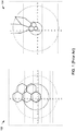
- FIG. 1 shows that a projection of equal aperture antenna radiation patterns (shown in chart 104) onto the surface results in some large beams at the intended edge of coverage (shown in chart 102). Some of these beams illuminate an area of nearly 3600 km 2 while others fall short of covering the intended area.
- the extended illumination at the edges of covers potentially causes interference with adjacent HAPs systems and may not be usable because the user terminal elevation angle would be very small and the path loss increases with distance from the HAP. This is not a problem for GEO satellites because the whole Earth subtends an angle of 20°, which is well inside the center HAP beam where the projection is better behaved.
- free space path loss experienced by the user terminals in the outer cells would be up to 11.6 dB greater than user terminals within the 7 inner cells because path loss is proportional to the square of the distance from the user terminal to the platform.
- rain attenuation and atmospheric gas absorption both increase with the distance the signal propagates through the atmosphere or inversely with the user terminal elevation angle. These phenomena are location dependent as rain and water vapor depend on location of the coverage area on the surface of the Earth, which may vary from desert areas to high rain areas. User terminals that travel from an inner cell to an outer cell would experience a significant QoS degradation.
- the coverage area and cells move as the HAP moves in the sky.
- a stationary user terminal within an inner cell at one point in time may be within an outer cell at another point in time. This stationary user terminal would be switched from a cell with high available bandwidth (or high QoS) to a cell with low available bandwidth (or low QoS). The user would accordingly perceive or detect a significant drop in performance while remaining in the same geographic location.
- the cells may or may not move on the surface.
- the HAP may contain mechanisms for moving the on-board antennas to compensate for the HAP movement.
- the advantages of the uniform spectral density cells still apply in this case. This case, however, also allows for creating different spectral density cells if the users are not uniformly distributed over the coverage area.
- the example platform (i.e., HAP) system disclosed herein uses differently sized antennas (or antenna elements) to provide substantially uniform QoS or surface spectral density across all cells within a coverage area.
- the differently sized antennas provide corresponding different size beam widths, which compensates for the angle at which Earth subtends at 17 km to 22 km resulting in substantially similarly sized cells.
- Such a configuration of differently sized antennas maintains a consistent QoS or available bandwidth throughout the cells of a coverage area so that a user does not experience service degradation when the user terminal moves between cells and/or the HAP moves relative to a user terminal.
- antennas covering the outer cells are relatively larger (and consequently have more gain) than those antennas coving the interior cells.
- the increased gain for the antennas covering the outer cells compensates, in part, for the increased path loss from the greater distance to reach those outer cells.
- the consistent cell sizes means that link margins between user terminals and the HAP are similar, which means that antennas on the user terminals can be the same regardless of the location of the user terminal within the coverage area.
- FIG. 2 shows a diagram of an example satellite communication system 200, according to an example embodiment of the present disclosure.
- the example satellite communication system 200 includes a platform 202 (e.g., a HAP) configured to operate at a specified altitude above the Earth's surface 204.
- the platform 202 may operate between 17 to 22 km above the surface of the Earth.
- the platform 202 may be replaced by any other suitable communications satellite.
- the example platform 202 includes antennas 206 in addition to hardware 207 (e.g., receiver, switch, transmitter, modem, router, filter, amplifier, frequency translator computing device, processor, memory/buffer, etc.) to facilitate the relay of communications between user devices 208 and a gateway 210.
- the platform 202 may have a transponder bent-pipe design for relaying communications signals between the gateway 210 and the user terminals 208 in multiple cells.
- the platform 202 may include processing, switching or routing capability so that circuits may be switched or individual packets may be routed between different cells.
- the communications signals transmitted to/from the platform 202 can be any combination of standard or proprietary waveforms.
- the gateway can be connected to any combination of communications networks such as the Internet.
- the example hardware 207 may include a switch and/or processor that is configured to retransmit communications received from one cell back to the same cell or another cell.
- a switch may be configured to receive communication data from at least one of the gateway 210 and the user terminals 208 and determine a destination cell within a coverage area for the communication data. The switch then selects one of the plurality of antennas 206 corresponding to the destination cell to transmit the communication data and accordingly transmits the communication data via the selected antenna.
- the data could be sent to other HAPS, GEO/LEO satellites, or other aircraft.
- the example user terminal 208 can be any terminal capable of communicating with the platform 202.
- the user terminal 208 includes an antenna, transceiver, and processor to facilitate the transmission of data with the platform 202.
- the user terminals 208 may be connected to any user communications equipment or device such as a router, switch, phone or computer 209.
- the user terminal 208 may also include a mobile platform.
- the example gateway 210 includes any centralized transceiver connected to a network 213 (e.g., the PSTN, Internet, a LAN, a virtual LAN, a private LAN, etc.).
- the gateway 210 may include one or more base stations, antennas, transmitter, receiver, processor, etc. configured to convert data received from the network 213 into signals for wireless transmission to the platform 202 and convert data received from the platform 202 into signals for transmission to the network 213.
- the platform 202 may be in communication with more than one gateway 210. Additionally or alternatively, the gateway 210 may be in communication with more than one platform 202. In these instances, the gateway 210 may select which platform 202 is to receive the data based on, for example, a destination of the data.
- the example user terminals 208 and the gateway 210 are configured to communicate with the platform 202 via uplinks 214 downlinks 216.
- the links 214 and 216 use spot beams provided by the platform 202 to cover specified cells containing the user terminal 208 and/or the gateway 210.
- a spot beam may multiplex a plurality of signals on each uplink 214 and each downlink 216 based on the amount of user terminals 208 and/or gateways 210 transmitting or receiving data within a cell.
- Data is transmitted to the platform 202 from the user terminals 208 via the uplink 214a and data is received from the platform 202 at the user terminals 208 via the downlink 216a.
- data is transmitted to the platform 202 from the gateway 210 via the uplink 214b and data is received from the platform 202 at the gateway 210 via the downlink 216b.
- the gateway 210 sends communication signals to the user terminal 208 via a forward link comprising the uplink 214b and the downlink 216a and the user terminal 208 sends communications signals to the gateway 210 via the return link comprising the uplink 214a and the downlink 216b.
- the uplink 214b may use a frequency band between 47.2 and 47.5 GHz
- the downlink 216b may use a frequency band between 47.9 and 48.2 GHz
- the uplink 214a may use a frequency band between 31.0 and 31.3 GHz
- the downlink 216a may use a frequency band between 27.9 and 28.2 GHz.
- the uplink 214b may use a frequency band between 31.0 and 31.3 GHz and the downlink 216a may use a frequency band between 27.9 and 28.2 GHz and both the uplink 214b and the downlink 214b may use a frequency band between 47.2 and 47.5 GHz and 47.9 and 48.2 GHz. In the United States the allocation includes the entire band between 47.2 and 48.2 GHz.
- the advantage of the first embodiment is that rain attenuation on the user links are easier to close with higher data rates.
- the advantage of the second embodiment is that more spectrum is available for the user data links. The disclosure is not restricted to either of these frequency plans and in the future other frequencies may become available to HAP communications. If the methods and apparatus of disclosure are applied to LEO satellites, other spectrum is already available.
- the antennas 206 of the example platform 202 are configured to have different sizes (e.g., different size apertures) to create cells of substantially the same size in order to achieve a constant surface spectral density throughout the coverage area.
- a system configuration manager 212 includes any processor or system tasked with designing, developing, and/or maintaining the antennas 206, hardware 207, and other features of the platform 202. The system configuration manager 212 may determine a coverage area to be serviced by the platform 202 in addition to a number of antennas needed to provide acceptable bandwidth to user terminals and the size of the antennas to maintain spectral density uniformity among the cells.
- the system configuration manager 212 may also select the type of antenna including, for example, a reflector, array, open ended waveguide, dipole, monopole, horn, etc.
- the system configuration manager 212 may select the antenna type based on, for example, a desired spot beam size, bandwidth, gain, elevation angle relative to the surface, etc.
- the system configuration manager 212 may also select the size of the aperture of the antenna 206 based on the desired spot beam size, bandwidth, gain, elevation angle, etc.
- the system configuration manager 212 may include a control link to configure the platform 202 based on a new set of coverage area and QoS parameters. Depending on the capability of the platform 202, such parameters may include new frequency assignments, new spot beam forming coefficients or new routing tables.
- the example system configuration manager 212 may also service and/or maintain the platform 202.
- the system configuration manager 212 may transmit software updates while the platform 202 is operational in the sky.
- the system configuration manager 212 may also instruct the platform 202 to move to a new geographical location.
- the system configuration manager 212 may further instruct the platform 202 to return to the ground for maintenance, upgrades, service, antenna reconfiguration, etc.
- the system configuration manager 212 may communicate with the platform 202 via the gateway 210 and/or a proprietary/private communication link.
- the platform 202 may provide diagnostic and status information to the system configuration manager 212 via the proprietary/private communication link and/or through the gateway 210 multiplexed with communications traffic.
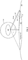
- FIG. 3 shows a diagram of an example HAP coverage area 300 for the platform 202 discussed above in conjunction with FIG. 2 , according to an example embodiment of the present disclosure.
- the platform 202 operates at an altitude of r h above the surface 204.
- the altitude r h may be any distance between, for example, 17 km and 22 km.
- the platform 202 provides communications for the coverage area 300 that falls within a maximum range 302.
- the range 302 depends, on the altitude r h , a minimum acceptable elevation angle respective to a user device (" ⁇ ") 303, and desired link margin.
- the link margin is dependent on the available platform power, platform antenna gain, terminal antenna gain, link availability requirements, terminal gain, and other equipment and link limitations.
- the platform 202 operating at 20 km may have a maximum range 302 of 75 km for a minimum elevation angle ⁇ of 15 degrees, 110 km for a minimum elevation angle ⁇ of 10 degrees and 195 km for a minimum elevation angle ⁇ of 5 degrees.
- the coverage area 300 of the platform 202 would be 36,350 km 2 .
- the coverage area 300 of the platform 202 would be 16,675 km 2 .
- the range 302 is the RF line-of-sight propagation path between the platform 202 and the user terminal 208 and the coverage area radius 301 is a measure along the arc of the surface 204 from the sub-HAP point to the edge of coverage.
- FIG. 3 also shows a spherical surface 304 which extends the u-v surface used in the design of GEO satellites.
- the u-v surface is nearly planar since the Earth subtends an angle of only 20 degrees with respect to this surface.
- this surface cannot be approximated by a plane and must be considered spherical.
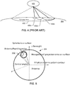
- FIG. 4 shows a diagram of a coverage area 400 of a HAP 402 that includes antennas of the same size (or have the same aperture) similar to the prior art system described in connection with FIG. 1 .
- the position of the antenna apertures in the HAP spherical u-v surface and the projection of the radiated beams are shown respectively in the charts 102 and 104 of FIG. 1 .
- An example of the u-v surface 304 is shown in FIG. 3 .
- the HAP 402 of FIG. 4 operates at an altitude of 20 km and has a range of 75 km.
- the coverage area 400 is partitioned into 19 cells 404 including a central cell sounded by six cells, which themselves being surrounded by 12 cells.
- the HAP 402 includes 19 antennas of the same size to provide coverage respectively to the 19 cells.
- the 19 antenna patterns projected onto the u-v surface are hexagonal, as shown in the chart 102 of FIG. 1 . These hexagons are each illuminated by an antenna which is pointed normal to the u-v surface.
- An equal-gain contour for example the 3 dB contour, falls on the six vertices of the hexagon.
- the neighboring antenna illuminates an adjacent hexagon so that its 3 dB gain contour falls on the shared vertices.
- both antenna radiation patterns have the same gain and this defines the boundary between the two cells.
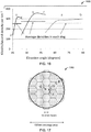
- a spherical hexagonal pattern incident on the u-v surface 304 is shown in the diagram of FIG. 5 .
- a cell 402 projects back onto a spherical hexagon 502.
- the antennas are configured to have a beamwidth or central angle measured in the plane containing the antenna system boresight and the antenna Poynting vector of 29.7° and are assumed to have an efficiency ⁇ of 55% such that the gain of the center antenna and the antennas in the outer rank would be about 15.5 dBi.
- the size of the spherical hexagons shown in FIGS. 1 and 6 is determined by the desired coverage area and may not tessellate the spherical u-v surface. In this case the hexagons of FIGS. 1 and 5 would not be regular and would need to be illuminated by antenna apertures with elliptical beam contours.
- the innermost cell 404a has a diameter of 12.2 km.
- the 6 next innermost cells including the cell 404b are fan shaped and have an arc length in the radial dimension of 14.4 km, an arc length in the orthogonal dimension at an inner edge of 6.4 km, and an arc length in the orthogonal dimension at an outer edge of 21 km.
- the 12 outermost cells including the cell 404c are fan shaped and have an arc length in the radial dimension from the coverage area center of 53 km and an arc length in the orthogonal dimension that varies from about 10.5 km at an inner edge to about 38 km at an outer edge.
- the use of the same antenna size for the different cells for the relatively low altitude HAP 402 results in significantly different sized cells as shown in FIGS. 1 and 4 .
- the difference in path loss between the edge of the coverage area 400 at the cell 404c and the center of the cell 404a is about 11.6 dB.
- the outer cells would also experience more rain fading and atmospheric gas absorption as a result of the lower elevation angle and path length or range. This relatively high path loss difference between cells means that users at the edge of the coverage area 400 would experience a lower link margin and reduced bandwidth density, resulting in poorer QoS.
- FIG. 6 shows a table 600 of properties of the coverage area 400 for the prior art example discussed above in conjunction with FIG. 4 .
- the table 600 shows that the 12 outermost cells 402c each cover an area of 1283 km 2 while the innermost cell 404a only covers an area of 118 km 2 . Further, the cells 404c are further from the HAP 402 than cells 404a and 404b, which reduces the link margin. This increased path loss can be overcome by increasing the code rate but this further reduces the user data rates available. This means that the outermost cells 404c have lower available bandwidth per unit area by orders of magnitude compared to the innermost cell 404a.
- FIG. 7 shows a diagram of an example coverage area 700 that includes 19 similar sized cells.
- the coverage area 700 includes an innermost cell 702a surrounded by six next innermost cells 702b, which are surrounded by 12 outermost cells 702c.
- the antennas 206 of the platform 202 are sized differently to compensate for the different subtended angles.
- the antennas corresponding to each ring of cells 702a, 702b, and 702c may be configured to have the same dimensions since the cells within the same ring generally are the same distance from the platform 202.
- FIG. 7 also shows the cells as having a hexagonal-shape such that the entire coverage area 700 has a honeycomb shape.
- the spot beams which illuminate these cells generally have elliptical equal-gain cross sections so that the spot beams overlap.
- FIG. 8 shows the example coverage area 700 with the uniform cells 702a, 702b, and 702c.
- FIG. 9 shows the uniform cells 702 as they project back onto the spherical u-v surface 304 around the platform 202 (chart 902) and as they appear on the surface 204 (chart 904).
- the example platform 202 operates at 20 km above the surface 204 and has a range of 75 km for a user terminal elevation angle ⁇ of 15°.
- the antennas 206 are differently sized and/or have different sized apertures, the beamwidth of the antennas corresponding to different rings of cells 702a, 702b, and 702c are also different.
- the beamwidth of the antenna associated with the cell 702a is 79.7°
- the beamwidth of the antennas corresponding to the cells 702b is 25.6° by 52°
- the beamwidth of the antennas corresponding to cells 702c is 8.9° by 28°.
- the central angle or beamwidth orthogonal to the radial angular dimension in the spherical u-v surface 304 for the inner and outer rings are determined by use of the cosine law from spherical trigonometry. This configuration yields cells 702 that all have an effective diameter of 33.4 km and an area of about 878 km 2 .
- Such a configuration accordingly provides cells 702 with a substantially similar surface spectral density and bandwidth, thereby providing a communications system that has a consistent QoS across the coverage area.
- the higher gain of the antennas covering the outer ring also helps to compensate for the additional path loss.
- the system discussed in conjunction with FIG. 1 has common beamwidths among the antennas but different sized cells.
- FIG. 11 shows a diagram of differently sized antennas 206 of the platform 202 used to produce the similarly sized cells 702 of FIGS. 7 and 8 .
- the example antenna 206a corresponding to the cell 702a is configured to have an aperture diameter of 8.89 mm (0.35 inches) and a gain of 7 dB to produce a beamwidth of 79.7°.
- the beamwidth of the antenna is selected based on the angle ⁇ of the cell 702b being less than 39.9°.
- the antenna 206b may be implemented by an open ended flared waveguide.
- the example antenna 206b corresponding to the cell 702b is configured to have an elliptical aperture with dimensions of 27.18 by 11.94 mm (1.07 by 0.47 inches) and a gain of 13.4 dB to produce an elliptical beam of 25.6° by 52°.
- the radial beamwidth of the antenna 206b is selected based on the angle ⁇ of the cell 702b being between 39.9° and 65.5°.
- the antenna 206b may be implemented by a small feed horn.
- the example antenna 206c corresponding to the cells 702c is configured to have an antenna aperture configured to produce the spot beam with a beamwidth of 8.9° by 28°. Such an antenna 206c would have a gain of 21 dB. Assuming 55% aperture efficiency, the antenna 206c is configured to have an elliptical aperture of 78.99 by 25.4 mm (3.11 by 1.0 inches) at 30 GHz (as shown in FIG 11 ). A small reflector may be used to provide an antenna with these dimensions.
- antennas 206 shown in FIG. 11 may be implemented using phased arrays or other antenna technology.
- the design goal is to have a uniform user perceived QoS.
- the reasonable assumption that the user terminals 208 are uniformly distributed within a coverage area requires a uniform distribution of capacity in terms of available user data rates. It is further desirable that all of the user terminal antennas and transceivers are similar in design independent of their location within the coverage area. Since both HAPs and LEO satellites move, even stationary user terminals 208 will transition from one cell to the next cell and users will expect the same QoS without disruption. This motivates the allocation of the same amount of spectrum within each cell in conjunction with uniform cell sizes.
- FIG. 12 shows a diagram of parametric inputs to the design process implemented by the system configuration manager 212 of FIG. 2 .
- These inputs may change in time with improved technology and with new frequency spectrum allocations.
- Some of these design parameters are location dependent such as rain fall statistics and therefore rain fades.
- Some of these parameters are the choice of a service provider such as availability and minimum elevation angle or terminal costs. In any event, design process of the system configuration manager 212 remains the same.
- HAPs located 20 km above the surface 204 may move within a circle having a 0.25 km radius. At the sub-HAP point on the surface this corresponds to an angle of 0.7 degrees. If a non-tracking antenna is desired for the user terminal 208 then this constrains the antenna to a 3 dB beamwidth of 1.4 degrees and therefore constrains the gain of the user terminal antenna as well.
- new antenna designs with modest tracking capability are becoming available in the same time frame as HAP technology.
- This design example assumes an antenna with a 1 degree 3 dB beam width and the ability to track +/- 0.5 degrees. This may be achieved with a reflector antenna illuminated by a small feed array of 16 elements, for example. This results in a standard user terminal gain of 45 dBi. It is further assumed that the user terminal receiver has a noise figure of 5 dB corresponding to a noise temperature of 627 degrees K.
- Atmospheric attenuation due to rain, clouds and gas absorption is dependent on location.
- the standard atmosphere described in International Telecommunication Union ("ITU") Recommendations P.676, P.618, P.840, and P.838 is assumed.
- local atmospheric data if available, is used.
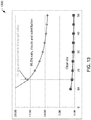
- This additional loss is shown graph 1300 of FIG. 13 as a function of elevation angle for the example embodiment.
- the graph 1300 of FIG. 13 shows there is a total attenuation of 99.5% (fade of 15 db) for signals with a 28 GHz frequency due to rain, clouds, gas absorption, and scintillation.
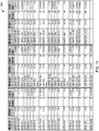
- link budgets are computed assuming the same modulation and coding waveforms as used in the DVB-S2 standard. This data is given by the table 1400 shown in FIG. 14 where the modulation and coding schemes are ranked by Eb/No.
- the DVB-S2 waveform is use for the example embodiment but the described process is not limited to this particular waveform.
- the results of the system configuration process include HAPs design parameters such as antenna apertures and required transmit power levels per cell. If the links do not close at the edge of coverage or if excessive transmit power is required then the input parameters must be re-evaluated. Design modifications include increasing the performance requirements on the user terminal 208 (i.e., more antenna gain), using a lower frequency with better rain attenuation performance, reducing the size of the coverage area (i.e., increasing the minimum user terminal elevation angle), and/or using an alternative coverage area embodiment by partitioning the coverage area into more cells.
- the output design has a uniform user data rate density of about 250 kb/sec/km 2 , which is about an order of magnitude higher than that achieved by many of the current operating satellite systems.
- the total HAPs transmit power measured at the HAPs antenna flange is only 6.6 Watts, which is well within the expected available power for commercial HAPS.
- the locations within the coverage area of the points on the curve of FIG. 16 are shown in coverage area 1700 of FIG. 17 . In this case, these results are so good that the system configuration may be reevaluated with more relaxed user terminal performance requirements or the designer may consider extending the range of coverage or increasing the link availability above 99.5%.
- Another design possibility includes reducing the total number of cells within the coverage area from 19 to 7 (i.e., one center cell 702a and one outer ring of six cells 702b). However this reduces the total user data throughput of the system.
- the system configuration manager 212 of FIG. 2 may choose not to use a beamwidth of 80° for the center cell 702a because the gain for the antenna 206a is only 7 dB compared to gains of 13.4 dB and 21 dB respectively for the antennas illuminating cells 702b and 702c.
- Such an antenna is likely to have high side lobe radiation potentially interfering with the reuse of its frequency allocation in other beams.
- the difference in path loss at the outer cells 702c is only 11.6 dB.
- the inner cell 702a may have the worst case link margins compared to the outer cells 702c in clear weather, excluding the attenuation due to atmospheric gas absorption.
- side lobes of the antenna 206a may be high enough to interfere with the reception of the other antennas 206b and 206c, thereby limiting frequency reuse.
- the center cell 702a may further be divided into seven sub-cells 1802, as shown in FIG. 18 .
- the spectrum or bandwidth available to each of the sub-cells is divided by seven from the total spectrum allocated to the center cell 702a. This configuration reduces the noise bandwidth and improves the link margins since the antenna gain would be 14.1 dB for the centermost cell 1802 and 16.3 dB for the surrounding cells 1802, which is similar to the gains of 13.4 dB and 21 dB for the antennas illuminating cells 702b and 702c.
- FIG. 19 shows a table 1900 comparing the area and bandwidth of the cells 702b and 702c and the cells 1802. While the coverage area of each of the cells 1802 is smaller at 125 km 2 , the surface spectral density is the same as the cells 702b and 702c because the spectrum for each of the cells 1802 is reduced to 21 MHz or 150/7 MHz. This configuration enables smaller beamwidths to be used for the center of the coverage area 702 rather than 80°, which provides consistent QoS between the outer cells 702c and the innermost cells 1802.
- FIG. 20 shows a diagram of a coverage area 2000 of the example platform 202 of FIG. 2 that includes 37 equal-sized cells 2002.
- the cells 2002 are partitioned into four different rings with a first ring including cell 2002a, a second ring including six cells 2002b, a third ring including 12 cells 2002c, and a fourth ring including 18 cells 2002d.
- the antennas 206 corresponding to the cells 2002 of the same rings have similar dimensions while the dimensions between the antennas of the different rings differ. This configuration of antennas produces a surface spectral density that is roughly uniform throughout the coverage area 2002.
- an antenna corresponding to the cell 2002a is configured to have an aperture diameter (and beamwidth) corresponding to an elevation angle of 59 degrees at the edge of cell coverage and an effective cell radius of 12 km.
- the six antennas corresponding to six cells 2002b are configured to have an aperture diameter (and beamwidth) corresponding to an elevation angle of 32.1 degrees at the edge of cell coverage and an effective cell radius of 12 km.
- the 12 antennas corresponding to 12 cells 2002c are configured to have an aperture diameter (and beamwidth) corresponding to an elevation angle of 20.7 degrees at the edge of cell coverage and an effective cell radius of 12 km.
- the 19 antennas corresponding to 19 cells 2002d are configured to have an aperture diameter (and beamwidth) corresponding to an elevation angle of 15 degrees at the edge of cell coverage and an effective cell radius of 12 km.
- Such a configuration of antennas having different sizes produces cells 2002 with diameters of approximately 24 km.
- the cells 2002 are smaller than the cells 702, the beamwidth for the center cell 2002a is reduced from 79.7° to 69.8° and the gain increased from 7 to 9.2 dB.
- a coverage area 2200 includes an outer ring of 12 cells, an inner ring of 6 cells, and a center cell.
- the inner ring of 6 cells from the first embodiment described in conjunction with FIGS. 7 to 11 may be divided or sectored each into multiple cells, as shown in FIG. 22 .
- each cell in the outer ring is sectored into 3 separate cells.
- the beam necessary to illuminate each sector would be nearly circular with a beamwidth of 8.8° by 9.3°.
- the dimensions of the antenna aperture would be elliptical at 78.99 by 74.93 mm (3.11 by 2.95 inches) and would have a gain of 25.8 dB. This represents an improvement of about 5 dB over the design with non-sectored cells and all three beams can be produced by a single fixed phased array.
- FIG. 23 illustrates a flow diagram showing an example procedure 2300 to configure antennas on a platform 202 to produce cells with a substantially uniform surface spectral density, according to an example embodiment of the present disclosure.
- procedure 2300 is described with reference to the flow diagram illustrated in FIG. 23 , it should be appreciated that many other methods of performing the steps associated with the procedure 2300 may be used. For example, the order of many of the blocks may be changed, certain blocks may be combined with other blocks, and many of the blocks described are optional. Further, the actions described in procedure 2300 may be performed among multiple devices.
- the example procedure 2300 of FIG. 23 operates on, for example, the system configuration manager 212 of FIG. 2 .
- the procedure 2300 begins when the system configuration manager 212 receives a request 2301 to provision a HAP (e.g., the platform 202 of FIG. 2 ) for a specified coverage area.
- the request 2301 may include, for example a latitude (e.g., geographic location) at which the proposed HAP will operate.
- the request 2301 may also include a season of the year in which the HAP will operate.
- the system configuration manager 212 determines an altitude at which the HAP will operate (block 2302). The altitude depends on the altitude of the tropopause, where the atmospheric winds are minimal. This altitude in turn depends on the latitude of the coverage area. A preliminary edge-of-coverage link analysis may be performed at this time.
- the system configuration manager 212 may use parametric inputs 2305 (e.g., terminal design constraints, HAP constraints, available spectrum, rain/atmospheric absorption fade statistics, etc.) described in conjunction with FIGS. 12 to 17 to determine the minimum elevation angle and the maximum communication range.
- the system configuration manager 212 determines a coverage area for the specified area (block 2304). It should be noted that the costs of installation can increase with lower elevation angles since it becomes more difficult to site an antenna with visibility to the HAP when surrounded by buildings and trees.
- the example system configuration manager 212 further determines bandwidth requirements and/or QoS requirements/parameters for the coverage area (block 2306).
- the bandwidth requirements may be based on inputs 2307 including, for example, a number of users or subscribers.
- the configuration manager 212 then partitions the coverage area into cells (block 2308). In some instances, the cells may be equal-sized hexagonal cells. After partitioning the coverage area, the example system configuration manager 212 is configured to assign an antenna to each of the cells (block 2310).
- the system configuration manager 212 next determines a beamwidth, elevation angle, and/or gain for each antenna to provide communication coverage to the respective cell according to the bandwidth requirements and/or QoS requirements (block 2312).
- the system configuration manager 212 determines an aperture size and/or an antenna type for each of the antennas based, for example, on the determined beamwidth, gain, elevation angle, etc. such that each cell has the same size and/or surface spectral density (block 2314).
- the aperture size and/or an antenna type for each of the antennas may also be based on link performance requirements 2315 and/or the availability of antenna designs.
- the system configuration manager 212 then performs a link analysis to determine if there is adequate link margin for the required level of service (block 2316).
- the HAP is provisioned (block 2318) and the procedure 2300 ends until another HAP is requested to be provisioned into service.
- the example procedure 1500 may also begin again if the HAP is returned from operation for an upgrade and/or modification.
- the system designer may configure the beam forming coefficients of the phased array to form new spot beams while the HAP is flying.
- the example procedure 2300 returns to block 2304.
- the system configuration manager 212 determines a modified coverage area, minimum elevation angle, and maximum range that provides sufficient margin. For example, a smaller coverage area may be necessary or the number of cells may need to be increased from 19 to 37.
- the present invention provides a telecommunications platform apparatus selected from a high altitude platform or a satellite platform, said apparatus including a plurality of antennas configured to provide communication coverage among a plurality of terminals within a specified area on the ground, each antenna being configured to communicate with a specified cell within the specified area, wherein the antennas have differently sized apertures to maintain a similar surface spectral density among the cells within the specified area.
- the plurality of terminals includes user terminals and a gateway, and wherein communications are between the gateway and user terminals.
- each of the antennas that communicates with the gateway is at least one of mechanically and electrically controlled to continually point at the gateway.
- the plurality of terminals associated with the telecommunications platform communicates with a plurality of terminals associated with a second telecommunications platform via a communications link between the telecommunications platforms.
- the apertures of the antennas corresponding to cells at outer edges of the specified area have a larger area than apertures of antennas corresponding to cells within a center of the specified area.
- the telecommunications platform apparatus includes a low earth orbit satellite.
- the telecommunications platform apparatus includes a high altitude platform.
- the high altitude platform operates between 17 km and 22 km above a center of the specified area of the ground.
- the plurality of antennas is configured to provide substantially uniform spectral density coverage to each of the plurality of terminals.
- the telecommunications platform apparatus is communicatively coupled to a GEO satellite.
- the telecommunications platform apparatus causes the cells on the surface to remain substantially stationary.
- the telecommunications platform apparatus causes the cells on the surface to move within the specified area.
- each of the cells have an approximately hexagonal-shape and the antennas are arranged such that the corresponding cells form a honeycomb shape within the specified area.
- the apertures of the antennas are configured such that each of the hexagonal-shaped cells has a similar area.
- the plurality of antennas includes 19 antennas and the specified area is partitioned into 19 cells such that: the 19 cells have an area of 878 km 2 and a radius of 16.7 km, an antenna corresponding to a cell within a center of the specified area is configured to have a beamwidth of 79.7° and an aperture diameter of 8.89 mm (0.35 inches) conditioned on the apparatus operating between 28 to 30 GHz, six antennas corresponding to six cells around the center cell of the specified area are configured to have an elliptical 3 dB beam contour of 25.6° by 52°, an aperture with dimensions of 27.18 by 11.94 mm (1.07 by 0.47 inches), and a gain of 13.4 dB conditioned on the apparatus operating between 28 to 30 GHz, and 12 antennas corresponding to 12 cells around the six cells of the specified area are configured to have an elliptical 3 dB beam contour of 8.9° by 28°
- the antennas each have a downlink spectrum of 150 MHz.
- the center antenna includes an open ended waveguide antenna, the six antennas include small horn antennas, and the 12 antennas include small reflector antennas.
- the antennas are at least one of fixed or variable phased array antennas.
- the plurality of antennas includes 25 antennas and the specified area is partitioned into 25 cells such that: an inner seven cells have an area of 125 km 2 and a radius of 6.3 km, an antenna corresponding to a central cell of the inner seven cells within a central area of the specified area is configured to have a beamwidth of 35.1°, an aperture diameter of 19.81 mm (0.78 inches), and a gain of 14.1 dB conditioned on the apparatus operating between 28 to 30 GHz, six antennas corresponding to six cells of the inner seven cells positioned around the center cell of the specified area are configured to have an elliptical 3 dB beam contour of 22.3° by 33°, an aperture with dimensions of 31.24 by 21.08 mm (1.23 by 0.83 inches), and a gain of 16.3 dB conditioned on the apparatus operating between 28 to 30 GHz, six antennas corresponding to outer six cells around the seven inner cells of the
- the seven antennas corresponding to the seven inner cells are configured to cover the cells each with an area of about 125 km 2
- the six antennas are configured to cover the six outer cells each with an area of about 878 km 2
- the 12 antennas are configured to cover cells each with an area of about 878 km 2 .
- the plurality of antennas includes 37 antennas and the specified area is partitioned into 37 cells such that: each cell has an area of 450 km 2 and a radius of 12 km, one antenna corresponding to a central cell within the specified area is configured to have a beamwidth of 61.8°, an aperture diameter of 11.43 mm (0.45 inches), and a gain of 9.2 dB conditioned on the apparatus operating between 28 to 30 GHz, six antennas corresponding to six cells around the central cell of the coverage area are configured to have an elliptical 3 dB beam contour of 26.7° by 47°, an aperture with dimensions of 26.16 by 14.99 mm (1.03 by 0.59 inches), and a gain of 14 dB conditioned on the apparatus operating between 28 to 30 GHz, 12 antennas corresponding to 12 cells around the six cells of the coverage area are configured to have an elliptical 3 dB beam contour of 8.9° by 28
- the telecommunications platform apparatus further includes a switch configured to receive communication data from at least one terminal, determine a destination cell within the specified area for the communication data, select one of the plurality of antennas corresponding to the destination cell to transmit the communication data, and transmit the communication data via the selected antenna.
- a telecommunications platform providing substantially uniform surface spectral density using the methods described herein may be an element of a larger system.
- larger system include relays between platforms, relays between platforms and GEO satellites, relays between platforms to gateways shared by those platforms, relays between gateways and GEO satellites.
Description
- The present disclosure relates in general to multibeam coverage for a high altitude platform and more specifically to a high altitude platform that includes antennas with differently sized apertures to provide substantially consistent coverage among cells of a specified area.
- Satellites provide communication coverage over a specified surface area on Earth. As discussed herein, a cell is a geographical coverage area on the surface of the Earth and a spot beam is a radiation pattern of an antenna that illuminates a cell. A surface spectral density (Hertz per square kilometer ("Hz/km2") within the coverage area is typically increased by increasing the number of radiated spot beams to partition the coverage area into multiple cells and reusing the available spectrum many times. For instance, dividing an area previously covered by one broad beam into 19 cells covered by 19 narrow spot beams and splitting the frequency spectrum into four equal parts (and reusing the spectrum in smaller cells) results in a surface spectral density that is increased by a factor of 19/4 or nearly five-times. To provide broad and uniform coverage with a high surface spectral density, the satellite or telecommunications platform accordingly may use a plurality of antennas such that each antenna is configured to provide similar communication coverage (e.g., a spot beam) to a cell. It is also common practice to create multiple beams from a single antenna by using more than one duplex feed for each antenna. Phased array and beamforming techniques are also well-known.
- Generally, antennas with identical dimensions and properties are chosen to reduce design variation. However, the variation of distances between a platform and various cells, resulting in part from the curvature of the Earth, leads to differently sized cells from identical antennas. For instance, cells directly below a platform are relatively smaller compared to cells at the edges of a specified coverage area. If the same amount of spectrum is used in each cell then the surface spectral density is greater for the smaller cells below the platform compared to the surface spectral density of the larger cells at the outer edges of coverage. Differences in surface spectral density between cells can result in service disruptions and/or service degradations or a difference in the perceived quality of service as a user moves between cells or as the cells move past the users.
- In geostationary Earth Orbit ("GEO") satellite systems, the effects of cell size differences are generally not severe or noticeable. For instance, at the geostationary orbit height of 35,786 km above the surface, Earth subtends an angle of only 20°. This means that except at the extreme edges of satellite coverage where the surface curves away from the satellite, cells within a coverage area are generally uniform. However, for satellites at lower altitudes, the differences between cell sizes are more pronounced. For instance, Earth subtends an angle of about 160° relative to a high altitude platform operating between 17 km and 22 km above the surface. This greater angle causes significant differences in cell areas covered by the same antennas. Such differences in cell size can affect the quality of service ("QoS") because coverage in the cells located on the perimeter of the coverage area is subject to higher path loss and lower surface spectral density, thereby resulting in lower user bandwidth.
- GEO satellites are stationary relative to a point on Earth but satellites in other orbits move relative to fixed points on Earth. For the latter systems, therefore even stationary user terminals will be served by different spot beams over time, i.e., the cells move with the telecommunications platform. If different cells use the same amount of frequency spectrum but have different sizes, the available bandwidth for each user terminal changes, which may cause service disruptions.
-
US 2013/009809 discloses a satellite system having at least one satellite that receives and transmits signals from/to user terminals located in a service area covered by a plurality of beams, each having frequencies allocated to allow for beam reuse. The beam sizes, the bandwidth used in each beam and the power density in each beam are chosen as a function of the user density in the service area. - According to the present invention there is provided a telecommunications platform apparatus according to
claim 1. - The present disclosure provides a new and innovative apparatus for providing multibeam coverage to connect user terminals to the Internet via gateway stations using a telecommunications platform such as a high altitude platform ("HAP") or a Low Earth Orbit ("LEO") satellite platform. The example apparatus disclosed herein use differently dimensioned antennas (e.g., antennas with differently sized apertures) to create substantially equal-sized cells (and/or cells with the same surface spectral density) within a specified user terminal coverage area. Communications links with the one or more gateway stations are provided by one or more stationary spot beams from a mechanically or electronically pointed antenna. The differently dimensioned/configured antennas provide corresponding different spot beams that compensate for the distance and subtended angle of each cell. This configuration of using differently dimensioned antennas produces a surface spectral density that is generally constant throughout a coverage area of the platform, which provides substantially uniform communication coverage among the different cells and a consistent perceived quality of service. Different sized antenna apertures may also be achieved with a single antenna with multiple feeds or a suitably designed phased array antenna.
- In an example embodiment, a telecommunications platform or transceiver apparatus includes a plurality of antennas configured to provide communication links between a gateway station and a plurality of user terminals within a specified coverage area on the ground, each user link antenna being configured to communicate with a specified cell within the specified coverage area and each gateway link antenna being configured to communicate with a specific gateway. A system configuration management apparatus includes logical links to platforms, gateways and user terminals to receive status and other management information and to download configuration and provisioning parameters. The system configuration manager also includes system design planning and updating functions. As discussed herein, planning includes the design of cell numbers and sizes and an assigned frequency plan. Based on the cell sizes, the system configuration manager may design differently sized aperture antennas for the telecommunications platform (satellite or HAPS) apparatus to maintain a similar surface spectral density among the cells within the specified area to meet specified design criteria.
- Additional features and advantages of the disclosed system, method, and apparatus are described in, and will be apparent from, the following Detailed Description and the Figures.
-
-
FIG. 1 shows a diagram of prior art equal-sized HAP antenna apertures and consequent coverage area on the surface of the Earth. -
FIG. 2 shows a diagram of an example telecommunications communication system, according to an example embodiment of the present disclosure. -
FIG. 3 shows a diagram of an example HAP coverage area for a HAP discussed above in conjunction withFIG. 1 , according to an example embodiment of the present disclosure. -
FIG. 4 shows a diagram of a coverage area of a prior art HAP that includes antennas of the same size. -
FIG. 5 shows a diagram of a spherical hexagonal pattern incident on a u-v surface. -
FIG. 6 shows a table of properties of the coverage area ofFIG. 4 . -
FIG. 7 shows a diagram of an example coverage area that includes 19 similar sized cells, according to an example embodiment of the present disclosure. -
FIG. 8 shows the example coverage area ofFIG. 7 with uniform cells, according to an example embodiment of the present disclosure. -
FIG. 9 shows the uniform cells ofFIG. 7 as they project back onto a spherical u-v surface around the platform ofFIG. 2 and as they appear on the surface of the Earth, according to an example embodiment of the present disclosure. -
FIG. 10 shows a table of properties of the cells and corresponding antennas discussed above in conjunction withFIGS. 7 and 8 , according to an example embodiment of the present disclosure. -
FIG. 11 shows a diagram of differently sized antennas of the HAP ofFIG. 2 used to produce the similarly sized cells ofFIGS. 7 and 8 , according to an example embodiment of the present disclosure. -
FIG. 12 shows a diagram of parametric inputs to a design process implemented by the system configuration manager ofFIG. 2 , according to an example embodiment of the present disclosure. -
FIG. 13 shows a diagram of a graph of representative atmospheric gas attenuation and rain attenuation for 28 GHz using an ITU reference atmospheric model, according to an example embodiment of the present disclosure. -
FIG. 14 shows a diagram of modulation and coding schemes used in the DVB-S2 standard, according to an example embodiment of the present disclosure. -
FIG. 15 shows a diagram of exemplary results of the example described in conjunction withFIGS. 12 to 14 , according to an example embodiment of the present disclosure. -
FIG. 16 shows a diagram of surface spectral density as a function of elevation angle throughout a coverage area specified by the example described in conjunction withFIGS. 12 to 15 , according to an example embodiment of the present disclosure. -
FIG. 17 shows a diagram of the coverage area including the location of the labeled points in the diagram ofFIG. 16 , according to an example embodiment of the present disclosure. -
FIG. 18 shows a diagram of an example coverage area that includes different sized cells with the same spatial spectral density, according to an example embodiment of the present disclosure. -
FIG. 19 shows a table of properties of the cells and corresponding antennas discussed above in conjunction withFIG. 18 , according to an example embodiment of the present disclosure. -
FIG. 20 shows a diagram of an example coverage area that includes 37 similar sized cells, according to an example embodiment of the present disclosure. -
FIG. 21 shows a table of properties of the cells and corresponding antennas discussed above in conjunction withFIG. 20 , according to an example embodiment of the present disclosure. -
FIG. 22 shows a diagram of an example coverage area that includes sectored outer cells, according to an example embodiment of the present disclosure. -
FIG. 23 illustrates a flow diagram showing an example procedure to configure antennas on a HAP to produce cells with a substantially uniform spatial spectral density, according to an example embodiment of the present disclosure. - The present disclosure relates in general to a method, apparatus, and system to provide multibeam coverage by a telecommunications platform. As disclosed herein, the term 'platform' may refer to any Low Earth Orbit ("LEO") satellite, Medium Earth Orbit ("MEO") satellite, Geosynchronous Earth Orbit ("GEO") satellite, and/or High Altitude Platform ("HAP"). A HAP may include any airship, airplane, balloon, etc. operating between, for example, 17 km and 22 km over the surface.
- The example method, apparatus, and system disclosed herein use antennas with differently sized apertures to provide substantially consistent coverage among cells of a specified area. For instance, antennas may be configured to have different apertures so as to cover cells of relatively the same area and/or cells with substantially the same surface spectral density. The techniques described herein achieve uniform coverage using individual antennas per spot beam. However, the techniques are also extensible to phased arrays and/or multiple single feed per beam arrays. As discussed herein, antenna aperture is an effective area (orientated perpendicular to a direction of an incoming (or outgoing) radio wave) representative of how effective an antenna is at receiving (or transmitting) radio waves. Typically the effective area of an antenna is 55% of the actual physical area of the antenna aperture.
- HAPs using antennas configured to support communications with the same sized aperture have been envisioned since the 1970s. However, technology to support highspeed and reliable wireless communication has not become available until recently. Additionally, technology to maintain HAPs within the air for extended periods of time has only recently become available. For instance, the energy density, weight, and size of batteries, fuel cells, and solar cells have become advanced enough to support continuous operation of an airship or blimp in the sky for 30 to 60 days or more.
- HAPs have several potential advantages compared to higher altitude satellites. For instance, HAPs generally have a relatively low communication latency in the 100's of microseconds ("µsec") compared to latencies of 100's milliseconds ("msec") for GEO satellites and 10's msec for LEO satellites operating over 500 km. Additionally, HAPs have a shorter product development cycle time compared to satellites, which require space qualification in addition to engineering design that ensures continuous operation for an extended period of time (e.g., ten years). Also, launching a few GEO satellites or a large constellation of LEO satellites can be very expensive and high risk. This means that HAPs may be developed with less upfront capital investment than satellites. HAPs may also be repaired and/or upgraded relatively easily by landing the HAPs for service. In comparison, satellites cannot generally be repaired or upgraded once launched into space.
- Further, HAPs may be provisioned one at a time so that a HAP-based communication system can be rolled out to different geographic areas at different times without affecting performance of other HAPs within the system. In contrast to HAPs, satellites are expensive and generally take several years to design, build, qualify, and launch before service can begin. LEO satellite systems also generally require that all satellites be provisioned at the same time to provide system wide coverage.
- Another disadvantage of satellites is that there is generally too much capacity provided in low usage areas. Satellites have coverage areas that are relatively large where a sizable portion of the coverage area includes oceans, lakes, deserts, forests, and protected lands that have few (if any) users. Additionally, some LEO satellites spend a significant amount of time orbiting over oceans and other uninhabited areas. Since a sizeable portion of the coverage area (and consequently bandwidth) is provided to sparsely populated areas, satellites have trouble providing enough capacity in relatively small high usage areas where the amount of bandwidth for that area is limited. In contrast, HAPs are deployed where there are large concentrations of users (e.g., cities), thereby providing service where there is the greatest demand/need.
- A further disadvantage of satellites is the power and antenna size needed to provide high QoS communications. Satellites are generally thousands of kilometers above the surface, which requires high power output per antenna and larger antenna sizes to maintain acceptable QoS parameters. HAPs in contrast are much closer to the surface (e.g., 17 km to 22 km) and can provide the same (or better) QoS with lower power and smaller antennas.
- Some HAPs have been proposed that use satellite communication technology including antennas and transceivers. These HAPs accordingly have antennas (or antenna elements) of the same size to provide spot beams to respective cells of a coverage area. These antennas provide spot beams with the same beam widths. However, the size of each cell under this antenna configuration varies significantly based on the location of the cell relative to the HAP. This cell area difference becomes larger for cells at the perimeter of the coverage area and becomes significantly pronounced for HAPs that operate at less than 30 km from the surface.
- For example, a typical HAP that operates 20 km above the surface may have 19 antennas that provide communication coverage to 19 respective cells. In aggregate, the 19 cells define a coverage area of the HAP. In this example, if it is assumed that a surface coverage radius of 75 km, which corresponds to a minimum elevation angle at a user terminal at the edge of coverage of 15 degrees, the use of similar sized antennas results in the cell in the center of the coverage area having a surface area of 118 km2 and the 12 outer cells each having a surface area of 1283 km2. This results in a cell size difference of 1165 km2 between inner and outer cells of the coverage area. In other words, the inner cell is less than 9% the size of the larger outer cells. Assuming the density of users per square km within the coverage area is constant, users in the outer cells would have a factor of 11 less available bandwidth and significantly reduced QoS compared to users in the innermost seven cells.
FIG. 1 shows that a projection of equal aperture antenna radiation patterns (shown in chart 104) onto the surface results in some large beams at the intended edge of coverage (shown in chart 102). Some of these beams illuminate an area of nearly 3600 km2 while others fall short of covering the intended area. The extended illumination at the edges of covers potentially causes interference with adjacent HAPs systems and may not be usable because the user terminal elevation angle would be very small and the path loss increases with distance from the HAP. This is not a problem for GEO satellites because the whole Earth subtends an angle of 20°, which is well inside the center HAP beam where the projection is better behaved. - Additionally, free space path loss experienced by the user terminals in the outer cells would be up to 11.6 dB greater than user terminals within the 7 inner cells because path loss is proportional to the square of the distance from the user terminal to the platform. Additionally, rain attenuation and atmospheric gas absorption both increase with the distance the signal propagates through the atmosphere or inversely with the user terminal elevation angle. These phenomena are location dependent as rain and water vapor depend on location of the coverage area on the surface of the Earth, which may vary from desert areas to high rain areas. User terminals that travel from an inner cell to an outer cell would experience a significant QoS degradation.
- In instances where the HAP is mobile or the cells provided by the HAP are mobile, the coverage area and cells move as the HAP moves in the sky. A stationary user terminal within an inner cell at one point in time may be within an outer cell at another point in time. This stationary user terminal would be switched from a cell with high available bandwidth (or high QoS) to a cell with low available bandwidth (or low QoS). The user would accordingly perceive or detect a significant drop in performance while remaining in the same geographic location.
- Additionally, in instances where the HAP position is substantially held constant by navigating in figure eights/circles, or flying into the wind, the cells may or may not move on the surface. The HAP may contain mechanisms for moving the on-board antennas to compensate for the HAP movement. The advantages of the uniform spectral density cells still apply in this case. This case, however, also allows for creating different spectral density cells if the users are not uniformly distributed over the coverage area.
- The example platform (i.e., HAP) system disclosed herein uses differently sized antennas (or antenna elements) to provide substantially uniform QoS or surface spectral density across all cells within a coverage area. The differently sized antennas provide corresponding different size beam widths, which compensates for the angle at which Earth subtends at 17 km to 22 km resulting in substantially similarly sized cells. Such a configuration of differently sized antennas maintains a consistent QoS or available bandwidth throughout the cells of a coverage area so that a user does not experience service degradation when the user terminal moves between cells and/or the HAP moves relative to a user terminal. To maintain consistent cell areas, antennas covering the outer cells are relatively larger (and consequently have more gain) than those antennas coving the interior cells. The increased gain for the antennas covering the outer cells compensates, in part, for the increased path loss from the greater distance to reach those outer cells. Further, the consistent cell sizes means that link margins between user terminals and the HAP are similar, which means that antennas on the user terminals can be the same regardless of the location of the user terminal within the coverage area.
-
FIG. 2 shows a diagram of an examplesatellite communication system 200, according to an example embodiment of the present disclosure. The examplesatellite communication system 200 includes a platform 202 (e.g., a HAP) configured to operate at a specified altitude above the Earth'ssurface 204. For instance, theplatform 202 may operate between 17 to 22 km above the surface of the Earth. In other examples, theplatform 202 may be replaced by any other suitable communications satellite. - The
example platform 202 includesantennas 206 in addition to hardware 207 (e.g., receiver, switch, transmitter, modem, router, filter, amplifier, frequency translator computing device, processor, memory/buffer, etc.) to facilitate the relay of communications betweenuser devices 208 and agateway 210. For example, theplatform 202 may have a transponder bent-pipe design for relaying communications signals between thegateway 210 and theuser terminals 208 in multiple cells. In some embodiments, theplatform 202 may include processing, switching or routing capability so that circuits may be switched or individual packets may be routed between different cells. The communications signals transmitted to/from theplatform 202 can be any combination of standard or proprietary waveforms. Additionally, the gateway can be connected to any combination of communications networks such as the Internet. - The
example hardware 207 may include a switch and/or processor that is configured to retransmit communications received from one cell back to the same cell or another cell. For instance, a switch may be configured to receive communication data from at least one of thegateway 210 and theuser terminals 208 and determine a destination cell within a coverage area for the communication data. The switch then selects one of the plurality ofantennas 206 corresponding to the destination cell to transmit the communication data and accordingly transmits the communication data via the selected antenna. In other embodiments the data could be sent to other HAPS, GEO/LEO satellites, or other aircraft. - The
example user terminal 208 can be any terminal capable of communicating with theplatform 202. Theuser terminal 208 includes an antenna, transceiver, and processor to facilitate the transmission of data with theplatform 202. Theuser terminals 208 may be connected to any user communications equipment or device such as a router, switch, phone orcomputer 209. Theuser terminal 208 may also include a mobile platform. - The
example gateway 210 includes any centralized transceiver connected to a network 213 (e.g., the PSTN, Internet, a LAN, a virtual LAN, a private LAN, etc.). Thegateway 210 may include one or more base stations, antennas, transmitter, receiver, processor, etc. configured to convert data received from thenetwork 213 into signals for wireless transmission to theplatform 202 and convert data received from theplatform 202 into signals for transmission to thenetwork 213. In some instances, theplatform 202 may be in communication with more than onegateway 210. Additionally or alternatively, thegateway 210 may be in communication with more than oneplatform 202. In these instances, thegateway 210 may select whichplatform 202 is to receive the data based on, for example, a destination of the data. - The
example user terminals 208 and thegateway 210 are configured to communicate with theplatform 202 via uplinks 214 downlinks 216. The links 214 and 216 use spot beams provided by theplatform 202 to cover specified cells containing theuser terminal 208 and/or thegateway 210. It should be appreciated that a spot beam may multiplex a plurality of signals on each uplink 214 and each downlink 216 based on the amount ofuser terminals 208 and/orgateways 210 transmitting or receiving data within a cell. Data is transmitted to theplatform 202 from theuser terminals 208 via theuplink 214a and data is received from theplatform 202 at theuser terminals 208 via thedownlink 216a. Similarly, data is transmitted to theplatform 202 from thegateway 210 via theuplink 214b and data is received from theplatform 202 at thegateway 210 via thedownlink 216b. Thegateway 210 sends communication signals to theuser terminal 208 via a forward link comprising theuplink 214b and thedownlink 216a and theuser terminal 208 sends communications signals to thegateway 210 via the return link comprising theuplink 214a and thedownlink 216b. - Mesh connectivity between
user terminals 208 in the same or difference cells is also possible depending on the capabilities of the communications platform, i.e., theplatform 202 or a satellite. While the disclosure is not limited to any frequency, certain frequency spectrums have been allocated for HAP communications by regulatory bodies. These allocated frequencies are used in the example discussed herein. The example embodiment assumes theuplink 214b may use a frequency band between 47.2 and 47.5 GHz, thedownlink 216b may use a frequency band between 47.9 and 48.2 GHz, theuplink 214a may use a frequency band between 31.0 and 31.3 GHz and thedownlink 216a may use a frequency band between 27.9 and 28.2 GHz. - Another possible embodiment assumes the
uplink 214b may use a frequency band between 31.0 and 31.3 GHz and thedownlink 216a may use a frequency band between 27.9 and 28.2 GHz and both theuplink 214b and thedownlink 214b may use a frequency band between 47.2 and 47.5 GHz and 47.9 and 48.2 GHz. In the United States the allocation includes the entire band between 47.2 and 48.2 GHz. The advantage of the first embodiment is that rain attenuation on the user links are easier to close with higher data rates. The advantage of the second embodiment is that more spectrum is available for the user data links. The disclosure is not restricted to either of these frequency plans and in the future other frequencies may become available to HAP communications. If the methods and apparatus of disclosure are applied to LEO satellites, other spectrum is already available. - As discussed in more detail below, the
antennas 206 of theexample platform 202 are configured to have different sizes (e.g., different size apertures) to create cells of substantially the same size in order to achieve a constant surface spectral density throughout the coverage area. Asystem configuration manager 212 includes any processor or system tasked with designing, developing, and/or maintaining theantennas 206,hardware 207, and other features of theplatform 202. Thesystem configuration manager 212 may determine a coverage area to be serviced by theplatform 202 in addition to a number of antennas needed to provide acceptable bandwidth to user terminals and the size of the antennas to maintain spectral density uniformity among the cells. Thesystem configuration manager 212 may also select the type of antenna including, for example, a reflector, array, open ended waveguide, dipole, monopole, horn, etc. Thesystem configuration manager 212 may select the antenna type based on, for example, a desired spot beam size, bandwidth, gain, elevation angle relative to the surface, etc. Thesystem configuration manager 212 may also select the size of the aperture of theantenna 206 based on the desired spot beam size, bandwidth, gain, elevation angle, etc. In some instances, thesystem configuration manager 212 may include a control link to configure theplatform 202 based on a new set of coverage area and QoS parameters. Depending on the capability of theplatform 202, such parameters may include new frequency assignments, new spot beam forming coefficients or new routing tables. - In addition to configuring the
platform 202, the examplesystem configuration manager 212 may also service and/or maintain theplatform 202. For example, thesystem configuration manager 212 may transmit software updates while theplatform 202 is operational in the sky. Thesystem configuration manager 212 may also instruct theplatform 202 to move to a new geographical location. Thesystem configuration manager 212 may further instruct theplatform 202 to return to the ground for maintenance, upgrades, service, antenna reconfiguration, etc. Thesystem configuration manager 212 may communicate with theplatform 202 via thegateway 210 and/or a proprietary/private communication link. In some instances, theplatform 202 may provide diagnostic and status information to thesystem configuration manager 212 via the proprietary/private communication link and/or through thegateway 210 multiplexed with communications traffic. -
FIG. 3 shows a diagram of an exampleHAP coverage area 300 for theplatform 202 discussed above in conjunction withFIG. 2 , according to an example embodiment of the present disclosure. In this example, theplatform 202 operates at an altitude of rh above thesurface 204. The altitude rh may be any distance between, for example, 17 km and 22 km. Theplatform 202 provides communications for thecoverage area 300 that falls within amaximum range 302. Therange 302 depends, on the altitude rh, a minimum acceptable elevation angle respective to a user device ("γ") 303, and desired link margin. The link margin is dependent on the available platform power, platform antenna gain, terminal antenna gain, link availability requirements, terminal gain, and other equipment and link limitations. For example, theplatform 202 operating at 20 km may have amaximum range 302 of 75 km for a minimum elevation angle γ of 15 degrees, 110 km for a minimum elevation angle γ of 10 degrees and 195 km for a minimum elevation angle γ of 5 degrees. Assuming, for example, amaximum range 302 of 110 km and a minimum elevation angle γ of 10°, thecoverage area 300 of theplatform 202 would be 36,350 km2. Alternatively, assuming amaximum range 302 of 75 km for a minimum elevation angle γ of 15 degrees, thecoverage area 300 of theplatform 202 would be 16,675 km2. Note the distinction betweenrange 302 inFIG. 3 andcoverage area radius 301 inFIG. 3 . Therange 302 is the RF line-of-sight propagation path between theplatform 202 and theuser terminal 208 and thecoverage area radius 301 is a measure along the arc of thesurface 204 from the sub-HAP point to the edge of coverage. -
FIG. 3 also shows aspherical surface 304 which extends the u-v surface used in the design of GEO satellites. In a GEO system the u-v surface is nearly planar since the Earth subtends an angle of only 20 degrees with respect to this surface. For HAPs and LEO satellites, this surface cannot be approximated by a plane and must be considered spherical. -
FIG. 4 shows a diagram of acoverage area 400 of aHAP 402 that includes antennas of the same size (or have the same aperture) similar to the prior art system described in connection withFIG. 1 . The position of the antenna apertures in the HAP spherical u-v surface and the projection of the radiated beams are shown respectively in thecharts FIG. 1 . An example of theu-v surface 304 is shown inFIG. 3 . Similar toFIG. 3 , theHAP 402 ofFIG. 4 operates at an altitude of 20 km and has a range of 75 km. In this example thecoverage area 400 is partitioned into 19 cells 404 including a central cell sounded by six cells, which themselves being surrounded by 12 cells. TheHAP 402 includes 19 antennas of the same size to provide coverage respectively to the 19 cells. The 19 antenna patterns projected onto the u-v surface are hexagonal, as shown in thechart 102 ofFIG. 1 . These hexagons are each illuminated by an antenna which is pointed normal to the u-v surface. An equal-gain contour, for example the 3 dB contour, falls on the six vertices of the hexagon. The neighboring antenna illuminates an adjacent hexagon so that its 3 dB gain contour falls on the shared vertices. Along the line connecting the vertices both antenna radiation patterns have the same gain and this defines the boundary between the two cells. - A spherical hexagonal pattern incident on the
u-v surface 304 is shown in the diagram ofFIG. 5 . In this figure, acell 402 projects back onto aspherical hexagon 502. In this example, the antennas are configured to have a beamwidth or central angle measured in the plane containing the antenna system boresight and the antenna Poynting vector of 29.7° and are assumed to have an efficiency η of 55% such that the gain of the center antenna and the antennas in the outer rank would be about 15.5 dBi. Note that the size of the spherical hexagons shown inFIGS. 1 and6 is determined by the desired coverage area and may not tessellate the spherical u-v surface. In this case the hexagons ofFIGS. 1 and5 would not be regular and would need to be illuminated by antenna apertures with elliptical beam contours. - When these beams are projected onto the
surface 204 the center beam illuminates a circular area and the inner and outer ring of beams project fan shaped coverage areas on the surface. The innermost cell 404a has a diameter of 12.2 km. In comparison, the 6 next innermost cells including the cell 404b are fan shaped and have an arc length in the radial dimension of 14.4 km, an arc length in the orthogonal dimension at an inner edge of 6.4 km, and an arc length in the orthogonal dimension at an outer edge of 21 km. Additionally, the 12 outermost cells including the cell 404c are fan shaped and have an arc length in the radial dimension from the coverage area center of 53 km and an arc length in the orthogonal dimension that varies from about 10.5 km at an inner edge to about 38 km at an outer edge. The use of the same antenna size for the different cells for the relativelylow altitude HAP 402 results in significantly different sized cells as shown inFIGS. 1 and4 . Additionally, the difference in path loss between the edge of thecoverage area 400 at the cell 404c and the center of the cell 404a is about 11.6 dB. Further, the outer cells would also experience more rain fading and atmospheric gas absorption as a result of the lower elevation angle and path length or range. This relatively high path loss difference between cells means that users at the edge of thecoverage area 400 would experience a lower link margin and reduced bandwidth density, resulting in poorer QoS. -
FIG. 6 shows a table 600 of properties of thecoverage area 400 for the prior art example discussed above in conjunction withFIG. 4 . The table 600 shows that the 12outermost cells 402c each cover an area of 1283 km2 while the innermost cell 404a only covers an area of 118 km2. Further, the cells 404c are further from theHAP 402 than cells 404a and 404b, which reduces the link margin. This increased path loss can be overcome by increasing the code rate but this further reduces the user data rates available. This means that the outermost cells 404c have lower available bandwidth per unit area by orders of magnitude compared to the innermost cell 404a. - To overcome the issues of having differently sized cells, especially at the outermost cells, the
antennas 206 of theexample platform 202 ofFIG. 2 are configured such that the cells have a substantially uniform area and/or surface spectral density.FIG. 7 shows a diagram of anexample coverage area 700 that includes 19 similar sized cells. Thecoverage area 700 includes aninnermost cell 702a surrounded by six nextinnermost cells 702b, which are surrounded by 12outermost cells 702c. Theantennas 206 of theplatform 202 are sized differently to compensate for the different subtended angles. In some instances, the antennas corresponding to each ring ofcells platform 202.FIG. 7 also shows the cells as having a hexagonal-shape such that theentire coverage area 700 has a honeycomb shape. The spot beams which illuminate these cells generally have elliptical equal-gain cross sections so that the spot beams overlap. -
FIG. 8 shows theexample coverage area 700 with theuniform cells FIG. 9 shows the uniform cells 702 as they project back onto the sphericalu-v surface 304 around the platform 202 (chart 902) and as they appear on the surface 204 (chart 904). Similar to the prior art example discussed above in conjunction withFIGS. 1 and4 , theexample platform 202 operates at 20 km above thesurface 204 and has a range of 75 km for a user terminal elevation angle γ of 15°. However, since theantennas 206 are differently sized and/or have different sized apertures, the beamwidth of the antennas corresponding to different rings ofcells FIG. 10 , the beamwidth of the antenna associated with thecell 702a is 79.7°, the beamwidth of the antennas corresponding to thecells 702b is 25.6° by 52°, and the beamwidth of the antennas corresponding tocells 702c is 8.9° by 28°. The central angle or beamwidth orthogonal to the radial angular dimension in the sphericalu-v surface 304 for the inner and outer rings are determined by use of the cosine law from spherical trigonometry. This configuration yields cells 702 that all have an effective diameter of 33.4 km and an area of about 878 km2. Such a configuration accordingly provides cells 702 with a substantially similar surface spectral density and bandwidth, thereby providing a communications system that has a consistent QoS across the coverage area. The higher gain of the antennas covering the outer ring also helps to compensate for the additional path loss. In comparison, the system discussed in conjunction withFIG. 1 has common beamwidths among the antennas but different sized cells. -
FIG. 11 shows a diagram of differentlysized antennas 206 of theplatform 202 used to produce the similarly sized cells 702 ofFIGS. 7 and 8 . The example antenna 206a corresponding to thecell 702a is configured to have an aperture diameter of 8.89 mm (0.35 inches) and a gain of 7 dB to produce a beamwidth of 79.7°. In this example, the beamwidth of the antenna is selected based on the angle α of thecell 702b being less than 39.9°. Theantenna 206b may be implemented by an open ended flared waveguide. - The
example antenna 206b corresponding to thecell 702b is configured to have an elliptical aperture with dimensions of 27.18 by 11.94 mm (1.07 by 0.47 inches) and a gain of 13.4 dB to produce an elliptical beam of 25.6° by 52°. In this example, the radial beamwidth of theantenna 206b is selected based on the angle α of thecell 702b being between 39.9° and 65.5°. Theantenna 206b may be implemented by a small feed horn. - The
example antenna 206c corresponding to thecells 702c is configured to have an antenna aperture configured to produce the spot beam with a beamwidth of 8.9° by 28°. Such anantenna 206c would have a gain of 21 dB. Assuming 55% aperture efficiency, theantenna 206c is configured to have an elliptical aperture of 78.99 by 25.4 mm (3.11 by 1.0 inches) at 30 GHz (as shown inFIG 11 ). A small reflector may be used to provide an antenna with these dimensions. - It should be appreciated that all of these
antennas 206 shown inFIG. 11 may be implemented using phased arrays or other antenna technology. - The design goal is to have a uniform user perceived QoS. The reasonable assumption that the
user terminals 208 are uniformly distributed within a coverage area requires a uniform distribution of capacity in terms of available user data rates. It is further desirable that all of the user terminal antennas and transceivers are similar in design independent of their location within the coverage area. Since both HAPs and LEO satellites move, evenstationary user terminals 208 will transition from one cell to the next cell and users will expect the same QoS without disruption. This motivates the allocation of the same amount of spectrum within each cell in conjunction with uniform cell sizes. -
FIG. 12 shows a diagram of parametric inputs to the design process implemented by thesystem configuration manager 212 ofFIG. 2 . These inputs may change in time with improved technology and with new frequency spectrum allocations. Some of these design parameters are location dependent such as rain fall statistics and therefore rain fades. Some of these parameters are the choice of a service provider such as availability and minimum elevation angle or terminal costs. In any event, design process of thesystem configuration manager 212 remains the same. - Current estimates are that HAPs located 20 km above the
surface 204 may move within a circle having a 0.25 km radius. At the sub-HAP point on the surface this corresponds to an angle of 0.7 degrees. If a non-tracking antenna is desired for theuser terminal 208 then this constrains the antenna to a 3 dB beamwidth of 1.4 degrees and therefore constrains the gain of the user terminal antenna as well. However, new antenna designs with modest tracking capability are becoming available in the same time frame as HAP technology. This design example assumes an antenna with a 1degree 3 dB beam width and the ability to track +/- 0.5 degrees. This may be achieved with a reflector antenna illuminated by a small feed array of 16 elements, for example. This results in a standard user terminal gain of 45 dBi. It is further assumed that the user terminal receiver has a noise figure of 5 dB corresponding to a noise temperature of 627 degrees K. - Atmospheric attenuation due to rain, clouds and gas absorption is dependent on location. For the purposes of this example the standard atmosphere described in International Telecommunication Union ("ITU") Recommendations P.676, P.618, P.840, and P.838 is assumed. For each HAP configuration, local atmospheric data, if available, is used. This additional loss is shown
graph 1300 ofFIG. 13 as a function of elevation angle for the example embodiment. For example, thegraph 1300 ofFIG. 13 shows there is a total attenuation of 99.5% (fade of 15 db) for signals with a 28 GHz frequency due to rain, clouds, gas absorption, and scintillation. - In order to estimate the user data rate available at any possible user terminal location within the coverage area, link budgets are computed assuming the same modulation and coding waveforms as used in the DVB-S2 standard. This data is given by the table 1400 shown in
FIG. 14 where the modulation and coding schemes are ranked by Eb/No. The DVB-S2 waveform is use for the example embodiment but the described process is not limited to this particular waveform. - The results of the system configuration process include HAPs design parameters such as antenna apertures and required transmit power levels per cell. If the links do not close at the edge of coverage or if excessive transmit power is required then the input parameters must be re-evaluated. Design modifications include increasing the performance requirements on the user terminal 208 (i.e., more antenna gain), using a lower frequency with better rain attenuation performance, reducing the size of the coverage area (i.e., increasing the minimum user terminal elevation angle), and/or using an alternative coverage area embodiment by partitioning the coverage area into more cells.
- In the example shown by table 1500 of
FIG. 15 andgraph 1600 ofFIG. 16 , the output design has a uniform user data rate density of about 250 kb/sec/km2, which is about an order of magnitude higher than that achieved by many of the current operating satellite systems. In addition the total HAPs transmit power measured at the HAPs antenna flange is only 6.6 Watts, which is well within the expected available power for commercial HAPS. The locations within the coverage area of the points on the curve ofFIG. 16 are shown incoverage area 1700 ofFIG. 17 . In this case, these results are so good that the system configuration may be reevaluated with more relaxed user terminal performance requirements or the designer may consider extending the range of coverage or increasing the link availability above 99.5%. Another design possibility includes reducing the total number of cells within the coverage area from 19 to 7 (i.e., onecenter cell 702a and one outer ring of sixcells 702b). However this reduces the total user data throughput of the system. - In some instances, the
system configuration manager 212 ofFIG. 2 may choose not to use a beamwidth of 80° for thecenter cell 702a because the gain for the antenna 206a is only 7 dB compared to gains of 13.4 dB and 21 dB respectively for theantennas illuminating cells outer cells 702c is only 11.6 dB. This means that theinner cell 702a may have the worst case link margins compared to theouter cells 702c in clear weather, excluding the attenuation due to atmospheric gas absorption. However, side lobes of the antenna 206a may be high enough to interfere with the reception of theother antennas - To resolve this issue, the
center cell 702a may further be divided into seven sub-cells 1802, as shown inFIG. 18 . To maintain the same surface spectral density among thecells center cell 702a. This configuration reduces the noise bandwidth and improves the link margins since the antenna gain would be 14.1 dB for thecentermost cell 1802 and 16.3 dB for the surroundingcells 1802, which is similar to the gains of 13.4 dB and 21 dB for theantennas illuminating cells -
FIG. 19 shows a table 1900 comparing the area and bandwidth of thecells cells 1802. While the coverage area of each of thecells 1802 is smaller at 125 km2, the surface spectral density is the same as thecells cells 1802 is reduced to 21 MHz or 150/7 MHz. This configuration enables smaller beamwidths to be used for the center of the coverage area 702 rather than 80°, which provides consistent QoS between theouter cells 702c and theinnermost cells 1802. -
FIG. 20 shows a diagram of acoverage area 2000 of theexample platform 202 ofFIG. 2 that includes 37 equal-sized cells 2002. In this example, the cells 2002 are partitioned into four different rings with a firstring including cell 2002a, a second ring including sixcells 2002b, a third ring including 12cells 2002c, and a fourth ring including 18cells 2002d. Theantennas 206 corresponding to the cells 2002 of the same rings have similar dimensions while the dimensions between the antennas of the different rings differ. This configuration of antennas produces a surface spectral density that is roughly uniform throughout the coverage area 2002. - As shown in table 2100 of
FIG. 21 , an antenna corresponding to thecell 2002a is configured to have an aperture diameter (and beamwidth) corresponding to an elevation angle of 59 degrees at the edge of cell coverage and an effective cell radius of 12 km. The six antennas corresponding to sixcells 2002b are configured to have an aperture diameter (and beamwidth) corresponding to an elevation angle of 32.1 degrees at the edge of cell coverage and an effective cell radius of 12 km. The 12 antennas corresponding to 12cells 2002c are configured to have an aperture diameter (and beamwidth) corresponding to an elevation angle of 20.7 degrees at the edge of cell coverage and an effective cell radius of 12 km. Additionally, the 19 antennas corresponding to 19cells 2002d are configured to have an aperture diameter (and beamwidth) corresponding to an elevation angle of 15 degrees at the edge of cell coverage and an effective cell radius of 12 km. Such a configuration of antennas having different sizes produces cells 2002 with diameters of approximately 24 km. Further, since the cells 2002 are smaller than the cells 702, the beamwidth for thecenter cell 2002a is reduced from 79.7° to 69.8° and the gain increased from 7 to 9.2 dB. - In a fourth embodiment, a
coverage area 2200 includes an outer ring of 12 cells, an inner ring of 6 cells, and a center cell. In this embodiment, the inner ring of 6 cells from the first embodiment described in conjunction withFIGS. 7 to 11 may be divided or sectored each into multiple cells, as shown inFIG. 22 . In the example shown, each cell in the outer ring is sectored into 3 separate cells. The beam necessary to illuminate each sector would be nearly circular with a beamwidth of 8.8° by 9.3°. The dimensions of the antenna aperture would be elliptical at 78.99 by 74.93 mm (3.11 by 2.95 inches) and would have a gain of 25.8 dB. This represents an improvement of about 5 dB over the design with non-sectored cells and all three beams can be produced by a single fixed phased array. -
FIG. 23 illustrates a flow diagram showing anexample procedure 2300 to configure antennas on aplatform 202 to produce cells with a substantially uniform surface spectral density, according to an example embodiment of the present disclosure. Although theprocedure 2300 is described with reference to the flow diagram illustrated inFIG. 23 , it should be appreciated that many other methods of performing the steps associated with theprocedure 2300 may be used. For example, the order of many of the blocks may be changed, certain blocks may be combined with other blocks, and many of the blocks described are optional. Further, the actions described inprocedure 2300 may be performed among multiple devices. - The
example procedure 2300 ofFIG. 23 operates on, for example, thesystem configuration manager 212 ofFIG. 2 . Theprocedure 2300 begins when thesystem configuration manager 212 receives arequest 2301 to provision a HAP (e.g., theplatform 202 ofFIG. 2 ) for a specified coverage area. Therequest 2301 may include, for example a latitude (e.g., geographic location) at which the proposed HAP will operate. Therequest 2301 may also include a season of the year in which the HAP will operate. Responsive to therequest 2301, thesystem configuration manager 212 determines an altitude at which the HAP will operate (block 2302). The altitude depends on the altitude of the tropopause, where the atmospheric winds are minimal. This altitude in turn depends on the latitude of the coverage area. A preliminary edge-of-coverage link analysis may be performed at this time. - The
system configuration manager 212 also determines a minimum elevation angle (e.g., γ = 15°) from the ground to the HAP and a maximum communication range for the HAP (block 2304). Thesystem configuration manager 212 may use parametric inputs 2305 (e.g., terminal design constraints, HAP constraints, available spectrum, rain/atmospheric absorption fade statistics, etc.) described in conjunction withFIGS. 12 to 17 to determine the minimum elevation angle and the maximum communication range. Using the altitude, the minimum elevation angle, and the maximum range, thesystem configuration manager 212 determines a coverage area for the specified area (block 2304). It should be noted that the costs of installation can increase with lower elevation angles since it becomes more difficult to site an antenna with visibility to the HAP when surrounded by buildings and trees. - The example
system configuration manager 212 further determines bandwidth requirements and/or QoS requirements/parameters for the coverage area (block 2306). The bandwidth requirements may be based oninputs 2307 including, for example, a number of users or subscribers. Theconfiguration manager 212 then partitions the coverage area into cells (block 2308). In some instances, the cells may be equal-sized hexagonal cells. After partitioning the coverage area, the examplesystem configuration manager 212 is configured to assign an antenna to each of the cells (block 2310). - The
system configuration manager 212 next determines a beamwidth, elevation angle, and/or gain for each antenna to provide communication coverage to the respective cell according to the bandwidth requirements and/or QoS requirements (block 2312). Thesystem configuration manager 212 then determines an aperture size and/or an antenna type for each of the antennas based, for example, on the determined beamwidth, gain, elevation angle, etc. such that each cell has the same size and/or surface spectral density (block 2314). The aperture size and/or an antenna type for each of the antennas may also be based onlink performance requirements 2315 and/or the availability of antenna designs. Thesystem configuration manager 212 then performs a link analysis to determine if there is adequate link margin for the required level of service (block 2316). If there is sufficient margin, the HAP is provisioned (block 2318) and theprocedure 2300 ends until another HAP is requested to be provisioned into service. Theexample procedure 1500 may also begin again if the HAP is returned from operation for an upgrade and/or modification. However, it should be noted that if a phased array is used instead of individual antennas, the system designer may configure the beam forming coefficients of the phased array to form new spot beams while the HAP is flying. - Returning to block 2316, if there is insufficient margin, the
example procedure 2300 returns to block 2304. At this point thesystem configuration manager 212 determines a modified coverage area, minimum elevation angle, and maximum range that provides sufficient margin. For example, a smaller coverage area may be necessary or the number of cells may need to be increased from 19 to 37. - The present invention provides a telecommunications platform apparatus selected from a high altitude platform or a satellite platform, said apparatus including a plurality of antennas configured to provide communication coverage among a plurality of terminals within a specified area on the ground, each antenna being configured to communicate with a specified cell within the specified area, wherein the antennas have differently sized apertures to maintain a similar surface spectral density among the cells within the specified area.
- In one embodiment, which may be used in combination with the apparatus defined in paragraph [0089], the plurality of terminals includes user terminals and a gateway, and wherein communications are between the gateway and user terminals.
- In one embodiment, which may be used in combination with the apparatus defined in paragraph [0090], each of the antennas that communicates with the gateway is at least one of mechanically and electrically controlled to continually point at the gateway.
- In one embodiment, which may be used in combination with the apparatus defined in any one of paragraphs [0089] to [0091], the plurality of terminals associated with the telecommunications platform communicates with a plurality of terminals associated with a second telecommunications platform via a communications link between the telecommunications platforms.
- In one embodiment, which may be used in combination with the apparatus defined in any one of paragraphs [0089] to [0092], the apertures of the antennas corresponding to cells at outer edges of the specified area have a larger area than apertures of antennas corresponding to cells within a center of the specified area.
- In one embodiment, which may be used in combination with the apparatus defined in any one of paragraphs [0089] to [0093], the telecommunications platform apparatus includes a low earth orbit satellite.
- In one embodiment, which may be used in combination with the apparatus defined in any one of paragraphs [0089] to [0094], the telecommunications platform apparatus includes a high altitude platform.
- In one embodiment, which may be used in combination with the apparatus defined in any one of paragraphs [0089] to [0095], the high altitude platform operates between 17 km and 22 km above a center of the specified area of the ground.
- In one embodiment, which may be used in combination with the apparatus defined in any one of paragraphs [0089] to [0096], the plurality of antennas is configured to provide substantially uniform spectral density coverage to each of the plurality of terminals.
- In one embodiment, which may be used in combination with the apparatus defined in any one of paragraphs [0089] to [0097], the telecommunications platform apparatus is communicatively coupled to a GEO satellite.
- In one embodiment, which may be used in combination with the apparatus defined in any one of paragraphs [0089] to [0098], the telecommunications platform apparatus causes the cells on the surface to remain substantially stationary.
- In one embodiment, which may be used in combination with the apparatus defined in any one of paragraphs [0089] to [0099], the telecommunications platform apparatus causes the cells on the surface to move within the specified area.
- In one embodiment, which may be used in combination with the apparatus defined in any one of paragraphs [0089] to [00100], each of the cells have an approximately hexagonal-shape and the antennas are arranged such that the corresponding cells form a honeycomb shape within the specified area.
- In one embodiment, which may be used in combination with the apparatus defined in paragraph [00101], the apertures of the antennas are configured such that each of the hexagonal-shaped cells has a similar area.
- In one embodiment, which may be used in combination with the apparatus defined in any one of paragraphs [0089] to [00102], the plurality of antennas includes 19 antennas and the specified area is partitioned into 19 cells such that: the 19 cells have an area of 878 km2 and a radius of 16.7 km, an antenna corresponding to a cell within a center of the specified area is configured to have a beamwidth of 79.7° and an aperture diameter of 8.89 mm (0.35 inches) conditioned on the apparatus operating between 28 to 30 GHz, six antennas corresponding to six cells around the center cell of the specified area are configured to have an elliptical 3 dB beam contour of 25.6° by 52°, an aperture with dimensions of 27.18 by 11.94 mm (1.07 by 0.47 inches), and a gain of 13.4 dB conditioned on the apparatus operating between 28 to 30 GHz, and 12 antennas corresponding to 12 cells around the six cells of the specified area are configured to have an elliptical 3 dB beam contour of 8.9° by 28°, an aperture with dimensions of 78.99 by 25.4 mm (3.11 by 1.0 inches), and a gain of 21 dB conditioned on the apparatus operating between 28 to 30 GHz.
- In one embodiment, which may be used in combination with the apparatus defined in any one of paragraphs [0089] to [00103], the antennas each have a downlink spectrum of 150 MHz.
- In one embodiment, which may be used in combination with the apparatus defined in paragraph [00103], the center antenna includes an open ended waveguide antenna, the six antennas include small horn antennas, and the 12 antennas include small reflector antennas.
- In one embodiment, which may be used in combination with the apparatus defined in any one of paragraphs [0089] to [00105], the antennas are at least one of fixed or variable phased array antennas.
- In one embodiment, which may be used in combination with the apparatus defined in any one of paragraphs [0089] to [00102], the plurality of antennas includes 25 antennas and the specified area is partitioned into 25 cells such that: an inner seven cells have an area of 125 km2 and a radius of 6.3 km, an antenna corresponding to a central cell of the inner seven cells within a central area of the specified area is configured to have a beamwidth of 35.1°, an aperture diameter of 19.81 mm (0.78 inches), and a gain of 14.1 dB conditioned on the apparatus operating between 28 to 30 GHz, six antennas corresponding to six cells of the inner seven cells positioned around the center cell of the specified area are configured to have an elliptical 3 dB beam contour of 22.3° by 33°, an aperture with dimensions of 31.24 by 21.08 mm (1.23 by 0.83 inches), and a gain of 16.3 dB conditioned on the apparatus operating between 28 to 30 GHz, six antennas corresponding to outer six cells around the seven inner cells of the specified area are configured to have an elliptical 3 dB beam contour of 25.6° by 52°, an aperture with dimensions of 27.18 by 11.94 mm (1.07 by 0.47 inches), and a gain of 13.4 dB conditioned on the apparatus operating between 28 to 30 GHz, and 12 antennas corresponding to 12 cells around the outer six cells of the specified area are configured to have an elliptical 3 dB beam contour of 8.9° by 28°, an aperture with dimensions of 78.99 by 25.4 mm (3.11 by 1.0 inches), and a gain of 21 dB conditioned on the apparatus operating between 28 to 30 GHz.
- In one embodiment, which may be used in combination with the apparatus defined in paragraph [00107], the seven antennas corresponding to the seven inner cells are configured to cover the cells each with an area of about 125 km2, the six antennas are configured to cover the six outer cells each with an area of about 878 km2, and the 12 antennas are configured to cover cells each with an area of about 878 km2.
- In one embodiment, which may be used in combination with the apparatus defined in paragraph [00107] or [00108], the seven antennas, corresponding to the seven inner cells, each have a spectrum of 21.4 MHz, the six antennas, corresponding to the six outer cells, each have a spectrum of 150 MHz, and the 12 antennas each have a spectrum of 150 MHz.
- In one embodiment, which may be used in combination with the apparatus defined in any one of paragraphs [0089] to [00102], the plurality of antennas includes 37 antennas and the specified area is partitioned into 37 cells such that: each cell has an area of 450 km2 and a radius of 12 km, one antenna corresponding to a central cell within the specified area is configured to have a beamwidth of 61.8°, an aperture diameter of 11.43 mm (0.45 inches), and a gain of 9.2 dB conditioned on the apparatus operating between 28 to 30 GHz, six antennas corresponding to six cells around the central cell of the coverage area are configured to have an elliptical 3 dB beam contour of 26.7° by 47°, an aperture with dimensions of 26.16 by 14.99 mm (1.03 by 0.59 inches), and a gain of 14 dB conditioned on the apparatus operating between 28 to 30 GHz, 12 antennas corresponding to 12 cells around the six cells of the coverage area are configured to have an elliptical 3 dB beam contour of 8.9° by 28°, an aperture with dimensions of 62.48 by 25.91 mm (2.46 by 1.02 inches), and a gain of 20.2 dB conditioned on the apparatus operating between 28 to 30 GHz, and 19 antennas corresponding to 19 cells around the 12 cells of the coverage are configured to have an elliptical 3 dB beam contour of 5.5° by 18°, an aperture with dimensions of 127 by 38.1 mm (5.0 by 1.5 inches), and a gain of 25 dB conditioned on the apparatus operating between 28 to 30 GHz.
- In one embodiment, which may be used in combination with the apparatus defined in any one of paragraphs [0089] to [00110], the telecommunications platform apparatus further includes a switch configured to receive communication data from at least one terminal, determine a destination cell within the specified area for the communication data, select one of the plurality of antennas corresponding to the destination cell to transmit the communication data, and transmit the communication data via the selected antenna.
- It will be appreciated that all of the disclosed methods and procedures described herein can be implemented using one or more computer programs or components. These components may be provided as a series of computer instructions on any computer-readable medium, including RAM, ROM, flash memory, magnetic or optical disks, optical memory, or other storage media. The instructions may be configured to be executed by a processor, which when executing the series of computer instructions performs or facilitates the performance of all or part of the disclosed methods and procedures.
- It should be understood that various changes and modifications to the example embodiments described herein will be apparent to those skilled in the art.
- It should also be understood that a telecommunications platform providing substantially uniform surface spectral density using the methods described herein may be an element of a larger system. Examples of larger system include relays between platforms, relays between platforms and GEO satellites, relays between platforms to gateways shared by those platforms, relays between gateways and GEO satellites.
Claims (15)
- A telecommunications platform apparatus (202) selected from a high-altitude platform or a satellite platform, said apparatus comprising:
a plurality of antennas (206) configured to provide communication coverage among a plurality of terminals (208, 210) within a specified area on the ground, each antenna (206) being configured to communicate with a specified cell within the specified area, characterised in that the antennas (206) have differently sized apertures to maintain a substantially uniform surface spectral density among the cells within the specified area. - The apparatus (202) of Claim 1, wherein the plurality of terminals (208, 210) includes user terminals (208) and a gateway (210), and wherein communications are between the gateway and the user terminals.
- The apparatus (202) of Claim 2, wherein each of the antennas (206) that communicates with the gateway (210) is at least one of mechanically and electrically controlled to continually point at the gateway.
- The apparatus (202) of Claims 1 or 2, wherein the plurality of terminals (208, 210) associated with the telecommunications platform communicates with a plurality of terminals associated with a second telecommunications platform via a communications link between the telecommunications platforms.
- The apparatus (202) of Claims 1, 2 or 4, wherein the apertures of the antennas (206) corresponding to cells at outer edges of the specified area have a larger area than apertures of antennas (206) corresponding to cells within a center of the specified area.
- The apparatus (202) of Claim 1, which is a low-earth orbit satellite platform or a high altitude platform configured to operate between 17 km and 22 km above a center of the specified area of the ground.
- The apparatus (202) of Claims 1, 2, 4, or 6, wherein the plurality of antennas (206) is configured to provide substantially uniform spectral density coverage to each of the plurality of terminals (208, 210).
- The apparatus (202) of Claim 1, wherein the telecommunications platform apparatus is communicatively coupled to a GEO satellite.
- The apparatus (202) of Claims 1, 2, 4, or 6, wherein the telecommunications platform apparatus causes one of:the cells on the surface to remain substantially stationary; orthe cells on the surface to move within the specified area.
- The apparatus (202) of Claims 1, 2, 4, 6, or 9, wherein each of the cells has an approximately hexagonal-shape and the antennas (206) are arranged such that the corresponding cells form a honeycomb shape within the specified area, and
wherein the apertures of the antennas (206) are configured such that each of the hexagonal-shaped cells has a substantially uniform area. - The apparatus (202) of Claim 1, wherein the plurality of antennas (206) includes 19 antennas and the specified area is partitioned into 19 cells such that:the 19 cells have an area of 878 km2 and a radius of 16.7 km;an antenna (206) corresponding to a cell within a center of the specified area is configured to have a beamwidth of 79.7° and an aperture diameter of 8.89 mm (0.35 inches) conditioned on the apparatus operating between 28 to 30 GHz;six antennas (206) corresponding to six cells around the center cell of the specified area are configured to have an elliptical 3 dB beam contour of 25.6° by 52°, an aperture with dimensions of 27.18 by 11.94 mm (1.07 by 0.47 inches), and a gain of 13.4 dB conditioned on the apparatus operating between 28 to 30 GHz; and12 antennas (206) corresponding to 12 cells around the six cells of the specified area are configured to have an elliptical 3 dB beam contour of 8.9° by 28°, an aperture with dimensions of 78.99 by 25.4 mm (3.11 by 1.0 inches), and a gain of 21 dB conditioned on the apparatus operating between 28 to 30 GHz,wherein the antennas (206) each have a downlink spectrum of 150 MHz, andwherein the antennas (206) are at least one of fixed or variable phased array antennas or the center antenna (206) includes an open ended waveguide antenna, the six antennas (206) include small horn antennas, and the 12 antennas (206) include small reflector antennas.
- The apparatus (202) of Claim 1, wherein the plurality of antennas (206) includes 25 antennas and the specified area is partitioned into 25 cells such that:an inner seven cells have an area of 125 km2 and a radius of 6.3 km;an antenna (206) corresponding to a central cell of the inner seven cells within a central area of the specified area is configured to have a beamwidth of 35.1°, an aperture diameter of 0.78 inches, and a gain of 14.1 dB conditioned on the apparatus operating between 28 to 30 GHz;six antennas (206) corresponding to six cells of the inner seven cells positioned around the center cell of the specified area are configured to have an elliptical 3 dB beam contour of 22.3° by 33°, an aperture with dimensions of 31.24 by 21.08 mm (1.23 by 0.83 inches), and a gain of 16.3 dB conditioned on the apparatus operating between 28 to 30 GHz;six antennas (206) corresponding to outer six cells around the seven inner cells of the specified area are configured to have an elliptical 3 dB beam contour of 25.6° by 52°, an aperture with dimensions of 27.18 by 11.94 mm (1.07 by 0.47 inches), and a gain of 13.4 dB conditioned on the apparatus operating between 28 to 30 GHz; and12 antennas (206) corresponding to 12 cells around the outer six cells of the specified area are configured to have an elliptical 3 dB beam contour of 8.9° by 28°, an aperture with dimensions of 78.99 by 25.4 mm (3.11 by 1.0 inches), and a gain of 21 dB conditioned on the apparatus operating between 28 to 30 GHz,wherein the seven antennas corresponding to the seven inner cells are configured to cover the cells each with an area of about 125 km2, the six antennas are configured to cover the six outer cells each with an area of about 878 km2, and the 12 antennas are configured to cover cells each with an area of about 878 km2.
- The apparatus (202) of Claim 12, wherein the seven antennas (206), corresponding to the seven inner cells, each have a spectrum of 21.4 MHz, the six antennas (206), corresponding to the six outer cells, each have a spectrum of 150 MHz, and the 12 antennas (206) each have a spectrum of 150 MHz.
- The apparatus (202) of Claim 1, wherein the plurality of antennas (206) includes 37 antennas and the specified area is partitioned into 37 cells such that:each cell has an area of 450 km2 and a radius of 12 km;one antenna (206) corresponding to a central cell within the specified area is configured to have a beamwidth of 61.8°, an aperture diameter of 11.43 mm (0.45 inches), and a gain of 9.2 dB conditioned on the apparatus operating between 28 to 30 GHz;six antennas (206) corresponding to six cells around the central cell of the coverage area are configured to have an elliptical 3 dB beam contour of 26.7° by 47°, an aperture with dimensions of 26.16 by 14.99 mm (1.03 by 0.59 inches), and a gain of 14 dB conditioned on the apparatus operating between 28 to 30 GHz;12 antennas (206) corresponding to 12 cells around the six cells of the coverage area are configured to have an elliptical 3 dB beam contour of 8.9° by 28°, an aperture with dimensions of 62.48 by 25.91 mm (2.46 by 1.02 inches), and a gain of 20.2 dB conditioned on the apparatus operating between 28 to 30 GHz; and19 antennas (206) corresponding to 19 cells around the 12 cells of the coverage are configured to have an elliptical 3 dB beam contour of 5.5° by 18°, an aperture with dimensions of 127 by 38.1 mm (5.0 by 1.5 inches), and a gain of 25 dB conditioned on the apparatus operating between 28 to 30 GHz.
- The apparatus (202) of Claim 1, further comprising a switch (207) configured to:receive communication data from at least one terminal (208, 210);determine a destination cell within the specified area for the communication data;select one of the plurality of antennas (206) corresponding to the destination cell to transmit the communication data; andtransmit the communication data via the selected antenna (206).
Applications Claiming Priority (2)
| Application Number | Priority Date | Filing Date | Title |
|---|---|---|---|
| US14/510,790 US9401759B2 (en) | 2014-10-09 | 2014-10-09 | Multibeam coverage for a high altitude platform |
| PCT/US2015/054918 WO2016057907A1 (en) | 2014-10-09 | 2015-10-09 | Multibeam coverage for a high altitude platform |
Publications (3)
| Publication Number | Publication Date |
|---|---|
| EP3204985A1 EP3204985A1 (en) | 2017-08-16 |
| EP3204985A4 EP3204985A4 (en) | 2018-06-13 |
| EP3204985B1 true EP3204985B1 (en) | 2020-06-03 |
Family
ID=55653847
Family Applications (1)
| Application Number | Title | Priority Date | Filing Date |
|---|---|---|---|
| EP15849299.1A Active EP3204985B1 (en) | 2014-10-09 | 2015-10-09 | Multibeam coverage for a high altitude platform |
Country Status (3)
| Country | Link |
|---|---|
| US (2) | US9401759B2 (en) |
| EP (1) | EP3204985B1 (en) |
| WO (1) | WO2016057907A1 (en) |
Cited By (1)
| Publication number | Priority date | Publication date | Assignee | Title |
|---|---|---|---|---|
| US11888569B2 (en) | 2020-11-13 | 2024-01-30 | Intelsat US LLC | Communication system for multiple-input-multiple-output (MIMO) communication with aerial platform |
Families Citing this family (25)
| Publication number | Priority date | Publication date | Assignee | Title |
|---|---|---|---|---|
| US9736846B1 (en) * | 2015-09-29 | 2017-08-15 | Sprint Communications Company L.P. | Intelligent radiation selection for antennas in a wireless communications environment |
| US20180054806A1 (en) * | 2016-08-22 | 2018-02-22 | Alcatel-Lucent Usa, Inc. | Systems and methods for decoupling control and data channels in wireless networks |
| US10524136B2 (en) * | 2016-09-28 | 2019-12-31 | Intel IP Corporation | Apparatus, system and method of communicating via a plurality of antennas |
| CN108259111B (en) * | 2016-12-29 | 2019-07-19 | 华为技术有限公司 | A kind of disturbance coordination method and high altitude platform radio station, base station |
| WO2018128563A1 (en) * | 2017-01-04 | 2018-07-12 | Telefonaktiebolaget Lm Ericsson (Publ) | Radio network node, network node, wireless device, and methods performed therein for neighbour relationship establishment in a wireless communication network |
| CN107124726B (en) * | 2017-04-28 | 2020-04-10 | 北京邮电大学 | Multi-beam GEO system access control method based on maximized throughput |
| US10419946B1 (en) | 2018-03-07 | 2019-09-17 | Loon Llc | Systems and methods for planning high altitude platform-based communication networks |
| WO2019236913A1 (en) * | 2018-06-07 | 2019-12-12 | Blue Danube Systems, Inc. | High altitude platform cellular systems |
| US10320471B1 (en) * | 2018-06-26 | 2019-06-11 | Panasonic Avionics Corporation | Dynamic effective isotropic radiated power spectral density control |
| JP6677774B2 (en) * | 2018-08-20 | 2020-04-08 | Hapsモバイル株式会社 | Control device, program, control method, and flying object |
| US10727949B2 (en) | 2018-10-12 | 2020-07-28 | Hughes Network Systems, LLC. | Systems and methods for high-altitude radio/optical hybrid platform |
| JP7249833B2 (en) * | 2019-03-19 | 2023-03-31 | Hapsモバイル株式会社 | Communication control device, program, system, and control method |
| US11290178B2 (en) * | 2019-04-12 | 2022-03-29 | Parallel Wireless, Inc. | Using low earth orbit satellites to overcome latency |
| CN110113763B (en) * | 2019-05-24 | 2022-05-06 | 厦门大学嘉庚学院 | Self-adaptive coverage optimization method of mobile high-altitude communication platform based on perception |
| CN110602753B (en) * | 2019-07-25 | 2021-10-15 | 成都天奥集团有限公司 | Method for solving problem of frequent switching of feeder link of low-rail satellite communication system |
| US10897716B1 (en) | 2019-09-09 | 2021-01-19 | Loon Llc | Integrated access and backhaul from high altitude platforms |
| US11309958B2 (en) * | 2019-12-30 | 2022-04-19 | Hughes Network Systems, Llc | Variable stayout distance for beamhopping satellite |
| US11223977B2 (en) * | 2020-01-27 | 2022-01-11 | T-Mobile Usa, Inc. | Service-based data rate control to enhance network performance |
| CN112165345B (en) * | 2020-05-07 | 2023-01-06 | 北京邮电大学 | Multi-beam covering method and device based on array antenna segmentation |
| BR112022026766A2 (en) * | 2020-07-02 | 2023-01-17 | Eutelsat Sa | METHODS FOR DATA TRANSMISSION BETWEEN A LIMITED RESOURCES DEVICE AND A NON-GEOSTATIONARY SATELLITE AND ASSOCIATED SYSTEM |
| US11066145B1 (en) | 2020-08-28 | 2021-07-20 | H2 Clipper, Inc. | Method and apparatus for lighter-than-air airship with improved structure and delivery system |
| CA3189683A1 (en) * | 2020-08-28 | 2022-03-03 | H2 Clipper, Inc. | Method and apparatus for lighter-than-air airship with improved structure and delivery system |
| WO2022235271A1 (en) * | 2021-05-07 | 2022-11-10 | Nokia Solutions And Networks Oy | Haps and terrestrial network interference coordination |
| WO2023014061A1 (en) * | 2021-08-03 | 2023-02-09 | Samsung Electronics Co., Ltd. | Methods for scheduling uplink transmissions for non-terrestrial networks |
| CN114844581B (en) * | 2022-05-31 | 2023-06-06 | 中国联合网络通信集团有限公司 | Method and device for determining coverage effect of HAPS multi-panel phased array antenna |
Family Cites Families (21)
| Publication number | Priority date | Publication date | Assignee | Title |
|---|---|---|---|---|
| US5017925A (en) | 1989-10-02 | 1991-05-21 | Motorola, Inc. | Multiple beam deployable space antenna system |
| US5625868A (en) | 1994-03-30 | 1997-04-29 | Motorola, Inc. | Method and apparatus for load sharing in a satellite communication system |
| WO1997033790A1 (en) | 1996-03-15 | 1997-09-18 | Wong Alfred Y | High-altitude lighter-than-air stationary platforms including ion engines |
| US6708029B2 (en) | 1997-06-02 | 2004-03-16 | Hughes Electronics Corporation | Broadband communication system for mobile users in a satellite-based network |
| US6434384B1 (en) * | 1997-10-17 | 2002-08-13 | The Boeing Company | Non-uniform multi-beam satellite communications system and method |
| US6201797B1 (en) | 1997-12-12 | 2001-03-13 | At&T Wireless Services Inc. | High bandwidth delivery and internet access for airborne passengers |
| WO2000014902A2 (en) | 1998-09-08 | 2000-03-16 | Angel Technologies Corporation | Network for providing wireless communications using an atmospheric platform |
| US6216244B1 (en) | 1998-10-07 | 2001-04-10 | Cisco Systems, Inc. | Point-to-multipoint variable antenna compensation system |
| US7068974B1 (en) | 2000-06-21 | 2006-06-27 | Northrop Grumman Corporation | Beam hopping self addressed packet switched communication system with power gating |
| US6731909B2 (en) | 2001-04-04 | 2004-05-04 | The Boeing Company | Method and apparatus using a binary search pattern for identifying an interfering mobile terminal |
| US7062267B2 (en) * | 2001-09-14 | 2006-06-13 | Atc Technologies, Llc | Methods and systems for modifying satellite antenna cell patterns in response to terrestrial reuse of satellite frequencies |
| US20040092257A1 (en) * | 2002-11-12 | 2004-05-13 | Chung Kirby J. | Scalable satellite area coverage |
| US7053853B2 (en) | 2003-06-26 | 2006-05-30 | Skypilot Network, Inc. | Planar antenna for a wireless mesh network |
| US20060045038A1 (en) | 2004-08-27 | 2006-03-02 | Stanley Kay | Method and apparatus for transmitting and receiving multiple services utilizing a single receiver in a broadband satellite system |
| US7792070B1 (en) | 2007-04-13 | 2010-09-07 | Douglas Burr | Multi-beam satellite network to maximize bandwidth utilization |
| KR101125734B1 (en) | 2008-01-10 | 2012-03-27 | 샛마크코리아(주) | Antenna system for receiving signals from satellites and method for driving the same |
| SG182554A1 (en) | 2009-12-18 | 2012-08-30 | Aerovironment Inc | High altitude, long endurance, unmanned aircraft and methods of operation thereof |
| WO2012140471A1 (en) | 2011-04-12 | 2012-10-18 | Agence Spatiale Europeenne | Array antenna having a radiation pattern with a controlled envelope, and method of manufacturing it |
| US20130009809A1 (en) * | 2011-07-08 | 2013-01-10 | Thales | Multi-Spot Satellite System with Efficient Space Resource Allocation |
| AU2012290305B2 (en) * | 2011-07-29 | 2014-03-27 | Viasat, Inc. | Payload for a multibeam communication satellite of a hub -spoke system with receive and transmit switching pattern synchronized over a frame for flexible forward and return capacity allocation |
| WO2014001837A1 (en) | 2012-06-29 | 2014-01-03 | Agence Spatiale Européenne | Multibeam satellite communication system and method, and satellite payload for carrying out such a method |
-
2014
- 2014-10-09 US US14/510,790 patent/US9401759B2/en active Active
-
2015
- 2015-10-09 WO PCT/US2015/054918 patent/WO2016057907A1/en active Application Filing
- 2015-10-09 EP EP15849299.1A patent/EP3204985B1/en active Active
-
2016
- 2016-07-20 US US15/214,894 patent/US9853716B2/en not_active Expired - Fee Related
Non-Patent Citations (1)
| Title |
|---|
| None * |
Cited By (1)
| Publication number | Priority date | Publication date | Assignee | Title |
|---|---|---|---|---|
| US11888569B2 (en) | 2020-11-13 | 2024-01-30 | Intelsat US LLC | Communication system for multiple-input-multiple-output (MIMO) communication with aerial platform |
Also Published As
| Publication number | Publication date |
|---|---|
| US20170237482A1 (en) | 2017-08-17 |
| US9401759B2 (en) | 2016-07-26 |
| US9853716B2 (en) | 2017-12-26 |
| EP3204985A4 (en) | 2018-06-13 |
| US20160105806A1 (en) | 2016-04-14 |
| EP3204985A1 (en) | 2017-08-16 |
| WO2016057907A1 (en) | 2016-04-14 |
Similar Documents
| Publication | Publication Date | Title |
|---|---|---|
| EP3204985B1 (en) | Multibeam coverage for a high altitude platform | |
| EP3245747B1 (en) | High altitude platform with multibeam coverage for aero-based terminals | |
| Djuknic et al. | Establishing wireless communications services via high-altitude aeronautical platforms: a concept whose time has come? | |
| KR100878646B1 (en) | Communications system | |
| CN107018514B (en) | Spectrum sharing between aircraft-based air-to-ground communication systems and existing geostationary satellite services | |
| CN107431519B (en) | Process and apparatus for improved data transfer | |
| CN107070532B (en) | System for providing high speed communication service in airborne wireless cellular network | |
| JP3086864B2 (en) | Multi-beam antenna for wireless communication network | |
| US20170207847A1 (en) | Antenna beam management and gateway design for broadband access using unmanned aerial vehicle (uav) platforms | |
| CN107431509B (en) | Method and apparatus for multiple beam-like generation and use | |
| US7027769B1 (en) | GEO stationary communications system with minimal delay | |
| US10511378B2 (en) | Hybrid analog/digital beam forming rain fade mitigation | |
| ES2385622T3 (en) | Frequency reuse in a geosynchronous satellite communication system | |
| EP3427409B1 (en) | Improving frequency reuse efficiency via interference avoidance for multi-beam satellite communications network | |
| EP3114777B1 (en) | Combined satellite and terrestrial communication system for terminals located on a vehicle such as an aircraft using a common set of frequencies. | |
| CN111585635B (en) | Satellite internet system design method based on space-frequency hybrid multiple access mode | |
| Johni | Measurements to design a coverage area by using high altitude platform systems | |
| Lagunas et al. | Beam splash mitigation for ngso spectrum coexistence between feeder and user downlink | |
| US20150029932A1 (en) | Ultra broadband networks and methods | |
| S Abdulwafi | Performance of CDMA power control for HAPS | |
| El-Disi | A thesis on utilizing high altitude platforms (haps) to provide wirelss communications coverage to close coverage gaps-case study: providing umts service to the non-radar coverage area in the Gulf of Mexico (GOMEX) |
Legal Events
| Date | Code | Title | Description |
|---|---|---|---|
| STAA | Information on the status of an ep patent application or granted ep patent |
Free format text: STATUS: THE INTERNATIONAL PUBLICATION HAS BEEN MADE |
|
| PUAI | Public reference made under article 153(3) epc to a published international application that has entered the european phase |
Free format text: ORIGINAL CODE: 0009012 |
|
| STAA | Information on the status of an ep patent application or granted ep patent |
Free format text: STATUS: REQUEST FOR EXAMINATION WAS MADE |
|
| 17P | Request for examination filed |
Effective date: 20170509 |
|
| AK | Designated contracting states |
Kind code of ref document: A1 Designated state(s): AL AT BE BG CH CY CZ DE DK EE ES FI FR GB GR HR HU IE IS IT LI LT LU LV MC MK MT NL NO PL PT RO RS SE SI SK SM TR |
|
| AX | Request for extension of the european patent |
Extension state: BA ME |
|
| DAV | Request for validation of the european patent (deleted) | ||
| DAX | Request for extension of the european patent (deleted) | ||
| A4 | Supplementary search report drawn up and despatched |
Effective date: 20180515 |
|
| RIC1 | Information provided on ipc code assigned before grant |
Ipc: H01Q 3/00 20060101AFI20180508BHEP Ipc: H04B 7/204 20060101ALI20180508BHEP |
|
| STAA | Information on the status of an ep patent application or granted ep patent |
Free format text: STATUS: EXAMINATION IS IN PROGRESS |
|
| 17Q | First examination report despatched |
Effective date: 20190107 |
|
| GRAP | Despatch of communication of intention to grant a patent |
Free format text: ORIGINAL CODE: EPIDOSNIGR1 |
|
| STAA | Information on the status of an ep patent application or granted ep patent |
Free format text: STATUS: GRANT OF PATENT IS INTENDED |
|
| INTG | Intention to grant announced |
Effective date: 20191219 |
|
| GRAS | Grant fee paid |
Free format text: ORIGINAL CODE: EPIDOSNIGR3 |
|
| GRAA | (expected) grant |
Free format text: ORIGINAL CODE: 0009210 |
|
| STAA | Information on the status of an ep patent application or granted ep patent |
Free format text: STATUS: THE PATENT HAS BEEN GRANTED |
|
| AK | Designated contracting states |
Kind code of ref document: B1 Designated state(s): AL AT BE BG CH CY CZ DE DK EE ES FI FR GB GR HR HU IE IS IT LI LT LU LV MC MK MT NL NO PL PT RO RS SE SI SK SM TR |
|
| REG | Reference to a national code |
Ref country code: GB Ref legal event code: FG4D |
|
| REG | Reference to a national code |
Ref country code: CH Ref legal event code: EP Ref country code: AT Ref legal event code: REF Ref document number: 1277993 Country of ref document: AT Kind code of ref document: T Effective date: 20200615 |
|
| REG | Reference to a national code |
Ref country code: DE Ref legal event code: R096 Ref document number: 602015053895 Country of ref document: DE |
|
| REG | Reference to a national code |
Ref country code: LT Ref legal event code: MG4D |
|
| PG25 | Lapsed in a contracting state [announced via postgrant information from national office to epo] |
Ref country code: SE Free format text: LAPSE BECAUSE OF FAILURE TO SUBMIT A TRANSLATION OF THE DESCRIPTION OR TO PAY THE FEE WITHIN THE PRESCRIBED TIME-LIMIT Effective date: 20200603 Ref country code: LT Free format text: LAPSE BECAUSE OF FAILURE TO SUBMIT A TRANSLATION OF THE DESCRIPTION OR TO PAY THE FEE WITHIN THE PRESCRIBED TIME-LIMIT Effective date: 20200603 Ref country code: FI Free format text: LAPSE BECAUSE OF FAILURE TO SUBMIT A TRANSLATION OF THE DESCRIPTION OR TO PAY THE FEE WITHIN THE PRESCRIBED TIME-LIMIT Effective date: 20200603 Ref country code: NO Free format text: LAPSE BECAUSE OF FAILURE TO SUBMIT A TRANSLATION OF THE DESCRIPTION OR TO PAY THE FEE WITHIN THE PRESCRIBED TIME-LIMIT Effective date: 20200903 Ref country code: GR Free format text: LAPSE BECAUSE OF FAILURE TO SUBMIT A TRANSLATION OF THE DESCRIPTION OR TO PAY THE FEE WITHIN THE PRESCRIBED TIME-LIMIT Effective date: 20200904 |
|
| REG | Reference to a national code |
Ref country code: NL Ref legal event code: MP Effective date: 20200603 |
|
| PG25 | Lapsed in a contracting state [announced via postgrant information from national office to epo] |
Ref country code: LV Free format text: LAPSE BECAUSE OF FAILURE TO SUBMIT A TRANSLATION OF THE DESCRIPTION OR TO PAY THE FEE WITHIN THE PRESCRIBED TIME-LIMIT Effective date: 20200603 Ref country code: HR Free format text: LAPSE BECAUSE OF FAILURE TO SUBMIT A TRANSLATION OF THE DESCRIPTION OR TO PAY THE FEE WITHIN THE PRESCRIBED TIME-LIMIT Effective date: 20200603 Ref country code: BG Free format text: LAPSE BECAUSE OF FAILURE TO SUBMIT A TRANSLATION OF THE DESCRIPTION OR TO PAY THE FEE WITHIN THE PRESCRIBED TIME-LIMIT Effective date: 20200903 Ref country code: RS Free format text: LAPSE BECAUSE OF FAILURE TO SUBMIT A TRANSLATION OF THE DESCRIPTION OR TO PAY THE FEE WITHIN THE PRESCRIBED TIME-LIMIT Effective date: 20200603 |
|
| REG | Reference to a national code |
Ref country code: AT Ref legal event code: MK05 Ref document number: 1277993 Country of ref document: AT Kind code of ref document: T Effective date: 20200603 |
|
| PG25 | Lapsed in a contracting state [announced via postgrant information from national office to epo] |
Ref country code: NL Free format text: LAPSE BECAUSE OF FAILURE TO SUBMIT A TRANSLATION OF THE DESCRIPTION OR TO PAY THE FEE WITHIN THE PRESCRIBED TIME-LIMIT Effective date: 20200603 Ref country code: AL Free format text: LAPSE BECAUSE OF FAILURE TO SUBMIT A TRANSLATION OF THE DESCRIPTION OR TO PAY THE FEE WITHIN THE PRESCRIBED TIME-LIMIT Effective date: 20200603 |
|
| PG25 | Lapsed in a contracting state [announced via postgrant information from national office to epo] |
Ref country code: RO Free format text: LAPSE BECAUSE OF FAILURE TO SUBMIT A TRANSLATION OF THE DESCRIPTION OR TO PAY THE FEE WITHIN THE PRESCRIBED TIME-LIMIT Effective date: 20200603 Ref country code: CZ Free format text: LAPSE BECAUSE OF FAILURE TO SUBMIT A TRANSLATION OF THE DESCRIPTION OR TO PAY THE FEE WITHIN THE PRESCRIBED TIME-LIMIT Effective date: 20200603 Ref country code: PT Free format text: LAPSE BECAUSE OF FAILURE TO SUBMIT A TRANSLATION OF THE DESCRIPTION OR TO PAY THE FEE WITHIN THE PRESCRIBED TIME-LIMIT Effective date: 20201006 Ref country code: ES Free format text: LAPSE BECAUSE OF FAILURE TO SUBMIT A TRANSLATION OF THE DESCRIPTION OR TO PAY THE FEE WITHIN THE PRESCRIBED TIME-LIMIT Effective date: 20200603 Ref country code: IT Free format text: LAPSE BECAUSE OF FAILURE TO SUBMIT A TRANSLATION OF THE DESCRIPTION OR TO PAY THE FEE WITHIN THE PRESCRIBED TIME-LIMIT Effective date: 20200603 Ref country code: SM Free format text: LAPSE BECAUSE OF FAILURE TO SUBMIT A TRANSLATION OF THE DESCRIPTION OR TO PAY THE FEE WITHIN THE PRESCRIBED TIME-LIMIT Effective date: 20200603 Ref country code: EE Free format text: LAPSE BECAUSE OF FAILURE TO SUBMIT A TRANSLATION OF THE DESCRIPTION OR TO PAY THE FEE WITHIN THE PRESCRIBED TIME-LIMIT Effective date: 20200603 Ref country code: AT Free format text: LAPSE BECAUSE OF FAILURE TO SUBMIT A TRANSLATION OF THE DESCRIPTION OR TO PAY THE FEE WITHIN THE PRESCRIBED TIME-LIMIT Effective date: 20200603 |
|
| PG25 | Lapsed in a contracting state [announced via postgrant information from national office to epo] |
Ref country code: PL Free format text: LAPSE BECAUSE OF FAILURE TO SUBMIT A TRANSLATION OF THE DESCRIPTION OR TO PAY THE FEE WITHIN THE PRESCRIBED TIME-LIMIT Effective date: 20200603 Ref country code: SK Free format text: LAPSE BECAUSE OF FAILURE TO SUBMIT A TRANSLATION OF THE DESCRIPTION OR TO PAY THE FEE WITHIN THE PRESCRIBED TIME-LIMIT Effective date: 20200603 Ref country code: IS Free format text: LAPSE BECAUSE OF FAILURE TO SUBMIT A TRANSLATION OF THE DESCRIPTION OR TO PAY THE FEE WITHIN THE PRESCRIBED TIME-LIMIT Effective date: 20201003 |
|
| REG | Reference to a national code |
Ref country code: DE Ref legal event code: R097 Ref document number: 602015053895 Country of ref document: DE |
|
| PLBE | No opposition filed within time limit |
Free format text: ORIGINAL CODE: 0009261 |
|
| STAA | Information on the status of an ep patent application or granted ep patent |
Free format text: STATUS: NO OPPOSITION FILED WITHIN TIME LIMIT |
|
| PG25 | Lapsed in a contracting state [announced via postgrant information from national office to epo] |
Ref country code: DK Free format text: LAPSE BECAUSE OF FAILURE TO SUBMIT A TRANSLATION OF THE DESCRIPTION OR TO PAY THE FEE WITHIN THE PRESCRIBED TIME-LIMIT Effective date: 20200603 |
|
| REG | Reference to a national code |
Ref country code: DE Ref legal event code: R119 Ref document number: 602015053895 Country of ref document: DE |
|
| 26N | No opposition filed |
Effective date: 20210304 |
|
| PG25 | Lapsed in a contracting state [announced via postgrant information from national office to epo] |
Ref country code: SI Free format text: LAPSE BECAUSE OF FAILURE TO SUBMIT A TRANSLATION OF THE DESCRIPTION OR TO PAY THE FEE WITHIN THE PRESCRIBED TIME-LIMIT Effective date: 20200603 |
|
| REG | Reference to a national code |
Ref country code: CH Ref legal event code: PL |
|
| GBPC | Gb: european patent ceased through non-payment of renewal fee |
Effective date: 20201009 |
|
| PG25 | Lapsed in a contracting state [announced via postgrant information from national office to epo] |
Ref country code: LU Free format text: LAPSE BECAUSE OF NON-PAYMENT OF DUE FEES Effective date: 20201009 Ref country code: MC Free format text: LAPSE BECAUSE OF FAILURE TO SUBMIT A TRANSLATION OF THE DESCRIPTION OR TO PAY THE FEE WITHIN THE PRESCRIBED TIME-LIMIT Effective date: 20200603 |
|
| REG | Reference to a national code |
Ref country code: BE Ref legal event code: MM Effective date: 20201031 |
|
| PG25 | Lapsed in a contracting state [announced via postgrant information from national office to epo] |
Ref country code: FR Free format text: LAPSE BECAUSE OF NON-PAYMENT OF DUE FEES Effective date: 20201031 Ref country code: DE Free format text: LAPSE BECAUSE OF NON-PAYMENT OF DUE FEES Effective date: 20210501 |
|
| PG25 | Lapsed in a contracting state [announced via postgrant information from national office to epo] |
Ref country code: GB Free format text: LAPSE BECAUSE OF NON-PAYMENT OF DUE FEES Effective date: 20201009 Ref country code: LI Free format text: LAPSE BECAUSE OF NON-PAYMENT OF DUE FEES Effective date: 20201031 Ref country code: CH Free format text: LAPSE BECAUSE OF NON-PAYMENT OF DUE FEES Effective date: 20201031 Ref country code: BE Free format text: LAPSE BECAUSE OF NON-PAYMENT OF DUE FEES Effective date: 20201031 |
|
| PG25 | Lapsed in a contracting state [announced via postgrant information from national office to epo] |
Ref country code: IE Free format text: LAPSE BECAUSE OF NON-PAYMENT OF DUE FEES Effective date: 20201009 |
|
| PG25 | Lapsed in a contracting state [announced via postgrant information from national office to epo] |
Ref country code: TR Free format text: LAPSE BECAUSE OF FAILURE TO SUBMIT A TRANSLATION OF THE DESCRIPTION OR TO PAY THE FEE WITHIN THE PRESCRIBED TIME-LIMIT Effective date: 20200603 Ref country code: MT Free format text: LAPSE BECAUSE OF FAILURE TO SUBMIT A TRANSLATION OF THE DESCRIPTION OR TO PAY THE FEE WITHIN THE PRESCRIBED TIME-LIMIT Effective date: 20200603 Ref country code: CY Free format text: LAPSE BECAUSE OF FAILURE TO SUBMIT A TRANSLATION OF THE DESCRIPTION OR TO PAY THE FEE WITHIN THE PRESCRIBED TIME-LIMIT Effective date: 20200603 |
|
| REG | Reference to a national code |
Ref country code: GB Ref legal event code: S28 Free format text: APPLICATION FILED |
|
| PG25 | Lapsed in a contracting state [announced via postgrant information from national office to epo] |
Ref country code: MK Free format text: LAPSE BECAUSE OF FAILURE TO SUBMIT A TRANSLATION OF THE DESCRIPTION OR TO PAY THE FEE WITHIN THE PRESCRIBED TIME-LIMIT Effective date: 20200603 |
|
| REG | Reference to a national code |
Ref country code: GB Ref legal event code: S28 Free format text: RESTORATION ALLOWED Effective date: 20220822 |
|
| P01 | Opt-out of the competence of the unified patent court (upc) registered |
Effective date: 20230530 |
|
| PGFP | Annual fee paid to national office [announced via postgrant information from national office to epo] |
Ref country code: GB Payment date: 20230831 Year of fee payment: 9 |