EP3204794B1 - System for endo-rectal retraction and organ immobilization for radiotherapy of the pelvis - Google Patents
System for endo-rectal retraction and organ immobilization for radiotherapy of the pelvis Download PDFInfo
- Publication number
- EP3204794B1 EP3204794B1 EP15848657.1A EP15848657A EP3204794B1 EP 3204794 B1 EP3204794 B1 EP 3204794B1 EP 15848657 A EP15848657 A EP 15848657A EP 3204794 B1 EP3204794 B1 EP 3204794B1
- Authority
- EP
- European Patent Office
- Prior art keywords
- probe body
- recited
- rectum
- film
- dose
- Prior art date
- Legal status (The legal status is an assumption and is not a legal conclusion. Google has not performed a legal analysis and makes no representation as to the accuracy of the status listed.)
- Active
Links
Images


Classifications
-
- A—HUMAN NECESSITIES
- A61—MEDICAL OR VETERINARY SCIENCE; HYGIENE
- A61N—ELECTROTHERAPY; MAGNETOTHERAPY; RADIATION THERAPY; ULTRASOUND THERAPY
- A61N5/00—Radiation therapy
- A61N5/10—X-ray therapy; Gamma-ray therapy; Particle-irradiation therapy
- A61N5/1048—Monitoring, verifying, controlling systems and methods
- A61N5/1071—Monitoring, verifying, controlling systems and methods for verifying the dose delivered by the treatment plan
-
- A—HUMAN NECESSITIES
- A61—MEDICAL OR VETERINARY SCIENCE; HYGIENE
- A61N—ELECTROTHERAPY; MAGNETOTHERAPY; RADIATION THERAPY; ULTRASOUND THERAPY
- A61N5/00—Radiation therapy
- A61N5/10—X-ray therapy; Gamma-ray therapy; Particle-irradiation therapy
- A61N5/1048—Monitoring, verifying, controlling systems and methods
- A61N5/1075—Monitoring, verifying, controlling systems and methods for testing, calibrating, or quality assurance of the radiation treatment apparatus
-
- G—PHYSICS
- G01—MEASURING; TESTING
- G01T—MEASUREMENT OF NUCLEAR OR X-RADIATION
- G01T1/00—Measuring X-radiation, gamma radiation, corpuscular radiation, or cosmic radiation
- G01T1/02—Dosimeters
- G01T1/10—Luminescent dosimeters
-
- A—HUMAN NECESSITIES
- A61—MEDICAL OR VETERINARY SCIENCE; HYGIENE
- A61N—ELECTROTHERAPY; MAGNETOTHERAPY; RADIATION THERAPY; ULTRASOUND THERAPY
- A61N5/00—Radiation therapy
- A61N5/10—X-ray therapy; Gamma-ray therapy; Particle-irradiation therapy
- A61N2005/1085—X-ray therapy; Gamma-ray therapy; Particle-irradiation therapy characterised by the type of particles applied to the patient
- A61N2005/1087—Ions; Protons
-
- A—HUMAN NECESSITIES
- A61—MEDICAL OR VETERINARY SCIENCE; HYGIENE
- A61N—ELECTROTHERAPY; MAGNETOTHERAPY; RADIATION THERAPY; ULTRASOUND THERAPY
- A61N5/00—Radiation therapy
- A61N5/10—X-ray therapy; Gamma-ray therapy; Particle-irradiation therapy
- A61N2005/1092—Details
- A61N2005/1094—Shielding, protecting against radiation
-
- A—HUMAN NECESSITIES
- A61—MEDICAL OR VETERINARY SCIENCE; HYGIENE
- A61N—ELECTROTHERAPY; MAGNETOTHERAPY; RADIATION THERAPY; ULTRASOUND THERAPY
- A61N5/00—Radiation therapy
- A61N5/10—X-ray therapy; Gamma-ray therapy; Particle-irradiation therapy
- A61N2005/1092—Details
- A61N2005/1097—Means for immobilizing the patient
Definitions
- the field of the disclosure is systems and methods for endorectal retraction during radiotherapy for prostate cancer. More particularly, the disclosure relates to systems and methods for non-invasively immobilizing the prostate gland during each treatment fraction while providing reproducible rectal retraction during subsequent treatments, thereby reducing the volume of normal tissue receiving high doses when treating prostate cancer while ensuring accurate coverage of the prostate gland.
- ablative radiotherapy of prostate cancer the dose that can be safely delivered to the prostate is limited by adjacent organs at risk (OARs), primarily the rectum and the bladder. Attempts to reduce the dose to the rectum involve advanced image guidance techniques that are used to ensure accurate patient positioning in concert with the latest in dose delivery technology to produce dose distributions with steep gradients and organs at risk sparing. However, to achieve the dose required to ablate prostate cancer, additional intervention is required to ensure the prostate is stationary during treatment and the adjacent organs at risk are spared.
- OARs adjacent organs at risk
- SABR Stereotactic Ablative Body Radiotherapy
- PTV planning target volume
- One method to safely reduce margins is through the application of prostate immobilization strategies.
- One such strategy addresses rectal motion and filling, which has consistently been a significant predicator of prostate motion.
- This strategy involves the use of endorectal balloons (ERB) to control the volume of the rectum and therefore indirectly immobilize the prostate.
- ERB endorectal balloons
- the ERB is placed in the rectum and inflated with air to expand the rectum.
- the anterior rectal wall moves toward the prostate and displaces it frontally, while the posterior wall remains in its position resulting in an increased distance between the prostate and the posterior wall. Since the endorectal balloon reduces variations in rectum filling and immobilizes the prostate, the PTV margin can be reduced, which results in a lower dose to the posterior rectal wall.
- the present disclosure overcomes the aforementioned drawbacks by providing a system and method for separating a body cavity, such as the anterior rectal membrane, away from a treatment region, such as the posterior prostate surface, using a retractor system.
- the retractor system creates sufficient separation between the sensitive organ at risk and the diseased prostate. Further, the position of the retractor can be characterized and quantified to ensure reproducible setup so that the treatment plan is reproduced during delivery.
- the retractor also acts as an immobilization device ensuring that the rectum does not rise and move into the high dose region. In addition, the retractor limits prostatic motion.
- the rectal retractor further includes a plurality of radiation detectors such that the dose can be measured and monitored after treatment delivery to ensure that treatment has been accurately delivered.
- the system includes a probe body for insertion into a body cavity near the treatment region of the patient.
- a plurality of radiation detectors are disposed along a proximal end of the probe body to measure at least one dose from the ionizing radiation source.
- a slot is disposed adjacent the plurality of radiation detectors. The slot is configured to receive a dosimetry film that, upon exposure to the at least one dose from the ionizing radiation source, indicates a quantification of the at least one dose from the ionizing radiation source.
- the probe body is dimensioned to separate a portion of the body cavity from the treatment region to reduce exposure of membranous tissue surrounding the body cavity to the at least one dose from the ionizing radiation source.
- the device includes a probe for insertion into the body cavity.
- a removable sheath including a plurality of perforations, is configured to receive the probe.
- a coupling in fluid communication with the removable sheath is configured to be coupled to at least one of a vacuum and a pump to actively remove at least one of fluid and gas from the body cavity.
- a retractor system for use in prostate, bladder, and gynecological radiotherapy, as well as prostate, bladder, and gynecological brachytherapy, for example, is provided.
- the retractor system can be used in the treatment of gynecological disorders of the cervix, uterus, and vagina.
- the retractor system may be configured to immobilize a body cavity relative to an anatomic region-of-interest.
- the retractor system inhibits prostate intrafraction and interfraction motion over the course of radiation treatment by insertion of a probe body into the body cavity.
- the effect of the retractor system on both prostate coverage and dose received by organs-at-risk (OAR), in particular the anterior rectal wall, can be evaluated using a plurality of radiation detectors disposed along the probe body. Additionally, or alternatively, in-vivo dose verification and quality assurance (QA) using dosimetry film received by a slot provided in the probe body is contemplated.
- OAR organs-at-risk
- QA quality assurance
- the retractor system 100 generally includes a base 102, a stage 104 vertically extending from the base 102, and a probe adjustment member 106 coupled to the stage 104 and configured to engage a probe body 108.
- the probe body 108 may be inserted into a body cavity (not shown), such as the rectum, of a patient to retract the body cavity away from a treatment region, such as the prostate gland, during a radiotherapy procedure.
- a removable sheath 110 having a plurality of perforations 112 may be inserted over the probe body 108 to permit gas, which may include rectal gas, to pass out of the body cavity, which may be the rectum.
- negative pressure can be applied through the addition of an external vacuum pump to ensure complete contact of the rectal membrane with the probe body 108 to maintain retraction of the anterior surface throughout treatment.
- the retractor system 100 may be a rectal retractor system for separating the anterior rectal membrane away from the posterior prostate surface to create sufficient separation between the rectum, which is a sensitive OAR, and the prostate. This separation can allow for a spatial dose gradient such that the high ablative doses given during the radiotherapy procedure can drop off to doses that are safe for the rectum. Due to the various adjustment mechanisms provided on the retractor system 100, as will be described in further detail below, the position of the retractor system 100 can be characterized and quantified to ensure reproducible setup so that the treatment plan is reproduced during delivery.
- the retractor system 100 may act as an immobilization device to ensure that the body cavity (e.g., the rectum) does not rise and move into the high dose region. Additionally, or alternatively, the retractor system 100 can monitor doses from an ionizing radiation source to a region-of-interest (e.g., the prostate gland). Furthermore, the retractor system may be indexed and fixed to the treatment bed, thereby providing immobilization for both the rectum and the prostate.
- the probe body 108 having an elongate, cylindrical shape is shown.
- the shape of the probe body 108 can be of other configurations, such as a hemispherical cylinder.
- the probe body 108 may be any suitable shape to provide immobilization.
- the probe body 108 may be constructed out of materials that can be steam sterilized, for example, and used repeatedly for subsequent radiotherapy treatments.
- the probe body 108 may include a proximal end 114 integrally coupled to a distal end 116.
- the proximal end 114 may have a diameter D 1 between about 10 millimeters and about 25 millimeters, however the diameter D 1 may have any dimension so long as the probe body 108 can sufficiently be received by the body cavity.
- the proximal end 114 may include a length dimension L that extends along a first axis X, as shown in FIG. 4 .
- the length dimension L of the proximal end 114 may be between about 70 millimeters and about 140 millimeters, however the length L may have any dimension so long as the probe body 108 can be sufficiently received by the body cavity.
- the proximal end 114 of the probe body 108 may extend along the first axis X, and the distal end 116 of the probe body 108 may extend along a second axis Y, thereby creating an angle ⁇ .
- the angle ⁇ may be between about 35 degrees and about 45 degrees, such that when the probe body 108 is inserted into a body cavity, such as the rectum, of the patient, the body cavity is separated from the treatment region.
- the probe body 108 includes a plurality of radiation detectors 118 disposed along the proximal end 114 of the probe body 108.
- the plurality of radiation detectors 118 may be disposed along a top surface 120 of the probe body 108, such that the plurality of radiation detectors 118 are adjacent an inner wall (e.g., the anterior rectal membrane wall) of the body cavity during a radiotherapy treatment.
- a gasket 119 constructed of rubber for example, may also be provided on the proximal end 114 of the probe body 108 to form a seal for the radiation detectors 118, as shown in FIG. 5 . The seal formed by the gasket 119 can inhibit bodily fluids from contaminating the radiation detectors 118.
- the plurality of radiation detectors 118 may be configured to measure one or more doses from an ionizing radiation source along the surface of the body cavity.
- the plurality of radiation detectors 118 may be optically stimulated luminescence (OSL) detectors for measuring the ionizing radiation. Based on an output from the plurality of radiation detectors 118, the quality of the delivered radiotherapy treatment can be assessed and any deviations from the intended plan can be identified. Thus, the output provided by the plurality of radiation detectors 118 can be used to monitor subsequent doses after treatment delivery to ensure that treatment has been accurately delivered.
- OSL optically stimulated luminescence
- the probe body 108 may further include a slot 122 at the proximal end 114 of the probe body 108.
- the slot 122 may be disposed adjacent the plurality of radiation detectors 118 and dimensioned to receive a dosimetry film 124.
- the dosimetry film 124 can indicate a quantification of the one or more doses.
- the dosimetry film 124 can measure in-vivo absolute dose monitoring.
- the dosimetry film 124 may be a radiographic or radiochromic film.
- the radiochromic film can be a GafChromic film, such as GafChromic EBT3 film.
- the film strips may be evaluated using FilmQA software provided by Ashland Company of Covington, KY to evaluate the color changes of the GafChromic EBT3 film.
- a software program may be used to compare the dosimetry film 124 to the planned dose distribution.
- the software program may be configured to resample the dose distribution in the plane of the dosimetry film 124 and prepare the dosimetry film 124 for cross comparison with the measured film from the endorectal retractor system 100.
- the software program is responsible for resampling the treatment plan data, calculated dose distribution, and reorienting the data in the plane of the measured dosimetry film 124 found in the probe body 108.
- the end-user can compare the calculated/estimated dose with the measured film to provide end-to-end quality assurance. Without the resampling software program, comparison between the measured dosimetry film 124 and the calculated dose may not be easily achieved.
- the distal end 116 of the probe body 108 may be a square, prism shaped member 126, for example, that is configured to be received by an opening of the probe adjustment member 106 (see FIG. 7 ).
- the square shaped member 126 may include a plurality of retention grooves 128 disposed along a surface of the square shaped member 126.
- a recess 130 may be provided on the surface of the square shaped member 126 within the plurality of retention grooves 128.
- the recess 130 may be dimensioned to receive a locking spindle 132 that extends outwardly therefrom and can translate along the second axis Y to adjust an overall height of the probe body 108 with respect to the body cavity of a patient.
- the locking spindle 132 for adjusting the probe body 108 height may be replaced by an adjustable cylindrical member (not shown) coupled to the stage 104 for adjusting the probe body 108 height.
- the square shaped member 126 of the probe body 108 may be received by an opening 134 of the probe adjustment member 106, as shown in FIG. 7 .
- a locking handle 136 may include internal threads (not shown) that engage external threads of the locking spindle 132, such that once the probe body 108 is adjusted to a desired height (i.e., by translating the locking spindle 132 within the recess 130), the locking handle 136 may be rotated to secure the probe body 108 in place.
- the probe adjustment member 106 may also allow for a rotational adjustment, as indicated by arrow R in FIG. 6 .
- a pair of cylindrical members 138 may be rotated with respect to one another.
- Each of the cylindrical members 138 includes a plurality of gear-like teeth 140 disposed around a peripheral edge 142 that are configured to incrementally engage one another as one of the cylindrical members 138 is rotated.
- a rotational locking knob 144 may be rotated to lock the gear-like teeth 140 of the cylindrical members 138 together, thereby inhibiting undesired rotation of probe body 108.
- the distal end 116 of the probe body 108 may be coupled to a shaft (not shown) that is received by an opening in the cylindrical member 138 in order to lock the rotational motion of the probe body 108.
- one of the cylindrical members 138 may include numbered indicia (not shown) disposed along a surface thereof, for example, for accurate, rotational repositioning of the probe body 108 for subsequent treatments.
- a support arm 146 may be integrally coupled to, and extend away from, for example, one of the cylindrical members 138. At an opposing end, the support arm 146 may include an aperture 148 dimensioned to receive a docking plunger 150.
- the docking plunger 150 may engage a docking socket of the stage 104. Additionally, the support arm 146 could be directly fixed to the vertical member of the translation stage 104.
- the docking plunger 150 is releasably connected to the support arm 146 and may be adjusted to increase or decrease a distance from the probe adjustment member 106 to the stage 104.
- a translation knob 152 may be coupled to the docking plunger 150 and translated in a recess 154 disposed on the support arm 146 in the direction indicated by arrow T in FIG. 6 .
- a locking screw 156 may be tightened, by rotation for example, to lock the docking plunger 150 in place.
- the docking apparatus just described may be integrally formed with a docking socket 168 of the vertical stage 104.
- the removable sheath 110 is configured to be received by the probe body 108.
- the removable sheath 110 includes a hollow cavity (see FIGS. 8 and 9 ) that is dimensioned substantially the same as the proximal end 114 of the probe body 108.
- the removable sheath 110 may allow active adherence of the inner wall of the body cavity to the probe body 108, thereby increasing immobilization of the body cavity.
- the removable sheath 110 may be constructed from a polymeric material, such as polyether ether ketone (PEEK), that can be either sterilized for repeat or single use.
- PEEK polyether ether ketone
- the plurality of perforations 112 may be circular in shape; however, the plurality of perforations 112 may be any suitable shape to permit liquid or gas (e.g., rectal gas), for example, to passively, or through the introduction of negative pressure, pass out of the body cavity (e.g., the rectum).
- the plurality of perforations 112 may exhibit any suitable perforation pattern depending on different configurations of the removable sheath 110.
- each of the plurality of perforations 112 connect to a passageway 160 that allows gas to exit the body cavity.
- a coupling 162 may be attached to the passageway 160.
- the coupling 162 may be in fluid communication with the passageway 160 of the removable sheath 110 and configured to connect to a vacuum or pump (not shown), for example.
- the vacuum or pump connected to the coupling 162 may provide an active suction process to remove liquid and/or gas from the body cavity, as well as ensure the body cavity (e.g., the rectal membrane) is adhered to the probe body 108 as the body cavity is separated from the anatomic region-of-interest (e.g., the prostate).
- each measurement guide 164 may be circumferentially disposed, inscribed and/or embossed on an outer surface 166 of the removable sheath 110.
- Each measurement guide 164 may be spaced a predetermined distance P apart.
- the predetermined distance P may be between about 4 millimeters and about 12 millimeters, for example. Knowing the predetermined distance P may allow a user to know how far the probe body 108 is inserted into the body cavity. Thus, for radiotherapy treatments that require multiple doses, the patient setup of the probe body 108 can easily be reproduced for each dose.
- the stage 104 which is configured to connect to both the probe adjustment member 106 and the base 102, is shown.
- the stage 104 allows for height adjustment, lateral adjustment, and anterior-posterior adjustment of the probe body 108. Additionally, in some embodiments, the stage 104 may include the ability to adjust the angulation of the probe body 108. These adjustments may provide controlled motion to ensure that no dramatic changes in the probe body 108 position can occur, thereby potentially limiting the risk of injury to the patient.
- the stage 104 includes the docking socket 168 configured to receive the docking plunger 150 of the probe adjustment member 106 (See FIGS. 1 and 2 for complete assembly).
- the docking socket 168 may include external threads 170 for engaging internal threads (not shown) of a safety ring 172.
- the safety ring 172 may be rotated about the external threads 170 to secure the connection between the docking plunger 150 and the docking socket 168.
- the docking socket 168 could also take the form of a thumb screw mechanism (not shown) that tightens onto the probe body 108 directly upon insertion into a slot of the stage 104.
- a cylindrical body 174 may be coupled to, or integrally formed with, the docking socket 168 of the stage 104.
- the cylindrical body 174 includes a pair of apertures 176 configured to receive a pair of fasteners 178, such as hex screws.
- Each fastener 178 may be coupled to a guide rod 180 that extends substantially perpendicular from the cylindrical body 174 along an axis Z.
- a single guide rod may be used, so long as rotational movement of the guide rod 180 about the axis Z is not permitted.
- more than two guide rods 180 may be used.
- the guide rod 180 may include numbered indicia (not shown) disposed along a surface of the guide rod 180, for example, for accurate repositioning of the probe body 108 for subsequent treatments.
- the guide rods 180 can be received by a pair of apertures 182 extending through a support member 184 to allow lateral movement of the cylindrical body 174 and, subsequently lateral movement of the probe body 108 along the axis Z. This lateral movement with respect to the whole rectal retractor system 100 is also shown in FIG. 2 by arrow Z.
- a locking screw 186 may be use to tighten the pair of apertures 182 of the support member 184 around the guide rods 180, thereby inhibiting lateral movement of the guide rods 180.
- the stage 104 further includes a rotating knob 188 that extends through a main body 190 of the stage 104 to provide a fine height adjustment of the probe body 108.
- the main body 190 includes a substantially rectangular cut-out 192 through which the rotating knob 188 extends.
- a pair of vertical support rods 194 also extend through the cut-out 192 of the main body 190 and serve as a vertical guide for a support block 196.
- the support block 196 is coupled to the support member 184, such that as the rotating knob 188 is adjusted, the support block 196, and subsequently the support member 184, translate vertically. Therefore, the rotating knob 188 can provide a fine height adjustment of the probe body 108, as it is indirectly connected to the support member 184.
- the main body 190 may further include numbered indicia (not shown) vertically disposed along a surface of the main body 190, for example, for accurate repositioning of the probe body 108 for subsequent treatments.
- a docking plug 198 Coupled to a lower end of the main body 190 of the stage 104 is a docking plug 198, as shown in FIG. 10 , that is configured to be received by a docking socket 200 of the base 102 (see FIG. 11 ).
- the docking socket 200 similar to the docking socket 168 of the stage 104, may include external threads 202 for engaging internal threads (not shown) of a safety ring 204.
- the safety ring 204 may be rotated about the external threads 202 to secure the connection between the docking plug 198 and the docking socket 200.
- the docking socket 200 may be coupled to and vertically extend from a base plate 206.
- the main body 190 of the stage 104 may be directly and/or integrally coupled to the base plate 206, thereby replacing the docking mechanism previously described.
- the base plate 206 is received by a cavity 208 of the base 102 so that the base plate 206 may translate along an axis A (also shown in FIG. 1 as arrow A). Translation along axis A allows the probe body 108 to be moved in an anterior-posterior direction.
- base 102 may include numbered indicia (not shown) disposed along a surface of the base 102, for example, for accurate repositioning of the probe body 108 along axis A for subsequent treatments.
- an opening 210 into the cavity 208 may be dimensioned so that only translation of the base plate 206 occurs along the axis A to inhibit any rotational movement, for example, of the base plate 206.
- the entire rectal retractor system 100 may be constructed to intimately connect with a treatment couch 216 such that the system 100 can only be oriented in one manner that will mitigate the risk of incorrect setup.
- the base 102 may include a plurality of apertures 218 configured to receive fasteners (not shown) that engage corresponding apertures 220 disposed on the treatment couch 216.
- a patient may be positioned in the lithotomy position and the probe body 108 may be inserted into the patient's rectum, for example.
- various adjustments of the rectal retractor system 100 can be made to ensure reproducibility of the set-up.
- the height of the probe body 108 may be adjusted by translating the square shaped member 126 in the opening 134 of the probe adjustment member 106 and locking it in place by tightening the locking handle 136.
- the probe body 108 may be rotated to a desired position and locked in place using the rotational locking knob 144 of the probe adjustment member 106, as shown in FIGS. 6 and 7 .
- the probe body 108 may also be adjusted using any of the previously described adjustment mechanisms.
- the probe body 108 is dimensioned to fixate the prostate and reduce target motion.
- the probe body 108 may also physically move the rectal wall out of the high does region.
- the distance between the prostate and rectum is increased by retraction of the rectum in posterior direction. This can reduce the dose to the rectum without compromising target coverage and also reduce movements of the prostate.
- the rectal retractor system 100 immobilizes the rectal wall and prevents changes in gas and faeces fillings. This reduces intrafractional motion of the rectum and ensures that the rectal wall does not move into the high does region of the beam. Therefore, interfractional motion does not influence the results as the retraction of the rectum is well reproduced between fractions.
- the rectal retractor system 100 provided unparalleled immobilization of the prostate gland and enables end-to-end quality assurance of treatment delivery.
- the rectal retractor system 100 is minimally invasive and does not significantly impact target and OAR dosimetry, thereby allowing HDR brachytherapy-like distributions using SABR.
- the adoption of the rectal retractor system 100 has the potential of dramatically improving patient quality of life in addition to reducing the burden on departmental resources.
Landscapes
- Health & Medical Sciences (AREA)
- Engineering & Computer Science (AREA)
- Biomedical Technology (AREA)
- Life Sciences & Earth Sciences (AREA)
- Animal Behavior & Ethology (AREA)
- Pathology (AREA)
- Nuclear Medicine, Radiotherapy & Molecular Imaging (AREA)
- Radiology & Medical Imaging (AREA)
- General Health & Medical Sciences (AREA)
- Public Health (AREA)
- Veterinary Medicine (AREA)
- Molecular Biology (AREA)
- Spectroscopy & Molecular Physics (AREA)
- High Energy & Nuclear Physics (AREA)
- General Physics & Mathematics (AREA)
- Physics & Mathematics (AREA)
- Radiation-Therapy Devices (AREA)
Description
- The field of the disclosure is systems and methods for endorectal retraction during radiotherapy for prostate cancer. More particularly, the disclosure relates to systems and methods for non-invasively immobilizing the prostate gland during each treatment fraction while providing reproducible rectal retraction during subsequent treatments, thereby reducing the volume of normal tissue receiving high doses when treating prostate cancer while ensuring accurate coverage of the prostate gland.
- In ablative radiotherapy of prostate cancer the dose that can be safely delivered to the prostate is limited by adjacent organs at risk (OARs), primarily the rectum and the bladder. Attempts to reduce the dose to the rectum involve advanced image guidance techniques that are used to ensure accurate patient positioning in concert with the latest in dose delivery technology to produce dose distributions with steep gradients and organs at risk sparing. However, to achieve the dose required to ablate prostate cancer, additional intervention is required to ensure the prostate is stationary during treatment and the adjacent organs at risk are spared.
- Evidence suggests that prostate cancer cells are sensitive to large doses per fraction (hypofractionation). This has driven a trend towards the adoption of Stereotactic Ablative Body Radiotherapy (SABR), for localized prostate cancer. The adoption of SABR has the additional benefit of improving patient access to hypofractionated treatments while simultaneously improving the cost-effectiveness of prostate radiotherapy. SABR techniques rely on an external source of radiation to deliver the radiation dose to the prostate; as such, SABR treatment planning must account for any potential prostate motion. This is typically achieved through the addition of a planning target volume (PTV) margin around the prostate. However, unacceptable late urinary and rectal complications can develop if the safety margins are too large to account for positional uncertainties, especially with such large fractional doses.
- One method to safely reduce margins is through the application of prostate immobilization strategies. One such strategy addresses rectal motion and filling, which has consistently been a significant predicator of prostate motion. This strategy involves the use of endorectal balloons (ERB) to control the volume of the rectum and therefore indirectly immobilize the prostate. Conventionally, the ERB is placed in the rectum and inflated with air to expand the rectum. The anterior rectal wall moves toward the prostate and displaces it frontally, while the posterior wall remains in its position resulting in an increased distance between the prostate and the posterior wall. Since the endorectal balloon reduces variations in rectum filling and immobilizes the prostate, the PTV margin can be reduced, which results in a lower dose to the posterior rectal wall.
- While endorectal balloons have been effective, the mechanism of inflating the ERB raises the anterior surface of the rectum into the high dose region of the treatment plan. This associated deformation of local anatomy makes it difficult to achieve dosimetric constraints that are on par with other ablative radiotherapy modalities, such as brachytherapy. While controversy remains in regards to the protective nature of the displaced normal rectal tissue, it is generally agreed that lower rectal doses results in lower rates of rectal toxicity.
- An alternative to endorectal balloons has been the use of injectable/implantable spacers or polymeric gels. The spacer gel is injected between the prostate gland and the anterior rectal wall, which increases the distance between, resulting in significantly decreased dose to the rectal wall. Although the rectal doses using this system are lower due to the physical separation of the prostate from the rectum, no evidence is available that any substantial prostate immobilizing effect is produced. These methods are also quite invasive requiring a transperineal incision or interstitial needle placement.
- It would therefore be desirable to provide a system and method for an endorectal retraction system aimed at consistently immobilizing the prostate gland during each treatment fraction, while achieving separation of the rectum from the prostate using relatively non-invasive methods, thereby increasing the space between anterior rectal wall and posterior prostate. It would also be desirable to provide favorable anterior rectal wall dosimetry with minimal organ deformation.
US 2012/230574 A1 describes a transrectal ultrasound probe for use in image-guided placement of brachytherapy seeds. - The present disclosure overcomes the aforementioned drawbacks by providing a system and method for separating a body cavity, such as the anterior rectal membrane, away from a treatment region, such as the posterior prostate surface, using a retractor system. The retractor system creates sufficient separation between the sensitive organ at risk and the diseased prostate. Further, the position of the retractor can be characterized and quantified to ensure reproducible setup so that the treatment plan is reproduced during delivery. The retractor also acts as an immobilization device ensuring that the rectum does not rise and move into the high dose region. In addition, the retractor limits prostatic motion. The rectal retractor further includes a plurality of radiation detectors such that the dose can be measured and monitored after treatment delivery to ensure that treatment has been accurately delivered.
- It is an aspect of the disclosure to provide a system for monitoring doses from an ionizing radiation source to a treatment region of a patient. The system includes a probe body for insertion into a body cavity near the treatment region of the patient. A plurality of radiation detectors are disposed along a proximal end of the probe body to measure at least one dose from the ionizing radiation source. A slot is disposed adjacent the plurality of radiation detectors. The slot is configured to receive a dosimetry film that, upon exposure to the at least one dose from the ionizing radiation source, indicates a quantification of the at least one dose from the ionizing radiation source. In addition, the probe body is dimensioned to separate a portion of the body cavity from the treatment region to reduce exposure of membranous tissue surrounding the body cavity to the at least one dose from the ionizing radiation source.
- It is another aspect of the disclosure to provide a device for immobilizing a body cavity relative to an anatomic region-of-interest. The device includes a probe for insertion into the body cavity. A removable sheath, including a plurality of perforations, is configured to receive the probe. A coupling in fluid communication with the removable sheath is configured to be coupled to at least one of a vacuum and a pump to actively remove at least one of fluid and gas from the body cavity.
- The foregoing and other aspects and advantages of the disclosure will appear from the following description. In the description, reference is made to the accompanying drawings, which form a part hereof, and in which there is shown by way of illustration a preferred embodiment of the disclosure. The invention is a defined in the appended claims.
-
-
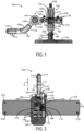
FIG. 1 is a side view of an exemplary rectal retractor system according to the present disclosure; -
FIG. 2 is a top view of the exemplary rectal retractor system ofFIG. 1 ; -
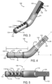
FIG. 3 is a perspective view of a probe body to be implemented into the rectal retractor system including a plurality of optical luminescence dosimeters and film dosimeters for measuring doses when practicing embodiments of the present disclosure; -
FIG. 4 is a side view of the probe body ofFIG. 3 ; -
FIG. 5 is a top view of the probe body ofFIG. 3 ; -
FIG. 6 a side view of the probe body ofFIG. 3 coupled to a probe adjustment member and a removable sheath; -
FIG. 7 is a top view of the probe body coupled to the probe adjustment member and the removable sheath ofFIG. 6 ; -
FIG. 8 is a top view of an exemplary removable sheath configured to engage the probe body according to one embodiment of the present disclosure; -
FIG. 9 is a side cross-sectional view of the exemplary removable sheath ofFIG. 8 taken along line 9-9; -
FIG. 10 is a perspective view of a vertical stage configured to receive the probe adjustment member and probe body ofFIG. 6 ; -
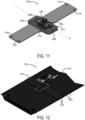
FIG. 11 is a perspective view of a base of the rectal retractor system for mounting on treatment couch; and -
FIG. 12 is a perspective view of the rectal retractor system ofFIG. 1 mounted on a treatment couch. - A retractor system for use in prostate, bladder, and gynecological radiotherapy, as well as prostate, bladder, and gynecological brachytherapy, for example, is provided. In some embodiments, the retractor system can be used in the treatment of gynecological disorders of the cervix, uterus, and vagina. The retractor system may be configured to immobilize a body cavity relative to an anatomic region-of-interest. In one example, the retractor system inhibits prostate intrafraction and interfraction motion over the course of radiation treatment by insertion of a probe body into the body cavity. The effect of the retractor system on both prostate coverage and dose received by organs-at-risk (OAR), in particular the anterior rectal wall, can be evaluated using a plurality of radiation detectors disposed along the probe body. Additionally, or alternatively, in-vivo dose verification and quality assurance (QA) using dosimetry film received by a slot provided in the probe body is contemplated.
- Referring particularly now to
FIGS. 1 and 2 , theretractor system 100 generally includes abase 102, astage 104 vertically extending from thebase 102, and aprobe adjustment member 106 coupled to thestage 104 and configured to engage aprobe body 108. Theprobe body 108 may be inserted into a body cavity (not shown), such as the rectum, of a patient to retract the body cavity away from a treatment region, such as the prostate gland, during a radiotherapy procedure. In some embodiments, aremovable sheath 110 having a plurality ofperforations 112 may be inserted over theprobe body 108 to permit gas, which may include rectal gas, to pass out of the body cavity, which may be the rectum. In addition, negative pressure can be applied through the addition of an external vacuum pump to ensure complete contact of the rectal membrane with theprobe body 108 to maintain retraction of the anterior surface throughout treatment. - In one non-limiting example, the
retractor system 100 may be a rectal retractor system for separating the anterior rectal membrane away from the posterior prostate surface to create sufficient separation between the rectum, which is a sensitive OAR, and the prostate. This separation can allow for a spatial dose gradient such that the high ablative doses given during the radiotherapy procedure can drop off to doses that are safe for the rectum. Due to the various adjustment mechanisms provided on theretractor system 100, as will be described in further detail below, the position of theretractor system 100 can be characterized and quantified to ensure reproducible setup so that the treatment plan is reproduced during delivery. Theretractor system 100, in some embodiments, may act as an immobilization device to ensure that the body cavity (e.g., the rectum) does not rise and move into the high dose region. Additionally, or alternatively, theretractor system 100 can monitor doses from an ionizing radiation source to a region-of-interest (e.g., the prostate gland). Furthermore, the retractor system may be indexed and fixed to the treatment bed, thereby providing immobilization for both the rectum and the prostate. - Turning now to
FIGS. 3-5 , theprobe body 108 having an elongate, cylindrical shape is shown. In other embodiments, the shape of theprobe body 108 can be of other configurations, such as a hemispherical cylinder. However, theprobe body 108 may be any suitable shape to provide immobilization. Theprobe body 108 may be constructed out of materials that can be steam sterilized, for example, and used repeatedly for subsequent radiotherapy treatments. Theprobe body 108 may include aproximal end 114 integrally coupled to adistal end 116. Theproximal end 114 may have a diameter D1 between about 10 millimeters and about 25 millimeters, however the diameter D1 may have any dimension so long as theprobe body 108 can sufficiently be received by the body cavity. Similarly, theproximal end 114 may include a length dimension L that extends along a first axis X, as shown inFIG. 4 . The length dimension L of theproximal end 114 may be between about 70 millimeters and about 140 millimeters, however the length L may have any dimension so long as theprobe body 108 can be sufficiently received by the body cavity. - With continued reference to
FIG. 4 , theproximal end 114 of theprobe body 108 may extend along the first axis X, and thedistal end 116 of theprobe body 108 may extend along a second axis Y, thereby creating an angle θ. The angle θ may be between about 35 degrees and about 45 degrees, such that when theprobe body 108 is inserted into a body cavity, such as the rectum, of the patient, the body cavity is separated from the treatment region. - In addition, the
probe body 108 includes a plurality ofradiation detectors 118 disposed along theproximal end 114 of theprobe body 108. In one embodiment, the plurality ofradiation detectors 118 may be disposed along atop surface 120 of theprobe body 108, such that the plurality ofradiation detectors 118 are adjacent an inner wall (e.g., the anterior rectal membrane wall) of the body cavity during a radiotherapy treatment. Agasket 119, constructed of rubber for example, may also be provided on theproximal end 114 of theprobe body 108 to form a seal for theradiation detectors 118, as shown inFIG. 5 . The seal formed by thegasket 119 can inhibit bodily fluids from contaminating theradiation detectors 118. - The plurality of
radiation detectors 118 may be configured to measure one or more doses from an ionizing radiation source along the surface of the body cavity. In one non-limiting example, the plurality ofradiation detectors 118 may be optically stimulated luminescence (OSL) detectors for measuring the ionizing radiation. Based on an output from the plurality ofradiation detectors 118, the quality of the delivered radiotherapy treatment can be assessed and any deviations from the intended plan can be identified. Thus, the output provided by the plurality ofradiation detectors 118 can be used to monitor subsequent doses after treatment delivery to ensure that treatment has been accurately delivered. - As shown in
FIG. 3 , theprobe body 108 may further include aslot 122 at theproximal end 114 of theprobe body 108. Theslot 122 may be disposed adjacent the plurality ofradiation detectors 118 and dimensioned to receive adosimetry film 124. Upon exposure to one or more doses of ionizing radiation, thedosimetry film 124 can indicate a quantification of the one or more doses. Thus, thedosimetry film 124 can measure in-vivo absolute dose monitoring. In one non-limiting example, thedosimetry film 124 may be a radiographic or radiochromic film. For example, the radiochromic film can be a GafChromic film, such as GafChromic EBT3 film. In the example of GafChromic EBT3 film, the film strips may be evaluated using FilmQA software provided by Ashland Company of Covington, KY to evaluate the color changes of the GafChromic EBT3 film. - In an alternative embodiment, a software program may be used to compare the
dosimetry film 124 to the planned dose distribution. The software program may be configured to resample the dose distribution in the plane of thedosimetry film 124 and prepare thedosimetry film 124 for cross comparison with the measured film from theendorectal retractor system 100. Thus, the software program is responsible for resampling the treatment plan data, calculated dose distribution, and reorienting the data in the plane of the measureddosimetry film 124 found in theprobe body 108. By acquiring the calculated dose in the same plane as thedosimetry film 124, the end-user can compare the calculated/estimated dose with the measured film to provide end-to-end quality assurance. Without the resampling software program, comparison between the measureddosimetry film 124 and the calculated dose may not be easily achieved. - With continued reference to
FIGS. 3-5 , thedistal end 116 of theprobe body 108 may be a square, prism shapedmember 126, for example, that is configured to be received by an opening of the probe adjustment member 106 (seeFIG. 7 ). The square shapedmember 126 may include a plurality ofretention grooves 128 disposed along a surface of the square shapedmember 126. Arecess 130 may be provided on the surface of the square shapedmember 126 within the plurality ofretention grooves 128. Therecess 130 may be dimensioned to receive a lockingspindle 132 that extends outwardly therefrom and can translate along the second axis Y to adjust an overall height of theprobe body 108 with respect to the body cavity of a patient. In an alternative embodiment, the lockingspindle 132 for adjusting theprobe body 108 height may be replaced by an adjustable cylindrical member (not shown) coupled to thestage 104 for adjusting theprobe body 108 height. - As just described, the square shaped
member 126 of theprobe body 108 may be received by anopening 134 of theprobe adjustment member 106, as shown inFIG. 7 . A lockinghandle 136 may include internal threads (not shown) that engage external threads of the lockingspindle 132, such that once theprobe body 108 is adjusted to a desired height (i.e., by translating the lockingspindle 132 within the recess 130), the locking handle 136 may be rotated to secure theprobe body 108 in place. Theprobe adjustment member 106 may also allow for a rotational adjustment, as indicated by arrow R inFIG. 6 . - In order to provide the rotational adjustment of the
probe body 108, a pair ofcylindrical members 138 may be rotated with respect to one another. Each of thecylindrical members 138 includes a plurality of gear-like teeth 140 disposed around aperipheral edge 142 that are configured to incrementally engage one another as one of thecylindrical members 138 is rotated. Arotational locking knob 144 may be rotated to lock the gear-like teeth 140 of thecylindrical members 138 together, thereby inhibiting undesired rotation ofprobe body 108. In some embodiments, in absence of the plurality of gear-like teeth 140, thedistal end 116 of theprobe body 108 may be coupled to a shaft (not shown) that is received by an opening in thecylindrical member 138 in order to lock the rotational motion of theprobe body 108. In addition, one of thecylindrical members 138 may include numbered indicia (not shown) disposed along a surface thereof, for example, for accurate, rotational repositioning of theprobe body 108 for subsequent treatments. - With continued reference to
FIGS. 6 and 7 , asupport arm 146 may be integrally coupled to, and extend away from, for example, one of thecylindrical members 138. At an opposing end, thesupport arm 146 may include anaperture 148 dimensioned to receive adocking plunger 150. Thedocking plunger 150, as will be described in further detail below, may engage a docking socket of thestage 104. Additionally, thesupport arm 146 could be directly fixed to the vertical member of thetranslation stage 104. Thedocking plunger 150 is releasably connected to thesupport arm 146 and may be adjusted to increase or decrease a distance from theprobe adjustment member 106 to thestage 104. More specifically, atranslation knob 152 may be coupled to thedocking plunger 150 and translated in a recess 154 disposed on thesupport arm 146 in the direction indicated by arrow T inFIG. 6 . Upon a desired position of thedocking plunger 150 in theaperture 148 of thesupport arm 146, a lockingscrew 156 may be tightened, by rotation for example, to lock thedocking plunger 150 in place. Alternatively, the docking apparatus just described may be integrally formed with adocking socket 168 of thevertical stage 104. - As shown in
FIGS. 6 and 7 , theremovable sheath 110 is configured to be received by theprobe body 108. Theremovable sheath 110 includes a hollow cavity (seeFIGS. 8 and 9 ) that is dimensioned substantially the same as theproximal end 114 of theprobe body 108. Thus, theremovable sheath 110 may allow active adherence of the inner wall of the body cavity to theprobe body 108, thereby increasing immobilization of the body cavity. In some embodiments, theremovable sheath 110 may be constructed from a polymeric material, such as polyether ether ketone (PEEK), that can be either sterilized for repeat or single use. Thus, theremovable sheath 110 may be reusable or disposable. The plurality ofperforations 112 may be circular in shape; however, the plurality ofperforations 112 may be any suitable shape to permit liquid or gas (e.g., rectal gas), for example, to passively, or through the introduction of negative pressure, pass out of the body cavity (e.g., the rectum). In addition, the plurality ofperforations 112 may exhibit any suitable perforation pattern depending on different configurations of theremovable sheath 110. - As shown in
FIG. 9 , each of the plurality ofperforations 112 connect to apassageway 160 that allows gas to exit the body cavity. Additionally, or alternatively, acoupling 162 may be attached to thepassageway 160. Thecoupling 162 may be in fluid communication with thepassageway 160 of theremovable sheath 110 and configured to connect to a vacuum or pump (not shown), for example. Thus, the vacuum or pump connected to thecoupling 162 may provide an active suction process to remove liquid and/or gas from the body cavity, as well as ensure the body cavity (e.g., the rectal membrane) is adhered to theprobe body 108 as the body cavity is separated from the anatomic region-of-interest (e.g., the prostate). - By permitting liquid and/or gas to exit the body cavity, passively or actively, reproducibility of patient setup can be improved. In addition, measurement guides 164, as shown in
FIG. 8 , may also be provided to improve reproducibility of patient setup. In one non-limiting example, eachmeasurement guide 164 may be circumferentially disposed, inscribed and/or embossed on anouter surface 166 of theremovable sheath 110. Eachmeasurement guide 164 may be spaced a predetermined distance P apart. The predetermined distance P may be between about 4 millimeters and about 12 millimeters, for example. Knowing the predetermined distance P may allow a user to know how far theprobe body 108 is inserted into the body cavity. Thus, for radiotherapy treatments that require multiple doses, the patient setup of theprobe body 108 can easily be reproduced for each dose. - Turning now to
FIG. 10 , thestage 104, which is configured to connect to both theprobe adjustment member 106 and thebase 102, is shown. Thestage 104 allows for height adjustment, lateral adjustment, and anterior-posterior adjustment of theprobe body 108. Additionally, in some embodiments, thestage 104 may include the ability to adjust the angulation of theprobe body 108. These adjustments may provide controlled motion to ensure that no dramatic changes in theprobe body 108 position can occur, thereby potentially limiting the risk of injury to the patient. - The
stage 104 includes thedocking socket 168 configured to receive thedocking plunger 150 of the probe adjustment member 106 (SeeFIGS. 1 and 2 for complete assembly). Thedocking socket 168 may includeexternal threads 170 for engaging internal threads (not shown) of asafety ring 172. Thus, once thedocking plunger 150 of theprobe adjustment member 106 is seated in thedocking socket 168, thesafety ring 172 may be rotated about theexternal threads 170 to secure the connection between thedocking plunger 150 and thedocking socket 168. Thedocking socket 168 could also take the form of a thumb screw mechanism (not shown) that tightens onto theprobe body 108 directly upon insertion into a slot of thestage 104. - With continued reference to
FIG. 10 , acylindrical body 174 may be coupled to, or integrally formed with, thedocking socket 168 of thestage 104. Thecylindrical body 174 includes a pair ofapertures 176 configured to receive a pair offasteners 178, such as hex screws. Eachfastener 178 may be coupled to aguide rod 180 that extends substantially perpendicular from thecylindrical body 174 along an axis Z. Although twoguide rods 180 are depicted inFIG. 10 , a single guide rod may be used, so long as rotational movement of theguide rod 180 about the axis Z is not permitted. Alternatively, more than twoguide rods 180 may be used. In addition, theguide rod 180 may include numbered indicia (not shown) disposed along a surface of theguide rod 180, for example, for accurate repositioning of theprobe body 108 for subsequent treatments. - The
guide rods 180 can be received by a pair ofapertures 182 extending through asupport member 184 to allow lateral movement of thecylindrical body 174 and, subsequently lateral movement of theprobe body 108 along the axis Z. This lateral movement with respect to the wholerectal retractor system 100 is also shown inFIG. 2 by arrow Z. Once the desired lateral position of theprobe body 108 is set, a locking screw 186 (seeFIG. 10 ) may be use to tighten the pair ofapertures 182 of thesupport member 184 around theguide rods 180, thereby inhibiting lateral movement of theguide rods 180. - The
stage 104 further includes arotating knob 188 that extends through amain body 190 of thestage 104 to provide a fine height adjustment of theprobe body 108. Themain body 190 includes a substantially rectangular cut-out 192 through which therotating knob 188 extends. A pair ofvertical support rods 194 also extend through the cut-out 192 of themain body 190 and serve as a vertical guide for asupport block 196. Thesupport block 196 is coupled to thesupport member 184, such that as therotating knob 188 is adjusted, thesupport block 196, and subsequently thesupport member 184, translate vertically. Therefore, therotating knob 188 can provide a fine height adjustment of theprobe body 108, as it is indirectly connected to thesupport member 184. In one embodiment, themain body 190 may further include numbered indicia (not shown) vertically disposed along a surface of themain body 190, for example, for accurate repositioning of theprobe body 108 for subsequent treatments. - Coupled to a lower end of the
main body 190 of thestage 104 is adocking plug 198, as shown inFIG. 10 , that is configured to be received by adocking socket 200 of the base 102 (seeFIG. 11 ). Thedocking socket 200, similar to thedocking socket 168 of thestage 104, may includeexternal threads 202 for engaging internal threads (not shown) of asafety ring 204. Thus, once thedocking plug 198 of thestage 104 is seated in thedocking socket 200, thesafety ring 204 may be rotated about theexternal threads 202 to secure the connection between thedocking plug 198 and thedocking socket 200. - Turning now to
FIG. 11 , thedocking socket 200 may be coupled to and vertically extend from abase plate 206. In an alternative embodiment, themain body 190 of thestage 104 may be directly and/or integrally coupled to thebase plate 206, thereby replacing the docking mechanism previously described. Thebase plate 206 is received by acavity 208 of the base 102 so that thebase plate 206 may translate along an axis A (also shown inFIG. 1 as arrow A). Translation along axis A allows theprobe body 108 to be moved in an anterior-posterior direction. In addition,base 102 may include numbered indicia (not shown) disposed along a surface of thebase 102, for example, for accurate repositioning of theprobe body 108 along axis A for subsequent treatments. - In one example, an
opening 210 into thecavity 208 may be dimensioned so that only translation of thebase plate 206 occurs along the axis A to inhibit any rotational movement, for example, of thebase plate 206. Once the anterior-posterior position of thebase plate 206, and attachedstage 104 andprobe body 108, are in a desired position along the axis A, a lockingspindle 212, which is coupled to themain body 190 of the stage (seeFIG. 10 ), may be inserted into a slot 214 (seeFIG. 11 ) of thebase 102 and engage thebase plate 206 to lock thestage 104 in place. - As shown in
FIG. 12 , the entirerectal retractor system 100 may be constructed to intimately connect with atreatment couch 216 such that thesystem 100 can only be oriented in one manner that will mitigate the risk of incorrect setup. In addition, by connecting theretractor system 100 to thetreatment couch 216, motion of the patient and the patient's internal anatomy are limited. More specifically, thebase 102 may include a plurality ofapertures 218 configured to receive fasteners (not shown) that engage correspondingapertures 220 disposed on thetreatment couch 216. - In one non-limiting example, during operation, a patient may be positioned in the lithotomy position and the
probe body 108 may be inserted into the patient's rectum, for example. Prior to insertion of theprobe body 108, various adjustments of therectal retractor system 100 can be made to ensure reproducibility of the set-up. For example, the height of theprobe body 108 may be adjusted by translating the square shapedmember 126 in theopening 134 of theprobe adjustment member 106 and locking it in place by tightening thelocking handle 136. Additionally or alternatively, theprobe body 108 may be rotated to a desired position and locked in place using therotational locking knob 144 of theprobe adjustment member 106, as shown inFIGS. 6 and 7 . Theprobe body 108 may also be adjusted using any of the previously described adjustment mechanisms. - The
probe body 108 is dimensioned to fixate the prostate and reduce target motion. In addition, theprobe body 108 may also physically move the rectal wall out of the high does region. The distance between the prostate and rectum is increased by retraction of the rectum in posterior direction. This can reduce the dose to the rectum without compromising target coverage and also reduce movements of the prostate. Therectal retractor system 100 immobilizes the rectal wall and prevents changes in gas and faeces fillings. This reduces intrafractional motion of the rectum and ensures that the rectal wall does not move into the high does region of the beam. Therefore, interfractional motion does not influence the results as the retraction of the rectum is well reproduced between fractions. - A prior study was conducted, which treated 27 intermediate-risk prostate cancer patients with an endo-rectal balloon (ERB) achieved three-dimensional (3D) prostate displacements of 2.61 ± 1.50 mm (CI95 = ± 3.10mm). In comparison, 3D prostate displacements observed in patients treated with the using the
rectal retractor system 100 were significantly smaller at 1.83±0.75mm (CI95=±1.47mm), following a two-direction t-test (p=0.023, significance level α=0.05). The translational displacements (95% confidence interval) were well-encompassed by the 3 mm applied PTV margin, as were the 3D displacements. None of the treated fractions had 3D displacements ≥ 3 mm. The fractional dose, and therefore treatment time, was also comparable for both studies (13.5 Gy per fraction versus 15 Gy per fraction). - The dosimetric impact of the observed prostate displacements on prostate coverage was also minimal for patients treated with the rectal retractor. Computation of treatment plans modelled using the prostate displacements observed during treatment showed the greatest change in CTV V100% with a drop of 2.67±1.47%; CTV V105% and V95% did not substantially change. None of the simulated plans had PTV coverage of < 99% indicating that the dose detriment caused by prostate motion was still captured within the applied 3 mm PTV margin and the treatments are being delivered safely. In essence, this method offered robust and consistent intrafraction immobilization, highly comparable to that of the ERB, with limited impact on target coverage and dramatic improvements in doses to normal tissues (in comparison to patients treated with an ERB).
- This study reported on the clinical use of the
rectal retractor system 100 as part of a two-fraction SABR technique. Therectal retractor system 100 provided unparalleled immobilization of the prostate gland and enables end-to-end quality assurance of treatment delivery. Therectal retractor system 100 is minimally invasive and does not significantly impact target and OAR dosimetry, thereby allowing HDR brachytherapy-like distributions using SABR. The adoption of therectal retractor system 100 has the potential of dramatically improving patient quality of life in addition to reducing the burden on departmental resources. - The present invention has been described in terms of one or more preferred embodiments, and it should be appreciated that many equivalents, alternatives, variations, and modifications, aside from those expressly stated, are possible.
Claims (15)
- A system for monitoring doses from an ionizing radiation source to a treatment region of a patient, the system comprising:a probe body for insertion into a rectum of a patient near the treatment region of the patient;a plurality of radiation detectors disposed along a proximal end of the probe body to measure at least one dose from the ionizing radiation source;a dosimetry film that, upon exposure to the at least one dose from the ionizing radiation source, indicates a quantification of the at least one dose from the ionizing radiation source; anda slot formed in the probe body and disposed adjacent the plurality of radiation detectors, the slot being dimensioned to receive the dosimetry film ;wherein the probe body is dimensioned to be received by the rectum so as to immobilize the rectum when positioned within the rectum, thereby causing a portion of the rectum to separate from the treatment region to reduce exposure of membranous tissue surrounding the rectum to the at least one dose from the ionizing radiation source.
- The system as recited in claim 1 wherein at least one of the probe body, the plurality of radiation detectors, and the dosimetry film are compatible with at least one of magnetic resonance imaging systems and computed tomography imaging system.
- The system as recited in claim 1 wherein the plurality of radiation detectors are optically stimulated luminescence (OSL) detectors.
- The system as recited in claim 1 wherein the dosimetry film is at least one of a radiochromic film and a radiographic film.
- The system as recited in claim 4 wherein the radiochromic film is a GafChromic film.
- The system as recited in claim 5 wherein the GafChromic film is a GafChromic EBT3 film.
- The system as recited in claim 1 further comprising:a vertical stage including a docking socket for receiving a docking plunger coupled to the probe body; andwherein the vertical stage includes at least one of a height adjustment, a lateral adjustment, a rotational adjustment and an anterior-posterior adjustment for the probe body.
- The system as recited in claim 7 wherein the probe body and the vertical stage are configured for coupling to a treatment couch to limit incorrect set up of the probe body.
- The system as recited in claim 1 further comprising:a vertical stage coupled to the probe body, the vertical stage including a plurality of adjustments for the probe body; andwherein the plurality of adjustments for the probe body correspond to a plurality of measurement guides to limit incorrect set up of the probe body.
- The system as recited in claim 9 wherein the plurality of adjustments are adjusted using at least one of a thumb screw and a manual technique.
- The system as recited in claim 1 further comprising:
a removable sheath including a plurality of perforations fluidly coupled to a passageway to passively remove gas from the rectum. - The system as recited in claim 11 wherein the removable sheath includes a coupling in fluid communication with the passageway and configured to connect to a pump to actively remove gas from the rectum.
- The system as recited in claim 11 wherein the removable sheath provides active adherence of an inner wall of the rectum to the probe body to increase immobilization of at least one of the rectum and the treatment region.
- The system as recited in claim 11 wherein the removable sheath includes a measurement guide disposed on an outer surface to provide reproducible set up of the probe body relative to the rectum.
- The system as recited in claim 1 wherein the probe body is constructed from a material that is at least one of capable of withstanding steam sterilization for reusability of the probe body and compatible with at least one of magnetic resonance imaging and x-ray imaging.
Applications Claiming Priority (2)
| Application Number | Priority Date | Filing Date | Title |
|---|---|---|---|
| US201462061399P | 2014-10-08 | 2014-10-08 | |
| PCT/CA2015/051018 WO2016054740A1 (en) | 2014-10-08 | 2015-10-08 | System and method for endo-rectal retraction and organ immobilization for radiotherapy of the pelvis |
Publications (3)
| Publication Number | Publication Date |
|---|---|
| EP3204794A1 EP3204794A1 (en) | 2017-08-16 |
| EP3204794A4 EP3204794A4 (en) | 2018-10-31 |
| EP3204794B1 true EP3204794B1 (en) | 2023-12-27 |
Family
ID=55652438
Family Applications (1)
| Application Number | Title | Priority Date | Filing Date |
|---|---|---|---|
| EP15848657.1A Active EP3204794B1 (en) | 2014-10-08 | 2015-10-08 | System for endo-rectal retraction and organ immobilization for radiotherapy of the pelvis |
Country Status (5)
| Country | Link |
|---|---|
| US (1) | US10874879B2 (en) |
| EP (1) | EP3204794B1 (en) |
| CA (1) | CA2963855C (en) |
| ES (1) | ES2977699T3 (en) |
| WO (1) | WO2016054740A1 (en) |
Families Citing this family (4)
| Publication number | Priority date | Publication date | Assignee | Title |
|---|---|---|---|---|
| PE20250542A1 (en) * | 2020-11-24 | 2025-02-24 | Pelviray Ip Ltd | Device for reproducible alignment of body tissue for external radiation therapy treatment programs |
| MX2023006090A (en) | 2020-11-24 | 2023-07-31 | Pelviray Ip Ltd | Wearable inserter for reproducable alignment of bodily tissue for programme of external radiotherapy treatment. |
| WO2022112295A1 (en) * | 2020-11-24 | 2022-06-02 | Georg Popowski | System and method for repeatable alignment of bodily tissue for programme of external radiotherapy treatment |
| WO2024236211A1 (en) * | 2023-05-16 | 2024-11-21 | Servicio Andaluz De Salud | Positioning and localisation device for external radiation therapy on gynaecological tumours |
Family Cites Families (9)
| Publication number | Priority date | Publication date | Assignee | Title |
|---|---|---|---|---|
| US5624537A (en) * | 1994-09-20 | 1997-04-29 | The University Of British Columbia - University-Industry Liaison Office | Biosensor and interface membrane |
| EP1962108B1 (en) * | 2002-01-25 | 2014-10-08 | University Of Wollongong | Method and apparatus for real time dosimetry |
| US7831016B2 (en) * | 2007-03-01 | 2010-11-09 | Best Medical Canada | Radiation dosimetry apparatus and method, and dosimeter for use therein |
| WO2009120494A2 (en) * | 2008-03-12 | 2009-10-01 | Sun Nuclear Corp. | Three dimensional dosimetry using solid array geometry |
| US8735828B2 (en) | 2009-01-08 | 2014-05-27 | The Board Of Regents Of The University Of Texas System | Real-time in vivo radiation dosimetry using scintillation detectors |
| EP2482731A1 (en) * | 2009-09-29 | 2012-08-08 | University Of Wollongong | Imaging method and system |
| EP3266381B1 (en) * | 2010-12-22 | 2022-01-05 | ViewRay Technologies, Inc. | System and method for image guidance during medical procedures |
| DE102011121708A1 (en) | 2011-12-20 | 2013-06-20 | Surgiceye Gmbh | Image generation apparatus and method for nuclear imaging |
| US9149653B2 (en) * | 2013-03-06 | 2015-10-06 | Mark A. D'Andrea | Brachytherapy devices and methods for therapeutic radiation procedures |
-
2015
- 2015-10-08 US US15/517,776 patent/US10874879B2/en active Active
- 2015-10-08 EP EP15848657.1A patent/EP3204794B1/en active Active
- 2015-10-08 WO PCT/CA2015/051018 patent/WO2016054740A1/en not_active Ceased
- 2015-10-08 ES ES15848657T patent/ES2977699T3/en active Active
- 2015-10-08 CA CA2963855A patent/CA2963855C/en active Active
Also Published As
| Publication number | Publication date |
|---|---|
| WO2016054740A1 (en) | 2016-04-14 |
| EP3204794A4 (en) | 2018-10-31 |
| CA2963855A1 (en) | 2016-04-14 |
| CA2963855C (en) | 2024-01-23 |
| ES2977699T3 (en) | 2024-08-28 |
| US20170312546A1 (en) | 2017-11-02 |
| EP3204794A1 (en) | 2017-08-16 |
| US10874879B2 (en) | 2020-12-29 |
Similar Documents
| Publication | Publication Date | Title |
|---|---|---|
| CN1929891B (en) | Tissue localization systems and methods for radiation therapy | |
| US7666130B2 (en) | Split-ring brachytherapy device and method for cervical brachytherapy treatment using a split-ring brachytherapy device | |
| US8834339B2 (en) | Assembly for performing brachytherapy treatment of a tumour tissue in an animal body | |
| US20080177179A1 (en) | Target Tissue Locator for Image Guided Radiotherapy | |
| Nicolae et al. | Clinical evaluation of an endorectal immobilization system for use in prostate hypofractionated Stereotactic Ablative Body Radiotherapy (SABR) | |
| CA2963855C (en) | System and method for endo-rectal retraction and organ immobilization for radiotherapy of the pelvis | |
| Saw et al. | Immobilization devices for intensity-modulated radiation therapy (IMRT) | |
| US20170113066A1 (en) | System to produce anatomical reproducibility and detect motion during a medical treatment and methods of use | |
| JP2023550567A (en) | System and method for repeatable body tissue alignment for external radiation therapy treatment programs | |
| Mahdavi et al. | Accuracy of the dose delivery in prostate cancer patients-using an electronic portal imaging device (EPID) | |
| HK1242784B (en) | System for endo-rectal retraction and organ immobilization for radiotherapy of the pelvis | |
| HK1242784A1 (en) | System for endo-rectal retraction and organ immobilization for radiotherapy of the pelvis | |
| US20240091557A1 (en) | Patient-specific brachytherapy applicators | |
| WO2018058293A1 (en) | Applicator positioning method based on magnetic resonance imaging, and outer applicator tube | |
| Clark et al. | A halo-ring technique for fractionated stereotactic radiotherapy | |
| Alongi et al. | Megavoltage CT images of helical tomotherapy unit for radiation treatment simulation: impact on feasibility of treatment planning in a prostate cancer patient with bilateral femoral prostheses | |
| EP4486439B1 (en) | System for radiation with hyperthermia treatment | |
| Hrbáček et al. | Assessment of the Accuracy in Ophthalmic Radiosurgery | |
| Curtin | Supine vs. Prone Positioning for Breast Radiation | |
| Farha et al. | 3 Current State of the Art in Intracranial Stereotactic Radiosurgery Technology | |
| White et al. | Immobilisation equipment | |
| RADIOSURGERY | Radiosurgery Technology | |
| ES1320366U (en) | Positioning and localization device for external radiotherapy in gynecological tumors | |
| HK40099075A (en) | System and method for repeatable alignment of bodily tissue for programme of external radiotherapy treatment | |
| Wulf | The ELEKTA stereotactic body frame |
Legal Events
| Date | Code | Title | Description |
|---|---|---|---|
| STAA | Information on the status of an ep patent application or granted ep patent |
Free format text: STATUS: THE INTERNATIONAL PUBLICATION HAS BEEN MADE |
|
| PUAI | Public reference made under article 153(3) epc to a published international application that has entered the european phase |
Free format text: ORIGINAL CODE: 0009012 |
|
| STAA | Information on the status of an ep patent application or granted ep patent |
Free format text: STATUS: REQUEST FOR EXAMINATION WAS MADE |
|
| 17P | Request for examination filed |
Effective date: 20170508 |
|
| AK | Designated contracting states |
Kind code of ref document: A1 Designated state(s): AL AT BE BG CH CY CZ DE DK EE ES FI FR GB GR HR HU IE IS IT LI LT LU LV MC MK MT NL NO PL PT RO RS SE SI SK SM TR |
|
| AX | Request for extension of the european patent |
Extension state: BA ME |
|
| DAV | Request for validation of the european patent (deleted) | ||
| DAX | Request for extension of the european patent (deleted) | ||
| RIC1 | Information provided on ipc code assigned before grant |
Ipc: A61N 5/00 20060101ALI20180307BHEP Ipc: G01T 1/08 20060101AFI20180307BHEP Ipc: G01T 1/10 20060101ALI20180307BHEP Ipc: A61B 1/31 20060101ALI20180307BHEP |
|
| REG | Reference to a national code |
Ref country code: HK Ref legal event code: DE Ref document number: 1242784 Country of ref document: HK |
|
| A4 | Supplementary search report drawn up and despatched |
Effective date: 20181004 |
|
| RIC1 | Information provided on ipc code assigned before grant |
Ipc: A61N 5/00 20060101ALI20180927BHEP Ipc: G01T 1/08 20060101AFI20180927BHEP Ipc: A61B 1/31 20060101ALI20180927BHEP Ipc: G01T 1/10 20060101ALI20180927BHEP |
|
| STAA | Information on the status of an ep patent application or granted ep patent |
Free format text: STATUS: EXAMINATION IS IN PROGRESS |
|
| 17Q | First examination report despatched |
Effective date: 20220517 |
|
| GRAP | Despatch of communication of intention to grant a patent |
Free format text: ORIGINAL CODE: EPIDOSNIGR1 |
|
| STAA | Information on the status of an ep patent application or granted ep patent |
Free format text: STATUS: GRANT OF PATENT IS INTENDED |
|
| INTG | Intention to grant announced |
Effective date: 20230706 |
|
| GRAS | Grant fee paid |
Free format text: ORIGINAL CODE: EPIDOSNIGR3 |
|
| GRAA | (expected) grant |
Free format text: ORIGINAL CODE: 0009210 |
|
| STAA | Information on the status of an ep patent application or granted ep patent |
Free format text: STATUS: THE PATENT HAS BEEN GRANTED |
|
| P01 | Opt-out of the competence of the unified patent court (upc) registered |
Effective date: 20231102 |
|
| AK | Designated contracting states |
Kind code of ref document: B1 Designated state(s): AL AT BE BG CH CY CZ DE DK EE ES FI FR GB GR HR HU IE IS IT LI LT LU LV MC MK MT NL NO PL PT RO RS SE SI SK SM TR |
|
| REG | Reference to a national code |
Ref country code: GB Ref legal event code: FG4D |
|
| REG | Reference to a national code |
Ref country code: CH Ref legal event code: EP |
|
| REG | Reference to a national code |
Ref country code: DE Ref legal event code: R096 Ref document number: 602015087091 Country of ref document: DE |
|
| REG | Reference to a national code |
Ref country code: IE Ref legal event code: FG4D |
|
| PG25 | Lapsed in a contracting state [announced via postgrant information from national office to epo] |
Ref country code: GR Free format text: LAPSE BECAUSE OF FAILURE TO SUBMIT A TRANSLATION OF THE DESCRIPTION OR TO PAY THE FEE WITHIN THE PRESCRIBED TIME-LIMIT Effective date: 20240328 |
|
| REG | Reference to a national code |
Ref country code: LT Ref legal event code: MG9D |
|
| PG25 | Lapsed in a contracting state [announced via postgrant information from national office to epo] |
Ref country code: LT Free format text: LAPSE BECAUSE OF FAILURE TO SUBMIT A TRANSLATION OF THE DESCRIPTION OR TO PAY THE FEE WITHIN THE PRESCRIBED TIME-LIMIT Effective date: 20231227 |
|
| PG25 | Lapsed in a contracting state [announced via postgrant information from national office to epo] |
Ref country code: LT Free format text: LAPSE BECAUSE OF FAILURE TO SUBMIT A TRANSLATION OF THE DESCRIPTION OR TO PAY THE FEE WITHIN THE PRESCRIBED TIME-LIMIT Effective date: 20231227 Ref country code: GR Free format text: LAPSE BECAUSE OF FAILURE TO SUBMIT A TRANSLATION OF THE DESCRIPTION OR TO PAY THE FEE WITHIN THE PRESCRIBED TIME-LIMIT Effective date: 20240328 Ref country code: FI Free format text: LAPSE BECAUSE OF FAILURE TO SUBMIT A TRANSLATION OF THE DESCRIPTION OR TO PAY THE FEE WITHIN THE PRESCRIBED TIME-LIMIT Effective date: 20231227 Ref country code: BG Free format text: LAPSE BECAUSE OF FAILURE TO SUBMIT A TRANSLATION OF THE DESCRIPTION OR TO PAY THE FEE WITHIN THE PRESCRIBED TIME-LIMIT Effective date: 20240327 |
|
| REG | Reference to a national code |
Ref country code: NL Ref legal event code: MP Effective date: 20231227 |
|
| REG | Reference to a national code |
Ref country code: AT Ref legal event code: MK05 Ref document number: 1645040 Country of ref document: AT Kind code of ref document: T Effective date: 20231227 |
|
| PG25 | Lapsed in a contracting state [announced via postgrant information from national office to epo] |
Ref country code: NL Free format text: LAPSE BECAUSE OF FAILURE TO SUBMIT A TRANSLATION OF THE DESCRIPTION OR TO PAY THE FEE WITHIN THE PRESCRIBED TIME-LIMIT Effective date: 20231227 |
|
| PG25 | Lapsed in a contracting state [announced via postgrant information from national office to epo] |
Ref country code: SE Free format text: LAPSE BECAUSE OF FAILURE TO SUBMIT A TRANSLATION OF THE DESCRIPTION OR TO PAY THE FEE WITHIN THE PRESCRIBED TIME-LIMIT Effective date: 20231227 Ref country code: RS Free format text: LAPSE BECAUSE OF FAILURE TO SUBMIT A TRANSLATION OF THE DESCRIPTION OR TO PAY THE FEE WITHIN THE PRESCRIBED TIME-LIMIT Effective date: 20231227 Ref country code: NO Free format text: LAPSE BECAUSE OF FAILURE TO SUBMIT A TRANSLATION OF THE DESCRIPTION OR TO PAY THE FEE WITHIN THE PRESCRIBED TIME-LIMIT Effective date: 20240327 Ref country code: NL Free format text: LAPSE BECAUSE OF FAILURE TO SUBMIT A TRANSLATION OF THE DESCRIPTION OR TO PAY THE FEE WITHIN THE PRESCRIBED TIME-LIMIT Effective date: 20231227 Ref country code: LV Free format text: LAPSE BECAUSE OF FAILURE TO SUBMIT A TRANSLATION OF THE DESCRIPTION OR TO PAY THE FEE WITHIN THE PRESCRIBED TIME-LIMIT Effective date: 20231227 Ref country code: HR Free format text: LAPSE BECAUSE OF FAILURE TO SUBMIT A TRANSLATION OF THE DESCRIPTION OR TO PAY THE FEE WITHIN THE PRESCRIBED TIME-LIMIT Effective date: 20231227 |
|
| PG25 | Lapsed in a contracting state [announced via postgrant information from national office to epo] |
Ref country code: IS Free format text: LAPSE BECAUSE OF FAILURE TO SUBMIT A TRANSLATION OF THE DESCRIPTION OR TO PAY THE FEE WITHIN THE PRESCRIBED TIME-LIMIT Effective date: 20240427 |
|
| PG25 | Lapsed in a contracting state [announced via postgrant information from national office to epo] |
Ref country code: AT Free format text: LAPSE BECAUSE OF FAILURE TO SUBMIT A TRANSLATION OF THE DESCRIPTION OR TO PAY THE FEE WITHIN THE PRESCRIBED TIME-LIMIT Effective date: 20231227 Ref country code: CZ Free format text: LAPSE BECAUSE OF FAILURE TO SUBMIT A TRANSLATION OF THE DESCRIPTION OR TO PAY THE FEE WITHIN THE PRESCRIBED TIME-LIMIT Effective date: 20231227 |
|
| PG25 | Lapsed in a contracting state [announced via postgrant information from national office to epo] |
Ref country code: SK Free format text: LAPSE BECAUSE OF FAILURE TO SUBMIT A TRANSLATION OF THE DESCRIPTION OR TO PAY THE FEE WITHIN THE PRESCRIBED TIME-LIMIT Effective date: 20231227 |
|
| PG25 | Lapsed in a contracting state [announced via postgrant information from national office to epo] |
Ref country code: SM Free format text: LAPSE BECAUSE OF FAILURE TO SUBMIT A TRANSLATION OF THE DESCRIPTION OR TO PAY THE FEE WITHIN THE PRESCRIBED TIME-LIMIT Effective date: 20231227 Ref country code: SK Free format text: LAPSE BECAUSE OF FAILURE TO SUBMIT A TRANSLATION OF THE DESCRIPTION OR TO PAY THE FEE WITHIN THE PRESCRIBED TIME-LIMIT Effective date: 20231227 Ref country code: RO Free format text: LAPSE BECAUSE OF FAILURE TO SUBMIT A TRANSLATION OF THE DESCRIPTION OR TO PAY THE FEE WITHIN THE PRESCRIBED TIME-LIMIT Effective date: 20231227 Ref country code: IS Free format text: LAPSE BECAUSE OF FAILURE TO SUBMIT A TRANSLATION OF THE DESCRIPTION OR TO PAY THE FEE WITHIN THE PRESCRIBED TIME-LIMIT Effective date: 20240427 Ref country code: EE Free format text: LAPSE BECAUSE OF FAILURE TO SUBMIT A TRANSLATION OF THE DESCRIPTION OR TO PAY THE FEE WITHIN THE PRESCRIBED TIME-LIMIT Effective date: 20231227 Ref country code: CZ Free format text: LAPSE BECAUSE OF FAILURE TO SUBMIT A TRANSLATION OF THE DESCRIPTION OR TO PAY THE FEE WITHIN THE PRESCRIBED TIME-LIMIT Effective date: 20231227 Ref country code: AT Free format text: LAPSE BECAUSE OF FAILURE TO SUBMIT A TRANSLATION OF THE DESCRIPTION OR TO PAY THE FEE WITHIN THE PRESCRIBED TIME-LIMIT Effective date: 20231227 |
|
| PG25 | Lapsed in a contracting state [announced via postgrant information from national office to epo] |
Ref country code: PL Free format text: LAPSE BECAUSE OF FAILURE TO SUBMIT A TRANSLATION OF THE DESCRIPTION OR TO PAY THE FEE WITHIN THE PRESCRIBED TIME-LIMIT Effective date: 20231227 Ref country code: PT Free format text: LAPSE BECAUSE OF FAILURE TO SUBMIT A TRANSLATION OF THE DESCRIPTION OR TO PAY THE FEE WITHIN THE PRESCRIBED TIME-LIMIT Effective date: 20240429 |
|
| REG | Reference to a national code |
Ref country code: ES Ref legal event code: FG2A Ref document number: 2977699 Country of ref document: ES Kind code of ref document: T3 Effective date: 20240828 |
|
| PG25 | Lapsed in a contracting state [announced via postgrant information from national office to epo] |
Ref country code: PT Free format text: LAPSE BECAUSE OF FAILURE TO SUBMIT A TRANSLATION OF THE DESCRIPTION OR TO PAY THE FEE WITHIN THE PRESCRIBED TIME-LIMIT Effective date: 20240429 Ref country code: PL Free format text: LAPSE BECAUSE OF FAILURE TO SUBMIT A TRANSLATION OF THE DESCRIPTION OR TO PAY THE FEE WITHIN THE PRESCRIBED TIME-LIMIT Effective date: 20231227 |
|
| REG | Reference to a national code |
Ref country code: DE Ref legal event code: R097 Ref document number: 602015087091 Country of ref document: DE |
|
| PG25 | Lapsed in a contracting state [announced via postgrant information from national office to epo] |
Ref country code: DK Free format text: LAPSE BECAUSE OF FAILURE TO SUBMIT A TRANSLATION OF THE DESCRIPTION OR TO PAY THE FEE WITHIN THE PRESCRIBED TIME-LIMIT Effective date: 20231227 |
|
| PG25 | Lapsed in a contracting state [announced via postgrant information from national office to epo] |
Ref country code: DK Free format text: LAPSE BECAUSE OF FAILURE TO SUBMIT A TRANSLATION OF THE DESCRIPTION OR TO PAY THE FEE WITHIN THE PRESCRIBED TIME-LIMIT Effective date: 20231227 |
|
| PLBE | No opposition filed within time limit |
Free format text: ORIGINAL CODE: 0009261 |
|
| STAA | Information on the status of an ep patent application or granted ep patent |
Free format text: STATUS: NO OPPOSITION FILED WITHIN TIME LIMIT |
|
| 26N | No opposition filed |
Effective date: 20240930 |
|
| PGFP | Annual fee paid to national office [announced via postgrant information from national office to epo] |
Ref country code: IT Payment date: 20241025 Year of fee payment: 10 Ref country code: ES Payment date: 20241127 Year of fee payment: 10 |
|
| PG25 | Lapsed in a contracting state [announced via postgrant information from national office to epo] |
Ref country code: SI Free format text: LAPSE BECAUSE OF FAILURE TO SUBMIT A TRANSLATION OF THE DESCRIPTION OR TO PAY THE FEE WITHIN THE PRESCRIBED TIME-LIMIT Effective date: 20231227 |
|
| REG | Reference to a national code |
Ref country code: CH Ref legal event code: PL |
|
| PG25 | Lapsed in a contracting state [announced via postgrant information from national office to epo] |
Ref country code: MC Free format text: LAPSE BECAUSE OF FAILURE TO SUBMIT A TRANSLATION OF THE DESCRIPTION OR TO PAY THE FEE WITHIN THE PRESCRIBED TIME-LIMIT Effective date: 20231227 |
|
| PG25 | Lapsed in a contracting state [announced via postgrant information from national office to epo] |
Ref country code: LU Free format text: LAPSE BECAUSE OF NON-PAYMENT OF DUE FEES Effective date: 20241008 Ref country code: BE Free format text: LAPSE BECAUSE OF NON-PAYMENT OF DUE FEES Effective date: 20241031 |
|
| PG25 | Lapsed in a contracting state [announced via postgrant information from national office to epo] |
Ref country code: CH Free format text: LAPSE BECAUSE OF NON-PAYMENT OF DUE FEES Effective date: 20241031 |
|
| REG | Reference to a national code |
Ref country code: BE Ref legal event code: MM Effective date: 20241031 |
|
| PG25 | Lapsed in a contracting state [announced via postgrant information from national office to epo] |
Ref country code: IE Free format text: LAPSE BECAUSE OF NON-PAYMENT OF DUE FEES Effective date: 20241008 |
|
| PGFP | Annual fee paid to national office [announced via postgrant information from national office to epo] |
Ref country code: DE Payment date: 20251021 Year of fee payment: 11 |
|
| PGFP | Annual fee paid to national office [announced via postgrant information from national office to epo] |
Ref country code: GB Payment date: 20251024 Year of fee payment: 11 |
|
| PGFP | Annual fee paid to national office [announced via postgrant information from national office to epo] |
Ref country code: FR Payment date: 20251030 Year of fee payment: 11 |
|
| PG25 | Lapsed in a contracting state [announced via postgrant information from national office to epo] |
Ref country code: CY Free format text: LAPSE BECAUSE OF FAILURE TO SUBMIT A TRANSLATION OF THE DESCRIPTION OR TO PAY THE FEE WITHIN THE PRESCRIBED TIME-LIMIT; INVALID AB INITIO Effective date: 20151008 |
|
| PG25 | Lapsed in a contracting state [announced via postgrant information from national office to epo] |
Ref country code: HU Free format text: LAPSE BECAUSE OF FAILURE TO SUBMIT A TRANSLATION OF THE DESCRIPTION OR TO PAY THE FEE WITHIN THE PRESCRIBED TIME-LIMIT; INVALID AB INITIO Effective date: 20151008 |