EP3204745B1 - Elastic torque sensor for planar torsion spring - Google Patents
Elastic torque sensor for planar torsion spring Download PDFInfo
- Publication number
- EP3204745B1 EP3204745B1 EP15848583.9A EP15848583A EP3204745B1 EP 3204745 B1 EP3204745 B1 EP 3204745B1 EP 15848583 A EP15848583 A EP 15848583A EP 3204745 B1 EP3204745 B1 EP 3204745B1
- Authority
- EP
- European Patent Office
- Prior art keywords
- sensor
- torsion spring
- elastic
- stationary
- disk
- Prior art date
- Legal status (The legal status is an assumption and is not a legal conclusion. Google has not performed a legal analysis and makes no representation as to the accuracy of the status listed.)
- Active
Links
- 230000004044 response Effects 0.000 claims description 15
- 230000003287 optical effect Effects 0.000 claims description 11
- 238000000034 method Methods 0.000 claims description 10
- 230000007246 mechanism Effects 0.000 claims description 7
- 230000008859 change Effects 0.000 claims description 3
- 238000004891 communication Methods 0.000 claims description 3
- 238000001514 detection method Methods 0.000 claims description 2
- 230000006698 induction Effects 0.000 claims 1
- 230000008901 benefit Effects 0.000 description 6
- 239000000463 material Substances 0.000 description 6
- 238000005259 measurement Methods 0.000 description 6
- 230000001939 inductive effect Effects 0.000 description 3
- 239000003550 marker Substances 0.000 description 3
- 241000238876 Acari Species 0.000 description 2
- 229910000831 Steel Inorganic materials 0.000 description 2
- 230000009286 beneficial effect Effects 0.000 description 2
- 239000002131 composite material Substances 0.000 description 2
- 230000003247 decreasing effect Effects 0.000 description 2
- 238000013461 design Methods 0.000 description 2
- 239000002184 metal Substances 0.000 description 2
- 238000012544 monitoring process Methods 0.000 description 2
- 239000010959 steel Substances 0.000 description 2
- 229910001240 Maraging steel Inorganic materials 0.000 description 1
- 230000002411 adverse Effects 0.000 description 1
- 230000000903 blocking effect Effects 0.000 description 1
- 230000000295 complement effect Effects 0.000 description 1
- 230000007423 decrease Effects 0.000 description 1
- 238000011161 development Methods 0.000 description 1
- 238000010586 diagram Methods 0.000 description 1
- 230000005484 gravity Effects 0.000 description 1
- 229920000642 polymer Polymers 0.000 description 1
- 230000008569 process Effects 0.000 description 1
- 230000035939 shock Effects 0.000 description 1
- 238000012546 transfer Methods 0.000 description 1
Images


Classifications
-
- G—PHYSICS
- G01—MEASURING; TESTING
- G01L—MEASURING FORCE, STRESS, TORQUE, WORK, MECHANICAL POWER, MECHANICAL EFFICIENCY, OR FLUID PRESSURE
- G01L3/00—Measuring torque, work, mechanical power, or mechanical efficiency, in general
- G01L3/02—Rotary-transmission dynamometers
- G01L3/14—Rotary-transmission dynamometers wherein the torque-transmitting element is other than a torsionally-flexible shaft
- G01L3/1407—Rotary-transmission dynamometers wherein the torque-transmitting element is other than a torsionally-flexible shaft involving springs
-
- F—MECHANICAL ENGINEERING; LIGHTING; HEATING; WEAPONS; BLASTING
- F16—ENGINEERING ELEMENTS AND UNITS; GENERAL MEASURES FOR PRODUCING AND MAINTAINING EFFECTIVE FUNCTIONING OF MACHINES OR INSTALLATIONS; THERMAL INSULATION IN GENERAL
- F16F—SPRINGS; SHOCK-ABSORBERS; MEANS FOR DAMPING VIBRATION
- F16F1/00—Springs
- F16F1/02—Springs made of steel or other material having low internal friction; Wound, torsion, leaf, cup, ring or the like springs, the material of the spring not being relevant
- F16F1/025—Springs made of steel or other material having low internal friction; Wound, torsion, leaf, cup, ring or the like springs, the material of the spring not being relevant characterised by having a particular shape
- F16F1/027—Planar, e.g. in sheet form; leaf springs
-
- G—PHYSICS
- G01—MEASURING; TESTING
- G01B—MEASURING LENGTH, THICKNESS OR SIMILAR LINEAR DIMENSIONS; MEASURING ANGLES; MEASURING AREAS; MEASURING IRREGULARITIES OF SURFACES OR CONTOURS
- G01B11/00—Measuring arrangements characterised by the use of optical techniques
- G01B11/16—Measuring arrangements characterised by the use of optical techniques for measuring the deformation in a solid, e.g. optical strain gauge
-
- G—PHYSICS
- G01—MEASURING; TESTING
- G01L—MEASURING FORCE, STRESS, TORQUE, WORK, MECHANICAL POWER, MECHANICAL EFFICIENCY, OR FLUID PRESSURE
- G01L5/00—Apparatus for, or methods of, measuring force, work, mechanical power, or torque, specially adapted for specific purposes
- G01L5/22—Apparatus for, or methods of, measuring force, work, mechanical power, or torque, specially adapted for specific purposes for measuring the force applied to control members, e.g. control members of vehicles, triggers
Definitions
- This disclosure pertains to measurement of torsion spring deflection. It pertains to control signals that can be used to maintain a constant torque or varying the torque in response to applied force.
- the elastic torque sensor subject of this disclosure can be used in conjunction with motorized exercise equipment such that active force simulates gravity.
- EP 2364737 A1 discloses a drive system with a drive, a clutch and a load, wherein the load is connected via the clutch to the drive.
- JP S61240133 A discloses a torque detecting device.
- US 2007/000336 A1 discloses a torque detection system for detecting torque applied to a rotary shaft.
- the disclosure subject of this application pertains to a pair of sensors or encoders positioned with a planar torsion spring. Similar to a conventional coil spring, the planar torsion spring has a load input side and a load output side. The physical configuration is, however, very different.
- the planar torsion spring is comprised of two concentric rings. There is an outer ring, hereinafter termed the output side. There is a inner concentric ring positioned within the output side. The inner ring is hereinafter termed the input side.
- the inner and outer rings can have the same axis of rotation.
- the planar torsion spring can be made of various materials including composite materials.
- the planar torsion spring is preferably made of metal such as steel. In some embodiments it can be made of maraging steel, a steel composite having a high yield strength.
- the input side and the output side of the planar torsion spring are substantially flat rings with the input side fitting within the circumference of the output side.
- the input side and output side are connected by at least one spoke or spline (hereinafter termed splines).
- the splines may extend from the outer circumference of the input side and extend radially to the inner diameter of the output side.
- the spline may extend from the outer circumference of the input side and extend in an annular direction substantially parallel to the circumference of the input side.
- the spline will have a generally spiral orientation and converge and attach to the inner circumference of the output side.
- the spline can allow movement of the output side or input side relative to the input side or output side respectively.
- the spline will have a thickness and width. These dimensions can be controlled. These dimensions can control the stiffness of the splines. These dimensions control the spring characteristics of the splines and of the planar torsion spring. As mentioned above, either the input side or output side of the planar torsion spring can move in response to a force (torque force). This can be rotational movement. The rotational movement will transfer to the spline. However, the stiffness of the splines is controlled. The splines (and thus the planar torsion spring) are not completely stiff but rather have a spring coefficient. The spring coefficient can be calculated into a spring constant. The spring constant can be used to calculate the degree of movement of either the input side or output side relative to movement of one side in response to a quantity of a torque force.
- the spring constant can be used to calculate the amount of torque that is being applied to the planar torsion spring.
- the movement sensor disks for each of the input side and output side, as well as the sensor components detecting movement of the sensor disks of either the input side or output side are outside the load path. This is distinct from prior art devices.
- the degree of rotation of the output side and the input side can be measured by the teaching of this disclosure. It will be appreciated that the planar torsion spring can rotate fully through a circle. Using the example in the preceding paragraph, the relative angular degree of movement of the input side and/or output side can be measured. Based upon this measured value or values of angular degree of movement and the known spring constant, the amount of torque experienced by the planar torsion spring can be calculated. It will be appreciated that the calculated torque is based on the predictable properties associated with the deformation of materials.
- This sensor can be based on optical, capacitive, magnetic, inductive, etc. properties to function.
- the sensor used as described herein may be used to determine angular movement or spring deflection.
- the relative deflection of the spring is measured by movement of markers placed around the circumference of a sensor disk.
- This disk is sometimes referred to as a sensor rotor.
- the sensor disk is attached to the planar torsion spring.
- the sensor disk is independent of the load path of the elastic torque sensor subject of this disclosure.
- the movement of sensor disk (resulting from movement of either the output side or input side of the planar torsion spring) is detected by a stationary sensor component.
- the stationary sensor component is attached to a stationary structural component of the elastic torque sensor.
- the stationary sensor component detects each marker of the sensor disk that passes in front of the stationary sensor.
- the stationary sensor may send a signal to a computer, programmable controller or similar device to count the number of markers that have passed per unit of time.
- the movement of the planar torsion spring hereinafter "torsion spring” or "spring”
- torque spring With a known spring constant, the torque can be computed
- the input and the output sides of the torsion spring can be measured independently.
- each output or input side of the torsion spring can rotate relative to the other side. This amount of rotation is a function of the flexibility of the splines (calculated to compute a spring constant) and amount of torque applied. Also the torsion spring can rotate as one unit, i.e., the input and output sides rotate together. This rotation can occur with a fixed or set rotational degree of deflection between the input and output side (i.e. constant torque).
- the combination of sensors can provide the information to also allow computation of the angle of deflection of the planar torsion spring.
- This disclosure also teaches a novel method of measuring the rotational degree of deflection between the output side and the input side.
- the preferred embodiment comprises two disks (sensor disks). One sensor disk is mounted to the input side. The second sensor disk is mounted to the output side. Each disk is round and has a circumference. In one embodiment, the diameter of each disk is larger than the diameter of the output side (the outer concentric ring of the planar torsion spring). This expanded circumference provides greater resolution to some embodiments of the stationary sensor. In one embodiment, each disk is marked along or proximate to the circumference.
- tick marks electromagnetic readable markers
- incremental encoders absolute position sensors (inductive, capacitive, optical) or resolvers, capacitance reading marks or other methods know to persons skilled in the art.
- the marking designate degrees or partial degrees of the circumference. There are, of course, 360° in the circumference of each circle.
- angles measured by the sensors are differenced and multiplied by the spring constant to get the torque and that they are mounted outside of the load path.
- each sensor disk pass in front of a stationary sensor.
- the stationary sensor will detect each marker that passes (as the input or output side of the torsion spring rotates).
- both the sensor disk and stationary sensor are outside the load path of the elastic torque sensor and the sensor disk rotates passively with the torsion spring.
- the rotating or stationary sensor disk is not attached to any other component (except to either the input side or output side of the torsion spring).
- the separating of the rotating disk from any other component, including separating the sensor disk from the stationary sensor has had the unexpected benefit of decreasing the measured hysteresis of the spring.
- the low hysteresis is due to the removal of the sensor disk (sensor rotor) and stationary attached sensor component from the load path. Removal of the sensor disks (sensor rotors) from the load path has been noted to be particularly beneficial.
- the Applicant's configuration has achieved hysteresis factors as low as 0.25 percent of maximum load experienced by the planar torsion spring. Typically the hysteresis factor exceeds 1 or 2 percent of the load.
- the Applicant's disclosure incorporates an planar torsion spring.
- the disclosure utilizes sensors having the ability to measure the angular deflection of either the input side or output side of the planar torsion spring. Such deflection result from an applied load.
- the preferred embodiment has two angular measurement sensors with rotors or sensor disks attached to both the input and output sides of the spring.
- the deflection of the spring is directly measured by the angle sensor (sensor disks) and multiplied by the spring constant to ascertain the torque.
- two or more angle sensors measures the angle formed between the position of the torsion spring to its respective side in the non-moving reference frame.
- the torque is then calculated by multiplying the difference between the output and input angle sensors by the spring constant. In either case, it is imperative that the sensor rotors are mounted outside of the load path of the spring in order to minimize hysteresis.
- the sensor disks can be translucent, e.g., clear plastic or polymer.
- the sensor disks can be metal, plastic or other material that can be machined or molded.
- the sensor disks can contain a circumferential band of tick marks.
- the degree markings (or partial degree markings) can be opaque.
- the opaque tick marks are detectable by the stationary sensor.
- the tick marks on the sensor disk are positioned to pass in front of the stationary sensor.
- the sensor disk markings can be electromagnetic which can be detected by the stationary sensor.
- the Applicant's disclosure teaches a very high degree of resolution regarding the position of the planar torsion spring.
- the Applicant's design requires a method of measuring angular position of the input and output sides of the torsion spring wherein the measuring device is mounted outside of the load path.
- These devices could be incremental encoders, absolute position sensors (inductive, capacitive, optical), or resolvers. It is important that the angles measured by the sensors are differenced and multiplied by the spring constant of the torsion spring to compute the torque applied and that the measuring devices are mounted outside of the load path.
- the detectable marks are place on the edge of the sensor disk. It will be appreciated that the marks can be placed elsewhere on the sensor disk. Placement would be in a circular pattern around the axis of rotation.
- the stationary sensor would be positioned on a stator or other stationary, non load bearing component. The stationary sensor is not in contact with the sensor disk.
- the load path is simply the direction in which each consecutive load will pass through connected members.
- the sensor disks and the stationary sensors are not within the load path of the torsion spring or interconnected components.
- the stationary sensor is connected only to a stationary structure.
- the stationary sensor is not interconnected with any other component.
- the sensor disk is connected only to torsion spring.
- the sensor disk is not interconnected with any other component.
- the sensor disk and stationary sensor although perhaps positioned in close proximity, are not interconnected.
- the torsion spring can be connected to other movable structural members such a gear or motor shaft.
- additional members are not subject of this disclosure and accordingly not described.
- the additional components may also be varied depending upon the application of the torsion spring.
- each sensor disk is attached to the torsion spring.
- One sensor disk is attached to the torsion spring input side (inner ring).
- the other disk (positioned on the opposite side of the torsion spring) is attached to the output side (outer ring) of the planar torsion spring.
- Each respective sensor disk rotates or moves with the rotation spring of the applicable side of the spring.
- movement of the input side of the torsion spring will cause movement of the sensor disk attached to the torsion spring input.
- This movement can be the result of torque (or "load") being applied to one side of the planar torsion spring. If torque is applied to the input side of the planar torsion spring, this will cause movement of the first sensor disk (the disk attached to the input side of the spring).
- This movement of the sensor disk will be detected by the input sensor, i.e., the combination of markers on the sensor disk and the stationary sensor.
- the stationary sensor may be mounted on a stationary structure independent of the rotational movement of the sensor disks or the torque load on the planar torsion spring. Also the sensor disk is outside the load path. It will not be directly affected by the addition of torque on the spring. The sensor disk moves only in passive reaction to the rotation of the planar torsion spring.
- the sensor disk (sensor rotor) attached to the output side of the torsion spring (outer ring) rotates with the planar torsion spring. Movement of the output side of the torsion spring (regardless of the absence of movement of the input side) will be detected by the output sensor component discussed above.
- the stationary sensor (stator) is fixed to a non-moving or stationary structure of the elastic torque sensor. Neither the sensor disk or sensor component is part of the load path.
- one subcomponent of the stationary sensor will shine a light beam across and through the transparent sensor disk. See paragraph [0019] above.
- the light beam will be detected by the second subcomponent of the stationary sensor (a light receiver).
- the light sensor component When an opaque degree marking crosses the light path, the light sensor component will detect an interruption in signal. This will cause the sensor to send a signal.
- the sensor may send the signal to a CPU, microprocessor, controller or similar devices.
- Such device may calculate the amount of movement of spring, the degree of deflection of the output side relative to the input side, the angular movement, the position of the planar torsion spring, the speed of rotation and the resulting hysteresis.
- the stationary sensor will also signal the number of tick marks passing per unit of time. This information can also be communicated to the programmable controller. Utilizing the spring constant of the torsion spring, the torque experienced by the spring can be calculated.
- the sensor disk can have notches or teeth placed on the circumference.
- the position sensor would detect the interruptions in light caused by the notches or teeth rotating through the light path.
- markings can be placed on the circumference of the output side and the input side respectively.
- the markers can be reflective and the position sensor will detect the reflected light. This will eliminate the need for two subcomponents.
- FIG. 1 illustrates an example of a torsion spring assembly 100.
- the illustration is an exploded view.
- the planar (flat) torsion spring 120 is illustrated.
- the torsion spring rotates about the axis of rotation 150. This axis of rotation 150 is shared with the outer ring 128 (the output side).
- the inner ring is not visible in Figure 1 .
- the inner ring is covered by the load bearing torsion spring support 129.
- a portion of the splines 121 is shown.
- the spline joins both the outer ring (spring output side) and the inner ring (the spring input side).
- the outer circumference 119 of the first sensor disk 111 is also shown.
- the full view of the first sensor disk is hidden by the sensor support bracket 114.
- the first sensor disk rotates with movement of the input side.
- a portion of the first sensor disk 111 is visible between the radial portion of the support bracket.
- the entire disk may be translucent with the exception of the tick marks (which may be used in one embodiment of the disclosure).
- the sensor disk is not within the load path experienced by the torsion spring
- the outer edge 139 of the second sensor disk 131 is also illustrated in Figure 1 .
- This outer edge can be the location of the tick marks in some embodiments of the disclosure.
- This is the sensor disk attached to the spring output side.
- the second sensor disk 131 is held in place between the output bracket 130 and support ring 132.
- the second sensor disk passively rotates with movement of the output side of the torsion spring 120. Stated differently, the sensor disk is not connected to any component other than on a side (input or output) of the torsion spring.
- the outer edge 139 of the second sensor disk 131 turns or rotates with the rotation of the planar torsion spring.
- the edge of the sensor disk can rotate through an opening or proximate to the side of a stationary sensor.
- the stationary sensor can detect various types of marks on, for example, the edge of the sensor disk.
- the splines connect the input side with the output side 128.
- the elasticity of the splines permits the output side or input side to rotate relative to the respective input side or output side.
- Figure 2 illustrates the non-load bearing sensor disk mounting bracket 114. Behind the mounting bracket is the torsion spring 120. Also shown is a partial view the splines 121. Thin torsion spring input is hidden behind the center junction 113 of the disk mounting bracket 114. The second sensor disk is attached to the output side ( 110 of Figure 1 ).
- Each sensor can be thought of consisting of two components.
- the first component is the sensor disk (sometimes referred to a rotor disk) described above.
- the second stationary sensor is a device positioned on a stationary structure of the elastic torque sensor. This second sensor disk (like the first sensor disk,) also is not within the load path.
- the second sensor component may utilize optical, capacitive, magnetic properties or any other system known to persons skilled in the art.
- FIG 3 is another view of the torsion spring configuration. Illustrated is a stationary plate 161. This structural element is not load bearing. Shown attached to this structure is a stationary sensor 160. This sensor interacts with the first sensor disk 111. This sensor disk is attached to the input side of the spring. Note that the stationary sensor fits over the circumferential edge of the sensor disk. The two components are not in contact. The rotation of the sensor disk, coupled with the rotation of the torsion spring under load, is not impeded.
- FIG. 3 Also shown in Figure 3 is the exposed edge of the second sensor disk 131.
- the stationary sensor for this disk is not shown. Illustrated is the support ring 132 and the output bracket 130. Also illustrated are other components which may be used in an embodiment of the invention. These are a bearing fixture 172 and bearings 171. The axis of rotation 150 is also illustrated.
- Figure 4 illustrates a side view of the device subject of the disclosure. Illustrated is an edge view of the first sensor disk 111 and the second sensor disk 131. Also illustrated is an edge view of the torsion spring 120. Note the spaces 112 and 138 allowing for free (unimpeded) rotation of the torsion spring. Illustrated is the load bearing torsion spring support 129 which fits within the output bracket 130. Also show is the circular ring 132 holding the output sensor disk 131 to the output bracket 130.
- Figure 5 illustrates a logic flow diagram of the operation of the stationary sensor with the sensor disk and a possible controller, microprocessor or CPU, etc., in conjunction with the movement of the output sensor.
- the stationary sensor can emit a signal at a rate of at least 10 kilohertz (10,000 cycles/sec).
- the signal is a pulse of light.
- the light pulse monitors the position of the input side of the sensor disk (Step 1).
- the light source is continuous. If the stationary sensor detects a change in signal, either an interruption of the light signal received by the stationary sensor or receipt of a light source, the sensor detects rotational movement of the input side.
- a signal will be sent to the computer processor or controller (Step 4).
- the rotational angle can be detected.
- the amount of force can be computed using the spring constant. (Step 6).
- the number of light signal interruptions can be detected by the stationary sensor and counted by the computer processor (Step 4 and 9).
- the number of interruptions correlates to the number of tick marks on the circumference of the sensor disk attached to the output side.
- the number of ticks correlates to the distance of the circumference traversing across the encoder receiver. This correlates to the number of degrees of the arc segment.
- the length of the arc is calculated by the computer processor. Knowing the spring constant, the amount of force experienced by the output side can be calculated (Step 8).
- a separate stationary sensor monitors the output side (Step 7). If movement is detected, the receiver submits a signal of the number of light interruptions (or light reflections if reflective markers are used) to the computer processor and the processor calculates the force based upon the amount of movement and spring constant (Step 9).
- the controller can compare the calculated measurements of force on the output side and on the input side and measure the difference in position of the output side and the input side, multiply the difference by the spring constant and measure the applied torque. (Step 10)
- Step 8 If movement is detected, the movement is measured from the previous read position (Step 3). The force is calculated based upon the movement to the new position. (Step 5 and 8). Steps 2 through 10 are repeated.
- a stationary sensor transmits a light signal through the sensor disk attached to the input side of the planar torsional spring.
- the light is transmitted through the translucent disk to an stationary sensor receiver subcomponent on the opposite side of the disk.
- the circumference of the disk is marked with opaque tick marks. These marks interrupt the light signal as the input side moves through the light signal.
- the interruptions are detected by the stationary sensor receiver subcomponent.
- the receiver can transmits a signal of the interruption to a computer processor, etc.
- the computer processor can calculate the distance rotated by the disk.
- step 5 the computer processor computes the rotational movement based upon the signals received from the stationary sensor receiver subcomponent. Using the known spring constant, the computer processor calculates the force experienced by the input side (Steps 10 and 11). Simultaneously, signals from the stationary sensor monitoring the sensor disk attached to the output side. These signals can be used by the computer processor to ascertain whether the output side has moved (Step 5).
- the amount of rotation is calculated by the computer processor based upon the signals received from the stationary sensor receiver subcomponent (Steps 8 and 9).
- the amount of force experienced on the output side can be calculated based upon the amount of deflection and the spring constant. This computed force can be reconciled with the value computed in Step 10 above.
- the computer processor can compute the amount of offset force that could be generated by a torque force generator.
- the sensors both the stationary sensor signal transmitter subcomponent and signal receiver subcomponent are not affixed to the planar torsion spring.
- These sensors that may be in communication with the computer processor or microprocessor, are independently mounted to frame or similar structure of the device and are not in the load path experienced by the output side or input side of the torsion spring.
- Alternate sensor mechanisms can include a resolver, i.e., an analog encoder that converts an angle into a voltage level that can be read by an analog digital converter (ADC), or an Absolute Position Sensor (APS) that provides an exact angle based on a fixed zero point.
- ADC analog digital converter
- APS Absolute Position Sensor
- the sensor utilizes an incremental encoder. The incremental encoder requires a startup step of positioning the output and input sides each time the spring is activated.
- the stationary sensor component may be an optical encoder attached to a stationary structure and can transmit an optical signal to a reader sensor subcomponent on the opposite side of the transparent sensor disk circumference.
- a reader sensor subcomponent on the opposite side of the transparent sensor disk circumference.
- the sensor disk in one embodiment, is translucent thereby allowing the optical signal to be transmitted through the disk and to the reader of the encoder (subcomponent of the second sensor component).
- the tick marks positioned on the sensor disk are opaque, thereby blocking the optical signal as, for example, the output side rotates in response to torque. This causes an interruption of the signal received by the read head of the sensor.
- This signal can be transmitted to a computer processer, microprocessor or other device. The same mechanism applies for rotation of the input side with its attached sensor disk.
- the output side and input side have an opportunity for limited independent rotation.
- the output side of the torsion spring may move (rotate) without movement (rotation) of the input side of the torsion spring. This movement (and lack of movement) will be reflected in movement of the sensor disks.
- the movement of the ticks located on the circumference of a sensor disk will be detected by the position sensor. This may cause a signal to be emitted from one or both position sensors.
- the detectible markers are not limited to be located proximate or on the circumference of the sensor disk.
- the markers on the sensor disk may have electromagnetic properties that produce a signal within the stationary sensor as each marker passes proximate to the stationary sensor.
- Torque is calculated by multiplying the difference between the output position and input position sensors by the known spring constant for the material and design of the torsion spring. It is the difference between the angle measurements (of the output position and input position) that relates to the torque being applied.
- This independent movement of the output side and the input side creates distortion in the shape of the planar torsion spring.
- This distortion is particular noted in the splines. Since, as stated repeatedly in this disclosure, it is important to measure the position or shape of the torsion spring. As stated, the torsion spring moves in response to the imposition of a load (or torque). When the load is removed, the torsion spring is intended to return to its original shape. Again, measurement of the position (or shape) of the inner circle (input side) relative to the outer ring (output side) is the function of the sensor disks and the stationary sensors.
- the prior art component (replaced by the Applicant's sensor disk) is in the load path of the torsion spring.
- the Applicant's sensor disk is not in the load path. This has a significant advantage.
- the prior art mechanism being in the load path, is distorted under the load and does not fully return to the original position when the load was removed. This is not experience by the sensor disks of the Applicant's device. This distortion of the prior art device appears as if a load is continued to be applied.
- the Applicant's disclosure teaches a novel configuration of sensor devices.
- the disclosure teaches a combination of sensor disks attached to the opposing input side and output side of the torsion spring with stationary sensors.
- the sensor mechanisms interact with each other. Both the sensor disks and stationary sensors are outside the load path.
- the sensor disk are attached to the torsion spring.
- the torsion spring is certainly a load bearing element.
- the sensor disks are not attached to anything else. They passively move with the torsion spring.
- the stationary sensors are attached to structural elements of the elastic torque sensor that are also not in the load path. Not being in the load path means not being subject to the imposition of torque or load.
- the low hysteresis due to the removal of the load path from the sensor rotor mounting allows use of lighter (less stiff) torsion springs.
- Low stiffness of the torsion springs was found to be a factor in using high stiffness torsion springs. However this stiffness limited the movement or deflection of the spring causing difficulty in achieving the desired high resolution.
- sensor disks may have notched teeth or prongs.
- the prongs or teeth can block the optical signal from reaching the encoder receiver.
- the change in the status of the receiver i.e., receiving light changing to receiving no light, can cause a signal be sent to the computer processor. Such a signal will indicate the input side or output side has rotated.
- the rotational movement may be detected directly from the movement of the outer circumference of the input side or the outer circumference of the output side.
- the circumference can be periodically marked with reflective material.
- the circumference can be marked with dark (light absorptive) material.
- An optical encoder can be positioned to transmit a light source onto the circumference.
- the computer processor can compute the amount of offset force that could be generated by a torque force generator.
- the sensors both the stationary sensor signal transmitter subcomponent and signal receiver subcomponent are not affixed to the planar torsion spring.
- These sensors that may be in communication with the computer processor or microprocessor, are independently mounted to frame or similar structure of the device and are not in the load path experienced by the output side or input side of the torsion spring.
- Alternate sensor mechanisms can include a resolver, i.e., an analog encoder that converts an angle into a voltage level that can be read by an analog digital converter (ADC), or an Absolute Position Sensor (APS) that provides an exact angle based on a fixed zero point.
- ADC analog digital converter
- APS Absolute Position Sensor
- the sensor utilizes an incremental encoder. The incremental encoder requires a startup step of positioning the output and input sides each time the spring is activated.
Landscapes
- Physics & Mathematics (AREA)
- General Physics & Mathematics (AREA)
- Engineering & Computer Science (AREA)
- General Engineering & Computer Science (AREA)
- Mechanical Engineering (AREA)
- Force Measurement Appropriate To Specific Purposes (AREA)
- Manipulator (AREA)
- Springs (AREA)
- Mechanical Operated Clutches (AREA)
Description
- This disclosure pertains to measurement of torsion spring deflection. It pertains to control signals that can be used to maintain a constant torque or varying the torque in response to applied force. The elastic torque sensor subject of this disclosure can be used in conjunction with motorized exercise equipment such that active force simulates gravity.
- Advances have been made in planar torsion springs in conjunction with robotic devices. These advances have included development of torque sensors. These torque sensors have, however, been included in the load path of the planar torsion spring. This has created problems with accuracy of the sensors. It has been discovered that subjecting the sensor components to the load results in a positional lag or hysteresis in the sensor causing false position information to be transmitted to a programmable computer processor or microprocessor, resulting in inaccurate torque calculations.
-
EP 2364737 A1 discloses a drive system with a drive, a clutch and a load, wherein the load is connected via the clutch to the drive. -
JP S61240133 A -
US 2007/000336 A1 discloses a torque detection system for detecting torque applied to a rotary shaft. - The disclosure subject of this application pertains to a pair of sensors or encoders positioned with a planar torsion spring. Similar to a conventional coil spring, the planar torsion spring has a load input side and a load output side. The physical configuration is, however, very different. The planar torsion spring is comprised of two concentric rings. There is an outer ring, hereinafter termed the output side. There is a inner concentric ring positioned within the output side. The inner ring is hereinafter termed the input side. The inner and outer rings can have the same axis of rotation.
- The planar torsion spring can be made of various materials including composite materials. The planar torsion spring is preferably made of metal such as steel. In some embodiments it can be made of maraging steel, a steel composite having a high yield strength.
- The input side and the output side of the planar torsion spring are substantially flat rings with the input side fitting within the circumference of the output side. The input side and output side are connected by at least one spoke or spline (hereinafter termed splines). The splines may extend from the outer circumference of the input side and extend radially to the inner diameter of the output side. In another embodiment, the spline may extend from the outer circumference of the input side and extend in an annular direction substantially parallel to the circumference of the input side. The spline will have a generally spiral orientation and converge and attach to the inner circumference of the output side. As will be discussed in greater detail below, the spline can allow movement of the output side or input side relative to the input side or output side respectively.
- The spline will have a thickness and width. These dimensions can be controlled. These dimensions can control the stiffness of the splines. These dimensions control the spring characteristics of the splines and of the planar torsion spring. As mentioned above, either the input side or output side of the planar torsion spring can move in response to a force (torque force). This can be rotational movement. The rotational movement will transfer to the spline. However, the stiffness of the splines is controlled. The splines (and thus the planar torsion spring) are not completely stiff but rather have a spring coefficient. The spring coefficient can be calculated into a spring constant. The spring constant can be used to calculate the degree of movement of either the input side or output side relative to movement of one side in response to a quantity of a torque force.
- For example, if the output side rotates 1° relative to the input side in response to a torque, the spring constant can be used to calculate the amount of torque that is being applied to the planar torsion spring. As will be discussed in greater detail below, the movement sensor disks for each of the input side and output side, as well as the sensor components detecting movement of the sensor disks of either the input side or output side are outside the load path. This is distinct from prior art devices.
- The degree of rotation of the output side and the input side can be measured by the teaching of this disclosure. It will be appreciated that the planar torsion spring can rotate fully through a circle. Using the example in the preceding paragraph, the relative angular degree of movement of the input side and/or output side can be measured. Based upon this measured value or values of angular degree of movement and the known spring constant, the amount of torque experienced by the planar torsion spring can be calculated. It will be appreciated that the calculated torque is based on the predictable properties associated with the deformation of materials.
- There needs to be a minimum of 1 angular position sensor to measure the torque. This sensor can be based on optical, capacitive, magnetic, inductive, etc. properties to function. The sensor used as described herein may be used to determine angular movement or spring deflection.
- In the case of one position sensor, the relative deflection of the spring is measured by movement of markers placed around the circumference of a sensor disk. This disk is sometimes referred to as a sensor rotor. The sensor disk is attached to the planar torsion spring. However the sensor disk is independent of the load path of the elastic torque sensor subject of this disclosure.
- The movement of sensor disk (resulting from movement of either the output side or input side of the planar torsion spring) is detected by a stationary sensor component. The stationary sensor component is attached to a stationary structural component of the elastic torque sensor. The stationary sensor component detects each marker of the sensor disk that passes in front of the stationary sensor. The stationary sensor may send a signal to a computer, programmable controller or similar device to count the number of markers that have passed per unit of time. In this way, the movement of the planar torsion spring (hereinafter "torsion spring" or "spring") can be computed. With a known spring constant, the torque can be computed
- In the case of two or more sensor configuration, i.e., each sensor comprising the combination of a sensor disk and a stationary sensor, the input and the output sides of the torsion spring can be measured independently.
- It will be appreciated that each output or input side of the torsion spring can rotate relative to the other side. This amount of rotation is a function of the flexibility of the splines (calculated to compute a spring constant) and amount of torque applied. Also the torsion spring can rotate as one unit, i.e., the input and output sides rotate together. This rotation can occur with a fixed or set rotational degree of deflection between the input and output side (i.e. constant torque).
- The combination of sensors can provide the information to also allow computation of the angle of deflection of the planar torsion spring. This disclosure also teaches a novel method of measuring the rotational degree of deflection between the output side and the input side. The preferred embodiment comprises two disks (sensor disks). One sensor disk is mounted to the input side. The second sensor disk is mounted to the output side. Each disk is round and has a circumference. In one embodiment, the diameter of each disk is larger than the diameter of the output side (the outer concentric ring of the planar torsion spring). This expanded circumference provides greater resolution to some embodiments of the stationary sensor. In one embodiment, each disk is marked along or proximate to the circumference. These can be tick marks, electromagnetic readable markers, incremental encoders, absolute position sensors (inductive, capacitive, optical) or resolvers, capacitance reading marks or other methods know to persons skilled in the art. The marking designate degrees or partial degrees of the circumference. There are, of course, 360° in the circumference of each circle.
- The important things are that the angles measured by the sensors are differenced and multiplied by the spring constant to get the torque and that they are mounted outside of the load path.
- The markers on each sensor disk pass in front of a stationary sensor. The stationary sensor will detect each marker that passes (as the input or output side of the torsion spring rotates). As stated before, both the sensor disk and stationary sensor are outside the load path of the elastic torque sensor and the sensor disk rotates passively with the torsion spring. Again, the rotating or stationary sensor disk is not attached to any other component (except to either the input side or output side of the torsion spring).
- In the Applicant's preferred embodiment of the disclosure, the separating of the rotating disk from any other component, including separating the sensor disk from the stationary sensor has had the unexpected benefit of decreasing the measured hysteresis of the spring. The low hysteresis is due to the removal of the sensor disk (sensor rotor) and stationary attached sensor component from the load path. Removal of the sensor disks (sensor rotors) from the load path has been noted to be particularly beneficial. The Applicant's configuration has achieved hysteresis factors as low as 0.25 percent of maximum load experienced by the planar torsion spring. Typically the hysteresis factor exceeds 1 or 2 percent of the load.
- Another benefit of the Applicant's novel configuration is that calibration is not lost or adversely impacted by shock loads, e.g. sudden increases or decreases in the torque applied to the planar torsion spring.
- The accompanying drawings, which are incorporated in and constitute a part of the specification, illustrate preferred embodiments of the invention. These drawings, together with the general description of the invention given above and the detailed description of the preferred embodiments given below, serve to explain the principles of the invention.
- .
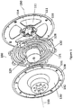
Figure 1 illustrates an exploded or expanded perspective view of the planar torque spring. Illustrated is the Applicant'snovel 3 spline torsion spring, the sensor disk mounting bracket and the input side sensor disk. Also shown is the outside circumferential edge of the output side sensor disk protruding from the output bracket and support ring. Also illustrated is the load bearing torsion spring support. It will be appreciated that the sensor disks is not within the load path. Also shown is the axis of rotation. - .
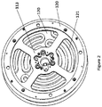
Figure 2 illustrates a reverse view of a portion illustrated inFigure 1 . Illustrated is the sensor disk mounting bracket, and the torsion spring(behind the sensor disk mounting bracket). The input side sensor disk is not shown. - .
Figure 3 illustrates a perspective view of the torsion spring within the output bracket, output bracket support ring, the edge of the first and second sensor disks and one stationary sensor (input sensor) load bearing cap that connects to the input side of the torsion spring. This cap attaches to the opposite side of the torsion spring from the frame described asFigure 2 . - .
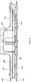
Figure 4 is a side view of the assembly containing the planar torsion spring. Illustrated is the torsion spring and the first sensor disk (input side) and second sensor disk (output side). Also illustrated output bracket, output bracket support ring. Also illustrated is the load bearing torsion spring support (and its location within the output support bracket). Note the stationary sensors are not shown. The inside surface of the load bearing plate may have an offset to prevent the inside surface touching the torsion spring. - .
Figure 5 is an illustrated flow chart for the disclosure. - The Applicant's disclosure incorporates an planar torsion spring. The disclosure utilizes sensors having the ability to measure the angular deflection of either the input side or output side of the planar torsion spring. Such deflection result from an applied load.
- This can be one angular measurement sensor that has both the stationary side (stator) and moving side (rotor) mounted (outside of the load path) to the input and output sides of the spring respectively. The preferred embodiment has two angular measurement sensors with rotors or sensor disks attached to both the input and output sides of the spring. There are complementary stationary sensors (stators) each mounted to the non-moving reference frame.
- In the single sensor embodiment, the deflection of the spring is directly measured by the angle sensor (sensor disks) and multiplied by the spring constant to ascertain the torque.
- In the preferred embodiment, two or more angle sensors (sensor disks) measures the angle formed between the position of the torsion spring to its respective side in the non-moving reference frame. The torque is then calculated by multiplying the difference between the output and input angle sensors by the spring constant. In either case, it is imperative that the sensor rotors are mounted outside of the load path of the spring in order to minimize hysteresis.
- In one embodiment of the Applicant's disclosure, the sensor disks can be translucent, e.g., clear plastic or polymer. In other embodiments, the sensor disks can be metal, plastic or other material that can be machined or molded. In one embodiment, the sensor disks can contain a circumferential band of tick marks. The degree markings (or partial degree markings) can be opaque. In this embodiment, the opaque tick marks are detectable by the stationary sensor. The tick marks on the sensor disk are positioned to pass in front of the stationary sensor. In another embodiment, the sensor disk markings can be electromagnetic which can be detected by the stationary sensor.
- The Applicant's disclosure teaches a very high degree of resolution regarding the position of the planar torsion spring. In one embodiment described in part in the preceding paragraph, there were 120,000 tick discrete detectable marks on each sensor disk. As will be appreciated the marks are detected by the stationary sensor.
- The Applicant's design requires a method of measuring angular position of the input and output sides of the torsion spring wherein the measuring device is mounted outside of the load path. These devices could be incremental encoders, absolute position sensors (inductive, capacitive, optical), or resolvers. It is important that the angles measured by the sensors are differenced and multiplied by the spring constant of the torsion spring to compute the torque applied and that the measuring devices are mounted outside of the load path.
- In one embodiment shown and described herein, the detectable marks (sometimes referred to as tick marks) are place on the edge of the sensor disk. It will be appreciated that the marks can be placed elsewhere on the sensor disk. Placement would be in a circular pattern around the axis of rotation. The stationary sensor would be positioned on a stator or other stationary, non load bearing component. The stationary sensor is not in contact with the sensor disk.
- As used herein, the load path is simply the direction in which each consecutive load will pass through connected members. As stated, the sensor disks and the stationary sensors are not within the load path of the torsion spring or interconnected components. As described and illustrated in the Figures, the stationary sensor is connected only to a stationary structure. The stationary sensor is not interconnected with any other component. Similarly, the sensor disk is connected only to torsion spring. The sensor disk is not interconnected with any other component. As described further, the sensor disk and stationary sensor, although perhaps positioned in close proximity, are not interconnected. It will be appreciated that the torsion spring can be connected to other movable structural members such a gear or motor shaft. However such additional members are not subject of this disclosure and accordingly not described. The additional components may also be varied depending upon the application of the torsion spring.
- As described in greater detail below, each sensor disk is attached to the torsion spring. One sensor disk is attached to the torsion spring input side (inner ring). The other disk (positioned on the opposite side of the torsion spring) is attached to the output side (outer ring) of the planar torsion spring. Each respective sensor disk rotates or moves with the rotation spring of the applicable side of the spring.
- Specifically, movement of the input side of the torsion spring will cause movement of the sensor disk attached to the torsion spring input. This movement can be the result of torque (or "load") being applied to one side of the planar torsion spring. If torque is applied to the input side of the planar torsion spring, this will cause movement of the first sensor disk (the disk attached to the input side of the spring). This movement of the sensor disk will be detected by the input sensor, i.e., the combination of markers on the sensor disk and the stationary sensor. It will be recalled that the input sensor is in a fixed position and does not rotate with the torsion spring or sensor disk. The stationary sensor may be mounted on a stationary structure independent of the rotational movement of the sensor disks or the torque load on the planar torsion spring. Also the sensor disk is outside the load path. It will not be directly affected by the addition of torque on the spring. The sensor disk moves only in passive reaction to the rotation of the planar torsion spring.
- Similarly the sensor disk (sensor rotor) attached to the output side of the torsion spring (outer ring) rotates with the planar torsion spring. Movement of the output side of the torsion spring (regardless of the absence of movement of the input side) will be detected by the output sensor component discussed above. The stationary sensor (stator) is fixed to a non-moving or stationary structure of the elastic torque sensor. Neither the sensor disk or sensor component is part of the load path.
- In one embodiment, one subcomponent of the stationary sensor will shine a light beam across and through the transparent sensor disk. See paragraph [0019] above. The light beam will be detected by the second subcomponent of the stationary sensor (a light receiver). When an opaque degree marking crosses the light path, the light sensor component will detect an interruption in signal. This will cause the sensor to send a signal. The sensor may send the signal to a CPU, microprocessor, controller or similar devices. Such device may calculate the amount of movement of spring, the degree of deflection of the output side relative to the input side, the angular movement, the position of the planar torsion spring, the speed of rotation and the resulting hysteresis. The stationary sensor will also signal the number of tick marks passing per unit of time. This information can also be communicated to the programmable controller. Utilizing the spring constant of the torsion spring, the torque experienced by the spring can be calculated.
- In another embodiment, the sensor disk can have notches or teeth placed on the circumference. The position sensor would detect the interruptions in light caused by the notches or teeth rotating through the light path.
- In yet another embodiment, markings can be placed on the circumference of the output side and the input side respectively. In one embodiment, the markers can be reflective and the position sensor will detect the reflected light. This will eliminate the need for two subcomponents.
-
Figure 1 illustrates an example of atorsion spring assembly 100. The illustration is an exploded view. The planar (flat)torsion spring 120 is illustrated. (For a full view of the torsion spring and its operation, reference is made to Applicant's application14/792,882 filed July 7, 2015 rotation 150. This axis ofrotation 150 is shared with the outer ring 128 (the output side). The inner ring is not visible inFigure 1 . (The inner ring is covered by the load bearingtorsion spring support 129.) A portion of thesplines 121 is shown. It will be appreciated that the spline joins both the outer ring (spring output side) and the inner ring (the spring input side). Theouter circumference 119 of thefirst sensor disk 111 is also shown. The full view of the first sensor disk is hidden by thesensor support bracket 114. The first sensor disk rotates with movement of the input side. A portion of thefirst sensor disk 111 is visible between the radial portion of the support bracket. The entire disk may be translucent with the exception of the tick marks (which may be used in one embodiment of the disclosure). The sensor disk is not within the load path experienced by the torsion spring - Also illustrated in
Figure 1 is theouter edge 139 of thesecond sensor disk 131. This outer edge can be the location of the tick marks in some embodiments of the disclosure. This is the sensor disk attached to the spring output side. Thesecond sensor disk 131 is held in place between theoutput bracket 130 andsupport ring 132. The second sensor disk passively rotates with movement of the output side of thetorsion spring 120. Stated differently, the sensor disk is not connected to any component other than on a side (input or output) of the torsion spring. Theouter edge 139 of thesecond sensor disk 131 turns or rotates with the rotation of the planar torsion spring. As will be disclosed later, the edge of the sensor disk can rotate through an opening or proximate to the side of a stationary sensor. The stationary sensor can detect various types of marks on, for example, the edge of the sensor disk. - As previously disclosed, the splines connect the input side with the
output side 128. The elasticity of the splines permits the output side or input side to rotate relative to the respective input side or output side. -
Figure 2 illustrates the non-load bearing sensordisk mounting bracket 114. Behind the mounting bracket is thetorsion spring 120. Also shown is a partial view thesplines 121. Thin torsion spring input is hidden behind thecenter junction 113 of thedisk mounting bracket 114. The second sensor disk is attached to the output side (110 ofFigure 1 ). - Each sensor can be thought of consisting of two components. The first component is the sensor disk (sometimes referred to a rotor disk) described above. The second stationary sensor is a device positioned on a stationary structure of the elastic torque sensor. This second sensor disk (like the first sensor disk,) also is not within the load path. The second sensor component (sensor disk and stationary sensor) may utilize optical, capacitive, magnetic properties or any other system known to persons skilled in the art.
-
Figure 3 is another view of the torsion spring configuration. Illustrated is astationary plate 161. This structural element is not load bearing. Shown attached to this structure is astationary sensor 160. This sensor interacts with thefirst sensor disk 111. This sensor disk is attached to the input side of the spring. Note that the stationary sensor fits over the circumferential edge of the sensor disk. The two components are not in contact. The rotation of the sensor disk, coupled with the rotation of the torsion spring under load, is not impeded. - Also shown in
Figure 3 is the exposed edge of thesecond sensor disk 131. The stationary sensor for this disk is not shown. Illustrated is thesupport ring 132 and theoutput bracket 130. Also illustrated are other components which may be used in an embodiment of the invention. These are a bearingfixture 172 andbearings 171. The axis ofrotation 150 is also illustrated. -
Figure 4 illustrates a side view of the device subject of the disclosure. Illustrated is an edge view of thefirst sensor disk 111 and thesecond sensor disk 131. Also illustrated is an edge view of thetorsion spring 120. Note thespaces torsion spring support 129 which fits within theoutput bracket 130. Also show is thecircular ring 132 holding theoutput sensor disk 131 to theoutput bracket 130. -
Figure 5 illustrates a logic flow diagram of the operation of the stationary sensor with the sensor disk and a possible controller, microprocessor or CPU, etc., in conjunction with the movement of the output sensor. The stationary sensor can emit a signal at a rate of at least 10 kilohertz (10,000 cycles/sec). In one embodiment the signal is a pulse of light. The light pulse monitors the position of the input side of the sensor disk (Step 1). In another embodiment, the light source is continuous. If the stationary sensor detects a change in signal, either an interruption of the light signal received by the stationary sensor or receipt of a light source, the sensor detects rotational movement of the input side. A signal will be sent to the computer processor or controller (Step 4). The rotational angle can be detected. The amount of force can be computed using the spring constant. (Step 6). - The number of light signal interruptions can be detected by the stationary sensor and counted by the computer processor (
Step 4 and 9). In one embodiment, the number of interruptions correlates to the number of tick marks on the circumference of the sensor disk attached to the output side. The number of ticks correlates to the distance of the circumference traversing across the encoder receiver. This correlates to the number of degrees of the arc segment. The length of the arc is calculated by the computer processor. Knowing the spring constant, the amount of force experienced by the output side can be calculated (Step 8). - Simultaneously, a separate stationary sensor monitors the output side (Step 7). If movement is detected, the receiver submits a signal of the number of light interruptions (or light reflections if reflective markers are used) to the computer processor and the processor calculates the force based upon the amount of movement and spring constant (Step 9).
- The controller can compare the calculated measurements of force on the output side and on the input side and measure the difference in position of the output side and the input side, multiply the difference by the spring constant and measure the applied torque. (Step 10)
- The process is repeated for the next time interval. In the preferred embodiment, the time interval is at least 1/1x10-5 second. (Step 8). If movement is detected, the movement is measured from the previous read position (Step 3). The force is calculated based upon the movement to the new position. (
Step 5 and 8).Steps 2 through 10 are repeated. - In a preferred embodiment, a stationary sensor (encoder) transmits a light signal through the sensor disk attached to the input side of the planar torsional spring. The light is transmitted through the translucent disk to an stationary sensor receiver subcomponent on the opposite side of the disk. As discussed previously, the circumference of the disk is marked with opaque tick marks. These marks interrupt the light signal as the input side moves through the light signal. The interruptions are detected by the stationary sensor receiver subcomponent. The receiver can transmits a signal of the interruption to a computer processor, etc. The computer processor can calculate the distance rotated by the disk.
- In
step 5 the computer processor computes the rotational movement based upon the signals received from the stationary sensor receiver subcomponent. Using the known spring constant, the computer processor calculates the force experienced by the input side (Steps 10 and 11). Simultaneously, signals from the stationary sensor monitoring the sensor disk attached to the output side. These signals can be used by the computer processor to ascertain whether the output side has moved (Step 5). - If movement is detected, the amount of rotation is calculated by the computer processor based upon the signals received from the stationary sensor receiver subcomponent (
Steps 8 and 9). The amount of force experienced on the output side can be calculated based upon the amount of deflection and the spring constant. This computed force can be reconciled with the value computed inStep 10 above. - In an embodiment, the computer processor can compute the amount of offset force that could be generated by a torque force generator.
- It will be appreciated that the sensors, both the stationary sensor signal transmitter subcomponent and signal receiver subcomponent are not affixed to the planar torsion spring. These sensors, that may be in communication with the computer processor or microprocessor, are independently mounted to frame or similar structure of the device and are not in the load path experienced by the output side or input side of the torsion spring.
- Alternate sensor mechanisms can include a resolver, i.e., an analog encoder that converts an angle into a voltage level that can be read by an analog digital converter (ADC), or an Absolute Position Sensor (APS) that provides an exact angle based on a fixed zero point. In one embodiment, the sensor utilizes an incremental encoder. The incremental encoder requires a startup step of positioning the output and input sides each time the spring is activated.
- In one embodiment, the stationary sensor component may be an optical encoder attached to a stationary structure and can transmit an optical signal to a reader sensor subcomponent on the opposite side of the transparent sensor disk circumference. (It will be appreciated that in an embodiment of the disclosure, there will be two sensor disks. The first sensor disk is attached to the input side of the planar torsion spring. The second sensor disk is attached to the output side of the planar torsion disk. Both sensor disks rotate with the input or output side of the torsion spring respectively. Both sensor disks are not in the load path.)
- The sensor disk, in one embodiment, is translucent thereby allowing the optical signal to be transmitted through the disk and to the reader of the encoder (subcomponent of the second sensor component). The tick marks positioned on the sensor disk are opaque, thereby blocking the optical signal as, for example, the output side rotates in response to torque. This causes an interruption of the signal received by the read head of the sensor. This signal can be transmitted to a computer processer, microprocessor or other device. The same mechanism applies for rotation of the input side with its attached sensor disk.
- It will be appreciated that the output side and input side have an opportunity for limited independent rotation. For example, the output side of the torsion spring may move (rotate) without movement (rotation) of the input side of the torsion spring. This movement (and lack of movement) will be reflected in movement of the sensor disks. The movement of the ticks located on the circumference of a sensor disk will be detected by the position sensor. This may cause a signal to be emitted from one or both position sensors. (As already discussed, the detectible markers are not limited to be located proximate or on the circumference of the sensor disk. In one alternate embodiment, the markers on the sensor disk may have electromagnetic properties that produce a signal within the stationary sensor as each marker passes proximate to the stationary sensor.)
- Torque is calculated by multiplying the difference between the output position and input position sensors by the known spring constant for the material and design of the torsion spring. It is the difference between the angle measurements (of the output position and input position) that relates to the torque being applied.
- This independent movement of the output side and the input side creates distortion in the shape of the planar torsion spring. This distortion is particular noted in the splines. Since, as stated repeatedly in this disclosure, it is important to measure the position or shape of the torsion spring. As stated, the torsion spring moves in response to the imposition of a load (or torque). When the load is removed, the torsion spring is intended to return to its original shape. Again, measurement of the position (or shape) of the inner circle (input side) relative to the outer ring (output side) is the function of the sensor disks and the stationary sensors.
- In the prior art devices, the prior art component (replaced by the Applicant's sensor disk) is in the load path of the torsion spring. As already stated, the Applicant's sensor disk is not in the load path. This has a significant advantage. The prior art mechanism, being in the load path, is distorted under the load and does not fully return to the original position when the load was removed. This is not experience by the sensor disks of the Applicant's device. This distortion of the prior art device appears as if a load is continued to be applied. In contrast, there is no mechanical interference between the sensor disk and the torsion spring, thereby removing the vast majority of the hysteresis. This allows for a more accurate measure of load applied to the torsion spring.
- The Applicant's disclosure teaches a novel configuration of sensor devices. Here, the disclosure teaches a combination of sensor disks attached to the opposing input side and output side of the torsion spring with stationary sensors. The sensor mechanisms interact with each other. Both the sensor disks and stationary sensors are outside the load path. The sensor disk, are attached to the torsion spring. The torsion spring is certainly a load bearing element. The sensor disks are not attached to anything else. They passively move with the torsion spring. Similarly, the stationary sensors are attached to structural elements of the elastic torque sensor that are also not in the load path. Not being in the load path means not being subject to the imposition of torque or load.
- Separating the torsion spring from the sensors (and positioning the sensor outside the load path) has had the unexpected benefit of decreasing the measured hysteresis of the spring. This benefit is also experienced by separating the sensor disk from the stationary sensor. The low hysteresis is due to the removal of the sensor disk (sensor rotor) and stationary attached sensor component from the load path. Removal of the sensor disks (sensor rotors) from the load path has been noted to be particularly beneficial. The Applicant's configuration has achieved hysteresis factors as low as 0.25 percent of maximum load experienced by the planar torsion spring. Typically the hysteresis factor exceeds 1 or 2 percent of the load.
- The low hysteresis due to the removal of the load path from the sensor rotor mounting allows use of lighter (less stiff) torsion springs. Low stiffness of the torsion springs was found to be a factor in using high stiffness torsion springs. However this stiffness limited the movement or deflection of the spring causing difficulty in achieving the desired high resolution.
- As previously disclosed, the above describes only one embodiment of the disclosure. Other mechanisms for monitoring the rotation of the output side or input side are subject of this disclosure. For example, in sensor disks may have notched teeth or prongs. Like the tick marks illustrated in
Figure 2 , the prongs or teeth can block the optical signal from reaching the encoder receiver. The change in the status of the receiver, i.e., receiving light changing to receiving no light, can cause a signal be sent to the computer processor. Such a signal will indicate the input side or output side has rotated. - In another embodiment, the rotational movement may be detected directly from the movement of the outer circumference of the input side or the outer circumference of the output side. For example, the circumference can be periodically marked with reflective material. Alternatively the circumference can be marked with dark (light absorptive) material. An optical encoder can be positioned to transmit a light source onto the circumference.
- In an embodiment, the computer processor can compute the amount of offset force that could be generated by a torque force generator.
- It will be appreciated that the sensors, both the stationary sensor signal transmitter subcomponent and signal receiver subcomponent are not affixed to the planar torsion spring. These sensors, that may be in communication with the computer processor or microprocessor, are independently mounted to frame or similar structure of the device and are not in the load path experienced by the output side or input side of the torsion spring.
- Alternate sensor mechanisms can include a resolver, i.e., an analog encoder that converts an angle into a voltage level that can be read by an analog digital converter (ADC), or an Absolute Position Sensor (APS) that provides an exact angle based on a fixed zero point. In one embodiment, the sensor utilizes an incremental encoder. The incremental encoder requires a startup step of positioning the output and input sides each time the spring is activated.
- This specification is to be construed as illustrative only and is for the purpose of teaching those skilled in the art the manner of carrying out the invention. It is to be understood that the forms of the disclosure herein shown and described are to be taken as the presently preferred embodiments. As already stated, various changes may be made in the shape, size and arrangement of components or adjustments made in the steps of the method without departing from the scope of the disclosure as claimed. For example, equivalent elements may be substituted for those illustrated and described herein and certain features of the disclosure maybe utilized independently of the use of other features, all as would be apparent to one skilled in the art after having the benefit of this description of the invention.
Claims (24)
- An elastic torque sensor (100) comprising:a) an elastic planar torsion spring (120) having an axis of rotation (150), an input side and an output side, wherein the elastic planar torsion spring (120) is positioned in a load path;b) the output side or the input side structured to rotate or deflect at least a portion of the elastic planar torsion spring (120) in response to a load;c) a first sensor disk (111) attached to the input side of the elastic planar torsion spring (120) and configured to move with the input side of the elastic planar torsion spring (120);d) a second sensor disk (131) attached to the output side of the elastic planar torsion spring (120) and configured to move with the output side of the elastic planar torsion spring (120);e) a first stationary sensor (160) positioned to detect movement of the first sensor disk (111) and a second stationary sensor positioned to detect movement of the second sensor disk (131);f) the first sensor disk (111), the second sensor disk (131), the first stationary sensor (160) and the second stationary sensor being positioned outside the load path of the elastic planar torsion spring (120);g) the first sensor disk (111), the second sensor disk (131), the first stationary sensor (160) and the second stationary sensor being adapted to detect rotational movement of the elastic planar torsion spring (120).
- The elastic torque sensor (100) according to claim 1, wherein the first sensor disk (111) is in contact only on an input side to the elastic planar torsion spring (120) and the second sensor disk (131) is in contact only with the output side of the elastic planar torsion spring (120).
- The elastic torque sensor (100) according to claim 1, wherein the first stationary sensor (160) is arranged to detect marks on the first sensor disk (111) wherein the first stationary sensor (160) is positioned on a stationary structure relative to the elastic planar torsion spring (120) and the second stationary sensor is arranged to detect marks on a second sensor disk (131) wherein the second stationary sensor (131) is positioned on a stationary structure relative to the elastic planar torsion spring (120).
- The elastic torque sensor (100) according to claim 1, wherein the first sensor disk (111) rotates with the rotation of a torsion spring input side in response to a load and a second sensor disk (131) attached to a torsion spring output side, wherein the second sensor disk (131) rotates with rotation of the torsion spring output side in response to a load.
- The elastic torque sensor (100) according to claim 2, wherein the first stationary sensor (160) is positioned to detect movement of the marks on the first sensor disk (111) and the second stationary sensor is positioned to detect movement of marks on the second sensor disk (131).
- The elastic torque sensor (100) according to claim 3, wherein the first stationary sensor (160) and the second stationary sensor are structured to send a signal upon detected movement of either the first sensor disk (111) or the second sensor disk (131).
- The elastic torque sensor (100) according to claim 6, further comprising a programmable controller in communication with the signal from at least one of said first sensor disk (111) and the second sensor disk (131) to calculate a difference between a position of the second sensor disk (131) and the first sensor disk (111).
- The elastic torque sensor (100) according to claim 7, wherein the programmable controller measures torque.
- The elastic torque sensor (100) according to claim 1, wherein the elastic planar torsion spring (120) is structured so either the input side or the output side can rotate relative to the other side.
- The elastic torque sensor (100) according to claim 1, further comprising at least one spline (121) connecting the elastic planar torsion spring (120) input side with the elastic planar torsion spring (120) output side.
- The elastic torque sensor (100) according to claim 6, wherein the structure of the elastic torsion spring (120) with the first sensor disk (111) and the second sensor disk (131) and the first stationary sensor (160) and the second stationary sensor structured outside the load path is adapted for achieving a hysteresis factor as low as 0.25% of a maximum load experienced by the elastic planar torsion spring (120).
- The elastic torque sensor (100) of claim 6, wherein each the first stationary sensor (160) and the second stationary sensor is structured to detect a load of approximately 0.2 N.m.
- The elastic torque sensor (100) according to claim 3, wherein either the first sensor disk (111) or the second sensor disk (131) is structured to utilize the first stationary sensor (160) or the second stationary sensor, respectively, such as at least an optical stationary angular position, an induction stationary angular position sensor reacting to movement of an electromagnetic source, a stationary angular position sensor utilizing capacitance or other known detection mechanism structure.
- The elastic torque sensor (100) according to claim 9, wherein the first sensor disk (111) and the second sensor disk (131) contain approximately 120,000 tick marks.
- The elastic torque sensor (100) according to claim 9, wherein 120,000 tick marks on a sensor enable high resolution of movement.
- The elastic torque sensor (100) of claim 11, comprising the first stationary sensor (160) and the further stationary sensor structured to detect movement of at least one between the first sensor disk (111) and the second sensor disk (131) wherein said one between the first sensor disk (111) and the second sensor disk (131) detects movement of the elastic planar torsion spring (120) having a known stiffness wherein the first sensor disk (111) and second sensor disk (131) and the first stationary sensor (160) an the further stationary sensor are structured to achieve approximately 0.2 N·m of torque resolution.
- The elastic torque sensor (100) according to claim 1, wherein:a) the input side of the elastic planar torsion spring (120) comprises a first inner ring, and the output side of the elastic planar torsion spring (120) comprises a second outer ring (128), wherein the second outer ring (128) is concentrically positioned externally to the inner ring;b) the axis of rotation (150) being shared by the first inner ring and the second outer ring (128);c) the first inner ring and the second outer ring (128) are connected by a plurality of structured deformable and elastic splines (121).
- The elastic torque sensor (100) according to claim 17, wherein the elastic torsion spring (120) comprises three splines (121), wherein each spline (121) comprises concentric arcs extending from and connecting the output side (128) to the input side of the elastic planar torsion spring (120).
- The elastic torque sensor (100) according to claim 17, wherein the elastic torque sensor is rotatable in response to a load and structured to have a hysteresis factor as low as 0.25 % of the maximum load experienced by the said elastic torque sensor (100).
- A method of measuring movement of an elastic planar torsion spring (120) in response to placement of a load on either the elastic planar torsion spring (120) input side or output side (128), comprising:a) positioning an elastic planar torsion spring (120) in a load path;b) attaching a first sensor disk (111) to an input side of the elastic planar torsion spring (120) and a second sensor disk (131) to an output side (128) of the elastic planar torsion spring (120), wherein the first sensor disk (111) and the second sensor disk (131) are mounted to structures that are not in the load path of the elastic planar torsion spring (120) and the first and second sensor disks (111, 131) rotate with the deflection or rotation of the elastic planar torsion spring (120) in response to a load, so that a load passing through the elastic planar torsion spring (120) and other interconnected components such as a gear or a motor shaft, does not pass through the first sensor disk (111) nor the second sensor disk (131);c) marking each of the first and the second sensor disks (111, 131);d) positioning the marks such that the marks reflect rotation of each of the first and second sensor disk (111, 131);e) positioning at least a first stationary sensor (160) and a further stationary sensor mounted on a stationary structure, so that the load passing through the elastic planar torsion spring (120) and other interconnected components such as a gear or a motor shaft, does not pass through the stationary sensor (160) nor the further stationary sensor; andf) structuring the first stationary sensor (160) and the further stationary sensor to detect movement of the markers.;
- The method of claim 20, further comprising sending a signal from the first stationary sensor (160) and the second stationary sensor in response to the detected movement of the elastic planar torsion spring (120) input side and output side (128).
- The method of claim 20, further comprising detecting relative movement of the elastic planar torsion spring (120) input side with respect to output side (128) in response to a change in torsional load.
- The method of claim 20, further comprising:a) differencing the angular position of the first sensor disk (111) and the second sensor disk (131) to measure a deflection of the elastic planar torsion spring (120) andb) inferring torque on the elastic planar torsion spring (120) by scaling the elastic planar torsion spring (120) deflection by the elastic planar torsion spring (120) stiffness constant.
- A method of measuring movement of an elastic planar torsion spring (120) in response to placement of a load path on either the elastic planar torsion spring (120) input side or output side (128), comprising:a) attaching a first sensor disk (111) of an input side of an elastic planar torsion spring (120) and attaching a second sensor disk (131) to an output side (128) of the elastic planar torsion spring (120), the first sensor disk (111) and the second sensor disk (131) being positioned outside the load path of the elastic planar torsion spring (120);b) positioning stationary sensors outside the load path of the elastic planar torsion spring (120), further comprising positioning the stationary sensors to detect rotational movement the first and the second sensor disks (111, 131);c) detecting movement of the elastic planar torsion spring (120) from the movement of the first and the second sensor disks (111, 131); andd) detecting the load placed on the elastic planar torsion spring (120) by calculation of the amount of deflection of the elastic planar torsion spring (120) and the elastic planar torsion spring (120) stiffness constant.
Applications Claiming Priority (7)
| Application Number | Priority Date | Filing Date | Title |
|---|---|---|---|
| US201462061815P | 2014-10-09 | 2014-10-09 | |
| US201562099191P | 2015-01-01 | 2015-01-01 | |
| US14/691,702 US9833662B2 (en) | 2014-10-09 | 2015-04-21 | Series elastic motorized exercise machine |
| US201562173498P | 2015-06-10 | 2015-06-10 | |
| US14/792,882 US20160102724A1 (en) | 2014-10-09 | 2015-07-07 | Concentric Arc Spline Rotational Spring |
| US14/809,575 US9772240B2 (en) | 2014-10-09 | 2015-07-27 | Elastic torque sensor for planar torsion spring |
| PCT/US2015/053893 WO2016057350A1 (en) | 2014-10-09 | 2015-10-03 | Elastic torque sensor for planar torsion spring |
Publications (3)
| Publication Number | Publication Date |
|---|---|
| EP3204745A1 EP3204745A1 (en) | 2017-08-16 |
| EP3204745A4 EP3204745A4 (en) | 2018-05-16 |
| EP3204745B1 true EP3204745B1 (en) | 2019-12-04 |
Family
ID=55655142
Family Applications (1)
| Application Number | Title | Priority Date | Filing Date |
|---|---|---|---|
| EP15848583.9A Active EP3204745B1 (en) | 2014-10-09 | 2015-10-03 | Elastic torque sensor for planar torsion spring |
Country Status (2)
| Country | Link |
|---|---|
| US (2) | US20160102724A1 (en) |
| EP (1) | EP3204745B1 (en) |
Families Citing this family (32)
| Publication number | Priority date | Publication date | Assignee | Title |
|---|---|---|---|---|
| FR3001267B1 (en) * | 2013-01-18 | 2015-08-21 | Thales Sa | SUSPENSION ELEMENT FOR THE MECHANICAL CONNECTION OF A SUSPENDED LOAD IN A SUPPORT |
| CN104514828B (en) * | 2013-09-30 | 2016-06-08 | 珠海格力节能环保制冷技术研究中心有限公司 | Flat spring and plate spring groups and compressor |
| EP3283785B1 (en) | 2015-04-15 | 2019-12-25 | Pumpkin Mounts, Llc | An improved mounting |
| USRE49567E1 (en) | 2015-05-21 | 2023-07-04 | Russo Trading Company, Inc. | Tile lippage post |
| USD862204S1 (en) | 2015-05-21 | 2019-10-08 | Russo Trading Company, Inc. | Lippage cap |
| USD834922S1 (en) | 2015-05-21 | 2018-12-04 | Russo Trading Company, Inc. | Threaded lippage cap |
| USD856111S1 (en) | 2015-05-21 | 2019-08-13 | Russo Trading Company, Inc. | Tile lippage threaded post |
| US10364858B2 (en) | 2015-07-23 | 2019-07-30 | Rethink Robotics Gmbh | Planar flexure members and actuators using them |
| US9556920B1 (en) * | 2015-07-23 | 2017-01-31 | Rethink Robotics, Inc. | Planar flexure members and actuators using them |
| CN105909727A (en) * | 2016-06-29 | 2016-08-31 | 吉林大华机械制造有限公司 | Torsional vibration isolation connection disk |
| USD830161S1 (en) * | 2016-11-04 | 2018-10-09 | Russo Trading Company, Inc. | Orientation washer |
| US10293481B1 (en) * | 2016-12-14 | 2019-05-21 | The United States Of America As Represented By The Administrator Of The National Aeronautics And Space Administration | Relative deflection detector |
| USD817753S1 (en) * | 2017-03-09 | 2018-05-15 | Woodward, Inc. | Spring array |
| USD821863S1 (en) * | 2017-05-22 | 2018-07-03 | J. Juan, S.A. | Washer |
| US10066812B1 (en) | 2017-05-23 | 2018-09-04 | Axis Lighting Inc. | Rotational couplers for light fixtures |
| USD835979S1 (en) * | 2017-06-09 | 2018-12-18 | Simpson Strong-Tie Company Inc. | Decorative washer |
| US10830654B2 (en) * | 2017-08-25 | 2020-11-10 | Flexiv Ltd. | Robust torque sensor with moderate compliance |
| WO2019052950A1 (en) * | 2017-09-18 | 2019-03-21 | Tetra Laval Holdings & Finance S.A. | A welding head |
| NL2021908B1 (en) * | 2018-10-31 | 2020-05-14 | Truekinetix B V | A torque sensing system |
| US20220003618A1 (en) | 2018-10-02 | 2022-01-06 | Truekinetix B.V. | Torque sensing system |
| TWI668381B (en) * | 2018-11-19 | 2019-08-11 | 國立成功大學 | Planar spring and rotating series elastic actuator |
| TWI663813B (en) * | 2018-11-28 | 2019-06-21 | 財團法人工業技術研究院 | Output torque caculation device and caculation method thereof |
| EP3671141B1 (en) * | 2018-12-20 | 2022-08-03 | Bizerba SE & Co. KG | Load cell and weighing foot |
| US11085838B2 (en) * | 2019-03-10 | 2021-08-10 | Ati Industrial Automation, Inc. | Force/torque sensor having serpentine or coiled deformable beams and overload beams |
| WO2020204234A1 (en) * | 2019-04-05 | 2020-10-08 | (주)로보티즈 | Elastic body having variable rigidity, and actuator module including same |
| KR20210082935A (en) | 2019-12-26 | 2021-07-06 | 엘지전자 주식회사 | Series elastic actuator |
| KR20210082920A (en) * | 2019-12-26 | 2021-07-06 | 엘지전자 주식회사 | Series elastic actuator |
| US11987987B2 (en) * | 2020-06-13 | 2024-05-21 | Charles Porter | Insert for a panel |
| EP4291129A1 (en) | 2021-02-11 | 2023-12-20 | MAKO Surgical Corp. | Robotic manipulator comprising isolation mechanism for force/torque sensor |
| EP4202251A1 (en) * | 2021-12-23 | 2023-06-28 | Maxon International AG | Level torsion spring for a series elastic actuator |
| US20230349442A1 (en) * | 2022-04-28 | 2023-11-02 | Raytheon Company | Shock isolator with flexures and stop mechanism |
| DE102022128021A1 (en) | 2022-10-24 | 2024-04-25 | Marquardt Gmbh | Leaf spring |
Family Cites Families (36)
| Publication number | Priority date | Publication date | Assignee | Title |
|---|---|---|---|---|
| US4235437A (en) | 1978-07-03 | 1980-11-25 | Book Wayne J | Robotic exercise machine and method |
| CA1222782A (en) | 1982-06-01 | 1987-06-09 | Jim Mcarthur | Multi-mode exercising apparatus |
| US4569518A (en) | 1983-02-16 | 1986-02-11 | Fulks Kent B | Programmable exercise system |
| US4872767A (en) * | 1985-04-03 | 1989-10-10 | General Electric Company | Bearing support |
| JPS61240133A (en) * | 1985-04-18 | 1986-10-25 | Hidehiro Yoshino | Torque detector |
| US5117170A (en) | 1985-12-23 | 1992-05-26 | Life Fitness | Motor control circuit for a simulated weight stack |
| US4828257A (en) | 1986-05-20 | 1989-05-09 | Powercise International Corporation | Electronically controlled exercise system |
| US4778175A (en) | 1986-09-02 | 1988-10-18 | The Toro Company | Electronic control of resistance force for exercise machine |
| US5020794A (en) | 1987-01-16 | 1991-06-04 | Bally Manufacturing Corporation | Motor control for an exercise machine simulating a weight stack |
| US4792708A (en) * | 1987-11-23 | 1988-12-20 | Hr Textron, Inc. | Force motor, multiple, parallel element linear suspension |
| US4811946A (en) | 1988-03-18 | 1989-03-14 | Pelczar Stanley J | Weight lifting apparatus |
| US4930770A (en) | 1988-12-01 | 1990-06-05 | Baker Norman A | Eccentrically loaded computerized positive/negative exercise machine |
| JPH0646738Y2 (en) * | 1989-04-17 | 1994-11-30 | 株式会社三ツ葉電機製作所 | Rotational position detector |
| CA2164096A1 (en) | 1993-06-02 | 1994-12-08 | Ted R. Ehrenfried | Electromechanical resistance exercise apparatus |
| EP0702582A4 (en) | 1993-06-02 | 1997-09-03 | Ted R Ehrenfried | Aerobic strength apparatus |
| US5919115A (en) | 1994-10-28 | 1999-07-06 | The Regents Of Theuniversity Of California | Adaptive exercise machine |
| US5993356A (en) | 1996-12-31 | 1999-11-30 | Houston Enterprises, Inc. | Force generation and control system for an exercise machine |
| TW322157U (en) * | 1997-05-21 | 1997-12-01 | Xin-Zong Zhang | Detecting device capable of detecting both speed and torsion at the same time |
| CA2347796C (en) * | 1998-10-30 | 2009-12-29 | Vernon A. Lambson | Method and apparatus for measuring torque |
| US6170162B1 (en) * | 1999-05-27 | 2001-01-09 | Sarcos, L.C. | Rotary displacement system using differential measuring |
| US7237444B2 (en) * | 2005-06-29 | 2007-07-03 | Freudenberg-Nok General Partnership | Torque cell for determining a torque load on a rotary member |
| US20070079315A1 (en) * | 2005-10-05 | 2007-04-05 | Gregor Mittersinker | Hybrid turntable |
| EP1933948A4 (en) | 2005-10-12 | 2013-04-24 | Sensyact Ab | A method, a computer program and a device for controlling a movable resistance element in a training device |
| DE102006052832B4 (en) * | 2006-05-05 | 2011-07-21 | Lumberg Connect GmbH, 58579 | Meander spring for arrangement between two elements |
| ITUD20080139A1 (en) * | 2008-06-19 | 2009-12-20 | Tonutti Tecnoagricola S R L | DISK FOR DOSING AND SINGLE SELECTION OF SEEDS, DOSAGE AND TRANSPORT GROUP FOR DISTANCE REMOVAL INCLUDING SUCH DISC AND PROCEDURE FOR DOSING, SINGLE SELECTION AND DISTANCE SEED TRANSPORT |
| US8291788B2 (en) | 2009-09-22 | 2012-10-23 | GM Global Technology Operations LLC | Rotary series elastic actuator |
| US9157497B1 (en) * | 2009-10-30 | 2015-10-13 | Brigham Young University | Lamina emergent torsional joint and related methods |
| JP2011169446A (en) * | 2010-02-22 | 2011-09-01 | Mitsumi Electric Co Ltd | Plate spring and lens driving device |
| EP2364737A1 (en) * | 2010-03-08 | 2011-09-14 | Fresenius Kabi Deutschland GmbH | Drive system |
| US20120053014A1 (en) | 2010-09-01 | 2012-03-01 | Zhengmao Zhu | Apparatus and System for a Resistance Training System |
| WO2014022600A1 (en) | 2012-07-31 | 2014-02-06 | John Bird | Resistance apparatus, system, and method |
| ITRM20120482A1 (en) | 2012-10-09 | 2014-04-10 | Uni Campus Bio Medico Di Rom A | ROBOTIC DEVICE FOR ASSISTANCE AND REHABILITATION OF LOWER LIMBS. |
| DE102013021181A1 (en) * | 2012-12-20 | 2014-06-26 | Infineon Technologies Ag | torque sensor |
| US8960655B2 (en) * | 2013-05-31 | 2015-02-24 | Sunpower, Inc. | Compact flexure bearing spring for springing multiple bodies |
| CN104514828B (en) * | 2013-09-30 | 2016-06-08 | 珠海格力节能环保制冷技术研究中心有限公司 | Flat spring and plate spring groups and compressor |
| US9850814B2 (en) * | 2014-02-19 | 2017-12-26 | United Technologies Corporation | Annular spring for a bearing assembly of a gas turbine engine |
-
2015
- 2015-07-07 US US14/792,882 patent/US20160102724A1/en not_active Abandoned
- 2015-07-27 US US14/809,575 patent/US9772240B2/en active Active
- 2015-10-03 EP EP15848583.9A patent/EP3204745B1/en active Active
Non-Patent Citations (1)
| Title |
|---|
| None * |
Also Published As
| Publication number | Publication date |
|---|---|
| US9772240B2 (en) | 2017-09-26 |
| US20160116353A1 (en) | 2016-04-28 |
| EP3204745A4 (en) | 2018-05-16 |
| EP3204745A1 (en) | 2017-08-16 |
| US20160102724A1 (en) | 2016-04-14 |
Similar Documents
| Publication | Publication Date | Title |
|---|---|---|
| EP3204745B1 (en) | Elastic torque sensor for planar torsion spring | |
| CN104704336B (en) | The dynamical balancing method and device of rotary body | |
| WO2016057350A1 (en) | Elastic torque sensor for planar torsion spring | |
| CN101443985B (en) | Linear actuator | |
| US11054282B2 (en) | Magnetic position sensor for sensing position of a revolute joint | |
| CN108700410B (en) | Position detection device, method and rotation system | |
| JP3460351B2 (en) | Position detecting device and position detecting method | |
| US7456629B2 (en) | Rotary angle sensing system | |
| US9366523B2 (en) | Rotation angle sensor | |
| WO2017198220A1 (en) | Robot, and rotation measurement apparatus and method | |
| US4446746A (en) | Torque detecting apparatus | |
| WO2018195053A1 (en) | Methods and systems for measuring parameters of rotating shafts and couplings | |
| US10969251B2 (en) | Calibrating position sensor readings | |
| US20180328763A1 (en) | Rotary encoder | |
| CN101726241A (en) | Angle transducer | |
| WO2008106580A1 (en) | Linear position sensor | |
| US11359907B2 (en) | Magnetic position sensor mounting arrangement | |
| EP2546613B1 (en) | Method for working out the eccentricity and the angular position of a rotating element and Device for carrying out such a method | |
| US20150362387A1 (en) | Method and device for determining a torque applied upon a rotary body that can be driven about an axis of rotation | |
| WO2005075935A1 (en) | Sensor assembly | |
| JP5678642B2 (en) | Torque sensor and driving device | |
| EP2602627A1 (en) | Speed sensor wheel with asymmetry for determining direction of rotation | |
| JPS60231113A (en) | Incremental type rotary encoder | |
| TW202424365A (en) | Axial-radial sliding bearing with protractor | |
| KR20060019826A (en) | A uniformity machine with tire diameter measurement |
Legal Events
| Date | Code | Title | Description |
|---|---|---|---|
| STAA | Information on the status of an ep patent application or granted ep patent |
Free format text: STATUS: THE INTERNATIONAL PUBLICATION HAS BEEN MADE |
|
| PUAI | Public reference made under article 153(3) epc to a published international application that has entered the european phase |
Free format text: ORIGINAL CODE: 0009012 |
|
| STAA | Information on the status of an ep patent application or granted ep patent |
Free format text: STATUS: REQUEST FOR EXAMINATION WAS MADE |
|
| 17P | Request for examination filed |
Effective date: 20170509 |
|
| AK | Designated contracting states |
Kind code of ref document: A1 Designated state(s): AL AT BE BG CH CY CZ DE DK EE ES FI FR GB GR HR HU IE IS IT LI LT LU LV MC MK MT NL NO PL PT RO RS SE SI SK SM TR |
|
| AX | Request for extension of the european patent |
Extension state: BA ME |
|
| DAV | Request for validation of the european patent (deleted) | ||
| DAX | Request for extension of the european patent (deleted) | ||
| A4 | Supplementary search report drawn up and despatched |
Effective date: 20180416 |
|
| RIC1 | Information provided on ipc code assigned before grant |
Ipc: G01L 3/14 20060101AFI20180410BHEP Ipc: G01L 5/22 20060101ALI20180410BHEP Ipc: F16F 1/02 20060101ALI20180410BHEP Ipc: G01B 11/16 20060101ALI20180410BHEP |
|
| STAA | Information on the status of an ep patent application or granted ep patent |
Free format text: STATUS: EXAMINATION IS IN PROGRESS |
|
| 17Q | First examination report despatched |
Effective date: 20190130 |
|
| GRAP | Despatch of communication of intention to grant a patent |
Free format text: ORIGINAL CODE: EPIDOSNIGR1 |
|
| STAA | Information on the status of an ep patent application or granted ep patent |
Free format text: STATUS: GRANT OF PATENT IS INTENDED |
|
| INTG | Intention to grant announced |
Effective date: 20190716 |
|
| GRAS | Grant fee paid |
Free format text: ORIGINAL CODE: EPIDOSNIGR3 |
|
| GRAA | (expected) grant |
Free format text: ORIGINAL CODE: 0009210 |
|
| STAA | Information on the status of an ep patent application or granted ep patent |
Free format text: STATUS: THE PATENT HAS BEEN GRANTED |
|
| AK | Designated contracting states |
Kind code of ref document: B1 Designated state(s): AL AT BE BG CH CY CZ DE DK EE ES FI FR GB GR HR HU IE IS IT LI LT LU LV MC MK MT NL NO PL PT RO RS SE SI SK SM TR |
|
| REG | Reference to a national code |
Ref country code: GB Ref legal event code: FG4D |
|
| REG | Reference to a national code |
Ref country code: CH Ref legal event code: EP |
|
| REG | Reference to a national code |
Ref country code: AT Ref legal event code: REF Ref document number: 1209972 Country of ref document: AT Kind code of ref document: T Effective date: 20191215 |
|
| REG | Reference to a national code |
Ref country code: DE Ref legal event code: R096 Ref document number: 602015043178 Country of ref document: DE |
|
| REG | Reference to a national code |
Ref country code: IE Ref legal event code: FG4D |
|
| REG | Reference to a national code |
Ref country code: NL Ref legal event code: FP |
|
| REG | Reference to a national code |
Ref country code: LT Ref legal event code: MG4D |
|
| PG25 | Lapsed in a contracting state [announced via postgrant information from national office to epo] |
Ref country code: FI Free format text: LAPSE BECAUSE OF FAILURE TO SUBMIT A TRANSLATION OF THE DESCRIPTION OR TO PAY THE FEE WITHIN THE PRESCRIBED TIME-LIMIT Effective date: 20191204 Ref country code: BG Free format text: LAPSE BECAUSE OF FAILURE TO SUBMIT A TRANSLATION OF THE DESCRIPTION OR TO PAY THE FEE WITHIN THE PRESCRIBED TIME-LIMIT Effective date: 20200304 Ref country code: LT Free format text: LAPSE BECAUSE OF FAILURE TO SUBMIT A TRANSLATION OF THE DESCRIPTION OR TO PAY THE FEE WITHIN THE PRESCRIBED TIME-LIMIT Effective date: 20191204 Ref country code: NO Free format text: LAPSE BECAUSE OF FAILURE TO SUBMIT A TRANSLATION OF THE DESCRIPTION OR TO PAY THE FEE WITHIN THE PRESCRIBED TIME-LIMIT Effective date: 20200304 Ref country code: GR Free format text: LAPSE BECAUSE OF FAILURE TO SUBMIT A TRANSLATION OF THE DESCRIPTION OR TO PAY THE FEE WITHIN THE PRESCRIBED TIME-LIMIT Effective date: 20200305 Ref country code: LV Free format text: LAPSE BECAUSE OF FAILURE TO SUBMIT A TRANSLATION OF THE DESCRIPTION OR TO PAY THE FEE WITHIN THE PRESCRIBED TIME-LIMIT Effective date: 20191204 Ref country code: SE Free format text: LAPSE BECAUSE OF FAILURE TO SUBMIT A TRANSLATION OF THE DESCRIPTION OR TO PAY THE FEE WITHIN THE PRESCRIBED TIME-LIMIT Effective date: 20191204 |
|
| PG25 | Lapsed in a contracting state [announced via postgrant information from national office to epo] |
Ref country code: HR Free format text: LAPSE BECAUSE OF FAILURE TO SUBMIT A TRANSLATION OF THE DESCRIPTION OR TO PAY THE FEE WITHIN THE PRESCRIBED TIME-LIMIT Effective date: 20191204 Ref country code: RS Free format text: LAPSE BECAUSE OF FAILURE TO SUBMIT A TRANSLATION OF THE DESCRIPTION OR TO PAY THE FEE WITHIN THE PRESCRIBED TIME-LIMIT Effective date: 20191204 |
|
| PG25 | Lapsed in a contracting state [announced via postgrant information from national office to epo] |
Ref country code: AL Free format text: LAPSE BECAUSE OF FAILURE TO SUBMIT A TRANSLATION OF THE DESCRIPTION OR TO PAY THE FEE WITHIN THE PRESCRIBED TIME-LIMIT Effective date: 20191204 |
|
| PG25 | Lapsed in a contracting state [announced via postgrant information from national office to epo] |
Ref country code: PT Free format text: LAPSE BECAUSE OF FAILURE TO SUBMIT A TRANSLATION OF THE DESCRIPTION OR TO PAY THE FEE WITHIN THE PRESCRIBED TIME-LIMIT Effective date: 20200429 Ref country code: EE Free format text: LAPSE BECAUSE OF FAILURE TO SUBMIT A TRANSLATION OF THE DESCRIPTION OR TO PAY THE FEE WITHIN THE PRESCRIBED TIME-LIMIT Effective date: 20191204 Ref country code: RO Free format text: LAPSE BECAUSE OF FAILURE TO SUBMIT A TRANSLATION OF THE DESCRIPTION OR TO PAY THE FEE WITHIN THE PRESCRIBED TIME-LIMIT Effective date: 20191204 Ref country code: CZ Free format text: LAPSE BECAUSE OF FAILURE TO SUBMIT A TRANSLATION OF THE DESCRIPTION OR TO PAY THE FEE WITHIN THE PRESCRIBED TIME-LIMIT Effective date: 20191204 Ref country code: ES Free format text: LAPSE BECAUSE OF FAILURE TO SUBMIT A TRANSLATION OF THE DESCRIPTION OR TO PAY THE FEE WITHIN THE PRESCRIBED TIME-LIMIT Effective date: 20191204 |
|
| PG25 | Lapsed in a contracting state [announced via postgrant information from national office to epo] |
Ref country code: SM Free format text: LAPSE BECAUSE OF FAILURE TO SUBMIT A TRANSLATION OF THE DESCRIPTION OR TO PAY THE FEE WITHIN THE PRESCRIBED TIME-LIMIT Effective date: 20191204 Ref country code: SK Free format text: LAPSE BECAUSE OF FAILURE TO SUBMIT A TRANSLATION OF THE DESCRIPTION OR TO PAY THE FEE WITHIN THE PRESCRIBED TIME-LIMIT Effective date: 20191204 Ref country code: IS Free format text: LAPSE BECAUSE OF FAILURE TO SUBMIT A TRANSLATION OF THE DESCRIPTION OR TO PAY THE FEE WITHIN THE PRESCRIBED TIME-LIMIT Effective date: 20200404 |
|
| REG | Reference to a national code |
Ref country code: DE Ref legal event code: R097 Ref document number: 602015043178 Country of ref document: DE |
|
| REG | Reference to a national code |
Ref country code: AT Ref legal event code: MK05 Ref document number: 1209972 Country of ref document: AT Kind code of ref document: T Effective date: 20191204 |
|
| PLBE | No opposition filed within time limit |
Free format text: ORIGINAL CODE: 0009261 |
|
| STAA | Information on the status of an ep patent application or granted ep patent |
Free format text: STATUS: NO OPPOSITION FILED WITHIN TIME LIMIT |
|
| PG25 | Lapsed in a contracting state [announced via postgrant information from national office to epo] |
Ref country code: DK Free format text: LAPSE BECAUSE OF FAILURE TO SUBMIT A TRANSLATION OF THE DESCRIPTION OR TO PAY THE FEE WITHIN THE PRESCRIBED TIME-LIMIT Effective date: 20191204 |
|
| 26N | No opposition filed |
Effective date: 20200907 |
|
| PG25 | Lapsed in a contracting state [announced via postgrant information from national office to epo] |
Ref country code: PL Free format text: LAPSE BECAUSE OF FAILURE TO SUBMIT A TRANSLATION OF THE DESCRIPTION OR TO PAY THE FEE WITHIN THE PRESCRIBED TIME-LIMIT Effective date: 20191204 Ref country code: SI Free format text: LAPSE BECAUSE OF FAILURE TO SUBMIT A TRANSLATION OF THE DESCRIPTION OR TO PAY THE FEE WITHIN THE PRESCRIBED TIME-LIMIT Effective date: 20191204 Ref country code: AT Free format text: LAPSE BECAUSE OF FAILURE TO SUBMIT A TRANSLATION OF THE DESCRIPTION OR TO PAY THE FEE WITHIN THE PRESCRIBED TIME-LIMIT Effective date: 20191204 |
|
| REG | Reference to a national code |
Ref country code: CH Ref legal event code: PL |
|
| PG25 | Lapsed in a contracting state [announced via postgrant information from national office to epo] |
Ref country code: MC Free format text: LAPSE BECAUSE OF FAILURE TO SUBMIT A TRANSLATION OF THE DESCRIPTION OR TO PAY THE FEE WITHIN THE PRESCRIBED TIME-LIMIT Effective date: 20191204 Ref country code: LU Free format text: LAPSE BECAUSE OF NON-PAYMENT OF DUE FEES Effective date: 20201003 |
|
| REG | Reference to a national code |
Ref country code: BE Ref legal event code: MM Effective date: 20201031 |
|
| PG25 | Lapsed in a contracting state [announced via postgrant information from national office to epo] |
Ref country code: LI Free format text: LAPSE BECAUSE OF NON-PAYMENT OF DUE FEES Effective date: 20201031 Ref country code: BE Free format text: LAPSE BECAUSE OF NON-PAYMENT OF DUE FEES Effective date: 20201031 Ref country code: CH Free format text: LAPSE BECAUSE OF NON-PAYMENT OF DUE FEES Effective date: 20201031 |
|
| PG25 | Lapsed in a contracting state [announced via postgrant information from national office to epo] |
Ref country code: IE Free format text: LAPSE BECAUSE OF NON-PAYMENT OF DUE FEES Effective date: 20201003 |
|
| PG25 | Lapsed in a contracting state [announced via postgrant information from national office to epo] |
Ref country code: TR Free format text: LAPSE BECAUSE OF FAILURE TO SUBMIT A TRANSLATION OF THE DESCRIPTION OR TO PAY THE FEE WITHIN THE PRESCRIBED TIME-LIMIT Effective date: 20191204 Ref country code: MT Free format text: LAPSE BECAUSE OF FAILURE TO SUBMIT A TRANSLATION OF THE DESCRIPTION OR TO PAY THE FEE WITHIN THE PRESCRIBED TIME-LIMIT Effective date: 20191204 Ref country code: CY Free format text: LAPSE BECAUSE OF FAILURE TO SUBMIT A TRANSLATION OF THE DESCRIPTION OR TO PAY THE FEE WITHIN THE PRESCRIBED TIME-LIMIT Effective date: 20191204 |
|
| PG25 | Lapsed in a contracting state [announced via postgrant information from national office to epo] |
Ref country code: MK Free format text: LAPSE BECAUSE OF FAILURE TO SUBMIT A TRANSLATION OF THE DESCRIPTION OR TO PAY THE FEE WITHIN THE PRESCRIBED TIME-LIMIT Effective date: 20191204 |
|
| P01 | Opt-out of the competence of the unified patent court (upc) registered |
Effective date: 20230530 |
|
| P02 | Opt-out of the competence of the unified patent court (upc) changed |
Effective date: 20230530 |
|
| PGFP | Annual fee paid to national office [announced via postgrant information from national office to epo] |
Ref country code: NL Payment date: 20231026 Year of fee payment: 9 |
|
| PGFP | Annual fee paid to national office [announced via postgrant information from national office to epo] |
Ref country code: GB Payment date: 20231024 Year of fee payment: 9 |
|
| PGFP | Annual fee paid to national office [announced via postgrant information from national office to epo] |
Ref country code: IT Payment date: 20231024 Year of fee payment: 9 Ref country code: FR Payment date: 20231026 Year of fee payment: 9 Ref country code: DE Payment date: 20231027 Year of fee payment: 9 |