EP3204660B1 - Braking mechanism for a motor vehicle, and method for controlling the braking mechanism when different force components are combined - Google Patents
Braking mechanism for a motor vehicle, and method for controlling the braking mechanism when different force components are combined Download PDFInfo
- Publication number
- EP3204660B1 EP3204660B1 EP15750691.6A EP15750691A EP3204660B1 EP 3204660 B1 EP3204660 B1 EP 3204660B1 EP 15750691 A EP15750691 A EP 15750691A EP 3204660 B1 EP3204660 B1 EP 3204660B1
- Authority
- EP
- European Patent Office
- Prior art keywords
- force
- parking brake
- brake
- force component
- electromechanical
- Prior art date
- Legal status (The legal status is an assumption and is not a legal conclusion. Google has not performed a legal analysis and makes no representation as to the accuracy of the status listed.)
- Active
Links
- 238000000034 method Methods 0.000 title claims description 74
- 230000007246 mechanism Effects 0.000 title description 4
- 230000008569 process Effects 0.000 claims description 34
- 230000004913 activation Effects 0.000 claims description 13
- 230000000694 effects Effects 0.000 description 7
- 239000012530 fluid Substances 0.000 description 7
- 238000011161 development Methods 0.000 description 6
- 230000018109 developmental process Effects 0.000 description 6
- 230000009467 reduction Effects 0.000 description 5
- 230000003213 activating effect Effects 0.000 description 2
- 238000000418 atomic force spectrum Methods 0.000 description 2
- 238000010276 construction Methods 0.000 description 2
- 239000000725 suspension Substances 0.000 description 2
- 230000009471 action Effects 0.000 description 1
- 230000002411 adverse Effects 0.000 description 1
- 230000008901 benefit Effects 0.000 description 1
- 230000005540 biological transmission Effects 0.000 description 1
- 230000000295 complement effect Effects 0.000 description 1
- 230000001419 dependent effect Effects 0.000 description 1
- 238000006073 displacement reaction Methods 0.000 description 1
- 230000003993 interaction Effects 0.000 description 1
- 239000007788 liquid Substances 0.000 description 1
- 238000012544 monitoring process Methods 0.000 description 1
- 230000002028 premature Effects 0.000 description 1
- 230000000717 retained effect Effects 0.000 description 1
- 238000007789 sealing Methods 0.000 description 1
- 238000004904 shortening Methods 0.000 description 1
- 230000002123 temporal effect Effects 0.000 description 1
Images

Classifications
-
- B—PERFORMING OPERATIONS; TRANSPORTING
- B60—VEHICLES IN GENERAL
- B60T—VEHICLE BRAKE CONTROL SYSTEMS OR PARTS THEREOF; BRAKE CONTROL SYSTEMS OR PARTS THEREOF, IN GENERAL; ARRANGEMENT OF BRAKING ELEMENTS ON VEHICLES IN GENERAL; PORTABLE DEVICES FOR PREVENTING UNWANTED MOVEMENT OF VEHICLES; VEHICLE MODIFICATIONS TO FACILITATE COOLING OF BRAKES
- B60T13/00—Transmitting braking action from initiating means to ultimate brake actuator with power assistance or drive; Brake systems incorporating such transmitting means, e.g. air-pressure brake systems
- B60T13/10—Transmitting braking action from initiating means to ultimate brake actuator with power assistance or drive; Brake systems incorporating such transmitting means, e.g. air-pressure brake systems with fluid assistance, drive, or release
- B60T13/66—Electrical control in fluid-pressure brake systems
- B60T13/662—Electrical control in fluid-pressure brake systems characterised by specified functions of the control system components
-
- B—PERFORMING OPERATIONS; TRANSPORTING
- B60—VEHICLES IN GENERAL
- B60T—VEHICLE BRAKE CONTROL SYSTEMS OR PARTS THEREOF; BRAKE CONTROL SYSTEMS OR PARTS THEREOF, IN GENERAL; ARRANGEMENT OF BRAKING ELEMENTS ON VEHICLES IN GENERAL; PORTABLE DEVICES FOR PREVENTING UNWANTED MOVEMENT OF VEHICLES; VEHICLE MODIFICATIONS TO FACILITATE COOLING OF BRAKES
- B60T13/00—Transmitting braking action from initiating means to ultimate brake actuator with power assistance or drive; Brake systems incorporating such transmitting means, e.g. air-pressure brake systems
- B60T13/10—Transmitting braking action from initiating means to ultimate brake actuator with power assistance or drive; Brake systems incorporating such transmitting means, e.g. air-pressure brake systems with fluid assistance, drive, or release
- B60T13/58—Combined or convertible systems
- B60T13/588—Combined or convertible systems both fluid and mechanical assistance or drive
-
- B—PERFORMING OPERATIONS; TRANSPORTING
- B60—VEHICLES IN GENERAL
- B60T—VEHICLE BRAKE CONTROL SYSTEMS OR PARTS THEREOF; BRAKE CONTROL SYSTEMS OR PARTS THEREOF, IN GENERAL; ARRANGEMENT OF BRAKING ELEMENTS ON VEHICLES IN GENERAL; PORTABLE DEVICES FOR PREVENTING UNWANTED MOVEMENT OF VEHICLES; VEHICLE MODIFICATIONS TO FACILITATE COOLING OF BRAKES
- B60T13/00—Transmitting braking action from initiating means to ultimate brake actuator with power assistance or drive; Brake systems incorporating such transmitting means, e.g. air-pressure brake systems
- B60T13/74—Transmitting braking action from initiating means to ultimate brake actuator with power assistance or drive; Brake systems incorporating such transmitting means, e.g. air-pressure brake systems with electrical assistance or drive
- B60T13/741—Transmitting braking action from initiating means to ultimate brake actuator with power assistance or drive; Brake systems incorporating such transmitting means, e.g. air-pressure brake systems with electrical assistance or drive acting on an ultimate actuator
-
- F—MECHANICAL ENGINEERING; LIGHTING; HEATING; WEAPONS; BLASTING
- F16—ENGINEERING ELEMENTS AND UNITS; GENERAL MEASURES FOR PRODUCING AND MAINTAINING EFFECTIVE FUNCTIONING OF MACHINES OR INSTALLATIONS; THERMAL INSULATION IN GENERAL
- F16D—COUPLINGS FOR TRANSMITTING ROTATION; CLUTCHES; BRAKES
- F16D55/00—Brakes with substantially-radial braking surfaces pressed together in axial direction, e.g. disc brakes
- F16D55/02—Brakes with substantially-radial braking surfaces pressed together in axial direction, e.g. disc brakes with axially-movable discs or pads pressed against axially-located rotating members
- F16D55/22—Brakes with substantially-radial braking surfaces pressed together in axial direction, e.g. disc brakes with axially-movable discs or pads pressed against axially-located rotating members by clamping an axially-located rotating disc between movable braking members, e.g. movable brake discs or brake pads
- F16D55/224—Brakes with substantially-radial braking surfaces pressed together in axial direction, e.g. disc brakes with axially-movable discs or pads pressed against axially-located rotating members by clamping an axially-located rotating disc between movable braking members, e.g. movable brake discs or brake pads with a common actuating member for the braking members
- F16D55/225—Brakes with substantially-radial braking surfaces pressed together in axial direction, e.g. disc brakes with axially-movable discs or pads pressed against axially-located rotating members by clamping an axially-located rotating disc between movable braking members, e.g. movable brake discs or brake pads with a common actuating member for the braking members the braking members being brake pads
- F16D55/226—Brakes with substantially-radial braking surfaces pressed together in axial direction, e.g. disc brakes with axially-movable discs or pads pressed against axially-located rotating members by clamping an axially-located rotating disc between movable braking members, e.g. movable brake discs or brake pads with a common actuating member for the braking members the braking members being brake pads in which the common actuating member is moved axially, e.g. floating caliper disc brakes
-
- F—MECHANICAL ENGINEERING; LIGHTING; HEATING; WEAPONS; BLASTING
- F16—ENGINEERING ELEMENTS AND UNITS; GENERAL MEASURES FOR PRODUCING AND MAINTAINING EFFECTIVE FUNCTIONING OF MACHINES OR INSTALLATIONS; THERMAL INSULATION IN GENERAL
- F16D—COUPLINGS FOR TRANSMITTING ROTATION; CLUTCHES; BRAKES
- F16D2121/00—Type of actuator operation force
- F16D2121/02—Fluid pressure
- F16D2121/04—Fluid pressure acting on a piston-type actuator, e.g. for liquid pressure
-
- F—MECHANICAL ENGINEERING; LIGHTING; HEATING; WEAPONS; BLASTING
- F16—ENGINEERING ELEMENTS AND UNITS; GENERAL MEASURES FOR PRODUCING AND MAINTAINING EFFECTIVE FUNCTIONING OF MACHINES OR INSTALLATIONS; THERMAL INSULATION IN GENERAL
- F16D—COUPLINGS FOR TRANSMITTING ROTATION; CLUTCHES; BRAKES
- F16D2121/00—Type of actuator operation force
- F16D2121/14—Mechanical
-
- F—MECHANICAL ENGINEERING; LIGHTING; HEATING; WEAPONS; BLASTING
- F16—ENGINEERING ELEMENTS AND UNITS; GENERAL MEASURES FOR PRODUCING AND MAINTAINING EFFECTIVE FUNCTIONING OF MACHINES OR INSTALLATIONS; THERMAL INSULATION IN GENERAL
- F16D—COUPLINGS FOR TRANSMITTING ROTATION; CLUTCHES; BRAKES
- F16D2121/00—Type of actuator operation force
- F16D2121/18—Electric or magnetic
- F16D2121/24—Electric or magnetic using motors
-
- F—MECHANICAL ENGINEERING; LIGHTING; HEATING; WEAPONS; BLASTING
- F16—ENGINEERING ELEMENTS AND UNITS; GENERAL MEASURES FOR PRODUCING AND MAINTAINING EFFECTIVE FUNCTIONING OF MACHINES OR INSTALLATIONS; THERMAL INSULATION IN GENERAL
- F16D—COUPLINGS FOR TRANSMITTING ROTATION; CLUTCHES; BRAKES
- F16D2123/00—Multiple operation forces
-
- F—MECHANICAL ENGINEERING; LIGHTING; HEATING; WEAPONS; BLASTING
- F16—ENGINEERING ELEMENTS AND UNITS; GENERAL MEASURES FOR PRODUCING AND MAINTAINING EFFECTIVE FUNCTIONING OF MACHINES OR INSTALLATIONS; THERMAL INSULATION IN GENERAL
- F16D—COUPLINGS FOR TRANSMITTING ROTATION; CLUTCHES; BRAKES
- F16D2125/00—Components of actuators
- F16D2125/18—Mechanical mechanisms
- F16D2125/20—Mechanical mechanisms converting rotation to linear movement or vice versa
- F16D2125/34—Mechanical mechanisms converting rotation to linear movement or vice versa acting in the direction of the axis of rotation
- F16D2125/40—Screw-and-nut
Definitions
- the present invention relates to a braking device for a motor vehicle and a method for controlling the braking device by superimposing various force components, the electromechanical force component being generated at the earliest at the same time as the hydraulic force component.
- APB automated parking brakes
- APB automated parking brakes
- electromechanical actuator Only in a few exceptions, if z. If, for example, the parking brake actuator is very warm and / or the voltage is low, it can happen that, for example, hydraulic support of the electromechanical actuator (also referred to as electromechanical actuator) is necessary.
- electromechanical actuator also referred to as electromechanical actuator
- Known parking brake systems can only provide the necessary parking brake force because they are designed for a corresponding load profile of the actuation by means of a single parking brake actuator. In addition, the electrical path for the parking brake must also be able to provide a corresponding power.
- DE 103 45 485 A1 describes a braking device with service and parking brake function, comprising a hydraulic pressure generating device for hydraulic application of the braking device, a self-locking, preferably electrical force generating device for additional application of the braking device, and an application element on which the hydraulic pressure generating device and the additional force generating device act, with the In the case of actuation of the parking brake function, the additional clamping becomes effective after the hydraulic clamping, and the level of the clamping force of the additional clamping is greater than the level of the clamping force of the hydraulic clamping.
- DE 10 2009 047127 A1 describes a method for operating a parking brake of a vehicle, in particular a motor vehicle, which works in superposition mode, the braking force of the parking brake being able to be applied by means of two different force-generating actuators that support each other in superposition mode.
- the invention is based on the object of shortening the application time of the effect of the parking brake, which is required when the parking brake is activated, and at the same time optimizing the design of the components of the parking brake.
- a method for carrying out a parking brake process in a motor vehicle with a service brake and a parking brake, a hydraulic force component and an electromechanical force component being superimposed to achieve a total clamping force for the parking brake process.
- the two force components are superimposed during each parking brake operation, the electromechanical force component being generated at the earliest at the same time as the hydraulic force component.
- a parking brake process is to be understood as any process which locks a vehicle.
- a parking process of a vehicle is to be understood here in which the driver leaves the vehicle.
- a parking brake process can also relate to processes which enable a vehicle to be stopped briefly, for example during a stop process on a hill.
- a superimposition takes place, of course, already during an initial parking brake process without a subsequent re-tensioning process. Furthermore, it is not necessary that further conditions are met, from which it can be deduced, for example, that an individual force component is not sufficient and therefore a further force component is necessary.
- the superposition of the force components is achieved by superposing the service brake and the parking brake.
- the two brakes are operated in superposition mode during each parking brake operation. This means that both brakes work together in such a way that the force components they generate complement each other.
- the force components act on the brake piston and via it on the brake linings, which generate a clamping force between the brake linings and the brake disc. The resulting total clamping force can therefore be understood as the sum of the two force components.
- the method according to the invention reduces the application time with regard to the parking brake effect.
- This is to be understood as meaning that the parking brake action can be provided within a shorter time than just when a brake system is activated.
- the two brake systems, in particular the parking brake system can be designed in an appropriately optimized manner. This also reduces, for example, the dimensions and the required construction volume. Smaller dimensions have a positive influence on the weight of the system. Furthermore, the costs of the parking brake system can also be reduced through an optimized design.
- the method is characterized in that an electromechanical force component is generated by means of an automated parking brake and an electrohydraulic force component is generated by means of the hydraulic service brake, the two force components being generated and superimposed during each parking brake operation.
- An electrohydraulic force component is to be understood in particular as a force component that is generated by electrified components of the service brake.
- An electromechanical force component is to be understood in particular as a force component which is generated by an electric actuator (in particular an electric motor) of the automated parking brake.
- a superposition of the force components is therefore to be understood in such a way that, for the generation of the parking brake force, in addition to the actuation of the parking brake system, the service brake system is also actuated.
- the parking brake system according to the invention uses the force component thus generated as required to build up a parking brake force.
- iBooster brake booster
- LBox electrical pressure control systems
- iBooster brake booster
- the iBooster takes over the entire brake pressure build-up by electromechanically moving the brake cylinder accordingly.
- Brake pressure is provided directly in the vehicle brake by means of the components of the electrified service brake.
- the iBooster of an electrified brake system can now be permanently integrated into the provision of the parking brake function.
- electrohydraulic pressure build-up ie the generation of the electrohydraulic force component, also take place by means of a conventional actuator of an ESP system (electronic stability program), that is to say by means of an ESP pump.
- the method of superimposing the electromechanical and electrohydraulic force components in each parking brake operation not only results in a reduction in the application time with regard to the parking brake effect, as already described.
- the design of components (motor, gearbox) of the parking brake (smaller, lighter and therefore also more cost-effective) can also be optimized. This in turn results in a reduction in the unsprung mass on the vehicle wheel.
- the concept also serves to reduce the restrictions with regard to the spatial arrangement of the electromechanical actuator on the brake caliper. This allows more leeway in the design of the axle suspension and the spring-damper system.
- by optimizing the design of the components it is also possible to optimize the supply lines of the parking brake.
- the supply lines for example, can also be designed more cheaply.
- the necessary power transmission via the cables is reduced compared to known systems. This results in, for example, a reduction in the wire diameter between the control unit and APB actuators. Easier laying of the lines is also made possible, or a more free choice with regard to the cable routing / cable suspension.
- Another advantage is the simplification of the output stage in the control unit, since the electrical power that has to be switched via the H-bridge is reduced. In this way, for example, smaller electronic components can be used.
- the method is advantageously characterized in that the parking brake operation contains at least one force build-up phase, the force component being superimposed essentially during the entire force build-up phase.
- the force build-up phase is seen as the phase in which the required clamping force is built up. It is advantageously provided that both actuators of the brake systems supply a force component during the entire phase. By superimposing several force components, the force to be generated can advantageously be divided between the two components.
- a superposition during the entire force build-up phase is to be understood in such a way that the superposition takes place during the entire time duration of the force build-up in superposition mode. As a result, the overall clamping force can be built up as quickly as possible. Furthermore, a continuous superimposition can help determine whether the required clamping force has been reached.
- the method is characterized in that when the parking brake process is activated, the electrohydraulic force component is generated in a first step.
- the parking brake process can be activated as soon as a parking brake request is recognized.
- a parking brake request can be made, for example, by the driver by manually actuating a button.
- Automated requirements for the parking brake force are also state of the art, for example when stopping on a hill.
- the brake actuators can be activated during (or after) such an activation of the parking brake process. It is intended to control the actuator of the service brake in order to generate the electrohydraulic force component. This actuator has a high dynamic in pressure build-up and can therefore provide a first force component in a short time.
- This force component can already provide a first clamping force for the parking brake process after a short time. This also applies at low temperatures, especially when generating pressure no hydraulic fluid has to be sucked in (as is the case with ESP, for example), but instead, for example, the brake cylinder and thus a volume of fluid is shifted by means of an iBooster.
- the method is characterized in that a defined hydraulic pressure is generated during the parking brake process.
- a defined hydraulic pressure is to be understood as a fixed pressure value. This is 40 bar, for example.
- the level of the pressure value correlates with a resulting hydraulic force component.
- the determination of the pressure value depends on the brake system design and a definition of the parking brake process. Furthermore, it can advantageously be provided that the same pressure value is selected for all parking brake situations, i.e. the pressure value is independent of the vehicle condition or the ambient conditions, in order to keep the control effort low.
- the defined hydraulic pressure can be generated, for example, by means of electrified components of the hydraulic service brake system.
- the hydraulic pressure generated is advantageously independent of a possible brake pedal actuation. This should be understood to mean that a pressure level generated by means of a brake pedal actuation is taken into account accordingly and the pressure generated by means of the electrified components is adapted accordingly, so that the resulting hydraulic force component reaches the specified value.
- the method is characterized in that, in a second step, the electromechanical Force component is generated, in particular the second step is carried out after or at the same time as the first step.
- the force components do not have to be generated at the same time.
- the hydraulic service brake generally has a higher dynamic than the electromechanical parking brake. Due to the dynamics of the systems, for example, when the actuators of both systems are activated at the same time, it can be assumed that the electrohydraulic force component is generated before the electromechanical force component is generated.
- the hydraulic service brake is activated in a first step and the automated parking brake is activated in a second step, the second step in particular being carried out after or at the same time as the first step .
- the method is characterized in that the electromechanical force component is increased until a total clamping force is reached.
- the hydraulic force component is generated in a first step, which is kept constant in the further course.
- a second step for example in the context of a so-called force build-up phase, an electromechanical force component is superimposed on this force component.
- This electromechanical force component is variable and is increased in the course of the force build-up phase.
- the force component is increased until a defined or required total clamping force is reached.
- the second step is carried out until the electromechanical force component has reduced a difference between a defined total clamping force and the set hydraulic force component.
- the means for achieving the electrohydraulic force component are withdrawn.
- the means can also be prepared directly afterwards for an upcoming task in accordance with the prevailing driving situation. The withdrawal can take place as soon as the total clamping force has been reached. In this way, a further increase in force can be avoided.
- a control device for carrying out a parking brake operation in a motor vehicle with a service brake and a parking brake, which is designed and has means to carry out a method according to one of the preceding claims.
- control device is designed, that is to say set up, and has means to carry out the described method.
- an automated parking brake for a motor vehicle with a hydraulic service brake is provided according to the invention, the Parking brake is designed and has means to carry out a method according to one of the preceding claims.
- the parking brake is designed as a "motor on caliper" concept.
- the parking brake is deliberately designed in such a way that the electromechanical component, with regard to the clamping force that can be provided, represents between 40 and 60% of the total clamping force of known electromechanical systems.
- Known systems are usually designed so that they can provide the clamping force under nominal (12V, room temperature) conditions (approximate force value approx. 18 kN), which is sufficient to park the vehicle up to a 30% gradient.
- lower clamping forces are usually sufficient for gradients of up to 20% (legal requirement) (approximate force value approx. 8.5 kN to 10 kN).
- An advantageous embodiment of the parking brake therefore provides for a force of approximately 8.5 kN to 10 kN.
- a force of approximately 8.5 kN to 10 kN.
- the locking itself (holding the locking force) is unchanged, as the brake piston continues to be supported on the nut-spindle system.
- approx. 3 kN to 4 kN more than would be mathematically or physically necessary.
- the electromechanical actuator is not sufficient due to its design to provide the clamping force of, for example, 13 kN on its own, the electromechanical actuator is hydraulically supported with every actuation (parking brake force build-up). This means that the clamping force is generally provided in the sense of a superposition of electromechanical and electrohydraulic clamping force.
- the electromechanical component represents between 20 and 40% of the clamping force that can be provided.
- the remaining clamping force is provided in particular by the hydraulic actuator present in the vehicle.
- the electromechanical actuator is designed in such a way that it decelerates the vehicle in accordance with legal requirements. However, the delay usually takes place by means of hydraulic pressure supply.
- the electromechanical actuator can only take over the provision of pressure in the event of an unavailable or insufficiently available print preparation.
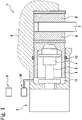
- Fig. 1 shows, according to the prior art, a schematic sectional view of a braking device 1 for a vehicle.
- the braking device 1 has an automated (automatic) parking brake (parking brake) which, by means of an actuator 2 (brake motor), can exert a clamping force to immobilize the vehicle.
- the actuator 2 of the parking brake drives a spindle 3, in particular a threaded spindle, which is mounted in an axial direction 3, at.
- the spindle 3 is provided with a spindle nut 4, which rests against the brake piston 5 when the automated parking brake is applied.
- the parking brake electromechanically transmits a force to the brake linings 8, 8 'or the brake disc 7.
- the spindle nut rests on an inner face of the brake piston 5 (also called the rear of the brake piston head or inner piston head).
- the spindle nut 4 is displaced in the axial direction with a rotary movement of the actuator 2 and a resulting rotary movement of the spindle 3.
- the spindle nut 4 and the brake piston 5 are mounted in a brake caliper 6, which engages over a brake disk 7 like pliers.
- a brake lining 8, 8 ' is arranged on both sides of the brake disc 7.
- the electric motor (actuator 2) rotates, whereupon the spindle nut 4 and the brake piston 5 are moved in the axial direction towards the brake disc 7, in order to create a predetermined clamping force between the brake linings 8, 8 'and the brake disc 7 to generate. Due to the spindle drive and the self-locking associated therewith, a force generated by the parking brake by means of a control of the electric motor is retained even when the control is terminated.
- the automated parking brake is, for example, designed as a "motor on caliper" system as shown and combined with the service brake. This could also be seen as being integrated into the service brake system. Both the automated parking brake and the service brake access the same brake piston 5 and the same brake caliper 6 in order to build up a braking force on the brake disk 7. However, the service brake has a separate actuator 10.
- the service brake is in Fig. 1 designed as a hydraulic system, wherein the actuator 10 can be represented by the ESP pump or a so-called iBooster. During service braking, a predetermined clamping force is built up hydraulically between the brake linings 8, 8 'and the brake disc 7.
- a medium 11 in particular an essentially incompressible brake fluid 11, is converted into a pressed by the brake piston 5 and the brake caliper 6 limited fluid space.
- the brake piston 5 is sealed off from the environment by means of a piston sealing ring 12.
- the brake actuators 2 and 10 are controlled by means of an output stage, i.e. by means of a control device 9, which can be, for example, a control device of a vehicle dynamics system such as ESP (electronic stability program) or some other control device.
- a control device 9 can be, for example, a control device of a vehicle dynamics system such as ESP (electronic stability program) or some other control device.
- the free travel or the clearance must first be overcome before a braking force can be built up.
- the distance which the spindle nut 4 has to overcome as a result of the rotation of the spindle 3 in order to come into contact with the brake piston 5 is referred to, for example, as the free travel.
- the clearance between the brake linings 8, 8 'and the brake disc 7 in the case of disc brake systems in motor vehicles is referred to as the clearance.
- This process usually takes a relatively long time with regard to the overall control, especially in the case of the automated parking brake.
- Fig. 1 shows the state of the free travel and clearance that have already been overcome.
- the brake linings 8, 8 ' are applied to the brake disc 7 and all brakes, ie the parking brake and the service brake, can immediately build up a braking force on the corresponding wheel upon subsequent activation.
- the descriptions of idle travel and clearance also apply in an analogous manner to the service brake, but because of the high pressure build-up dynamics, overcoming an idle travel is less time-consuming than with the parking brake.
- Fig. 2 shows a flow chart of a possible embodiment of the procedure according to the invention.
- S1 denotes the starting point of the procedure.
- the procedure is started, for example, when a parking brake request, for example a parking situation, is recognized.
- pressure provision is activated by means of the hydraulic service brake in step S2.
- a defined hydraulic pressure is generated and fed into the brake system. This is, for example, 40 bar. Due to the hydraulic pressure provided, the vehicle can initially be held hydraulically, even if only with less force.
- the pressure can be provided by means of electrified components of the hydraulic service brake system, for example by means of an electrified pressure booster, a so-called iBooster. If such components are used, the pressure can be provided relatively quickly, since no liquid (as, for example, with a classic ESP pump) has to be sucked in.
- the pressure is provided by means of an iBooster purely by shifting the fluid volume.
- the electromechanical actuator is activated. This must first overcome the existing idle travel in a known manner. As soon as the spindle nut hits the spindle base, however, there is a steep increase in force because the brake system is already pre-tensioned. From this point in time, the electrohydraulic and the electromechanical force work together. The superposition of the two force components results in a total force that generates a clamping force in the brake system. The built-up force or total clamping force is checked in a further step S4 to determine whether it corresponds to a defined, required force. If this is not the case (N), the force component generated by means of the electromechanical actuator is increased.
- the electromechanical actuator is switched off in a next step S5.
- the electrohydraulic actuator is also switched off in a step S6.
- the two steps S5 and S6 can also be carried out simultaneously, that is, the actuators can be switched off at the same time.
- the final step 7 indicates the end of the procedure.
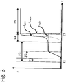
- Fig. 3 shows a schematic representation of the force curve F during and after an application process according to the invention. While Fig. 2 provides a procedural representation of the procedure, clarifies Fig. 3 same procedure over a temporal perspective t.
- the method starts at time t1. First of all, a defined hydraulic system is built up Pressure value. An actuator of the service brake system is activated for this. This is, for example, the iBooster. In phase P1, the idle travel and the clearance of the service brake are overcome. The electrohydraulic force component Fhydr is generated in a phase P2. A defined pressure value is generated for this. As soon as the pressure value has been generated, it only needs to be maintained in the further course.
- the actuator of the parking brake system is also activated at the same time as the activation of the actuator of the service brake system.
- the free travel of the parking brake is overcome in phase P3. After the free travel of the parking brake has been overcome, i.e. when the spindle nut is in contact with the brake piston, a steep increase in force occurs when the spindle nut is deflected further, since the brake system is already pre-tensioned by means of the hydraulic service brake.
- the actual superposition of the parking brake and the service brake takes place.
- the electromechanical force component Fmech is generated by activating the parking brake. This is superimposed on the existing electrohydraulic force component Fhydr and increases the total clamping force Ftot.
- the actuation of the parking brake actuator continues until the required total clamping force Ftot is reached.
- the displacement of the brake piston results in an increase in the fluid volume between the brake caliper and the brake piston.
- the hydraulic pressure may have to be adjusted by means of the service brake. This can be done in a targeted manner using an iBooster system, which is equipped with appropriate force sensors and means for pressure monitoring.
- the control is withdrawn, that is, the electromechanical and electrohydraulic actuators are switched off at time t2. This avoids a further build-up of force. By switching off the actuators, the electromechanical force component Fmech and the electrohydraulic force component Fhydr are also withdrawn.
- the total clamping force Ftot that has built up is maintained even after the application process has ended, since the exemplary parking brake, as described, is provided with a self-locking mechanism, as in phase P5 is shown. Only an active control of the parking brake in the opposite direction leads to a release of the parking brake, but this is not the case Fig. 3 is shown.
Description
Die vorliegende Erfindung bezieht sich auf eine Bremsvorrichtung für ein Kraftfahrzeug und ein Verfahren zur Ansteuerung der Bremsvorrichtung mittels einer Überlagerung verschiedener Kraftkomponenten, wobei die elektromechanischen Kraftkomponente frühestens zeitgleich mit der hydraulischen Kraftkomponente erzeugt wird.The present invention relates to a braking device for a motor vehicle and a method for controlling the braking device by superimposing various force components, the electromechanical force component being generated at the earliest at the same time as the hydraulic force component.
Bekannte automatisierte Feststellbremssysteme, sogenannte APB (automated parking brakes), sind so ausgelegt, dass sie die notwendige Feststellbremskraft in der Regel vollständig mittels eines Feststellbremsaktuators, beispielsweise mittels eines elektromechanischen Aktuators bereitstellen können. Nur in wenigen Ausnahmen, wenn z. B. der Feststellbremsaktuator sehr warm ist und/oder die Spannung gering ist, kann es dazu kommen, dass bspw. eine hydraulische Unterstützung des elektromechanischen Aktuators, (auch elektromechanischer Steller bezeichnet) notwendig wird. Bekannte Feststellbremssysteme können die notwendige Feststellbremskraft nur leisten weil sie auf ein entsprechendes Lastprofil der Aktuierung mittels eines einzigen Feststellbremsaktuators hin ausgelegt sind. Darüber hinaus muss auch der elektrische Pfad für die Feststellbremse eine entsprechende Leistung bereitstellen können.Known automated parking brake systems, so-called APB (automated parking brakes), are designed so that they can generally provide the necessary parking brake force completely by means of a parking brake actuator, for example by means of an electromechanical actuator. Only in a few exceptions, if z. If, for example, the parking brake actuator is very warm and / or the voltage is low, it can happen that, for example, hydraulic support of the electromechanical actuator (also referred to as electromechanical actuator) is necessary. Known parking brake systems can only provide the necessary parking brake force because they are designed for a corresponding load profile of the actuation by means of a single parking brake actuator. In addition, the electrical path for the parking brake must also be able to provide a corresponding power.
Aus dem Stand der Technik ist beispielsweise die
Weiterhin ist aus dem Stand der Technik beispielsweise die
Weiterhin ist aus dem Stand der Technik bspw. die
Weiterhin ist aus dem Stand der Technik bspw. die
Weiterhin ist aus dem Stand der Technik bspw. die
Weiterhin ist aus dem Stand der Technik bspw. die
Der Erfindung liegt die Aufgabe zu Grunde die bei einer Aktivierung der Feststellbremse benötigte Applikationszeit der Wirkung der Feststellbremse zu verkürzen und dabei eine Auslegung der Komponenten der Feststellbremse zu optimierten.The invention is based on the object of shortening the application time of the effect of the parking brake, which is required when the parking brake is activated, and at the same time optimizing the design of the components of the parking brake.
Diese Aufgabe wird durch die Merkmale der unabhängigen Patentansprüche gelöst. Weiterbildungen der Erfindung sind in den abhängigen Patentansprüchen angegeben.This object is achieved by the features of the independent patent claims. Further developments of the invention are specified in the dependent claims.
Hierfür ist ein Verfahren zur Durchführung eines Feststellbremsvorgangs bei einem Kraftfahrzeug mit einer Betriebsbremse und einer Feststellbremse vorgesehen, wobei eine hydraulische Kraftkomponente und eine elektromechanische Kraftkomponente zur Erzielung einer Gesamtklemmkraft für den Feststellbremsvorgang überlagert werden. Erfindungsgemäß ist vorgesehen, dass die Überlagerung der beiden Kraftkomponenten bei jedem Feststellbremsvorgang erfolgt, wobei die elektromechanischen Kraftkomponente frühestens zeitgleich mit der hydraulischen Kraftkomponente erzeugt wird.For this purpose, a method is provided for carrying out a parking brake process in a motor vehicle with a service brake and a parking brake, a hydraulic force component and an electromechanical force component being superimposed to achieve a total clamping force for the parking brake process. According to the invention, it is provided that the two force components are superimposed during each parking brake operation, the electromechanical force component being generated at the earliest at the same time as the hydraulic force component.
Unter einem Feststellbremsvorgang ist jeder Vorgang zu verstehen, welcher ein Fahrzeug feststellt. Insbesondere ist hierbei ein Parkvorgang eines Fahrzeugs zu verstehen, bei welchem der Fahrer das Fahrzeug verlässt. Weiterhin kann sich ein Feststellbremsvorgang auch auf Vorgänge beziehen, welche ein kurzzeitiges Halten eines Fahrzeugs, bspw. bei einem Haltevorgang am Berg, ermöglichen.A parking brake process is to be understood as any process which locks a vehicle. In particular, a parking process of a vehicle is to be understood here in which the driver leaves the vehicle. Furthermore, a parking brake process can also relate to processes which enable a vehicle to be stopped briefly, for example during a stop process on a hill.
Eine Überlagerung erfolgt erfindungsgemäß selbstverständlich bereits bei einem initialen Feststellbremsvorgang ohne anschließenden Nachspannvorgang. Weiterhin ist es nicht notwendig ist, dass weitere Bedingungen erfüllt sind, aus welchen bspw. abgeleitet wird, dass eine einzelne Kraftkomponente nicht ausreichend ist und daher eine weitere Kraftkomponente notwendig ist. Die Überlagerung der Kraftkomponenten wird durch einen Superpositionsbetrieb der Betriebsbremse und der Feststellbremse erzielt. Die beiden Bremsen werden erfindungsgemäß bei jedem Feststellbremsvorgang im Superpositionsbetrieb betrieben. Das heißt, beide Bremsen arbeiten in der Art zusammen, dass die durch sie erzeugten Kraftkomponenten sich gegenseitig ergänzen. Die Kraftkomponenten wirken auf den Bremskolben und darüber auf die Bremsbeläge, welche eine Klemmkraft zwischen den Bremsbelägen und der Bremsscheibe erzeugen. Die sich ergebende Gesamtklemmkraft kann daher als Summe der beiden Kraftkomponenten verstanden werden.According to the invention, a superimposition takes place, of course, already during an initial parking brake process without a subsequent re-tensioning process. Furthermore, it is not necessary that further conditions are met, from which it can be deduced, for example, that an individual force component is not sufficient and therefore a further force component is necessary. The superposition of the force components is achieved by superposing the service brake and the parking brake. According to the invention, the two brakes are operated in superposition mode during each parking brake operation. This means that both brakes work together in such a way that the force components they generate complement each other. The force components act on the brake piston and via it on the brake linings, which generate a clamping force between the brake linings and the brake disc. The resulting total clamping force can therefore be understood as the sum of the two force components.
Durch das erfindungsgemäße Verfahren wird insbesondere die Applikationszeit hinsichtlich der Feststellbremswirkung reduziert. Hierunter ist zu verstehen, dass die Feststellbremswirkung innerhalb einer kürzeren Zeit als nur bei der Aktivierung eines Bremssystems bereit gestellt werden kann. Weiterhin können aufgrund der permanenten, d.h. bei jedem Feststellbremsvorgang vorliegenden, Überlagerung der beiden Bremssysteme die beiden Bremssysteme, insbesondere das Feststellbremssystem, entsprechend optimiert ausgelegt werden. Hierdurch reduzieren sich bspw. auch die Dimensionen und das benötigte Bauvolumen. Geringere Dimensionen haben einen positiven Einfluss auf das Gewicht des Systems. Weiterhin können durch eine optimierte Auslegung auch die Kosten des Feststellbremssystems reduziert werden.The method according to the invention, in particular, reduces the application time with regard to the parking brake effect. This is to be understood as meaning that the parking brake action can be provided within a shorter time than just when a brake system is activated. Furthermore, because of the permanent superimposition of the two brake systems, that is to say during each parking brake operation, the two brake systems, in particular the parking brake system, can be designed in an appropriately optimized manner. This also reduces, for example, the dimensions and the required construction volume. Smaller dimensions have a positive influence on the weight of the system. Furthermore, the costs of the parking brake system can also be reduced through an optimized design.
In einer vorteilhaften Weiterbildung zeichnet sich das Verfahren dadurch aus, dass eine elektromechanische Kraftkomponente mittels einer automatisierten Feststellbremse und eine elektrohydraulische Kraftkomponente mittels der hydraulischen Betriebsbremse erzeugt wird, wobei die Erzeugung und die Überlagerung der beiden Kraftkomponenten bei jedem Feststellbremsvorgang erfolgt.In an advantageous development, the method is characterized in that an electromechanical force component is generated by means of an automated parking brake and an electrohydraulic force component is generated by means of the hydraulic service brake, the two force components being generated and superimposed during each parking brake operation.
Hierunter ist zu verstehen, dass die bei einem regulären Feststellbremsvorgang benötigte oder geforderte Gesamtklemmkraft in allen Anwendungsfällen durch ein Zusammenwirken der hydraulischen Betriebsbremse und der automatisierten Feststellbremse erzeugt wird. Die hydraulische Betriebsbremse und automatisierte Feststellbremse werden dafür in dem bereits beschriebenen Superpositionsbetrieb betrieben. Die erzeugten Kräfte werden dabei als Kraftkomponenten einer Gesamtkraft angesehen und dienen der Erzeugung der gewünschten Gesamtklemmkraft.This is to be understood as meaning that the total clamping force required or required for a regular parking brake operation is generated in all applications by the interaction of the hydraulic service brake and the automated parking brake. The hydraulic service brake and automated parking brake are operated for this in the superposition mode already described. The forces generated are viewed as force components of an overall force and are used to generate the desired overall clamping force.
Als elektrohydraulische Kraftkomponente ist insbesondere eine Kraftkomponente zu verstehen, welche von elektrifizierten Komponenten der Betriebsbremse, erzeugt wird. Als elektromechanische Kraftkomponente ist insbesondere eine Kraftkomponente zu verstehen, welche von einem elektrischen Aktuator (insbesondere Elektromotor) der automatisierten Feststellbremse erzeugt wird. Eine Überlagerung der Kraftkomponenten ist daher so zu verstehen, dass für die Erzeugung der Feststellbremskraft neben der Betätigung der Feststellbremsanlage auch eine Betätigung der Betriebsbremsanlage erfolgt. Das erfindungsgemäße Feststellbremssystem nutzt die somit erzeugte Kraftkomponente bedarfsgerecht für einen Aufbau einer Feststellbremskraft.An electrohydraulic force component is to be understood in particular as a force component that is generated by electrified components of the service brake. An electromechanical force component is to be understood in particular as a force component which is generated by an electric actuator (in particular an electric motor) of the automated parking brake. A superposition of the force components is therefore to be understood in such a way that, for the generation of the parking brake force, in addition to the actuation of the parking brake system, the service brake system is also actuated. The parking brake system according to the invention uses the force component thus generated as required to build up a parking brake force.
Zunehmend werden Teile der Betriebsbremsanlage elektrifiziert. So z.B. auch die Bremskraftverstärkung (iBooster) oder Systeme mit elektrifizierten Bremskraftverstärkern und elektrische Druckregelsysteme (lBox). Dies ist eine Komponente, die anstatt des Bremskraftverstärkers in das Fahrzeug eingebaut wird. Sie hat die Eigenschaft, dass sie sowohl die Bremskraft verstärken kann (wie aus dem Stand der Technik bekannten Bremskraftverstärker), als auch eine Bremskraft bereitstellen kann, ohne dass der Fahrer das Bremspedal betätigen muss. Der iBooster übernimmt dabei den kompletten Bremsdruckaufbau in dem er elektromechanisch den Bremszylinder entsprechend verschiebt. Mittels der Komponenten der elektrifizierten Betriebsbremse wird ein Bremsdruck unmittelbar in der Fahrzeugbremse bereitgestellt. Beispielsweise kann der iBooster einer elektrifizierten Bremsanlage nun in die Bereitstellung der Feststellbremsfunktion fest integriert werden. Selbstverständlich kann der elektrohydraulische Druckaufbau, d.h. die Erzeugung der elektrohydraulischen Kraftkomponente, auch mittels eines üblichen Aktuators eines ESP-Systems (Elektronisches Stabilitätsprogramm) erfolgen, d.h. mittels einer ESP-Pumpe.Parts of the service brake system are increasingly being electrified. For example brake booster (iBooster) or systems with electrified brake boosters and electrical pressure control systems (lBox). This is a component that is built into the vehicle instead of the brake booster. It has the property that it can both increase the braking force (as known from the prior art brake booster) and provide braking force without the driver having to press the brake pedal. The iBooster takes over the entire brake pressure build-up by electromechanically moving the brake cylinder accordingly. Brake pressure is provided directly in the vehicle brake by means of the components of the electrified service brake. For example, the iBooster of an electrified brake system can now be permanently integrated into the provision of the parking brake function. Of course he can electrohydraulic pressure build-up, ie the generation of the electrohydraulic force component, also take place by means of a conventional actuator of an ESP system (electronic stability program), that is to say by means of an ESP pump.
Durch das Verfahren der Überlagerung der elektromechanischen und der elektrohydraulischen Kraftkomponente bei jedem Feststellbremsvorgang ergibt sich nicht nur, wie bereits beschrieben, eine Reduktion der Applikationszeit hinsichtlich der Feststellbremswirkung. Im Vergleich zu bestehenden Feststellbremssystemen kann auch eine Optimierung der Auslegung von Komponenten (Motor, Getriebe) der Feststellbremse (kleiner, leichter und damit auch kostengünstiger) erfolgen. Hierdurch ergibt sich wiederum eine Reduktion der ungefederten Masse am Fahrzeug-Rad. Ebenfalls dient das Konzept einer Verringerung der Einschränkungen in Bezug auf die räumliche Anordnung der elektromechanischen Aktuators am Bremssattel. Hierdurch kann mehr Spielraum in der Gestaltung der Achsaufhängung und des Feder-Dämpfer-Systems erlangt werden. Des Weiteren kann durch die Optimierung der Auslegung der Komponenten auch eine Optimierung der Zuleitungen der Feststellbremse ermöglicht werden. Da eine erfindungsgemäße Feststellbremse weniger Abgabemoment bereitstellen muss, können bspw. auch die Zuleitungen günstiger ausgeführt werden. Die notwendige Leistungsübertragung über die Kabel ist im Vergleich zu bekannten Systemen reduziert. Hierdurch ergibt sich beispielsweise eine Reduzierung des Drahtdurchmessers zwischen Steuergerät und APB-Aktuatoren. Ebenfalls wird ein einfacheres Verlegen der Leitungen ermöglicht, bzw. eine freiere Wahl bzgl. der Kabelführung/Kabelaufhängung. Als weiterer Vorteil ergibt sich eine Vereinfachung der Endstufe im Steuergerät, da die elektrische Leistung, die über die H-Brücke geschalten werden muss, reduziert ist. Hierdurch können bspw. kleinere elektronische Komponenten eingesetzt werden.The method of superimposing the electromechanical and electrohydraulic force components in each parking brake operation not only results in a reduction in the application time with regard to the parking brake effect, as already described. Compared to existing parking brake systems, the design of components (motor, gearbox) of the parking brake (smaller, lighter and therefore also more cost-effective) can also be optimized. This in turn results in a reduction in the unsprung mass on the vehicle wheel. The concept also serves to reduce the restrictions with regard to the spatial arrangement of the electromechanical actuator on the brake caliper. This allows more leeway in the design of the axle suspension and the spring-damper system. Furthermore, by optimizing the design of the components, it is also possible to optimize the supply lines of the parking brake. Since a parking brake according to the invention has to provide less output torque, the supply lines, for example, can also be designed more cheaply. The necessary power transmission via the cables is reduced compared to known systems. This results in, for example, a reduction in the wire diameter between the control unit and APB actuators. Easier laying of the lines is also made possible, or a more free choice with regard to the cable routing / cable suspension. Another advantage is the simplification of the output stage in the control unit, since the electrical power that has to be switched via the H-bridge is reduced. In this way, for example, smaller electronic components can be used.
In vorteilhafter Weise zeichnet sich das Verfahren dadurch aus, dass der Feststellbremsvorgang wenigstens eine Kraftaufbauphase enthält, wobei im Wesentlichen während der gesamten Kraftaufbauphase die Überlagerung der Kraftkomponente erfolgt.The method is advantageously characterized in that the parking brake operation contains at least one force build-up phase, the force component being superimposed essentially during the entire force build-up phase.
Hierunter ist zu verstehen, dass der Feststellbremsvorgang mehrere Phasen umfassen kann. Die Kraftaufbauphase wird als die Phase angesehen in welcher die geforderte Klemmkraft aufgebaut wird. Vorteilhaft ist vorgesehen, dass während der gesamten Phase beide Aktuatoren der Bremssysteme eine Kraftkomponente liefern. Durch die Überlagerung mehrere Kraftkomponenten kann vorteilhaft die zu erzeugende Kraft auf beide Komponenten aufgeteilt werden. Eine Überlagerung während der gesamten Kraftaufbauphase ist dabei so zu verstehen, dass die Überlagerung während der gesamten zeitlichen Dauer des Kraftaufbaus im Superpositionsbetrieb erfolgt. Hierdurch kann ein möglichst schneller Aufbau der Gesamtklemmkraft erzielt werden. Weiterhin kann durch eine kontinuierliche Überlagerung eine Ermittlung einer Erreichung der erforderlichen Klemmkraft unterstützt werden.This is to be understood as meaning that the parking brake process can comprise several phases. The force build-up phase is seen as the phase in which the required clamping force is built up. It is advantageously provided that both actuators of the brake systems supply a force component during the entire phase. By superimposing several force components, the force to be generated can advantageously be divided between the two components. A superposition during the entire force build-up phase is to be understood in such a way that the superposition takes place during the entire time duration of the force build-up in superposition mode. As a result, the overall clamping force can be built up as quickly as possible. Furthermore, a continuous superimposition can help determine whether the required clamping force has been reached.
In einer vorteilhaften Ausgestaltung zeichnet sich das Verfahren dadurch aus, dass bei einer Aktivierung des Feststellbremsvorgangs in einem ersten Schritt die elektrohydraulische Kraftkomponente erzeugt wird.In an advantageous embodiment, the method is characterized in that when the parking brake process is activated, the electrohydraulic force component is generated in a first step.
Unter Erzeugung ist dabei die tatsächliche Erzeugung einer Kraftkomponente, bspw. mittels eines aufgebauten Drucks durch die elektrifizierten Komponenten der hydraulischen Betriebsbremsanlage zu verstehen. Eine Aktivierung des Feststellbremsvorgangs kann erfolgen, sobald eine Feststellbremsanforderung erkannt wird. Eine Feststellbremsanforderung kann bspw. vom Fahrer mittels einer manuellen Betätigung eines Tasters erfolgen. Ebenfalls sind automatisierte Anforderungen der Feststellbremskraft Stand der Technik, bspw. bei einem Halten am Berg. Selbstverständlich kann bei (bzw. nach) einer derartigen Aktivierung des Feststellbremsvorgangs eine Aktivierung der Bremsaktuatoren erfolgen. Hierbei ist vorgesehen den Aktuator der Betriebsbremse anzusteuern um die elektrohydraulische Kraftkomponente zu erzeugen. Dieser Aktuator besitzt eine hohe Dynamik im Druckaufbau und kann dadurch in kurzer Zeit eine erste Kraftkomponente bereitstellen. Diese Kraftkomponente kann bereits nach kurzer Zeit eine erste Klemmkraft für den Feststellbremsvorgang bereitstellen. Dies gilt auch bei Tieftemperaturen, insbesondere wenn zur Druckerzeugung keine Hydraulikflüssigkeit angesaugt werden muss (wie bspw. beim ESP), sondern statt dessen bspw. mittels eines iBoosters der Bremszylinder und damit direkt ein Fluidvolumen verschoben wird.Generation is to be understood as the actual generation of a force component, for example by means of a pressure built up by the electrified components of the hydraulic service brake system. The parking brake process can be activated as soon as a parking brake request is recognized. A parking brake request can be made, for example, by the driver by manually actuating a button. Automated requirements for the parking brake force are also state of the art, for example when stopping on a hill. Of course, the brake actuators can be activated during (or after) such an activation of the parking brake process. It is intended to control the actuator of the service brake in order to generate the electrohydraulic force component. This actuator has a high dynamic in pressure build-up and can therefore provide a first force component in a short time. This force component can already provide a first clamping force for the parking brake process after a short time. This also applies at low temperatures, especially when generating pressure no hydraulic fluid has to be sucked in (as is the case with ESP, for example), but instead, for example, the brake cylinder and thus a volume of fluid is shifted by means of an iBooster.
In einer vorteilhaften Weiterbildung zeichnet sich das Verfahren dadurch aus, dass bei dem Feststellbremsvorgangs ein definierter hydraulischer Druck erzeugt wird.In an advantageous development, the method is characterized in that a defined hydraulic pressure is generated during the parking brake process.
Ein definierter hydraulischer Druck ist dabei als ein festgelegter Druckwert zu verstehen. Dieser beträgt beispielsweise 40 bar. Die Höhe des Druckwerts korreliert mit einer entstehenden hydraulischen Kraftkomponente. Die Festlegung des Druckwerts ist von der Bremssystemauslegung sowie einer Definition des Feststellbremsvorgangs abhängig. Weiterhin kann vorteilhaft vorgesehen sein, dass für alle Feststellbremssituationen ein gleicher Druckwert gewählt wird, d.h. der Druckwert unabhängig von dem Fahrzeugzustand oder den Umgebungsbedingungen ist, um den Regelungsaufwand gering zu halten. In einer alternativen Ausführung ist vorgesehen die Höhe des Druckwert in Abhängigkeit des Fahrzeugzustandes oder der Umgebungsbedingungen einzustellen um ggf. in spezifischen Situationen eine maximale Druckunterstützung zu ermöglichen, während in anderen Situation eine geringere Druckunterstützung bereitgestellt wird, um bspw. die Komponentenbelastung zu reduzieren. Der definierte hydraulische Druck kann bspw. mittels elektrifizierter Komponenten der hydraulischen Betriebsbremsanlage erzeugt werden. Vorteilhafterweise ist der erzeugte hydraulische Druck des Weiteren unabhängig von einer möglichen Bremspedalbetätigung. Hierunter soll verstanden werden, dass ein mittels einer Bremspedalbetätigung erzeugtes Druckniveau entsprechend berücksichtigt wird und der mittels der elektrifizierten Komponenten erzeugte Druck entsprechend angepasst wird, so dass die sich ergebende hydraulische Kraftkomponente den festgelegten Wert erreicht.A defined hydraulic pressure is to be understood as a fixed pressure value. This is 40 bar, for example. The level of the pressure value correlates with a resulting hydraulic force component. The determination of the pressure value depends on the brake system design and a definition of the parking brake process. Furthermore, it can advantageously be provided that the same pressure value is selected for all parking brake situations, i.e. the pressure value is independent of the vehicle condition or the ambient conditions, in order to keep the control effort low. In an alternative embodiment, provision is made to set the level of the pressure value depending on the vehicle condition or the ambient conditions in order to enable maximum pressure support in specific situations, while lower pressure support is provided in other situations, for example to reduce the component load. The defined hydraulic pressure can be generated, for example, by means of electrified components of the hydraulic service brake system. Furthermore, the hydraulic pressure generated is advantageously independent of a possible brake pedal actuation. This should be understood to mean that a pressure level generated by means of a brake pedal actuation is taken into account accordingly and the pressure generated by means of the electrified components is adapted accordingly, so that the resulting hydraulic force component reaches the specified value.
In einer weiteren vorteilhaften Ausgestaltung zeichnet sich das Verfahren dadurch aus, dass in einem zweiten Schritt die elektromechanische Kraftkomponente erzeugt wird, wobei insbesondere der zweite Schritt nach oder zeitgleich mit dem ersten Schritt ausgeführt wird.In a further advantageous embodiment, the method is characterized in that, in a second step, the electromechanical Force component is generated, in particular the second step is carried out after or at the same time as the first step.
Hierdurch wird verdeutlicht, dass die Kraftkomponenten nicht gleichzeitig erzeugt werden müssen. Insbesondere soll dies so verstanden werden, dass die elektromechanische Kraftkomponente frühestens zeitgleich mit der hydraulischen Kraftkomponente erzeugt wird. Aufgrund der unterschiedlichen Dynamiken haben beide Systeme unterschiedliche Aktivierungszeiten bis zum Aufbau, d. h. der tatsächlichen Erzeugung, einer Bremskraft. Hierbei weist die hydraulische Betriebsbremse in der Regel eine höhere Dynamik auf als die elektromechanische Feststellbremse. Aufgrund der Dynamik der Systeme ist bspw. bei einer zeitgleichen Aktivierung der Aktuatoren beider Systeme davon auszugehen, dass die Erzeugung der elektrohydraulischen Kraftkomponente vor der Erzeugung der elektromechanischen Kraftkomponente erfolgt. Da in diesem Fall die elektrohydraulische Kraftkomponente zu einem früheren Zeitpunkt zur Verfügung steht, wird bereits eine erste Klemmkraft erzeugt, wenn auch diese gegenüber der geforderten Gesamtklemmkraft reduziert und nicht für den Feststellbremsvorgang ausreichend ist. Es ist dabei im Rahmen des Vorgehens vorgesehen, diesen Effekt zu nutzen und vorteilhaft eine erste Kraftkomponente für eine Klemmkraft aufzubauen, wenn auch die erforderliche zweite Kraftkomponente bestenfalls zeitgleich aller Wahrscheinlichkeit nach aber erst zu einem späteren Zeitpunkt erzeugt werden kann. Mittels einer zeitlich versetzten Erzeugung der Kraftkomponente kann darüber hinaus ein stufenförmiger Kraftaufbau ermöglicht werden. Hierdurch kann die Komponentenbelastung reduziert werden.This makes it clear that the force components do not have to be generated at the same time. In particular, this should be understood to mean that the electromechanical force component is generated at the earliest at the same time as the hydraulic force component. Due to the different dynamics, the two systems have different activation times until they are set up, i. H. the actual generation, a braking force. Here, the hydraulic service brake generally has a higher dynamic than the electromechanical parking brake. Due to the dynamics of the systems, for example, when the actuators of both systems are activated at the same time, it can be assumed that the electrohydraulic force component is generated before the electromechanical force component is generated. Since in this case the electrohydraulic force component is available at an earlier point in time, a first clamping force is already generated if this too is reduced compared to the required total clamping force and is not sufficient for the parking brake operation. It is provided within the scope of the procedure to use this effect and advantageously to build up a first force component for a clamping force, even if the required second force component can at best be generated at the same time in all probability, but only at a later point in time. In addition, a step-like build-up of force can be made possible by means of a time-staggered generation of the force component. This can reduce the component load.
In einer vorteilhaften alternativen Ausgestaltung des Verfahrens ist vorgesehen, dass bei einer Aktivierung des Feststellbremsvorgangs in einem ersten Schritt die hydraulische Betriebsbremse aktiviert wird und in einem zweiten Schritt die automatisierte Feststellbremse aktiviert wird, wobei insbesondere der zweite Schritt nach oder zeitgleich mit dem ersten Schritt ausgeführt wird.In an advantageous alternative embodiment of the method, it is provided that when the parking brake process is activated, the hydraulic service brake is activated in a first step and the automated parking brake is activated in a second step, the second step in particular being carried out after or at the same time as the first step .
Hierunter ist zu verstehen, dass die Aktivierung der Betriebsbremse vor dem Zeitpunkt der Aktivierung der Feststellbremse erfolgt. Um die Applikationszeit der Feststellbremswirkung zu verkürzen ist vorgesehen, zunächst die Applikation der Feststellbremskraft über hydraulische Mittel zu starten und den hydraulischen Anteil anschließend mit dem elektromechanischen Anteil zu überlagern. Mittels einer zeitlich versetzten Aktivierung der Feststellbremse nach der Aktivierung der Betriebsbremse kann weiterhin ein stufenförmiger Kraftaufbau unterstützt werden. Hierdurch kann die Komponentenbelastung weiter reduziert werden.This means that the service brake is activated before the parking brake is activated. In order to shorten the application time of the parking brake effect, provision is made first to start the application of the parking brake force via hydraulic means and then to superimpose the hydraulic component with the electromechanical component. By means of a time-delayed activation of the parking brake after the activation of the service brake, a gradual build-up of force can also be supported. In this way, the component load can be further reduced.
In einer vorteilhaften Weiterbildung ist das Verfahren dadurch gekennzeichnet, dass eine Erhöhung der elektromechanischen Kraftkomponente ausgeführt wird bis eine Gesamtklemmkraft erreicht ist.In an advantageous development, the method is characterized in that the electromechanical force component is increased until a total clamping force is reached.
Hierunter soll verstanden werden, dass in einem ersten Schritt die hydraulische Kraftkomponente erzeugt wird, welche im weiteren Verlauf konstant gehalten wird. Dieser Kraftkomponente wird in einem zweiten Schritt, bspw. im Rahmen einer sogenannten Kraftaufbauphase, eine elektromechanische Kraftkomponente überlagert. Diese elektromechanische Kraftkomponente ist variabel und wird im Verlauf der Kraftaufbauphase erhöht. Die Kraftkomponente wird solange erhöht, bis eine definierte, bzw. geforderte Gesamtklemmkraft erreicht ist. Das heißt der zweite Schritt wird ausgeführt, bis die elektromechanische Kraftkomponente eine Differenz zwischen einer definierten Gesamtklemmkraft und der eingestellten hydraulischen Kraftkomponente abgebaut hat. Dadurch, dass im Verlauf der Kraftaufbauphase eine Kraft (elektrohydraulische Kraftkomponente) konstant gehalten wird, während nur eine weitere Kraft (elektromechanische Kraftkomponente) verändert wird, kann vorteilhafterweise der regelungstechnische Aufwand gering gehalten werden, da nur eine Größe nachzuführen ist.This should be understood to mean that the hydraulic force component is generated in a first step, which is kept constant in the further course. In a second step, for example in the context of a so-called force build-up phase, an electromechanical force component is superimposed on this force component. This electromechanical force component is variable and is increased in the course of the force build-up phase. The force component is increased until a defined or required total clamping force is reached. This means that the second step is carried out until the electromechanical force component has reduced a difference between a defined total clamping force and the set hydraulic force component. Because one force (electrohydraulic force component) is kept constant in the course of the force build-up phase, while only one other force (electromechanical force component) is changed, the control effort can advantageously be kept low, since only one variable needs to be tracked.
In einer vorteilhaften Weiterbildung ist vorgesehen, dass eine Ansteuerung von Mitteln zur Erzielung der elektrohydraulischen Kraftkomponente nach Erreichen der Gesamtklemmkraft zurückgenommen wird.In an advantageous further development, it is provided that activation of means for achieving the electrohydraulic force component is withdrawn after the total clamping force has been reached.
Hierunter ist zu verstehen, dass nach einem Erreichen der erforderlichen Gesamtklemmkraft mittels einer Überlagerung der beiden Bremssysteme, die Mittel zur Erzielung der elektrohydraulischen Kraftkomponente zurückgenommen werden. Hierzu zählen bspw. die Ansteuerung des Aktuators, des iBooster, als auch von hydraulischen Ventilen. Je nach vorliegender Fahrsituation können die Mittel auch direkt im Anschluss für eine anstehende Aufgabe entsprechend der vorliegenden Fahrsituation vorbereitet werden. Die Zurücknahme kann erfolgen, sobald das Erreichen der Gesamtklemmkraft erkannt worden ist. Hierdurch kann ein weiterer Kraftanstieg vermieden werden.This means that after the required total clamping force has been reached by superimposing the two brake systems, the means for achieving the electrohydraulic force component are withdrawn. This includes, for example, the control of the actuator, the iBooster and hydraulic valves. Depending on the prevailing driving situation, the means can also be prepared directly afterwards for an upcoming task in accordance with the prevailing driving situation. The withdrawal can take place as soon as the total clamping force has been reached. In this way, a further increase in force can be avoided.
In einer vorteilhaften Weiterbildung ist vorgesehen, dass nach Erreichen der Gesamtklemmkraft eine Ansteuerung von Mitteln zur Erzielung der elektromechanischen Klemmkraft sowie eine Ansteuerung von Mitteln zur Erzielung der elektrohydraulischen Kraftkomponente im Wesentlichen zeitgleich zurückgenommen werden.In an advantageous development, it is provided that after the total clamping force has been reached, activation of means for achieving the electromechanical clamping force and activation of means for achieving the electrohydraulic force component are essentially withdrawn at the same time.
Hierunter ist zu verstehen, dass eine Zurücknahme der Ansteuerung, bspw. der Aktuatoren zum selben Zeitpunkt erfolgt. Hierdurch kann vermieden werden, dass eine Überbelastung eines einzelnen Aktuators nach einem Wegfall einer Kraftkomponente auftritt.This means that the activation, for example the actuators, is withdrawn at the same point in time. In this way, it can be avoided that an individual actuator is overloaded after a force component has ceased to exist.
Weiterhin ist erfindungsgemäß ein Steuergerät zur Durchführung eines Feststellbremsvorgangs bei einem Kraftfahrzeug mit einer Betriebsbremse und einer Feststellbremse vorgesehen, welches ausgestaltet ist und Mittel aufweist, ein Verfahren nach einem der vorgenannten Ansprüchen durchzuführen.Furthermore, according to the invention, a control device is provided for carrying out a parking brake operation in a motor vehicle with a service brake and a parking brake, which is designed and has means to carry out a method according to one of the preceding claims.
Hierunter ist zu verstehen, dass das Steuergerät ausgebildet, das heißt eingerichtet, ist und Mittel aufweist das beschriebene Verfahren durchzuführen.This is to be understood as meaning that the control device is designed, that is to say set up, and has means to carry out the described method.
Weiterhin ist erfindungsgemäß eine automatisierte Feststellbremse für ein Kraftfahrzeug mit einer hydraulischen Betriebsbremse vorgesehen, wobei die Feststellbremse ausgestaltet ist und Mittel aufweist, ein Verfahren nach einem der vorgenannten Ansprüchen durchzuführen. In einer vorteilhaften Ausgestaltung ist vorgesehen, dass die Feststellbremse als "Motor on Caliper"-Konzept ausgeführt ist.Furthermore, an automated parking brake for a motor vehicle with a hydraulic service brake is provided according to the invention, the Parking brake is designed and has means to carry out a method according to one of the preceding claims. In an advantageous embodiment it is provided that the parking brake is designed as a "motor on caliper" concept.
Dabei erfolgt die Auslegung der Feststellbremse bewusst in der Art, dass der elektromechanische Anteil bezüglich ihrer bereitstellbaren Klemmkraft zwischen 40 und 60% der Gesamtklemmkraft bekannten elektromechanischen Systemen darstellt. D.h. bekannte Systeme sind in der Regel so ausgelegt, dass diese unter nominellen (12V, Raumtemperatur) Bedingungen die Klemmkraft bereitstellen können (ungefährer Kraftwert ca. 18 kN), die ausreichend ist das Fahrzeug bis an 30% Steigung abzustellen. Üblicherweise sind bei bekannten Feststellbremssystemen für Steigungen von bis zu 20% (gesetzliche Forderung) geringere Klemmkräfte ausreichend (ungefährer Kraftwert ca. 8,5 kN bis 10 kN). Durch die Reduktion der notwendigen bereitzustellenden elektromechanischen Klemmkraft können der elektromechanische als auch der elektrische Teil der Feststellbremsanlage kleiner, leichter und damit auch kostengünstiger ausgeführt werden. Eine vorteilhafte Ausgestaltung der Feststellbremse sieht daher eine Auslegung auf eine Kraft von etwa 8,5 kN bis 10 kN vor. Durch eine derartige Auslegung können Systeme definiert werden, die bereits eine erhebliche Kostenreduktion im Vergleich mit bekannten Systemen darstellen. Das Verriegeln selbst (das Halten der Verriegelungskraft) ist unverändert, da sich der Bremskolben auch weiterhin auf dem Mutter-Spindel-System abstützt. Um sowohl mögliche Toleranzen der Kraftbereitstellung (einschließlich Varianz der Reibwertes der Bremsbeläge) als auch (thermische) Setzeffekte hinreichend zu berücksichtigen wird ca. 3 kN bis 4 kN stärker zugespannt, als rechnerisch bzw. physikalisch notwendig wäre. Da der elektromechanische Steller, wie oben beschrieben, aufgrund der Auslegung nicht ausreichend ist, die Klemmkraft von z.B. 13 kN alleine bereitzustellen wird bei jeder Aktuierung (Feststellbremskraftaufbau) der elektromechanische Steller hydraulisch unterstützt. D.h. die Klemmkraftbereitstellung erfolgt generell im Sinne einer Superposition aus elektromechanischer und elektrohydraulischer Klemmkraft.The parking brake is deliberately designed in such a way that the electromechanical component, with regard to the clamping force that can be provided, represents between 40 and 60% of the total clamping force of known electromechanical systems. Known systems are usually designed so that they can provide the clamping force under nominal (12V, room temperature) conditions (approximate force value approx. 18 kN), which is sufficient to park the vehicle up to a 30% gradient. With known parking brake systems, lower clamping forces are usually sufficient for gradients of up to 20% (legal requirement) (approximate force value approx. 8.5 kN to 10 kN). By reducing the electromechanical clamping force that is required to be provided, the electromechanical and also the electrical part of the parking brake system can be made smaller, lighter and thus also more cost-effective. An advantageous embodiment of the parking brake therefore provides for a force of approximately 8.5 kN to 10 kN. Such a design allows systems to be defined which already represent a considerable cost reduction in comparison with known systems. The locking itself (holding the locking force) is unchanged, as the brake piston continues to be supported on the nut-spindle system. In order to adequately take into account both possible tolerances in the provision of force (including variance in the coefficient of friction of the brake linings) and (thermal) setting effects, approx. 3 kN to 4 kN more than would be mathematically or physically necessary. Since the electromechanical actuator, as described above, is not sufficient due to its design to provide the clamping force of, for example, 13 kN on its own, the electromechanical actuator is hydraulically supported with every actuation (parking brake force build-up). This means that the clamping force is generally provided in the sense of a superposition of electromechanical and electrohydraulic clamping force.
In einer alternativen vorteilhaften Auslegung der Feststellbremse ist vorgesehen, dass der elektromechanische Anteil zwischen 20 und 40% der bereitstellbaren Klemmkraft darstellt. Die restliche Klemmkraft wird insbesondere durch den im Fahrzeug vorhandene hydraulischen Aktuator bereitgestellt. Durch eine derartige Auslegung können Systeme definiert werden, die ledigliche eine minimale Dimensionierung des elektromechanischen Stellers vorsehen. Hierdurch kann - bei Verwendung der bereits vorhandenen hydraulischen Druckbereitsstellungeine weitere Kostenreduktion ermöglicht werden. Der elektromechanische Steller ist hierbei so ausgelegt, dass er das Fahrzeug gemäß gesetzlichen Forderungen verzögert. Die Verzögerung erfolgt jedoch in der Regel mittels hydraulischer Druckbereitstellung. Nur im Falle einer nicht verfügbaren oder nicht ausreichend verfügbaren Druckbereitstellung kann der elektromechanische Steller die Druckbereitstellung übernehmen.In an alternative advantageous design of the parking brake, it is provided that the electromechanical component represents between 20 and 40% of the clamping force that can be provided. The remaining clamping force is provided in particular by the hydraulic actuator present in the vehicle. Such a design allows systems to be defined which only provide minimal dimensions for the electromechanical actuator. In this way, a further cost reduction can be made possible when using the already existing hydraulic pressure provision. The electromechanical actuator is designed in such a way that it decelerates the vehicle in accordance with legal requirements. However, the delay usually takes place by means of hydraulic pressure supply. The electromechanical actuator can only take over the provision of pressure in the event of an unavailable or insufficiently available print preparation.
Weitere Merkmale und Zweckmäßigkeit der Erfindung ergeben sich aus der Beschreibung von Ausführungsbeispielen anhand der beigefügten Figuren.
-
Fig. 1 als Stand der Technik eine schematische Schnittansicht einer Bremsvorrichtung mit einer automatischen Feststellbremse in "motor on caliper" Bauweise; -
Fig. 2 ein Ablaufdiagramm des erfindungsgemäßen Vorgehens; und -
Fig. 3 eine schematische Darstellung des Kräfteverlaufs während und nach der Zuspannphase eines erfindungsgemäßen Feststellbremsprozesses.
-
Fig. 1 as prior art, a schematic sectional view of a braking device with an automatic parking brake in "motor on caliper"construction; -
Fig. 2 a flow chart of the procedure according to the invention; and -
Fig. 3 a schematic representation of the force curve during and after the application phase of a parking brake process according to the invention.
Zu beiden Seiten der Bremsscheibe 7 ist jeweils ein Bremsbelag 8, 8' angeordnet. Im Fall eines Zuspannvorgangs der Bremsvorrichtung 1 mittels der automatisierten Feststellbremse dreht sich der Elektromotor (Aktuator 2), woraufhin die Spindelmutter 4 sowie der Bremskolben 5 in der axialen Richtung auf die Bremsscheibe 7 zubewegt werden, um so eine vorbestimmte Klemmkraft zwischen den Bremsbelägen 8, 8' und der Bremsscheibe 7 zu erzeugen. Aufgrund des Spindelantriebs und der damit verbundenen Selbsthemmung wird eine bei der Feststellbremse mittels einer Ansteuerung des Elektromotors erzeugte Kraft auch bei einer Beendigung der Ansteuerung weiter gehalten.A
Die automatisierte Feststellbremse ist bspw. wie abgebildet als "motor on caliper" System ausgebildet und mit der Betriebsbremse kombiniert. Man könnte diese auch als in das System der Betriebsbremse integriert ansehen. Sowohl die automatisierte Feststellbremse als auch die Betriebsbremse greifen dabei auf denselben Bremskolben 5 sowie denselben Bremssattel 6 zu, um eine Bremskraft auf die Bremsscheibe 7 aufzubauen. Die Betriebsbremse besitzt jedoch einen separaten Aktuator 10. Die Betriebsbremse ist in
Die Ansteuerung der Bremsaktuatoren 2 und 10 erfolgt mittels einer Endstufe, d.h. mittels eines Steuergeräts 9, bei dem es sich bspw. um ein Steuergerät eines Fahrdynamiksystems, wie ESP (elektronisches Stabilitätsprogramm) oder ein sonstiges Steuergerät handeln kann.The
Bei einer Ansteuerung der automatisierten Feststellbremse müssen zuerst der Leerweg bzw. das Lüftspiel überwunden werden, bevor eine Bremskraft aufgebaut werden kann. Als Leerweg wird bspw. der Abstand bezeichnet, den die Spindelmutter 4 durch die Rotation der Spindel 3 überwinden muss, um in Kontakt mit dem Bremskolben 5 zu gelangen. Als Lüftspiel wird der Abstand zwischen den Bremsbelägen 8, 8' und der Bremsscheibe 7 bei Scheibenbremsanlagen von Kraftfahrzeugen bezeichnet. Dieser Vorgang dauert in Bezug auf die Gesamtansteuerung, insbesondere bei der automatisierten Feststellbremse, in der Regel relativ lang. Am Ende einer derartigen Vorbereitungsphase sind die Bremsbeläge 8, 8' an die Bremsscheibe 7 angelegt und der Kraftaufbau beginnt bei einer weiteren Ansteuerung. Beim Anlegen der Bremsbeläge 8, 8' ist es daher im Sinne dieser Erfindung wichtig keine Bremskraft aufzuprägen, bzw. die bei einem Anlegen aufgeprägte Bremskraft so gering wie möglich einzustellen, um keinen ungewünschten verfrühten Bremseffekt zu produzieren.
Das Vorgehen wird bspw. gestartet, wenn eine Feststellbremsanforderung, bspw. eine Parksituation erkannt wird. Nach Erkennung der Parksituation wird in dem Schritt S2 eine Druckbereitstellung mittels der hydraulischen Betriebsbremse aktiviert. Bei der Druckbereitstellung wird ein definierter Hydraulikdruck erzeugt und in das Bremssystem eingesteuert. Dieser beträgt bspw. 40 bar. Aufgrund des bereitgestellten hydraulischen Drucks kann das Fahrzeug zunächst hydraulisch, wenn auch nur mit geringerer Kraft, gehalten werden. Die Druckbereitstellung kann mittels elektrifizierter Komponenten des hydraulischen Betriebsbremsanlage, bspw. mittels eines elektrifizierten Druckkraftverstärkers, eines sogenannten iBoosters, erfolgen. Bei einer Verwendung derartiger Komponenten kann die Druckbereitstellung relativ schnell erfolgen, da keine Flüssigkeit (wie bspw. bei einer klassischen ESP-Pumpe) angesaugt werden muss. Die Druckbereitstellung erfolgt mittels eines iBoosters rein durch eine Verschiebung des Fluidvolumens. In einem nächsten Schritt S3 wird der elektromechanische Aktuator angesteuert. Dieser muss zunächst den vorliegenden Leerweg in bekannter Weise überwinden. Sobald die Spindelmutter auf den Spindelboden auftritt erfolgt jedoch ein steiler Kraftanstieg, da das Bremssystem bereits vorgespannt ist. Ab diesem Zeitpunkt wirken die elektrohydraulische als auch die elektromechanische Kraft zusammen. Mittels Überlagerung der beiden Kraftkomponenten ergibt sich eine Gesamtkraft, welche eine Klemmkraft im Bremssystem erzeugt. Die aufgebaute Kraft, bzw. Gesamtklemmkraft, wird in einem weiteren Schritt S4 überprüft, ob diese einer definierten, geforderten Kraft entspricht. Falls dies nicht der Fall ist (N), wird mittels des elektromechanischen Aktuators erzeugte Kraftkomponente erhöht. Wird erkannt, dass die geforderte Kraft erreicht ist (Y), wird der elektromechanische Aktuator in einem nächsten Schritt S5 abgeschalten. Ebenfalls erfolgt eine Abschaltung des elektrohydraulischen Aktuators in einem Schritt S6. Hierbei können die beiden Schritte S5 und S6 auch gleichzeitig ausgeführt werden, das heißt die Abschaltung der Aktuatoren kann gleichzeitig erfolgen. Der abschließende Schritt 7 zeigt das Ende des Verfahrens an.The procedure is started, for example, when a parking brake request, for example a parking situation, is recognized. After the parking situation has been recognized, pressure provision is activated by means of the hydraulic service brake in step S2. When the pressure is provided, a defined hydraulic pressure is generated and fed into the brake system. This is, for example, 40 bar. Due to the hydraulic pressure provided, the vehicle can initially be held hydraulically, even if only with less force. The pressure can be provided by means of electrified components of the hydraulic service brake system, for example by means of an electrified pressure booster, a so-called iBooster. If such components are used, the pressure can be provided relatively quickly, since no liquid (as, for example, with a classic ESP pump) has to be sucked in. The pressure is provided by means of an iBooster purely by shifting the fluid volume. In a next step S3, the electromechanical actuator is activated. This must first overcome the existing idle travel in a known manner. As soon as the spindle nut hits the spindle base, however, there is a steep increase in force because the brake system is already pre-tensioned. From this point in time, the electrohydraulic and the electromechanical force work together. The superposition of the two force components results in a total force that generates a clamping force in the brake system. The built-up force or total clamping force is checked in a further step S4 to determine whether it corresponds to a defined, required force. If this is not the case (N), the force component generated by means of the electromechanical actuator is increased. If it is recognized that the required force has been reached (Y), the electromechanical actuator is switched off in a next step S5. The electrohydraulic actuator is also switched off in a step S6. The two steps S5 and S6 can also be carried out simultaneously, that is, the actuators can be switched off at the same time. The
Claims (12)
- Method for carrying out a parking brake process in a motor vehicle with a service brake and an automated parking brake, wherein a hydraulic force component and an electromechanical mechanical force component are superposed to achieve a total clamping force for the parking brake process, characterized in that the superposition of the two force components to achieve the total clamping force in superposition operation is carried out for every parking brake process, wherein the electromechanical force component is generated at the earliest simultaneously with the hydraulic force component.
- Method according to Claim 1, characterized in that an electromechanical force component is generated by means of an automated parking brake and an electrohydraulic force component is generated by means of the hydraulic service brake, wherein the generation and the superposition of the two force components is carried out for every parking brake process.
- Method according to Claim 1, characterized in that the parking brake process includes at least one force build-up phase (P4), wherein the superposition of the force components is carried out substantially during the entire force build-up phase (P4).
- Method according to Claim 2, characterized in that, upon an activation of the parking brake process, the electrohydraulic force component is generated in a first step.
- Method according to Claim 1, characterized in that a defined hydraulic pressure is generated during the parking brake process.
- Method according to Claim 4, characterized in that the electromechanical force component is generated in a second step, wherein in particular the second step is carried out after or simultaneously with the first step.
- Method according to Claim 2, characterized in that, upon an activation of the parking brake process, the hydraulic service brake is activated in a first step and the automated service brake is activated in a second step, wherein in particular the second step is carried out after or simultaneously with the first step.
- Method according to Claim 2, characterized in that an increase in the electromechanical force component is carried out until the total clamping force is reached.
- Method according to Claim 8, characterized in that an actuation of means to achieve the electrohydraulic force component is withdrawn after the total clamping force is reached.
- Method according to Claim 8, characterized in that, after the total clamping force is reached, an actuation of means to achieve the electromechanical clamping force and an actuation of means to achieve the electrohydraulic force component are withdrawn substantially simultaneously.
- Control unit (9) for carrying out a parking brake process in a motor vehicle with a service brake and an automated parking brake, wherein the control unit is designed, and comprises means, to carry out a method according to any one of the aforementioned claims.
- Automated parking brake for a motor vehicle with a hydraulic service brake, wherein the parking brake is designed, and comprises means, to carry out a method according to any one of the aforementioned claims.
Applications Claiming Priority (3)
| Application Number | Priority Date | Filing Date | Title |
|---|---|---|---|
| DE102014220167 | 2014-10-06 | ||
| DE102015208165.6A DE102015208165A1 (en) | 2014-10-06 | 2015-05-04 | Braking device for a motor vehicle and method for controlling the braking device with a superposition of different force components |
| PCT/EP2015/068356 WO2016055193A1 (en) | 2014-10-06 | 2015-08-10 | Braking mechanism for a motor vehicle, and method for controlling the braking mechanism when different force components are combined |
Publications (2)
| Publication Number | Publication Date |
|---|---|
| EP3204660A1 EP3204660A1 (en) | 2017-08-16 |
| EP3204660B1 true EP3204660B1 (en) | 2021-10-06 |
Family
ID=55531345
Family Applications (1)
| Application Number | Title | Priority Date | Filing Date |
|---|---|---|---|
| EP15750691.6A Active EP3204660B1 (en) | 2014-10-06 | 2015-08-10 | Braking mechanism for a motor vehicle, and method for controlling the braking mechanism when different force components are combined |
Country Status (6)
| Country | Link |
|---|---|
| US (1) | US10821952B2 (en) |
| EP (1) | EP3204660B1 (en) |
| JP (1) | JP6622796B2 (en) |
| CN (1) | CN106794832B (en) |
| DE (1) | DE102015208165A1 (en) |
| WO (1) | WO2016055193A1 (en) |
Families Citing this family (14)
| Publication number | Priority date | Publication date | Assignee | Title |
|---|---|---|---|---|
| DE102015206034A1 (en) * | 2015-04-02 | 2016-10-06 | Robert Bosch Gmbh | Method and device for operating a braking system of a vehicle, braking system |
| DE102016203020A1 (en) * | 2016-02-25 | 2017-08-31 | Bayerische Motoren Werke Aktiengesellschaft | Driver assistance system with emergency stop function that can be activated by the parking brake control element |
| DE102016213666A1 (en) | 2016-07-26 | 2018-02-01 | Robert Bosch Gmbh | Method for operating an automated parking brake |
| DE102016213645A1 (en) * | 2016-07-26 | 2018-02-01 | Robert Bosch Gmbh | Method for operating an automated parking brake |
| JP6891726B2 (en) * | 2017-08-22 | 2021-06-18 | トヨタ自動車株式会社 | Electric brake device |
| WO2019141596A1 (en) * | 2018-01-18 | 2019-07-25 | Volkswagen Aktiengesellschaft | Assistance system for a vehicle |
| DE102018211716A1 (en) | 2018-02-16 | 2019-08-22 | Continental Teves Ag & Co. Ohg | Self-erecting threaded spindle module for a motor vehicle brake |
| DE102018210236A1 (en) * | 2018-06-22 | 2019-12-24 | Robert Bosch Gmbh | wheel brake |
| DE102018210232A1 (en) * | 2018-06-22 | 2019-12-24 | Robert Bosch Gmbh | Method for controlling an electromechanical braking device in a vehicle |
| US20210370897A1 (en) * | 2018-09-19 | 2021-12-02 | Freni Brembo S.P.A. | Automatic controlled brake-by-wire braking system for motorcycles |
| DE102018217808B4 (en) * | 2018-10-18 | 2023-05-25 | Volkswagen Aktiengesellschaft | Method for decelerating a motor vehicle during emergency braking and motor vehicle |
| JP7272983B2 (en) * | 2020-03-16 | 2023-05-12 | トヨタ自動車株式会社 | brake device |
| JP7392669B2 (en) | 2021-01-27 | 2023-12-06 | トヨタ自動車株式会社 | brake system |
| CN114715096B (en) * | 2022-05-18 | 2023-04-11 | 中国第一汽车股份有限公司 | Vehicle control method, device, electronic device and storage medium |
Citations (1)
| Publication number | Priority date | Publication date | Assignee | Title |
|---|---|---|---|---|
| US20070158148A1 (en) * | 2005-11-30 | 2007-07-12 | Yukio Ohtani | Disk brake with a parking brake function |
Family Cites Families (13)
| Publication number | Priority date | Publication date | Assignee | Title |
|---|---|---|---|---|
| JPS546242A (en) * | 1977-06-17 | 1979-01-18 | Nissan Diesel Motor Co Ltd | Automotive parking brake device |
| DE19853721A1 (en) * | 1997-11-21 | 1999-06-02 | Continental Teves Ag & Co Ohg | Vehicle brake actuator has ramp bearing located between position |
| DE10345485B4 (en) * | 2003-09-30 | 2016-08-04 | Volkswagen Ag | Brake device with service and parking brake function |
| DE10351026B3 (en) * | 2003-10-31 | 2005-06-30 | Lucas Automotive Gmbh | A method of stabilizing a stalled motor vehicle and brake system for carrying out the method |
| DE102004004992B4 (en) | 2004-01-30 | 2008-03-13 | Lucas Automotive Gmbh | Method for operating the braking equipment of a vehicle |
| US8616348B2 (en) * | 2006-09-27 | 2013-12-31 | Continental Teves Ag & Co. Ohg | Combined vehicle brake with electromechanically operable parking brake and gear for converting a rotary movement into a translational movement |
| DE102010030276A1 (en) * | 2009-06-18 | 2010-12-30 | Continental Teves Ag & Co. Ohg | Motor vehicle brake system with a hydraulically actuated service brake system and with an electromechanically actuated brake system |
| DE102009028505A1 (en) * | 2009-08-13 | 2011-02-17 | Robert Bosch Gmbh | Method for adjusting the clamping force of a hydraulically assisted electromotive parking brake |
| DE102009047127B4 (en) * | 2009-11-25 | 2023-07-27 | Robert Bosch Gmbh | Method for operating a parking brake of a vehicle |
| DE102010002825A1 (en) * | 2010-03-12 | 2011-09-15 | Robert Bosch Gmbh | Method for adjusting the clamping force exerted by a parking brake |
| DE102010040572A1 (en) * | 2010-09-10 | 2012-03-15 | Robert Bosch Gmbh | Method for adjusting the clamping force exerted by a parking brake |
| DE102011004786A1 (en) | 2011-02-25 | 2012-08-30 | Robert Bosch Gmbh | Method for adjusting clamping force executed by parking brake, involves generating clamping force partially by electromotive braking device with electric brake motor or additional braking device |
| DE102012200178B4 (en) | 2012-01-09 | 2022-01-20 | Ford Global Technologies, Llc | Method of operating a mechanical parking brake |
-
2015
- 2015-05-04 DE DE102015208165.6A patent/DE102015208165A1/en not_active Withdrawn
- 2015-08-10 WO PCT/EP2015/068356 patent/WO2016055193A1/en active Application Filing
- 2015-08-10 US US15/515,376 patent/US10821952B2/en active Active
- 2015-08-10 CN CN201580054060.4A patent/CN106794832B/en active Active
- 2015-08-10 EP EP15750691.6A patent/EP3204660B1/en active Active
- 2015-08-10 JP JP2017516652A patent/JP6622796B2/en active Active
Patent Citations (1)
| Publication number | Priority date | Publication date | Assignee | Title |
|---|---|---|---|---|
| US20070158148A1 (en) * | 2005-11-30 | 2007-07-12 | Yukio Ohtani | Disk brake with a parking brake function |
Also Published As
| Publication number | Publication date |
|---|---|
| EP3204660A1 (en) | 2017-08-16 |
| JP6622796B2 (en) | 2019-12-18 |
| CN106794832A (en) | 2017-05-31 |
| JP2017528372A (en) | 2017-09-28 |
| US10821952B2 (en) | 2020-11-03 |
| DE102015208165A1 (en) | 2016-04-07 |
| US20170217417A1 (en) | 2017-08-03 |
| CN106794832B (en) | 2020-04-21 |
| WO2016055193A1 (en) | 2016-04-14 |
Similar Documents
| Publication | Publication Date | Title |
|---|---|---|
| EP3204660B1 (en) | Braking mechanism for a motor vehicle, and method for controlling the braking mechanism when different force components are combined | |
| EP3529118B1 (en) | System comprising separate control units for the actuation units of an electric parking brake | |
| EP3529117B1 (en) | System comprising separate control units for the actuation units of an electric parking brake | |
| EP1708912B1 (en) | Method for operating the brake gear of a vehicle | |
| EP3044056B2 (en) | Driver assistance system with increased reliability and availability | |
| EP3111112B1 (en) | Method and controller for actuating a braking device of a vehicle powertrain having an automatic transmission | |
| EP2819896B1 (en) | Method for providing the clamping force generated by a parking brake | |
| EP3297877B1 (en) | Method tfor providing a braking force in a vehicle | |
| EP2601085B1 (en) | Vehicle brake system for a motor vehicle and method for actuating the vehicle brake system during release of the parking brake function | |
| DE10345485B4 (en) | Brake device with service and parking brake function | |
| EP3177494B1 (en) | Braking method for a motor vehicle and control device for a braking method | |
| DE102016213666A1 (en) | Method for operating an automated parking brake | |
| EP3867113B1 (en) | Method for decelerating a motor vehicle during emergency braking and motor vehicle | |
| EP2162328B1 (en) | Automatic parking brake with slip controller | |
| DE102018208877A1 (en) | Method for operating a brake system of a motor vehicle, and control unit and brake system | |
| DE102014200602A1 (en) | Method for operating a brake device with service and parking brake function | |
| EP3585663B1 (en) | Braking system for a vehicle with a hydraulic brake and an electromechanical brake arrangement | |
| DE102018210021A1 (en) | Method for operating a brake system of a motor vehicle, and control device and brake system | |
| DE102011087118B4 (en) | Method for operating a brake system of a vehicle, brake system for a vehicle and vehicle | |
| EP3810470B1 (en) | Method for controlling an electromechanical brake device in a vehicle | |
| WO2017211495A1 (en) | Method for operating an electromechanical brake device | |
| EP3390180B1 (en) | Method for releasing an electric actuated first brake, controller for a vehicle braking system, braking system and vehicle with said brakingsystem | |
| EP3436321B1 (en) | Method for providing a brake force in a vehicle | |
| DE102009043186A1 (en) | Combined, electromechanical and hydraulically actuated parking brake system for motor vehicle, has drive train designed such that self-locking is provided outside converter within reduction gear |
Legal Events
| Date | Code | Title | Description |
|---|---|---|---|
| STAA | Information on the status of an ep patent application or granted ep patent |
Free format text: STATUS: THE INTERNATIONAL PUBLICATION HAS BEEN MADE |
|
| PUAI | Public reference made under article 153(3) epc to a published international application that has entered the european phase |
Free format text: ORIGINAL CODE: 0009012 |
|
| STAA | Information on the status of an ep patent application or granted ep patent |
Free format text: STATUS: REQUEST FOR EXAMINATION WAS MADE |
|
| 17P | Request for examination filed |
Effective date: 20170508 |
|
| AK | Designated contracting states |
Kind code of ref document: A1 Designated state(s): AL AT BE BG CH CY CZ DE DK EE ES FI FR GB GR HR HU IE IS IT LI LT LU LV MC MK MT NL NO PL PT RO RS SE SI SK SM TR |
|
| AX | Request for extension of the european patent |
Extension state: BA ME |
|
| DAV | Request for validation of the european patent (deleted) | ||
| DAX | Request for extension of the european patent (deleted) | ||
| RAP1 | Party data changed (applicant data changed or rights of an application transferred) |
Owner name: ROBERT BOSCH GMBH |
|
| STAA | Information on the status of an ep patent application or granted ep patent |
Free format text: STATUS: EXAMINATION IS IN PROGRESS |
|
| 17Q | First examination report despatched |
Effective date: 20201002 |
|
| STAA | Information on the status of an ep patent application or granted ep patent |
Free format text: STATUS: EXAMINATION IS IN PROGRESS |
|
| GRAP | Despatch of communication of intention to grant a patent |
Free format text: ORIGINAL CODE: EPIDOSNIGR1 |
|
| STAA | Information on the status of an ep patent application or granted ep patent |
Free format text: STATUS: GRANT OF PATENT IS INTENDED |
|
| INTG | Intention to grant announced |
Effective date: 20210527 |
|
| GRAS | Grant fee paid |
Free format text: ORIGINAL CODE: EPIDOSNIGR3 |
|
| GRAA | (expected) grant |
Free format text: ORIGINAL CODE: 0009210 |
|
| STAA | Information on the status of an ep patent application or granted ep patent |
Free format text: STATUS: THE PATENT HAS BEEN GRANTED |
|
| AK | Designated contracting states |
Kind code of ref document: B1 Designated state(s): AL AT BE BG CH CY CZ DE DK EE ES FI FR GB GR HR HU IE IS IT LI LT LU LV MC MK MT NL NO PL PT RO RS SE SI SK SM TR |
|
| REG | Reference to a national code |
Ref country code: GB Ref legal event code: FG4D Free format text: NOT ENGLISH |
|
| REG | Reference to a national code |
Ref country code: CH Ref legal event code: EP Ref country code: AT Ref legal event code: REF Ref document number: 1436490 Country of ref document: AT Kind code of ref document: T Effective date: 20211015 |
|
| REG | Reference to a national code |
Ref country code: IE Ref legal event code: FG4D Free format text: LANGUAGE OF EP DOCUMENT: GERMAN |
|
| REG | Reference to a national code |
Ref country code: DE Ref legal event code: R096 Ref document number: 502015015267 Country of ref document: DE |
|
| REG | Reference to a national code |
Ref country code: LT Ref legal event code: MG9D |
|
| REG | Reference to a national code |
Ref country code: NL Ref legal event code: MP Effective date: 20211006 |
|
| PG25 | Lapsed in a contracting state [announced via postgrant information from national office to epo] |
Ref country code: RS Free format text: LAPSE BECAUSE OF FAILURE TO SUBMIT A TRANSLATION OF THE DESCRIPTION OR TO PAY THE FEE WITHIN THE PRESCRIBED TIME-LIMIT Effective date: 20211006 Ref country code: LT Free format text: LAPSE BECAUSE OF FAILURE TO SUBMIT A TRANSLATION OF THE DESCRIPTION OR TO PAY THE FEE WITHIN THE PRESCRIBED TIME-LIMIT Effective date: 20211006 Ref country code: FI Free format text: LAPSE BECAUSE OF FAILURE TO SUBMIT A TRANSLATION OF THE DESCRIPTION OR TO PAY THE FEE WITHIN THE PRESCRIBED TIME-LIMIT Effective date: 20211006 Ref country code: BG Free format text: LAPSE BECAUSE OF FAILURE TO SUBMIT A TRANSLATION OF THE DESCRIPTION OR TO PAY THE FEE WITHIN THE PRESCRIBED TIME-LIMIT Effective date: 20220106 |
|
| PG25 | Lapsed in a contracting state [announced via postgrant information from national office to epo] |
Ref country code: IS Free format text: LAPSE BECAUSE OF FAILURE TO SUBMIT A TRANSLATION OF THE DESCRIPTION OR TO PAY THE FEE WITHIN THE PRESCRIBED TIME-LIMIT Effective date: 20220206 Ref country code: SE Free format text: LAPSE BECAUSE OF FAILURE TO SUBMIT A TRANSLATION OF THE DESCRIPTION OR TO PAY THE FEE WITHIN THE PRESCRIBED TIME-LIMIT Effective date: 20211006 Ref country code: PT Free format text: LAPSE BECAUSE OF FAILURE TO SUBMIT A TRANSLATION OF THE DESCRIPTION OR TO PAY THE FEE WITHIN THE PRESCRIBED TIME-LIMIT Effective date: 20220207 Ref country code: PL Free format text: LAPSE BECAUSE OF FAILURE TO SUBMIT A TRANSLATION OF THE DESCRIPTION OR TO PAY THE FEE WITHIN THE PRESCRIBED TIME-LIMIT Effective date: 20211006 Ref country code: NO Free format text: LAPSE BECAUSE OF FAILURE TO SUBMIT A TRANSLATION OF THE DESCRIPTION OR TO PAY THE FEE WITHIN THE PRESCRIBED TIME-LIMIT Effective date: 20220106 Ref country code: NL Free format text: LAPSE BECAUSE OF FAILURE TO SUBMIT A TRANSLATION OF THE DESCRIPTION OR TO PAY THE FEE WITHIN THE PRESCRIBED TIME-LIMIT Effective date: 20211006 Ref country code: LV Free format text: LAPSE BECAUSE OF FAILURE TO SUBMIT A TRANSLATION OF THE DESCRIPTION OR TO PAY THE FEE WITHIN THE PRESCRIBED TIME-LIMIT Effective date: 20211006 Ref country code: HR Free format text: LAPSE BECAUSE OF FAILURE TO SUBMIT A TRANSLATION OF THE DESCRIPTION OR TO PAY THE FEE WITHIN THE PRESCRIBED TIME-LIMIT Effective date: 20211006 Ref country code: GR Free format text: LAPSE BECAUSE OF FAILURE TO SUBMIT A TRANSLATION OF THE DESCRIPTION OR TO PAY THE FEE WITHIN THE PRESCRIBED TIME-LIMIT Effective date: 20220107 Ref country code: ES Free format text: LAPSE BECAUSE OF FAILURE TO SUBMIT A TRANSLATION OF THE DESCRIPTION OR TO PAY THE FEE WITHIN THE PRESCRIBED TIME-LIMIT Effective date: 20211006 |
|
| REG | Reference to a national code |
Ref country code: DE Ref legal event code: R097 Ref document number: 502015015267 Country of ref document: DE |
|
| PG25 | Lapsed in a contracting state [announced via postgrant information from national office to epo] |
Ref country code: SM Free format text: LAPSE BECAUSE OF FAILURE TO SUBMIT A TRANSLATION OF THE DESCRIPTION OR TO PAY THE FEE WITHIN THE PRESCRIBED TIME-LIMIT Effective date: 20211006 Ref country code: SK Free format text: LAPSE BECAUSE OF FAILURE TO SUBMIT A TRANSLATION OF THE DESCRIPTION OR TO PAY THE FEE WITHIN THE PRESCRIBED TIME-LIMIT Effective date: 20211006 Ref country code: RO Free format text: LAPSE BECAUSE OF FAILURE TO SUBMIT A TRANSLATION OF THE DESCRIPTION OR TO PAY THE FEE WITHIN THE PRESCRIBED TIME-LIMIT Effective date: 20211006 Ref country code: EE Free format text: LAPSE BECAUSE OF FAILURE TO SUBMIT A TRANSLATION OF THE DESCRIPTION OR TO PAY THE FEE WITHIN THE PRESCRIBED TIME-LIMIT Effective date: 20211006 Ref country code: DK Free format text: LAPSE BECAUSE OF FAILURE TO SUBMIT A TRANSLATION OF THE DESCRIPTION OR TO PAY THE FEE WITHIN THE PRESCRIBED TIME-LIMIT Effective date: 20211006 Ref country code: CZ Free format text: LAPSE BECAUSE OF FAILURE TO SUBMIT A TRANSLATION OF THE DESCRIPTION OR TO PAY THE FEE WITHIN THE PRESCRIBED TIME-LIMIT Effective date: 20211006 |
|
| PLBE | No opposition filed within time limit |
Free format text: ORIGINAL CODE: 0009261 |
|
| STAA | Information on the status of an ep patent application or granted ep patent |
Free format text: STATUS: NO OPPOSITION FILED WITHIN TIME LIMIT |
|
| 26N | No opposition filed |
Effective date: 20220707 |
|
| PG25 | Lapsed in a contracting state [announced via postgrant information from national office to epo] |
Ref country code: AL Free format text: LAPSE BECAUSE OF FAILURE TO SUBMIT A TRANSLATION OF THE DESCRIPTION OR TO PAY THE FEE WITHIN THE PRESCRIBED TIME-LIMIT Effective date: 20211006 |
|
| PG25 | Lapsed in a contracting state [announced via postgrant information from national office to epo] |
Ref country code: SI Free format text: LAPSE BECAUSE OF FAILURE TO SUBMIT A TRANSLATION OF THE DESCRIPTION OR TO PAY THE FEE WITHIN THE PRESCRIBED TIME-LIMIT Effective date: 20211006 |
|
| PG25 | Lapsed in a contracting state [announced via postgrant information from national office to epo] |
Ref country code: MC Free format text: LAPSE BECAUSE OF FAILURE TO SUBMIT A TRANSLATION OF THE DESCRIPTION OR TO PAY THE FEE WITHIN THE PRESCRIBED TIME-LIMIT Effective date: 20211006 |
|
| REG | Reference to a national code |
Ref country code: CH Ref legal event code: PL |
|
| PG25 | Lapsed in a contracting state [announced via postgrant information from national office to epo] |
Ref country code: LU Free format text: LAPSE BECAUSE OF NON-PAYMENT OF DUE FEES Effective date: 20220810 Ref country code: LI Free format text: LAPSE BECAUSE OF NON-PAYMENT OF DUE FEES Effective date: 20220831 Ref country code: CH Free format text: LAPSE BECAUSE OF NON-PAYMENT OF DUE FEES Effective date: 20220831 |
|
| REG | Reference to a national code |
Ref country code: BE Ref legal event code: MM Effective date: 20220831 |
|
| PG25 | Lapsed in a contracting state [announced via postgrant information from national office to epo] |
Ref country code: IT Free format text: LAPSE BECAUSE OF FAILURE TO SUBMIT A TRANSLATION OF THE DESCRIPTION OR TO PAY THE FEE WITHIN THE PRESCRIBED TIME-LIMIT Effective date: 20211006 |
|
| PG25 | Lapsed in a contracting state [announced via postgrant information from national office to epo] |
Ref country code: IE Free format text: LAPSE BECAUSE OF NON-PAYMENT OF DUE FEES Effective date: 20220810 |
|
| PG25 | Lapsed in a contracting state [announced via postgrant information from national office to epo] |
Ref country code: BE Free format text: LAPSE BECAUSE OF NON-PAYMENT OF DUE FEES Effective date: 20220831 |
|
| REG | Reference to a national code |
Ref country code: AT Ref legal event code: MM01 Ref document number: 1436490 Country of ref document: AT Kind code of ref document: T Effective date: 20220810 |
|
| PG25 | Lapsed in a contracting state [announced via postgrant information from national office to epo] |
Ref country code: AT Free format text: LAPSE BECAUSE OF NON-PAYMENT OF DUE FEES Effective date: 20220810 |
|
| PGFP | Annual fee paid to national office [announced via postgrant information from national office to epo] |
Ref country code: GB Payment date: 20230824 Year of fee payment: 9 |
|
| PGFP | Annual fee paid to national office [announced via postgrant information from national office to epo] |
Ref country code: FR Payment date: 20230822 Year of fee payment: 9 |
|
| PGFP | Annual fee paid to national office [announced via postgrant information from national office to epo] |
Ref country code: DE Payment date: 20231025 Year of fee payment: 9 |
|
| PG25 | Lapsed in a contracting state [announced via postgrant information from national office to epo] |
Ref country code: HU Free format text: LAPSE BECAUSE OF FAILURE TO SUBMIT A TRANSLATION OF THE DESCRIPTION OR TO PAY THE FEE WITHIN THE PRESCRIBED TIME-LIMIT; INVALID AB INITIO Effective date: 20150810 |