EP3204594B1 - Hydraulische schlagvorrichtung und verfahren - Google Patents
Hydraulische schlagvorrichtung und verfahren Download PDFInfo
- Publication number
- EP3204594B1 EP3204594B1 EP14789466.1A EP14789466A EP3204594B1 EP 3204594 B1 EP3204594 B1 EP 3204594B1 EP 14789466 A EP14789466 A EP 14789466A EP 3204594 B1 EP3204594 B1 EP 3204594B1
- Authority
- EP
- European Patent Office
- Prior art keywords
- pressure relief
- housing
- annulus
- pressure
- fluid
- Prior art date
- Legal status (The legal status is an assumption and is not a legal conclusion. Google has not performed a legal analysis and makes no representation as to the accuracy of the status listed.)
- Active
Links
Images


Classifications
-
- E—FIXED CONSTRUCTIONS
- E21—EARTH OR ROCK DRILLING; MINING
- E21B—EARTH OR ROCK DRILLING; OBTAINING OIL, GAS, WATER, SOLUBLE OR MELTABLE MATERIALS OR A SLURRY OF MINERALS FROM WELLS
- E21B31/00—Fishing for or freeing objects in boreholes or wells
- E21B31/107—Fishing for or freeing objects in boreholes or wells using impact means for releasing stuck parts, e.g. jars
- E21B31/113—Fishing for or freeing objects in boreholes or wells using impact means for releasing stuck parts, e.g. jars hydraulically-operated
Definitions
- Drilling operations have become increasingly expensive as the need to drill deeper, in harsher environments, and through more difficult materials have become reality. Additionally, testing and evaluation of completed and partially finished wellbores has become commonplace, such as to increase well production and return on investment.
- downhole tools used in fishing operations are regularly subjected to high temperatures, temperature changes, high pressures, and the other rigors of the downhole environment. Consequently, internal components of the downhole tools may be subjected to repeated stresses that may compromise reliability.
- One such downhole tool referred to as a jar, may be used to dislodge a downhole apparatus when it becomes stuck within a wellbore.
- the jar is positioned in the tool string and/or otherwise deployed downhole to free the downhole apparatus.
- Tension load is applied to the tool string to trigger the jar, thus delivering an impact intended to dislodge the stuck downhole apparatus.
- WO 2008/115952 discloses a hydraulic jar for a drilling assembly.
- the hydraulic jar includes a tubular housing, a mandrel disposed in the housing, an annulus between the mandrel and the housing, and a pressure relief mechanism disposed in the annulus.
- the pressure relief mechanism generally divides the annulus into first and second portions.
- the pressure relief mechanism includes first and second annular members in engagement with one another when the pressure in the second annulus portion is less than a predetermined value and a fluid flow path between the first and second annulus portions.
- the fluid flow path has a first size when the pressure in the second annulus portion is less than the predetermined value, and a second size that is larger than the first size when the pressure in the second annulus portion becomes equal to or greater than the predetermined value.
- WO2013/040578 discloses a device having a first, lower sub housing, a second, upper sub housing, and an extensible joint connecting the lower sub housing to the upper sub housing.
- a pressure equalization chamber is attached to the upper sub housing and demarcates an inner zone including an internal mechanism of the extensible joint, and an outer zone open to well bore fluids and pressure.
- a fluid barrier moves within the pressure equalization chamber in response to changes in well bore pressure to alter a volume of the inner zone to equalize a pressure of the inner zone.
- US 5,595,253 relates to a double acting hydraulic jar of such construction as to permit it to be "short cocked" during either an up or down jar, and further in which flow past a detent in metered in such a way as to permit lesser flow therepast during an upward jar than during a downward jar, whereby the rate of movement of the detent ring through a restriction, and thus the "delay", may be essentially the same during both up and down jars.
- CN 203476271 is concerned with a ground hydraulic drilling jar for a deep well and an extra-deep well, wherein the jar is mainly composed of a lifting sub, an upper hydraulic cylinder, an oil hole, a lower hydraulic cylinder, a piston, a pressure relieving hole, an upper sealing ring, a metal sealing ring, a lower beating rod, a middle sealing ring, a sealing set, a bearing ring, chain rings, a circulating connector, a circulating hole and a safe chain, the pressure relieving hole is drilled in the piston, the upper sealing ring and the metal sealing ring are arranged around the piston, the lower beating rod is in screwed connection with the piston, the lifting sub is in screwed connection with the upper hydraulic cylinder, the oil hole is formed in the upper portion of the upper hydraulic cylinder, the upper hydraulic cylinder and the lower hydraulic cylinder are in screwed connection, the screwed connection positions of the upper hydraulic cylinder and the lower hydraulic cylinder are sealed through the middle sealing ring, the connected lower beating
- first and second features are formed in direct contact
- additional features may be formed interposing the first and second features, such that the first and second features may not be in direct contact.
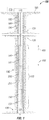
- FIG. 1 is a sectional view of at least a portion of an implementation of a wellsite system 100 according to one or more aspects of the present disclosure.
- the wellsite system 100 comprises a tool string 110 suspended within a wellbore 120 that extends from a wellsite surface 105 into one or more subterranean formations 130.
- the tool string 110 comprises a first portion 140, a second portion 150, and a hydraulic jar, referred to hereinafter as the hydraulic impact apparatus (HIA) 200, coupled between the first portion 140 and the second portion 150, wherein the HIA 200 is operable to impart an impact to at least a portion of the tool string 110.
- the tool string 110 is suspended within the wellbore 120 via conveyance means 160 operably coupled with a tensioning device 170 and/or other surface equipment 175 disposed at the wellsite surface 105.
- the wellbore 120 is depicted in FIG. 1 as being a cased-hole implementation comprising a casing 180 secured by cement 190.
- a casing 180 secured by cement 190 is depicted in FIG. 1 as being a cased-hole implementation comprising a casing 180 secured by cement 190.
- one or more aspects of the present disclosure are also applicable to and/or readily adaptable for utilizing in open-hole implementations lacking the casing 180 and cement 190.
- the tensioning device 170 is operable to apply an adjustable tensile force to the tool string 110 via the conveyance means 160.
- the conveyance means 160 is or comprises wireline, slickline, e-line, coiled tubing, drill pipe, production tubing, and/or other conveyance means, and comprises and/or is operable in conjunction with means for communication between the tool string 110 and the tensioning device 170 and/or one or more other portions of the various surface equipment 175.
- the first and second portions 140 and 150 of the tool string 110 may each be or comprise one or more downhole tools, modules, and/or other apparatus operable in wireline, while-drilling, coiled tubing, completion, production, and/or other implementations.
- the first portion 140 of the tool string 110 also comprises at least one electrical conductor 141 in electrical communication with at least one component of the surface equipment 175, and the second portion 150 of the tool string 110 also comprises at least one electrical conductor 151 in electrical communication with at least one component of the surface equipment 175, wherein the at least one electrical conductor 141 of the first portion 140 of the tool string 110 and the at least one electrical conductor 151 of the second portion 150 of the tool string 110 may be in electrical communication via at least one or more electrical conductors 201 of the HIA 200.
- the one or more electrical conductors 141, 201, 151, and/or others may collectively extend from the conveyance means 160 and/or the first tool string portion 140, into the HIA 200, and perhaps into the second tool string portion 150, and may include various electrical connectors along such path.
- the HIA 200 may be employed to retrieve a portion of the tool string 110 that has become lodged or stuck within the wellbore 120, such as the second portion 150.
- the HIA 200 may be coupled to the second portion 150 of the tool string 110 before the tool string 110 is conveyed into the wellbore, such as in prophylactic applications, or after at least a portion of the tool string 110 ( e.g., the second portion 150) has become lodged or stuck in the wellbore 120, such as in "fishing" applications.
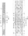
- FIG. 2 is a sectional view of at least a portion of an example implementation of the HIA 200 shown in FIG. 1 .
- the HIA 200 may comprise an electrical conductor 201 in electrical communication with the electrical conductor 141 of the first portion 140 of the tool string 110.
- one or more electrical bulkhead connectors and/or other electrically conductive members 285 may at least partially connect or extend between the electrical conductor 201 of the HIA 200 and the electrical conductor 141 of the first portion 140 of the tool string 110.
- the electrical conductor 201 may also be in electrical communication with the electrical conductor 151 of the second portion 150 of the tool string 110.
- one or more electrical bulkhead connectors and/or other electrically conductive members 280 may extend between the electrical conductor 201 of the HIA 200 and the electrical conductor 151 of the second portion 150 of the tool string 110.
- the electrical conductor 141 of the first portion 140 of the tool string 110 may be in electrical communication with the electrical conductor 151 of the second portion 150 of the tool string 110 via the electrical conductor 201 of the HIA 200 and perhaps one or more electrical bulkhead connectors and/or other electrical connectors 280, 285.
- the electrical conductor 141 of the first portion 140 of the tool string 110, the electrical conductor 201 of the HIA 200, and the electrical conductor 151 of the second portion 150 of the tool string 110, and perhaps one or more other electrical connectors 280, 285, may be in electrical communication with the surface equipment 175, such as via the conveyance means 160.
- the HIA 200 comprises a housing assembly 250 made up of several portions, such as an uphole (hereinafter “upper”) housing 252, an upper housing connector 253 coupled with the upper housing 252, an intermediate housing 254 coupled with the upper housing connector 253, a downhole (hereinafter “lower”) housing connector 255 coupled with the intermediate housing 254, a lower housing 256 coupled with the lower housing connector 255, and a stop section 257 coupled with the lower housing 256.
- Each portion of the housing assembly 250 may be substantially tubular, comprising at least one central passage and/or other passages extending longitudinally therethrough.
- the upper housing 252 may comprise a female-threaded and/or other interface operable to couple the HIA 200 with the first portion 140 of the tool string 110.
- the intermediate housing 254 may comprise a shoulder 230 protruding radially inward, wherein the shoulder 230 may comprise an inside diameter 231 that is substantially smaller than the surrounding portions of the intermediate housing 254.
- the reduced diameter 231 may be smaller in diameter, relative to the surrounding portions of the intermediate housing 254, by an amount ranging between about 10% and about 50%.
- the reduced diameter 231 may range between about 0.5 inches (or about 1.3 centimeters) and about 3.5 inches (or about 8.9 centimeters) less than surrounding portions of the intermediate housing 254, although other values are also within the scope of the present disclosure.
- the HIA 200 may also comprise a mandrel assembly 220 slidably disposed within a central longitudinal passageway extending through one or more components of the housing assembly 250.
- the housing assembly 250 and the mandrel assembly 220 move in axially opposing directions relative to each other.
- the mandrel assembly 220 may comprise several portions coupled together and defining a central bore 221 extending longitudinally therethrough.
- the mandrel assembly 220 may comprise an upper mandrel 222 slidably extending within the upper housing connector 253, an intermediate mandrel 224 coupled with the upper mandrel 222 and slidably extending within the lower housing connector 255, a lower mandrel 226 coupled with the intermediate mandrel 224 and slidably extending within the stop section 257, and a lower joint connector 228 coupled with the lower mandrel 226.
- the upper housing connector 253, the lower housing connector 255, and the stop section 257 may comprise central passageways having smaller inside diameters operable to centralize the mandrel assembly 220 within the housing assembly 250 and/or form fluid seals against the mandrel assembly 220.
- the lower joint connector 228 may comprise a female thread operable to couple the HIA 200 with the second portion 150 of the tool string 110.
- An outwardly extending radial shoulder, boss, flange, and/or other impact feature 225 may be coupled to the lower mandrel 226.
- the first impact feature 225 is operable to impact or collide with an inwardly extending radial shoulder, boss, flange, and/or other impact feature 258, which may be integral to or otherwise carried by the stop section 257 and/or other component of the housing assembly 250.
- annular space 270 may be defined between the mandrel assembly 220 and the housing assembly 250.
- the annular space 270 may comprise a first or lower annulus 271, a second or upper annulus 272, a third or intermediate annulus 273, and a fourth or compensation annulus 275.
- Each annulus 271, 272, 273, 275 of the annular space 270 is operable to hold a fluid (hereinafter "internal fluid") therein, whereby, during operations, the internal fluid may flow between the annuluses in a particular configuration.
- internal fluid hereinafter "internal fluid"
- the housing assembly 250 may comprise one or more fluid sealing elements, such as may prevent the internal fluid from escaping or leaking from within the HIA 200.
- the HIA 200 may also comprise one or more fluid sealing elements that may prevent the internal fluid from communicating between the annuluses 271, 272, 273, 275 until predetermined conditions are met.
- the internal fluid located within the HIA 200 may be fluidly isolated from the first portion 140 of the tool string 110 by the electrical connector 285 disposed within the upper housing 252.
- the electrical connector 285 may be operable to prevent the internal fluid from communicating in the uphole direction 101 from the upper annulus 272 of the HIA 200 into the first portion 140 of the tool string 110.
- the internal fluid located within the HIA 200 may also be fluidly isolated from the second portion 150 of the tool string 110 by the electrical connector 280 disposed within the lower joint connector 228.
- the electrical connector 280 may be operable to prevent fluid communication in the downhole direction 102 from within the lower joint connector 228 of the HIA 200 into the second portion 150 of the tool string 110.
- the internal fluid which may be a hydraulic oil or other fluid, may be fed into the HIA 200 through fill ports 286, 229 located in the upper housing 252 and the lower joint connector 228, respectively.
- substantially all of the air may be extracted to facilitate the internal fluid filling the annular space 270 and other internal spaces of the HIA 200, although other methods may also or instead be utilized to fill the intended portion(s) of the HIA 200 without leaving air therein.
- the fill ports 286, 229 may be closed by plugs 287, 227 respectfully.
- the shoulder 230 may interpose the upper and lower annuluses 272, 271.
- the pressure compensation annulus 275 may be defined between the lower housing connector 255 and the stop section 257.
- a floating piston 277 may be disposed within the pressure compensation annulus 275, such as to define a lower portion 278 of the pressure compensation annulus 275 from an upper portion 276 of the pressure compensation annulus 275.
- the upper portion 276 may be in fluid communication with wellbore fluid located in the wellbore 120, such as through one or more ports 279, and the lower portion 278 may be in fluid communication with the internal fluid previously introduced into the HIA 200.
- the internal fluid may be communicated into and out of the lower portion 278 through one or more mandrel ports 223 extending between the central bore 221 and the lower portion 278.
- the lower housing connector 255 and the floating piston 277 may be operable to prevent the wellbore fluid in the upper portion 276 from leaking into and contaminating the internal fluid contained within the lower portion 278 and other portions of HIA 200. At least a portion of the pressure compensation annulus 275 may thus be utilized for pressure compensation of wellbore fluid and/or internal fluid contained within the HIA 200.
- FIG. 3 is an enlarged view of a portion of the apparatus shown in FIG. 2 .
- the HIA 200 comprises a piston 240 fixedly positioned about the intermediate mandrel 224 and sealingly engaging the shoulder 230 of the intermediate housing 254.
- the piston 240 may by fixedly coupled to the intermediate mandrel 224 via threaded engagement.
- the piston 240 may instead be integrally formed with the intermediate mandrel 224 or fixedly coupled to the intermediate mandrel 224 by other means, including, but not limited to, adhesive, set screw(s), and/or retaining ring(s).
- the piston 240 may be operable to prevent fluid communication between the piston 240 and the intermediate mandrel 224.
- the piston 240 may also comprise an outer surface 241 operable for sealingly engaging the shoulder 230, such as may reduce or prevent fluid communication between the lower annulus 271 and the intermediate annulus 273.
- the outer surface 241 may comprise an outer finish that is sufficiently smooth to form a metal-to-metal seal against the shoulder 230.
- the piston 240 may also comprise an O-ring and/or other fluid-sealing element 244, such as may reduce or prevent fluid communication between the shoulder 230 and the piston 240.
- the piston 240 may also comprise one or more check valves 246 disposed within one or more longitudinal bores 247 extending through the piston 240.
- the check valves 246 may be operable to allow fluid communication through the bores 247 in the downhole direction 102, from the intermediate annulus 273 to the lower annulus 271, and to prevent fluid flow from the lower annulus 271 to the intermediate annulus 273.
- Each longitudinal bore 247 may also comprise a filter 249 disposed therein and operable to prevent contaminants from flowing through and potentially impairing the function of the check valves 246.
- the intermediate annulus 273 may be defined by the space formed between the intermediate connector 253 and the piston 240, wherein the intermediate annulus 273 increases in volume as the housing assembly 250 and the mandrel assembly 220 move apart from each other ( e.g., as the housing assembly 250 moves in the uphole direction 101 with respect to the mandrel assembly 220).
- the intermediate annulus 273 may be fluidly connected with the upper annulus 272 via an annular passageway 274 extending between the intermediate connector 253 and the upper mandrel 222.
- internal fluid may flow between the upper annulus 272 and the intermediate annulus 273 through the annular passageway 274.
- the HIA 200 may further comprise a biasing member 248 positioned within the lower annulus 271 and operable to urge the housing assembly 250 and the mandrel assembly 220 toward a first position, in which the piston 240 is positioned within the shoulder 230 and against the intermediate connector 253.
- FIG. 2 depicts the biasing member 248 as being or comprising a spring urging the piston 240 and the lower housing connector 255 away from each other such that the piston 240 is positioned within the shoulder 230 and against the intermediate connector 253.
- the intermediate housing 254 may comprise a shoulder 230 protruding radially inward from and/or relative to an internal surface of the intermediate housing 254.
- the intermediate housing 254 may also comprise one or more fluid channels 232 extending longitudinally through a portion of the intermediate housing 254 from the upper side of the shoulder 230 to the lower side of the shoulder 230.
- the upper end of the shoulder 230 may fluidly seal against the lower end of the upper housing connector 253 to define an annular channel 234 extending circumferentially between the shoulder 230 and the upper housing connector 253, wherein the upper end of the fluid channels 232 may fluidly connect with the annular channel 234.
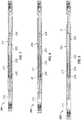
- FIG. 4 is a sectional view of a portion of the HIA 200 shown in FIG. 1 .
- FIG. 5 is an enlarged portion of FIG. 4 that depicts the piston 240, the shoulder 230, the upper housing connector 253, and a pressure relief assembly 260 according to one or more aspects of the present disclosure.
- FIGS. 4 and 5 depict the pressure relief assembly 260 positioned within the upper housing connector 253.
- the pressure relief assembly 260 may control fluid flow from the lower annulus 271 to the upper annulus 272 based on a pressure of the internal fluid in the lower annulus 271 relative to a set, cracking, or relief pressure (hereafter collectively referred to as "set pressure") of the pressure relief assembly 260.
- the pressure relief assembly 260 may comprise multiple pressure relief valves 266a-d operable to prevent communication or relief of internal fluid from the lower annulus 271 to the upper annulus 272 until a set pressure of one or more pressure relief valves 266a-d is exceeded. For example, when the pressure in the lower annulus 271 exceeds the set pressure of at least one of the pressure relief valves 266a-d, the pressure relief assembly 260 may allow fluid communication therethrough.
- FIG. 6 is a sectional view of a portion of the HIA 200 shown in FIG. 5 according to one or more aspects of the present disclosure.
- the pressure relief assembly 260 may comprise multiple pressure relief valves 266a-d positioned within corresponding cavities 263a-d extending into the upper housing connector 253.
- the cavities 263a-d may extend from the exterior surface of the upper housing connector 253 and into the internal portion thereof, without intercepting the annular passageway 274.
- the cavities 263a-d may also be fluidly coupled in parallel between the lower annulus 271 and the upper annulus 272.
- the cavities 263a-d may extend between a first fluid channel 261 and a second fluid channel 262, wherein the fluid channels 261, 262 may extend longitudinally through the upper housing connector 253.
- the first fluid channel 261 may fluidly connect the annular channel 234 with the cavities 263a-d at an intermediate point along the cavities 263a-d, which may be between the outer openings and the inner bottoms of the cavities 263a-d.
- the upper end of the first fluid channel 361 may comprise a plug 267 to prevent internal fluid from communicating into the upper annulus 272.
- the second fluid channel 262 may fluidly connect the cavities 263a-d with the upper annulus 272 at the inner bottoms of the cavities 263a-d.
- Each of the cavities 263a-d may be operable to receive a threaded plug 265a-d therein, wherein each cavity 263a-d may comprise a threaded portion for receiving a threaded plug 265a-d therein.
- the plugs 265a-d may be translated ( e.g ., screwed in or out) along the cavities 263a-d to block or unblock ( i.e., prevent or allow) fluid communication between the first fluid channel 261 and each of the corresponding cavities 263a-d.
- the internal fluid may communicate into the fourth cavity 263d and, therefore, communicate with the fourth relief valve 266d.
- the third plug 265c is translated away from the first channel 261 and the fourth plug 265d is also translated away from the first channel 261
- the internal fluid may communicate into the third cavity 263c and, therefore, communicate with the third relief valve 266c.
- the second plug 265b is translated away from the first channel 261 and the third and fourth plugs 265c, 265d are also translated away from the first channel 261
- the internal fluid may communicate into the second cavity 263b and, therefore, communicate with the second relief valve 266b.
- the internal fluid may communicate into the first cavity 263a and, therefore, communicate with the first relief valve 266a.
- Each pressure relief valve 266a-d may be or comprise a cartridge type pressure relief valve that may be insertable into the cavities 263a-d. Each pressure relief valve 266a-d may comprise a different set pressure to allow internal fluid to communicate or relieve through each cavity 263a-d at different predetermined pressures. Such configuration may allow the pressure relief assembly 260 to allow internal fluid to communicate or relieve through the pressure relief assembly 260 from the lower annulus 271 to the upper annulus 272 at different predetermined pressures, allowing the set pressure to be adjusted without removing the pressure relief assembly 260 or the individual pressure relief valves 266a-d from the HIA 200.
- each plug 265a-d may prevent fluid communication into a blocked cavity and any other cavity located downstream ( i.e., in the uphole direction 101) along the first channel 261, the relief valves 266a-d may be inserted into the cavities 263a-d in order of increasing set pressure, wherein the first pressure relief valve 266a comprises a lowest set pressure and the fourth pressure relief valve 266d comprises a highest set pressure.
- the first pressure relief valve 266a may comprise a set pressure of about 500 pounds per square inch (psi)
- the second pressure relief valve 266b may comprise a set pressure of about 1000 psi
- the third pressure relief valve 266c may comprise a set pressure of about 2000 psi
- the fourth pressure relief valve 266d may comprise a set pressure of about 3000 psi.
- other set pressures, intervals, and ranges are also within the scope of the present disclosure.
- the cavities 263a-d may receive therein burst disks, hydraulic fuses, and/or other types of pressure relief devices known in the art.
- FIGS. 4 and 5 show the pressure relief assembly 260 comprising four sets of cavities 263a-d, pressure relief valves 266a-d, and plugs 265a-d, it should be understood that the pressure relief valve 260 may comprise two, three, five, or more sets of cavities, pressure relief valves, and plugs, which may comprise the same or similar structure and/or function as described herein.
- FIGS. 7, 8, and 9 are sectional views of the HIA 200 shown in FIG. 1 in various stages of operation according to one or more aspects of the present disclosure.
- the housing assembly 250 is movable with respect to the mandrel assembly 220 between the first or a latched position, shown in FIG. 7 , a second or release position, shown in FIG. 8 , and a third or impact position, shown in FIG. 9 .
- a tension load may be applied to the HIA 200 while the HIA 200 is in the latched position ( FIG. 7 ), in which the housing assembly 250 and the mandrel assembly 220 are retracted and latched together.
- tension When tension is applied to the HIA 200, pressure increases within the lower annulus 271 as the internal fluid is sealed therein by the piston 240 and the lower housing connector 255 to prevent the housing assembly 250 from moving with respect to the mandrel assembly 220.
- the pressure relief assembly 260 may also prevent the internal fluid from communicating from the lower annulus 271 into the upper annulus 272.
- the pressure relief valves 266a-d may block the internal fluid from communicating from the lower annulus 271 into the upper annulus 272 through an internal fluid passageway system comprising the fluid channels 232, 234, 261, 262 and the cavities 263a-d, which collectively extend between the lower annulus 271 and the upper annulus 272.
- the pressure relief assembly 260 may be set to allow internal fluid to escape from the lower annulus 271 at a desired pressure, which may correspond to a tension load that is believed to be sufficient or necessary to free the stuck tool string.
- a desired pressure which may correspond to a tension load that is believed to be sufficient or necessary to free the stuck tool string.
- at least one of the pressure relief valves 266a-d may shift open to allow fluid communication through a corresponding cavity 263a-d to, therefore, allow the housing assembly 250 to move with respect to the stationary mandrel assembly 220.
- the internal fluid may first flow from the upper annulus 271 into and through the fluid channel 232, as indicated by the arrows 15.
- the internal fluid may then flow into the annular channel 234 between the shoulder 230 and the upper housing connector 253.
- the internal fluid may flow into the first fluid channel 261 and into one or more of the cavities 263a-d to bypass one or more cracked or opened pressure relief valves 266a-d.
- the internal fluid may relieve or communicate into the upper annulus 272 through the second fluid channel 262.
- FIG. 5 depicts the third and fourth plugs 265c, 265d translated away from the first fluid channel 261, to allow the third relief valve 263c to open and allow internal fluid to communicate through the third cavity 263c.
- the internal fluid may be metered as it passes from the lower annulus 271 to the upper annulus 272, slowing the movement of the housing assembly 250 with respect to the mandrel assembly 220.
- the resulting fluid metering may create a time delay from when the housing assembly 250 starts to move until the time when the shoulder 230 moves past the piston 240, as depicted in FIGS. 8 and 10 , wherein FIG.
- FIG. 10 depicts an enlarged portion of the HIA 200 shown in FIG. 8 .
- Another flow control valve such as a metering valve (not shown), may be positioned along one of the fluid channels 232, 234, 261, and 262 to further control the rate of fluid flow therethrough if additional time delay or fluid metering is desired.
- the housing assembly 250 moves in the uphole direction 101 as the mandrel assembly 220 remains essentially static, being attached to the second portion 150 of the tool string 110 that is stuck in the wellbore 120.
- the intermediate annulus 273 increases in volume as the internal fluid moves therein from the upper annulus 272 through the annular passageway 274.
- the annular space between the piston 240 and the intermediate housing 254 opens significantly, allowing the internal fluid to bypass the piston 240 and move from the lower annulus 271 to the intermediate annulus 273 at a substantially higher flow rate. Therefore, when the shoulder 230 moves past the piston 240, the housing assembly 250 may move essentially freely with respect to the mandrel assembly 220.
- the tool string 110 and/or the conveyance means 160 may then contract, accelerating the housing 250 in the uphole direction 101 until the piston 240 and the shoulder 230 move sufficiently far apart and the second impact feature 258 impacts the first impact feature 225, thus creating an impact intended to free the second portion 150 of the tool string 110.
- the impact between the second impact feature 258 and the first impact feature 225 is depicted in FIGS. 9 and 11 , wherein FIG. 11 depicts an enlarged portion of the HIA 200 shown in FIG. 9 .
- the higher the tension force applied to the HIA 200 which may be proportional to the set pressure of the pressure relief assembly 260, the faster the acceleration of the housing assembly 250, and the greater the impact force generated by the first and second impact shoulders 225, 258.
- FIGS. 7, 8, and 9 further show that, during operations, the biasing member 248 is compressed as the housing assembly 250 moves with respect to the mandrel assembly 220.
- the biasing spring 248 urges or pushes the piston 240 and the lower housing connector 255 away from each other to urge the housing assembly 250 and the mandrel assembly 220 toward the first position, thus resetting the HIA 200 to deliver another impact.
- the internal fluid may communicate from the intermediate annulus 273 into the lower annulus 271 through the one or more check valves 246 disposed in the one or more longitudinal bores 247 of the piston 240, as shown in FIG. 3 .
- the ability to reset the HIA 200 using the biasing member 248 may be beneficial when, for example, external compression forces are not available or are insufficient to move the housing assembly 250 and the mandrel assembly 220 to the first position.
- FIG. 12 is a sectional view of at least a portion of an example implementation of the HIA 200 shown in FIG. 1 according to one or more aspects of the present disclosure.
- the HIA 200 may comprise a pressure relief assembly 360, operable to allow fluid communication from the lower annulus 271 to the upper annulus 272 at a predetermined set relief pressures.
- the pressure relief assembly 360 may comprise multiple pressure relief valves 366a-d positioned within corresponding cavities 363a-d extending into the upper housing connector 253.
- the cavities 363a-d may extend from the exterior surface of the upper housing connector 253 and into the internal portion thereof, without intercepting the annular passageway 274.
- the cavities 363a-d may also be fluidly coupled in parallel between the lower annulus 271 and the upper annulus 272.
- the cavities 363a-d may extend between a first fluid channel 361 and a second fluid channel 362, wherein the fluid channels 361, 362 extend longitudinally through the upper housing connector 253.
- the first fluid channel 361 may fluidly connect the annular channel 234 and the cavities 363a-d at an intermediate point along the cavities 363a-d between the outer openings and the inner bottoms of the cavities 363a-d.
- the upper end of the first fluid channel 361 may comprise a plug 367 to prevent internal fluid from communicating into the upper annulus 272.
- the second fluid channel 362 may fluidly connect the upper annulus 272 and the cavities 363a-d at the inner bottoms of the cavities 363a-d.
- Each of the cavities 363a-d may be operable to receive a threaded plug 365a-d therein, wherein each cavity 363a-d may comprise a threaded portion for receiving a threaded plug 365a-d therein.
- the plugs 365a-d may be translated along the cavities 363a-d to block or unblock fluid communication between the first channel 361 and each of the corresponding cavities 363a-d.
- the internal fluid may communicate into the fourth cavity 363d and, therefore, communicate with the fourth relief valve 366d.
- the third plug 365c is translated away from the first channel 361 and the fourth plug 365d is also translated away from the first channel 361
- the internal fluid may communicate into the third cavity 363c and, therefore, communicate with the third relief valve 366c.
- the second plug 365b is translated away from the first channel 361 and the third and fourth plugs 365c, 365d are also translated away from the first channel 361
- the internal fluid may communicate into the second cavity 363b and, therefore, communicate with the second relief valve 366b.
- the internal fluid may communicate into the first cavity 363a and, therefore, communicate with the first relief valve 366a.
- Each pressure relief valve 366a-d may be or comprise a cartridge type pressure relief valve that may be insertable into cavities 363a-d. Each pressure relief valve 366a-d may comprise a different set pressure to allow internal fluid to communicate or relieve through each cavity 363a-d at different predetermined pressures. Such configuration may allow the pressure relief assembly 360 to allow internal fluid to communicate or relieve through the pressure relief assembly 360 from the lower annulus 271 to the upper annulus 272 at different predetermined pressures.
- each plug 365a-d may prevent internal fluid communication into the blocked cavity and any other cavity located downstream ( e.g., in the uphole direction 101), along the first channel 361, the relief valves 366a-d may be inserted into the cavities 363a-d in order of increasing set pressure, wherein the first pressure relief valve 366a comprises the lowest set pressure and the fourth pressure relief valve 366d comprises the highest set pressure.
- the pressure relief valves 366a-d may comprise set relief pressures that are the same or similar to set pressures of the pressure relief valves 266a-d of the pressure relief assembly 260.
- the pressure relief valves 366a-d may comprise set pressures that are higher than the set pressures of the pressure relief valves of 266a-d.
- the first pressure relief valve 366a may comprise a set pressure of about 3500 psi
- the second pressure relief valve 366b may comprise a set pressure of about 4000 psi
- the third pressure relief valve 366c may comprise a set pressure of about 5000 psi
- the fourth pressure relief valve 366d may comprise a set pressure of about 6000 psi.
- other set pressures, intervals, and ranges are also within the scope of the present disclosure.
- the cavities 363a-d may receive therein burst disks, hydraulic fuses, and/or other types of pressure relief devices (not shown) known in the art.
- FIG. 12 shows the pressure relief assembly 360 comprising four sets of cavities 363a-d, pressure relief valves 366a-d, and plugs 365a-d, it should be understood that the pressure relief valve 360 may comprise two, three, five, or more sets of cavities, pressure relief valves, and plugs, which can function or interact in the same or similar manner as described herein.
- the general structure and function of the pressure relief assembly 360 may be the same or similar to that of the pressure relief assembly 260 described above.
- the pressure relief assembly 360 may further comprise a flow control and/or shut-off valve 370 disposed along the second fluid channel 362, such as to selectively prevent internal fluid from communicating from the lower annulus 271 to the upper annulus 272.
- FIG. 12 depicts a solenoid operated shut-off valve 370 positioned along the second fluid channel 362 between the first cavity 363a and the upper annulus 272.
- the shut-off valve 370 may comprise a blocking portion 374 operable for blocking fluid flow through the second fluid channel 362, wherein the blocking portion 374 may be selectively actuated by a solenoid 372 to shift between an open-flow positon (i.e., allowing fluid flow therethrough) and a closed-flow position ( i.e., not allowing fluid flow therethrough).
- a solenoid 372 When shifted to the open-flow position, the blocking portion 374 allows internal fluid to communicate through the second flow channel 362 into the upper annulus 272.
- the solenoid may be positioned in a cavity 364 extending into the upper housing connector 253 and retained therein by a solenoid retainer plate 368.
- the pressure relief assembly 360 may allow internal fluid to communicate from the lower annulus 271 to the upper annulus 272 if the pressure in the lower annulus 271 exceeds the set pressure of one or more pressure relief valves 366a-d that are exposed to the first fluid channel 361 and if the shut-off valve 370 is shifted to the open-flow position. Therefore, although the pressure in the lower annulus 271 may exceed the set pressure of one or more of the pressure relief valves 366a-d, internal fluid may not communicate from the lower annulus 271 to the upper annulus 272 through the fluid passageway system comprising the fluid channels 232, 234, 361, 362 and the cavities 363a-d, until the shut-off valve 370 is shifted to the open-flow position.
- the HIA 200 may comprise a different flow control valve to remotely control fluid communication out of the lower annulus 271, including pilot-operated valves, cartridge valves, poppet valves, plunger valves, diaphragm valves, and/or other examples of flow control devices known in the art.
- the shut-off valve 370 may comprise a normally closed configuration, wherein the shut-off valve 370 may be operable to remain in the closed-flow position when not actuated by the solenoid 372 and shift to the open-flow position when actuated by the solenoid 372.
- the shut-off valve 370 may be operable to detect an electrical characteristic of the electrical conductor 201 to actuate the blocking portion 374 to the open-flow position to allow fluid communication through the pressure relief assembly 360 when the pressure in the lower annulus exceeds the set pressure of at least one of the pressure relief valves 366a-d.
- the blocking member 374 of the shut-off valve 370 does not allow fluid communication through the second fluid channel 362 and, therefore, does not allow fluid communication through the pressure relief assembly 360 even when the pressure in the lower annulus exceeds the set pressure of at least one pressure relief valve 366a-d.
- the electrical characteristic detected by the shut-off valve 370 may be a substantially non-zero voltage and/or current, such as in implementations in which the electrical characteristic is a voltage substantially greater than about 0.01 volts and/or a current substantially greater than about 0.001 amperes.
- the electrical characteristic may be a voltage substantially greater than about 0.1 volts and/or a current substantially greater than about 0.01 amperes.
- the solenoid 372 of the shut-off valve 370 may receive an electrical characteristic from another source, including, for example, another electrical conductor (not shown) extending between the surface and the HIA 200 or a battery (not shown) located within the HIA 200.
- the pressure relief assembly 360 may be operable to set additional relief pressures. For example, referring to FIGS. 5 and 12 , if the desired pressure at which to create an impact is 5000 psi, plugs 265a-d of the pressure relief assembly 260 may be translated (not shown) to fluidly isolate (e.g., plug off) the cavities 263a-d from the first channel 261. However, since the fourth plug 265d fluidly isolates the cavities 263a-d from the first fluid channel 261, it may only be necessary to translate the fourth plug 265d to also isolate the remaining cavities 263a-d.
- plugs 365a, 365b of the pressure relief assembly 360 may be translated to fluidly isolate the first and second cavities 363a, 363b from the first channel 361.
- the second plug since the second plug fluidly isolates cavities 363a, 363b from the first fluid channel 361, it may only be necessary to translate the second plug 365b to also isolate the first cavity 363a.
- the third and fourth plugs 365c, 365d may be translated away from the first fluid channel 361 to allow fluid communication with the third cavity 363c and the third pressure relief valve 366c.
- the HIA 200 is configured to allow internal fluid from the lower annulus 271 to communicate with the third and the fourth pressure relief valves 366c, 366d.
- the third pressure relief valve 366d may shift to allow internal fluid to communicate through the third cavity 363c and, therefore, the second fluid channel 362, as indicated by the arrows 16. It should be noted that internal fluid will be allowed to communicate through the third cavity 363c only if the shut-off valve is in the open-flow position.
- both pressure relief assemblies 260, 360 may be utilized simultaneously.
- the pressure relief assembly 360 may be operable to set a desired pressure at which the HIA 200 creates an impact, while the pressure relief assembly 260 may be operable for safety or fail-safe purposes.
- the pressure relief valves 366a-d of the pressure relief assembly 360 may comprise set pressures of 500 psi, 1000 psi, 2000 psi, and 3000 psi, respectively, while the pressure relief valves 266a-d of the pressure relief assembly 260 may comprise set pressures of 3500 psi, 4000 psi, 5000 psi, and 6000 psi, respectively.
- the pressure relief assembly 260 may relieve internal fluid from the lower annulus 271 to the upper annulus 272 when the pressure in the lower annulus 271 reaches a predetermined set pressure of the pressure relief assembly 260, if the internal fluid in the lower annulus 271 did not first relieve through pressure relief assembly 360 at its predetermined set pressure, which is lower than the set pressure of the pressure relief assembly 260.
- the pressure relief assembly 360 may not relieve internal fluid at the set pressure if, for example, the shut-off valve is not actuated to the open-flow position or one or more of the pressure relief valves 366a-d are stuck in the closed-flow position.
- the pressure relief assembly 360 may be operable to remotely trigger the HIA 200 to create an impact.
- the shut-off valve may be operable to trigger the impact at any time after the pressure in the lower annulus 271 exceeds 1000 psi. Therefore, the electrical conductor 201 may actuate the shut-off valve 370 to the open-flow position at, for example, 1500 psi, to relieve the internal fluid in the lower annulus 271 to the upper annulus 272 to cause the housing assembly 250 to move with respect to the mandrel assembly 220 and, therefore, trigger the impact.
- the electrical conductor 201 may continuously actuate the shut-off valve 370 to the open-flow position, in which case the internal fluid in the lower annulus 271 may relieve to the upper annulus 272 as soon as the fluid pressure in the lower annulus 271 exceeds the set pressure of the pressure relief assembly 360.
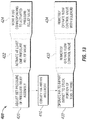
- FIG. 13 is a flow-chart diagram of at least a portion of an example implementation of a method (400) of operation utilizing the HIA 200 according to one or more aspects of the present disclosure, such as in the example operating environment depicted in FIG. 1 , among others within the scope of the present disclosure.
- the method (400) may comprise conveying (410) the HIA 200 within the wellbore 120 in a downhole direction 102 with the HIA 200 coupled between the first portion 140 and the second portion 150 of the tool string 110, whether as part of the tool string 110 before the tool string 110 gets stuck, or after the tool string 110 is already stuck in the wellbore 120.
- the HIA 200 may be in the configuration shown in FIGS. 2 and 7 , in which the HIA 200 is in the first or reset position.
- the method (400) may further comprise operating (430) the HIA 200 to impart an impact to the second portion 150 of the tool string 110.
- the method (400) may further comprise adjusting (420) one or more set pressures of the pressure relief assembly 260, 360 prior to conveying the tool string 110 within the wellbore 120.
- the pressure relief assembly 260, 360 comprises multiple individually activated pressure relief valves 266a-d, 366a-d. Therefore, adjusting (420) the set relief pressure of the pressure relief assembly 260, 360 may comprise activating (422) at least one of a plurality of pressure relief valves 266a-d, 366a-d.
- the pressure relief assembly 260, 360 may further comprise a plurality of plugs 265a-d, 365a-d, each operable with a corresponding one of the plurality of pressure relief valves 266a-d, 366a-d.
- activating (422) at least one of the plurality of pressure relief valves 266a-d, 366a-d may comprise moving (424) a corresponding one of the plurality of plugs 265a-d, 365a-d to permit fluid communication between the lower and upper annulus portions 271, 272 via the at least one activated pressure relief valve 266a-d, 366a-d.
- the HIA 200 may further comprise a flow control valve or a shut-off valve 370, wherein operating the HIA 200 comprises remotely operating (432) the shut-off valve 370 to permit fluid communication through the pressure relief assembly 360 after a predetermined tension is applied to the HIA 200.
- Remotely operating (432) the shut-off valve 370 may comprise remotely operating (434) the shut-off valve with a solenoid 372 to permit fluid communication through the pressure relief assembly 360 after a predetermined tension is applied to the HIA 200.
- a hydraulic jar coupled between opposing first and second portions of a downhole tool string
- the hydraulic jar comprises: a housing comprising a shoulder protruding radially inward from an internal surface of the housing; a shaft disposed within the housing, wherein the housing and the shaft move axially relative to each other, and wherein the shoulder axially interposes first and second portions of an annulus formed between the shaft and the housing; a piston fixedly positioned about the shaft and fluidly sealed against the shoulder; and a pressure relief device controlling fluid flow from the first annulus portion to the second annulus portion based on a pressure of the fluid in the first annulus portion relative to a set pressure of the pressure relief device.
- the housing may be substantially tubular.
- the fluid may be hydraulic oil.
- the axially relative movement of the housing and the shaft may be between: a first position in which the piston fluidly seals against the shoulder; and a second position in which the piston is longitudinally offset from the shoulder, thus permitting the fluid to flow from the first annulus portion to the second annulus portion via a third annulus portion between the shoulder and the shaft.
- the piston When the housing and the shaft are in the first position, the piston may prevent fluid flow through the third annulus portion.
- the pressure in the first annulus portion exceeds the set pressure of the pressure relief device, the fluid may be communicated from the first annulus portion to the second annulus portion via the pressure relief device.
- the housing and the shaft may move away from the first position and toward the second position in response to the fluid being communicated from the first annulus portion to the second annulus portion via the pressure relief device.
- the shaft may comprise a first impact feature
- the housing may comprise a second impact feature
- the first and second impact features may impact when the housing and the shaft are in the second position.
- the pressure relief device may comprise a plurality of pressure relief valves each selectable to relieve the fluid from the first annulus portion to the second annulus portion.
- the plurality of pressure relief valves may be fluidly coupled in parallel between the first and second annulus portions.
- Such apparatus may further comprise a plurality of plugs each movable to selectively prevent communication between the fluid and a corresponding one of the plurality of pressure relief valves.
- Each of the plurality of pressure relief valves may have a substantially different set pressure relative to each of the other pressure relief valves.
- the plurality of pressure relief valves may comprise: a first pressure relief valve having a first set pressure of about 500 pounds per square inch (psi); a second pressure relief valve having a second set pressure of about 1000 psi; and a third pressure relief valve having a third set pressure of about 2000 psi.
- the apparatus may further comprise a biasing member positioned in the first annulus portion operable to urge the housing and the shaft towards the first position.
- the present disclosure also introduces an apparatus comprising: a hydraulic jar coupled between opposing first and second portions of a downhole tool string, wherein the hydraulic jar comprises: a housing comprising a first longitudinal bore extending therethough, wherein a substantial portion of the first longitudinal bore has a first diameter; a mandrel having a second longitudinal bore extending therethough, wherein an annulus formed around the mandrel within the first longitudinal bore comprises a fluid, and wherein the housing and the mandrel are moveable relatively in first and second axially opposing directions; an electrical conductor electrically coupling the first and second portions of the downhole tool string and extending through the second longitudinal bore; a piston carried with the mandrel and fluidly sealing against a reduced diameter section of the housing, wherein the reduced diameter section has a second diameter that is substantially less than the first diameter of the first longitudinal bore, and wherein the reduced diameter section collectively interposes first and second longitudinally offset portions of the annulus; and a pressure relief device controlling fluid communication from the first annulus portion
- the pressure relief device may prevent fluid communication from the first annulus portion to the second annulus portion when the pressure of fluid in the first annulus portion is less than a first pressure.
- the pressure relief device may permit fluid communication from the first annulus portion to the second annulus portion when the pressure of fluid in the first annulus portion is greater than the first pressure and less than a second pressure and the electrical status is a first electrical status but not a second electrical status.
- the pressure relief device may permit fluid communication from the first annulus portion to the second annulus portion when the pressure of fluid in the first annulus portion is greater than the second pressure and the electrical status is the second electrical status but not the first electrical status.
- the first electrical status may comprise the existence of a substantially non-zero voltage or current
- the second electrical status may comprise the existence of substantially no voltage or current.
- the first electrical status may comprise the existence of at least one of: a voltage greater than about 0.01 volts; and a current greater than about 0.001 amperes; and the second electrical status may comprise the existence of each of: a voltage less than about 0.01 volts; and a current less than about 0.001 amperes.
- the second electric status may comprise the existence of substantially no voltage or current. At least one of the first and second pressures may be adjustable without removing the pressure relief device from the apparatus.
- the pressure relief device may comprise a plurality of pressure relief valves.
- the plurality of pressure relief valves may be collectively hydraulically coupled in parallel between the first and second annulus portions.
- Such hydraulic jar may further comprise a plurality of plugs, wherein each of the plurality of plugs is movable to selectively prevent communication between the fluid in the first annulus portion and a corresponding one of the plurality of pressure relief valves.
- Each of the plurality of pressure relief valves may have a substantially different set pressure relative to each of the other pressure relief valves.
- the plurality of pressure relief valves may comprise: a first pressure relief valve having a first set pressure of about 500 pounds per square inch (psi); a second pressure relief valve having a second set pressure of about 1000 psi; and a third pressure relief valve having a third set pressure of about 2000 psi.
- the pressure relief device may selectively prevent fluid communication from the first annulus portion to the second annulus portion based on hydraulic pressure of the fluid within the first annulus portion.
- the fluid may communicate from the first annulus portion to the second annulus portion when a hydraulic pressure of the fluid in the first annulus portion exceeds the set pressure of the pressure relief device, thereby allowing the mandrel to move in the first direction.
- the mandrel may comprise a first impact feature
- the housing may comprise a second impact feature
- the first and second impact features may impact each other after the piston and shoulder move sufficiently far apart.
- the hydraulic jar may further comprise a biasing member positioned about the mandrel and operable to resist relative movement of the piston and the reduced diameter section of the housing away from each other.
- the present disclosure also introduces a method comprising: conveying a tool string within a wellbore in a downhole direction, wherein a hydraulic jar coupled between uphole and downhole portions of the tool string comprises: a housing comprising a shoulder protruding radially inward from an internal surface of the housing; a shaft disposed within the housing, wherein the housing and the shaft move axially relative to each other, and wherein the shoulder axially interposes first and second portions of an annulus formed between the shaft and the housing; a piston fixedly positioned about the shaft and fluidly sealed against the shoulder; and a pressure relief device controlling fluid flow from the first annulus portion to the second annulus portion based on a pressure of the fluid in the first annulus portion relative to a set pressure of the pressure relief device; and operating the hydraulic jar to impart an impact to the downhole portion of the tool string.
- the method may further comprise adjusting a set pressure of the pressure relief device prior to conveying the tool string within the wellbore and operating the hydraulic jar to impart the impact to the downhole portion of the tool string.
- the pressure relief device may comprise a plurality of individually activated pressure relief valves, and adjusting the set pressure of the pressure relief device may comprise activating at least one of a plurality of pressure relief valves.
- the pressure relief device may further comprise a plurality of plugs each operable with a corresponding one of the plurality of relief valves, and activating at least one of the plurality of pressure relief valves may comprise moving a corresponding one of the plurality of plugs to permit fluid communication between the first and second annulus portions via the at least one activated pressure relief valve.
- the hydraulic jar may further comprise a flow control valve, and operating the hydraulic jar may comprise remotely operating the flow control valve to permit fluid communication through the pressure relief device after a predetermined tension is applied to the hydraulic jar.
- Remotely operating the flow control valve may comprise remotely operating the flow control valve with a solenoid to permit fluid communication through the pressure relief device after a predetermined tension is applied to the hydraulic jar.
Landscapes
- Life Sciences & Earth Sciences (AREA)
- Geology (AREA)
- Engineering & Computer Science (AREA)
- Mining & Mineral Resources (AREA)
- Physics & Mathematics (AREA)
- Environmental & Geological Engineering (AREA)
- Fluid Mechanics (AREA)
- Marine Sciences & Fisheries (AREA)
- General Life Sciences & Earth Sciences (AREA)
- Geochemistry & Mineralogy (AREA)
- Earth Drilling (AREA)
- Shearing Machines (AREA)
- Percussive Tools And Related Accessories (AREA)
- Hand Tools For Fitting Together And Separating, Or Other Hand Tools (AREA)
Claims (15)
- Vorrichtung, umfassend eine hydraulische Schlagschere (200) zum Koppeln zwischen gegenüberliegenden ersten und zweiten Abschnitten (140, 150) eines Untertagewerkzeugstrangs (110), wobei die hydraulische Schlagschere (200) Folgendes umfasst:ein Gehäuse (250), das eine Schulter (230) umfasst, die von einer Innenfläche des Gehäuses radial nach innen vorsteht;eine Welle (220), die innerhalb des Gehäuses angeordnet ist, wobei sich das Gehäuse (250) und die Welle (220) relativ zueinander axial bewegen, und wobei die Schulter (230) einen ersten und zweiten Abschnitt (271, 272) eines Rings (270), der zwischen der Welle (220) und dem Gehäuse (250) gebildet ist, axial einfügt;einen Kolben (240), der fest mit der Welle (220) gekoppelt und fluidisch gegen die Schulter (230) abgedichtet ist; dadurch gekennzeichnet, dass die hydraulische Schlagschere (200) ferner eine Druckentlastungsvorrichtung (260) umfasst, die Fluidfluss von dem ersten Ringabschnitt (271) zu dem zweiten Ringabschnitt (272) basierend auf einem Druck des Fluids in dem ersten Ringabschnitt (271) relativ zu einem Solldruck der Druckentlastungsvorrichtung (260) steuert, wobei die Druckentlastungsvorrichtung (260) eine Vielzahl von Druckentlastungsventilen (266a-d) umfasst, die jeweils auswählbar sind, um das Fluid von dem ersten Ringabschnitt (271) zu dem zweiten Ringabschnitt (272) zu entlasten.
- Vorrichtung nach Anspruch 1, wobei die hydraulische Schlagschere (200) ferner eine Vielzahl von Stopfen (265a-d) umfasst, die jeweils bewegbar sind, um Kommunikation zwischen dem Fluid und einem entsprechenden aus der Vielzahl von Druckentlastungsventilen (266a-d) selektiv zu verhindern.
- Vorrichtung nach Anspruch 1, wobei jedes aus der Vielzahl von Druckentlastungsventilen (266a-d) einen im Wesentlichen anderen Solldruck relativ zu jedem der anderen Druckentlastungsventile (266a-d) aufweist.
- Vorrichtung nach Anspruch 1, wobei die axial relative Bewegung des Gehäuses (250) und der Welle (220) zwischen Folgendem bewegbar ist: einer ersten Position, in der der Kolben (240) fluidisch gegen die Schulter (230) abdichtet; und einer zweiten Position, in der der Kolben (240) längs von der Schulter versetzt ist, wodurch ermöglicht wird, dass das Fluid von dem ersten Ringabschnitt (271) über einen dritten Ringabschnitt (273) zwischen der Schulter (230) und der Welle (220) zu dem zweiten Ringabschnitt (272) fließt, wobei, wenn sich das Gehäuse (250) und die Welle (220) in der ersten Position befinden, der Kolben (240) Fluidfluss durch den dritten Ringabschnitt (273) verhindert; und wobei, wenn der Druck in dem ersten Ringabschnitt (271) den Solldruck der Druckentlastungsvorrichtung (260) übersteigt, das Fluid von dem ersten Ringabschnitt (271) über die Druckentlastungsvorrichtung (260) zu dem zweiten Ringabschnitt (272) kommuniziert wird.
- Vorrichtung nach Anspruch 1, wobei die Vielzahl von Druckentlastungsventilen (266a-d) parallel zwischen dem ersten und zweiten Ringabschnitt (271, 272) fluidisch gekoppelt ist.
- Vorrichtung nach Anspruch 1, wobei die Vielzahl von Druckentlastungsventilen (266a-d) Folgendes umfasst: ein erstes Druckentlastungsventil (266a), das einen ersten Solldruck von etwa 500 Pfund pro Quadratzoll (psi) aufweist; ein zweites Druckentlastungsventil (266b), das einen zweiten Solldruck von etwa 1000 psi aufweist; und ein drittes Druckentlastungsventil (266c), das einen dritten Solldruck von etwa 2000 psi aufweist.
- Vorrichtung nach Anspruch 1, ferner umfassend ein Vorspannelement (248), das in dem ersten Ringabschnitt (271) positioniert und bedienbar ist, um das Gehäuse (250) und die Welle (220) in Richtung der ersten Position zu drängen.
- Verfahren, umfassend:Fördern eines Werkzeugstrangs (110) innerhalb eines Bohrlochs (120) in einer Untertagerichtung, wobei eine hydraulische Schlagschere (200), die zwischen einem Übertage- und Untertageabschnitt (140, 150) des Werkzeugstrangs (110) gekoppelt ist, ein Gehäuse (250), das eine Schulter (230) umfasst, die von einer Innenfläche des Gehäuses radial nach innen vorsteht; eine Welle (220), die innerhalb des Gehäuses (250) angeordnet ist, wobei sich das Gehäuse (250) und die Welle (220) relativ zueinander axial bewegen, und wobei die Schulter (230) einen ersten und zweiten Abschnitt (271, 272) eines Rings (270), der zwischen der Welle (220) und dem Gehäuse (250) gebildet ist, axial einfügt; einen Kolben (240), der fest um die Welle positioniert und fluidisch gegen die Schulter abgedichtet ist; und eine Druckentlastungsvorrichtung (260) umfasst, die Fluidfluss von dem ersten Ringabschnitt (271) zu dem zweiten Ringabschnitt (272) basierend auf einem Druck des Fluids in dem ersten Ringabschnitt (271) relativ zu einem Solldruck der Druckentlastungsvorrichtung (260) steuert, wobei die Druckentlastungsvorrichtung (260) eine Vielzahl von einzeln aktivierten Druckentlastungsventilen (266a-d) umfasst;Betätigen der hydraulischen Schlagschere (200), um dem Untertageabschnitt (150) des Werkzeugstrangs (110) einen Impuls zu verleihen; undEinstellen eines Solldrucks der Druckentlastungsvorrichtung (260) durch Aktivieren von zumindest einem aus der Vielzahl von einzeln aktivierten Druckentlastungsventilen (266a-d) vor dem Fördern des Werkzeugstrangs (110) innerhalb des Bohrlochs und dem Betätigen der hydraulischen Schlagschere (200), um dem Untertageabschnitt (150) des Werkzeugstrangs (110) den Impuls zu verleihen.
- Verfahren nach Anspruch 8, wobei die Druckentlastungsvorrichtung (260) ferner eine Vielzahl von Stopfen (265a-d) umfasst, die jeweils mit einem entsprechenden aus der Vielzahl von Entlastungsventilen (266a-d) betätigbar sind, und wobei das Aktivieren von zumindest einem aus der Vielzahl von Druckentlastungsventilen (266a-d) das Bewegen eines entsprechenden aus der Vielzahl von Stopfen (265a-d) umfasst, um Fluidkommunikation zwischen dem ersten und zweiten Ringabschnitt (271, 272) über das zumindest eine aktivierte Druckentlastungsventil (266a-d) zu ermöglichen.
- Verfahren nach Anspruch 8, wobei die hydraulische Schlagschere (200) ferner ein Flusssteuerventil (370) umfasst und wobei das Betätigen der hydraulischen Schlagschere (200) das Fernbetätigen des Flusssteuerventils (370) umfasst, um Fluidkommunikation durch die Druckentlastungsvorrichtung (260) zu ermöglichen, nachdem eine vorbestimmte Spannung an die hydraulische Schlagschere (200) angelegt wird.
- Verfahren nach Anspruch 10, wobei das Fernbetätigen des Flusssteuerventils (370) das Fernbetätigen des Flusssteuerventils (370) mit einem Solenoid (372) umfasst, um Fluidkommunikation durch die Druckentlastungsvorrichtung (260) zu ermöglichen, nachdem eine vorbestimmte Spannung an die hydraulische Schlagschere (200) angelegt wird.
- Vorrichtung nach Anspruch 1, wobei jedes der Druckentlastungsventile (266a-d) innerhalb eines Hohlraums (363a-d) angeordnet ist, der sich von einer Außenfläche des Gehäuses (250) erstreckt.
- Vorrichtung nach Anspruch 2, wobei jeder der Stopfen (265a-d) innerhalb eines Hohlraums (363a-d) angeordnet ist, der sich von einer Außenfläche des Gehäuses (250) erstreckt.
- Verfahren nach Anspruch 8, wobei jedes der Druckentlastungsventile (266a-d) innerhalb eines Hohlraums (363a-d) angeordnet ist, der sich von einer Außenfläche des Gehäuses (250) erstreckt.
- Verfahren nach Anspruch 9, wobei jeder der Stopfen (265a-d) innerhalb eines Hohlraums (363a-d) angeordnet ist, der sich von einer Außenfläche des Gehäuses (250) erstreckt.
Applications Claiming Priority (1)
| Application Number | Priority Date | Filing Date | Title |
|---|---|---|---|
| PCT/US2014/059916 WO2016057040A1 (en) | 2014-10-09 | 2014-10-09 | Hydraulic impact apparatus and methods |
Publications (2)
| Publication Number | Publication Date |
|---|---|
| EP3204594A1 EP3204594A1 (de) | 2017-08-16 |
| EP3204594B1 true EP3204594B1 (de) | 2019-09-25 |
Family
ID=51794978
Family Applications (1)
| Application Number | Title | Priority Date | Filing Date |
|---|---|---|---|
| EP14789466.1A Active EP3204594B1 (de) | 2014-10-09 | 2014-10-09 | Hydraulische schlagvorrichtung und verfahren |
Country Status (3)
| Country | Link |
|---|---|
| EP (1) | EP3204594B1 (de) |
| MX (1) | MX389782B (de) |
| WO (1) | WO2016057040A1 (de) |
Cited By (1)
| Publication number | Priority date | Publication date | Assignee | Title |
|---|---|---|---|---|
| RU2735012C1 (ru) * | 2020-07-28 | 2020-10-27 | Общество С Ограниченной Ответственностью "Вниибт-Буровой Инструмент" | Яс гидромеханический двухстороннего действия с регулируемым усилием активации |
Families Citing this family (4)
| Publication number | Priority date | Publication date | Assignee | Title |
|---|---|---|---|---|
| US9551199B2 (en) | 2014-10-09 | 2017-01-24 | Impact Selector International, Llc | Hydraulic impact apparatus and methods |
| US9644441B2 (en) | 2014-10-09 | 2017-05-09 | Impact Selector International, Llc | Hydraulic impact apparatus and methods |
| US12098607B2 (en) * | 2021-11-16 | 2024-09-24 | Turbo Drill Industries, Inc. | Downhole vibration tool |
| CN117823072B (zh) * | 2024-03-04 | 2024-05-03 | 四川职业技术学院 | 一种随钻液压式主被动震击器 |
Family Cites Families (4)
| Publication number | Priority date | Publication date | Assignee | Title |
|---|---|---|---|---|
| US5595253A (en) * | 1995-07-24 | 1997-01-21 | Houston Engineers, Inc. | Hydraulic jar with improved detent ring |
| WO2008115952A1 (en) * | 2007-03-19 | 2008-09-25 | National Oilwell Varco, L.P. | A hydraulic jar and an overpressure relief mechanism therefore |
| US9103186B2 (en) * | 2011-09-16 | 2015-08-11 | Impact Selector International, Llc | Sealed jar |
| CN203476271U (zh) * | 2013-09-16 | 2014-03-12 | 慕武 | 深井、超深井地面液压震击器 |
-
2014
- 2014-10-09 EP EP14789466.1A patent/EP3204594B1/de active Active
- 2014-10-09 MX MX2017004700A patent/MX389782B/es unknown
- 2014-10-09 WO PCT/US2014/059916 patent/WO2016057040A1/en not_active Ceased
Non-Patent Citations (1)
| Title |
|---|
| None * |
Cited By (1)
| Publication number | Priority date | Publication date | Assignee | Title |
|---|---|---|---|---|
| RU2735012C1 (ru) * | 2020-07-28 | 2020-10-27 | Общество С Ограниченной Ответственностью "Вниибт-Буровой Инструмент" | Яс гидромеханический двухстороннего действия с регулируемым усилием активации |
Also Published As
| Publication number | Publication date |
|---|---|
| MX389782B (es) | 2025-03-20 |
| MX2017004700A (es) | 2017-11-30 |
| WO2016057040A1 (en) | 2016-04-14 |
| EP3204594A1 (de) | 2017-08-16 |
Similar Documents
| Publication | Publication Date | Title |
|---|---|---|
| US20220356780A1 (en) | Well tool device for opening and closing a fluid bore in a well | |
| US7114574B2 (en) | By-pass valve mechanism and method of use hereof | |
| US9926750B2 (en) | Pressure responsive downhole tool having an adjustable shear thread retaining mechanism and related methods | |
| US9291044B2 (en) | Method and apparatus for isolating and treating discrete zones within a wellbore | |
| EP2627857B1 (de) | Verfahren und vorrichtung zur isolierung und behandlung von diskreten bereichen in einem bohrloch | |
| CA2660505C (en) | Methods and apparatus for a downhole tool | |
| US11578560B2 (en) | Setting tool for a liner hanger | |
| US20140318780A1 (en) | Degradable component system and methodology | |
| EP3204594B1 (de) | Hydraulische schlagvorrichtung und verfahren | |
| AU2012244360B2 (en) | Resettable ball seat | |
| AU2016259212C1 (en) | Ball seat for use in a wellbore | |
| US9551199B2 (en) | Hydraulic impact apparatus and methods | |
| US9644441B2 (en) | Hydraulic impact apparatus and methods | |
| US20230203903A1 (en) | Time-Controlled Cable-Head Cutter For Line Conveyed Tools | |
| US20250146373A1 (en) | Method and Apparatus for Setting Downhole Plugs and Other Objects in Wellbores | |
| US20230212921A1 (en) | Time-Controlled-PRV Cable-Head Cutter For Line Conveyed Tools | |
| AU2015249078B2 (en) | Flow restricted impact jar |
Legal Events
| Date | Code | Title | Description |
|---|---|---|---|
| STAA | Information on the status of an ep patent application or granted ep patent |
Free format text: STATUS: THE INTERNATIONAL PUBLICATION HAS BEEN MADE |
|
| PUAI | Public reference made under article 153(3) epc to a published international application that has entered the european phase |
Free format text: ORIGINAL CODE: 0009012 |
|
| STAA | Information on the status of an ep patent application or granted ep patent |
Free format text: STATUS: REQUEST FOR EXAMINATION WAS MADE |
|
| 17P | Request for examination filed |
Effective date: 20170407 |
|
| AK | Designated contracting states |
Kind code of ref document: A1 Designated state(s): AL AT BE BG CH CY CZ DE DK EE ES FI FR GB GR HR HU IE IS IT LI LT LU LV MC MK MT NL NO PL PT RO RS SE SI SK SM TR |
|
| AX | Request for extension of the european patent |
Extension state: BA ME |
|
| DAX | Request for extension of the european patent (deleted) | ||
| STAA | Information on the status of an ep patent application or granted ep patent |
Free format text: STATUS: EXAMINATION IS IN PROGRESS |
|
| 17Q | First examination report despatched |
Effective date: 20180905 |
|
| GRAP | Despatch of communication of intention to grant a patent |
Free format text: ORIGINAL CODE: EPIDOSNIGR1 |
|
| STAA | Information on the status of an ep patent application or granted ep patent |
Free format text: STATUS: GRANT OF PATENT IS INTENDED |
|
| INTG | Intention to grant announced |
Effective date: 20190415 |
|
| GRAS | Grant fee paid |
Free format text: ORIGINAL CODE: EPIDOSNIGR3 |
|
| GRAA | (expected) grant |
Free format text: ORIGINAL CODE: 0009210 |
|
| STAA | Information on the status of an ep patent application or granted ep patent |
Free format text: STATUS: THE PATENT HAS BEEN GRANTED |
|
| AK | Designated contracting states |
Kind code of ref document: B1 Designated state(s): AL AT BE BG CH CY CZ DE DK EE ES FI FR GB GR HR HU IE IS IT LI LT LU LV MC MK MT NL NO PL PT RO RS SE SI SK SM TR |
|
| REG | Reference to a national code |
Ref country code: GB Ref legal event code: FG4D |
|
| REG | Reference to a national code |
Ref country code: CH Ref legal event code: EP |
|
| REG | Reference to a national code |
Ref country code: DE Ref legal event code: R096 Ref document number: 602014054269 Country of ref document: DE |
|
| REG | Reference to a national code |
Ref country code: AT Ref legal event code: REF Ref document number: 1183995 Country of ref document: AT Kind code of ref document: T Effective date: 20191015 |
|
| REG | Reference to a national code |
Ref country code: IE Ref legal event code: FG4D |
|
| REG | Reference to a national code |
Ref country code: NL Ref legal event code: FP |
|
| REG | Reference to a national code |
Ref country code: NO Ref legal event code: T2 Effective date: 20190925 |
|
| PG25 | Lapsed in a contracting state [announced via postgrant information from national office to epo] |
Ref country code: FI Free format text: LAPSE BECAUSE OF FAILURE TO SUBMIT A TRANSLATION OF THE DESCRIPTION OR TO PAY THE FEE WITHIN THE PRESCRIBED TIME-LIMIT Effective date: 20190925 Ref country code: LT Free format text: LAPSE BECAUSE OF FAILURE TO SUBMIT A TRANSLATION OF THE DESCRIPTION OR TO PAY THE FEE WITHIN THE PRESCRIBED TIME-LIMIT Effective date: 20190925 Ref country code: HR Free format text: LAPSE BECAUSE OF FAILURE TO SUBMIT A TRANSLATION OF THE DESCRIPTION OR TO PAY THE FEE WITHIN THE PRESCRIBED TIME-LIMIT Effective date: 20190925 Ref country code: SE Free format text: LAPSE BECAUSE OF FAILURE TO SUBMIT A TRANSLATION OF THE DESCRIPTION OR TO PAY THE FEE WITHIN THE PRESCRIBED TIME-LIMIT Effective date: 20190925 Ref country code: BG Free format text: LAPSE BECAUSE OF FAILURE TO SUBMIT A TRANSLATION OF THE DESCRIPTION OR TO PAY THE FEE WITHIN THE PRESCRIBED TIME-LIMIT Effective date: 20191225 |
|
| REG | Reference to a national code |
Ref country code: LT Ref legal event code: MG4D |
|
| PG25 | Lapsed in a contracting state [announced via postgrant information from national office to epo] |
Ref country code: GR Free format text: LAPSE BECAUSE OF FAILURE TO SUBMIT A TRANSLATION OF THE DESCRIPTION OR TO PAY THE FEE WITHIN THE PRESCRIBED TIME-LIMIT Effective date: 20191226 Ref country code: LV Free format text: LAPSE BECAUSE OF FAILURE TO SUBMIT A TRANSLATION OF THE DESCRIPTION OR TO PAY THE FEE WITHIN THE PRESCRIBED TIME-LIMIT Effective date: 20190925 Ref country code: RS Free format text: LAPSE BECAUSE OF FAILURE TO SUBMIT A TRANSLATION OF THE DESCRIPTION OR TO PAY THE FEE WITHIN THE PRESCRIBED TIME-LIMIT Effective date: 20190925 |
|
| REG | Reference to a national code |
Ref country code: AT Ref legal event code: MK05 Ref document number: 1183995 Country of ref document: AT Kind code of ref document: T Effective date: 20190925 |
|
| PG25 | Lapsed in a contracting state [announced via postgrant information from national office to epo] |
Ref country code: RO Free format text: LAPSE BECAUSE OF FAILURE TO SUBMIT A TRANSLATION OF THE DESCRIPTION OR TO PAY THE FEE WITHIN THE PRESCRIBED TIME-LIMIT Effective date: 20190925 Ref country code: IT Free format text: LAPSE BECAUSE OF FAILURE TO SUBMIT A TRANSLATION OF THE DESCRIPTION OR TO PAY THE FEE WITHIN THE PRESCRIBED TIME-LIMIT Effective date: 20190925 Ref country code: PT Free format text: LAPSE BECAUSE OF FAILURE TO SUBMIT A TRANSLATION OF THE DESCRIPTION OR TO PAY THE FEE WITHIN THE PRESCRIBED TIME-LIMIT Effective date: 20200127 Ref country code: AL Free format text: LAPSE BECAUSE OF FAILURE TO SUBMIT A TRANSLATION OF THE DESCRIPTION OR TO PAY THE FEE WITHIN THE PRESCRIBED TIME-LIMIT Effective date: 20190925 Ref country code: AT Free format text: LAPSE BECAUSE OF FAILURE TO SUBMIT A TRANSLATION OF THE DESCRIPTION OR TO PAY THE FEE WITHIN THE PRESCRIBED TIME-LIMIT Effective date: 20190925 Ref country code: PL Free format text: LAPSE BECAUSE OF FAILURE TO SUBMIT A TRANSLATION OF THE DESCRIPTION OR TO PAY THE FEE WITHIN THE PRESCRIBED TIME-LIMIT Effective date: 20190925 Ref country code: ES Free format text: LAPSE BECAUSE OF FAILURE TO SUBMIT A TRANSLATION OF THE DESCRIPTION OR TO PAY THE FEE WITHIN THE PRESCRIBED TIME-LIMIT Effective date: 20190925 Ref country code: EE Free format text: LAPSE BECAUSE OF FAILURE TO SUBMIT A TRANSLATION OF THE DESCRIPTION OR TO PAY THE FEE WITHIN THE PRESCRIBED TIME-LIMIT Effective date: 20190925 |
|
| PG25 | Lapsed in a contracting state [announced via postgrant information from national office to epo] |
Ref country code: IS Free format text: LAPSE BECAUSE OF FAILURE TO SUBMIT A TRANSLATION OF THE DESCRIPTION OR TO PAY THE FEE WITHIN THE PRESCRIBED TIME-LIMIT Effective date: 20200224 Ref country code: CZ Free format text: LAPSE BECAUSE OF FAILURE TO SUBMIT A TRANSLATION OF THE DESCRIPTION OR TO PAY THE FEE WITHIN THE PRESCRIBED TIME-LIMIT Effective date: 20190925 Ref country code: SM Free format text: LAPSE BECAUSE OF FAILURE TO SUBMIT A TRANSLATION OF THE DESCRIPTION OR TO PAY THE FEE WITHIN THE PRESCRIBED TIME-LIMIT Effective date: 20190925 Ref country code: SK Free format text: LAPSE BECAUSE OF FAILURE TO SUBMIT A TRANSLATION OF THE DESCRIPTION OR TO PAY THE FEE WITHIN THE PRESCRIBED TIME-LIMIT Effective date: 20190925 |
|
| REG | Reference to a national code |
Ref country code: CH Ref legal event code: PL |
|
| REG | Reference to a national code |
Ref country code: DE Ref legal event code: R097 Ref document number: 602014054269 Country of ref document: DE |
|
| PG2D | Information on lapse in contracting state deleted |
Ref country code: IS |
|
| PG25 | Lapsed in a contracting state [announced via postgrant information from national office to epo] |
Ref country code: DK Free format text: LAPSE BECAUSE OF FAILURE TO SUBMIT A TRANSLATION OF THE DESCRIPTION OR TO PAY THE FEE WITHIN THE PRESCRIBED TIME-LIMIT Effective date: 20190925 Ref country code: CH Free format text: LAPSE BECAUSE OF NON-PAYMENT OF DUE FEES Effective date: 20191031 Ref country code: LI Free format text: LAPSE BECAUSE OF NON-PAYMENT OF DUE FEES Effective date: 20191031 Ref country code: LU Free format text: LAPSE BECAUSE OF NON-PAYMENT OF DUE FEES Effective date: 20191009 Ref country code: IS Free format text: LAPSE BECAUSE OF FAILURE TO SUBMIT A TRANSLATION OF THE DESCRIPTION OR TO PAY THE FEE WITHIN THE PRESCRIBED TIME-LIMIT Effective date: 20200126 |
|
| PLBE | No opposition filed within time limit |
Free format text: ORIGINAL CODE: 0009261 |
|
| STAA | Information on the status of an ep patent application or granted ep patent |
Free format text: STATUS: NO OPPOSITION FILED WITHIN TIME LIMIT |
|
| REG | Reference to a national code |
Ref country code: BE Ref legal event code: MM Effective date: 20191031 |
|
| PG25 | Lapsed in a contracting state [announced via postgrant information from national office to epo] |
Ref country code: BE Free format text: LAPSE BECAUSE OF NON-PAYMENT OF DUE FEES Effective date: 20191031 Ref country code: MC Free format text: LAPSE BECAUSE OF FAILURE TO SUBMIT A TRANSLATION OF THE DESCRIPTION OR TO PAY THE FEE WITHIN THE PRESCRIBED TIME-LIMIT Effective date: 20190925 |
|
| 26N | No opposition filed |
Effective date: 20200626 |
|
| PG25 | Lapsed in a contracting state [announced via postgrant information from national office to epo] |
Ref country code: IE Free format text: LAPSE BECAUSE OF NON-PAYMENT OF DUE FEES Effective date: 20191009 |
|
| PG25 | Lapsed in a contracting state [announced via postgrant information from national office to epo] |
Ref country code: SI Free format text: LAPSE BECAUSE OF FAILURE TO SUBMIT A TRANSLATION OF THE DESCRIPTION OR TO PAY THE FEE WITHIN THE PRESCRIBED TIME-LIMIT Effective date: 20190925 |
|
| PG25 | Lapsed in a contracting state [announced via postgrant information from national office to epo] |
Ref country code: CY Free format text: LAPSE BECAUSE OF FAILURE TO SUBMIT A TRANSLATION OF THE DESCRIPTION OR TO PAY THE FEE WITHIN THE PRESCRIBED TIME-LIMIT Effective date: 20190925 |
|
| PG25 | Lapsed in a contracting state [announced via postgrant information from national office to epo] |
Ref country code: HU Free format text: LAPSE BECAUSE OF FAILURE TO SUBMIT A TRANSLATION OF THE DESCRIPTION OR TO PAY THE FEE WITHIN THE PRESCRIBED TIME-LIMIT; INVALID AB INITIO Effective date: 20141009 Ref country code: MT Free format text: LAPSE BECAUSE OF FAILURE TO SUBMIT A TRANSLATION OF THE DESCRIPTION OR TO PAY THE FEE WITHIN THE PRESCRIBED TIME-LIMIT Effective date: 20190925 |
|
| PG25 | Lapsed in a contracting state [announced via postgrant information from national office to epo] |
Ref country code: TR Free format text: LAPSE BECAUSE OF FAILURE TO SUBMIT A TRANSLATION OF THE DESCRIPTION OR TO PAY THE FEE WITHIN THE PRESCRIBED TIME-LIMIT Effective date: 20190925 |
|
| PG25 | Lapsed in a contracting state [announced via postgrant information from national office to epo] |
Ref country code: MK Free format text: LAPSE BECAUSE OF FAILURE TO SUBMIT A TRANSLATION OF THE DESCRIPTION OR TO PAY THE FEE WITHIN THE PRESCRIBED TIME-LIMIT Effective date: 20190925 |
|
| PGFP | Annual fee paid to national office [announced via postgrant information from national office to epo] |
Ref country code: NL Payment date: 20230820 Year of fee payment: 10 |
|
| P01 | Opt-out of the competence of the unified patent court (upc) registered |
Effective date: 20231211 |
|
| PGFP | Annual fee paid to national office [announced via postgrant information from national office to epo] |
Ref country code: DE Payment date: 20230719 Year of fee payment: 10 |
|
| PGFP | Annual fee paid to national office [announced via postgrant information from national office to epo] |
Ref country code: FR Payment date: 20240909 Year of fee payment: 11 |
|
| PGFP | Annual fee paid to national office [announced via postgrant information from national office to epo] |
Ref country code: NO Payment date: 20241009 Year of fee payment: 11 |
|
| REG | Reference to a national code |
Ref country code: DE Ref legal event code: R119 Ref document number: 602014054269 Country of ref document: DE |
|
| REG | Reference to a national code |
Ref country code: NL Ref legal event code: MM Effective date: 20241101 |
|
| PG25 | Lapsed in a contracting state [announced via postgrant information from national office to epo] |
Ref country code: DE Free format text: LAPSE BECAUSE OF NON-PAYMENT OF DUE FEES Effective date: 20250501 |
|
| PG25 | Lapsed in a contracting state [announced via postgrant information from national office to epo] |
Ref country code: NL Free format text: LAPSE BECAUSE OF NON-PAYMENT OF DUE FEES Effective date: 20241101 |
|
| PGFP | Annual fee paid to national office [announced via postgrant information from national office to epo] |
Ref country code: GB Payment date: 20250904 Year of fee payment: 12 |