EP3204583B1 - Furniture item with sliding leaf mechanism - Google Patents
Furniture item with sliding leaf mechanism Download PDFInfo
- Publication number
- EP3204583B1 EP3204583B1 EP15778030.5A EP15778030A EP3204583B1 EP 3204583 B1 EP3204583 B1 EP 3204583B1 EP 15778030 A EP15778030 A EP 15778030A EP 3204583 B1 EP3204583 B1 EP 3204583B1
- Authority
- EP
- European Patent Office
- Prior art keywords
- leaf
- compartment
- arms
- arm
- furniture item
- Prior art date
- Legal status (The legal status is an assumption and is not a legal conclusion. Google has not performed a legal analysis and makes no representation as to the accuracy of the status listed.)
- Active
Links
Images
Classifications
-
- E—FIXED CONSTRUCTIONS
- E05—LOCKS; KEYS; WINDOW OR DOOR FITTINGS; SAFES
- E05D—HINGES OR SUSPENSION DEVICES FOR DOORS, WINDOWS OR WINGS
- E05D15/00—Suspension arrangements for wings
- E05D15/06—Suspension arrangements for wings for wings sliding horizontally more or less in their own plane
- E05D15/10—Suspension arrangements for wings for wings sliding horizontally more or less in their own plane movable out of one plane into a second parallel plane
- E05D15/1042—Suspension arrangements for wings for wings sliding horizontally more or less in their own plane movable out of one plane into a second parallel plane with transversely moving carriage
-
- E—FIXED CONSTRUCTIONS
- E05—LOCKS; KEYS; WINDOW OR DOOR FITTINGS; SAFES
- E05D—HINGES OR SUSPENSION DEVICES FOR DOORS, WINDOWS OR WINGS
- E05D15/00—Suspension arrangements for wings
- E05D15/06—Suspension arrangements for wings for wings sliding horizontally more or less in their own plane
- E05D15/10—Suspension arrangements for wings for wings sliding horizontally more or less in their own plane movable out of one plane into a second parallel plane
- E05D15/1065—Suspension arrangements for wings for wings sliding horizontally more or less in their own plane movable out of one plane into a second parallel plane with transversely moving track
-
- E—FIXED CONSTRUCTIONS
- E05—LOCKS; KEYS; WINDOW OR DOOR FITTINGS; SAFES
- E05D—HINGES OR SUSPENSION DEVICES FOR DOORS, WINDOWS OR WINGS
- E05D15/00—Suspension arrangements for wings
- E05D15/56—Suspension arrangements for wings with successive different movements
-
- E—FIXED CONSTRUCTIONS
- E05—LOCKS; KEYS; WINDOW OR DOOR FITTINGS; SAFES
- E05D—HINGES OR SUSPENSION DEVICES FOR DOORS, WINDOWS OR WINGS
- E05D3/00—Hinges with pins
- E05D3/06—Hinges with pins with two or more pins
-
- E—FIXED CONSTRUCTIONS
- E05—LOCKS; KEYS; WINDOW OR DOOR FITTINGS; SAFES
- E05D—HINGES OR SUSPENSION DEVICES FOR DOORS, WINDOWS OR WINGS
- E05D3/00—Hinges with pins
- E05D3/02—Hinges with pins with one pin
- E05D2003/025—Hinges with pins with one pin having three knuckles
- E05D2003/027—Hinges with pins with one pin having three knuckles the end knuckles being mutually connected
-
- E—FIXED CONSTRUCTIONS
- E05—LOCKS; KEYS; WINDOW OR DOOR FITTINGS; SAFES
- E05D—HINGES OR SUSPENSION DEVICES FOR DOORS, WINDOWS OR WINGS
- E05D15/00—Suspension arrangements for wings
- E05D15/06—Suspension arrangements for wings for wings sliding horizontally more or less in their own plane
- E05D15/10—Suspension arrangements for wings for wings sliding horizontally more or less in their own plane movable out of one plane into a second parallel plane
- E05D15/1042—Suspension arrangements for wings for wings sliding horizontally more or less in their own plane movable out of one plane into a second parallel plane with transversely moving carriage
- E05D2015/1049—Suspension arrangements for wings for wings sliding horizontally more or less in their own plane movable out of one plane into a second parallel plane with transversely moving carriage the carriage swinging or rotating in a transverse plane
-
- E—FIXED CONSTRUCTIONS
- E05—LOCKS; KEYS; WINDOW OR DOOR FITTINGS; SAFES
- E05Y—INDEXING SCHEME ASSOCIATED WITH SUBCLASSES E05D AND E05F, RELATING TO CONSTRUCTION ELEMENTS, ELECTRIC CONTROL, POWER SUPPLY, POWER SIGNAL OR TRANSMISSION, USER INTERFACES, MOUNTING OR COUPLING, DETAILS, ACCESSORIES, AUXILIARY OPERATIONS NOT OTHERWISE PROVIDED FOR, APPLICATION THEREOF
- E05Y2900/00—Application of doors, windows, wings or fittings thereof
- E05Y2900/20—Application of doors, windows, wings or fittings thereof for furniture, e.g. cabinets
Definitions
- the invention relates to a mechanism for leaves, in particular to a motion system for sliding leaves, and to the furniture item comprising the mechanism.
- Each sliding leaf is supported by a pair of brackets connected to carriages with wheels sliding inside a rail, formed in a metal section, arranged on the ceiling and/or on the bottom of the furniture item.
- the brackets and the carriages are not sufficient to support and guide the leaf, and a movable arm, mounted inside the compartment that the leaf closes, is added.
- Such arm is extendable linearly, in a direction perpendicular to the leaf, to allow it to get out cantilevered with respect to the furniture item, and has L-shape with a wheel at one end.
- the L-shape serves to increase the horizontal stroke of the leaf, nonetheless a problem of these systems is that the horizontal stroke is limited by the end-stop imposed by the arm, so much that the compartment cannot be fully opened. Increasing the length of the L's transverse segment increases the opening stroke of the leaf, but the closing one is reduced. A compromise is chosen, however it is not satisfactory.
- the L-shaped arm also comprises a rack meshing on toothed wheels. The system is noisy and the movement has several friction caused by the meshing of the toothed wheels on the rack.
- EP0864719 refers to a system for opening and closing doors relative to a compartment.
- a mechanism supports the door during a horizontal movement in order to uncover the compartment, and the the mechanism comprises a first arm and a second arm.
- the furniture item comprises a compartment, a sliding leaf to close/uncover the compartment, a mechanism mounted inside the compartment to support the leaf during a horizontal movement in order to uncover the compartment, wherein the mechanism comprises a first arm, which is mounted inside the compartment, for supporting the leaf during a horizontal movement in order to uncover the compartment, and hinged to the compartment about - in use - a first vertical axis, a second arm, which is adapted to be parallel to the sliding direction of the leaf when the leaf is moved to uncover the compartment, has the free end facing the opening direction of the leaf, and at said free end there is mounted a wheel with a pivoting axis parallel to the first and second axes, the wheel being able to slide inside a complementary guide mounted on the inner side of the leaf, wherein the arms are mounted so that the rotation of the second arm with respect to the first arm varies the position of the wheel when the leaf moves, the wheel thereby assuming two different positions relative to the open/closed position of the leaf, and at the end of the stroke of horizontal sliding for
- each pair Preferably the arms of each pair are equal to each other, for minimizing the number of required and stored parts.
- one or each pair of arms is connected by a bar or rigid, e.g. straight, member.
- the arms comprise a slot or seat in which to insert one end of the bar or rigid element, or attachment means for the bar or the rigid element.
- the first arms are hinged to the compartment or movable via an anchoring element, e.g. a bracket, e.g. angular.
- the anchoring element may comprise a base fixable to the furniture item or the compartment and a portion adjustable in position with respect to the base.
- the advantage is to adjust the position of the arms when they are mounted and/or coupled to the leaf.
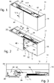
- Fig. 1 shows a furniture item 10 comprising a ceiling panel 12, two side panels 14, 16, a bottom 20 and back-panel 28 which delimit a compartment V.
- Two leaves 22, 24, horizontally sliding one with respect to and on the other, can cover ( Fig. 1 ) or uncover ( Fig. 2 ) the compartment V.
- Each leaf 22, 24 is supported in known manner by a pair of brackets 30, 32 connected to carriages provided with rollers sliding inside a rail 34, set e.g. on the ceiling panel 12.
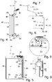
- the mechanism 40 ( fig. 4 ) comprises a pair of first arms 44, 54 hinged to the compartment V around a vertical axis X1 by means of two optional, e.g. angular, brackets 42, 52.
- the brackets 42, 52 allow the fine adjustment of the axes X1, X2 inside the compartment V.
- the arms 46, 56 and the arms 44, 54 are parallel to each other and straight.
- a second pair of parallel arms 46, 56 is hinged, respectively, to the first arms 44, 54 around a vertical axis X2, parallel to X1.
- a wheel 48, 58 At the end of arms 46, 56 is mounted a wheel 48, 58 with a pivoting axis X3 parallel to X1 and X2.
- the wheel 48, 58 can slide inside a complementary guide 70 mounted on the inner side of the leaf 24 ( Fig. 6 ); therefore, the leaf 24 can be moved relatively to the mechanism 40 without breaking away.
- the arms 44, 54 are connected by a bar 60, and/or the arms 46, 56 are connected by a bar 62.
- the arms 44, 54 and the arms 46, 56 may have on the side facing the other arm a groove or cavity in which to Insert the end of the bar.
- the mechanism 40 is configured approximately as in Fig. 7 , with the arms 44, 46, 54, 56 turned and directed towards the panel 12 ( FIG. 7 ).
- the boundary of guide 70 abuts on the wheel 48, 58. Then the rotation of the arms 46, 56 about the axis X1 and the rotation with respect to the arms 44, 54 about the axis X2 increases a lot. Eventually, the arms 44, 54 are approximately orthogonal to the plane of the leaves 22, 24 (or, which is the same, to the back-panel 28) and the arms 46, 56 are substantially orthogonal to the arms 44, 54 ( Fig. 8 ).
- the arms 44, 54 and the arms 46, 56 form at this point an L-shaped support, the outer segment of which is parallel to the plane of the leaves 22, 24 (and parallel to the sliding direction of the leaves 22, 24).
- the articulation with respect to axis X2 between the arms 44, 54 and the arms 46, 56 allows the mechanism 40 to deform and dynamically follow the movement of the leaf 24.
- the rotation of the arms 46, 56 with respect to the arms 44, 54 varies the position of the roller 48, 58 when the leaf 24 moves: the wheel 48, 58 can therefore assume two different positions relative to the open/closed position of the leaf 24. Not only one gains length in the stop limit of the open the leaf 24 (the arms 46, 56 may have any length), but the relative displacement (for e.g.
- the mechanism has other advantages. E.g. it has increased smoothness, because the arms 44, 46, 53, 56 rotate on and are hinged with pins having relatively small diameter, so the friction that these develop during their rotation is proportionally negligible compared to the length of the levers.
Landscapes
- Engineering & Computer Science (AREA)
- Mechanical Engineering (AREA)
- Hinges (AREA)
- Legs For Furniture In General (AREA)
- Cabinets, Racks, Or The Like Of Rigid Construction (AREA)
- Support Devices For Sliding Doors (AREA)
Description
- The invention relates to a mechanism for leaves, in particular to a motion system for sliding leaves, and to the furniture item comprising the mechanism.
- On some furniture item there are mounted sliding leaves to avoid the disadvantages of the hinged ones, i.e. less closing surfaces for a compartment and bulky opening radii. Each sliding leaf is supported by a pair of brackets connected to carriages with wheels sliding inside a rail, formed in a metal section, arranged on the ceiling and/or on the bottom of the furniture item.
- The brackets and the carriages are not sufficient to support and guide the leaf, and a movable arm, mounted inside the compartment that the leaf closes, is added.
- Such arm is extendable linearly, in a direction perpendicular to the leaf, to allow it to get out cantilevered with respect to the furniture item, and has L-shape with a wheel at one end. The L-shape serves to increase the horizontal stroke of the leaf, nonetheless a problem of these systems is that the horizontal stroke is limited by the end-stop imposed by the arm, so much that the compartment cannot be fully opened. Increasing the length of the L's transverse segment increases the opening stroke of the leaf, but the closing one is reduced. A compromise is chosen, however it is not satisfactory. To move the L-shaped arm, the latter also comprises a rack meshing on toothed wheels. The system is noisy and the movement has several friction caused by the meshing of the toothed wheels on the rack.
-
EP0864719 refers to a system for opening and closing doors relative to a compartment. A mechanism supports the door during a horizontal movement in order to uncover the compartment, and the the mechanism comprises a first arm and a second arm. - To obviate to at least one of these problems is the main object of the invention, which is defined in the appended claims, wherein the dependent ones define advantageous variants.
- It is therefore proposed a furniture item comprising the features of claim 1.
- In particular, the furniture item comprises a compartment, a sliding leaf to close/uncover the compartment, a mechanism mounted inside the compartment to support the leaf during a horizontal movement in order to uncover the compartment, wherein the mechanism comprises a first arm, which is mounted inside the compartment, for supporting the leaf during a horizontal movement in order to uncover the compartment, and hinged to the compartment about - in use - a first vertical axis, a second arm, which is adapted to be parallel to the sliding direction of the leaf when the leaf is moved to uncover the compartment, has the free end facing the opening direction of the leaf, and at said free end there is mounted a wheel with a pivoting axis parallel to the first and second axes, the wheel being able to slide inside a complementary guide mounted on the inner side of the leaf, wherein the arms are mounted so that the rotation of the second arm with respect to the first arm varies the position of the wheel when the leaf moves, the wheel thereby assuming two different positions relative to the open/closed position of the leaf, and at the end of the stroke of horizontal sliding for the leaf,the first arm is approximately orthogonal to the plane of the leaf and the second arm is substantially orthogonal to the first arm thereby forming at this point an L-shaped arm.
- Preferably the arms of each pair are equal to each other, for minimizing the number of required and stored parts.
- Preferably, to increase the strength, one or each pair of arms is connected by a bar or rigid, e.g. straight, member. Preferably, the arms comprise a slot or seat in which to insert one end of the bar or rigid element, or attachment means for the bar or the rigid element.
- Preferably, the first arms are hinged to the compartment or movable via an anchoring element, e.g. a bracket, e.g. angular. The anchoring element may comprise a base fixable to the furniture item or the compartment and
a portion adjustable in position with respect to the base. - The advantage is to adjust the position of the arms when they are mounted and/or coupled to the leaf.
- The advantages of the invention will be more apparent from the following description of a preferred embodiment, making reference the attached drawing in which
-
Fig. 1 shows a three dimensional view of a furniture item with closed leaves; -
Fig. 2 shows a three dimensional view of the furniture item ofFig. 1 with a leaf open; -
Fig. 3 shows the furniture item ofFIG. 2 seen from above; -
Fig. 4 shows isolated a support mechanism for the leaf; -
Fig. 5 shows a cross section according to the plane V-V ofFig. 1 ; -
Fig. 6 shows an enlargement of the hatched area C2 inFig. 5 ; -
Fig. 7 and 8 show schematically two configurations of the support mechanism. -
Fig. 9 shows an enlargement of the dotted circle C1 inFig. 3 . - In the figures, identical numbers indicate identical or conceptually alike parts, and the elements are described as being in use.
-
Fig. 1 shows afurniture item 10 comprising aceiling panel 12, twoside panels bottom 20 and back-panel 28 which delimit a compartment V. - Two
leaves Fig. 1 ) or uncover (Fig. 2 ) the compartment V. - Each
leaf brackets rail 34, set e.g. on theceiling panel 12. - For supporting and guiding a
leaf mechanism 40 mounted inside the compartment V. For simplicity, we will describe the mechanism only for theleaf 24, since the mechanism may be identical for theleaf 22. - The mechanism 40 (
fig. 4 ) comprises a pair offirst arms brackets brackets - Preferably, to simplify the kinematics and the construction, the
arms arms - A second pair of
parallel arms first arms - At the end of
arms wheel wheel complementary guide 70 mounted on the inner side of the leaf 24 (Fig. 6 ); therefore, theleaf 24 can be moved relatively to themechanism 40 without breaking away. - To give greater rigidity to the
mechanism 40, preferably thearms bar 60, and/or thearms bar 62. For example, thearms arms - To move the
leaf 24 and discover the compartment V, it is enough to just pull theleaf 24 towards the outside of thefurniture item 10. Theleaf 24, supported by thebracket 32 and themechanism 40, moves away from thefurniture item 10, arranging itself more outside than the closedleaf 22. One can then push theleaf 24 to overlap it to theleaf 22. - At rest, with the
leaf 24 closed (fig. 1 ), themechanism 40 is configured approximately as inFig. 7 , with thearms FIG. 7 ). - The detachment of the
leaf 24 from thefurniture item 10 makes thearms opposite panel 14. - Even during the horizontal sliding of
leaf 24 towards and above theleaf 22, thearms Fig. 7 and 8 ) about the axis X1. - At the end of the stroke of horizontal sliding, the boundary of
guide 70 abuts on thewheel arms arms arms leaves 22, 24 (or, which is the same, to the back-panel 28) and thearms arms 44, 54 (Fig. 8 ). - The
arms arms leaves 22, 24 (and parallel to the sliding direction of theleaves 22, 24). The articulation with respect to axis X2 between thearms arms mechanism 40 to deform and dynamically follow the movement of theleaf 24. In particular, the rotation of thearms arms roller leaf 24 moves: thewheel leaf 24. Not only one gains length in the stop limit of the open the leaf 24 (thearms arms arms arms 46, 56) moves along with theleaf 24. In fact, with the rigid L-shaped arm of the prior art the support point is fixed relatively to the sliding direction of the leaves and does not go over the opening of compartment V, for which the end-of-travel stop is inherently determined. - With the
arms wheel 58, 48 (i.e. the point of support for the leaf 24). Also, note that the rotation of thearms Fig. 9 ). Thus the stop limit ofleaf 24 widens and/or moves towards theleaf 22, thereby allowing to uncover more the compartment V. - The mechanism has other advantages. E.g. it has increased smoothness, because the
arms - It has higher rigidity, due to the fact that there are no relative plays as in the pinion-rack coupling of the prior art, and to the fact that torsion bars can be used (see. E.g. the
bars 60, 62) with very robust section. - Possible variants compared to those already described are e.g.:
- the number and form of the leaves;
- the use of upper carriages in the
guides 34 to move or support the leaves is optional but advantageous. Although themechanism 40 alone may be able to hold the leaf, in most applications it can only ensure that theleaf 24 remains vertically parallel to the structure of thefurniture item 10, or keeps aligned vertically the top and bottom of theleaf 24 by avoiding asymmetries and jams in thecarriages leaf 24 is guided by an upper carriage and a lower one; - the use of a pair of
arms arms arms arms - the use of a pair of arms hinged to each other is optional. It could suffice e.g. to have an L-shaped arm with the end hinged to the compartment. However to move the abovementioned support point for the leaf one may also implement other systems, e.g. hinged arms to the compartment around also or only to one or more axes orthogonal to the plane of the leaf (that is, perpendicular to the back-panel 28), electric actuators or drivers, o articulated parallelograms.
Claims (6)
- Furniture item (10) comprisinga compartment (V),a sliding leaf {22, 24) to close/uncover the compartment,a mechanism (40) mounted inside the compartment to support the leaf during a horizontal movement in order to uncover the compartment,wherein the mechanism comprisesa first arm (44, 54) which ismounted inside the compartment, for supporting the leaf during a horizontal movement in order to uncover the compartment, andhinged to the compartment about - in use - a first vertical axis (X1);a second arm (46, 56), whichis adapted to be parallel to the sliding direction of the leaf when the leaf is moved to uncover the compartment,has the free end facing the opening direction of the leaf, andat said free end there is mounted a wheel (48, 58) with a pivoting axis (X3) parallel to the first and second axes (X I , X2J,the wheel (48, 58) being able to slide inside a complementary guide (70) mounted on the inner side of the leaf (24),characterized in thatthe arms (44, 54) are mounted so thatthe rotation of the second arm (46, 56) with respect to the first arm {44, 54) varies the position of the wheel (48, 58} when the leaf (24) moves, the wheel (48, 58) thereby assuming two different positions relative to the open/closed position of the leaf (24), andat the end of the stroke of horizontal sliding for the leaf,the first arm is approximately orthogonal to the plane of the leaf (22, 24) andthe second arm (46, 56) is substantially orthogonal to the first arm {44, 54) thereby forming at this point an L-shaped arm.
- Furniture item (10) according to claim 1, wherein the first arm is hinged to the first arm (44, 54) around a second vertical axis (X2J, parallel to the first axis (X1).
- Furniture item (10) according to any one of the preceding claims, wherein the mechanism comprises a first pair of first parallel arms (44, 54) hinged to the compartment and a second pair of second parallel arms (46, 56) respectively hinged to the first arms.
- Furniture item (10) according to claim 1 or 2 or 3, wherein each pair of arms is connected by a rigid element (60, 62).
- Furniture item (10) according to claim 4, wherein each pair of arms comprises a seat in which to insert one end of the rigid element.
- Furniture item (10) according to claim 1 or 2 or 3 or 4 or 5, wherein the first pair of arms is hinged to the compartment or furniture item via an anchoring element (42, 52), the anchoring element comprisinga base fixable to the furniture item or compartment anda portion adjustable in position with respect to the base.
Priority Applications (1)
| Application Number | Priority Date | Filing Date | Title |
|---|---|---|---|
| SM20220196T SMT202200196T1 (en) | 2014-10-12 | 2015-09-10 | CABINET WITH DOOR SLIDING MECHANISM |
Applications Claiming Priority (2)
| Application Number | Priority Date | Filing Date | Title |
|---|---|---|---|
| ITTV20140146 | 2014-10-12 | ||
| PCT/IB2015/056944 WO2016059488A1 (en) | 2014-10-12 | 2015-09-10 | Furniture item with sliding leaf mechanism |
Publications (2)
| Publication Number | Publication Date |
|---|---|
| EP3204583A1 EP3204583A1 (en) | 2017-08-16 |
| EP3204583B1 true EP3204583B1 (en) | 2022-04-13 |
Family
ID=52101519
Family Applications (1)
| Application Number | Title | Priority Date | Filing Date |
|---|---|---|---|
| EP15778030.5A Active EP3204583B1 (en) | 2014-10-12 | 2015-09-10 | Furniture item with sliding leaf mechanism |
Country Status (11)
| Country | Link |
|---|---|
| US (1) | US10087667B2 (en) |
| EP (1) | EP3204583B1 (en) |
| JP (1) | JP6878272B2 (en) |
| CN (1) | CN106795730B (en) |
| BR (1) | BR112017006971B1 (en) |
| CA (1) | CA2963451C (en) |
| ES (1) | ES2912880T3 (en) |
| PL (1) | PL3204583T3 (en) |
| RU (1) | RU2694300C2 (en) |
| SM (1) | SMT202200196T1 (en) |
| WO (1) | WO2016059488A1 (en) |
Families Citing this family (8)
| Publication number | Priority date | Publication date | Assignee | Title |
|---|---|---|---|---|
| JP6527473B2 (en) * | 2016-01-18 | 2019-06-05 | 株式会社ハイレックスコーポレーション | Opening and closing mechanism |
| KR101674346B1 (en) * | 2016-03-31 | 2016-11-08 | 정용일 | A sliding device for a sliding door |
| IT201600104918A1 (en) * | 2016-10-19 | 2018-04-19 | Cinetto F Lli S R L | GUIDE DEVICE FOR FURNITURE DOORS |
| KR20180044589A (en) * | 2016-10-24 | 2018-05-03 | 엘지전자 주식회사 | Bathroom management apparatus |
| CN108343668B (en) * | 2017-01-23 | 2020-11-06 | 漳州灿坤实业有限公司 | Rotating shaft mechanism and cooking device with same |
| US20220213725A1 (en) * | 2019-03-27 | 2022-07-07 | Bortoluzzi Sistemi S.P.A. | Furniture item with a leaf |
| WO2021029120A1 (en) * | 2019-08-09 | 2021-02-18 | スガツネ工業株式会社 | Sliding door device |
| AT526423B1 (en) * | 2023-04-12 | 2024-03-15 | Kdm Innovation Gmbh | Arrangement with structure, cover element and guide system |
Family Cites Families (25)
| Publication number | Priority date | Publication date | Assignee | Title |
|---|---|---|---|---|
| GB1162415A (en) * | 1967-07-11 | 1969-08-27 | Miner Inc W H | Sliding Door Operating Mechanism |
| US5016318A (en) * | 1989-07-13 | 1991-05-21 | Panelfold, Inc. | Multi-directional radial wheel trolley and track for operable walls |
| DE19518499A1 (en) * | 1995-05-19 | 1996-11-21 | Matthias Reschreiter | Sliding door with several relatively slidable door leaves |
| ES2185895T3 (en) * | 1997-03-12 | 2003-05-01 | B & B Italia Spa | SYSTEM FOR OPENING AND CLOSING DOORS IN FURNITURE, ROOMS AND SIMILAR. |
| DE20003563U1 (en) * | 2000-02-26 | 2000-04-27 | Schüco International KG, 33609 Bielefeld | Sliding element unit |
| DE10200882A1 (en) * | 2002-01-11 | 2003-07-24 | Volkswagen Ag | Guide for moving flap on basic body such as container cover in vehicle consists of two arms, and slide rails |
| FR2846028A1 (en) * | 2002-10-17 | 2004-04-23 | Rotodor Ag | Door hinge articulation device for handicapped people, has carriage assembled in translational and rotational relationships with respect to guide and hinge, wheel located between carriage and side wall of guide |
| ITBL20030004A1 (en) * | 2003-04-09 | 2004-10-10 | Bortoluzzi Mobili S P A Ora Borto Luzzi Mobili S | SLIDING DOORS WITH CAM GUIDE FOR COPLANAR CLOSURE, |
| RU2263193C1 (en) * | 2004-07-09 | 2005-10-27 | Закрытое акционерное общество "Управляющая компания КМТ" (ЗАО "Управляющая компания КМТ") | Sliding door moving device |
| JP5523710B2 (en) * | 2005-11-29 | 2014-06-18 | ハルドア メカニズム プロダクション リミテッド | System for placing sliding doors |
| DE202008003694U1 (en) * | 2008-03-17 | 2009-08-06 | Dr. Hahn Gmbh & Co. Kg | Band for pivotally mounting a wing, a door, a window or the like. on a fixed frame |
| US8695165B2 (en) * | 2009-07-31 | 2014-04-15 | Rmd Industries Pty Ltd | Bogey assembly |
| CH702441A1 (en) * | 2009-12-18 | 2011-06-30 | Eku Ag | Drive arrangement with two guide rails for a sliding door. |
| RU2568866C2 (en) * | 2010-07-19 | 2015-11-20 | Хардур Топ Дизайн Энд Текнолоджи Лтд | System of puling out sliding door |
| DE202011002810U1 (en) * | 2011-02-16 | 2011-06-09 | Inter Ikea Systems B.V. | Mechanism for sliding door |
| DE202011002811U1 (en) | 2011-02-16 | 2011-04-21 | Unique Product & Design Co., Ltd., Yung Kang | Folding device for golf bag wagon |
| ITTV20110071A1 (en) * | 2011-05-23 | 2012-11-24 | Bortoluzzi Lab S R L | DEVICE FOR SLIDING DOORS WITH COMPLANAR CLOSING, PARTICULARLY FOR FURNITURE AND SIMILAR |
| ITTV20110070A1 (en) * | 2011-05-23 | 2012-11-24 | Bortoluzzi Lab S R L | DEVICE FOR SLIDING DOORS WITH COMPLANAR CLOSING, PARTICULARLY FOR FURNITURE AND SIMILAR |
| ITPN20120026A1 (en) * | 2012-05-29 | 2013-11-30 | Intechse Innovation & Technology Se Rvice Di Paolo | SUPPORT AND DRIVE DEVICE FOR SLIDING DOORS, IN PARTICULAR FOR CABINETS |
| KR101285257B1 (en) * | 2012-09-13 | 2013-07-11 | 주식회사 강탄산업 | Refrigerator having a combination open/close door |
| EP3913177B1 (en) * | 2012-12-05 | 2025-05-07 | Hawa Sliding Solutions AG | Device for connecting partition elements and functional unit |
| EP2851496A1 (en) * | 2013-09-18 | 2015-03-25 | Hawa Ag | Adjustable mounting device for a sliding element and sliding device |
| US20160066689A1 (en) * | 2014-09-09 | 2016-03-10 | TERNO SCORREVOLI s.r.I. | Device for the support and safe movement of cabinet doors |
| EP3088646B1 (en) * | 2015-04-27 | 2020-02-19 | Hawa Sliding Solutions AG | Guide device for a sliding door |
| EP3088645B1 (en) * | 2015-04-27 | 2018-06-27 | Hawa Sliding Solutions AG | Connection device for a sliding door |
-
2015
- 2015-09-10 PL PL15778030.5T patent/PL3204583T3/en unknown
- 2015-09-10 US US15/517,170 patent/US10087667B2/en active Active
- 2015-09-10 WO PCT/IB2015/056944 patent/WO2016059488A1/en not_active Ceased
- 2015-09-10 BR BR112017006971-7A patent/BR112017006971B1/en active IP Right Grant
- 2015-09-10 SM SM20220196T patent/SMT202200196T1/en unknown
- 2015-09-10 ES ES15778030T patent/ES2912880T3/en active Active
- 2015-09-10 JP JP2017516927A patent/JP6878272B2/en not_active Expired - Fee Related
- 2015-09-10 CA CA2963451A patent/CA2963451C/en active Active
- 2015-09-10 RU RU2017115440A patent/RU2694300C2/en active
- 2015-09-10 CN CN201580055180.6A patent/CN106795730B/en active Active
- 2015-09-10 EP EP15778030.5A patent/EP3204583B1/en active Active
Also Published As
| Publication number | Publication date |
|---|---|
| BR112017006971B1 (en) | 2022-08-16 |
| CA2963451A1 (en) | 2016-04-21 |
| RU2017115440A3 (en) | 2019-01-24 |
| BR112017006971A2 (en) | 2018-01-09 |
| CN106795730A (en) | 2017-05-31 |
| WO2016059488A1 (en) | 2016-04-21 |
| CA2963451C (en) | 2022-08-30 |
| JP2017534345A (en) | 2017-11-24 |
| US20170306676A1 (en) | 2017-10-26 |
| ES2912880T3 (en) | 2022-05-30 |
| RU2694300C2 (en) | 2019-07-11 |
| JP6878272B2 (en) | 2021-05-26 |
| RU2017115440A (en) | 2018-11-13 |
| EP3204583A1 (en) | 2017-08-16 |
| SMT202200196T1 (en) | 2022-07-21 |
| US10087667B2 (en) | 2018-10-02 |
| CN106795730B (en) | 2019-08-16 |
| PL3204583T3 (en) | 2022-08-08 |
Similar Documents
| Publication | Publication Date | Title |
|---|---|---|
| CA2963451C (en) | Furniture item with sliding leaf mechanism | |
| US8763205B2 (en) | Running gear arrangement having a guide rail for a sliding door | |
| US10000962B2 (en) | Guiding device for a sliding door | |
| EP1613831B1 (en) | Sliding doors with cam guides for coplanar closing, particularly for pieces of furniture or similars | |
| US20090007491A1 (en) | Pivotable Sliding Door | |
| EP2960411B1 (en) | Smoke ventilating roof window arrangement | |
| EP3159218A2 (en) | Pinch-protection sliding trim cover assembly for a vehicle sliding door | |
| CH660839A5 (en) | OPENING DEVICE FOR SLIDING DOORS ALIGNED WITH FURNITURE. | |
| EP2241706A1 (en) | A coplanar sliding wing door construction, particularly for wardrobes and the like | |
| CN109641510B (en) | Shading device for a glass pane of a motor vehicle | |
| CS207707B2 (en) | Window dropper | |
| US8894137B2 (en) | Open roof construction for a vehicle | |
| JP6974582B2 (en) | Open roof structure for vehicles | |
| CN111101791A (en) | Hinge and door and window assembly | |
| AU2009243840A1 (en) | Sectional door | |
| RU157834U1 (en) | DEVICE FOR OPENING AND CLOSING A SLIDING DOOR OF A VEHICLE | |
| EP0507993B1 (en) | A device capable of achieving opening and closing of a plurality of wing elements by combined swinging and sliding movements thereof | |
| CN109532705A (en) | For guiding preferably biparting swing-sliding-door cable guide device | |
| WO2007113655A2 (en) | Device for compensating for the tilt of a sliding wing and item of furniture comprising this device | |
| ITBO20130347A1 (en) | HANDLING DEVICE FOR DOORS OR WINDOWS WITH OPENING TO LEAF AND RIBALTA. | |
| EP2336471A1 (en) | Multi-leaf folding door | |
| CN205400344U (en) | Limit structure and install this limit structure's door | |
| TWI910768B (en) | A guide system for guiding at least one movably-supported door wing and furniture with the guide system | |
| CN120883008A (en) | Cooking appliances with specific guide sliders for retractable doors. | |
| HK40032479A (en) | Door body moving device |
Legal Events
| Date | Code | Title | Description |
|---|---|---|---|
| STAA | Information on the status of an ep patent application or granted ep patent |
Free format text: STATUS: THE INTERNATIONAL PUBLICATION HAS BEEN MADE |
|
| PUAI | Public reference made under article 153(3) epc to a published international application that has entered the european phase |
Free format text: ORIGINAL CODE: 0009012 |
|
| STAA | Information on the status of an ep patent application or granted ep patent |
Free format text: STATUS: REQUEST FOR EXAMINATION WAS MADE |
|
| 17P | Request for examination filed |
Effective date: 20170503 |
|
| AK | Designated contracting states |
Kind code of ref document: A1 Designated state(s): AL AT BE BG CH CY CZ DE DK EE ES FI FR GB GR HR HU IE IS IT LI LT LU LV MC MK MT NL NO PL PT RO RS SE SI SK SM TR |
|
| AX | Request for extension of the european patent |
Extension state: BA ME |
|
| DAV | Request for validation of the european patent (deleted) | ||
| DAX | Request for extension of the european patent (deleted) | ||
| GRAP | Despatch of communication of intention to grant a patent |
Free format text: ORIGINAL CODE: EPIDOSNIGR1 |
|
| STAA | Information on the status of an ep patent application or granted ep patent |
Free format text: STATUS: GRANT OF PATENT IS INTENDED |
|
| RIN1 | Information on inventor provided before grant (corrected) |
Inventor name: DAL CASTEL, RODOLFO Inventor name: GIROTTO, ADRIANO |
|
| INTG | Intention to grant announced |
Effective date: 20210519 |
|
| GRAS | Grant fee paid |
Free format text: ORIGINAL CODE: EPIDOSNIGR3 |
|
| GRAJ | Information related to disapproval of communication of intention to grant by the applicant or resumption of examination proceedings by the epo deleted |
Free format text: ORIGINAL CODE: EPIDOSDIGR1 |
|
| GRAL | Information related to payment of fee for publishing/printing deleted |
Free format text: ORIGINAL CODE: EPIDOSDIGR3 |
|
| STAA | Information on the status of an ep patent application or granted ep patent |
Free format text: STATUS: REQUEST FOR EXAMINATION WAS MADE |
|
| INTC | Intention to grant announced (deleted) | ||
| GRAP | Despatch of communication of intention to grant a patent |
Free format text: ORIGINAL CODE: EPIDOSNIGR1 |
|
| STAA | Information on the status of an ep patent application or granted ep patent |
Free format text: STATUS: GRANT OF PATENT IS INTENDED |
|
| INTG | Intention to grant announced |
Effective date: 20220128 |
|
| GRAA | (expected) grant |
Free format text: ORIGINAL CODE: 0009210 |
|
| STAA | Information on the status of an ep patent application or granted ep patent |
Free format text: STATUS: THE PATENT HAS BEEN GRANTED |
|
| AK | Designated contracting states |
Kind code of ref document: B1 Designated state(s): AL AT BE BG CH CY CZ DE DK EE ES FI FR GB GR HR HU IE IS IT LI LT LU LV MC MK MT NL NO PL PT RO RS SE SI SK SM TR |
|
| REG | Reference to a national code |
Ref country code: GB Ref legal event code: FG4D |
|
| REG | Reference to a national code |
Ref country code: CH Ref legal event code: EP |
|
| REG | Reference to a national code |
Ref country code: DE Ref legal event code: R096 Ref document number: 602015078223 Country of ref document: DE |
|
| REG | Reference to a national code |
Ref country code: IE Ref legal event code: FG4D |
|
| REG | Reference to a national code |
Ref country code: AT Ref legal event code: REF Ref document number: 1483541 Country of ref document: AT Kind code of ref document: T Effective date: 20220515 |
|
| REG | Reference to a national code |
Ref country code: ES Ref legal event code: FG2A Ref document number: 2912880 Country of ref document: ES Kind code of ref document: T3 Effective date: 20220530 |
|
| REG | Reference to a national code |
Ref country code: LT Ref legal event code: MG9D |
|
| REG | Reference to a national code |
Ref country code: NL Ref legal event code: MP Effective date: 20220413 |
|
| PG25 | Lapsed in a contracting state [announced via postgrant information from national office to epo] |
Ref country code: NL Free format text: LAPSE BECAUSE OF FAILURE TO SUBMIT A TRANSLATION OF THE DESCRIPTION OR TO PAY THE FEE WITHIN THE PRESCRIBED TIME-LIMIT Effective date: 20220413 |
|
| PG25 | Lapsed in a contracting state [announced via postgrant information from national office to epo] |
Ref country code: SE Free format text: LAPSE BECAUSE OF FAILURE TO SUBMIT A TRANSLATION OF THE DESCRIPTION OR TO PAY THE FEE WITHIN THE PRESCRIBED TIME-LIMIT Effective date: 20220413 Ref country code: PT Free format text: LAPSE BECAUSE OF FAILURE TO SUBMIT A TRANSLATION OF THE DESCRIPTION OR TO PAY THE FEE WITHIN THE PRESCRIBED TIME-LIMIT Effective date: 20220816 Ref country code: NO Free format text: LAPSE BECAUSE OF FAILURE TO SUBMIT A TRANSLATION OF THE DESCRIPTION OR TO PAY THE FEE WITHIN THE PRESCRIBED TIME-LIMIT Effective date: 20220713 Ref country code: LT Free format text: LAPSE BECAUSE OF FAILURE TO SUBMIT A TRANSLATION OF THE DESCRIPTION OR TO PAY THE FEE WITHIN THE PRESCRIBED TIME-LIMIT Effective date: 20220413 Ref country code: HR Free format text: LAPSE BECAUSE OF FAILURE TO SUBMIT A TRANSLATION OF THE DESCRIPTION OR TO PAY THE FEE WITHIN THE PRESCRIBED TIME-LIMIT Effective date: 20220413 Ref country code: GR Free format text: LAPSE BECAUSE OF FAILURE TO SUBMIT A TRANSLATION OF THE DESCRIPTION OR TO PAY THE FEE WITHIN THE PRESCRIBED TIME-LIMIT Effective date: 20220714 Ref country code: FI Free format text: LAPSE BECAUSE OF FAILURE TO SUBMIT A TRANSLATION OF THE DESCRIPTION OR TO PAY THE FEE WITHIN THE PRESCRIBED TIME-LIMIT Effective date: 20220413 Ref country code: BG Free format text: LAPSE BECAUSE OF FAILURE TO SUBMIT A TRANSLATION OF THE DESCRIPTION OR TO PAY THE FEE WITHIN THE PRESCRIBED TIME-LIMIT Effective date: 20220713 |
|
| PG25 | Lapsed in a contracting state [announced via postgrant information from national office to epo] |
Ref country code: RS Free format text: LAPSE BECAUSE OF FAILURE TO SUBMIT A TRANSLATION OF THE DESCRIPTION OR TO PAY THE FEE WITHIN THE PRESCRIBED TIME-LIMIT Effective date: 20220413 Ref country code: LV Free format text: LAPSE BECAUSE OF FAILURE TO SUBMIT A TRANSLATION OF THE DESCRIPTION OR TO PAY THE FEE WITHIN THE PRESCRIBED TIME-LIMIT Effective date: 20220413 Ref country code: IS Free format text: LAPSE BECAUSE OF FAILURE TO SUBMIT A TRANSLATION OF THE DESCRIPTION OR TO PAY THE FEE WITHIN THE PRESCRIBED TIME-LIMIT Effective date: 20220813 |
|
| REG | Reference to a national code |
Ref country code: DE Ref legal event code: R097 Ref document number: 602015078223 Country of ref document: DE |
|
| PG25 | Lapsed in a contracting state [announced via postgrant information from national office to epo] |
Ref country code: SK Free format text: LAPSE BECAUSE OF FAILURE TO SUBMIT A TRANSLATION OF THE DESCRIPTION OR TO PAY THE FEE WITHIN THE PRESCRIBED TIME-LIMIT Effective date: 20220413 Ref country code: RO Free format text: LAPSE BECAUSE OF FAILURE TO SUBMIT A TRANSLATION OF THE DESCRIPTION OR TO PAY THE FEE WITHIN THE PRESCRIBED TIME-LIMIT Effective date: 20220413 Ref country code: EE Free format text: LAPSE BECAUSE OF FAILURE TO SUBMIT A TRANSLATION OF THE DESCRIPTION OR TO PAY THE FEE WITHIN THE PRESCRIBED TIME-LIMIT Effective date: 20220413 Ref country code: DK Free format text: LAPSE BECAUSE OF FAILURE TO SUBMIT A TRANSLATION OF THE DESCRIPTION OR TO PAY THE FEE WITHIN THE PRESCRIBED TIME-LIMIT Effective date: 20220413 Ref country code: CZ Free format text: LAPSE BECAUSE OF FAILURE TO SUBMIT A TRANSLATION OF THE DESCRIPTION OR TO PAY THE FEE WITHIN THE PRESCRIBED TIME-LIMIT Effective date: 20220413 |
|
| PLBE | No opposition filed within time limit |
Free format text: ORIGINAL CODE: 0009261 |
|
| STAA | Information on the status of an ep patent application or granted ep patent |
Free format text: STATUS: NO OPPOSITION FILED WITHIN TIME LIMIT |
|
| 26N | No opposition filed |
Effective date: 20230116 |
|
| PG25 | Lapsed in a contracting state [announced via postgrant information from national office to epo] |
Ref country code: AL Free format text: LAPSE BECAUSE OF FAILURE TO SUBMIT A TRANSLATION OF THE DESCRIPTION OR TO PAY THE FEE WITHIN THE PRESCRIBED TIME-LIMIT Effective date: 20220413 |
|
| PG25 | Lapsed in a contracting state [announced via postgrant information from national office to epo] |
Ref country code: MC Free format text: LAPSE BECAUSE OF FAILURE TO SUBMIT A TRANSLATION OF THE DESCRIPTION OR TO PAY THE FEE WITHIN THE PRESCRIBED TIME-LIMIT Effective date: 20220413 |
|
| REG | Reference to a national code |
Ref country code: BE Ref legal event code: MM Effective date: 20220930 |
|
| PG25 | Lapsed in a contracting state [announced via postgrant information from national office to epo] |
Ref country code: SI Free format text: LAPSE BECAUSE OF FAILURE TO SUBMIT A TRANSLATION OF THE DESCRIPTION OR TO PAY THE FEE WITHIN THE PRESCRIBED TIME-LIMIT Effective date: 20220413 |
|
| P01 | Opt-out of the competence of the unified patent court (upc) registered |
Effective date: 20230515 |
|
| PG25 | Lapsed in a contracting state [announced via postgrant information from national office to epo] |
Ref country code: LU Free format text: LAPSE BECAUSE OF NON-PAYMENT OF DUE FEES Effective date: 20220910 |
|
| PG25 | Lapsed in a contracting state [announced via postgrant information from national office to epo] |
Ref country code: IE Free format text: LAPSE BECAUSE OF NON-PAYMENT OF DUE FEES Effective date: 20220910 |
|
| PG25 | Lapsed in a contracting state [announced via postgrant information from national office to epo] |
Ref country code: BE Free format text: LAPSE BECAUSE OF NON-PAYMENT OF DUE FEES Effective date: 20220930 |
|
| PG25 | Lapsed in a contracting state [announced via postgrant information from national office to epo] |
Ref country code: HU Free format text: LAPSE BECAUSE OF FAILURE TO SUBMIT A TRANSLATION OF THE DESCRIPTION OR TO PAY THE FEE WITHIN THE PRESCRIBED TIME-LIMIT; INVALID AB INITIO Effective date: 20150910 |
|
| PG25 | Lapsed in a contracting state [announced via postgrant information from national office to epo] |
Ref country code: CY Free format text: LAPSE BECAUSE OF FAILURE TO SUBMIT A TRANSLATION OF THE DESCRIPTION OR TO PAY THE FEE WITHIN THE PRESCRIBED TIME-LIMIT Effective date: 20220413 |
|
| PG25 | Lapsed in a contracting state [announced via postgrant information from national office to epo] |
Ref country code: MK Free format text: LAPSE BECAUSE OF FAILURE TO SUBMIT A TRANSLATION OF THE DESCRIPTION OR TO PAY THE FEE WITHIN THE PRESCRIBED TIME-LIMIT Effective date: 20220413 |
|
| PG25 | Lapsed in a contracting state [announced via postgrant information from national office to epo] |
Ref country code: MT Free format text: LAPSE BECAUSE OF FAILURE TO SUBMIT A TRANSLATION OF THE DESCRIPTION OR TO PAY THE FEE WITHIN THE PRESCRIBED TIME-LIMIT Effective date: 20220413 |
|
| PGFP | Annual fee paid to national office [announced via postgrant information from national office to epo] |
Ref country code: DE Payment date: 20240820 Year of fee payment: 10 |
|
| PGFP | Annual fee paid to national office [announced via postgrant information from national office to epo] |
Ref country code: GB Payment date: 20240820 Year of fee payment: 10 Ref country code: SM Payment date: 20240821 Year of fee payment: 10 |
|
| PGFP | Annual fee paid to national office [announced via postgrant information from national office to epo] |
Ref country code: FR Payment date: 20240820 Year of fee payment: 10 |
|
| PGFP | Annual fee paid to national office [announced via postgrant information from national office to epo] |
Ref country code: AT Payment date: 20240821 Year of fee payment: 10 |
|
| PGFP | Annual fee paid to national office [announced via postgrant information from national office to epo] |
Ref country code: PL Payment date: 20240820 Year of fee payment: 10 |
|
| PG25 | Lapsed in a contracting state [announced via postgrant information from national office to epo] |
Ref country code: BG Free format text: LAPSE BECAUSE OF FAILURE TO SUBMIT A TRANSLATION OF THE DESCRIPTION OR TO PAY THE FEE WITHIN THE PRESCRIBED TIME-LIMIT Effective date: 20220413 |
|
| PG25 | Lapsed in a contracting state [announced via postgrant information from national office to epo] |
Ref country code: BG Free format text: LAPSE BECAUSE OF FAILURE TO SUBMIT A TRANSLATION OF THE DESCRIPTION OR TO PAY THE FEE WITHIN THE PRESCRIBED TIME-LIMIT Effective date: 20220413 |
|
| REG | Reference to a national code |
Ref country code: AT Ref legal event code: UEP Ref document number: 1483541 Country of ref document: AT Kind code of ref document: T Effective date: 20220413 |
|
| PGFP | Annual fee paid to national office [announced via postgrant information from national office to epo] |
Ref country code: ES Payment date: 20241001 Year of fee payment: 10 |
|
| PGFP | Annual fee paid to national office [announced via postgrant information from national office to epo] |
Ref country code: CH Payment date: 20241001 Year of fee payment: 10 |
|
| PGFP | Annual fee paid to national office [announced via postgrant information from national office to epo] |
Ref country code: TR Payment date: 20250903 Year of fee payment: 11 Ref country code: IT Payment date: 20250820 Year of fee payment: 11 |
|
| REG | Reference to a national code |
Ref country code: CH Ref legal event code: H13 Free format text: ST27 STATUS EVENT CODE: U-0-0-H10-H13 (AS PROVIDED BY THE NATIONAL OFFICE) Effective date: 20260504 |