EP3204561B1 - Fill valve - Google Patents
Fill valve Download PDFInfo
- Publication number
- EP3204561B1 EP3204561B1 EP15775448.2A EP15775448A EP3204561B1 EP 3204561 B1 EP3204561 B1 EP 3204561B1 EP 15775448 A EP15775448 A EP 15775448A EP 3204561 B1 EP3204561 B1 EP 3204561B1
- Authority
- EP
- European Patent Office
- Prior art keywords
- flow
- membrane
- opening
- fill valve
- valve according
- Prior art date
- Legal status (The legal status is an assumption and is not a legal conclusion. Google has not performed a legal analysis and makes no representation as to the accuracy of the status listed.)
- Active
Links
Images


Classifications
-
- E—FIXED CONSTRUCTIONS
- E03—WATER SUPPLY; SEWERAGE
- E03D—WATER-CLOSETS OR URINALS WITH FLUSHING DEVICES; FLUSHING VALVES THEREFOR
- E03D1/00—Water flushing devices with cisterns ; Setting up a range of flushing devices or water-closets; Combinations of several flushing devices
- E03D1/30—Valves for high or low level cisterns; Their arrangement ; Flushing mechanisms in the cistern, optionally with provisions for a pre-or a post- flushing and for cutting off the flushing mechanism in case of leakage
- E03D1/32—Arrangement of inlet valves
-
- F—MECHANICAL ENGINEERING; LIGHTING; HEATING; WEAPONS; BLASTING
- F16—ENGINEERING ELEMENTS AND UNITS; GENERAL MEASURES FOR PRODUCING AND MAINTAINING EFFECTIVE FUNCTIONING OF MACHINES OR INSTALLATIONS; THERMAL INSULATION IN GENERAL
- F16K—VALVES; TAPS; COCKS; ACTUATING-FLOATS; DEVICES FOR VENTING OR AERATING
- F16K31/00—Actuating devices; Operating means; Releasing devices
- F16K31/12—Actuating devices; Operating means; Releasing devices actuated by fluid
- F16K31/18—Actuating devices; Operating means; Releasing devices actuated by fluid actuated by a float
- F16K31/34—Actuating devices; Operating means; Releasing devices actuated by fluid actuated by a float acting on pilot valve controlling the cut-off apparatus
-
- F—MECHANICAL ENGINEERING; LIGHTING; HEATING; WEAPONS; BLASTING
- F16—ENGINEERING ELEMENTS AND UNITS; GENERAL MEASURES FOR PRODUCING AND MAINTAINING EFFECTIVE FUNCTIONING OF MACHINES OR INSTALLATIONS; THERMAL INSULATION IN GENERAL
- F16K—VALVES; TAPS; COCKS; ACTUATING-FLOATS; DEVICES FOR VENTING OR AERATING
- F16K47/00—Means in valves for absorbing fluid energy
- F16K47/02—Means in valves for absorbing fluid energy for preventing water-hammer or noise
-
- G—PHYSICS
- G05—CONTROLLING; REGULATING
- G05D—SYSTEMS FOR CONTROLLING OR REGULATING NON-ELECTRIC VARIABLES
- G05D7/00—Control of flow
- G05D7/01—Control of flow without auxiliary power
- G05D7/0106—Control of flow without auxiliary power the sensing element being a flexible member, e.g. bellows, diaphragm, capsule
- G05D7/012—Control of flow without auxiliary power the sensing element being a flexible member, e.g. bellows, diaphragm, capsule the sensing element being deformable and acting as a valve
Description
Die Erfindung betrifft ein Füllventil zum Befüllen eines Spülkastens mit einer Flüssigkeit, insbesondere mit Wasser, wobei das Füllventil einen Zulauf mit einer einen Durchflussregler aufweisenden Drosselvorrichtung zur Druckverminderung der in Strömungsrichtung einströmenden Flüssigkeit aufweist.The invention relates to a filling valve for filling a cistern with a liquid, in particular with water, wherein the filling valve has an inlet with a flow regulator having a throttle device for reducing the pressure of the liquid flowing in the direction of flow.
Ein Problem bei derartigen Füllventilen ist, dass das Einströmen der Flüssigkeit durch die Drosselvorrichtung in das Füllventil mit einer leicht als störend empfundenen Geräuschentwicklung verbunden ist.A problem with such filling valves is that the inflow of liquid through the throttle device is connected to the filling valve with a slightly annoying perceived noise.
Ein gattungsgemäßes, komplex aufgebautes Füllventil mit Durchflussregler wird in der
Eine Aufgabe der Erfindung ist, ein gattungsgemäßes Füllventil bereitzustellen, bei dem die Strömungsgeräusche beim Befüllen weiter reduziert sind.An object of the invention is to provide a generic filling valve in which the flow noise during filling are further reduced.
Die gestellte Aufgabe wird erfindungsgemäß durch die Merkmale des Anspruches 1 gelöst. Vorteilhafte Weiterbildungen werden in den Unteransprüchen beschrieben. Erfindungsgemäß ist der Durchflussregler als Volumenstromregelung zum Erhalt einer Volumenstromkonstanz in Abhängigkeit von dem Fließdruck der Flüssigkeit am Zulauf ausgebildet, um Strömungsgeräusche beim befüllen des Spülkastens zu reduzieren, wobei die Volumenstromregelung einen sich über den Strömungsquerschnitt des Zulaufs erstreckenden Träger mit zumindest einer Primäröffnung aufweist, die mittels einer vorgeschalteten Membran mit Erhöhung des Fließdruckes fortschreitend dichtend überdeckbar bzw. mit Erniedrigung derselben fortschreitend freigebbar angeordnet ist, wobei die Volumenstromregelung mindestens eine Sekundäröffnung aufweist, die permanent geöffnet ausgebildet ist, wodurch gewährleistet ist, dass ein Teil der Flüssigkeit die Volumenstromregelung auch im Falle einer vollständig abdichtenden Überdeckung der zumindest einen Primäröffnung so lange durchströmt, wie der Fließdruck der Flüssigkeit an der zumindest einen Sekundäröffnung größer Null ist, wobei die zumindest eine Sekundäröffnung von einer Innenwandung begrenzt wird, die zur Reduktion von Schallemission beim Durchfluss aufgeraut und/oder gedimpelt ausgebildet ist.The stated object is achieved by the features of
Die Geräuschentwicklung beim Befüllen des Wasserkastens durch das Füllventil hängt unter anderem von dem Volumenstrom sowie von dessen Änderungen ab. Es ist beim Befüllen des Wasserkastens üblicherweise eine starke Abhängigkeit des Volumenstroms und damit der Füllzeit von dem anliegenden Fließdruck zu beobachten. Ferner ändert sich die Geräuschentwicklung mit der Änderung des Volumenstromes. Abgesehen davon, dass sich mit Erhöhung des Volumenstromes auch dessen Fließgeräusche verstärken, können auch allgemein, da Änderungen stärker ins Bewusstsein dringen, Änderungen der Geräuschentwicklung leicht als entsprechend störend empfunden werden. Je geringer die Abweichungen der Volumenstromkonstanz bei sich änderndem Fließdruck sind, desto geringer ist die als störend empfundene Geräuschentwicklung. Bei bekannten Drosseln steigt der Volumenstrom mit Vergrößerung des Drucks an. Bei der erfindungsgemäßen Drossel hingegen treten infolge der Volumenstromkonstanz auch bei höherem Drücken keine erhöhten Fließgeräusche auf.The noise when filling the water box through the filling valve depends, among other things, on the volume flow and its changes. When filling the water box, it is usual to observe a strong dependence of the volume flow and thus of the filling time on the applied flow pressure. Furthermore, the noise changes with the change in the volume flow. Apart from the fact that amplify its flow noise with increasing the volume flow, and in general, as changes penetrate more consciously, changes in the noise can be easily perceived as corresponding disturbing. The smaller the deviations in the volume flow constancy are as the flow pressure changes, the lower the noise development perceived as disturbing. In known chokes, the volume flow increases with increasing pressure. In the case of the throttle according to the invention, on the other hand, owing to the constant volume flow, no increased flow noise occurs even at higher pressures.
Die Volumenstromkonstanz kann jeweils so aufgefasst werden, dass der Volumenstrom in etwa konstant bleibt und somit Abweichungen nach oben und/oder nach unten aufweisen kann. Diese Abweichungen können in einem Rahmen von bis zu ±25%, vorzugsweise von bis zu ±15% und idealerweise von wenigen Prozentpunkten, wie bis zu ±10%, eines Mittelwerts liegen. Der Fließdruck, auch dynamischer bzw. hydrodynamischer Druck genannt, ergibt sich aus der Differenz des Gesamtdruckes und des Druckverlustes infolge eines Strömens der Flüssigkeit in einer Leitung.The volume flow constancy can be understood in each case so that the volume flow remains approximately constant and thus may have deviations upwards and / or downwards. These deviations may be within a range of up to ± 25%, preferably up to ± 15%, and ideally of a few percentage points, such as up to ± 10% of an average. The flow pressure, also called dynamic or hydrodynamic pressure, results from the difference between the total pressure and the pressure loss due to a flow of the liquid in a line.
Erfindungsgemäß ist vorgesehen, dass die Volumenstromregelung einen sich über den Strömungsquerschnitt des Zulaufs erstreckenden Träger mit zumindest einer Primäröffnung aufweist. Die Primäröffnung kann in Abhängigkeit des Fließdruckes bzw. des Gesamtdrucks der Flüssigkeit mit Erhöhung des Drucks fortschreitend dichtend überdeckbar bzw. mit Erniedrigung desselben fortschreitend freigebbar angeordnet sein. Der Strömungsquerschnitt der Primäröffnung kann kleiner als der des Zuflusses ausgebildet sein, welches im Sinne einer Drossel eine Druckminderung der Flüssigkeit an der Primäröffnung hervorruft. Vorzugsweise ist zur Volumenstromregelung der Primäröffnung eine Membran vorgeschaltet. Sie ist in Strömungsrichtung vor der Primäröffnung angeordnet. Diese Konstruktion mit Träger ermöglicht eine einfache Konstruktion der Volumenstromregelung.According to the invention, provision is made for the volumetric flow control to have a support with at least one primary opening extending over the flow cross-section of the inlet. The primary opening can depend on the flow pressure or the Total pressure of the liquid with increasing pressure progressively sealing overcoverable or be arranged with a reduction thereof progressively releasable. The flow cross-section of the primary opening may be smaller than that of the inflow formed, which causes a pressure reduction of the liquid at the primary opening in the sense of a throttle. Preferably, a membrane is connected upstream of the volume flow control of the primary opening. It is arranged upstream of the primary opening in the flow direction. This construction with carrier allows a simple construction of the flow control.
Vorteilhaft einfach kann der Träger einstückig beispielsweise als Spritzgussteil, insbesondere als Kunststoffspritzgussteil ausgebildet sein.Advantageously simple, the carrier can be integrally formed, for example, as an injection molded part, in particular as a plastic injection molded part.
Wird der Fließdruck eingangsseitig erhöht, so erfolgt eine fortschreitende Überdeckung der Primäröffnung, welches eine Verminderung des strömungswirksamen Strömungsquerschnittes der Primäröffnung und damit eine Erhöhung der Fließgeschwindigkeit der Flüssigkeit an den Primäröffnungen und zugleich eine weitere Druckminderung in der Flüssigkeit bewirkt. Diese Überdeckung kann vorteilhaft dichtend erfolgen. Wird das Füllventil geschlossen, so findet ein Druckausgleich zwischen den Räumen in Strömungsrichtung vor und hinter der Primäröffnung statt, wodurch dieselbe wieder freigegeben wird. Hierzu kann die Überdeckung zur Überdeckung der Primäröffnung in Strömungsrichtung durch den Druck unter Aufbau einer Rückstellkraft gegen die Primäröffnung geführt werden. Mit dem Druckausgleich kann die Überdeckung unter Abbau der Rückstellkraft in ihre Ausgangsposition zurückgebracht, insbesondere zurückgeführt werden. Es kann die vom Fließdruck abhängige Regelung des Volumenstromes automatisch und selbst geregelt erfolgen.If the flow pressure increases on the input side, there is a progressive overlap of the primary opening, which causes a reduction of the flow effective flow cross section of the primary opening and thus an increase in the flow velocity of the liquid at the primary openings and at the same time a further pressure reduction in the liquid. This overlap can be done advantageously sealing. If the filling valve is closed, a pressure equalization takes place between the spaces in the flow direction in front of and behind the primary opening, whereby the same is released again. For this purpose, the overlap to cover the primary opening in the flow direction can be performed by the pressure under construction of a restoring force against the primary opening. With the pressure compensation, the cover can be returned to its original position by reducing the restoring force, in particular be returned. It can be done automatically and self-regulated by the flow pressure-dependent control of the flow.
Die Membran kann flexibel ausgebildet sein. Vorteilhaft wegen einer leichten Biegsamkeit und Flexibilität kann die Membran unbelastet als Scheibe, insbesondere als Kreisscheibe ausgebildet sein. Sie kann einstückig beispielsweise aus einem Butadien-Kautschuk gefertigt sein.The membrane can be designed to be flexible. Advantageous because of a slight flexibility and flexibility, the membrane can be designed unloaded as a disk, in particular as a circular disk. It may be made in one piece, for example, from a butadiene rubber.
Es kann in einer Weiterbildung des Füllventils vorgesehen sein, dass die Membran unter Erhöhung des Fließdrucks der Flüssigkeit in eine Dichtungsposition hinein dichtend gegen die Primäröffnung führbar ist. Wird der Flüssigkeitsstrom in Strömungsrichtung hinter der Membran dem Durchflussregler abgesperrt, so findet hinter der Membran ein Druckausgleich mit dem Druck vor der Membran statt, wodurch die Membran flexibel wieder in eine Offenposition, in der der Fließdruck gleich oder etwa gleich Null ist, zurück schwingen kann.It may be provided in a development of the filling valve that the membrane can be guided by increasing the flow pressure of the liquid into a sealing position in a sealing manner against the primary opening. If the liquid flow in the direction of flow behind the membrane is shut off from the flow regulator, a pressure equalization takes place behind the membrane with the pressure in front of the membrane, whereby the membrane can flexibly swing back into an open position in which the flow pressure is equal to or about zero ,
In einer vorteilhaften Ausführungsform des Füllventils kann die Membran so in der Volumenstromregelung angeordnet sein, dass sie über die Regelung des Durchflusses unter steigendem Fließdruck in eine definierte gebogene oder gekrümmte Form gebracht werden. Diese Formdefinition der Membran kann durch konstruktive Maßnahmen erfolgen, mittels derer ein für die Dichtungsposition vorgesehener Ausnahmeraum für die Membran begrenzt wird. Über die definierte Form der Membran in der Dichtungsposition bzw. auf dem Verformungsweg in die Dichtungsposition hinein und die Werkstoffwahl kann das Regelverhalten der Membran entschieden beeinflusst werden.In an advantageous embodiment of the filling valve, the membrane can be arranged in the flow control that they are brought by regulating the flow under increasing flow pressure in a defined curved or curved shape. This shape definition of the membrane can be carried out by design measures, by means of which an intended for the sealing position exception space for the membrane is limited. On the defined shape of the membrane in the sealing position or on the deformation path in the sealing position and the choice of material, the control behavior of the membrane can be decisively influenced.
Die gebogene oder gekrümmte Form der Membran kann so ausgebildet sein, dass sie einen gekrümmten Raum, insbesondere einen einzigen gekrümmten Raum begrenzt. Insbesondere kann sie auf eine sphärische Form oder annähernd sphärische Form gebracht werden. Annähernd heißt, dass die Form auch Abflachungen und andere Änderungen hinsichtlich ihrer sphärischen Krümmung aufweisen kann.The curved or curved shape of the membrane may be formed so as to define a curved space, in particular a single curved space. In particular, it can be brought to a spherical shape or approximately spherical shape. It roughly means that the shape can also have flattening and other changes in its spherical curvature.
Die Abflachung kann sich durch ein definiertes Abstützen der Membran an dem Stützkörper ausbilden. Hierzu kann der Abstützköper vorzugsweise radial innen zur Membran eine Abstützfläche aufweisen.The flattening can be formed by a defined supporting the membrane on the support body. For this purpose, the Abstützköper preferably radially inward to the membrane have a support surface.
Die Distanzkörper können in einer Weiterbildung des Füllventils unter Ausbildung eines Zwischenraumes radial zu der Abstützfläche beabstandet angeordnet sein. Damit so kann sich die Membran unter weiterer Verspannung zwischen Abstützfläche und Distanzköper in den Zwischenraum zu den Primäröffnungen hin durchbiegen. Hierbei kann die Durchbiegung unter Ausbildung einer Wulst, insbesondere ringartigen Wulst erfolgen. Insbesondere kann die Membran kann in der Dichtungsposition bezüglich einer radialenaxialen Schnittebene ein W-förmiges Profil aufweisen. Die Abstützung der Membran kann bereits auf dem Wege von der Offenposition in die Dichtungsposition hinein oder in der Dichtungsposition auftreten.The spacers may be arranged radially spaced from each other in a development of the filling valve to form a gap radially to the support surface. Thus, the membrane can bend under further tension between the support surface and Distanzköper in the space to the primary openings out. In this case, the deflection can take place to form a bead, in particular ring-like bead. In particular, the membrane may have a W-shaped profile in the sealing position with respect to a radial axial sectional plane. The support of the membrane can already occur on the way from the open position into the sealing position or in the sealing position.
Von der Kräftesymmetrie her günstig, kann die gekrümmte räumliche Form der Membran die oder etwa die einer vorzugsweise im Zenit abgeflachten Hohlellipsoidkalotte sein. Dieser Ellipsoid kann als Grundfläche eine Ellipse oder, als Sonderfall der Ellipse, einen Kreis aufweisen. Etwa die Form bedeutet, dass sie von dieser eher mathematischen Form, insbesondere in der Art der Abflachung, definiert abweichen kann, wobei hierüber eine weitere Verspannung der Membran erzielt werden kann.Favorable from the force symmetry, the curved spatial shape of the membrane may be that of a hollow ellipsoidal dome preferably flattened at the zenith. This ellipsoid can have an ellipse as base area or, as a special case of the ellipse, a circle. About the shape means that it can deviate from this rather mathematical form, in particular in the nature of the flattening, with this over a further strain of the membrane can be achieved.
Infolge der elastischen Verformung der Membran in die definierte gebogene oder gekrümmte Form kann die Membran definiert verspannt werden, wodurch sie einer weiteren Verformung, wie einem Geräusch erzeugenden Schwingen, einen definierten Verformungswiderstand entgegensetzt. Diese räumliche Verformung zur definierten gekrümmten Form bewirkt somit ein stabileres Regelverhalten, indem das Schwingen der Membran, für welches sie in ihrer flachen, d.h. ungekrümmten Form neigt, vermieden werden kann. Dieses Schwingen macht sich in bestimmten Druckbereichen dadurch bemerkbar, dass der Regler den Volumenstrom stärker als erforderlich drosselt und die Flüssigkeit abgebremst wird, um dann den Flüssigkeitsstrom unmittelbar wieder weniger zu drosseln und die Flüssigkeit wieder stärker zu beschleunigen. Dieses Verhalten bewirkt ein Schwingen innerhalb des gesamten Leitungssystems des Füllventils und damit eine entsprechende Geräuschemission. Besonders effektiv ist die Geräuschverminderung in den kritischen Bereichen der Volumenstromregelung, in denen die Änderung des Volumenstroms besonders groß ist und damit das Auftreten von Schwingungen entsprechend besonders stark ist. Dieser kritische Bereich ist insbesondere zu beobachten, wenn der Volumenstrom durch partielle Schließung der ersten Öffnungen bereits stark vermindert ist.Due to the elastic deformation of the membrane into the defined curved or curved shape, the membrane can be clamped in a defined manner, whereby it opposes a further deformation, such as a noise-generating swing, a defined deformation resistance. This spatial deformation to the defined curved shape thus causes a more stable control behavior, by the swinging of the membrane, for which it tends in its flat, ie non-curved shape, can be avoided. This swinging is noticeable in certain pressure ranges in that the controller restricts the volume flow more than necessary and the liquid is slowed down, in order then to reduce the flow of liquid immediately less and to accelerate the liquid again more strongly. This behavior causes a swing within the entire pipe system of the filling valve and thus a corresponding noise emission. Especially effective is the noise reduction in the critical areas of the flow control, in which the change in the flow rate is particularly large and thus the occurrence of vibrations is particularly strong. This critical area can be observed in particular if the volume flow is already greatly reduced by partially closing the first openings.
In einer vorteilhaften Weiterbildung des Füllventils kann vorgesehen sein, dass die Membran in der Offenposition flach ausgebildet ist. Sie kann einen flachen Körper aufweisen. Diese Form hat den Vorteil, dass die Membran bereits bei geringen Strömungsgeschwindigkeiten beginnen kann, sich räumlich verformen. Die Membran kann in der Offenposition parallel zum Öffnungsquerschnitt der ersten Öffnung angeordnet sein. Insbesondere kann sich die Membran mit Vergrößerung des Fließdrucks zu der ersten Öffnung hin sphärischen auswölben und zur weiteren Abdichtung der ersten Öffnung vorzugsweise im Zenit ihrer gekrümmten Form an dem Stützkörper zur Anlage kommen. Die Membran kann in der Dichtungsposition eine im Zenit abgeflachte sphärische Form, insbesondere eine im Zenit abgeflachte Hohlkugelkalotte oder Hohlellipsoidkalotte ausbilden. In einer anderen Ausführungsform des Füllventils kann die Membran bereits in der Offenposition gekrümmt, insbesondere sphärisch ausgebildet sein. Sie kann so angeordnet sein, dass sie sich in der Offenposition bereits in Fließrichtung zu dem Träger und zwar zur ersten Öffnung hin wölbt und dass sie dann, wie oben beschrieben, hier jedoch unter Verstärkung der Krümmung, in die definierte gekrümmte Form in die Dichtungsposition hinein gebracht wird. Zu ihrer Halterung und Positionierung kann die Membran in der Offenposition der Volumenstromregelung in Strömungsrichtung vor und in einem zur Strömungsrichtung axialen Abstand zu der Primäröffnung gehalten angeordnet sein. Zur axialen Beabstandung kann mindestens ein Distanzkörper vorgesehen sein, an dem sich die Membran axial abstützt. In einer Schließposition der Volumenstrombegrenzung kann die Membran insbesondere unter Ausbildung der oben beschriebenen gekrümmten, insbesondere der sphärischen Form in Strömungsrichtung dichtend an der Primäröffnung anliegend angeordnet sein. Bereits auf dem Weg der Membran zu ihrer dichtenden Anlage an den Primäröffnungen hin, kann eine Verminderung des strömungswirksamen Strömungsquerschnitts und damit eine Drosselung des Drucks und Erhöhung der Fließgeschwindigkeit erfolgen.In an advantageous embodiment of the filling valve can be provided that the membrane is formed flat in the open position. It can have a flat body. This form has the advantage that the membrane can begin even at low flow velocities, deform spatially. The membrane may be arranged in the open position parallel to the opening cross section of the first opening. In particular, the diaphragm may bulge outwardly as the flow pressure increases toward the first opening and, for the purpose of further sealing the first opening, preferably come into contact with the support body at the zenith of its curved shape. The membrane can form in the sealing position a flattened in zenith spherical shape, in particular a flattened in zenith Hohlkugelkalotte or Hohlellipsoidkalotte. In another embodiment of the filling valve, the membrane may already be curved in the open position, in particular be formed spherical. It can be arranged so that it already bulges in the open position in the direction of flow to the carrier and indeed to the first opening and that then, as described above, but here to reinforce the Curvature is brought into the defined curved shape in the sealing position inside. For its mounting and positioning, the membrane may be arranged in the open position of the volume flow control in the flow direction before and in an axial distance to the flow direction to the primary opening. For axial spacing, at least one spacer can be provided, on which the membrane is axially supported. In a closed position of the volume flow limitation, the membrane may be arranged in the flow direction sealingly against the primary opening, in particular forming the above-described curved, in particular the spherical shape. Already on the way of the membrane towards its sealing contact with the primary openings, a reduction of the flow-effective flow cross-section and thus a throttling of the pressure and increasing the flow velocity can take place.
In einer vorteilhaften Weiterbildung des Füllventils kann die Membran zumindest in Strömungsrichtung lose bleibend an dem zumindest einem Distanzkörper anliegen.In an advantageous development of the filling valve, the membrane can abut against the at least one spacer body, at least in the direction of flow, in a manner that remains loose.
Konstruktiv einfach können der zumindest eine Distanzkörper oder die mehreren Distanzkörper insgesamt eine ringartige, insbesondere kreisringartige, gegen Strömungsrichtung weisende Anlagefläche für die Membran bilden. Hierbei kann der zumindest eine Distanzkörper eine Ringform aufweisen. Diese kann zum Druckausgleich mit radialen Durchgangsöffnungen und/oder Schlitzen versehen sein.Constructively simple, the at least one spacer or the plurality of spacers can form a ring-like, in particular annular, facing the flow direction bearing surface for the membrane. Here, the at least one spacer can have a ring shape. This can be provided for pressure equalization with radial passage openings and / or slots.
Sind mehrere Distanzkörper vorgesehen, so können diese jeweils gleich oder sogar identisch aufgebaut sein. Sie können in einer Kreisform angeordnet sein. Insbesondere können sie bezüglich einer Mittelachse des Trägers auf einem Umfangkreis und vorzugsweise umfänglich gleich beabstandet zueinander angeordnet sind. Damit können sie in ihrer Gesamtheit eine über den Umfang unterbrochene Ringform und eine entsprechend unterbrochene Anlagefläche für die Membran bilden. In beiden Fällen kann die Ringform koaxial zu einer vorgesehenen Mittelachse der Volumenstromregelung angeordnet sein. Vorzugsweise fallen Mittelachse des Trägers und die der Volumenstromregelung zusammen.If a plurality of spacers are provided, they may each be the same or even identical. They can be arranged in a circular shape. In particular, they may be arranged with respect to a central axis of the carrier on a circumferential circle and preferably circumferentially equally spaced from one another. Thus, they can in their entirety a broken across the circumference ring shape and form a correspondingly discontinued contact surface for the membrane. In both cases, the ring shape can be arranged coaxially to a planned center axis of the flow control. Preferably, center axis of the carrier and the volume flow control coincide.
Ferner kann die Membran so zu der Ringform angeordnet sein, dass sie sich, vorzugsweise permanent, an der Ringform mit einem radial äußeren umfänglichen Bereich abstützt und mit bei Einsetzen des Durchflusses von Flüssigkeit durch die Volumenstromregelung, vorzugsweise ab einem bestimmten Fließdruck, unter weiterer Abstützung an der Ringform beginnt, sich zu dem Träger, d.h. zu der ersten Öffnung hin vorzugsweise sphärisch zu wölben.Further, the membrane can be arranged to the annular shape that it is supported, preferably permanently, on the annular shape with a radially outer circumferential region and with onset of the flow of liquid through the flow control, preferably from a certain flow pressure, with further support the ring shape begins to become the carrier, ie preferably bulging toward the first opening.
In einer vorteilhaften Weiterbildung des Füllventils kann die Anlagefläche, zur definierten Abstützung und leichteren Wölbung der anliegenden Membran, in Strömungsrichtung radial nach Innen abgeschrägt ausgebildet sein. Insbesondere kann die Anlagefläche mit einer Komponente radial nach Innen weisen. Die Anlagefläche kann eine Flächennormale mit einer gegen Strömungsrichtung weisenden Komponente aufweisen. Die Anlagefläche kann einen radial äußeren zweiten Abschnitt zur Abstützung der Membran im unbelasteten Zustand aufweisen, dessen Flächennormale gegen Strömungsrichtung weist. Die Anlagefläche ist vorzugsweise ungekrümmt ausgebildet. Die schräggestellter Anlagefläche erleichtert die Verformung der Membran in die gekrümmte räumliche Form hinein. Die schräggestellter Anlagefläche kann zugleich als Begrenzungsfläche dienen, die die gekrümmte räumliche Form der Membran von außen her definiert.In an advantageous embodiment of the filling valve, the contact surface, for defined support and easier curvature of the adjacent membrane, be formed in the flow direction radially tapered inwards. In particular, the contact surface with a component can point radially inwards. The contact surface may have a surface normal with a component facing the flow direction. The contact surface may have a radially outer second portion for supporting the membrane in the unloaded state, the surface normal facing the flow direction. The contact surface is preferably formed without bending. The inclined contact surface facilitates the deformation of the membrane into the curved spatial shape. The inclined contact surface can also serve as a boundary surface, which defines the curved spatial shape of the membrane from the outside.
In einer vorteilhaft einfachen Weiterbildung des Füllventils können die Distanzkörper als sich von dem Träger gegen Strömungsrichtung weg erstreckende Vorsprünge ausgebildet sein. Diese können eine zylindrische Form aufweisen. Sie können mit der Anlagefläche die Form eines schräg abgeschnittenen Zylinders, insbesondere Kreiszylinders, aufweisen. Hierbei kann der oben beschriebene radial äußere zweite Abschnitt eine Restfläche der gegen Strömungsrichtung weisenden Stirnseite des Zylinders sein.In an advantageous simple development of the filling valve, the spacers may be formed as protruding from the carrier towards the flow direction extending projections. These can have a cylindrical shape. You can use the contact surface the shape of an oblique cut cylinder, in particular circular cylinder have. In this case, the above-described radially outer second section may be a residual surface of the end face of the cylinder facing the direction of flow.
Insbesondere kann die Membran im Idealfall in der Dichtungsposition zu einem rotationssymmetrischen Körper gebogen ausgebildet sein.In particular, the membrane may ideally be bent in the sealing position to a rotationally symmetrical body.
In einer Weiterbildung des Füllventils können die Vorsprünge bezüglich einer Mittelachse auf einem Radius angeordnet sein. Es können die bezüglich der Mittelachse einander gegenüberliegenden Vorsprünge eine gleiche Höhe aufweisen. Hierzu können alle Vorsprünge eine gleiche Höhe aufweisen.In a development of the filling valve, the projections may be arranged with respect to a central axis on a radius. It may have the same with respect to the central axis projections opposite an equal height. For this purpose, all projections may have an equal height.
Es können aber auch umfänglich benachbarte Vorsprünge eine unterschiedliche Höhe und einander gegenüberliegenden Vorsprünge eine gleiche Höhe aufweisen. Sind hierbei beispielsweise insgesamt vier Vorsprünge vorgesehen, so verändert sich das Biegeverhalten der Membran gegenüber dem bei vier gleichen Vorsprüngen. Die Membran wird zunächst an den höheren Vorsprüngen bezüglich einer ersten radialen Biegeachse senkrecht zu einer die höheren Vorsprünge verbindenden Geraden etwa rinnenartig gebogen. Mit weiterer Erhöhung des Strömungsdrucks senkt sich die Membran auf die kleineren Vorsprünge ab, um an diesen zusätzlich um eine zweite Biegeachse, vorzugsweise senkrecht zur ersten Biegeachse räumlich gebogen zu werden. Hierbei kann davon ausgegangen werden, dass die Biegung um die erste Biegeachse leichter als die um die zweite Biegeachse ist. Mittels dieser Maßnahme mit den unterschiedlichen Höhen benachbarter Vorsprüngen kann eine stärkere Verspannung der Membran in der Dichtungsposition erzielt werden. Gemäß eigenen Versuchen kann durch die Maßnahme eine verbesserte Geräuschreduzierung erzielt werden.However, circumferentially adjacent protrusions may also have a different height and opposing protrusions having the same height. If in this case, for example, a total of four projections are provided, the bending behavior of the membrane changes compared to that of four identical projections. The membrane is first bent approximately channel-like at the higher projections with respect to a first radial bending axis perpendicular to a straight line connecting the higher projections. With a further increase in the flow pressure, the membrane is lowered onto the smaller projections in order to be additionally spatially bent on them by a second bending axis, preferably perpendicular to the first bending axis. It can be assumed that the bending around the first bending axis is easier than that around the second bending axis. By means of this measure with the different heights of adjacent projections, a stronger clamping of the membrane in the sealing position can be achieved. According to our own experiments, the measure allows an improved noise reduction to be achieved.
Die Membran kann senkrecht zur Strömungsrichtung radial verschiebungsfest und vorzugsweise axial relativ bewegbar, insbesondere verschieblich, mittig mit dem Träger verbunden sein. Hierzu kann die Membran mittig eine Stecköffnung aufweisen, in die zur Ausbildung einer Steckverbindung ein an dem Träger mittig vorgesehener, sich gegen Strömungsrichtung erstreckender Steckvorsprung eingreift. Vorzugsweise ist die Steifigkeit der Membran so hoch, dass sie selbsttragend ist.The membrane can be radial perpendicular to the flow direction non-displaceable and preferably axially relatively movable, in particular displaceable, be centrally connected to the carrier. For this purpose, the membrane may centrally have a plug-in opening, in which engages the formation of a plug connection to the carrier centrally provided, extending against the flow direction plug projection. Preferably, the stiffness of the membrane is so high that it is self-supporting.
Es können in einer Weiterbildung des Füllventils zumindest zwei Primäröffnungen, vorzugsweise zumindest vier Primäröffnungen vorgesehen sein. Diese können bezüglich einer Mitte vorzugsweise auf einem ersten Radius und vorzugsweise umfänglich gleich beabstandet angeordnet sein. Die Mitte kann bezüglich der symmetrischen Anordnung der Primäröffnungen durch eine Drehsymmetrieachse parallel zur Strömungsrichtung gekennzeichnet sein. Die Primäröffnungen können gleiche Öffnungsquerschnitte aufweisen.In a development of the filling valve, at least two primary openings, preferably at least four primary openings, can be provided. These may preferably be equidistantly spaced with respect to a center at a first radius and preferably circumferentially. The center can be characterized with respect to the symmetrical arrangement of the primary openings by a rotational symmetry axis parallel to the flow direction. The primary openings may have the same opening cross-sections.
Zur Einstellung eines bestimmten Abstandes und damit der Kraft bzw. des Fließdrucks kann der Träger einen sich gegen Strömungsrichtung erstreckenden und radial außen zur Primäröffnung angeordneten Distanzkörper aufweisen, an dem die Membran in Strömungsrichtig vorzugsweise lose bleibend axial anliegt. Von der Statik günstig kann pro Primäröffnung mindestens ein Distanzkörper oder können pro Primäröffnung zwei Distanzkörper vorgesehen sein. Die Distanzkörper können in einem radial äußeren Bereich axial an der Membran angreifend angeordnet sein. Über die axiale Größe und/oder radiale Anordnung, d.h. Beabstandung von der Mittelachse der Distanzkörper sowie beispielsweise über die Flexibilität der Membran kann der Fließdruckbereich eingestellt werden. Dieser Fließdruckbereich kann eine untere Grenze, an der die Membran beginnt, von den Distanzkörpern gehalten sich in Strömungsrichtung gegen die Primäröffnungen durchzubiegen, und die obere Grenze aufweisen, an der die Membran die Primäröffnungen vollständig abdeckt.To set a certain distance and thus the force or the flow pressure, the carrier may have a counter-flow direction and radially outside the primary opening arranged spacer body on which the membrane in flow properly preferably remains loosely axially. From statics favorable per primary opening at least one spacer or can be provided per primary opening two spacers. The spacers may be arranged to engage axially in a radially outer region engaging the membrane. About the axial size and / or radial arrangement, ie spacing from the central axis of the spacers and, for example, on the flexibility of the membrane, the flow pressure range can be adjusted. This flow pressure region may have a lower limit at which the membrane begins to be deflected by the spacers in the direction of flow against the primary openings, and the upper limit at which the membrane may flow Completely covering primary openings.
Das Füllventil weißt als Teil der Volumenstromregelung mindestens eine Sekundäröffnung auf Diese ist permanent geöffnet ausgebildet. D.h. die Sekundäröffnung wird nicht wie die Primäröffnung überdeckt, sondern ist im Normalbetrieb freigehalten. Die Sekundäröffnung kann am Träger und hier vorzugsweise radial beabstandet zu den Primäröffnungen angeordnet sein. Es ist somit vorgesehen, dass ein Teil der Flüssigkeit praktisch als "Grundlast" die Volumenstromregelung solange durchströmt, wie der Fließdruck der Flüssigkeit an der Sekundäröffnung größer Null ist. Diese Grundlast bleibt auch dann erhalten, wenn die Primäröffnungen vollständig dichtend überdeckt sind. Somit kann auch bei höheren Fließdrücken ein nahezu linearer Volumenstromverlauf in Abhängigkeit von dem Fließdruck und somit zumindest ein nahezu konstanter Volumenstrom durch das Füllventil erfolgen. Der Volumenstrom kann beispielsweise 0,1 l/s betragen. Eine mögliche Schwankungsbreite des Volumenstromes kann weniger als +/-20% betragen. Die zumindest eine Sekundäröffnung und/oder die zumindest eine Primäröffnung sind jeweils von einer Innenwandung begrenzt, die zur Reduktion von Schallemission beim Durchfluss vorzugsweise gleichmäßig mit konstanter Rautiefe aufgeraut ausgebildet ist. Durch diese Maßnahme konnte bei dem Durchflussregler eine starke Reduzierung der Schallemission erzielt werden. Ursache hierfür kann sein, dass die aufgeraute Oberfläche eine Erhöhung der Mikroturbulenzen zu der Innenwandung der Sekundäröffnungen bewirken. Ebenfalls zur Reduktion der Schallemission können zumindest die in Strömungsrichtung unmittelbar an die Öffnungen anschließenden Flächen des Trägers mit der aufgerauten Oberfläche versehen sein.As part of the volume flow control, the filling valve has at least one secondary opening. This is permanently open. That is, the secondary opening is not covered as the primary opening, but is kept free in normal operation. The secondary opening can be arranged on the carrier and here preferably radially spaced from the primary openings. It is thus provided that a portion of the liquid practically flows through the volume flow control as a "base load" as long as the flow pressure of the liquid at the secondary opening is greater than zero. This base load is maintained even if the primary openings are completely covered by sealing. Thus, even at higher flow pressures, a nearly linear volume flow profile as a function of the flow pressure and thus at least a nearly constant volume flow through the filling valve can take place. The volume flow can be for example 0.1 l / s. A possible fluctuation range of the volume flow may be less than +/- 20%. The at least one secondary opening and / or the at least one primary opening are each bounded by an inner wall, which is preferably roughened with a constant roughness depth to reduce acoustic emission during the flow. As a result of this measure, it was possible to achieve a considerable reduction in the noise emission in the flow regulator. The reason for this may be that the roughened surface causes an increase in the microturbulences to the inner wall of the secondary openings. Also for the reduction of the acoustic emission, at least those in the flow direction directly to the openings be provided subsequent surfaces of the carrier with the roughened surface.
Die Aufrauhung kann eine Oberflächenstruktur in Form von Querrillen quer zur Strömungsrichtung aufweisen. Bevorzugt wegen erhöhter Geräuschminderung ist eine Struktur mit Längsrillen. Die aufgeraute Oberfläche kann auch eine isotrope Struktur aufweisen. Die Aufrauhung der Oberfläche kann beispielsweise durch Bürstung derselben hergestellt sein.The roughening can have a surface structure in the form of transverse grooves transversely to the flow direction. Preferred for increased noise reduction is a structure with longitudinal grooves. The roughened surface may also have an isotropic structure. The roughening of the surface can be produced, for example, by brushing it.
Anstatt oder zusätzlich zu der Aufrauhung können die Oberflächen gedimpelt ausgebildet sein. Sie können somit von einer Vielzahl vorzugsweise gleich beabstandeten Dimples überzogen sein. Die Dimples können ähnlich wie bei einem üblichen Golfball ausgebildet sein. Sie können als kleine flache Mulden mit kugelkalottenartigem Innenraum ausgebildet sein. Durch die gedimpelte Oberfläche kann die Zone der laminaren und damit geräuschsarmen Strömung der Flüssigkeit zu der Wandung hin vergrößert werden.Instead of or in addition to the roughening, the surfaces may be formed dimpled. They may thus be coated by a plurality of preferably equally spaced dimples. The dimples may be similar to a conventional golf ball. They may be formed as small shallow wells with kugelkalottenartigem interior. Due to the dimpled surface, the zone of the laminar and therefore low-noise flow of the liquid towards the wall can be increased.
Es können mindestens zwei Sekundäröffnungen, vorzugsweise mindestens acht Sekundäröffnungen vorgesehen sein. Die Sekundäröffnungen können bezüglich einer Mittelachse parallel zur Strömungsrichtung vorzugsweise auf einem zweiten Radius und vorzugsweise umfänglich gleich beabstandet voneinander angeordnet sein. Die Sekundäröffnungen können gleiche Öffnungsquerschnitte aufweisen. Durch diese permanent geöffnete Sekundäröffnung kann sichergestellt werden, dass auch bei hohen Fließdrücken, die einen zum Überdecken und damit Verschließen der Primäröffnungen notwendigen Fließdruck überschreiten, eine gleichmäßige Befüllung des Wasserkasten erfolgen kann. Die symmetrische Anordnung der Sekundäröffnung begünstigt ein laminares Strömungsverhalten des Volumenstromes, welches wiederum zur Geräuschminimierung beiträgt.At least two secondary openings, preferably at least eight secondary openings, can be provided. The secondary openings may be arranged with respect to a central axis parallel to the flow direction preferably at a second radius and preferably circumferentially equidistant from each other. The secondary openings may have the same opening cross-sections. By means of this permanently opened secondary opening, it can be ensured that a uniform filling of the water box can take place even at high flow pressures which exceed a flow pressure necessary for covering and thus closing the primary openings. The symmetrical arrangement of the secondary opening favors a laminar flow behavior of the volume flow, which in turn contributes to noise minimization.
Vorzugsweise ist der Träger zur Mittelachse als Drehsymmetrieachse rotationssymmetrisch ausgebildet. Die Primäröffnungen können radial innen zu den Sekundäröffnungen angeordnet sein. Es kann der erste Radius kleiner als der zweite Radius sein. Vorzugsweise sind die Sekundäröffnungen radial außen an dem Träger angeordnet. Der zweite Radius kann gleich dem Außenradius des Trägers sein. Damit kann die Flüssigkeit nahe oder unmittelbar an einer Innenwandung des Zulaufs und/oder Ablaufs entlang durch die Sekundäröffnungen strömen. Damit kann ein laminares Fließverhalten der Flüssigkeit an der Innenwandung erzielt werden, welches wiederum zur Geräuschminimierung beiträgt.Preferably, the carrier is rotationally symmetrical to the central axis as rotational symmetry axis. The Primary openings can be arranged radially inward to the secondary openings. It may be the first radius smaller than the second radius. Preferably, the secondary openings are arranged radially on the outside of the carrier. The second radius may be equal to the outer radius of the carrier. Thus, the liquid can flow near or immediately on an inner wall of the inlet and / or outlet along the secondary openings. Thus, a laminar flow behavior of the liquid can be achieved on the inner wall, which in turn contributes to noise minimization.
Die Distanzstücke können auf einem dritten Radius angeordnet sein. Der dritte Radius kann größer als der erste Radius und kleiner als der zweite Radius sein.The spacers may be arranged on a third radius. The third radius may be larger than the first radius and smaller than the second radius.
Die oben beschriebene "Grundlast" kann beispielsweise über die Anzahl der Sekundäröffnungen und deren Öffnungsquerschnitten voreingestellt werden. Bei einer Ausbildungsform des Füllventils kann die Summe der Öffnungsquerschnitte der Primäröffnungen größer als die Summe der Öffnungsquerschnitte der Sekundäröffnungen sein. Der Strömungsquerschnitt der Sekundäröffnung bzw. aller Sekundäröffnungen kann weniger als 40%, vorzugsweise weniger als 20% oder idealerweise um 10% als der Strömungsquerschnitt der Primäröffnung bzw. aller Primäröffnungen betragen. Vorzugsweise ist der Öffnungsquerschnitt jeder einzelnen Primäröffnung größer als der Öffnungsquerschnitt jeder einzelnen Sekundäröffnung.The "basic load" described above can be preset, for example, via the number of secondary openings and their opening cross-sections. In one embodiment of the filling valve, the sum of the opening cross sections of the primary openings may be greater than the sum of the opening cross sections of the secondary openings. The flow cross-section of the secondary opening or all secondary openings may be less than 40%, preferably less than 20% or ideally 10% as the flow cross-section of the primary opening or all primary openings. The opening cross section of each individual primary opening is preferably larger than the opening cross section of each individual secondary opening.
Es kann auch mindestens eine Tertiäröffnung vorgesehen sein, deren Öffnungsquerschnitt kleiner als der jeder der Primäröffnungen und größer als der jeder der Sekundäröffnungen ist. Diese können unabhängig von der Überdeckung der Primäröffnungen vorzugsweise dichtend überdeckbar sein. Die Überdeckung der Tertiäröffnungen kann somit so ausgelegt sein, dass vor Vollendung oder nach der Überdeckung der Primäröffnungen begonnen wird, die Tertiäröffnungen zu überdecken. Damit kann die Konstanz des Volumenstromes in Abhängigkeit vom Fließdruck der Flüssigkeit weiter verbessert und somit die Geräuschentwicklung insgesamt weiter minimiert werden.It is also possible to provide at least one tertiary opening whose opening cross section is smaller than that of each of the primary openings and larger than that of each of the secondary openings. These may preferably be sealingly coverable, regardless of the coverage of the primary openings. The covering of the tertiary openings can thus be designed so that the primary openings are started before the completion or after the covering Cover tertiary openings. Thus, the constancy of the volume flow in dependence on the flow pressure of the liquid can be further improved and thus the noise development can be further minimized.
Somit kann der Anteil des Flüssigkeitsstromes durch die geöffneten Primäröffnungen größer als der durch die Sekundäröffnungen sein. Damit wird ein anfänglicher hoher Volumenstrom sichergestellt.Thus, the proportion of the liquid flow through the opened primary openings can be greater than that through the secondary openings. This ensures an initial high volume flow.
Bei einer üblichen Drosselvorrichtung steigt der Volumenstrom oder Durchfluss nicht linear kontinuierlich an. Die Volumenstromregelung bei dem erfindungsgemäßen Füllventil kann zusammenfassend darauf fußen, dass der Durchfluss, im Vergleich zu einer üblichen Drosselvorrichtung, in einem unteren Druckbereich durch die Drosselvorrichtung höher ist, aber dass, sobald der Druck erhöht wird, durch die fortschreitende Überdeckung der Primäröffnungen kontinuierlich herab geregelt wird. Sind Sekundäröffnungen vorgesehen, so erfolgt der Durchfluss nach Überdeckung der Primäröffnungen allein durch die Sekundäröffnungen. Ist die Summe der Eröffnungsquerschnitte der Sekundäröffnungen wesentlich kleiner als die der Primäröffnungen, so kann in erster Näherung davon ausgegangen werden, dass der Durchfluss, da er durch die Sekundäröffnungen klein ist und sich somit mit weiterer Erhöhung des Drucks nur gering erhöht, bei Druckerhöhung im Wesentlichen konstant bleibt.In a conventional throttle device, the volume flow or flow does not increase linearly continuously. The volumetric flow control in the filling valve according to the invention can be summarized in that the flow is higher in a lower pressure range by the throttle device compared to a conventional throttle device, but that as the pressure is increased, continuously controlled by the progressive coverage of the primary openings becomes. If secondary openings are provided, the flow takes place after covering the primary openings solely through the secondary openings. If the sum of the opening cross sections of the secondary openings is substantially smaller than that of the primary openings, it can be assumed in a first approximation that the flow, since it is small due to the secondary openings and thus increases only slightly with a further increase in pressure, essentially increases when the pressure increases remains constant.
Über die Größe der Membran kann eingestellt werden, ob alle bzw. welche der Primäröffnungen in der Schließposition überdeckt werden. Es können auch Primäröffnungen unüberdeckt bleiben, die dann als Sekundäröffnungen fungieren.On the size of the membrane can be adjusted whether all or which of the primary openings are covered in the closed position. It can also remain uncovered primary openings, which then act as secondary openings.
Die Primäröffnungen können alternativ rasterförmig angeordnet oder als Maschen eines Siebes ausgebildet sein. Kraftmechanisch und strömungstechnisch günstig kann der Träger bezüglich einer Drehsymmetrieachse parallel zur Strömungsrichtung einen achsensymmetrischen Aufbau aufweisen. Die Drehsymmetrieachse kann gleich der Mittelachse des Trägers sein. Somit können die ersten und, soweit vorhanden, auch die Sekundäröffnungen über Drehung an der Drehsymmetrieachse in Deckung gebracht werden. Diese Symmetrieform wird auch Radiärsymmetrie genannt.The primary openings may alternatively be arranged in the form of a grid or formed as meshes of a sieve. In terms of force mechanics and flow technology, the carrier can have an axially symmetrical structure with respect to a rotational symmetry axis parallel to the flow direction. The rotational symmetry axis may be equal to the center axis of the carrier. Thus, the first and, if present, the secondary openings can be brought into coincidence by rotation on the rotational axis of symmetry. This symmetry form is also called radial symmetry.
Die vorliegende Erfindung wird im Folgenden anhand mehrerer in einer Zeichnung dargestellten Ausführungsformen der Führung näher erläutert. In der Zeichnung zeigen:
- Fig. 1
- eine Seitenansicht mit Teilschnitten einer Ausführungsform eines Füllventils mit Drosselvorrichtung und Durchflussregler,
- Fig. 2
- eine Detailvergrößerung gemäß dem Ausschnitt II mit einer ersten Ausführungsform des Durchflussreglers,
- Fig. 3
- eine Draufsicht auf den
Durchflussregler gemäß Figur 2 in einer Einzeldarstellung,Die Figuren 2 und 3 zeigen keine Ausführungsbeispiele, die im Schutzumfang der Ansprüche fallen. - Fig. 4
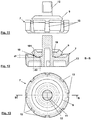
- eine Detailvergrößerung etwa gemäß dem Ausschnitt II mit einer Ausführungsform des Durchflussreglers gemäß der Erfindung,
- Fig. 5
- eine Draufsicht auf den
Durchflussregler gemäß Figur 4 in einer Einzeldarstellung, Figuren 6 und 7- jeweils eine perspektivische Einzeldarstellung eines Trägers einer weiteren Ausführungsform des Durchflussreglers ohne bzw. mit unverformter Membran,
- Fig. 6a
- eine
Detailvergrößerung aus Figur 6 , - Figuren 8-10
- jeweils eine weitere Ansicht des Trägers gemäß
Figur 7 mit Membran und - Figuren 10-14
- jeweils eine Ansicht des Trägers einer weiteren Ausführungsform des Durchflussreglers, jedoch mit verformten Membran.
- Fig. 1
- a side view with partial sections of an embodiment of a filling valve with throttle device and flow regulator,
- Fig. 2
- an enlarged detail according to the section II with a first embodiment of the flow controller,
- Fig. 3
- a plan view of the flow regulator according to
FIG. 2 in a single presentation, TheFIGS. 2 and 3 do not show embodiments falling within the scope of the claims. - Fig. 4
- an enlarged detail approximately according to the section II with an embodiment of the flow controller according to the invention,
- Fig. 5
- a plan view of the flow regulator according to
FIG. 4 in a single presentation, - FIGS. 6 and 7
- each a perspective individual representation of a carrier of another embodiment of the flow regulator without or with undeformed membrane,
- Fig. 6a
- an enlarged detail
FIG. 6 . - Figures 8-10
- in each case a further view of the carrier according to
FIG. 7 with membrane and - Figures 10-14
- in each case a view of the carrier of another embodiment of the flow regulator, but with a deformed membrane.
In
Der Durchflussregler 3 ist erfindungsgemäß als Volumenstromregelung 6 ausgebildet und ermöglicht eine Volumenstromkonstanz der Flüssigkeit in Abhängigkeit von dem Fließdruck der Flüssigkeit an dem Zulauf 2. Hierbei sind in den
Die Volumenstromregelung 6 ist in dem Zulauf 2 angeordnet. Dieser hat einen kreisförmigen Querschnitt. Die Volumenstromregelung 6 weist einen sich über den Strömungsquerschnitt des Zulaufs 2 erstreckenden Träger 7 auf. Der Träger 7 weist in den hier gezeigten beiden Ausführungsformen des Durchflussreglers 3 vier Primäröffnungen 8 auf, die in Abhängigkeit des Fließdrucks der Flüssigkeit am Zulauf 2 mit Erhöhung desselben fortschreitend dichtend überdeckbar bzw. mit Erniedrigung desselben fortschreitend freigebbar angeordnet sind. Damit kann mit Erhöhung des Fließdrucks der Flüssigkeit ein strömungswirksamer Strömungsquerschnitt an den Primäröffnungen 8 kontinuierlich verringert werden, bis er mit dichtender Überdeckung der Primäröffnungen 8 gleich Null wird.The
Der Träger 7 ist bezüglich einer mittigen Drehsymmetrieachse d parallel zur Strömungsrichtung s rotationssymmetrisch ausgebildet. Die Drehsymmetrieachse d ist gleich einer Mittelachse m. Die Primäröffnungen 8 sind bezüglich der Mittelachse m der Volumenstromregelung 6 auf einem ersten Radius r1 und umfänglich gleich beanstandet angeordnet. Sie weisen jeweils einen gleichen Öffnungsquerschnitt auf und sind, entsprechend der Rotationssymmetrie durch Drehung an der Drehsymmetrieachse deckungsgleich übereinander bringbar. Zur Überdeckung der Primäröffnung 8 ist eine Membran 9 vorgesehen, die in Strömungsrichtung s vor den Primäröffnungen 8 angeordnet ist. Die Membran 9 ist in einer in den Figuren gezeigten Offenposition der Volumenstromregelung 6, in der der Fließdruck gleich Null ist, in einem zur Strömungsrichtung s axialen Abstand a gehalten angeordnet. In einer hier nicht dargestellten aber leicht aus den Figuren ableitbaren Schließposition der Volumenstromregelung 6 liegt die Membran 9 dichtend an den Primäröffnungen 8 an. Zur Beabstandung der Membran 9 sind Distanzkörper, hier in Form von Vorsprüngen 10 vorgesehen, die sich gegen Strömungsrichtung s vom Träger 7 weg erstrecken und radial außen zu den Primäröffnungen 8 angeordnet sind. Die Membran 9 liegt in Strömungsrichtung axial an den Vorsprüngen 10 an. Zur sicheren Halterung sind radial außen pro Primäröffnung 8 zwei Vorsprünge 10 vorgesehen.The
Die Membran 9 ist in beiden Ausführungsformen der Volumenstromregelung 6 als ringförmige Kreisscheibe mit mittiger Stecköffnung 11 ausgebildet, die, senkrecht zur Strömungsrichtung s axial verschieblich und unter elastischer Aufweitung an ihrer Stecköffnung 11 in Strömungsrichtung s auf einen sich vom Träger 7 weg erstreckenden Steckvorsprung 12 aufgeschoben, festgelegt ist. Die Membran 9 weist eine Steifigkeit auf, die hoch genug ist, selbsttragend zu sein, und gering genug ist, um die geforderte Flexibilität zum Verbiegen der Membran 9 zu den Primäröffnungen 8 hin und Verdecken derselben zu gewährleisten.The
In der Ausführungsform gemäß den
Die Sekundäröffnungen 13 sind auf einem Umfangskreis mit einem zweiten Radius r2 angeordnet, der größer als der Umfangkreis mit erstem Radius r1 ist. Die Vorsprünge 10 sind ihrerseits auf einem Umfangskreis mit einem dritten Radius r3 angeordnet, der größer als der erste Radius r1 und kleiner als der zweite Radius r2 ist.The
Ferner ist die Summe der Eröffnungsquerschnitte der Primäröffnungen 8 größer als die Summe der Eröffnungsquerschnitte der Sekundäröffnungen 13. Dies heißt, in der Offenposition strömt der Hauptanteil der einströmenden Flüssigkeit durch die Primäröffnungen 8. Der Anteil an strömender Flüssigkeit durch die Sekundäröffnungen 13 ist somit kleiner als der durch die Primäröffnungen 8. Sind die Primäröffnungen 8 geschlossen, so strömt weiterhin Flüssigkeit durch die Sekundäröffnungen 13.Furthermore, the sum of the opening cross sections of the
Wie den
Der Träger 8 weist eine napfartige Form mit einem umlaufenden Rand 15 und einer Vertiefung 16 auf, wobei die Sekundäröffnung 13 in den Rand 15 eingearbeitet ist und die Membran 9 geschützt in der Vertiefung 16 angeordnet ist. Der sich gegen Strömungsrichtung s erstreckende Steckvorsprung 12 des Trägers 7 durchragt die Stecköffnung 13 der ringartigen Membran 9 mit einem freien Ende 17, durch das der Träger 7 mit Membran 9 unter Eingriff in den Zulauf 2 ergriffen, herausgezogen und ausgetauscht werden kann.The
In den
Es sind hier vier umfänglich gleich beabstandete Vorsprünge 10 vorgesehen. Radial einander gegenüberliegende Vorsprünge 10 weisen hierbei jeweils eine gleiche Höhe h1, h2 auf. Sie sind hier kreiszylinderförmig ausgebildet. Die Membran 9 liegt in Strömungsrichtung s lose bleibend an den Vorsprüngen an. Ferner ist sie über ihre Stecköffnung 11 mit Spiel axial gleitverschieblich an dem Steckvorsprung 12 gelagert. Die Membran 9 ist ungekrümmt als Kreisscheibe ausgebildet. Ferner ist sie aus Butadien-Kautschuk gefertigt.There are four circumferentially equally spaced
Die Vorsprünge bilden in ihrer Gesamtheit endseitig eine hier kreisringartige, gegen Strömungsrichtung e weisende Anlagefläche, die hier über die umfängliche Beabstandung der Vorsprünge 10 in einzelne Anlageflächen 18 unterbrochen ist, für die Membran 8 bilden. Hierbei ist die Anlagefläche 18, d.h. genauer hier ein erster Abschnitt 181 der Anlagefläche 18 in Strömungsrichtung s radial nach Innen abgeschrägt angeordnet. An diesem ersten Abschnitt 181 der Anlagefläche 18 liegt die Membran 8 in der Dichtungsposition flächig an. Somit definieren die Anlageflächen 18 der Vorsprünge 10 die gekrümmte Form der Membran 9 in der Dichtungsposition (
Kragartig vorspringen ist umfänglich um den Steckvorsprung eine gegen Strömungsrichtung s weisende Abstützfläche 19 vorgesehen, an die sich die Membran 9 auf dem Weg in ihre Dichtungsposition mit einem Öffnungsrandbereich ihrer Stecköffnung 11 anlegt. Diese Abstützfläche 19 bestimmt die Ausbildung des Zenits der sphärischen Form der Membran 9 in der Dichtungsposition.Cantileously projecting is circumferentially around the plug-in projection a bearing against the flow direction s facing
Ferner ist der zweite Abschnitt 182 der Anlagefläche 18 in einer bestimmten axialen ersten Distanz d1 angeordnet. Je größer die erste Distanz ist, desto stärker ist die Membran 9 in der Dichtungsposition gekrümmt. Ferner ist der erste Abschnitt 181 der Anlagefläche 18 in einer zweiten Distanz d2 zu der Abstützfläche 19 angeordnet, an der die Membran 9 in der Dichtungsposition flach anliegt. Rein aus der Anschauung heraus kann aus den Figuren abgelesen werden, dass diese zweite Distanz d2 insbesondere die Ausbildung der radialen Mitte der Membran 9 mit bestimmt. Je weiter dieser Abstand und je weiter die Abstützfläche 19 zu der radialen Mitte der Membran 9 heranreicht, desto eher neigt die Membran 9 dazu, in der Dichtungsposition ein W-Profil auszubilden, das die Membran 9 weiter stabilisieren kann.Further, the
Infolge der radial paarigen Anordnung der Vorsprünge 10 bilden sich mit dem mittigen Absenken der Membran 9 in die Dichtungsposition hinein zwei senkrecht zueinander stehende Biegeachsen b1, b2 (siehe
Diese biegt sich hier sogar infolge weiterer Wölbung der Membran 9 radial zwischen dem Vorsprung 10 und der Abstützfläche 19 in Strömungsrichtung s über die Abstützfläche 19 zur Abdichtung der Primäröffnungen 8 wulstartig unter Ausbildung eines leichten W-Profils hinaus. Dies verursacht eine weitere Verspannung der Membran 9, wodurch die Membran 9 noch stabiler gegenüber einer Anregung zur Vibration wird.This bends even here as a result of further curvature of the
Weisen jedoch, wie in
Somit können über die oben erläuterten konstruktiven Maßnahmen gezielt die räumliche Form der Membran 9 und damit die Minderung der Geräusche beim Durchfluss von Flüssigkeit durch den Durchflussregler eingestellt werde.Thus, over the above-described structural measures targeted the spatial shape of the
Die in den Figuren gezeigten Ausführungsformen des Füllventils 1 zeichnen sich auch dadurch aus, dass die Innenwandung 14 der Sekundäröffnungen 13 zur Reduktion von Schallemission beim Durchfluss von Flüssigkeit aufgeraut ausgebildet ist. Dies ist in den vorschriftsmäßig als Linienzeichnung ausgelegten Zeichnungsfiguren nicht explizit entnehmbar. Eine rein schematisch dargestellte Detailvergrößerung in
- 11
- Füllventilfilling valve
- 22
- ZulaufIntake
- 33
- DurchflussreglerFlow Controllers
- 44
- Drosselvorrichtungthrottling device
- 55
- Ablaufprocedure
- 66
- VolumenstromregelungFlow control
- 77
- Trägercarrier
- 88th
- Primäröffnungprimary opening
- 99
- Membranmembrane
- 9191
- Wulstbead
- 1010
- Vorsprunghead Start
- 1111
- Stecköffnungplug-in opening
- 1212
- Steckvorsprungplug projection
- 1313
- Sekundäröffnungsecondary opening
- 1414
- Innenwandunginner wall
- 1515
- Randedge
- 1616
- Vertiefungdeepening
- 1717
- EndeThe End
- 1818
- Anlageflächecontact surface
- 181181
- erster Abschnittfirst section
- 182182
- zweiter Abschnittsecond part
- 1919
- Abstützflächesupporting
- aa
- Abstanddistance
- d1d1
- erste Distanzfirst distance
- d2d2
- zweite Distanzsecond distance
- dd
- DrehsymmetrieachseAxis of revolution
- mm
- Mittelachsecentral axis
- b1b1
- erste Biegeachsefirst bending axis
- b2b2
- zweite Biegeachsesecond bending axis
- h1h1
- erste Höhefirst height
- h2h2
- zweite Höhesecond height
- r1r1
- erster Radiusfirst radius
- r2r2
- zweiter Radiussecond radius
- r3r3
- dritter Radiusthird radius
- ss
- Strömungsrichtungflow direction
- AA
- FüllarmaturFilling valve
- RR
- Ablaufrohrdrain pipe
Claims (14)
- Fill valve for filling a flush tank with a fluid, in particular with water, wherein the fill valve (1) has an inflow (2) with a throttling device (4) that has a flow regulator (3) for pressure reduction of the in flow direction (s) inflowing fluid that is designed as a volume flow control (6) for maintaining a volume flow constancy of the fluid depending on the flow pressure of the fluid at the inflow (2) in order to reduce flow noise when filling the flush tank, wherein the volume flow control (6) has a carrier (7) extending over the flow section of the inflow (2) and having at least one primary opening (8) that is placed progressively sealingly coverable by means of an upstream membrane (9) with an increased flow pressure or that is progressively uncoverable with a reduced flow pressure, characterized in that the volume flow control (6) has at least one secondary opening (13) that is designed permanently opened so that it is ensured that a part of the fluid flows through the volume flow control (6) even in case of a complete sealing covering of the at least one primary opening (8) as long as the flow pressure of the fluid at the at least one secondary opening (13) is greater than zero, wherein the at least one secondary opening (13) is limited by an inner wall (14) that is designed roughened and/or dimpled for reducing the noise emission when the fluid flows through.
- Fill valve according to claim 1, characterized in that the membrane (9) is designed flat in its basic shape and that it is placed in the volume flow control in such a manner that, when the flow pressure increases, it can be brought in a defined curved spatial shape.
- Fill valve according to claim 2, characterized in that the curved spatial shape of the membrane (9) is approximately that of a hollow ellipsoid calotte that is flattened in its vertex.
- Fill valve according to claim 2 or 3, characterized in that the membrane (9) in an open position of the volume flow control (6) in which the flow pressure is equal or approximately equal to zero is maintained by means of at least one spacer body at an axial distance (a) to the flow direction (s) from the primary opening (8) and that, when the flow pressure increases by forming the curved spatial shape, in particular a spherical shape flattened in its vertex, rests on the primary opening (8) sealingly to the flow direction (s) while entering into a closed position of the volume flow control.
- Fill valve according to claim 4, characterized in that the membrane (9) rests on the at least one spacer body by remaining loose in flow direction (s).
- Fill valve according to claim 4 or 5, characterized in that the at least one spacer body or several spacer bodies form as a whole a ring-shaped bearing surface for the membrane (9), in particular a circular ring-shaped bearing surface (18) that is pointing against the flow direction (s).
- Fill valve according to claim 6, characterized in that at least one radially inner first portion (181) of the bearing surface (18) is designed radially inwards chamfered in flow direction (s).
- Fill valve according to one of the claims 4 to 7, characterized in that the spacer bodies are designed as projections (10) extending away from the carrier (8) against the flow direction (s), wherein the projections (10) opposing with respect to a central axis (m) have a same height (h1, h2).
- Fill valve according to one of the preceding claims, characterized in that the membrane is designed unloaded as a disk, in particular as a circular disk, that is connected axially to the support (7) in its middle by being radially fixed against shifting perpendicularly to the flow direction (s).
- Fill valve according to claim 9, characterized in that the membrane (9) has a plug-in opening (13) in its middle into which a plug-in projection (12) that is provided on the carrier (7) in its middle and that extends against the flow direction (s) engages for forming a plug-in connection.
- Fill valve according to one of the preceding claims, characterized in that at least two primary openings (8), preferably at least four primary openings (8), are provided that are placed on a first radius (r1) with respect to a central rotational symmetry axis (d) and equally spaced on the circumference.
- Fill valve according to one of the preceding claims, characterized in that at least the inner wall of the carrier (s), in particular the inner wall of the carrier (7) that is placed in flow direction (s) behind the primary openings has a roughened design.
- Fill valve according to one of the preceding claims, characterized in that at least two secondary openings (13), preferably at least eight secondary openings (13) are provided that are placed parallel to the flow direction (s) with respect to the central axis (m) preferably on a second radius (r2) and preferably equally spaced on the circumference.
- Fill valve according to one of the preceding claims, characterized in that the sum of the opening cross-sections of the primary openings (8) is greater than the sum of the opening cross-sections of the secondary openings (13).
Applications Claiming Priority (2)
| Application Number | Priority Date | Filing Date | Title |
|---|---|---|---|
| DE102014114548.8A DE102014114548A1 (en) | 2014-10-07 | 2014-10-07 | filling valve |
| PCT/EP2015/073055 WO2016055481A1 (en) | 2014-10-07 | 2015-10-06 | Fill valve |
Publications (2)
| Publication Number | Publication Date |
|---|---|
| EP3204561A1 EP3204561A1 (en) | 2017-08-16 |
| EP3204561B1 true EP3204561B1 (en) | 2018-08-22 |
Family
ID=54256751
Family Applications (1)
| Application Number | Title | Priority Date | Filing Date |
|---|---|---|---|
| EP15775448.2A Active EP3204561B1 (en) | 2014-10-07 | 2015-10-06 | Fill valve |
Country Status (4)
| Country | Link |
|---|---|
| EP (1) | EP3204561B1 (en) |
| CN (1) | CN107208409B (en) |
| DE (1) | DE102014114548A1 (en) |
| WO (1) | WO2016055481A1 (en) |
Families Citing this family (4)
| Publication number | Priority date | Publication date | Assignee | Title |
|---|---|---|---|---|
| DE102017106557A1 (en) * | 2017-03-27 | 2018-09-27 | Tece Gmbh | hygiene station |
| EP3736388B1 (en) | 2019-05-09 | 2023-11-22 | TECE GmbH | Filling valve with contamination protection |
| DE202019104935U1 (en) * | 2019-09-06 | 2020-12-08 | Neoperl Gmbh | Flow regulator |
| RU203921U1 (en) * | 2020-12-22 | 2021-04-28 | Общество с ограниченной ответственностью "Газпром трансгаз Ухта" | CONTROL VALVE |
Family Cites Families (10)
| Publication number | Priority date | Publication date | Assignee | Title |
|---|---|---|---|---|
| DE941334C (en) * | 1952-11-23 | 1956-04-05 | Benkiser Werke Kommandit Ges | Throttle body with a variable throttle point that responds to the pressure difference caused by the flow |
| IL65024A (en) * | 1976-10-27 | 1989-07-31 | Bron Dan | Intravenous infusion set |
| IT1319015B1 (en) * | 2000-10-20 | 2003-09-19 | Oliveira & Irmao Sa | LOW NOISE SUPPLY VALVE FOR A RINSE BOX |
| DE10311502B4 (en) * | 2003-03-15 | 2005-09-08 | Neoperl Gmbh | Built-in part for insertion in a gas or liquid line |
| HU230292B1 (en) * | 2006-03-13 | 2015-12-28 | BERY INTELLECTUAL PROPERTIES Szellemi Tulajdonjogokat Hasznosító és Kezelő Kf | Adjusting valve with profiled seal |
| ES2629763T3 (en) | 2006-06-02 | 2017-08-14 | Sanitärtechnik Eisenberg GmbH | Filling valve |
| US8820358B2 (en) * | 2009-02-25 | 2014-09-02 | Hewlett-Packard Development Company, L.P. | Check valve |
| FR2986847B1 (en) * | 2012-02-09 | 2014-12-05 | Coutier Moulage Gen Ind | MEMBRANE NON-RETURN VALVE |
| FR2991423B1 (en) * | 2012-05-30 | 2015-05-01 | Coutier Moulage Gen Ind | NON-RETURN VALVE OF THE MEMBRANE TYPE |
| TWI468607B (en) * | 2012-07-12 | 2015-01-11 | Delta Electronics Inc | Flow stabilizer |
-
2014
- 2014-10-07 DE DE102014114548.8A patent/DE102014114548A1/en not_active Ceased
-
2015
- 2015-10-06 WO PCT/EP2015/073055 patent/WO2016055481A1/en active Application Filing
- 2015-10-06 EP EP15775448.2A patent/EP3204561B1/en active Active
- 2015-10-06 CN CN201580065059.1A patent/CN107208409B/en active Active
Non-Patent Citations (1)
| Title |
|---|
| None * |
Also Published As
| Publication number | Publication date |
|---|---|
| CN107208409A (en) | 2017-09-26 |
| DE102014114548A1 (en) | 2016-04-07 |
| WO2016055481A1 (en) | 2016-04-14 |
| CN107208409B (en) | 2018-10-02 |
| EP3204561A1 (en) | 2017-08-16 |
Similar Documents
| Publication | Publication Date | Title |
|---|---|---|
| EP3204561B1 (en) | Fill valve | |
| EP2757299B1 (en) | Pipe clamp | |
| EP1914465B1 (en) | Flange connection for pipes | |
| EP1913241A1 (en) | Pneumatic pressure control valve | |
| EP3268547B1 (en) | Part insertable into a pipe section using a press-fit connection | |
| DE102010064074A1 (en) | shock absorber | |
| DE60310346T2 (en) | Sealing plug for an opening in a component | |
| DE102009000802A1 (en) | Pressure relief valve for a packaging container | |
| DE102009001099A1 (en) | Fuel injection valve for internal-combustion engine, has valve unit partially guided in sleeve, and spring element surrounding sleeve and subjecting sleeve with compressive force for position fixation in axial and/or radial directions | |
| EP2420708B1 (en) | Switching valve | |
| WO2018104265A1 (en) | Liquid jet interrupting nozzle | |
| WO2021228567A1 (en) | Valve and diaphragm pump with inlet and outlet valves | |
| DE4301004C2 (en) | Gasket for fittings | |
| EP2374527A2 (en) | Gassing device for intermittent feeding of a gas into a liquid | |
| DE2525708A1 (en) | ARRANGEMENT FOR VALVE ROD TAPPET | |
| DE102009052609A1 (en) | Non-return valve for use in control slide of hydraulic valve, has valve housing comprising valve seat, and spring element supported at holding element at valve housing and comprising elastic knee lever | |
| EP1235011A1 (en) | Sealing appliance | |
| DE2915889A1 (en) | TURNTABLE | |
| DE102019006047A1 (en) | Hydraulic bearing and method of making a hydraulic bearing | |
| EP4025812B1 (en) | Metal seal for a flap valve | |
| EP3827189B1 (en) | Blocking means | |
| EP1447601B1 (en) | Double seat valve | |
| DE102008009714A1 (en) | Valve i.e. solenoid gas valve, has valve locking link with circular, round or irregular sealing surface, and drive moving link on seat, where contact pressure varying along edge is present between surface and edge in closed condition | |
| EP2266721A2 (en) | Mandrel with alignment means | |
| DE3834997A1 (en) | WATER SPOUT ARMATURE WITH MUFFLER INSERT |
Legal Events
| Date | Code | Title | Description |
|---|---|---|---|
| PUAI | Public reference made under article 153(3) epc to a published international application that has entered the european phase |
Free format text: ORIGINAL CODE: 0009012 |
|
| 17P | Request for examination filed |
Effective date: 20170406 |
|
| AK | Designated contracting states |
Kind code of ref document: A1 Designated state(s): AL AT BE BG CH CY CZ DE DK EE ES FI FR GB GR HR HU IE IS IT LI LT LU LV MC MK MT NL NO PL PT RO RS SE SI SK SM TR |
|
| AX | Request for extension of the european patent |
Extension state: BA ME |
|
| DAV | Request for validation of the european patent (deleted) | ||
| DAX | Request for extension of the european patent (deleted) | ||
| REG | Reference to a national code |
Ref country code: DE Ref legal event code: R079 Ref document number: 502015005587 Country of ref document: DE Free format text: PREVIOUS MAIN CLASS: E03D0001320000 Ipc: F16K0031340000 |
|
| GRAP | Despatch of communication of intention to grant a patent |
Free format text: ORIGINAL CODE: EPIDOSNIGR1 |
|
| RIC1 | Information provided on ipc code assigned before grant |
Ipc: G05D 7/01 20060101ALI20180410BHEP Ipc: F16K 31/34 20060101AFI20180410BHEP Ipc: E03D 1/32 20060101ALI20180410BHEP Ipc: F16K 47/02 20060101ALI20180410BHEP |
|
| INTG | Intention to grant announced |
Effective date: 20180514 |
|
| GRAS | Grant fee paid |
Free format text: ORIGINAL CODE: EPIDOSNIGR3 |
|
| GRAA | (expected) grant |
Free format text: ORIGINAL CODE: 0009210 |
|
| AK | Designated contracting states |
Kind code of ref document: B1 Designated state(s): AL AT BE BG CH CY CZ DE DK EE ES FI FR GB GR HR HU IE IS IT LI LT LU LV MC MK MT NL NO PL PT RO RS SE SI SK SM TR |
|
| REG | Reference to a national code |
Ref country code: GB Ref legal event code: FG4D Free format text: NOT ENGLISH |
|
| REG | Reference to a national code |
Ref country code: CH Ref legal event code: EP |
|
| REG | Reference to a national code |
Ref country code: AT Ref legal event code: REF Ref document number: 1032927 Country of ref document: AT Kind code of ref document: T Effective date: 20180915 |
|
| REG | Reference to a national code |
Ref country code: IE Ref legal event code: FG4D Free format text: LANGUAGE OF EP DOCUMENT: GERMAN |
|
| REG | Reference to a national code |
Ref country code: DE Ref legal event code: R096 Ref document number: 502015005587 Country of ref document: DE |
|
| REG | Reference to a national code |
Ref country code: NL Ref legal event code: MP Effective date: 20180822 |
|
| REG | Reference to a national code |
Ref country code: LT Ref legal event code: MG4D |
|
| PG25 | Lapsed in a contracting state [announced via postgrant information from national office to epo] |
Ref country code: LT Free format text: LAPSE BECAUSE OF FAILURE TO SUBMIT A TRANSLATION OF THE DESCRIPTION OR TO PAY THE FEE WITHIN THE PRESCRIBED TIME-LIMIT Effective date: 20180822 Ref country code: BG Free format text: LAPSE BECAUSE OF FAILURE TO SUBMIT A TRANSLATION OF THE DESCRIPTION OR TO PAY THE FEE WITHIN THE PRESCRIBED TIME-LIMIT Effective date: 20181122 Ref country code: NL Free format text: LAPSE BECAUSE OF FAILURE TO SUBMIT A TRANSLATION OF THE DESCRIPTION OR TO PAY THE FEE WITHIN THE PRESCRIBED TIME-LIMIT Effective date: 20180822 Ref country code: SE Free format text: LAPSE BECAUSE OF FAILURE TO SUBMIT A TRANSLATION OF THE DESCRIPTION OR TO PAY THE FEE WITHIN THE PRESCRIBED TIME-LIMIT Effective date: 20180822 Ref country code: IS Free format text: LAPSE BECAUSE OF FAILURE TO SUBMIT A TRANSLATION OF THE DESCRIPTION OR TO PAY THE FEE WITHIN THE PRESCRIBED TIME-LIMIT Effective date: 20181222 Ref country code: FI Free format text: LAPSE BECAUSE OF FAILURE TO SUBMIT A TRANSLATION OF THE DESCRIPTION OR TO PAY THE FEE WITHIN THE PRESCRIBED TIME-LIMIT Effective date: 20180822 Ref country code: RS Free format text: LAPSE BECAUSE OF FAILURE TO SUBMIT A TRANSLATION OF THE DESCRIPTION OR TO PAY THE FEE WITHIN THE PRESCRIBED TIME-LIMIT Effective date: 20180822 Ref country code: NO Free format text: LAPSE BECAUSE OF FAILURE TO SUBMIT A TRANSLATION OF THE DESCRIPTION OR TO PAY THE FEE WITHIN THE PRESCRIBED TIME-LIMIT Effective date: 20181122 Ref country code: GR Free format text: LAPSE BECAUSE OF FAILURE TO SUBMIT A TRANSLATION OF THE DESCRIPTION OR TO PAY THE FEE WITHIN THE PRESCRIBED TIME-LIMIT Effective date: 20181123 |
|
| PG25 | Lapsed in a contracting state [announced via postgrant information from national office to epo] |
Ref country code: LV Free format text: LAPSE BECAUSE OF FAILURE TO SUBMIT A TRANSLATION OF THE DESCRIPTION OR TO PAY THE FEE WITHIN THE PRESCRIBED TIME-LIMIT Effective date: 20180822 Ref country code: HR Free format text: LAPSE BECAUSE OF FAILURE TO SUBMIT A TRANSLATION OF THE DESCRIPTION OR TO PAY THE FEE WITHIN THE PRESCRIBED TIME-LIMIT Effective date: 20180822 Ref country code: AL Free format text: LAPSE BECAUSE OF FAILURE TO SUBMIT A TRANSLATION OF THE DESCRIPTION OR TO PAY THE FEE WITHIN THE PRESCRIBED TIME-LIMIT Effective date: 20180822 |
|
| PG25 | Lapsed in a contracting state [announced via postgrant information from national office to epo] |
Ref country code: ES Free format text: LAPSE BECAUSE OF FAILURE TO SUBMIT A TRANSLATION OF THE DESCRIPTION OR TO PAY THE FEE WITHIN THE PRESCRIBED TIME-LIMIT Effective date: 20180822 Ref country code: EE Free format text: LAPSE BECAUSE OF FAILURE TO SUBMIT A TRANSLATION OF THE DESCRIPTION OR TO PAY THE FEE WITHIN THE PRESCRIBED TIME-LIMIT Effective date: 20180822 Ref country code: IT Free format text: LAPSE BECAUSE OF FAILURE TO SUBMIT A TRANSLATION OF THE DESCRIPTION OR TO PAY THE FEE WITHIN THE PRESCRIBED TIME-LIMIT Effective date: 20180822 Ref country code: RO Free format text: LAPSE BECAUSE OF FAILURE TO SUBMIT A TRANSLATION OF THE DESCRIPTION OR TO PAY THE FEE WITHIN THE PRESCRIBED TIME-LIMIT Effective date: 20180822 Ref country code: CZ Free format text: LAPSE BECAUSE OF FAILURE TO SUBMIT A TRANSLATION OF THE DESCRIPTION OR TO PAY THE FEE WITHIN THE PRESCRIBED TIME-LIMIT Effective date: 20180822 Ref country code: PL Free format text: LAPSE BECAUSE OF FAILURE TO SUBMIT A TRANSLATION OF THE DESCRIPTION OR TO PAY THE FEE WITHIN THE PRESCRIBED TIME-LIMIT Effective date: 20180822 |
|
| REG | Reference to a national code |
Ref country code: DE Ref legal event code: R097 Ref document number: 502015005587 Country of ref document: DE |
|
| PG25 | Lapsed in a contracting state [announced via postgrant information from national office to epo] |
Ref country code: DK Free format text: LAPSE BECAUSE OF FAILURE TO SUBMIT A TRANSLATION OF THE DESCRIPTION OR TO PAY THE FEE WITHIN THE PRESCRIBED TIME-LIMIT Effective date: 20180822 Ref country code: SK Free format text: LAPSE BECAUSE OF FAILURE TO SUBMIT A TRANSLATION OF THE DESCRIPTION OR TO PAY THE FEE WITHIN THE PRESCRIBED TIME-LIMIT Effective date: 20180822 Ref country code: SM Free format text: LAPSE BECAUSE OF FAILURE TO SUBMIT A TRANSLATION OF THE DESCRIPTION OR TO PAY THE FEE WITHIN THE PRESCRIBED TIME-LIMIT Effective date: 20180822 |
|
| REG | Reference to a national code |
Ref country code: CH Ref legal event code: PL |
|
| REG | Reference to a national code |
Ref country code: BE Ref legal event code: MM Effective date: 20181031 |
|
| PG25 | Lapsed in a contracting state [announced via postgrant information from national office to epo] |
Ref country code: LU Free format text: LAPSE BECAUSE OF NON-PAYMENT OF DUE FEES Effective date: 20181006 Ref country code: MC Free format text: LAPSE BECAUSE OF FAILURE TO SUBMIT A TRANSLATION OF THE DESCRIPTION OR TO PAY THE FEE WITHIN THE PRESCRIBED TIME-LIMIT Effective date: 20180822 |
|
| PLBE | No opposition filed within time limit |
Free format text: ORIGINAL CODE: 0009261 |
|
| STAA | Information on the status of an ep patent application or granted ep patent |
Free format text: STATUS: NO OPPOSITION FILED WITHIN TIME LIMIT |
|
| REG | Reference to a national code |
Ref country code: IE Ref legal event code: MM4A |
|
| 26N | No opposition filed |
Effective date: 20190523 |
|
| PG25 | Lapsed in a contracting state [announced via postgrant information from national office to epo] |
Ref country code: CH Free format text: LAPSE BECAUSE OF NON-PAYMENT OF DUE FEES Effective date: 20181031 Ref country code: SI Free format text: LAPSE BECAUSE OF FAILURE TO SUBMIT A TRANSLATION OF THE DESCRIPTION OR TO PAY THE FEE WITHIN THE PRESCRIBED TIME-LIMIT Effective date: 20180822 Ref country code: LI Free format text: LAPSE BECAUSE OF NON-PAYMENT OF DUE FEES Effective date: 20181031 Ref country code: FR Free format text: LAPSE BECAUSE OF NON-PAYMENT OF DUE FEES Effective date: 20181022 Ref country code: BE Free format text: LAPSE BECAUSE OF NON-PAYMENT OF DUE FEES Effective date: 20181031 |
|
| PG25 | Lapsed in a contracting state [announced via postgrant information from national office to epo] |
Ref country code: IE Free format text: LAPSE BECAUSE OF NON-PAYMENT OF DUE FEES Effective date: 20181006 |
|
| PG25 | Lapsed in a contracting state [announced via postgrant information from national office to epo] |
Ref country code: MT Free format text: LAPSE BECAUSE OF FAILURE TO SUBMIT A TRANSLATION OF THE DESCRIPTION OR TO PAY THE FEE WITHIN THE PRESCRIBED TIME-LIMIT Effective date: 20180822 |
|
| PG25 | Lapsed in a contracting state [announced via postgrant information from national office to epo] |
Ref country code: TR Free format text: LAPSE BECAUSE OF FAILURE TO SUBMIT A TRANSLATION OF THE DESCRIPTION OR TO PAY THE FEE WITHIN THE PRESCRIBED TIME-LIMIT Effective date: 20180822 |
|
| PG25 | Lapsed in a contracting state [announced via postgrant information from national office to epo] |
Ref country code: PT Free format text: LAPSE BECAUSE OF FAILURE TO SUBMIT A TRANSLATION OF THE DESCRIPTION OR TO PAY THE FEE WITHIN THE PRESCRIBED TIME-LIMIT Effective date: 20180822 |
|
| PG25 | Lapsed in a contracting state [announced via postgrant information from national office to epo] |
Ref country code: MK Free format text: LAPSE BECAUSE OF NON-PAYMENT OF DUE FEES Effective date: 20180822 Ref country code: HU Free format text: LAPSE BECAUSE OF FAILURE TO SUBMIT A TRANSLATION OF THE DESCRIPTION OR TO PAY THE FEE WITHIN THE PRESCRIBED TIME-LIMIT; INVALID AB INITIO Effective date: 20151006 Ref country code: CY Free format text: LAPSE BECAUSE OF FAILURE TO SUBMIT A TRANSLATION OF THE DESCRIPTION OR TO PAY THE FEE WITHIN THE PRESCRIBED TIME-LIMIT Effective date: 20180822 |
|
| GBPC | Gb: european patent ceased through non-payment of renewal fee |
Effective date: 20191006 |
|
| PG25 | Lapsed in a contracting state [announced via postgrant information from national office to epo] |
Ref country code: GB Free format text: LAPSE BECAUSE OF NON-PAYMENT OF DUE FEES Effective date: 20191006 |
|
| REG | Reference to a national code |
Ref country code: AT Ref legal event code: MM01 Ref document number: 1032927 Country of ref document: AT Kind code of ref document: T Effective date: 20201006 |
|
| PG25 | Lapsed in a contracting state [announced via postgrant information from national office to epo] |
Ref country code: AT Free format text: LAPSE BECAUSE OF NON-PAYMENT OF DUE FEES Effective date: 20201006 |
|
| PGFP | Annual fee paid to national office [announced via postgrant information from national office to epo] |
Ref country code: DE Payment date: 20221222 Year of fee payment: 8 |
|
| P01 | Opt-out of the competence of the unified patent court (upc) registered |
Effective date: 20230527 |