EP3204180B1 - Drilling tool, in particular reamer - Google Patents
Drilling tool, in particular reamer Download PDFInfo
- Publication number
- EP3204180B1 EP3204180B1 EP15750668.4A EP15750668A EP3204180B1 EP 3204180 B1 EP3204180 B1 EP 3204180B1 EP 15750668 A EP15750668 A EP 15750668A EP 3204180 B1 EP3204180 B1 EP 3204180B1
- Authority
- EP
- European Patent Office
- Prior art keywords
- cutting edge
- groove
- drilling
- cutting
- main
- Prior art date
- Legal status (The legal status is an assumption and is not a legal conclusion. Google has not performed a legal analysis and makes no representation as to the accuracy of the status listed.)
- Active
Links
- 238000005553 drilling Methods 0.000 title claims description 52
- 238000005520 cutting process Methods 0.000 claims description 177
- 239000000463 material Substances 0.000 claims description 16
- 238000000034 method Methods 0.000 claims description 16
- 238000011144 upstream manufacturing Methods 0.000 claims description 9
- 230000007704 transition Effects 0.000 claims 4
- 238000003754 machining Methods 0.000 description 7
- 230000002028 premature Effects 0.000 description 4
- 238000011161 development Methods 0.000 description 3
- 230000018109 developmental process Effects 0.000 description 3
- 238000004381 surface treatment Methods 0.000 description 3
- 238000004519 manufacturing process Methods 0.000 description 2
- XAGFODPZIPBFFR-UHFFFAOYSA-N aluminium Chemical compound [Al] XAGFODPZIPBFFR-UHFFFAOYSA-N 0.000 description 1
- 229910052782 aluminium Inorganic materials 0.000 description 1
- 238000010276 construction Methods 0.000 description 1
- 230000002093 peripheral effect Effects 0.000 description 1
- 238000007781 pre-processing Methods 0.000 description 1
- 238000005201 scrubbing Methods 0.000 description 1
- 239000006228 supernatant Substances 0.000 description 1
Images


Classifications
-
- B—PERFORMING OPERATIONS; TRANSPORTING
- B23—MACHINE TOOLS; METAL-WORKING NOT OTHERWISE PROVIDED FOR
- B23D—PLANING; SLOTTING; SHEARING; BROACHING; SAWING; FILING; SCRAPING; LIKE OPERATIONS FOR WORKING METAL BY REMOVING MATERIAL, NOT OTHERWISE PROVIDED FOR
- B23D77/00—Reaming tools
- B23D77/14—Reamers for special use, e.g. for working cylinder ridges
-
- B—PERFORMING OPERATIONS; TRANSPORTING
- B23—MACHINE TOOLS; METAL-WORKING NOT OTHERWISE PROVIDED FOR
- B23D—PLANING; SLOTTING; SHEARING; BROACHING; SAWING; FILING; SCRAPING; LIKE OPERATIONS FOR WORKING METAL BY REMOVING MATERIAL, NOT OTHERWISE PROVIDED FOR
- B23D77/00—Reaming tools
-
- B—PERFORMING OPERATIONS; TRANSPORTING
- B23—MACHINE TOOLS; METAL-WORKING NOT OTHERWISE PROVIDED FOR
- B23B—TURNING; BORING
- B23B2251/00—Details of tools for drilling machines
- B23B2251/14—Configuration of the cutting part, i.e. the main cutting edges
-
- B—PERFORMING OPERATIONS; TRANSPORTING
- B23—MACHINE TOOLS; METAL-WORKING NOT OTHERWISE PROVIDED FOR
- B23B—TURNING; BORING
- B23B2251/00—Details of tools for drilling machines
- B23B2251/24—Overall form of drilling tools
- B23B2251/241—Cross sections of the diameter of the drill
- B23B2251/242—Cross sections of the diameter of the drill increasing in a direction towards the shank from the tool tip
-
- B—PERFORMING OPERATIONS; TRANSPORTING
- B23—MACHINE TOOLS; METAL-WORKING NOT OTHERWISE PROVIDED FOR
- B23B—TURNING; BORING
- B23B51/00—Tools for drilling machines
- B23B51/009—Stepped drills
-
- B—PERFORMING OPERATIONS; TRANSPORTING
- B23—MACHINE TOOLS; METAL-WORKING NOT OTHERWISE PROVIDED FOR
- B23B—TURNING; BORING
- B23B51/00—Tools for drilling machines
- B23B51/02—Twist drills
-
- B—PERFORMING OPERATIONS; TRANSPORTING
- B23—MACHINE TOOLS; METAL-WORKING NOT OTHERWISE PROVIDED FOR
- B23D—PLANING; SLOTTING; SHEARING; BROACHING; SAWING; FILING; SCRAPING; LIKE OPERATIONS FOR WORKING METAL BY REMOVING MATERIAL, NOT OTHERWISE PROVIDED FOR
- B23D2277/00—Reaming tools
- B23D2277/20—Number of cutting edges
- B23D2277/203—Four
-
- B—PERFORMING OPERATIONS; TRANSPORTING
- B23—MACHINE TOOLS; METAL-WORKING NOT OTHERWISE PROVIDED FOR
- B23D—PLANING; SLOTTING; SHEARING; BROACHING; SAWING; FILING; SCRAPING; LIKE OPERATIONS FOR WORKING METAL BY REMOVING MATERIAL, NOT OTHERWISE PROVIDED FOR
- B23D2277/00—Reaming tools
- B23D2277/32—Details of the region preceding the axial cutting edge in the direction of feed
-
- B—PERFORMING OPERATIONS; TRANSPORTING
- B23—MACHINE TOOLS; METAL-WORKING NOT OTHERWISE PROVIDED FOR
- B23D—PLANING; SLOTTING; SHEARING; BROACHING; SAWING; FILING; SCRAPING; LIKE OPERATIONS FOR WORKING METAL BY REMOVING MATERIAL, NOT OTHERWISE PROVIDED FOR
- B23D2277/00—Reaming tools
- B23D2277/72—Reaming tools comprising a body having a special profile, i.e. having a special cross section
Definitions
- the invention relates to a drilling tool, in particular a reamer, according to the preamble of claim 1 and a method for surface treatment of an inner wall of a predrilled workpiece core bore according to claim 7.
- a drilling tool in particular a reamer
- a generic reamer which can be used, for example, in vehicle construction for the fine machining of an inner wall of a cylinder head bore in order to improve its surface quality and the dimensional and dimensional accuracy of the bore.
- the reamer has on the outer circumference at least one main cutting edge with a radially outer cutting edge which extends helically along the longitudinal axis of the drill body up to a cutting corner arranged on the drill tip.
- the main cutting edge merges at the front cutting edge into a groove cutting edge that is aligned transversely to the longitudinal axis of the drill body.
- the surface machining of the core bore is carried out in two stages with the following processing steps:
- a first preprocessing step the reamer is first inserted into the core bore at low speed and with the feed speed matched to it, as a result of which the flute cutting edge in the inner bore of the core bore creates a spiral groove.
- the main cutting edge adjoining the groove cutting edge is already fully engaged with the spiral groove.
- the main cutting edge of the reamer can remove material on the circumference while rotating, but without axial feed.
- the two processing steps are time-consuming to perform consecutively.
- the peripheral material removal carried out with the main cutting edge is associated with a high cutting load. Therefore, in order to avoid premature tool breakage, the above reamer is preferably used when machining softer materials, such as aluminum.
- the object of the invention is to provide a drilling tool, in particular a reamer, in which a cutting load on the drilling tool is reduced in comparison to the prior art, despite higher production speeds.
- the drilling tool according to the characterizing part of patent claim 1 has at least one groove cutting edge, which is located upstream of the cutting corner of the main cutting edge facing the drill tip in the tool rotation direction.
- the upstream groove cutting edge creates a groove that leads the cutting edge of the main cutting edge.
- the cutting edge of the main cutting edge is guided in the leading groove, essentially without cutting load. That way it can Drilling tools can also be used in connection with stronger materials without premature tool breakage.
- the cutting edge of the main cutting edge at the drill tip is exposed to very high cutting loads.
- the lateral main cutting edge at its cutting edge on the front side merges into a front cutting edge with which additional material removal takes place on the inner wall of the core bore.
- the main cutting edge is designed without such a transverse cutting edge.
- the spiral groove produced by the groove cutting edge in the boring process has a groove base which is recessed radially outwards over a groove depth and which merges into the inner wall of the core hole via groove flanks which are pulled up laterally.
- the groove cutting edge has an end cutting edge running transversely to the longitudinal axis of the drill body on the face of the drill tip.
- the front cutting edge merges at a front cutting edge into a radially outer groove base cutting edge running along the longitudinal axis of the drill body.
- the groove base cutting edge extends to a further cutting corner facing away from the drill tip, which is followed by a further groove flank cutting edge running transverse to the longitudinal axis of the drill body.
- the boring process is no longer carried out in two stages, but in one-shot machining.
- the drilling tool can be used in particular in processes for finishing or scrubbing for the production of high-precision bores.
- the drilling tool is inserted into the core bore in a combined rotation and feed movement.
- the rotation and feed movements are coordinated so that the frontal cutting corner of the main cutting edge is guided without cutting load in the spiral groove, which is generated by means of the leading cutting edge in the core bore inner wall.
- the main cutting edge thus only causes a radially outer peeling process during the boring process, while the grooving cutting edge removes material from the inner bore of the core bore both in the radial direction and in the axial direction.
- a groove chip surface and a main free surface formed on the drill tip converge on the front groove flank cutting edge.
- the groove rake face and the front main free face span a wedge angle.
- a clearance angle which is defined by the main clearance area, is also important. If the feed speed is increased, the clearance angle must also be increased. However, this is accompanied by a reduction in the wedge angle of the end cutting edge, which increases the risk of premature wear and tool breakage.
- the rake surface merges into further, radially outer free surfaces that span a clearance angle with an imaginary circular line along which the groove flank cutting edge and the groove bottom cutting edge move.
- the cutting edge of the main cutting edge is spaced apart from the grooving cutting edge by a longitudinal offset.
- the longitudinal offset is designed so that the cutting edge of the main cutting edge is guided in the leading groove in coordination with the axial feed and the rotational movement.
- the groove depth of the groove running spirally in the inner wall of the core bore may preferably be identical to the material thickness to be removed from the main cutting edge or may be designed to be slightly smaller. Accordingly, the groove base cutting edge can lie on a cutting diameter which is smaller than or equal to the cutting diameter of the cutting edge of the main cutting edge.
- the main cutting edge lagging in the tool rotation direction overlaps the leading groove cutting edge with a predetermined protrusion against the feed direction.
- the front cutting edge of the main cutting edge is preferably guided completely out of material engagement in the spiral groove.
- the front cutting corner of the main cutting edge can be spaced apart by a clear space from a groove flank of the groove located upstream in the feed direction.
- the main cutting edge and the groove cutting edge together form a cutting set.
- two, three or even more cutting sets can be arranged circumferentially distributed on the drilling tool.
- the cutting set can not only have a single main cutting edge, but rather, viewed in the direction of rotation, at least two main cutting edges arranged one behind the other, both of which lag the leading groove cutting edge in the direction of rotation.
- the groove depth produced by the groove cutting edge can preferably already correspond to the nominal diameter of the bore or, alternatively, can be an oversize smaller than the nominal diameter.
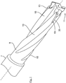
- Fig. 1 and 2 is a reamer designed as a reamer for surface treatment of a later on the basis of the Fig. 3 and 4 shown inner wall 1 of a core hole 3 of a workpiece 5.
- the drilling tool has a clamping shank 7 for clamping in a drill chuck, not shown, of a drilling device and a drill body 9 adjoining it.
- a drill body 9 adjoining it.
- two drill webs 13 along a longitudinal axis L and coiled around the longitudinal axis L. Between the two drill webs 13, flutes 15 are arranged.
- a set of cutting edges 17 ( Fig. 5 ) formed, each having a main cutting edge 19 and a grooved cutting edge 21.
- the two cutting sets 17 are arranged symmetrically with respect to the longitudinal axis L in order to ensure a uniform cutting load on the drilling tool.
- the main and groove cutting edges 19, 21 are designed as separate insert parts which are fastened to the drilling body 9 by means of screw connections, not shown, for example.
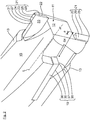
- the groove cutting edge 21 arranged in the respective cutting set 17 has a radially outwardly projecting groove base cutting edge 23. This extends according to the Fig. 2 or 4 along the longitudinal axis L between a front cutting corner 25 and a cutting corner 27 facing away from it.
- the groove base cutting edge 23 merges at the front cutting corner 25 into an end cutting edge 29 which extends at the drill tip 11 transversely to the longitudinal axis L and a drill end face 12 with a supernatant a ( Fig. 2 ) towers over.
- a groove flank cutting edge 31 (also transverse to the longitudinal axis L of the drill body) closes ( Fig. 2 or 4 ) on.
- a rake face 33 with free surfaces 22, 24 of the groove cutting edge 21 converge, which connect to the respective cutting edges with a clearance angle.
- the main cutting edge 19 is offset by a longitudinal offset ⁇ x ( Fig. 2 ) from the upstream groove 21 of the respective cutting set 17 spaced in the direction of rotation R.
- the main cutting edge 19 is formed with a radially outer cutting edge 35 which extends along the longitudinal axis L to one of the drill tips 11 facing cutting edge 37 extends.
- the cutting edge 35 goes on the cutting corner 37 into a body edge 39 running transversely to the longitudinal axis L of the drill body ( Fig. 2 or 4 ) about. Both the body edge 39 and the cutting corner 37 are in the boring process without material intervention with the inner wall of the core bore 1. Fig. 2 ) on.
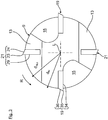
- Fig. 3 lies the groove base cutting edge 23 on a cutting diameter d groove which is smaller by a difference than the cutting diameter d N defining the nominal diameter of the bore 3 of the radially outer cutting edge 35 of the main cutting edge 19.
- the difference can be, for example, 50 ⁇ m or less.
- the two cutting diameters can also be designed identically.
- Fig. 4 and 5 Based on Fig. 4 and 5 the method for surface treatment of the inner wall of the core bore 1 is shown. For easier understanding are in the Fig. 4 and 5 only the groove and main cutting edges 19, 21 of a single cutting set 17 are shown, with the drilling body 9 omitted Fig. 5 the surface of the inner wall 1 that has already been machined is marked with horizontal lines that refer to a nominal diameter d N ( Fig. 4 ) is bored out. As a result, the drilling tool is driven into the workpiece core bore 3 in a combined rotation and feed movement R, V, which has a core diameter d core ( Fig. 4 ) having.
- the rotational movement R and the axial feed V of the drilling tool is designed in such a way that the groove cutting edge 21 creates a spiral groove 43 in the core bore inner wall 1, which according to FIG Fig. 4 has a radially outer groove base 45 and lateral groove flanks 47, 49.
- the groove 43 is generated with the aid of the radially outer groove base cutting edge 23, which in the FIG. 3 and 4 the upper groove flank cutting edge 31 and the end cutting edge 29 of the groove cutting edge 21.
- the groove width of the groove 43 generated is to be designed to be correspondingly small.
- the groove depth ⁇ t ( Fig. 4 ) the groove 43 is, for example, identical to the material thickness to be removed from the trailing main cutting edge 19.
- FIG. 6 and 7 Another embodiment of the drilling tool is shown.
- the basic structure and the mode of operation are identical to the drilling tool of the previous exemplary embodiments.
- each cutting set 17 there is provided a grooved cutting edge 21 and an associated main cutting edge 19 which is connected downstream of the grooved cutting edge 21 in the direction of rotation of the tool.
- the groove base cutting edge 23 is dimensioned to be comparatively small, so that the groove produced has a groove width that is reduced in comparison with the previous exemplary embodiment having. In this way, the cutting load on the cutting edge 21 can be prevented further.
Landscapes
- Engineering & Computer Science (AREA)
- Mechanical Engineering (AREA)
- Drilling Tools (AREA)
Description
Die Erfindung betrifft ein Bohrwerkzeug, insbesondere eine Reibahle, nach dem Oberbegriff des Patentanspruches 1 sowie ein Verfahren zur Oberflächenbearbeitung einer Innenwandung einer vorgebohrten Werkstück-Kernbohrung nach dem Patentanspruch 7. Ein solches Werkzeug und ein solches Verfahren sind aus der
Aus der
Mit der obigen Reibahle erfolgt die Oberflächenbearbeitung der Kernbohrung zweistufig mit den folgenden Bearbeitungsschritten: In einem ersten Vorbearbeitungsschritt wird die Reibahle zunächst mit geringer Drehzahl sowie darauf abgestimmter Vorschubgeschwindigkeit in die Kernbohrung eingefahren, wodurch die Nutschneide in der Kernbohrungs-Innenwandung eine spiralförmige Nut erzeugt. Im vollständig eingefahrenen Zustand befindet sich die an die Nutschneide anschließende Hauptschneide bereits vollständig in Eingriff mit der spiralförmigen Nut. Im anschließenden zweiten Bearbeitungsschritt kann die Hauptschneide der Reibahle unter Rotation, jedoch ohne Axialvorschub einen umfangsseitigen Materialabtrag vornehmen.With the above reamer, the surface machining of the core bore is carried out in two stages with the following processing steps: In a first preprocessing step, the reamer is first inserted into the core bore at low speed and with the feed speed matched to it, as a result of which the flute cutting edge in the inner bore of the core bore creates a spiral groove. In the fully retracted state, the main cutting edge adjoining the groove cutting edge is already fully engaged with the spiral groove. In the subsequent second Machining step, the main cutting edge of the reamer can remove material on the circumference while rotating, but without axial feed.
Die beiden Bearbeitungsschritte sind zeitaufwändig hintereinander durchzuführen. Zudem ist beim zweiten Bearbeitungsschritt der mit der Hauptschneide durchgeführte umfangsseitige Materialabtrag mit einer hohen Schneidbelastung verbunden. Um daher einen vorzeitigen Werkzeugbruch zu vermeiden, wird die obige Reibahle bevorzugt bei der Bearbeitung weicherer Werkstoffe, etwa Aluminium, einsetzbar ist.The two processing steps are time-consuming to perform consecutively. In addition, in the second machining step, the peripheral material removal carried out with the main cutting edge is associated with a high cutting load. Therefore, in order to avoid premature tool breakage, the above reamer is preferably used when machining softer materials, such as aluminum.
Die Aufgabe der Erfindung besteht darin, ein Bohrwerkzeug, insbesondere Reibahle, bereitzustellen, bei der im Vergleich zum Stand der Technik trotz höherer Fertigungsgeschwindigkeiten eine Schneidbelastung des Bohrwerkzeuges reduziert wird.The object of the invention is to provide a drilling tool, in particular a reamer, in which a cutting load on the drilling tool is reduced in comparison to the prior art, despite higher production speeds.
Die Aufgabe ist durch die Merkmale des Patentanspruches 1 oder des Patentanspruches 7 gelöst. Bevorzugte Weiterbildungen der Erfindung sind in den Unteransprüchen offenbart.The object is solved by the features of
Die Erfindung beruht auf dem Sachverhalt, dass mit der oben dargelegten, aus dem Stand der Technik bekannten Reibahle lediglich eine zeitaufwändige zweistufige Bearbeitung ermöglicht ist. Vor diesem Hintergrund weist das Bohrwerkzeug gemäß dem kennzeichnenden Teil des Patentanspruches 1 zumindest eine Nutschneide auf, die der, der Bohrerspitze zugewandten Schneidenecke der Hauptschneide in der Werkzeug-Rotationsrichtung vorgelagert ist. Im Aufbohrvorgang erzeugt die vorgelagerte Nutschneide eine Nut, die der Schneidenecke der Hauptschneide vorauseilt. In der vorauseilenden Nut ist die Schneidenecke der Hauptschneide geführt, und zwar im Wesentlichen ohne Schneidbelastung. Auf diese Weise kann das Bohrwerkzeug auch in Verbindung mit festeren Werkstoffen eingesetzt werden, ohne dass es zu einem vorzeitigen Werkzeugbruch kommt.The invention is based on the fact that only a time-consuming two-stage machining is possible with the above-described reamer known from the prior art. Against this background, the drilling tool according to the characterizing part of
Bei herkömmlichen Reibahlen ist die Schneidenecke der Hauptschneide an der Bohrerspitze dagegen sehr hohen Schneidbelastungen ausgesetzt. In einem solchen gängigen Bohrwerkzeug geht die seitliche Hauptschneide an ihrer stirnseitigen Schneidenecke in eine stirnseitige Querschneide über, mit der ein zusätzlicher Materialabtrag an der Kernbohrungs-Innenwandung erfolgt. Erfindungsgemäß wird dagegen die Hauptschneide ohne eine solche stirnseitige Querschneide ausgelegt.In contrast, with conventional reamers the cutting edge of the main cutting edge at the drill tip is exposed to very high cutting loads. In such a common drilling tool, the lateral main cutting edge at its cutting edge on the front side merges into a front cutting edge with which additional material removal takes place on the inner wall of the core bore. According to the invention, however, the main cutting edge is designed without such a transverse cutting edge.
Die von der Nutschneide im Aufbohrvorgang erzeugte spiralförmige Nut weist einen über eine Nuttiefe radial nach außen zurückgesetzten Nutgrund auf, der über seitlich hochgezogene Nutflanken in die Kernbohrungs-Innenwandung übergeht. Zur Erzeugung der Nut weist die Nutschneide stirnseitig an der Bohrerspitze eine quer zur Bohrkörper-Längsachse verlaufende Stirnschneidkante auf. Die Stirnschneidkante geht an einer stirnseitigen Schneidenecke in eine entlang der Bohrkörper-Längsachse verlaufende, radial äußere Nutgrund-Schneidkante über. Die Nutgrund-Schneidkante erstreckt sich bis zu einer von der Bohrerspitze abgewandten weiteren Schneidenecke, an die sich eine quer zur Bohrkörper-Längsachse verlaufende, weitere Nutflanken-Schneidenkante anschließt.The spiral groove produced by the groove cutting edge in the boring process has a groove base which is recessed radially outwards over a groove depth and which merges into the inner wall of the core hole via groove flanks which are pulled up laterally. To create the groove, the groove cutting edge has an end cutting edge running transversely to the longitudinal axis of the drill body on the face of the drill tip. The front cutting edge merges at a front cutting edge into a radially outer groove base cutting edge running along the longitudinal axis of the drill body. The groove base cutting edge extends to a further cutting corner facing away from the drill tip, which is followed by a further groove flank cutting edge running transverse to the longitudinal axis of the drill body.
Mit dem erfindungsgemäßen Bohrwerkzeug erfolgt der Aufbohrvorgang nicht mehr zweistufig, sondern in einer Einschussbearbeitung. Das Bohrwerkzeug kann dabei insbesondere bei Verfahren für eine Finish- oder Schrubb-Bearbeitung zur Herstellung hochgenauer Bohrungen eingesetzt werden. Beim Aufbohrvorgang wird das Bohrwerkzeug in einer kombinierten Rotations- und Vorschubbewegung in die Kernbohrung eingefahren. Die Rotations- und Vorschubbewegungen sind dabei so aufeinander abgestimmt, dass die stirnseitige Schneidenecke der Hauptschneide ohne Schneidbelastung in der spiralförmigen Nut geführt ist, die mittels der vorauseilenden Nutschneide in die Kernbohrungs-Innenwandung erzeugt wird. Die Hauptschneide bewirkt beim Aufbohrvorgang somit ausschließlich eine radial äußere Schälbearbeitung, während die Nutschneide sowohl in Radialrichtung als auch in Axialrichtung Material von der Kernbohrungs-Innenwandung abträgt.With the drilling tool according to the invention, the boring process is no longer carried out in two stages, but in one-shot machining. The drilling tool can be used in particular in processes for finishing or scrubbing for the production of high-precision bores. During the boring process, the drilling tool is inserted into the core bore in a combined rotation and feed movement. The rotation and feed movements are coordinated so that the frontal cutting corner of the main cutting edge is guided without cutting load in the spiral groove, which is generated by means of the leading cutting edge in the core bore inner wall. The main cutting edge thus only causes a radially outer peeling process during the boring process, while the grooving cutting edge removes material from the inner bore of the core bore both in the radial direction and in the axial direction.
Nachfolgend wird die Schneidengeometrie des Bohrwerkzeugs detaillierter beschrieben: So läuft an der stirnseitigen Nutflanken-Schneide eine Nutspanfläche und eine an der Bohrerspitze ausgebildete Hauptfreifläche zusammen. Die Nut-Spanfläche und die stirnseitige Hauptfreifläche spannen einen Keilwinkel auf. Im Hinblick auf die Auslegung der Vorschubgeschwindigkeit in Axialrichtung ist unter anderem auch ein Freiwinkel von Bedeutung, der durch die Hauptfreifläche definiert ist. Bei einer Erhöhung der Vorschubgeschwindigkeit ist auch der Freiwinkel zu erhöhen. Dies geht jedoch mit einer Reduzierung des Keilwinkels der Stirnschneide einher, wodurch die Gefahr von vorzeitigem Verschleiß sowie Werkzeugbruch erhöht ist.The cutting geometry of the drilling tool is described in more detail below: For example, a groove chip surface and a main free surface formed on the drill tip converge on the front groove flank cutting edge. The groove rake face and the front main free face span a wedge angle. With regard to the design of the feed speed in the axial direction, a clearance angle, which is defined by the main clearance area, is also important. If the feed speed is increased, the clearance angle must also be increased. However, this is accompanied by a reduction in the wedge angle of the end cutting edge, which increases the risk of premature wear and tool breakage.
An der, von der Bohrerspitze abgewandten Nutflanken-Schneidkante sowie an der Nutgrund-Schneidkante geht die Spanfläche in weitere, radial äußere Freiflächen über, die einen Freiwinkel mit einer gedachten Kreislinie aufspannen, entlang der sich die Nutflanken-Schneidkante und die Nutgrund-Schneidkante bewegen.On the groove flank cutting edge facing away from the drill tip and on the groove bottom cutting edge, the rake surface merges into further, radially outer free surfaces that span a clearance angle with an imaginary circular line along which the groove flank cutting edge and the groove bottom cutting edge move.
Die Schneidenecke der Hauptschneide ist um einen Längsversatz von der Nutschneide beabstandet. Der Längsversatz ist so ausgelegt, dass in Abstimmung mit dem Axialvorschub und der Rotationsbewegung die Schneidenecke der Hauptschneide in der vorauseilenden Nut geführt ist.The cutting edge of the main cutting edge is spaced apart from the grooving cutting edge by a longitudinal offset. The longitudinal offset is designed so that the cutting edge of the main cutting edge is guided in the leading groove in coordination with the axial feed and the rotational movement.
Bevorzugt kann die Nuttiefe der spiralförmig in der Kernbohrungs-innenwandung verlaufenden Nut identisch sein mit der von der Hauptschneide abzutragenden Materialstärke oder geringfügig kleiner ausgelegt sein. Entsprechend kann die Nutgrund-Schneidenkante auf einem Schneidendurchmesser liegen, der kleiner als der oder gleich dem Schneidendurchmesser der Schneidenkante der Hauptschneide ist.The groove depth of the groove running spirally in the inner wall of the core bore may preferably be identical to the material thickness to be removed from the main cutting edge or may be designed to be slightly smaller. Accordingly, the groove base cutting edge can lie on a cutting diameter which is smaller than or equal to the cutting diameter of the cutting edge of the main cutting edge.
Zudem ist es bevorzugt, wenn die in der Werkzeug-Rotationsrichtung nacheilende Hauptschneide die vorauseilende Nutschneide mit einem vorgegebenen Überstand entgegen der Vorschubrichtung überlappt. Dadurch kann nach der Erzeugung der spiralförmigen Nut ein noch unbearbeiteter, verbleibender Materialsteg von der nacheilenden Hauptschneide bis auf den Nenndurchmesser abgetragen werden.In addition, it is preferred if the main cutting edge lagging in the tool rotation direction overlaps the leading groove cutting edge with a predetermined protrusion against the feed direction. As a result, after the spiral groove has been created, a still unprocessed, remaining material web can be removed from the trailing main cutting edge down to the nominal diameter.
Bevorzugt ist die stirnseitige Schneidenecke der Hauptschneide vollständig außer Materialeingriff in der spiralförmigen Nut geführt. Hierzu kann die stirnseitige Schneidenecke der Hauptschneide um einen lichten Freiraum von einer, in der Vorschubrichtung vorgelagerten Nutflanke der Nut beabstandet sein.The front cutting edge of the main cutting edge is preferably guided completely out of material engagement in the spiral groove. For this purpose, the front cutting corner of the main cutting edge can be spaced apart by a clear space from a groove flank of the groove located upstream in the feed direction.
Die Hauptschneide sowie die Nutschneide bilden zusammen einen Schneidensatz. Bevorzugt können zwei, drei oder noch mehr Schneidensätze umfangsverteilt am Bohrwerkzeug angeordnet sein. In einer Ausführungsform kann der Schneidensatz nicht nur eine einzige Hauptschneide aufweisen, sondern vielmehr in der Rotationsrichtung betrachtet zumindest zwei hintereinander angeordnete Hauptschneiden, die beide der voreilenden Nutschneide in der Rotationsrichtung nacheilen. Die von der Nutschneide erzeugte Nuttiefe kann bevorzugt bereits dem Nenndurchmesser der Bohrung entsprechen oder alternativ um ein Aufmaß kleiner sein als der Nenndurchmesser.The main cutting edge and the groove cutting edge together form a cutting set. Preferably two, three or even more cutting sets can be arranged circumferentially distributed on the drilling tool. In one embodiment, the cutting set can not only have a single main cutting edge, but rather, viewed in the direction of rotation, at least two main cutting edges arranged one behind the other, both of which lag the leading groove cutting edge in the direction of rotation. The groove depth produced by the groove cutting edge can preferably already correspond to the nominal diameter of the bore or, alternatively, can be an oversize smaller than the nominal diameter.
Die vorstehend erläuterten und/oder in den Unteransprüchen wiedergegebenen vorteilhaften Aus- und/oder Weiterbildungen der Erfindung können - außer zum Beispiel in den Fällen eindeutiger Abhängigkeiten oder unvereinbarer Alternativen - einzeln oder aber auch in beliebiger Kombination miteinander zur Anwendung kommen.The advantageous embodiments and / or further developments of the invention explained above and / or reproduced in the subclaims can - apart from, for example, in the case of clear dependencies or incompatible alternatives - be used individually or in any combination with one another.
Es zeigen:
- Fig. 1
- in einer perspektivischen Darstellung ein als Reibahle ausgeführtes Bohrwerkzeug;
- Fig. 2
- in einer Detailansicht die Werkzeugspitze des Bohrwerkzeugs;
- Fig. 3
- in einer Vorderansicht die Bohrerspitze des Bohrwerkzeuges;
- Fig. 4
- eine perspektivische, stark vereinfachte Teilansicht, die einen Aufbohrvorgang veranschaulicht;
- Fig. 5
- eine Ansicht entsprechend der
Fig. 4 , jedoch mit einer, in Abwicklung gezeigten Kernbohrungs-Innenwandung; - Fig. 6 und 7
- ein weiteres Ausführungsbeispiel des Bohrwerkzeugs.
- Fig. 1
- a perspective view of a drilling tool designed as a reamer;
- Fig. 2
- in a detailed view the tool tip of the drilling tool;
- Fig. 3
- in a front view the drill tip of the drilling tool;
- Fig. 4
- a perspective, greatly simplified partial view illustrating a boring process;
- Fig. 5
- a view corresponding to the
Fig. 4 , but with a core bore inner wall shown in development; - 6 and 7
- another embodiment of the drilling tool.
In den
In jedem der Bohrerstege 13 ist ein Schneidensatz 17 (
Wie aus der
Wie aus den Figuren weiter hervorgeht, ist die Hauptschneide 19 um einen Längsversatz Δx (
In der
Anhand der
In der
Zudem ist in den
In den
Claims (7)
- Drilling tool, in particular reamer, for drilling a workpiece core bore (3) to a nominal diameter (dN) by means of a main cutting edge (19), formed on a drilling body (9), which has a radially outer cutting edge (35) which extends longitudinally along a drilling body longitudinal axis (L) onto a cutting nose (37) disposed at the drilling tip (11), wherein in the drilling procedure the drilling tool can be driven into the workpiece core bore (3) using rotational movement (R) and advance movement (V), wherein the drilling tool has at least one groove cutter (21) which is positioned upstream of the cutting nose (37) of the main cutting edge (19) in the tool rotational direction (R), wherein the groove cutter (21) for generating the groove (43) has at the drilling tip (11) an end cutting edge (29), extending perpendicularly to the drilling body longitudinal axis (L), which at a cutting nose (25) transitions into a groove floor cutting edge (23), extending along the drilling body longitudinal axis (L), which transitions at a cutting nose (27) facing away from the drilling tip (11) into a groove flank cutting edge (31) extending perpendicularly to the drilling body longitudinal axis (L), and wherein on the end cutting edge (29) a groove rake face (33) and a main free surface (22) formed on the drilling tip (11) converge, wherein the rotational movement (R) and the advance movement (V) are designed such that in the drilling procedure the groove cutter (21) a groove (43) is generated in the inner wall (1) of the core bore (3), in which groove the cutting nose (37) of the main cutting edge (19) is guided with at least reduced cutting load, characterised in that on the groove flank cutting edge (31) facing away from the drilling tip and on the groove floor cutting edge (23) the rake face (33) transition into further free surfaces (24) turned radially to the outside, which in the rotational direction (R) adjoin on the cutting edges (31, 23) at a clearance angle, and that the cutting nose (37) of the main cutting edge (19) is spaced by a longitudinal offset (Δx) from the groove cutter (21).
- Drilling tool according to claim 1, characterised in that the groove floor cutting edge (23) is located on a cutting edge diameter (dNut) which is smaller than or equal to the cutting edge diameter (dHaupt) of the radially outer cutting edge (35) of the main cutting edge (19).
- Drilling tool according to claim 1 or 2, characterised in that the radially outer cutting edge (35) of the main cutting edge (19) transitions at the cutting nose (37), facing the drilling tip (11), into a body edge (39) which is substantially without cutting load by reason of material removal.
- Drilling tool according to any of the preceding claims, characterised in that viewed in rotational direction (R) at least two groove cutters (21) disposed one after another are provided, which are positioned upstream of the main cutting edge cutting nose (37).
- Drilling tool according to any of the preceding claims, characterised in that the at least one main cutting edge (19) and the at least one groove cutter (21) form a cutting tool (17), and that in particular at least one or several cutting tools (17) are formed on the drilling body.
- Drilling tool according to any of the preceding claims, characterised in that the main cutting edge (19) and the groove cutter (21) are two components separate from one another or are combined to form a shared cutting element.
- Method for drilling a pre-drilled workpiece core bore (3) to a nominal diameter (dN) by means of a drilling tool according to any of the preceding claims, in the case of which the drilling tool has at least one groove cutter (21), which is positioned upstream of a cutting nose (37) of a main cutting edge (19) in tool rotational direction (R), wherein the rotational movement (R) and the advance movement (V) are designed such that in the drilling procedure the groove cutter (21) generates in the inner wall (1) of the core bore (3) a groove (43) in which the cutting nose (37) of the main cutting edge (19) is guided with at least reduced cutting load, that the end-face-side cutting nose (37) of the main cutting edge (19) is guided without material engagement in the groove (43), and is spaced by a clear space (f) from a groove flank (49), positioned upstream in the advance direction (V), of the groove (43), and that after the generation of the groove (43) by means of the groove cutter (21) a still unprocessed material web (51) remains on the groove side (47) lying against the advance direction (V), which material web can be removed by the main cutting edge (19).
Applications Claiming Priority (2)
| Application Number | Priority Date | Filing Date | Title |
|---|---|---|---|
| DE102014014932.3A DE102014014932B4 (en) | 2014-10-07 | 2014-10-07 | Method for boring a pre-drilled workpiece core hole |
| PCT/EP2015/067579 WO2016055185A1 (en) | 2014-10-07 | 2015-07-30 | Drilling tool, in particular reamer |
Publications (2)
| Publication Number | Publication Date |
|---|---|
| EP3204180A1 EP3204180A1 (en) | 2017-08-16 |
| EP3204180B1 true EP3204180B1 (en) | 2020-01-29 |
Family
ID=53872022
Family Applications (1)
| Application Number | Title | Priority Date | Filing Date |
|---|---|---|---|
| EP15750668.4A Active EP3204180B1 (en) | 2014-10-07 | 2015-07-30 | Drilling tool, in particular reamer |
Country Status (5)
| Country | Link |
|---|---|
| US (1) | US9999935B2 (en) |
| EP (1) | EP3204180B1 (en) |
| CN (1) | CN106794530B (en) |
| DE (1) | DE102014014932B4 (en) |
| WO (1) | WO2016055185A1 (en) |
Families Citing this family (4)
| Publication number | Priority date | Publication date | Assignee | Title |
|---|---|---|---|---|
| USD892326S1 (en) * | 2018-01-31 | 2020-08-04 | Beijing Smtp Technology Co., Ltd. | Ultrasonic cutter head |
| USD882786S1 (en) * | 2018-01-31 | 2020-04-28 | Beijing Smtp Technology Co., Ltd. | Ultrasonic cutter head |
| USD882785S1 (en) * | 2018-01-31 | 2020-04-28 | Beijing Smtp Technology Co., Ltd. | Ultrasonic cutter head |
| DE102022115490A1 (en) * | 2022-06-22 | 2023-12-28 | Kennametal Inc. | Rotary drilling tool and method for producing a through hole |
Family Cites Families (23)
| Publication number | Priority date | Publication date | Assignee | Title |
|---|---|---|---|---|
| US370484A (en) * | 1887-09-27 | Counterbore | ||
| US327148A (en) * | 1885-09-29 | Metal-boring bit | ||
| US1000067A (en) * | 1911-03-16 | 1911-08-08 | Paul C Seegmueller | Drill. |
| US1439567A (en) * | 1919-11-14 | 1922-12-19 | J Faessler Mfg Company | Reamer |
| USRE16817E (en) * | 1920-09-20 | 1927-12-13 | Reaming and cotjnterboring tool | |
| US1752262A (en) * | 1928-09-20 | 1930-03-25 | Firm Of Peter Friedr Muhlhoff | Bit for boring long holes |
| US2630725A (en) * | 1951-06-15 | 1953-03-10 | United States Steel Corp | Multiple cutter boring device |
| DE2750705A1 (en) * | 1977-11-12 | 1979-05-17 | Wezel & Co Biax Werkzeuge | REAMER WITH DRILLING STEP AND HIGHLY UNEQUAL PITCHING OF THE REAMER CUTTERS |
| US4274771A (en) * | 1979-06-28 | 1981-06-23 | G. N. Tool Inc. | Boring reamer with end mill cutters |
| US4948305A (en) * | 1988-12-23 | 1990-08-14 | Gte Valenite Corporation | Boring bar |
| JP2981055B2 (en) | 1992-04-28 | 1999-11-22 | 富士精工株式会社 | Burnishing drill |
| DE4437542B4 (en) * | 1994-10-20 | 2004-10-14 | August Beck Gmbh & Co | Kegelaufbohrer |
| DE10124234B4 (en) | 2001-05-18 | 2007-02-01 | Wilhelm Fette Gmbh | Rotary milling tool |
| JP4107106B2 (en) * | 2003-02-28 | 2008-06-25 | 三菱マテリアル株式会社 | Drilling tool |
| US8025662B2 (en) * | 2004-03-25 | 2011-09-27 | Symmetry Medical, Inc. | Bidirectional reaming cutter |
| US20070020057A1 (en) * | 2005-07-25 | 2007-01-25 | Yih Troun Enterprise Co., Ltd. | Drill bit with multiple stepped cutting edges |
| US8714890B2 (en) * | 2007-02-09 | 2014-05-06 | The Boeing Company | Cutter for drilling and reaming |
| US9168601B2 (en) * | 2010-11-17 | 2015-10-27 | Kennametal Inc. | Multi-flute reamer and cutting insert therefor |
| DE102010054476B4 (en) | 2010-12-14 | 2016-07-07 | Audi Ag | Method for producing a thread in a workpiece |
| CN202411558U (en) | 2011-11-25 | 2012-09-05 | 郑州市钻石精密制造有限公司 | Rough and finish integral machining diamond reamer |
| DE102012007514A1 (en) | 2012-03-16 | 2013-09-19 | Audi Ag | Method and tool for machining a precisely fitting, cylindrical bore from an existing bore with finishing allowance |
| DE102012021275B4 (en) | 2012-10-29 | 2014-05-15 | Audi Ag | Method for surface machining of workpieces |
| DE102013004105A1 (en) * | 2013-03-11 | 2014-09-11 | Audi Ag | Drilling tool, in particular reamer |
-
2014
- 2014-10-07 DE DE102014014932.3A patent/DE102014014932B4/en not_active Expired - Fee Related
-
2015
- 2015-07-30 WO PCT/EP2015/067579 patent/WO2016055185A1/en active Application Filing
- 2015-07-30 US US15/514,693 patent/US9999935B2/en active Active
- 2015-07-30 EP EP15750668.4A patent/EP3204180B1/en active Active
- 2015-07-30 CN CN201580054297.2A patent/CN106794530B/en active Active
Non-Patent Citations (1)
| Title |
|---|
| None * |
Also Published As
| Publication number | Publication date |
|---|---|
| DE102014014932A1 (en) | 2016-04-07 |
| US20170216945A1 (en) | 2017-08-03 |
| DE102014014932B4 (en) | 2020-12-31 |
| CN106794530A (en) | 2017-05-31 |
| EP3204180A1 (en) | 2017-08-16 |
| US9999935B2 (en) | 2018-06-19 |
| WO2016055185A1 (en) | 2016-04-14 |
| CN106794530B (en) | 2018-06-22 |
Similar Documents
| Publication | Publication Date | Title |
|---|---|---|
| EP3484647B1 (en) | Method for the production of a threaded hole and tool for this method | |
| EP3458219B1 (en) | Method for producing a threaded borehole and tapping tool | |
| EP3471908B1 (en) | Tool to produce an internal thread in the predrilled hole of a workpiece | |
| EP3433044B1 (en) | Method and machine for the machining of a threaded hole | |
| EP3784430B1 (en) | Tapping tool and method for producing a threaded bore | |
| EP3204180B1 (en) | Drilling tool, in particular reamer | |
| EP2969344B1 (en) | Drilling tool, in particular reamer | |
| DE102020109035B4 (en) | Method and tapping tool for producing a tapped hole in a workpiece | |
| EP3887084B1 (en) | Tapping tool and method for producing a tapped hole | |
| EP3908420B1 (en) | Tapping tool for producing a threaded hole | |
| EP3142819B1 (en) | Tool for roughening a metallic surface and method for roughening a metallic surface with such a roughening tool | |
| EP4025369B1 (en) | Method for producing a workpiece tapped hole | |
| DE19548199A1 (en) | Process for producing a threaded bore and tool for carrying out such a process | |
| DE102018206540A1 (en) | Tapping tool and method for creating a threaded hole | |
| DE102018206543B4 (en) | Tapping tool and method for creating a threaded hole | |
| EP4035812A1 (en) | Method for manufacturing a workpiece through hole and deburring tool |
Legal Events
| Date | Code | Title | Description |
|---|---|---|---|
| STAA | Information on the status of an ep patent application or granted ep patent |
Free format text: STATUS: THE INTERNATIONAL PUBLICATION HAS BEEN MADE |
|
| PUAI | Public reference made under article 153(3) epc to a published international application that has entered the european phase |
Free format text: ORIGINAL CODE: 0009012 |
|
| STAA | Information on the status of an ep patent application or granted ep patent |
Free format text: STATUS: REQUEST FOR EXAMINATION WAS MADE |
|
| 17P | Request for examination filed |
Effective date: 20170508 |
|
| AK | Designated contracting states |
Kind code of ref document: A1 Designated state(s): AL AT BE BG CH CY CZ DE DK EE ES FI FR GB GR HR HU IE IS IT LI LT LU LV MC MK MT NL NO PL PT RO RS SE SI SK SM TR |
|
| AX | Request for extension of the european patent |
Extension state: BA ME |
|
| DAV | Request for validation of the european patent (deleted) | ||
| DAX | Request for extension of the european patent (deleted) | ||
| GRAP | Despatch of communication of intention to grant a patent |
Free format text: ORIGINAL CODE: EPIDOSNIGR1 |
|
| STAA | Information on the status of an ep patent application or granted ep patent |
Free format text: STATUS: GRANT OF PATENT IS INTENDED |
|
| INTG | Intention to grant announced |
Effective date: 20191107 |
|
| GRAS | Grant fee paid |
Free format text: ORIGINAL CODE: EPIDOSNIGR3 |
|
| GRAA | (expected) grant |
Free format text: ORIGINAL CODE: 0009210 |
|
| STAA | Information on the status of an ep patent application or granted ep patent |
Free format text: STATUS: THE PATENT HAS BEEN GRANTED |
|
| AK | Designated contracting states |
Kind code of ref document: B1 Designated state(s): AL AT BE BG CH CY CZ DE DK EE ES FI FR GB GR HR HU IE IS IT LI LT LU LV MC MK MT NL NO PL PT RO RS SE SI SK SM TR |
|
| REG | Reference to a national code |
Ref country code: GB Ref legal event code: FG4D Free format text: NOT ENGLISH |
|
| REG | Reference to a national code |
Ref country code: CH Ref legal event code: EP |
|
| REG | Reference to a national code |
Ref country code: AT Ref legal event code: REF Ref document number: 1228124 Country of ref document: AT Kind code of ref document: T Effective date: 20200215 |
|
| REG | Reference to a national code |
Ref country code: IE Ref legal event code: FG4D Free format text: LANGUAGE OF EP DOCUMENT: GERMAN |
|
| REG | Reference to a national code |
Ref country code: DE Ref legal event code: R096 Ref document number: 502015011605 Country of ref document: DE |
|
| REG | Reference to a national code |
Ref country code: NL Ref legal event code: MP Effective date: 20200129 |
|
| PG25 | Lapsed in a contracting state [announced via postgrant information from national office to epo] |
Ref country code: NO Free format text: LAPSE BECAUSE OF FAILURE TO SUBMIT A TRANSLATION OF THE DESCRIPTION OR TO PAY THE FEE WITHIN THE PRESCRIBED TIME-LIMIT Effective date: 20200429 Ref country code: PT Free format text: LAPSE BECAUSE OF FAILURE TO SUBMIT A TRANSLATION OF THE DESCRIPTION OR TO PAY THE FEE WITHIN THE PRESCRIBED TIME-LIMIT Effective date: 20200621 Ref country code: RS Free format text: LAPSE BECAUSE OF FAILURE TO SUBMIT A TRANSLATION OF THE DESCRIPTION OR TO PAY THE FEE WITHIN THE PRESCRIBED TIME-LIMIT Effective date: 20200129 Ref country code: FI Free format text: LAPSE BECAUSE OF FAILURE TO SUBMIT A TRANSLATION OF THE DESCRIPTION OR TO PAY THE FEE WITHIN THE PRESCRIBED TIME-LIMIT Effective date: 20200129 |
|
| REG | Reference to a national code |
Ref country code: LT Ref legal event code: MG4D |
|
| PG25 | Lapsed in a contracting state [announced via postgrant information from national office to epo] |
Ref country code: IS Free format text: LAPSE BECAUSE OF FAILURE TO SUBMIT A TRANSLATION OF THE DESCRIPTION OR TO PAY THE FEE WITHIN THE PRESCRIBED TIME-LIMIT Effective date: 20200529 Ref country code: BG Free format text: LAPSE BECAUSE OF FAILURE TO SUBMIT A TRANSLATION OF THE DESCRIPTION OR TO PAY THE FEE WITHIN THE PRESCRIBED TIME-LIMIT Effective date: 20200429 Ref country code: HR Free format text: LAPSE BECAUSE OF FAILURE TO SUBMIT A TRANSLATION OF THE DESCRIPTION OR TO PAY THE FEE WITHIN THE PRESCRIBED TIME-LIMIT Effective date: 20200129 Ref country code: SE Free format text: LAPSE BECAUSE OF FAILURE TO SUBMIT A TRANSLATION OF THE DESCRIPTION OR TO PAY THE FEE WITHIN THE PRESCRIBED TIME-LIMIT Effective date: 20200129 Ref country code: LV Free format text: LAPSE BECAUSE OF FAILURE TO SUBMIT A TRANSLATION OF THE DESCRIPTION OR TO PAY THE FEE WITHIN THE PRESCRIBED TIME-LIMIT Effective date: 20200129 Ref country code: GR Free format text: LAPSE BECAUSE OF FAILURE TO SUBMIT A TRANSLATION OF THE DESCRIPTION OR TO PAY THE FEE WITHIN THE PRESCRIBED TIME-LIMIT Effective date: 20200430 |
|
| PG25 | Lapsed in a contracting state [announced via postgrant information from national office to epo] |
Ref country code: NL Free format text: LAPSE BECAUSE OF FAILURE TO SUBMIT A TRANSLATION OF THE DESCRIPTION OR TO PAY THE FEE WITHIN THE PRESCRIBED TIME-LIMIT Effective date: 20200129 |
|
| PG25 | Lapsed in a contracting state [announced via postgrant information from national office to epo] |
Ref country code: CZ Free format text: LAPSE BECAUSE OF FAILURE TO SUBMIT A TRANSLATION OF THE DESCRIPTION OR TO PAY THE FEE WITHIN THE PRESCRIBED TIME-LIMIT Effective date: 20200129 Ref country code: ES Free format text: LAPSE BECAUSE OF FAILURE TO SUBMIT A TRANSLATION OF THE DESCRIPTION OR TO PAY THE FEE WITHIN THE PRESCRIBED TIME-LIMIT Effective date: 20200129 Ref country code: LT Free format text: LAPSE BECAUSE OF FAILURE TO SUBMIT A TRANSLATION OF THE DESCRIPTION OR TO PAY THE FEE WITHIN THE PRESCRIBED TIME-LIMIT Effective date: 20200129 Ref country code: SK Free format text: LAPSE BECAUSE OF FAILURE TO SUBMIT A TRANSLATION OF THE DESCRIPTION OR TO PAY THE FEE WITHIN THE PRESCRIBED TIME-LIMIT Effective date: 20200129 Ref country code: RO Free format text: LAPSE BECAUSE OF FAILURE TO SUBMIT A TRANSLATION OF THE DESCRIPTION OR TO PAY THE FEE WITHIN THE PRESCRIBED TIME-LIMIT Effective date: 20200129 Ref country code: EE Free format text: LAPSE BECAUSE OF FAILURE TO SUBMIT A TRANSLATION OF THE DESCRIPTION OR TO PAY THE FEE WITHIN THE PRESCRIBED TIME-LIMIT Effective date: 20200129 Ref country code: SM Free format text: LAPSE BECAUSE OF FAILURE TO SUBMIT A TRANSLATION OF THE DESCRIPTION OR TO PAY THE FEE WITHIN THE PRESCRIBED TIME-LIMIT Effective date: 20200129 Ref country code: DK Free format text: LAPSE BECAUSE OF FAILURE TO SUBMIT A TRANSLATION OF THE DESCRIPTION OR TO PAY THE FEE WITHIN THE PRESCRIBED TIME-LIMIT Effective date: 20200129 |
|
| REG | Reference to a national code |
Ref country code: DE Ref legal event code: R097 Ref document number: 502015011605 Country of ref document: DE |
|
| PLBE | No opposition filed within time limit |
Free format text: ORIGINAL CODE: 0009261 |
|
| STAA | Information on the status of an ep patent application or granted ep patent |
Free format text: STATUS: NO OPPOSITION FILED WITHIN TIME LIMIT |
|
| 26N | No opposition filed |
Effective date: 20201030 |
|
| PG25 | Lapsed in a contracting state [announced via postgrant information from national office to epo] |
Ref country code: IT Free format text: LAPSE BECAUSE OF FAILURE TO SUBMIT A TRANSLATION OF THE DESCRIPTION OR TO PAY THE FEE WITHIN THE PRESCRIBED TIME-LIMIT Effective date: 20200129 |
|
| PG25 | Lapsed in a contracting state [announced via postgrant information from national office to epo] |
Ref country code: MC Free format text: LAPSE BECAUSE OF FAILURE TO SUBMIT A TRANSLATION OF THE DESCRIPTION OR TO PAY THE FEE WITHIN THE PRESCRIBED TIME-LIMIT Effective date: 20200129 Ref country code: SI Free format text: LAPSE BECAUSE OF FAILURE TO SUBMIT A TRANSLATION OF THE DESCRIPTION OR TO PAY THE FEE WITHIN THE PRESCRIBED TIME-LIMIT Effective date: 20200129 Ref country code: PL Free format text: LAPSE BECAUSE OF FAILURE TO SUBMIT A TRANSLATION OF THE DESCRIPTION OR TO PAY THE FEE WITHIN THE PRESCRIBED TIME-LIMIT Effective date: 20200129 |
|
| REG | Reference to a national code |
Ref country code: CH Ref legal event code: PL |
|
| REG | Reference to a national code |
Ref country code: BE Ref legal event code: MM Effective date: 20200731 |
|
| PG25 | Lapsed in a contracting state [announced via postgrant information from national office to epo] |
Ref country code: LI Free format text: LAPSE BECAUSE OF NON-PAYMENT OF DUE FEES Effective date: 20200731 Ref country code: LU Free format text: LAPSE BECAUSE OF NON-PAYMENT OF DUE FEES Effective date: 20200730 Ref country code: CH Free format text: LAPSE BECAUSE OF NON-PAYMENT OF DUE FEES Effective date: 20200731 |
|
| PG25 | Lapsed in a contracting state [announced via postgrant information from national office to epo] |
Ref country code: BE Free format text: LAPSE BECAUSE OF NON-PAYMENT OF DUE FEES Effective date: 20200731 |
|
| PG25 | Lapsed in a contracting state [announced via postgrant information from national office to epo] |
Ref country code: IE Free format text: LAPSE BECAUSE OF NON-PAYMENT OF DUE FEES Effective date: 20200730 |
|
| REG | Reference to a national code |
Ref country code: AT Ref legal event code: MM01 Ref document number: 1228124 Country of ref document: AT Kind code of ref document: T Effective date: 20200730 |
|
| PG25 | Lapsed in a contracting state [announced via postgrant information from national office to epo] |
Ref country code: AT Free format text: LAPSE BECAUSE OF NON-PAYMENT OF DUE FEES Effective date: 20200730 |
|
| PG25 | Lapsed in a contracting state [announced via postgrant information from national office to epo] |
Ref country code: TR Free format text: LAPSE BECAUSE OF FAILURE TO SUBMIT A TRANSLATION OF THE DESCRIPTION OR TO PAY THE FEE WITHIN THE PRESCRIBED TIME-LIMIT Effective date: 20200129 Ref country code: MT Free format text: LAPSE BECAUSE OF FAILURE TO SUBMIT A TRANSLATION OF THE DESCRIPTION OR TO PAY THE FEE WITHIN THE PRESCRIBED TIME-LIMIT Effective date: 20200129 Ref country code: CY Free format text: LAPSE BECAUSE OF FAILURE TO SUBMIT A TRANSLATION OF THE DESCRIPTION OR TO PAY THE FEE WITHIN THE PRESCRIBED TIME-LIMIT Effective date: 20200129 |
|
| PG25 | Lapsed in a contracting state [announced via postgrant information from national office to epo] |
Ref country code: MK Free format text: LAPSE BECAUSE OF FAILURE TO SUBMIT A TRANSLATION OF THE DESCRIPTION OR TO PAY THE FEE WITHIN THE PRESCRIBED TIME-LIMIT Effective date: 20200129 Ref country code: AL Free format text: LAPSE BECAUSE OF FAILURE TO SUBMIT A TRANSLATION OF THE DESCRIPTION OR TO PAY THE FEE WITHIN THE PRESCRIBED TIME-LIMIT Effective date: 20200129 |
|
| P01 | Opt-out of the competence of the unified patent court (upc) registered |
Effective date: 20230530 |
|
| PGFP | Annual fee paid to national office [announced via postgrant information from national office to epo] |
Ref country code: GB Payment date: 20230720 Year of fee payment: 9 |
|
| PGFP | Annual fee paid to national office [announced via postgrant information from national office to epo] |
Ref country code: FR Payment date: 20230721 Year of fee payment: 9 Ref country code: DE Payment date: 20230731 Year of fee payment: 9 |