EP3203922B1 - Behandlungsvorrichtung für endometriumschleimhaut - Google Patents
Behandlungsvorrichtung für endometriumschleimhaut Download PDFInfo
- Publication number
- EP3203922B1 EP3203922B1 EP15781558.0A EP15781558A EP3203922B1 EP 3203922 B1 EP3203922 B1 EP 3203922B1 EP 15781558 A EP15781558 A EP 15781558A EP 3203922 B1 EP3203922 B1 EP 3203922B1
- Authority
- EP
- European Patent Office
- Prior art keywords
- balloon
- treatment device
- flexures
- tissue treatment
- distal end
- Prior art date
- Legal status (The legal status is an assumption and is not a legal conclusion. Google has not performed a legal analysis and makes no representation as to the accuracy of the status listed.)
- Active
Links
Images


Classifications
-
- A—HUMAN NECESSITIES
- A61—MEDICAL OR VETERINARY SCIENCE; HYGIENE
- A61B—DIAGNOSIS; SURGERY; IDENTIFICATION
- A61B18/00—Surgical instruments, devices or methods for transferring non-mechanical forms of energy to or from the body
- A61B18/04—Surgical instruments, devices or methods for transferring non-mechanical forms of energy to or from the body by heating
- A61B18/12—Surgical instruments, devices or methods for transferring non-mechanical forms of energy to or from the body by heating by passing a current through the tissue to be heated, e.g. high-frequency current
- A61B18/14—Probes or electrodes therefor
- A61B18/1485—Probes or electrodes therefor having a short rigid shaft for accessing the inner body through natural openings
-
- A—HUMAN NECESSITIES
- A61—MEDICAL OR VETERINARY SCIENCE; HYGIENE
- A61M—DEVICES FOR INTRODUCING MEDIA INTO, OR ONTO, THE BODY; DEVICES FOR TRANSDUCING BODY MEDIA OR FOR TAKING MEDIA FROM THE BODY; DEVICES FOR PRODUCING OR ENDING SLEEP OR STUPOR
- A61M25/00—Catheters; Hollow probes
- A61M25/10—Balloon catheters
- A61M25/1002—Balloon catheters characterised by balloon shape
-
- A—HUMAN NECESSITIES
- A61—MEDICAL OR VETERINARY SCIENCE; HYGIENE
- A61B—DIAGNOSIS; SURGERY; IDENTIFICATION
- A61B17/00—Surgical instruments, devices or methods
- A61B17/42—Gynaecological or obstetrical instruments or methods
- A61B2017/4216—Operations on uterus, e.g. endometrium
- A61B2017/4225—Cervix uteri
-
- A—HUMAN NECESSITIES
- A61—MEDICAL OR VETERINARY SCIENCE; HYGIENE
- A61B—DIAGNOSIS; SURGERY; IDENTIFICATION
- A61B18/00—Surgical instruments, devices or methods for transferring non-mechanical forms of energy to or from the body
- A61B2018/00053—Mechanical features of the instrument of device
- A61B2018/00214—Expandable means emitting energy, e.g. by elements carried thereon
- A61B2018/0022—Balloons
-
- A—HUMAN NECESSITIES
- A61—MEDICAL OR VETERINARY SCIENCE; HYGIENE
- A61B—DIAGNOSIS; SURGERY; IDENTIFICATION
- A61B18/00—Surgical instruments, devices or methods for transferring non-mechanical forms of energy to or from the body
- A61B2018/00315—Surgical instruments, devices or methods for transferring non-mechanical forms of energy to or from the body for treatment of particular body parts
- A61B2018/00559—Female reproductive organs
-
- A—HUMAN NECESSITIES
- A61—MEDICAL OR VETERINARY SCIENCE; HYGIENE
- A61B—DIAGNOSIS; SURGERY; IDENTIFICATION
- A61B18/00—Surgical instruments, devices or methods for transferring non-mechanical forms of energy to or from the body
- A61B18/04—Surgical instruments, devices or methods for transferring non-mechanical forms of energy to or from the body by heating
- A61B18/12—Surgical instruments, devices or methods for transferring non-mechanical forms of energy to or from the body by heating by passing a current through the tissue to be heated, e.g. high-frequency current
- A61B18/14—Probes or electrodes therefor
- A61B2018/1475—Electrodes retractable in or deployable from a housing
-
- A—HUMAN NECESSITIES
- A61—MEDICAL OR VETERINARY SCIENCE; HYGIENE
- A61B—DIAGNOSIS; SURGERY; IDENTIFICATION
- A61B2218/00—Details of surgical instruments, devices or methods for transferring non-mechanical forms of energy to or from the body
- A61B2218/001—Details of surgical instruments, devices or methods for transferring non-mechanical forms of energy to or from the body having means for irrigation and/or aspiration of substances to and/or from the surgical site
- A61B2218/007—Aspiration
Definitions
- the disclosed inventions pertain generally to An endometrial tissue treatment device.
- Thermal ablation of the interior lining of a body organ is a procedure which involves heating the organ lining to a temperature that destroys the cells of the lining tissue. Such a procedure may be performed as a treatment to one of many conditions, such as menorrhagia, which is characterized by chronic bleeding of the endometrial tissue layer of the uterus.
- Existing methods for effecting thermal ablation of the endometrial lining tissue include circulation of heated fluid inside the uterus (either directly or inside a balloon placed in the uterus), laser treatment of the lining, and resistive heating using application of RF energy to the tissue to be ablated. Techniques using RF energy provide an RF electrical signal to one or more electrodes in contact with the subject organ tissue. Electrical current flows from the electrodes and into the organ tissue. The current flow resistively heats the surrounding tissue. Eventually, the heating process destroys the cells surrounding the electrodes and thereby effectuates ablation.
- U.S. Pat. Nos. 6,508,815 (Strul et al. ) and 6,813,520 (Truckai et al ) describe a system and method for endometrial lining tissue ablation using an electrode carrying member to transmit radiofrequency (RF) energy to cause thermal heating and, thus, ablation of the tissue, wherein the electrode carrying member is substantially absorbent or permeable to moisture and gases such as steam, and is expandable to conform to the uterine cavity.
- RF radiofrequency
- a suction (aspiration) lumen is positioned within the electrode carrying member to aid in the removal of moisture, whether gas or liquid, present or generated during the ablation procedure.
- the electrode carrying member comprises an array of electrodes on its outer surface, the electrode array being configured for contacting the endometrial lining tissue in order to deliver energy sufficient to produce ablation to a predetermined depth.
- the electrode carrying member is collapsed and introduced into the uterine cavity, and then expanded within the uterine cavity so that the electrode array contacts the endometrial lining tissue to be ablated.
- An RF generator is used to deliver RF energy to the electrodes and to thereby induce current flow from the electrodes through the endometrial lining tissue. As the current passes through and heats the endometrial lining tissue, moisture (such as steam or liquid) leaves the tissue causing the tissue to dehydrate.
- the moisture permeability or absorbency of the electrode carrying member allows for moisture to leave the ablation site through an aspiration lumen of the ablation device to a waste collection receptacle located external to the patient, so as to prevent the moisture from providing a path of conductivity for the current that bypasses (i.e., short-circuits) the conductive pathway through the tissue.
- U.S. Pat. Pub. No. 2011/0118718 also describes a system and method for endometrial RF ablation.
- This system uses an energy delivery device having a dielectric wall capable of non-expanded and expanded shapes, and having an indicator mechanism operatively coupled to the dielectric wall to indicate a dimension of the uterine wall.
- the document US 2005/0085880 A1 discloses an endometrial tissue treatment device according to the preamble of claim 1.
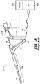
- FIGS. 1A-B illustrate an exemplary Novasure® endometrial ablation system 100.
- the ablation system 100 includes an expandable RF applicator head (electrode carrying member) 102, an introducer sheath 104, an introducer tubing 108, and a handle 106.
- the RF applicator head 102 is collapsed and slidably disposed within the introducer sheath 104 during insertion of the device into the uterine cavity via the introducer tubing 108 ( FIG. 1A ).
- the distal end of the sheath 104 is positioned within the uterus, and the handle 106 is manipulated to extend the RF applicator head 102 out an open distal end of the sheath 104 ( FIG.
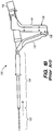
- the RF applicator head 102 includes a moisture permeable (woven) mesh electrode array 102a, and an underlying deflecting (i.e., expanding) mechanism 102b used to expand and tension the mesh electrode array 102a within the uterine cavity to facilitate contact between the endometrial lining tissue and the mesh electrode array 102a.
- the deflecting mechanism 102b includes a pair of metal ribbon flexures 124 extending distally and laterally out the introducer tubing 108 on opposite sides of a co-axially disposed pair of hypotubes 120 and 122 that also extend from tube 108.
- Non-conductive threads 148 extend from the inner hypotube 122 and have distal ends attached to internal flexures 136 that extend laterally and longitudinally from the exterior surface of hypotube 122.
- each flexure 124 includes conductive regions formed by isolated strips of metallic (e.g., copper) tape 128 that are electrically coupled to the array 102a for delivery of RF energy to the endometrial lining tissue.
- Anode and cathode conductors are electrically coupled to respective ones of the strips 128, and extend through the tubing 108 (seen in FIG.
- each internal flexure 136 is connected at its distal end to one of the flexures 124, the deflecting mechanism further including a transverse ribbon 138 that extends between the distal portions of the internal flexures 136.
- the transverse ribbon 138 is preferably pre-shaped such that when in the relaxed condition the ribbon assumes the corrugated configuration and such that when in a compressed condition it is folded along the plurality of creases 140 that extend along its length.
- Flexures 124 and 136, and ribbon 138 are preferably made of an insulated spring material, such as heat treated 17-7 PH stainless steel.
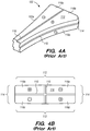
- the electrode array 102a further includes a pair of broad faces 112 spaced apart from one another when the array 102a is expanded and tensioned by the deflecting mechanism 102b ( FIG. 2, 3A and 4A ).
- the entire applicator head 102 is preferably coated with a dielectric material coating, such as parylene.
- Narrower side faces 114 extend between the broad faces 112 along the sides of the applicator head 102, and a distal face 116 extends between the broad faces 112 at the distal end of the applicator head 102.
- Insulating regions 110 are formed on the applicator head to divide the mesh into four electrodes 118a-118d by creating two electrodes on each of the broad faces 112. To create this four-electrode pattern, insulating regions 110 are placed longitudinally along each of the broad faces 112 as well as along the length of each of the faces 114, 116.
- distal and proximal grips 142 and 144 forming the handle 106 are squeezed towards one another to withdraw sheath 104 and deploy the applicator head 102 ( FIG. 1B ).
- This action results in relative rearward motion of the outer hypotube 120 and relative forward motion of the inner hypotube 122, causing deflection of flexures 124 and 136, thereby expanding and tensioning the electrode array 102a ( FIG. 2 ).
- the deflecting mechanism 102b formed by flexures 124, 136, and ribbon 138 deploys the electrode array 102a into a uterine shape.
- the ribbon 138 of the deflecting mechanism 102b further maintains electrodes 118a-118d separated and insulated from each other during use of the system 100, the ribbon 138 is usually not adapted to further assist the distal face 116 of the electrode array 102a to contact a uterine fundus.
- an endometrial tissue treatment device includes an elongate positioning member; and an energy applicator coupled to a distal end of the positioning member.
- the energy applicator includes a tissue contacting member (e.g., a moisture permeable energy delivery member), and an expandable-collapsible support structure underlying the tissue contacting member, the support structure including a substantially non-compliant elongate balloon that, when inflated, has a length oriented substantially transverse to the positioning member, including a first closed end that positions a corresponding first corner portion of the tissue contacting member in a first cornu of a uterine cavity, and a second closed end that positions a corresponding second corner portion of the tissue contacting member in a second cornu of the uterine cavity, with a lengthwise portion of the balloon positioning a distal facing portion of the tissue contacting member for contacting a fundal wall of a uterus.
- tissue contacting member e.g., a moisture permeable energy delivery member
- the endometrial tissue treatment device further includes an elongate hollow delivery sheath having a distal portion configured for transcervical placement into a uterus, the delivery sheath having a lumen and an open distal end in communication with the lumen, wherein the respective positioning member and energy applicator are slidably disposed in the delivery sheath lumen so that the energy applicator slidably moves between a collapsed configuration in which the energy applicator is at least partially withdrawn through the open distal end of the delivery sheath and into the delivery sheath lumen, and an extended configuration in which the energy applicator is extended out the open distal end of the delivery sheath and at least partially self-expanded to conform to a uterine cavity.
- the delivery sheath and positioning member may be operatively coupled to an actuator that moves the positioning member relative to the delivery sheath to thereby move the energy applicator between the collapsed configuration and the extended configuration.
- the actuator can be a grip-style handle that is actuated by squeezing together a pair of pivotably connected grip members.
- the endometrial tissue treatment device has at least one inflation member (e.g., a flexible plastic tubing) having an inflation lumen fluidly coupled to an interior of the balloon, with a proximal end of the respective inflation member configured for fluidly coupling the respective inflation lumen with a source of inflation media, e.g., a syringe that can also be used to deflate the balloon after use of the device.
- a source of inflation media e.g., a syringe that can also be used to deflate the balloon after use of the device.
- an aspiration lumen extends through the positioning member, having an open distal end located within the support structure of the energy applicator when the energy applicator is in the extended configuration.
- the treatment device further includes an elongate tensioning member that is movable relative to the positioning member, the tensioning member having a distal end fixed to the balloon at an approximate lengthwise midpoint of the balloon.
- the distal end of the tensioning member comprises or is connected to a ring member that at least partially circumferentially surrounds the balloon at the approximate lengthwise midpoint of the balloon.
- the expandable-collapsible support structure further comprises opposing first and second flexures disposed within the tissue contacting member, the flexures having a delivery configuration in which the flexures are in a side-by-side configuration aligned with the positioning member, and a deployed configuration in which a distal end of the first flexure is positioned in the first corner portion of the tissue contacting member, and a distal end of the second flexure is positioned in the second corner portion of the tissue contacting member, the first and second flexures having arcuate outer surfaces. Further, in the side-by-side delivery configuration, the arcuate outer surfaces of the first and second flexures together define a cylindrical outer surface.
- the distal ends of the first and second flexures together define a tapered or rounded tip.
- the first and second flexures each comprise one or more embedded conductors, each conductor electrically connected to a respective portion of the tissue contacting member.
- At least one of the first and second flexures comprises an embedded inflation lumen fluidly coupled to an interior of the balloon.
- an endometrial lining tissue treatment device includes an elongate hollow delivery sheath having a distal portion configured for transcervical placement into a uterus, the delivery sheath having an axial lumen and an open distal end in communication with the lumen, an elongate positioning member slidably disposed in the delivery sheath lumen, and an energy applicator coupled to a distal end of the positioning member, wherein movement of the positioning member distally relative to the delivery sheath, or of the delivery sheath proximally relative to the positioning member, moves the energy applicator from a collapsed configuration in which the energy applicator is at least partially withdrawn through the open distal end of the delivery sheath and into the delivery sheath lumen, to an extended configuration in which the RF applicator is extended out the open distal end of the delivery sheath and at least partially self-expanded to substantially conform to a uterine cavity.
- the delivery sheath and positioning member may be operatively coupled to an actuator
- the energy applicator includes a tissue contacting energy delivery member and an expandable-collapsible support structure underlying the energy delivery member, the expandable-collapsible support structure comprising a substantially non-compliant elongate balloon that, when inflated with the energy applicator in the extended configuration, has a length oriented substantially transverse to the positioning member, including a first closed end that positions a corresponding first corner portion of the energy delivery member in a first cornu of a uterine cavity, and a second closed end that positions a corresponding second corner portion of the energy delivery member in a second cornu of a uterine cavity.
- the device further includes at least one inflation member having an inflation lumen fluidly coupled to an interior of the balloon, with a proximal end of the respective inflation member configured for fluidly coupling the respective inflation lumen with a source of inflation media.
- the energy delivery member may be moisture permeable, and the device may further include an aspiration lumen extending through the positioning member and having an open distal end located within the support structure of the energy applicator when the energy applicator is in the extended configuration.
- the delivery sheath and positioning member may be operatively coupled to an actuator that moves the positioning member relative to the delivery sheath to thereby move the energy applicator between the collapsed configuration and the extended configuration, the actuator comprising a grip-style handle that is actuated by squeezing together a pair of pivotably connected grip members.
- the device may further include an elongate tensioning member that is movable relative to the positioning member, the tensioning member having a distal end fixed to the balloon at an approximate lengthwise midpoint of the balloon.
- a distal end of the tensioning member may comprise or otherwise be connected to a ring member that at least partially circumferentially surrounds the balloon at the approximate lengthwise midpoint of the balloon.
- An endometrial tissue treatment device constructed according to yet another embodiment includes an elongate positioning member, an energy applicator coupled to a distal end of the positioning member, the energy applicator including an tissue contacting member and an expandable-collapsible support structure underlying the tissue contacting member, the expandable-collapsible support structure comprising a substantially non-compliant elongate balloon that, when inflated, has a length oriented substantially transverse to the positioning member, including a first closed end that positions a corresponding first corner portion of the tissue contacting member in a first cornu of a uterine cavity, and a second closed end that positions a corresponding second corner portion of the tissue contacting member in a second cornu of a uterine cavity, with a lengthwise portion of the balloon positioning a distal facing portion of the tissue contacting member for contacting a fundal wall of a uterus.
- the device includes at least one inflation member having an inflation lumen fluidly coupled to an interior of the balloon, with a proximal end of the respective inflation member configured for fluidly coupling the respective inflation lumen with a source of inflation media.
- the device may further include an elongate tensioning member that is movable relative to the positioning member, the tensioning member having a distal end fixed to the balloon at an approximate lengthwise midpoint of the balloon.
- the device of this embodiment may further include an elongate hollow delivery sheath having a distal portion configured for transcervical placement into a uterus, the delivery sheath having a lumen and an open distal end in communication with the lumen, wherein the respective positioning member and energy applicator are slidably disposed in the delivery sheath lumen so that the energy applicator slidably moves between a collapsed configuration in which the energy applicator is at least partially withdrawn through the open distal end of the delivery sheath and into the delivery sheath lumen, and an extended configuration in which the energy applicator is extended out the open distal end of the delivery sheath and at least partially self-expanded to conform to a uterine cavity, wherein the delivery sheath and positioning member are operatively coupled to an actuator that moves the positioning member relative to the delivery sheath to thereby move the energy applicator between the collapsed configuration and the extended configuration.
- FIG. 5 is a medical ablation system 200 for RF energy delivery into a target site (e.g., a uterus) of a patient, constructed in accordance with a one embodiment of the disclosed inventions.
- the ablation system 200 includes a proximal portion 212, a middle portion 214, and a distal portion 216.
- the proximal portion 212 includes a handle 220 for controlling and manipulating the medical ablation system 200, which will be described in more detail below.
- the middle portion 214 of the ablation system 200 includes an outer elongate member 230 having an axially lumen 232, and an inner elongate member 240 having an axial lumen 242.
- the inner elongate member 240 is coaxially disposed within the axial lumen 232 of the outer elongate member 230, with the outer elongate member 230 being slidable relative to the inner elongate member 240 by manipulation of the handle 220.
- the distal portion 216 of the ablation system 200 includes an energy delivery member 250.
- the energy delivery member 250 comprises an outer surface 252 having an electrode array 260, and an interior cavity 254 in which an inflatable deflecting mechanism 270 is positioned.
- the electrode array 260 may be coupled to an RF source 320 that generates and provides energy (i.e., RF current) to the electrode array 260 via one or more conductors extending through the device to an electrical connector in the handle 220.
- the interior cavity 254 of the energy delivery member 250 is placed in fluid communication with a vacuum source 330 via lumen 242 of the inner member 240 coupled to an aspiration port in the handle 220.
- the ablation system 200 has a delivery configuration ( FIGS. 8A and 9A ) in which the energy delivery member 250 is in a radially collapsed configuration constrained by the outer elongate member 230, and the deflecting mechanism 270 is deflated ( FIGS. 7A and 7C ), and a deployed configuration ( FIGS. 8-C and 9B-C ) in which the energy delivery member 250 is in a radially expanded configuration when the outer elongate member 230 is withdrawn, and in which the deflecting mechanism 270 is inflated ( FIGS. 7B and 7D ), as is described in more detail below.
- the ablation system 200 does not include the outer elongate member 230 (i.e., member/sheath 230 is optional) to radially collapse the energy delivery member 250 and deflecting mechanism 270; other suitable means can be used to achieve the deployed and/or collapsed configuration of the ablation system 200, such as a vacuum.
- FIG. 6 illustrates the distal portion 216 of the ablation system 200 in a deployed configuration, as constructed according to one embodiment of the disclosed inventions.
- the endometrial ablation system 200 includes the inner elongate positioning member 240 and the energy applicator 261 coupled to a distal end 241 of the inner elongate positioning member 240.
- the energy applicator 261 of the endometrial ablation system 200 comprises a tissue contacting member (i.e., electrode array 260) and an expandable-collapsible support structure (i.e., deflecting mechanism 270 shown in FIGS. 8A-8C ) underlying the tissue contacting member.
- tissue contacting member i.e., electrode array 260
- an expandable-collapsible support structure i.e., deflecting mechanism 270 shown in FIGS. 8A-8C
- the expandable-collapsible support structure comprises a substantially non-compliant elongate balloon 276 disposed within the tissue contacting member 260 that, when inflated, has a length oriented substantially transverse to the inner elongate positioning member 240, including a first closed end 276a that positions a corresponding first corner portion 262 of the tissue contacting member 260 in a first cornu 52 of a uterine cavity 50, and a second closed end 276b that positions a corresponding second corner portion 263 of the tissue contacting member 260 in a second cornu 53 of a uterine cavity 50 of a uterus 20.
- the ablation system 200 has an expandable energy delivery member 250 including an electrode array 260 formed of a stretchable electrically conductive mesh.
- the electrode array 260 is formed from a braided mesh of elastic (e.g., spandex) and relative inelastic (e.g., nylon) yarns plated with gold or other conductive material.
- the braid of elastic and inelastic yarns allows for a pre-determined overall deformability of the electrode array 260.
- the elastic yarns provide the needed elasticity to the electrode array 260 for deployment, while the inelastic yarns provide relatively non-stretchable members so that gold or other conductive metals and materials can be plated, coated, adhered or carried without cracking or breaking during expansion of the electrode array 260.
- the electrode array 260 may be configured the same or similarly to the prior art electrode array 102a depicted in FIGS. 4A-B , such as having four electrodes with insulating regions 264.
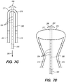
- FIGS. 7A-D illustrate a deflecting mechanism 270 of the ablation system 200, constructed according to one embodiment of the disclosed inventions.
- the deflecting mechanism 270 includes first and second elongate tubular inflation/support members 272 coupled at respective transverse ends of an inflatable deflecting balloon 276.
- Each elongate tubular member 272 has an inner lumen 274 in fluid communication with an interior of the balloon 276 for supplying a fluid and/or gas source for selected inflation of the balloon 276.
- the fluid/gas source may be a syringe, such as syringe 340 depicted in FIG. 5 , filled with a predetermined volume of fluid or gas to adequately inflate the deflecting balloon 276.
- Reverse action of the syringe 340 could similarly be used to deflate the deflecting balloon 276 by withdrawing the fluid/gas from the balloon 276 back into the syringe 340.
- the fluid/gas source 340 may optionally include a pressure sensor to measure the inflation pressure to ensure adequate inflation without over inflation of the deflecting balloon 276. It will be appreciated that in an alternative embodiment, only a single inflation member/lumen 274/272 may be used to inflate (and deflate) the deflecting balloon 276.
- the deflecting mechanism may be constructed similar to applicator head 102, shown in FIGS. 2 and 3A , except that transverse ribbon 138 is replaced with balloon 276 and flexures 124 made from metal or PEEK.
- the deflecting balloon 276 When the deflecting mechanism 270 is disengaged, the deflecting balloon 276 is deflated ( FIGS. 7A and 7C ), so that the energy delivery member 250 of the ablation system 200 is in the delivery configuration ( FIGS. 8A and 9A ). When the deflecting mechanism 270 is engaged, the deflecting balloon 276 is inflated ( FIGS. 7B and 7D ) expanding the energy delivery member 250 into the deployed configuration ( FIGS. 5 , 6 , 8C , and 9C ).
- tissue e.g., endometrium
- the elongate members 272 may be made of polymeric materials, metals and/or alloy materials, such as polyethylene, polyether ether ketone (PEEK), stainless-steel (e.g., 17-7PH), or other suitable biocompatible materials or combinations thereof.
- the deflecting balloon 276 may be made of or otherwise include polymeric materials, such as silicone, urethane polymer, thermoplastic elastomer rubber, santoprene, nylon, polyethylene terephthalate (PET), and other suitable materials or combinations thereof.
- the deflecting balloon 276 is composed of a noncompliant material, such as polyurethane terephthalate (PET), which allows and facilitates inflation of the balloon with the syringe 340 filled with a predetermined volume of fluid (e.g., air).
- the predetermined volume of fluid may correspond to, for example, a preformed volume of balloon 276.
- Having the syringe 340 filled with a predetermined volume of fluid to inflate the noncompliant material balloon 276 reduces the risk of overinflating and overextending of the balloon 276 in its deployed configuration.
- the balloon 276 may be manufactured with standard processing equipment to obtain a balloon having a wall thickness of approximately between 0.0005 inches to 0.005 inches, in a deflated configuration.
- the deflecting balloon 276 is manufactured to comprise an elongate, cylindrical, and/or tubular configuration (e.g., FIGS. 5-9C ). Alternatively, the deflecting balloon 276 may be manufactured to comprise any other suitable configuration. For example, the deflecting balloon 276 may comprise a plurality of bellows or accordion-like configuration (not shown).
- the deflecting balloon 276 composed of non-compliant material is configured to withstand higher inflation pressure without deforming or overextending, than balloons composed of compliant materials.
- the deflecting balloon 276 composed of non-compliant material is inflated with air, which has little thermal capacity, so that the air-inflated deflecting balloon 276 will not draw significant thermal energy from the electrode array 260 when energy is delivered to ablate tissue.
- the air-inflated deflecting balloon 276 composed of noncompliant material is configured to withstand temperatures about 100 °C during ablation procedures, minimizing the risk of bursting or failing of the balloon 276.
- the deflecting balloon 276 may be filled with fluid (i.e., saline), so that the balloon 276 may act as a cooling element drawing thermal energy away from the tissue when energy is delivered by the electrode array 260. It would be understood, that the energy drawn by the balloon filled with fluid, would be taken into consideration by the designer/manufacturer of system 200 and/or by the attending physician or technician during a procedure to determine a proper tissue ablation depth.
- fluid i.e., saline
- the deflecting mechanism 270 may be slideably coupled to a central elongate member 280 to facilitate uniform deployment regardless of uterus width.
- the central elongate member 280 may comprise an actuation mechanism, such as a spring, coil or any other suitable mechanism (not shown) to further assist with the deployment of the deflecting mechanism 270 (e.g., distally translating or pushing the balloon 276).
- the central elongate member 280 has a lumen 282 and a plurality of apertures 284 fluidly coupled to the vacuum source 330 ( FIGS. 7C-D ), so that during the ablation procedure, steam, blood and other fluids are suctioned and removed from a body organ.
- the central elongate member 280 may be slidably coupled to deflecting balloon 276' so that central elongate member 280 can move relative to deflecting balloon 276' in a direction transverse to the other.
- the central elongate member 280 further includes a non-traumatic distal bumper 286.
- the distal bumper 286 may include one or more apertures 284 (not shown) fluidly coupled to the vacuum source 330, so that during the ablation procedure, steam, blood and other fluids are suctioned and removed from a fundus or fundal wall.
- the deflecting balloon 276' has a passageway 277 for allowing passage and longitudinal movement of the central elongate member 280, while allowing the deflecting balloon 276' to be inflated and to maintain the inflated/deployed configuration ( FIG. 7D ).
- the passageway 277 of the deflecting balloon 276' may have an elongated, annular, or "donut hole” like configuration, allowing the central elongate member 280 to be slidably disposed within the passageway 277, so that when the deflecting balloon 276' is inflated and expands/deploys the electrode array 260 (e.g. outwardly) ( FIGS.
- the central elongate member 280 is distally translated to further facilitate uniform deployment of the electrode array 260 (e.g. distally and/or outwardly) regardless of uterus width.
- two or more deflecting balloons 276 may be incorporated and/or used in the deflecting mechanism 270 (not shown), so that the pathways of the central elongate member 280 is defined between the two or more balloons, with no need for a passageway 277 formed in or within the deflecting balloons 276.
- the central elongate member 280 may comprise a plurality of circumferentially disposed protrusions, annular protrusions and/or restriction knots (not shown) disposed proximal to the distal bumper 286, so that the deflecting balloon 276' is disposed between the proximal protrusion(s) and the distal bumper 286.
- the protrusion(s) may further facilitate uniform deployment of the electrode array 260 by pushing the inflated deflecting balloon 276' towards the distal surface 259 of the energy delivery member 250 ( FIG. 9B-C ).
- the protrusion(s) of the central elongated member 280 FIGS.
- the central elongate member 280 may include a plurality of conductive strips (not shown) that are electrically coupled to the electrode array 260 for delivery of RF energy to the endometrial lining tissue.
- the plurality of conductive strips may be woven within the electrode array 260 (not shown). It should be appreciated that the woven conductive strips may be insulated (e.g., non-conductive coating) yet the strips are electrically coupled at some point of the strip to the electrode array 260.
- FIGS. 8A-C illustrate an exemplary method of deployment of the electrode array 260 using the deflecting mechanism 270 of FIGS. 7A-B.
- FIG. 8A depicts the distal portion 216 of the ablation system 200 disposed within the lumen 232 of the outer elongate member 230, having the electrode array 260 in a delivery configuration and the deflecting balloon 276 deflated.
- the deflecting mechanism 270 is engaged by inflating the deflecting balloon 276 ( FIG. 8B ), thereby expanding the electrode array 260 into the deployed configuration ( FIG. 8C ).
- the deflecting balloon 276 includes a preferential fold 278 when deflated ( FIGS. 8A-B ) until the balloon 276 is fully inflated to substantially 100% of its preformed volume ( FIG. 8C ).
- the preferential fold 278 may comprise one or more pleat, bend, crease, crimp, or the like.
- the preferential fold 278 may be formed at the manufacturing stage of the deflecting balloon 276, assisting the deflecting balloon 276 to maintain an insertion profile ( FIG. 8A ).
- preferential fold 278 may be caused by disposing the ablation system 200 into the delivery configuration. In either embodiment, the preferential fold 278 would allow for a consistent inflation pattern of the deflecting balloon to be fully inflated, so that the ablation system 200 transitions into the deployed configuration ( FIGS. 8B-C ).
- the inflated deflecting balloon 276 applies outward spreading force to the elongate members 272 and the electrode array 260 for deployment of the array. Additionally, the deflecting mechanism 270 including the inflated deflecting balloon 276 is configured to maintain the electrode regions separated to avoid contact between the electrodes, during the ablation procedure. The inflated deflecting balloon 276 applies an outward spreading force to the electrode array 260. The spreading force causes the array 260 to take on a shape similar to the uterine cavity whereby the distal region of the electrode array 260 contacts at least a portion of a uterine fundus before vacuum is applied.
- FIGS. 9A-C illustrate an exemplary method of deployment of the electrode array 260 using the deflecting mechanism 270 of FIGS. 7C-D , in accordance with embodiments of the disclosed inventions.
- FIG. 9A illustrates the distal portion 216 of the ablation system 200 disposed within the lumen 232 of the outer elongate member 230, having the electrode array 260 in a delivery configuration including the central elongate member 280, and having the deflecting balloon 276' in a deflated delivery configuration. As shown in FIGS.
- the following acts occur: 1) the outer elongate member 230 is proximately withdrawn; 2) the central elongate member 280 is translated distally so that its distal bumper 286 contacts and pushes the distal surface 259 of the energy delivery member 250, assisting with the deployment of the electrode array 260, further allowing contact of the electrodes with a uterine fundus, and 3) the deflecting mechanism 270 is engaged and inflates the deflecting balloon '276 further expanding the electrode array 260 into the deployed configuration ( FIG. 9C ).
- the deflecting mechanism 270 is distally translated, or the distal translation of the deflecting mechanism 270 occurs simultaneously or consecutively to the proximal withdrawal of the outer elongate member 230.
- the bumper 286 may be coupled, attached or secured to the distal surface 259 of the energy delivery member 250, so that the distal surface 259 is pushed/advanced when the central elongate member 280 is translated distally, and the distal surface 259 is pulled/withdrawn when the central elongate member 280 is translated proximately.
- the outer elongate member 230 withdrawal may be coupled to the actuation of the syringe 340 providing simultaneous withdrawal of the outer elongate member 230, deflecting/actuation and inflation of the deflecting balloons 276 and 276' ( FIGS. 8B-C and 9B-C ).
- a chemical agent may be used for ablating the endometrial ling tissue.
- a treatment system would be less expensive and less complicated to use than an RF (i.e., thermal) tissue ablation system.
- RF i.e., thermal
- a chemical ablation technique using a silver nitrate (AgNO3) paste shows promise for endometrial lining tissue ablations.
- an expandable uterine ablation head similar to the ones disclosed herein, except that the expandable ablation head is coated with a toxic chemical instead of carrying an electrode array. Such a device would allow for controlled ablation occurring only where the coated array is in direct contact with tissue.
- the silver nitrate is first mixed with polyvinyl alcohol (PVA) and de-ionized (DI) water.
- PVA is a water soluble polymer used for controlled drug delivery. By controlling quantity of PVA and silver nitrate, the depth and duration of the ablation can be controlled.
- the external surface material of the expandable ablation head may be dip coated with a silver nitrate/PVA mixture in production before curing.
- the silver nitrate/PVA mixture could be applied to specific regions or sides of the array to provide a more local ablation or maintain an area of un-ablated endometrial lining to prevent adhesions.
- the chemical used to cause the ablation could be gold chloride. Although more costly than silver nitrate, gold chloride may provide for a more rapid ablation. Water soluble polymers could alternatively be used for bonding the ablation chemical to the array.
- the chemical ablation device may incorporate features of NovaSure RF system not specific to electrical energy delivery, including cavity integrity assessment (CIA), vacuum, and variable length and width.
- Deployment of the ablation head within the uterus array may be achieved with a mechanical tensioning mechanism, such as the balloon actuator disclosed and described herein, or an assembly of metallic flexures, such as used in the NovaSure system.
- FIG. 10 illustrates an alternative embodiment of a medical ablation system 200' for RF energy delivery into a target site (e.g., a uterus) of a patient, constructed in accordance with the disclosed inventions.
- a target site e.g., a uterus
- the features and configurations of the ablation system 200' that are the same as the ablation system 200 of FIG. 5 are given the same reference numerals.
- the ablation system 200' includes substantially similar proximal portion 212 and middle portion 214 (not shown) features, functions and configurations of the ablation system 200.
- the ablation system 200' further includes a distal portion 216' having an expandable energy delivery member 250' including an electrode array 260 formed of a stretchable electrically conductive mesh, and a deflecting mechanism 270'.
- the deflecting mechanism 270' includes a pair of elongated polymeric flexures 224 coupled at respective transverse ends to the inflatable deflecting balloon 276, as shown in FIG. 10 .
- the deflecting mechanism or expandable-collapsible support structure 270' includes opposing first and second flexures 224 disposed within the tissue contacting member electrode array 260.
- the flexures 224 have a delivery configuration in which the flexures 224 are in a side-by-side configuration ( FIG. 11A ) aligned with the positioning member or inner elongate member 240.
- the flexures 224 have a deployed configuration in which a distal end of the first flexure 224 is positioned in the first corner portion of the tissue contacting member electrode array 260, and a distal end of the second flexure 224 is positioned in the second corner portion of the tissue contacting member electrode array 260.
- the first and second flexures 224 having arcuate outer surfaces 225 ( FIG. 11B ).
- a non-conductive elongated thread 229 may be operatively coupled to the respective distal ends of the flexures 224; the thread 229 further extends through the inner elongate member 240 ( FIG. 10 ).
- the thread 229 is configured to assist with the disengagement of the deflecting mechanism 270', so that when the deflecting balloon 276 is deflated, the thread 229 is pulled (concurrently and/or subsequently to the deflation of the balloon) bringing the flexures 224 together.
- FIGS. 11A-B illustrate the delivery configuration of the flexures 224 of the deflecting mechanism of the ablation system 200' of FIG. 10 .
- the flexures 224 may be composed of any suitable biocompatible non-conductive material, such as PEEK or the like.
- the first and second flexures 224 each comprises one or more embedded conductors 226, each conductor 226 electrically connected to a respective portion of the tissue contacting member electrode array 260.
- the conductors 226 extend through a respective first and second flexure 224 and further extend through inner elongate member 240, which are operatively connected to an RF generator (not shown).
- the conductors 226 are electrically coupled to the electrode array 260 of the ablation system 200' for delivery of RF energy to the endometrial lining tissue.
- the conductors 226 are embedded in the flexures 224, and each flexures 224 include a respective arcuate (e.g., semi-circular) outer surface 225.
- the arcuate outer surfaces 225 of the first and second flexures 224 together define a cylindrical outer surface ( FIG. 11B ), and the distal ends of the first and second flexures 224 together define a tapered or rounded tip ( FIG. 11A ).
- At least one of the first and second flexures 224 comprises an embedded inflation lumen 223 fluidly coupled to an interior of the balloon 276.
- the inflation lumen 223 is coupled to a fluid and/or gas source for inflation of the balloon 276.
- the deflated balloon 276 is disposed between the distal ends of the first and second flexures 224.
- any of the above described embodiments may incorporate and/or use more than one deflecting mechanism 270 in combination with the electrode array 260. Further, it should be appreciated that any of the above described ablation systems may be used in combination with chemical ablation or any other suitable endometrial ablation system and methods.
Landscapes
- Health & Medical Sciences (AREA)
- Life Sciences & Earth Sciences (AREA)
- Engineering & Computer Science (AREA)
- Heart & Thoracic Surgery (AREA)
- Surgery (AREA)
- Animal Behavior & Ethology (AREA)
- Veterinary Medicine (AREA)
- Public Health (AREA)
- Biomedical Technology (AREA)
- General Health & Medical Sciences (AREA)
- Plasma & Fusion (AREA)
- Physics & Mathematics (AREA)
- Nuclear Medicine, Radiotherapy & Molecular Imaging (AREA)
- Otolaryngology (AREA)
- Medical Informatics (AREA)
- Molecular Biology (AREA)
- Hematology (AREA)
- Anesthesiology (AREA)
- Pulmonology (AREA)
- Biophysics (AREA)
- Child & Adolescent Psychology (AREA)
- Surgical Instruments (AREA)
Claims (15)
- Endometriumgewebe-Behandlungsvorrichtung (200), umfassend:ein längliches Positionierelement (240); undeinen mit einem distalen Ende des Positionierelements (240) gekoppelten Energieapplikator (261),wobei der Energieapplikator (261) ein Gewebekontaktelement (260) und eine unter dem Gewebekontaktelement (260) befindliche ausfahrbare bzw. einziehbare Stützstruktur (270) umfasst,dadurch gekennzeichnet, dassdie ausfahrbare bzw. einziehbare Stützstruktur (270) einen im Wesentlichen unnachgiebigen länglichen Ballon (276, 276') umfasst, der innerhalb des Gewebekontaktelements (260) angeordnet ist, der, wenn er aufgepumpt ist, eine Länge, die im Wesentlichen transversal zu dem Positionierelement (240) ausgerichtet ist, und eine Breite, die im Wesentlichen entlang dem Positionierelement ausgerichtet ist, aufweist,einschließlich eines ersten geschlossenen Endes (276a), das einen entsprechenden ersten Eckabschnitt (262) des Gewebekontaktelements (260) in einem ersten Horn (52) einer Uterushöhle (50) positioniert, und eines zweiten geschlossenen Endes (276b), das einen entsprechenden zweiten Eckabschnitt (263) des Gewebekontaktelements (260) in einem zweiten Horn (53) der Uterushöhle (50) positioniert.
- Endometriumgewebe-Behandlungsvorrichtung (200) nach Anspruch 1, wobei ein Längsabschnitt des Ballons (276), im aufgepumpten Zustand, eine distal gerichtete Fläche (259) des Gewebekontaktelements (260) so positioniert, dass sie mit einer fundalen Wand der Uterushöhle (50) in Kontakt tritt.
- Endometriumgewebe-Behandlungsvorrichtung (200) nach Anspruch 1 oder 2, wobei das Gewebekontaktelement (260) feuchtigkeitsdurchlässig ist.
- Endometriumgewebe-Behandlungsvorrichtung (200) nach einem der Ansprüche 1-3, weiter eine längliche hohle Abgabehülse (230) umfassend, die einen distalen Abschnitt aufweist, der zur transcervicalen Anordnung in der Uterushöhle (50) eingerichtet ist, wobei die Abgabehülse (230) ein Lumen (232) und ein offenes distales Ende in Kommunikation mit dem Abgabehülsenlumen aufweist,
wobei das jeweilige Positionierungselement (240) und der Energieapplikator (261) verschiebbar in dem Abgabehülsenlumen (232) angeordnet sind, sodass sich der Energieapplikator (261) verschiebbar bewegt zwischen
einer eingeklappten Konfiguration, worin der Energieapplikator (261) mindestens teilweise durch das offene distale Ende der Abgabehülse (230) und in das Abgabehülsenlumen (232) eingezogen ist, und
einer ausgefahrenen Konfiguration, worin der Energieapplikator (261) aus dem offenen distalen Ende der Abgabehülse (230) ausgefahren ist und mindestens teilweise selbstexpandiert ist, um sich an die Uterushöhle (50) anzupassen. - Endometriumgewebe-Behandlungsvorrichtung (200) nach Anspruch 4, wobei die Abgabehülse (230) und das Positionierelement (240) wirksam mit einem Stellglied gekoppelt sind, welches das Positionierelement (240) bezüglich der Abgabehülse (230) bewegt, um dadurch den Energieapplikator (261) zwischen der eingeklappten Konfiguration und der ausgefahrenen Konfiguration zu bewegen.
- Endometriumgewebe-Behandlungsvorrichtung (200) nach Anspruch 4, wobei das Stellglied einen griffartigen Handgriff (220) umfasst, der durch Zusammendrücken eines Paars schwenkbar verbundener Griffelemente betätigt wird.
- Endometriumgewebe-Behandlungsvorrichtung (200) nach einem der Ansprüche 1-6, weiter mindestens ein Aufpumpelement (272) umfassend, das ein Aufpumplumen (274) aufweist, das fluidisch mit einem Inneren des Ballons (276,276') gekoppelt ist, wobei ein proximales Ende des betreffenden Aufpumpelements (272) dazu eingerichtet ist, um das jeweilige Aufpumplumen (274) fluidisch mit einer Quelle von Aufpumpmedium zu koppeln.
- Endometriumgewebe-Behandlungsvorrichtung (200, 200') nach einem der Ansprüche 1-7, weiter ein längliches Spannelement (280) umfassend, das in Bezug zu dem Positionierelement (240) bewegbar ist, wobei das Spannelement (280) ein distales Ende aufweist, das an einem Punkt ungefähr auf halber Länge des Ballons (276') an dem Ballon (276') befestigt ist.
- Endometriumgewebe-Behandlungsvorrichtung (200) nach Anspruch 8, wobei das distale Ende des Spannelements (280) ein Ringelement umfasst oder damit verbunden ist, das den Ballon (276') an dem Punkt ungefähr auf halber Länge des Ballons (276') mindestens teilweise in Umfangsrichtung umgibt.
- Endometriumgewebe-Behandlungsvorrichtung (200) nach einem der Ansprüche 1-9 in Kombination mit Anspruch 4, weiter ein Aspirationslumen umfassend, das sich durch das Positionierelement (240) erstreckt und ein offenes distales Ende aufweist, das sich innerhalb der Stützstruktur (270) des Energieapplikators (261) befindet, wenn sich der Energieapplikator (261) in der ausgefahrenen Konfiguration befindet.
- Endometriumgewebe-Behandlungsvorrichtung (200) nach Anspruch 1, wobei die Stützstruktur (270) weiter ein einander gegenüberliegendes erstes und zweites Biegeelement (224) umfasst, die in dem Gewebekontaktelement (260) angeordnet sind, wobei die Biegeelemente eine Abgabekonfiguration, worin sich die Biegeelemente in einer Seite-an-Seite-Konfiguration in Ausrichtung mit dem Positionierelement befinden, und eine Einsatzkonfiguration, worin ein distales Ende des ersten Biegeelements in dem ersten Eckabschnitt des Gewebekontaktelements positioniert ist und ein distales Ende des zweiten Biegeelements in dem zweiten Eckabschnitt des Gewebekontaktelements positioniert ist, aufweisen, wobei das erste und das zweite Biegeelement bogenförmige Außenflächen aufweisen.
- Endometriumgewebe-Behandlungsvorrichtung (200) nach Anspruch 11, wobei in der Seite-an-Seite-Abgabekonfiguration die bogenförmigen Außenflächen des ersten und des zweiten Biegeelements zusammen eine zylindrische Außenfläche definieren.
- Endometriumgewebe-Behandlungsvorrichtung (200) nach Anspruch 11 oder 12, wobei in der Seite-an-Seite-Abgabekonfiguration die distalen Enden des ersten und des zweiten Biegeelements zusammen eine verjüngte oder abgerundete Spitze definieren.
- Endometriumgewebe-Behandlungsvorrichtung nach einem von Anspruch 11-13, wobei das erste und das zweite Biegeelement (224) jedes einen oder mehrere eingebettete Leiter (226) umfassen, wobei jeder Leiter (226) elektrisch mit einem jeweiligen Abschnitt des Gewebekontaktelements (260) verbunden ist.
- Endometriumgewebe-Behandlungsvorrichtung (200) nach einem der Ansprüche 11-14, wobei mindestens eines des ersten und des zweiten Biegeelements (224) ein eingebettetes Aufpumplumen (223) umfasst, das fluidisch mit einem Inneren des Ballons (276) gekoppelt ist.
Applications Claiming Priority (2)
| Application Number | Priority Date | Filing Date | Title |
|---|---|---|---|
| US201462061081P | 2014-10-07 | 2014-10-07 | |
| PCT/US2015/054284 WO2016057545A1 (en) | 2014-10-07 | 2015-10-06 | Endometrial lining tissue treatment device |
Publications (2)
| Publication Number | Publication Date |
|---|---|
| EP3203922A1 EP3203922A1 (de) | 2017-08-16 |
| EP3203922B1 true EP3203922B1 (de) | 2018-04-18 |
Family
ID=54330096
Family Applications (1)
| Application Number | Title | Priority Date | Filing Date |
|---|---|---|---|
| EP15781558.0A Active EP3203922B1 (de) | 2014-10-07 | 2015-10-06 | Behandlungsvorrichtung für endometriumschleimhaut |
Country Status (3)
| Country | Link |
|---|---|
| US (1) | US10117710B2 (de) |
| EP (1) | EP3203922B1 (de) |
| WO (1) | WO2016057545A1 (de) |
Families Citing this family (8)
| Publication number | Priority date | Publication date | Assignee | Title |
|---|---|---|---|---|
| WO2018140892A1 (en) * | 2017-01-27 | 2018-08-02 | Minerva Surgical, Inc. | Systems and methods for evaluating the integrity of a uterine cavity |
| US11020045B2 (en) | 2017-03-17 | 2021-06-01 | Minerva Surgical, Inc. | Systems and methods for evaluating the integrity of a uterine cavity |
| US10213151B2 (en) | 2017-01-27 | 2019-02-26 | Minerva Surgical, Inc. | Systems and methods for evaluating the integrity of a uterine cavity |
| CN107736910B (zh) * | 2017-11-15 | 2024-11-29 | 蔡华蕾 | 一种易放置式多功能子宫腔弹性球囊支架 |
| CN109528276B (zh) * | 2018-12-18 | 2021-03-19 | 莒县人民医院 | 一种妇产科用紧急助产智能装置 |
| EP3905963B1 (de) * | 2018-12-31 | 2025-07-30 | Vivasure Medical Limited | Verstellbare gefässverschlussvorrichtung |
| US11890299B2 (en) * | 2019-06-27 | 2024-02-06 | Hologic, Inc. | Ablation agent and methods of use |
| CN114515211B (zh) * | 2022-03-15 | 2026-02-10 | 诺一迈尔(苏州)医学科技有限公司 | 一种促进子宫内膜再生的可降解生物膜的输送装置 |
Citations (2)
| Publication number | Priority date | Publication date | Assignee | Title |
|---|---|---|---|---|
| US4160446A (en) * | 1977-08-12 | 1979-07-10 | Abcor, Inc. | Apparatus for and method of sterilization by the delivery of tubal-occluding polymer |
| US6245067B1 (en) * | 1997-04-16 | 2001-06-12 | Irvine Biomedical, Inc. | Ablation device and methods having perpendicular electrodes |
Family Cites Families (13)
| Publication number | Priority date | Publication date | Assignee | Title |
|---|---|---|---|---|
| US7604633B2 (en) * | 1996-04-12 | 2009-10-20 | Cytyc Corporation | Moisture transport system for contact electrocoagulation |
| US6813520B2 (en) | 1996-04-12 | 2004-11-02 | Novacept | Method for ablating and/or coagulating tissue using moisture transport |
| US6508815B1 (en) | 1998-05-08 | 2003-01-21 | Novacept | Radio-frequency generator for powering an ablation device |
| US7500973B2 (en) * | 2003-12-22 | 2009-03-10 | Ams Research Corporation | Cryosurgical devices and methods for endometrial ablation |
| US7625368B2 (en) * | 2005-10-17 | 2009-12-01 | Galil Medical Ltd. | Endometrial ablation device and method |
| US9259233B2 (en) * | 2007-04-06 | 2016-02-16 | Hologic, Inc. | Method and device for distending a gynecological cavity |
| US20090125010A1 (en) * | 2007-07-06 | 2009-05-14 | Sharkey Hugh R | Uterine Therapy Device and Method |
| WO2009149108A1 (en) * | 2008-06-02 | 2009-12-10 | Loma Vista Medical, Inc. | Inflatable medical devices |
| WO2010104720A1 (en) * | 2009-03-09 | 2010-09-16 | Cytyc Corporation | Ablation device with suction capability |
| US9289257B2 (en) | 2009-11-13 | 2016-03-22 | Minerva Surgical, Inc. | Methods and systems for endometrial ablation utilizing radio frequency |
| US8936592B2 (en) | 2010-06-03 | 2015-01-20 | Ams Research Corporation | Laser tissue ablation system |
| US20120265197A1 (en) | 2010-10-19 | 2012-10-18 | Minerva Surgical, Inc. | Systems and methods for endometrial ablation |
| US9131980B2 (en) * | 2011-12-19 | 2015-09-15 | Medtronic Advanced Energy Llc | Electrosurgical devices |
-
2015
- 2015-10-06 EP EP15781558.0A patent/EP3203922B1/de active Active
- 2015-10-06 US US14/876,515 patent/US10117710B2/en active Active
- 2015-10-06 WO PCT/US2015/054284 patent/WO2016057545A1/en not_active Ceased
Patent Citations (2)
| Publication number | Priority date | Publication date | Assignee | Title |
|---|---|---|---|---|
| US4160446A (en) * | 1977-08-12 | 1979-07-10 | Abcor, Inc. | Apparatus for and method of sterilization by the delivery of tubal-occluding polymer |
| US6245067B1 (en) * | 1997-04-16 | 2001-06-12 | Irvine Biomedical, Inc. | Ablation device and methods having perpendicular electrodes |
Also Published As
| Publication number | Publication date |
|---|---|
| US20160095648A1 (en) | 2016-04-07 |
| WO2016057545A1 (en) | 2016-04-14 |
| US10117710B2 (en) | 2018-11-06 |
| EP3203922A1 (de) | 2017-08-16 |
Similar Documents
| Publication | Publication Date | Title |
|---|---|---|
| EP3203922B1 (de) | Behandlungsvorrichtung für endometriumschleimhaut | |
| US12207844B2 (en) | Systems and methods for endometrial ablation | |
| US12178499B2 (en) | Catheter | |
| US9572619B2 (en) | Medical device for treating airways and related methods of use | |
| EP1415607B1 (de) | Feuchtigkeitsförderungssystem für Berührungselektrokoagulation | |
| US10052150B2 (en) | Device for endometrial ablation having an expandable seal for a cervical canal | |
| WO2014158727A1 (en) | Steerable ablation device with linear ionically conductive balloon | |
| US20050085880A1 (en) | Moisture transport system for contact electrocoagulation | |
| US20100228239A1 (en) | Ablation device with suction capability | |
| US20130110106A1 (en) | Expandable structure for off-wall ablation electrode | |
| EP3030183B1 (de) | Elektrochirurgische vorrichtung | |
| CN104159536A (zh) | 用于神经调制的离壁和接触电极装置以及方法 | |
| CN103987336A (zh) | 具有多种消融模式的消融装置 | |
| EP4140429A1 (de) | Korbkatheter mit poröser hülle | |
| US9259262B2 (en) | Systems and methods for endometrial ablation | |
| CN116264986A (zh) | 具有缓冲多孔护套盖的篮形导管 | |
| US20190307499A1 (en) | Ablation device having a sheath with a dilatable member for fixation and/or support of an ablation applicator, and method of operating an ablation device | |
| AU2021334354A1 (en) | Expandable electroporation devices and methods of use | |
| CN117898821A (zh) | 具有多孔护套的篮形导管 |
Legal Events
| Date | Code | Title | Description |
|---|---|---|---|
| STAA | Information on the status of an ep patent application or granted ep patent |
Free format text: STATUS: THE INTERNATIONAL PUBLICATION HAS BEEN MADE |
|
| PUAI | Public reference made under article 153(3) epc to a published international application that has entered the european phase |
Free format text: ORIGINAL CODE: 0009012 |
|
| STAA | Information on the status of an ep patent application or granted ep patent |
Free format text: STATUS: REQUEST FOR EXAMINATION WAS MADE |
|
| 17P | Request for examination filed |
Effective date: 20170504 |
|
| AK | Designated contracting states |
Kind code of ref document: A1 Designated state(s): AL AT BE BG CH CY CZ DE DK EE ES FI FR GB GR HR HU IE IS IT LI LT LU LV MC MK MT NL NO PL PT RO RS SE SI SK SM TR |
|
| AX | Request for extension of the european patent |
Extension state: BA ME |
|
| REG | Reference to a national code |
Ref country code: DE Ref legal event code: R079 Ref document number: 602015010230 Country of ref document: DE Free format text: PREVIOUS MAIN CLASS: A61B0018140000 Ipc: A61M0025100000 |
|
| GRAP | Despatch of communication of intention to grant a patent |
Free format text: ORIGINAL CODE: EPIDOSNIGR1 |
|
| STAA | Information on the status of an ep patent application or granted ep patent |
Free format text: STATUS: GRANT OF PATENT IS INTENDED |
|
| RIC1 | Information provided on ipc code assigned before grant |
Ipc: A61B 18/14 20060101ALI20171019BHEP Ipc: A61M 25/10 20130101AFI20171019BHEP Ipc: A61B 17/42 20060101ALN20171019BHEP |
|
| DAV | Request for validation of the european patent (deleted) | ||
| DAX | Request for extension of the european patent (deleted) | ||
| INTG | Intention to grant announced |
Effective date: 20171102 |
|
| GRAS | Grant fee paid |
Free format text: ORIGINAL CODE: EPIDOSNIGR3 |
|
| GRAA | (expected) grant |
Free format text: ORIGINAL CODE: 0009210 |
|
| STAA | Information on the status of an ep patent application or granted ep patent |
Free format text: STATUS: THE PATENT HAS BEEN GRANTED |
|
| AK | Designated contracting states |
Kind code of ref document: B1 Designated state(s): AL AT BE BG CH CY CZ DE DK EE ES FI FR GB GR HR HU IE IS IT LI LT LU LV MC MK MT NL NO PL PT RO RS SE SI SK SM TR |
|
| REG | Reference to a national code |
Ref country code: GB Ref legal event code: FG4D |
|
| REG | Reference to a national code |
Ref country code: CH Ref legal event code: EP |
|
| REG | Reference to a national code |
Ref country code: AT Ref legal event code: REF Ref document number: 989794 Country of ref document: AT Kind code of ref document: T Effective date: 20180515 |
|
| REG | Reference to a national code |
Ref country code: IE Ref legal event code: FG4D |
|
| REG | Reference to a national code |
Ref country code: DE Ref legal event code: R096 Ref document number: 602015010230 Country of ref document: DE |
|
| REG | Reference to a national code |
Ref country code: NL Ref legal event code: FP |
|
| REG | Reference to a national code |
Ref country code: LT Ref legal event code: MG4D |
|
| PG25 | Lapsed in a contracting state [announced via postgrant information from national office to epo] |
Ref country code: NO Free format text: LAPSE BECAUSE OF FAILURE TO SUBMIT A TRANSLATION OF THE DESCRIPTION OR TO PAY THE FEE WITHIN THE PRESCRIBED TIME-LIMIT Effective date: 20180718 Ref country code: AL Free format text: LAPSE BECAUSE OF FAILURE TO SUBMIT A TRANSLATION OF THE DESCRIPTION OR TO PAY THE FEE WITHIN THE PRESCRIBED TIME-LIMIT Effective date: 20180418 Ref country code: BG Free format text: LAPSE BECAUSE OF FAILURE TO SUBMIT A TRANSLATION OF THE DESCRIPTION OR TO PAY THE FEE WITHIN THE PRESCRIBED TIME-LIMIT Effective date: 20180718 Ref country code: FI Free format text: LAPSE BECAUSE OF FAILURE TO SUBMIT A TRANSLATION OF THE DESCRIPTION OR TO PAY THE FEE WITHIN THE PRESCRIBED TIME-LIMIT Effective date: 20180418 Ref country code: SE Free format text: LAPSE BECAUSE OF FAILURE TO SUBMIT A TRANSLATION OF THE DESCRIPTION OR TO PAY THE FEE WITHIN THE PRESCRIBED TIME-LIMIT Effective date: 20180418 Ref country code: PL Free format text: LAPSE BECAUSE OF FAILURE TO SUBMIT A TRANSLATION OF THE DESCRIPTION OR TO PAY THE FEE WITHIN THE PRESCRIBED TIME-LIMIT Effective date: 20180418 Ref country code: LT Free format text: LAPSE BECAUSE OF FAILURE TO SUBMIT A TRANSLATION OF THE DESCRIPTION OR TO PAY THE FEE WITHIN THE PRESCRIBED TIME-LIMIT Effective date: 20180418 Ref country code: ES Free format text: LAPSE BECAUSE OF FAILURE TO SUBMIT A TRANSLATION OF THE DESCRIPTION OR TO PAY THE FEE WITHIN THE PRESCRIBED TIME-LIMIT Effective date: 20180418 |
|
| PG25 | Lapsed in a contracting state [announced via postgrant information from national office to epo] |
Ref country code: RS Free format text: LAPSE BECAUSE OF FAILURE TO SUBMIT A TRANSLATION OF THE DESCRIPTION OR TO PAY THE FEE WITHIN THE PRESCRIBED TIME-LIMIT Effective date: 20180418 Ref country code: HR Free format text: LAPSE BECAUSE OF FAILURE TO SUBMIT A TRANSLATION OF THE DESCRIPTION OR TO PAY THE FEE WITHIN THE PRESCRIBED TIME-LIMIT Effective date: 20180418 Ref country code: LV Free format text: LAPSE BECAUSE OF FAILURE TO SUBMIT A TRANSLATION OF THE DESCRIPTION OR TO PAY THE FEE WITHIN THE PRESCRIBED TIME-LIMIT Effective date: 20180418 Ref country code: GR Free format text: LAPSE BECAUSE OF FAILURE TO SUBMIT A TRANSLATION OF THE DESCRIPTION OR TO PAY THE FEE WITHIN THE PRESCRIBED TIME-LIMIT Effective date: 20180719 |
|
| REG | Reference to a national code |
Ref country code: AT Ref legal event code: MK05 Ref document number: 989794 Country of ref document: AT Kind code of ref document: T Effective date: 20180418 |
|
| PG25 | Lapsed in a contracting state [announced via postgrant information from national office to epo] |
Ref country code: PT Free format text: LAPSE BECAUSE OF FAILURE TO SUBMIT A TRANSLATION OF THE DESCRIPTION OR TO PAY THE FEE WITHIN THE PRESCRIBED TIME-LIMIT Effective date: 20180820 |
|
| REG | Reference to a national code |
Ref country code: DE Ref legal event code: R097 Ref document number: 602015010230 Country of ref document: DE |
|
| PG25 | Lapsed in a contracting state [announced via postgrant information from national office to epo] |
Ref country code: EE Free format text: LAPSE BECAUSE OF FAILURE TO SUBMIT A TRANSLATION OF THE DESCRIPTION OR TO PAY THE FEE WITHIN THE PRESCRIBED TIME-LIMIT Effective date: 20180418 Ref country code: AT Free format text: LAPSE BECAUSE OF FAILURE TO SUBMIT A TRANSLATION OF THE DESCRIPTION OR TO PAY THE FEE WITHIN THE PRESCRIBED TIME-LIMIT Effective date: 20180418 Ref country code: CZ Free format text: LAPSE BECAUSE OF FAILURE TO SUBMIT A TRANSLATION OF THE DESCRIPTION OR TO PAY THE FEE WITHIN THE PRESCRIBED TIME-LIMIT Effective date: 20180418 Ref country code: RO Free format text: LAPSE BECAUSE OF FAILURE TO SUBMIT A TRANSLATION OF THE DESCRIPTION OR TO PAY THE FEE WITHIN THE PRESCRIBED TIME-LIMIT Effective date: 20180418 Ref country code: DK Free format text: LAPSE BECAUSE OF FAILURE TO SUBMIT A TRANSLATION OF THE DESCRIPTION OR TO PAY THE FEE WITHIN THE PRESCRIBED TIME-LIMIT Effective date: 20180418 Ref country code: SK Free format text: LAPSE BECAUSE OF FAILURE TO SUBMIT A TRANSLATION OF THE DESCRIPTION OR TO PAY THE FEE WITHIN THE PRESCRIBED TIME-LIMIT Effective date: 20180418 |
|
| PLBE | No opposition filed within time limit |
Free format text: ORIGINAL CODE: 0009261 |
|
| STAA | Information on the status of an ep patent application or granted ep patent |
Free format text: STATUS: NO OPPOSITION FILED WITHIN TIME LIMIT |
|
| PG25 | Lapsed in a contracting state [announced via postgrant information from national office to epo] |
Ref country code: IT Free format text: LAPSE BECAUSE OF FAILURE TO SUBMIT A TRANSLATION OF THE DESCRIPTION OR TO PAY THE FEE WITHIN THE PRESCRIBED TIME-LIMIT Effective date: 20180418 Ref country code: SM Free format text: LAPSE BECAUSE OF FAILURE TO SUBMIT A TRANSLATION OF THE DESCRIPTION OR TO PAY THE FEE WITHIN THE PRESCRIBED TIME-LIMIT Effective date: 20180418 |
|
| 26N | No opposition filed |
Effective date: 20190121 |
|
| REG | Reference to a national code |
Ref country code: DE Ref legal event code: R119 Ref document number: 602015010230 Country of ref document: DE |
|
| REG | Reference to a national code |
Ref country code: CH Ref legal event code: PL |
|
| REG | Reference to a national code |
Ref country code: BE Ref legal event code: MM Effective date: 20181031 |
|
| PG25 | Lapsed in a contracting state [announced via postgrant information from national office to epo] |
Ref country code: LU Free format text: LAPSE BECAUSE OF NON-PAYMENT OF DUE FEES Effective date: 20181006 Ref country code: MC Free format text: LAPSE BECAUSE OF FAILURE TO SUBMIT A TRANSLATION OF THE DESCRIPTION OR TO PAY THE FEE WITHIN THE PRESCRIBED TIME-LIMIT Effective date: 20180418 |
|
| REG | Reference to a national code |
Ref country code: IE Ref legal event code: MM4A |
|
| PG25 | Lapsed in a contracting state [announced via postgrant information from national office to epo] |
Ref country code: DE Free format text: LAPSE BECAUSE OF NON-PAYMENT OF DUE FEES Effective date: 20190501 |
|
| PG25 | Lapsed in a contracting state [announced via postgrant information from national office to epo] |
Ref country code: LI Free format text: LAPSE BECAUSE OF NON-PAYMENT OF DUE FEES Effective date: 20181031 Ref country code: FR Free format text: LAPSE BECAUSE OF NON-PAYMENT OF DUE FEES Effective date: 20181031 Ref country code: CH Free format text: LAPSE BECAUSE OF NON-PAYMENT OF DUE FEES Effective date: 20181031 Ref country code: BE Free format text: LAPSE BECAUSE OF NON-PAYMENT OF DUE FEES Effective date: 20181031 |
|
| PG25 | Lapsed in a contracting state [announced via postgrant information from national office to epo] |
Ref country code: IE Free format text: LAPSE BECAUSE OF NON-PAYMENT OF DUE FEES Effective date: 20181006 |
|
| PG25 | Lapsed in a contracting state [announced via postgrant information from national office to epo] |
Ref country code: MT Free format text: LAPSE BECAUSE OF NON-PAYMENT OF DUE FEES Effective date: 20181006 |
|
| PG25 | Lapsed in a contracting state [announced via postgrant information from national office to epo] |
Ref country code: TR Free format text: LAPSE BECAUSE OF FAILURE TO SUBMIT A TRANSLATION OF THE DESCRIPTION OR TO PAY THE FEE WITHIN THE PRESCRIBED TIME-LIMIT Effective date: 20180418 |
|
| PG25 | Lapsed in a contracting state [announced via postgrant information from national office to epo] |
Ref country code: HU Free format text: LAPSE BECAUSE OF FAILURE TO SUBMIT A TRANSLATION OF THE DESCRIPTION OR TO PAY THE FEE WITHIN THE PRESCRIBED TIME-LIMIT; INVALID AB INITIO Effective date: 20151006 Ref country code: CY Free format text: LAPSE BECAUSE OF FAILURE TO SUBMIT A TRANSLATION OF THE DESCRIPTION OR TO PAY THE FEE WITHIN THE PRESCRIBED TIME-LIMIT Effective date: 20180418 Ref country code: MK Free format text: LAPSE BECAUSE OF NON-PAYMENT OF DUE FEES Effective date: 20180418 |
|
| PG25 | Lapsed in a contracting state [announced via postgrant information from national office to epo] |
Ref country code: IS Free format text: LAPSE BECAUSE OF FAILURE TO SUBMIT A TRANSLATION OF THE DESCRIPTION OR TO PAY THE FEE WITHIN THE PRESCRIBED TIME-LIMIT Effective date: 20180818 |
|
| PG25 | Lapsed in a contracting state [announced via postgrant information from national office to epo] |
Ref country code: SI Free format text: LAPSE BECAUSE OF NON-PAYMENT OF DUE FEES Effective date: 20181006 |
|
| PGFP | Annual fee paid to national office [announced via postgrant information from national office to epo] |
Ref country code: NL Payment date: 20251026 Year of fee payment: 11 |
|
| PGFP | Annual fee paid to national office [announced via postgrant information from national office to epo] |
Ref country code: GB Payment date: 20251027 Year of fee payment: 11 |