EP3203701B1 - Method of controlling a real-time conference session, a computer program product causing a computer to execute the method, and a communication system for controlling the real-time conference session - Google Patents
Method of controlling a real-time conference session, a computer program product causing a computer to execute the method, and a communication system for controlling the real-time conference session Download PDFInfo
- Publication number
- EP3203701B1 EP3203701B1 EP16154347.5A EP16154347A EP3203701B1 EP 3203701 B1 EP3203701 B1 EP 3203701B1 EP 16154347 A EP16154347 A EP 16154347A EP 3203701 B1 EP3203701 B1 EP 3203701B1
- Authority
- EP
- European Patent Office
- Prior art keywords
- user
- duration
- time
- data
- recording
- Prior art date
- Legal status (The legal status is an assumption and is not a legal conclusion. Google has not performed a legal analysis and makes no representation as to the accuracy of the status listed.)
- Active
Links
- 238000004891 communication Methods 0.000 title claims description 86
- 238000000034 method Methods 0.000 title claims description 29
- 238000004590 computer program Methods 0.000 title claims description 6
- 238000001514 detection method Methods 0.000 claims description 22
- 230000000694 effects Effects 0.000 claims description 22
- 230000004044 response Effects 0.000 claims description 18
- 230000001960 triggered effect Effects 0.000 claims description 3
- 230000003213 activating effect Effects 0.000 claims description 2
- 238000011144 upstream manufacturing Methods 0.000 description 9
- 230000005540 biological transmission Effects 0.000 description 7
- 230000003111 delayed effect Effects 0.000 description 5
- 230000001413 cellular effect Effects 0.000 description 2
- 230000007246 mechanism Effects 0.000 description 2
- 241001122315 Polites Species 0.000 description 1
- 230000008859 change Effects 0.000 description 1
- 230000000295 complement effect Effects 0.000 description 1
- 239000003636 conditioned culture medium Substances 0.000 description 1
- 230000001934 delay Effects 0.000 description 1
- 230000001419 dependent effect Effects 0.000 description 1
- 238000010586 diagram Methods 0.000 description 1
- 230000006870 function Effects 0.000 description 1
- 230000003993 interaction Effects 0.000 description 1
- 239000002609 medium Substances 0.000 description 1
- 239000000203 mixture Substances 0.000 description 1
- 230000008569 process Effects 0.000 description 1
- 230000003252 repetitive effect Effects 0.000 description 1
Images


Classifications
-
- H—ELECTRICITY
- H04—ELECTRIC COMMUNICATION TECHNIQUE
- H04N—PICTORIAL COMMUNICATION, e.g. TELEVISION
- H04N7/00—Television systems
- H04N7/14—Systems for two-way working
- H04N7/15—Conference systems
-
- H—ELECTRICITY
- H04—ELECTRIC COMMUNICATION TECHNIQUE
- H04L—TRANSMISSION OF DIGITAL INFORMATION, e.g. TELEGRAPHIC COMMUNICATION
- H04L12/00—Data switching networks
- H04L12/02—Details
- H04L12/16—Arrangements for providing special services to substations
- H04L12/18—Arrangements for providing special services to substations for broadcast or conference, e.g. multicast
- H04L12/1813—Arrangements for providing special services to substations for broadcast or conference, e.g. multicast for computer conferences, e.g. chat rooms
- H04L12/1831—Tracking arrangements for later retrieval, e.g. recording contents, participants activities or behavior, network status
-
- H—ELECTRICITY
- H04—ELECTRIC COMMUNICATION TECHNIQUE
- H04L—TRANSMISSION OF DIGITAL INFORMATION, e.g. TELEGRAPHIC COMMUNICATION
- H04L65/00—Network arrangements, protocols or services for supporting real-time applications in data packet communication
- H04L65/60—Network streaming of media packets
- H04L65/75—Media network packet handling
- H04L65/762—Media network packet handling at the source
-
- H—ELECTRICITY
- H04—ELECTRIC COMMUNICATION TECHNIQUE
- H04L—TRANSMISSION OF DIGITAL INFORMATION, e.g. TELEGRAPHIC COMMUNICATION
- H04L65/00—Network arrangements, protocols or services for supporting real-time applications in data packet communication
- H04L65/10—Architectures or entities
- H04L65/102—Gateways
- H04L65/1023—Media gateways
-
- H—ELECTRICITY
- H04—ELECTRIC COMMUNICATION TECHNIQUE
- H04L—TRANSMISSION OF DIGITAL INFORMATION, e.g. TELEGRAPHIC COMMUNICATION
- H04L65/00—Network arrangements, protocols or services for supporting real-time applications in data packet communication
- H04L65/1066—Session management
- H04L65/1083—In-session procedures
- H04L65/1094—Inter-user-equipment sessions transfer or sharing
-
- H—ELECTRICITY
- H04—ELECTRIC COMMUNICATION TECHNIQUE
- H04L—TRANSMISSION OF DIGITAL INFORMATION, e.g. TELEGRAPHIC COMMUNICATION
- H04L65/00—Network arrangements, protocols or services for supporting real-time applications in data packet communication
- H04L65/40—Support for services or applications
- H04L65/403—Arrangements for multi-party communication, e.g. for conferences
- H04L65/4038—Arrangements for multi-party communication, e.g. for conferences with floor control
-
- H—ELECTRICITY
- H04—ELECTRIC COMMUNICATION TECHNIQUE
- H04M—TELEPHONIC COMMUNICATION
- H04M3/00—Automatic or semi-automatic exchanges
- H04M3/42—Systems providing special services or facilities to subscribers
- H04M3/56—Arrangements for connecting several subscribers to a common circuit, i.e. affording conference facilities
- H04M3/563—User guidance or feature selection
- H04M3/566—User guidance or feature selection relating to a participants right to speak
-
- H—ELECTRICITY
- H04—ELECTRIC COMMUNICATION TECHNIQUE
- H04M—TELEPHONIC COMMUNICATION
- H04M3/00—Automatic or semi-automatic exchanges
- H04M3/42—Systems providing special services or facilities to subscribers
- H04M3/56—Arrangements for connecting several subscribers to a common circuit, i.e. affording conference facilities
- H04M3/567—Multimedia conference systems
-
- H—ELECTRICITY
- H04—ELECTRIC COMMUNICATION TECHNIQUE
- H04M—TELEPHONIC COMMUNICATION
- H04M3/00—Automatic or semi-automatic exchanges
- H04M3/42—Systems providing special services or facilities to subscribers
- H04M3/56—Arrangements for connecting several subscribers to a common circuit, i.e. affording conference facilities
- H04M3/568—Arrangements for connecting several subscribers to a common circuit, i.e. affording conference facilities audio processing specific to telephonic conferencing, e.g. spatial distribution, mixing of participants
- H04M3/569—Arrangements for connecting several subscribers to a common circuit, i.e. affording conference facilities audio processing specific to telephonic conferencing, e.g. spatial distribution, mixing of participants using the instant speaker's algorithm
-
- H—ELECTRICITY
- H04—ELECTRIC COMMUNICATION TECHNIQUE
- H04N—PICTORIAL COMMUNICATION, e.g. TELEVISION
- H04N7/00—Television systems
- H04N7/14—Systems for two-way working
- H04N7/15—Conference systems
- H04N7/155—Conference systems involving storage of or access to video conference sessions
-
- H—ELECTRICITY
- H04—ELECTRIC COMMUNICATION TECHNIQUE
- H04M—TELEPHONIC COMMUNICATION
- H04M2203/00—Aspects of automatic or semi-automatic exchanges
- H04M2203/30—Aspects of automatic or semi-automatic exchanges related to audio recordings in general
- H04M2203/305—Recording playback features, e.g. increased speed
Definitions
- the invention relates to a method of controlling a real-time conference session.
- the invention further relates to a computer program product causing a computer to execute the method, and a communication system for controlling the real-time conference session.
- US 2008/0137558 discloses a method including a receiving input indicating that an endpoint is dropping out of a real-time mode of attending an ongoing conference session.
- a modern conference session can be established by a mixing unit in the form of a conference bridge or Media Streamer.
- the Media Streamer executes an application for controlling of a conference which can be defined as a program, in particular a computer program or application software that allows an administrator to control the conference.
- the application for controlling a conference is running on a computer, the application is able to provide a mixture of speech signals from participants, also called users, of the conference.
- the application for controlling the conference can be installed on a personal computer, abbreviated to PC, and/or run on the PC.
- PC is also referred to as the Media Streamer, a media server or application server.
- the application for controlling the conference itself is called Media Server.
- Media Server the application for controlling the conference itself is called Media Server.
- the term “Media Streamer”, which is also called “conference server”, is equally used for execution of the application software for controlling the conference in the form of software, and in a form of this application in hardware.
- the Media Streamer is set up to receive as a server from each of the communication terminals of the conference participants the respective audio/video signals and to transmit the mixed audio/video signals to communication terminals of the conference participants.
- a communication terminal of a participant may act a telephone unit, an IP Phone (IP: internet Protocol) or a PC client, wherein another communication terminal, such as a mobile telephone or another server, is possible.
- IP internet Protocol
- a conference in which at least two participants of the conference are not resident at a same place/location such that they cannot communicate with each other without the use of technical means.
- the communication of the participants will rather be executed via the mixing unit by mixing the voice signals of the participants, wherein said conference can be configured for example as a teleconference or videoconference.
- participants communicate only by exchange of speech regardless of how the voice signals of the participants are transferred. Therefore, both a teleconference over a landline and a teleconference in which one or more participants communicate with each other over a cellular network are called teleconference.
- a conference in the form of a video conference is possible with image signals of the participants being transmitted in real-time to other participants in addition to the exchange of voice signals of the participants.
- a conference is also meant to comprise an application sharing wherein other media are to be exchanged between the participants of the conference in addition to the exchange of voice and video data of the participants, for example in the form of a transfer of data between the participants.
- This data can be shifted/delayed in time with respect to the real-time data of the voice and/or image signals of the participants and can be displayed on a screen, for example the screen of a personal computer.
- the mixing unit in form of a media Streamer can be connected via a network, for example, the intranet or the Internet, to the communication terminals of the participants of the conference.
- a network for example, the intranet or the Internet
- the voice and/or video and/or data signals are transferred in the form of data packets from one participant to another participant in the conference.
- mute mode can be deactivated when the user presses an unmute or mute-off button.
- mute-off button there are times when a user forgets to press the mute-off button and by the time the participant starts to talk mute is still on and apparently the other participants of the conference are not able to listen to the talking participant until the talking participant realizes to unmute or mute-off and repeat the content already spoken.
- Active participants served via a fast communication channel may be served via a fast voice and/or video conferencing channel.
- Passive participants may be served via a different slower voice and/or video conferencing channel leading to a delay in receiving the data for the passive participant when compared to a same point-in-time of reception of the data by an active participant. The delay is not critical for the passive participant as long as the participant stays passive.
- a passive participant may want do an utterance or temporarily take part in the discussion of the active participants, typically introduced by a so called "raise hand" or similar indication. After this indication, the administrator or moderator may turn a passive participant into an active participant with a notification.
- the participant that indicated to take part in the discussion of the active participants gets connected via real-time to a point-in-time of the discussion he is not aware of because of the streaming delay prohibiting this participant to catch up to point-in-time of the real-time discussion. This situation is comparable to the situation as described for a muted participant forgetting to unmute before starting to talk.
- the object is solved by the method of controlling a real-time conference session according to independent claim 1, by the computer program product causing a computer to execute the method according to independent claim 9, by the machine readable medium according to independent claim 10 and by the communication system for controlling a real-time conference session according to independent claim 11
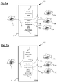
- FIG. 1A illustrates a communication system 100 for a conference session of four users.
- a communication terminal 1, e.g. a smart phone, a tablet PC, an IP Phone or a PC client, of the first user is connected to a mixing unit 3 in form of a Media Streamer, i.e. in form of a Web-server, or a conference unit via connection link 6.
- the transmission and mixing of data from users of the conference session is established by the communication system 100.
- Other protocols for transmission of the data between the users of the conference session are possible.
- Additional communication terminals 5A, 5B, 5C, e.g. wired telephones or cellular phones, of a second or more users are linked to the mixing unit 3 by communication links 7A, 7B, and 7C, respectively.
- the mixing unit 3 and a media processing unit 2 are comprised by a private automated branch exchange 4.
- audio/video data of the uses are transmitted between the communication terminals 1, 5A, 5B, and 5C downstream, i.e. from the mixing unit 3 to the communication terminals 1, 5A, 5B, 5C, also called from a server to a client, and upstream, i.e. from at least one of the communication terminals 1, 5A, 5B, 5C to the mixing unit 3, also called from the client to the server, the exchange of data from the communication terminals, also called clients, occurs via the mixing unit 3 without involvement of the media processing unit 2.
- the mixing unit 3 would pass through the data of the first user and the second user without mixing.
- the mixing unit may be missing for a communication link between the first (1) and the second (5A) communication terminals using only the switching function of the PBX or PABX if required.
- the conference session comprises a passive mode, e.g. of the first user, wherein the data is received and transmitted by the first communication terminal 1 as passive data but not received by the second terminal, 5A, 5B, 5C, i.e. allowing transmission of data upstream and downstream between the mixing unit 3 and the first communication terminal 1 but not downstream from the mixing unit 3 to the second communication terminal, 5A, 5B, 5C, and an active mode of the first user, wherein the data is received by the first communication terminal 1 from the second communication terminal, 5A, 5B, 5C and transmitted by the first communication terminal 1 to the second communication terminal, 5A, 5B, 5C, i.e.
- the first communication terminal 1 is not directly connected to the mixing unit 3 but linked via communication link 8 to the media processing unit 2 which is linked via communication link 9 to the mixing unit 3.
- the first duration of passive data left to be transmitted is recorded and replayed in a faster speed as the speed during recording and simultaneously to the recording by the media processing unit 2 after switching to the active mode in order to catch up with a real-time conversation in the active mode between the users of the conference session.
- FIG. 2 illustrates the case of FIG. 1B for the embodiment that the first user is muted, also called mute-on mode or mute activated mode, which is defined as the passive mode, and there is a switchover from the mixing unit 3, which may be a conference unit (DSP unit), a conference server or a media processing unit, to the media processing unit 2.
- the mixing unit 3 may be a conference unit (DSP unit), a conference server or a media processing unit
- RTP packets received from the first communication terminal 1 are no longer directed in the communication system 100 to the mixing unit 3 but to the media processing unit 2, wherein the media processing unit 2 sends (processed) RTP packets to the mixing unit 3.
- the upper region 1A in FIG. 2 represents (a timing of data transmitted by) the first communication terminal 1.
- the media processing unit 2 represents the media processing unit 2 in a recording mode 2R and a replaying mode 2P.
- the media processing unit 2 starts recording, 11, when the first user activates mute-on, 12, which may retain a time window for saving memory used for recording in the media processing unit 2.
- the lengths of the horizontal arrows 12 to 26 displayed in FIG. 2 - and other horizontal arrows in FIG. 3 , 5 , 6 , and 7 - represent relative durations/periods in time to each other (see direction of arrow of time "t" in the upper left corner of FIG. 2 - and "t” in FIG. 3 , 5 , 6 , and 7 ).
- the first user decides to talk at the beginning of arrow 13 representing a voice activity detection response duration.
- the voice of the first user is detected at the end of the voice activity detection response duration 13, which may be in the order of 1 to 3 msec.
- the muting is automatically deactivated after a certain period of time, this means that during the muting duration a content spoken by the first user would be lost if not recorded by the media processing unit 2.
- the first user continues to talk after the point-in-time when the mute is deactivated and payload has been established upstream and downstream between the first user and the second user.
- the voice activity detection response duration 13 in this embodiment is the first duration of the passive data, which is recorded along with a second duration 14 of the active data of the first user starting from the switching point-in-time 13A of the switching from passive mode to active mode. Therefore, at the start of the second duration 14 mute is deactivated automatically by switching to the active mode, and whatever was said during the voice activity detection response duration 13 is transmitted from the media processing unit 2 to the mixing unit 3.
- the recording may be arranged for all the users of the conference session by an individual Round recording buffer per user e.g. at the media processing unit 2 or the mixing unit 3, the Round Robin process referring to a pattern or ordering whereby recent recordings overwrite previous recording sequences per user in a circular manner.
- a faster speed is chosen for a hastened replaying of the recorded first duration 13 of the passive data and the recorded second duration 14 of the active data via the media processing unit 2 and transmitted to the communication terminals 5A, 5B, 5C via the mixing unit 3 and communication links 7A, 7B, 7C (see smaller lengths of the replayed voice activity detection response duration 23 and replayed second duration 24 to the recorded voice activity detection response duration 13 and recorded second duration 14.
- the recording continues as illustrated in FIG. 2 by the second durations 15, 16.
- the hastened replaying continues as long as a synchronization delay 27 between a first end 18 of the second duration 16 of the active data of the first user during recording and a second end 26A of the replayed second duration 26 of the active data after recording is equal or smaller than a predetermined duration.
- the media processing unit 2 therefore continues to replay to the mixing unit 3 the recorded second durations 15, 16 as replayed second durations 25, 26 until the replayed audio/video data of the first user is within a predetermined duration for a synchronization delay 27.
- the synchronization delay is within the predetermined duration, which may be 10 to 100 msec, preferably 30 to 50 msec, there is a switching-off of the recording at a switchover point 17 where the media processing unit 2 no longer records and no longer replays such that the mixing unit 3 is now supplied with audio/video data by the communication terminal 1 (see second duration 19 in active mode) without involvement from or detouring of the media processing unit 2.
- the communication system 100 starts to transmit the data of the first user in real-time to the second user.
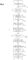
- the flowchart of the schematic timeline of FIG. 2A starts with the first user activating mute, S21, wherein the recording, S22, begins, leading to a switchover to the media processing unit 2, S23, which initiates the mute-off detection, S24, in the form of a voice activity detection.
- the mute-off detection continues until the first user starts talking leading to a switchover from passive mode to active mode and hastened replaying, S25, of the recorded/video data of the first user compared to the speed of recording.
- the recording continues, S26, as long as the last recorded session time difference, also called synchronization delay, is less then predetermined duration measured in milliseconds, S27 (see x ms in step S27 in Fig.
- x is an integer, e.g. 1 to 100, preferably 30-50, and ms are milliseconds).
- FIG. 3 illustrates another embodiment of the invention in a schematic timeline comprising a real-time active mode and a delayed passive mode.
- the first communication terminal 1 (and a timeline of the data transmission thereof) is represented by horizontal bar 1B, whereas the media processing unit 2 is represented by horizontal bar 2B.
- a conference session with active and passive participants/users is established by the communication system 100.
- the users are served differently in terms of active users communicating with real-time media exchanged via e.g. a conference server, 3A, and passive users receiving media/data by streaming, 36, e.g. over https delivered e.g. by a Media Streamer, typically a Web-server, 3B, wherein the conference server and the Media Streamer may by comprised by the mixing unit 3.
- This embodiment may occur especially in a conference of a large number of participants, e.g. tens or hundreds of users as passive users and a few users as active users.
- the media streaming may be subject to significant additional delay (approximately 3 - 5 sec) compared to real-time communication of the active mode.
- streaming may not be suitable for online, i.e. real-time, communication but may be sufficient to save processing power at the conference and/or mixing unit for a large number of passive users, because the media sent by passive users are not required to be processed as long as the streaming delay is not perceived by users staying in passive mode.
- a passive user may change to an active user to contribute to the discussion of the active users.
- the notion of "Raise Hand" 31 is known for passive users, 30, that may be muted to avoid background noise in large or mobile configurations.
- a moderator by user interaction or the communication system 100 automatically may switch the first user from passive to active mode, 32. Due to a non-negligible encoding delay, the real-time communication may be a few second ahead of the streaming communication leading to a time gap to be catched up with smoothly, preferable not perceived by the transitioned first user 33 and/or the other conferees such as the second user.
- the media processing unit 2 starts recording, 37A, of the real-time media 37 captured from the first communication device 1.
- a replay buffer (not shown) of the media streaming may still contain media frames, 36B, to be delivered to the first user's first communication device 1 to avoid information loss.
- the media processing unit 2 may provide at least one preconditioned/optimized media/data stream 36A in parallel to the regular media streaming 36 for the purpose of saving time during replay, e.g. in form of processed data comprising a reduced transfer delay and/or omitted complementary encoding layers compared to the regular media streaming 36.
- the hastened replay (see replayed duration 37B) of the recorded duration 37A of the real-time data 37 after switching to active mode starts (seamlessly) continuing with the replayed duration 38B of the meanwhile recorded media (see duration 38A) of the real-time duration 38 until the replayed media/data is timely within a predetermined synchronization delay with the real-time media.
- This is the point-in-time where the first user is switched from the media processing unit 2 to a conference server comprised by the mixing unit 3.
- 2R also called Sync Point 34
- 2R starts the transmission of real-time data from the first communication device 1 to the mixing unit 3, i.e. upstream, 39, and from mixing unit 3 to the first communication device 1, i.e. downstream, 39A.
- the transitional mode 33 and the active user mode 35 of the first user following the Sync Point 34 are defined to be comprised by the active mode starting from the switching point-in-time. Concluding, the timeline starting with duration 37B corresponds to the un-mute use illustrated in FIG. 2 starting from the second duration 24.
- FIG. 4 illustrates a flowchart of the schematic timeline of FIG. 3 and starts with the first user being a passive user raising hand, 31.
- a moderator/administrator of the conference session switches the first user from passive mode to active mode, S41, which stops the regular streaming from the Media Streamer to the first communication terminal 1 (down streaming, S42). It begins a recording, S43, of audio/video data being streamed (in passive mode) from the second communication terminal 5A, 5B, 5C to the media processing unit 2, i.e. upstream, wherein the media processing unit 2 may provide optionally a modified/pre-conditioned media stream in order to promote hastened replaying, S44, in addition to or instead of the recorded stream of S43.
- Remaining queued streaming frames are transmitted, S 45, from the media processing unit 2 to the first communication terminal 1.
- S46 to the first communication terminal 1, replaying of the preconditioned remaining queued streaming frames or of the remaining queued streaming frames without preconditioning and subsequently hastened replaying of the recorded media/data which have been transmitted to the media processing unit 2 (upstream) starts, S47.
- S48 Once the last recorded content of the recorded data has been replayed, S48, the recording of the first user is switched-off and the first user is switched from streaming to real-time in the active mode, 32.
- the first user is then in active mode (activated) which enables bi-directional real-time communication between the first user and the second user, S 49, which ends the flow illustrated in FIG. 4 .
- FIG. 5 illustrates a schematic timeline of the inventive method comprising an intended delay 51 added by the communication system 100 to synchronize data streams of the users of the conference session.
- the first communication terminal 1 is represented, while the media processing unit 2 is represented in the lower region 2C.
- intentional delays may be introduced in order to synchronize streams.
- This intended delay can be exploited by prioritizing streams of users that use the inventive method.
- the silence duration is deterred to a smaller amount.
- the voice activity detection response duration 13 is utilized to provide the intended delay 51.
- the voice activity detection response duration is the duration of silence with the first user still being muted, the silence duration may occur during this intended delay.
- FIG. 6 illustrates a schematic timeline of the inventive method comprising an interruption after the switching from passive mode to active mode.
- the embodiment addresses the case where the second user as another user intervenes while the media processing unit 2 replays the recorded voice/video content of the first user.
- the first communication terminal 1 is represented, while the media processing unit 2 is represented in the lower region 2D.
- the other user is interrupting the conversation which leads to an interruption of the replaying at an interruption point-in-time 61.
- the other user may be polite that the first user stops talking and waits for the other user to finish. This means that the switchover point 17 of switching-off the recording 18 is shifted to the interruption point-in-time 61.
- FIG. 7 illustrates a schematic timeline of the inventive method comprising an interruption point-in-time 71 before the switching point-in-time 17 from passive mode to active mode leading to the switching-off point-in-time 18 for the recording.
- the interruption point-in-time 71 may be introduced when the first user talks and unmute has not been detected yet.
- the switchover point 17 is shifted to the end of the voice activity detection response duration 13 at the point-in-time 18 when the recording is switched-off. This means that information being sent after the detection of voice is lost, shown in FIG. 7 as the duration 72 in black.
- the second user will only hear what has been said while on mute.
- the recorded data while on mute has been recorded and is replayed while the first user continues to speak.
- this duration shown as a gap 73 and FIG. 7 the first user will in addition to his real-time voice hear his voice as recorded on mute before the recording has been switched-off. Therefore, the first user will know that whatever he said before the interruption is not lost but transmitted to the second user. Then it is up to the users to decide who would continue to talk as it may happen in conferences when two users are trying to talk at the same time.
- an interrupt triggered by the second user will be indicated from the relevant media processing unit serving the second user.
- a technical feature or several technical features which has/have been disclosed with respect to a single or several embodiments discussed herein before, e.g. utilizing several media processing units, may be present also in another embodiment, e.g. the embodiment comprising a real-time active mode and a delayed passive mode displayed in FIG. 3 and FIG. 4 , respectively, except it is/they are specified not to be present or it is impossible for it/them to be present for technical reasons.
Landscapes
- Engineering & Computer Science (AREA)
- Multimedia (AREA)
- Signal Processing (AREA)
- Computer Networks & Wireless Communication (AREA)
- Business, Economics & Management (AREA)
- General Business, Economics & Management (AREA)
- General Engineering & Computer Science (AREA)
- Computer Vision & Pattern Recognition (AREA)
- Telephonic Communication Services (AREA)
- Two-Way Televisions, Distribution Of Moving Picture Or The Like (AREA)
Description
- The invention relates to a method of controlling a real-time conference session. The invention further relates to a computer program product causing a computer to execute the method, and a communication system for controlling the real-time conference session.
- There is a multitude of video conference systems published. For instance
US 2008/0137558 discloses a method including a receiving input indicating that an endpoint is dropping out of a real-time mode of attending an ongoing conference session. - A modern conference session, also abbreviated as conference, can be established by a mixing unit in the form of a conference bridge or Media Streamer. The Media Streamer executes an application for controlling of a conference which can be defined as a program, in particular a computer program or application software that allows an administrator to control the conference. When the application for controlling a conference is running on a computer, the application is able to provide a mixture of speech signals from participants, also called users, of the conference. The application for controlling the conference can be installed on a personal computer, abbreviated to PC, and/or run on the PC. Such a PC is also referred to as the Media Streamer, a media server or application server. In the following, besides to a computer on which the application is installed to control the conference, so for example, the Media Streamer, media server or application server, the application for controlling the conference itself is called Media Server. To that extent, in the following, the term "Media Streamer", which is also called "conference server", is equally used for execution of the application software for controlling the conference in the form of software, and in a form of this application in hardware. The Media Streamer is set up to receive as a server from each of the communication terminals of the conference participants the respective audio/video signals and to transmit the mixed audio/video signals to communication terminals of the conference participants. There is a difference such that for active participants all except the own image/voice is mixed individually by the conference unit, whereas for passive participants in streaming mode all passive users receive the same images/voice. Therefore the streaming mode is advantageous in large conferences because the processing power of the conference unit is significantly reduced compared to a case where for each participant all except the own image/voice is mixed individually by the conference unit. As a communication terminal of a participant may act a telephone unit, an IP Phone (IP: internet Protocol) or a PC client, wherein another communication terminal, such as a mobile telephone or another server, is possible.
- Under a conference session it is in particular understood a conference in which at least two participants of the conference are not resident at a same place/location such that they cannot communicate with each other without the use of technical means. The communication of the participants will rather be executed via the mixing unit by mixing the voice signals of the participants, wherein said conference can be configured for example as a teleconference or videoconference. In a teleconference, participants communicate only by exchange of speech regardless of how the voice signals of the participants are transferred. Therefore, both a teleconference over a landline and a teleconference in which one or more participants communicate with each other over a cellular network are called teleconference.
- In addition, a conference in the form of a video conference is possible with image signals of the participants being transmitted in real-time to other participants in addition to the exchange of voice signals of the participants. In the following, however, a conference is also meant to comprise an application sharing wherein other media are to be exchanged between the participants of the conference in addition to the exchange of voice and video data of the participants, for example in the form of a transfer of data between the participants. This data can be shifted/delayed in time with respect to the real-time data of the voice and/or image signals of the participants and can be displayed on a screen, for example the screen of a personal computer. In general, the mixing unit in form of a media Streamer can be connected via a network, for example, the intranet or the Internet, to the communication terminals of the participants of the conference. In this case, the voice and/or video and/or data signals are transferred in the form of data packets from one participant to another participant in the conference.
- In a telephone conversation for example in a conference session, participants often activate mute for preventing persons from hearing background noise from their desk or in order to discuss another issue while participating in the conference session. This mute mode can be deactivated when the user presses an unmute or mute-off button. However there are times when a user forgets to press the mute-off button and by the time the participant starts to talk mute is still on and apparently the other participants of the conference are not able to listen to the talking participant until the talking participant realizes to unmute or mute-off and repeat the content already spoken. While there are mechanisms that detect voice activity and automatically switch-off the mute button, these highly sophisticated mechanisms require some time until the unmute has been activated for the voice of the formerly muted participant to be transmitted to the other participants. Under optimal circumstances the response behavior of this voice activity recognition and subsequent automatic unmute may require in the order of 2 to 3 seconds in which some useful information of the muted talking participant may be lost. It is therefore desired to better reduce a loss of information when a user of a conference session forgets to unmute.
- A similar problem arises for a conference session where a single or few participants are actively participating and a large group of other participants is passive, i.e. listening only to the subject matter of the single or few actively participating participants. Such a case may arise in panel discussions or webinars. Active participants served via a fast communication channel may be served via a fast voice and/or video conferencing channel. Passive participants may be served via a different slower voice and/or video conferencing channel leading to a delay in receiving the data for the passive participant when compared to a same point-in-time of reception of the data by an active participant. The delay is not critical for the passive participant as long as the participant stays passive. However, a passive participant may want do an utterance or temporarily take part in the discussion of the active participants, typically introduced by a so called "raise hand" or similar indication. After this indication, the administrator or moderator may turn a passive participant into an active participant with a notification. Thus, the participant that indicated to take part in the discussion of the active participants gets connected via real-time to a point-in-time of the discussion he is not aware of because of the streaming delay prohibiting this participant to catch up to point-in-time of the real-time discussion. This situation is comparable to the situation as described for a muted participant forgetting to unmute before starting to talk. It is thus desired to better reduce a loss of information when a passive user receiving delayed data with respect to an active user of a conference session is turned into an active user. It is therefore the object of the invention to provide a method which better reduces a loss of information when a passive user of a conference session is turned into an active user.
- The object is solved by the method of controlling a real-time conference session according to
independent claim 1, by the computer program product causing a computer to execute the method according toindependent claim 9, by the machine readable medium according toindependent claim 10 and by the communication system for controlling a real-time conference session according toindependent claim 11 - Further embodiments are defined in the dependent claims.
- Further embodiments and advantages of the invention are highlighted in the following with respect to figures. For an improved clearness, the figures are not true to scale or proportionate. In the figures, as long as not mentioned otherwise, same references indicate same parts with same meaning. It illustrates:
-
FIG. 1A, 1B schematic diagrams of a communication system for a conference session of four users comprising a media processing unit according to the invention in a first embodiment, -
FIG. 2 a schematic timeline of the method according to the invention comprising a muted user in a second embodiment, -
FIG. 2A a flowchart of the schematic timeline ofFIG. 2 according to the invention, -
FIG. 3 a schematic timeline of the method according to the invention comprising a real-time active mode and a delayed passive mode in a third embodiment, -
FIG. 4 a flowchart of the schematic timeline ofFIG. 3 according to the invention, -
FIG. 5 a schematic timeline of the method according to the invention comprising an intended delay added by the communication system in a fourth embodiment, -
FIG. 6 a schematic timeline of the method according to the invention comprising an interruption after the switching from passive mode to active mode in a fifth embodiment, and -
FIG. 7 a schematic timeline of the method according to the invention comprising an interruption before the switching from passive mode to active mode in a sixth embodiment. -
FIG. 1A illustrates acommunication system 100 for a conference session of four users. Acommunication terminal 1, e.g. a smart phone, a tablet PC, an IP Phone or a PC client, of the first user is connected to amixing unit 3 in form of a Media Streamer, i.e. in form of a Web-server, or a conference unit viaconnection link 6. The transmission and mixing of data from users of the conference session is established by thecommunication system 100. Other protocols for transmission of the data between the users of the conference session are possible.Additional communication terminals mixing unit 3 bycommunication links mixing unit 3 and amedia processing unit 2 are comprised by a privateautomated branch exchange 4. When audio/video data of the uses are transmitted between thecommunication terminals unit 3 to thecommunication terminals communication terminals mixing unit 3, also called from the client to the server, the exchange of data from the communication terminals, also called clients, occurs via themixing unit 3 without involvement of themedia processing unit 2. In an embodiment of only two users to be connected the mixingunit 3 would pass through the data of the first user and the second user without mixing. Alternatively, the mixing unit may be missing for a communication link between the first (1) and the second (5A) communication terminals using only the switching function of the PBX or PABX if required. - When the conference session comprises a passive mode, e.g. of the first user, wherein the data is received and transmitted by the
first communication terminal 1 as passive data but not received by the second terminal, 5A, 5B, 5C, i.e. allowing transmission of data upstream and downstream between the mixingunit 3 and thefirst communication terminal 1 but not downstream from the mixingunit 3 to the second communication terminal, 5A, 5B, 5C, and an active mode of the first user, wherein the data is received by thefirst communication terminal 1 from the second communication terminal, 5A, 5B, 5C and transmitted by thefirst communication terminal 1 to the second communication terminal, 5A, 5B, 5C, i.e. allowing transmission of data downstream and upstream between the mixingunit 3 and thefirst communication terminal 1 and downstream and upstream between the mixingunit 3 and the second communication terminal, 5A, 5B, 5C, it is possible that after switching from the passive mode to the active mode the first duration of the passive data of the first user is not transmitted to the second user and therefore left to be transmitted to the second user. As shown inFIG. 1B , in such a case, thefirst communication terminal 1 is not directly connected to themixing unit 3 but linked viacommunication link 8 to themedia processing unit 2 which is linked viacommunication link 9 to themixing unit 3. Instead of directly transmitting voice/video data after the switching from passive mode to active mode via themixing unit 3 to thecommunication terminals media processing unit 2 after switching to the active mode in order to catch up with a real-time conversation in the active mode between the users of the conference session. -
FIG. 2 illustrates the case ofFIG. 1B for the embodiment that the first user is muted, also called mute-on mode or mute activated mode, which is defined as the passive mode, and there is a switchover from the mixingunit 3, which may be a conference unit (DSP unit), a conference server or a media processing unit, to themedia processing unit 2. Following the switchover from the mixingunit 3 to themedia processing unit 2 RTP packets received from thefirst communication terminal 1 are no longer directed in thecommunication system 100 to themixing unit 3 but to themedia processing unit 2, wherein themedia processing unit 2 sends (processed) RTP packets to themixing unit 3. Theupper region 1A inFIG. 2 represents (a timing of data transmitted by) thefirst communication terminal 1. Thelower region 2A inFIG. 2 represents themedia processing unit 2 in arecording mode 2R and a replayingmode 2P. Before a switching point-in-time 13A of switching from the passive mode to the active mode, themedia processing unit 2 starts recording, 11, when the first user activates mute-on, 12, which may retain a time window for saving memory used for recording in themedia processing unit 2. The lengths of thehorizontal arrows 12 to 26 displayed inFIG. 2 - and other horizontal arrows inFIG. 3 ,5 ,6 , and7 - represent relative durations/periods in time to each other (see direction of arrow of time "t" in the upper left corner ofFIG. 2 - and "t" inFIG. 3 ,5 ,6 , and7 ). - At some point-in-time after muting the first user decides to talk at the beginning of
arrow 13 representing a voice activity detection response duration. The voice of the first user is detected at the end of the voice activitydetection response duration 13, which may be in the order of 1 to 3 msec. When the muting is automatically deactivated after a certain period of time, this means that during the muting duration a content spoken by the first user would be lost if not recorded by themedia processing unit 2. The first user continues to talk after the point-in-time when the mute is deactivated and payload has been established upstream and downstream between the first user and the second user. - The voice activity
detection response duration 13 in this embodiment is the first duration of the passive data, which is recorded along with asecond duration 14 of the active data of the first user starting from the switching point-in-time 13A of the switching from passive mode to active mode. Therefore, at the start of thesecond duration 14 mute is deactivated automatically by switching to the active mode, and whatever was said during the voice activitydetection response duration 13 is transmitted from themedia processing unit 2 to themixing unit 3. As the end point-in-time for the voice activitydetection response duration 13 is not known up front, the recording may be arranged for all the users of the conference session by an individual Round recording buffer per user e.g. at themedia processing unit 2 or themixing unit 3, the Round Robin process referring to a pattern or ordering whereby recent recordings overwrite previous recording sequences per user in a circular manner. - Compared to the recording speed a faster speed is chosen for a hastened replaying of the recorded
first duration 13 of the passive data and the recordedsecond duration 14 of the active data via themedia processing unit 2 and transmitted to thecommunication terminals mixing unit 3 andcommunication links detection response duration 23 and replayedsecond duration 24 to the recorded voice activitydetection response duration 13 and recordedsecond duration 14. The recording continues as illustrated inFIG. 2 by thesecond durations synchronization delay 27 between afirst end 18 of thesecond duration 16 of the active data of the first user during recording and asecond end 26A of the replayedsecond duration 26 of the active data after recording is equal or smaller than a predetermined duration. Themedia processing unit 2 therefore continues to replay to themixing unit 3 the recordedsecond durations second durations synchronization delay 27. When the synchronization delay is within the predetermined duration, which may be 10 to 100 msec, preferably 30 to 50 msec, there is a switching-off of the recording at aswitchover point 17 where themedia processing unit 2 no longer records and no longer replays such that themixing unit 3 is now supplied with audio/video data by the communication terminal 1 (seesecond duration 19 in active mode) without involvement from or detouring of themedia processing unit 2. This way, thecommunication system 100 starts to transmit the data of the first user in real-time to the second user. - The flowchart of the schematic timeline of
FIG. 2A starts with the first user activating mute, S21, wherein the recording, S22, begins, leading to a switchover to themedia processing unit 2, S23, which initiates the mute-off detection, S24, in the form of a voice activity detection. The mute-off detection continues until the first user starts talking leading to a switchover from passive mode to active mode and hastened replaying, S25, of the recorded/video data of the first user compared to the speed of recording. The recording continues, S26, as long as the last recorded session time difference, also called synchronization delay, is less then predetermined duration measured in milliseconds, S27 (see x ms in step S27 inFig. 2A , wherein x is an integer, e.g. 1 to 100, preferably 30-50, and ms are milliseconds). Once the predetermined duration is reached or undercut, the last recorded second duration of the active data is replayed in faster mode, S28. Then, thecommunication system 100 switches over to thefirst communication terminal 1, S29, where the flow ofFIG. 2A ends. -
FIG. 3 illustrates another embodiment of the invention in a schematic timeline comprising a real-time active mode and a delayed passive mode. The first communication terminal 1 (and a timeline of the data transmission thereof) is represented by horizontal bar 1B, whereas themedia processing unit 2 is represented by horizontal bar 2B. A conference session with active and passive participants/users is established by thecommunication system 100. The users are served differently in terms of active users communicating with real-time media exchanged via e.g. a conference server, 3A, and passive users receiving media/data by streaming, 36, e.g. over https delivered e.g. by a Media Streamer, typically a Web-server, 3B, wherein the conference server and the Media Streamer may by comprised by the mixingunit 3. This embodiment may occur especially in a conference of a large number of participants, e.g. tens or hundreds of users as passive users and a few users as active users. The media streaming may be subject to significant additional delay (approximately 3 - 5 sec) compared to real-time communication of the active mode. Thus, streaming may not be suitable for online, i.e. real-time, communication but may be sufficient to save processing power at the conference and/or mixing unit for a large number of passive users, because the media sent by passive users are not required to be processed as long as the streaming delay is not perceived by users staying in passive mode. - However, a passive user may change to an active user to contribute to the discussion of the active users. To this end, e.g. from Webinars the notion of "Raise Hand", 31, is known for passive users, 30, that may be muted to avoid background noise in large or mobile configurations. Based on this user indication of the first user a moderator by user interaction or the
communication system 100 automatically may switch the first user from passive to active mode, 32. Due to a non-negligible encoding delay, the real-time communication may be a few second ahead of the streaming communication leading to a time gap to be catched up with smoothly, preferable not perceived by the transitionedfirst user 33 and/or the other conferees such as the second user. This is a similar scenario compared to the automated un-mute applying voice (activity) detection with the difference that the point-in-time of switching from passive mode to active mode is known/triggered by thecommunication system 100 and not by the first user. Hence, the embodiment illustrated inFIG. 3 is different in this respect. - At the point-in-time of switching the first user from passive mode to active mode, 32, the
media processing unit 2 starts recording, 37A, of the real-time media 37 captured from thefirst communication device 1. At the switching point-in-time 32 a replay buffer (not shown) of the media streaming may still contain media frames, 36B, to be delivered to the first user'sfirst communication device 1 to avoid information loss. In another embodiment, themedia processing unit 2 may provide at least one preconditioned/optimized media/data stream 36A in parallel to theregular media streaming 36 for the purpose of saving time during replay, e.g. in form of processed data comprising a reduced transfer delay and/or omitted complementary encoding layers compared to theregular media streaming 36. As soon as the remainingframes 36B are delivered by theregular media stream 36 and/or the preconditionedmedia streaming 36A of themedia processing unit 2 by replaying, the hastened replay (see replayedduration 37B) of the recordedduration 37A of the real-time data 37 after switching to active mode starts (seamlessly) continuing with the replayed duration 38B of the meanwhile recorded media (seeduration 38A) of the real-time duration 38 until the replayed media/data is timely within a predetermined synchronization delay with the real-time media. This is the point-in-time where the first user is switched from themedia processing unit 2 to a conference server comprised by the mixingunit 3. At the switching-off point-in-time 17 of the recording, 2R, also calledSync Point 34, starts the transmission of real-time data from thefirst communication device 1 to themixing unit 3, i.e. upstream, 39, and from mixingunit 3 to thefirst communication device 1, i.e. downstream, 39A. Thetransitional mode 33 and theactive user mode 35 of the first user following theSync Point 34 are defined to be comprised by the active mode starting from the switching point-in-time. Concluding, the timeline starting withduration 37B corresponds to the un-mute use illustrated inFIG. 2 starting from thesecond duration 24. -
FIG. 4 illustrates a flowchart of the schematic timeline ofFIG. 3 and starts with the first user being a passive user raising hand, 31. A moderator/administrator of the conference session switches the first user from passive mode to active mode, S41, which stops the regular streaming from the Media Streamer to the first communication terminal 1 (down streaming, S42). It begins a recording, S43, of audio/video data being streamed (in passive mode) from thesecond communication terminal media processing unit 2, i.e. upstream, wherein themedia processing unit 2 may provide optionally a modified/pre-conditioned media stream in order to promote hastened replaying, S44, in addition to or instead of the recorded stream of S43. Remaining queued streaming frames are transmitted, S 45, from themedia processing unit 2 to thefirst communication terminal 1. Once the last frame has been transmitted, S46, to thefirst communication terminal 1, replaying of the preconditioned remaining queued streaming frames or of the remaining queued streaming frames without preconditioning and subsequently hastened replaying of the recorded media/data which have been transmitted to the media processing unit 2 (upstream) starts, S47. Once the last recorded content of the recorded data has been replayed, S48, the recording of the first user is switched-off and the first user is switched from streaming to real-time in the active mode, 32. The first user is then in active mode (activated) which enables bi-directional real-time communication between the first user and the second user,S 49, which ends the flow illustrated inFIG. 4 . -
FIG. 5 illustrates a schematic timeline of the inventive method comprising an intendeddelay 51 added by thecommunication system 100 to synchronize data streams of the users of the conference session. For avoiding repetitive description, only the differences toFIG. 2 are highlighted. In the upper region 1C ofFIG. 5 , thefirst communication terminal 1 is represented, while themedia processing unit 2 is represented in thelower region 2C. Especially in real-time communications over IP intentional delays may be introduced in order to synchronize streams. The intentional delay effect that other users may hear the voice of the first user sometime later then the first user himself. This intended delay can be exploited by prioritizing streams of users that use the inventive method. By providing part of the voice activitydetection response duration 13 as the intended delay the silence duration is deterred to a smaller amount. Instead of generating an intended delay for synchronizing data streams of users of the conference session, at least part of the voice activitydetection response duration 13 is utilized to provide the intendeddelay 51. As the voice activity detection response duration is the duration of silence with the first user still being muted, the silence duration may occur during this intended delay. -
FIG. 6 illustrates a schematic timeline of the inventive method comprising an interruption after the switching from passive mode to active mode. The embodiment addresses the case where the second user as another user intervenes while themedia processing unit 2 replays the recorded voice/video content of the first user. In theupper region 1 D ofFIG. 6 , thefirst communication terminal 1 is represented, while themedia processing unit 2 is represented in thelower region 2D. The other user is interrupting the conversation which leads to an interruption of the replaying at an interruption point-in-time 61. When the other user is interrupting the first user, it may be polite that the first user stops talking and waits for the other user to finish. This means that theswitchover point 17 of switching-off therecording 18 is shifted to the interruption point-in-time 61. Once this occurs, all information/data that ought to be recorded is automatically shifted to thecommunication terminal 1, represented byregion 1D. The recording is stopped andsubsequent durations first communication terminal 1 upstream asdurations durations durations time 63A during replaying. All other information from point-in-time 63A to point-in-time 62A causing the stop of the recording is discarded although the first user has already talked during the duration from point-in-time 63A to 62A. The durations in replaying from point-in-time 63A to point-in-time 62A are displayed inFIG. 6 asdurations duration 62. Theduration 63 before the lostduration 64B corresponds to theduration 13 recorded before the interruption point-in-time 61. After the point-in-time 62A, it is not spoken which is displayed inFIG. 6 by greyeddurations first communication terminal 1, these packets/data -
FIG. 7 illustrates a schematic timeline of the inventive method comprising an interruption point-in-time 71 before the switching point-in-time 17 from passive mode to active mode leading to the switching-off point-in-time 18 for the recording. Inupper region 1E ofFIG. 7 , thefirst communication terminal 1 is represented, while themedia processing unit 2 is represented in thelower region 2E. The interruption point-in-time 71 may be introduced when the first user talks and unmute has not been detected yet. In this case theswitchover point 17 is shifted to the end of the voice activitydetection response duration 13 at the point-in-time 18 when the recording is switched-off. This means that information being sent after the detection of voice is lost, shown inFIG. 7 as theduration 72 in black. Therefore, other users such as the second user will only hear what has been said while on mute. The recorded data while on mute has been recorded and is replayed while the first user continues to speak. In this duration shown as agap 73 andFIG. 7 , the first user will in addition to his real-time voice hear his voice as recorded on mute before the recording has been switched-off. Therefore, the first user will know that whatever he said before the interruption is not lost but transmitted to the second user. Then it is up to the users to decide who would continue to talk as it may happen in conferences when two users are trying to talk at the same time. - Instead of a single
media processing unit 2, several media processing units may be utilized to carry out the present invention. In this embodiment, an interrupt triggered by the second user will be indicated from the relevant media processing unit serving the second user. - A technical feature or several technical features which has/have been disclosed with respect to a single or several embodiments discussed herein before, e.g. utilizing several media processing units, may be present also in another embodiment, e.g. the embodiment comprising a real-time active mode and a delayed passive mode displayed in
FIG. 3 andFIG. 4 , respectively, except it is/they are specified not to be present or it is impossible for it/them to be present for technical reasons.
Claims (12)
- Method of controlling a real-time conference session, the method comprising:- connecting a first communication terminal (1) of a first user and a second communication terminal (5A, 5B, 5C) of a second user to a media processing unit (2) for transmitting of audio and/or video data between the first user and the second user, wherein the conference session comprises:when a synchronization delay (27), between a first end (18) of the second duration (16) of the active data of the first user during recording (S22, S43) and a second end (26A) of the replayed second duration (26) of the active data of the first user after recording, is equal or smaller than a predetermined duration, switching-off (17, S29, 34) of the recording (S22, S43) and the hastened replaying and starting to transmit (S49) active data of the first user in real-time to the second user.- a passive mode (30) of the first user, wherein the data is received and transmitted by the first communication terminal (1) as passive data but not received by the second terminal (5A, 5B, 5C), and- an active mode (33, 35) of the first user, wherein the data is received and transmitted by the first communication terminal (1) and received by the second terminal (5A, 5B, 5C) as active data of the first user,the method being characterized in that:- during a first duration of the first user being in the passive mode, recording (S22, S43) of the passive data of the first user, wherein the first duration starts prior to a switching point-in-time and ends at the switching-point-in-time,- at the switching point-in-time (13A, 32), switching (S41) from the passive mode (30) of the first user to the active mode (33, 35) of the first user, wherein at the switching point-in-time the passive data of the first user recorded during the first duration is left to be transmitted to the second user,- after the switching and starting at the switching point-in-time, recording of the active data of the first user during a second duration,- after the switching (S41) and simultaneously with starting the recording (S22, S43) of the active data of the first user at the switching point-in-time, starting hastened replaying to the second user, at a speed faster than the recording speed, of the recorded first duration of the passive data of the first user followed by the recorded second duration of the active data of the first user, and,
- The method of claim 1, wherein
a loss of information of the recorded first duration (12, 13, 36B) of the passive data and/or the recorded second duration (14, 15, 16, 37, 38) of the active data is introduced during the recording (S22, S43) and/or the replaying (S28, S48) for achieving the hastened replaying (S28, S48). - The method of claim 1 or claim 2, wherein
the predetermined duration of the synchronization delay (27) is defined as n times 10 msec, wherein n is an integer between 1 and 10. - The method of one of the preceding claims, wherein,
when the first user is interrupted by the second user at a first interruption point-in-time (61) after the recording (S22, S43) of the second duration (14, 15, 16, 37, 38) of the active data of the first user has started, the hastened replaying (S28, S48) of the recorded first duration (12, 13, 36B) of the passive data and the recorded second duration (14, 15, 16, 37, 38) of the active data to the second user ends at the first interruption point-in-time (61) and the switching-off (S29, 32) of the recording (S22, S43) and starting to transmit (S49) the data of the first user in real-time to the second user is shifted to the first interruption point-in-time (61). - The method of one of the preceding claims, wherein,
when in the passive mode (30) the first user is muted and does not activate an unmute function for getting switched to the active mode (33, 35) after starting to speak, wherein the first duration (12, 13) ending at the switching point-in-time (13A, 32) comprises a voice activity detection response duration (13), and when the voice activity detection response duration (13) ends, the switching (S41) from the passive mode (30) to the active mode (33, 35) is triggered by a voice activity detection unit by automatically activating the unmute function. - The method of claim 5, wherein,
when in real-time communications over IP there is an intentional delay (51) to be introduced for synchronizing streams of the first user and the second user of the conference session, at least part of the voice activity detection response duration (13) is utilized as the intentional delay (51). - The method of claim 5 or claim 6, wherein,
when the first user is interrupted by the second user at a second interruption point-in-time (71) before the recording (S22, S43) of the second duration (14, 15, 16, 37, 38) of the active data of the first user has started, the switching-off (S29, 32) of the recording (S22, S43) and the start of transmitting (S49) the data of the first user in real-time to the second user is shifted to a point-in-time (18) when the voice activity detection response duration (13) ends, wherein the hastened replaying (S28, S48) of the first duration (12, 13) of the passive data ends at the point-in-time (18) when the voice activity detection response duration (13) ends. - The method of one of the preceding claims, wherein
the passive mode (30) is switched (S41) to the active mode (33, 35) by an administrator of the conference session and/or automatically by an indication recognition means recognizing an indication and executing the switching (S41) from the passive mode to the active mode in response to recognizing the indication, when the first user has given the indication to the administrator and/or indication recognition means that he intends to be switched from the passive mode (30) to the active mode (33, 35). - A computer program product which, when run on a computer, causes the computer to execute the method of one of the preceding claims.
- A machine readable medium comprising the computer program product of claim 9.
- A communication system (100) for controlling a real-time conference session comprising- a first communication terminal (1) of a first user,- a second communication terminal (5A, 5B, 5C) of a second user, and- a media processing unit (2), wherein the first communication terminal (1) and the second communication terminal (5A, 5B, 5C) are connected to the media processing unit (2) for transmitting of audio and/or video data between the first user and the second user, wherein the communication system (100) is configured to enable the conference
session to comprise:- a passive mode (30) of the first user, wherein the data is received at and transmitted by the first communication terminal (1) as passive data but not received by the second terminal (5A, 5B, 5C), and- an active mode (33, 35) of the first user, wherein the data is received and transmitted by the first communication terminal (1) and received by the second terminal (5A, 5B, 5C) as active data of the first user,characterized in that the communication system (100) further comprises:- recording means configured to record S43) the passive data of the first user during a first duration of the first user being in the passive mode, wherein the first duration starts prior to a switching point-in-time and ends at the switching point-in-time,- switching means configured to switch (S41), at the switching point-in-time (13A, 32), from the passive mode (30) of the first user to the active mode (33, 35) of the first user, wherein at the switching point-in-time (13A, 32), the passive data of the first user recorded during the first duration is left to be transmitted to the second user- wherein the recording means, after the switching and starting at the switching point-in-time, is configured to record the active data of the first user during a second duration,- replaying means configured to, after the switching and simultaneously with starting the recording of the active data of the first user at the switching point-in-time, start hastened replaying (S28, S48) to the second user, at a speed faster than the recording speed, of the recorded first duration of the passive data of the first user followed by the recorded second duration of the active data of the first user, and- switching-off means configured to switch-off (17, S29, 34) the recording (S22, S43) and start to transmit (S49) active data of the first user in real-time to the second user, when a synchronization delay (27) between a first end (18) of the second duration (16) of the active data of the first user during recording (S22, S43) and a second end (26A) of the replayed second duration (26) of the active data after recording is equal or smaller than a predetermined duration. - The communication system (100) of claim 11, wherein
the communication system (100) further comprises a mixing unit (3) in form of a media streaming unit, for providing conference features or a conference unit, wherein the media processing unit (2) and/or the mixing unit (3) are arranged inside of a private branch exchange such as a Private Automated Branch Exchange (4).
Priority Applications (4)
| Application Number | Priority Date | Filing Date | Title |
|---|---|---|---|
| EP16154347.5A EP3203701B1 (en) | 2016-02-04 | 2016-02-04 | Method of controlling a real-time conference session, a computer program product causing a computer to execute the method, and a communication system for controlling the real-time conference session |
| US15/422,629 US10044783B2 (en) | 2016-02-04 | 2017-02-02 | Method of controlling a real-time conference session |
| CN201710226801.3A CN107040751B (en) | 2016-02-04 | 2017-02-03 | Method for controlling real-time conference session, machine readable medium and communication system |
| US16/030,192 US10250661B2 (en) | 2016-02-04 | 2018-07-09 | Method of controlling a real-time conference session |
Applications Claiming Priority (1)
| Application Number | Priority Date | Filing Date | Title |
|---|---|---|---|
| EP16154347.5A EP3203701B1 (en) | 2016-02-04 | 2016-02-04 | Method of controlling a real-time conference session, a computer program product causing a computer to execute the method, and a communication system for controlling the real-time conference session |
Publications (2)
| Publication Number | Publication Date |
|---|---|
| EP3203701A1 EP3203701A1 (en) | 2017-08-09 |
| EP3203701B1 true EP3203701B1 (en) | 2021-04-21 |
Family
ID=55353014
Family Applications (1)
| Application Number | Title | Priority Date | Filing Date |
|---|---|---|---|
| EP16154347.5A Active EP3203701B1 (en) | 2016-02-04 | 2016-02-04 | Method of controlling a real-time conference session, a computer program product causing a computer to execute the method, and a communication system for controlling the real-time conference session |
Country Status (3)
| Country | Link |
|---|---|
| US (2) | US10044783B2 (en) |
| EP (1) | EP3203701B1 (en) |
| CN (1) | CN107040751B (en) |
Families Citing this family (13)
| Publication number | Priority date | Publication date | Assignee | Title |
|---|---|---|---|---|
| US20190068662A1 (en) * | 2017-08-25 | 2019-02-28 | International Business Machines Corporation | Cognitive Headset Awareness with External Voice Interruption Detection |
| US10432543B2 (en) * | 2017-09-18 | 2019-10-01 | Microsoft Technology Licensing, Llc | Dual jitter buffers |
| DE102017131420A1 (en) * | 2017-12-29 | 2019-07-04 | Unify Patente Gmbh & Co. Kg | Real-time collaboration platform and method for outputting media streams via a real-time announcement system |
| CN110324277B (en) * | 2018-03-28 | 2021-11-05 | 腾讯科技(深圳)有限公司 | Connection method and device for real-time communication, storage medium and electronic device |
| CN112995720B (en) * | 2019-12-16 | 2022-11-18 | 成都鼎桥通信技术有限公司 | Audio and video synchronization method and device |
| CN111093048B (en) * | 2019-12-31 | 2021-07-20 | 江苏大恒创科技术有限公司 | Novel multimedia video conference system and implementation method |
| CN111556351B (en) * | 2020-05-15 | 2022-04-15 | 宁波菊风系统软件有限公司 | RTP file playing system |
| CN111756939B (en) * | 2020-06-28 | 2022-05-31 | 联想(北京)有限公司 | Online voice control method and device and computer equipment |
| US11662975B2 (en) * | 2020-10-06 | 2023-05-30 | Tencent America LLC | Method and apparatus for teleconference |
| NL2027060B1 (en) * | 2020-12-07 | 2022-07-07 | Microsoft Technology Licensing Llc | Automatically turning off a visual interruption symbol in a virtual meeting |
| EP4072095A1 (en) * | 2021-04-08 | 2022-10-12 | Unify Patente GmbH & Co. KG | Systems and methods for communication in conference call |
| US11405448B1 (en) | 2021-08-23 | 2022-08-02 | Verizon Patent And Licensing Inc. | Systems and methods for adaptively improving the perceived quality of a video conference by passive users |
| US20230344880A1 (en) * | 2022-04-25 | 2023-10-26 | Sony Interactive Entertainment Inc. | Context sensitive alerts involving muted users |
Family Cites Families (11)
| Publication number | Priority date | Publication date | Assignee | Title |
|---|---|---|---|---|
| US6959075B2 (en) * | 2003-03-24 | 2005-10-25 | Cisco Technology, Inc. | Replay of conference audio |
| GB2437785A (en) * | 2006-05-02 | 2007-11-07 | Skype Ltd | Voice over internet protocol (VOIP) group conference communication |
| US8121277B2 (en) * | 2006-12-12 | 2012-02-21 | Cisco Technology, Inc. | Catch-up playback in a conferencing system |
| US8700665B2 (en) * | 2009-04-27 | 2014-04-15 | Avaya Inc. | Intelligent conference call information agents |
| EP2715972B1 (en) * | 2011-05-31 | 2016-02-24 | Google, Inc. | Muting participants in a communication session |
| US8681203B1 (en) * | 2012-08-20 | 2014-03-25 | Google Inc. | Automatic mute control for video conferencing |
| US9344291B2 (en) * | 2013-04-24 | 2016-05-17 | Mitel Networks Corporation | Conferencing system with catch-up features and method of using same |
| EP3017589B1 (en) * | 2013-07-02 | 2018-08-08 | Family Systems, Limited | System for improving audio conferencing services |
| CN104767652B (en) * | 2014-01-08 | 2020-01-17 | 杜比实验室特许公司 | Method for monitoring performance of digital transmission environment |
| US9940944B2 (en) * | 2014-08-19 | 2018-04-10 | Qualcomm Incorporated | Smart mute for a communication device |
| WO2017222408A1 (en) * | 2016-06-23 | 2017-12-28 | Ringcentral, Inc., (A Delaware Corporation) | Conferencing system and method implementing video quasi-muting |
-
2016
- 2016-02-04 EP EP16154347.5A patent/EP3203701B1/en active Active
-
2017
- 2017-02-02 US US15/422,629 patent/US10044783B2/en active Active
- 2017-02-03 CN CN201710226801.3A patent/CN107040751B/en active Active
-
2018
- 2018-07-09 US US16/030,192 patent/US10250661B2/en active Active
Non-Patent Citations (1)
| Title |
|---|
| None * |
Also Published As
| Publication number | Publication date |
|---|---|
| US10044783B2 (en) | 2018-08-07 |
| EP3203701A1 (en) | 2017-08-09 |
| CN107040751B (en) | 2020-04-10 |
| CN107040751A (en) | 2017-08-11 |
| US10250661B2 (en) | 2019-04-02 |
| US20180316738A1 (en) | 2018-11-01 |
| US20170230439A1 (en) | 2017-08-10 |
Similar Documents
| Publication | Publication Date | Title |
|---|---|---|
| EP3203701B1 (en) | Method of controlling a real-time conference session, a computer program product causing a computer to execute the method, and a communication system for controlling the real-time conference session | |
| EP2700244B1 (en) | Flow-control based switched group video chat and real-time interactive broadcast | |
| RU2398362C2 (en) | Connection of independent multimedia sources into conference communication | |
| US10732924B2 (en) | Teleconference recording management system | |
| RU2398361C2 (en) | Intelligent method, audio limiting unit and system | |
| CA2913181C (en) | Method and apparatus for transferring active communication session streams between devices | |
| US9237238B2 (en) | Speech-selective audio mixing for conference | |
| US20070067387A1 (en) | Conferencing system and method for temporary blocking / restoring of individual participants | |
| US10051115B2 (en) | Call initiation by voice command | |
| WO2008113269A1 (en) | Method and device for realizing a private conversation in a multi-point session | |
| EP2457347A1 (en) | Systems and methods for switching between computer and presenter audio transmission during conference call | |
| US10362173B2 (en) | Web real-time communication from an audiovisual file | |
| WO2010068151A1 (en) | Device and method for synchronizing received audio data with video data | |
| JP5340880B2 (en) | Output control device for remote conversation system, method thereof, and computer-executable program | |
| JP2001309086A (en) | Multimedia communication terminal, channel controller, multimedia communication method | |
| US11089164B2 (en) | Teleconference recording management system | |
| JP2008227693A (en) | Speaker video display control system, speaker video display control method, speaker video display control program, communication terminal, and multipoint video conference system | |
| US20240040340A1 (en) | Integrated push-to-talk communication | |
| CN116800922A (en) | Conference control method and device, storage medium and electronic device | |
| CN113179383A (en) | Enterprise office teleconference system | |
| JPH0759008B2 (en) | Conference call system | |
| MX2007006914A (en) | Intelligent audio limit method, system and node. | |
| GB2491874A (en) | Synchronising audio and video content in teleconference system | |
| JPH05227529A (en) | Mutlipoint remote conference control system | |
| MX2007006912A (en) | Conference layout control and control protocol. |
Legal Events
| Date | Code | Title | Description |
|---|---|---|---|
| PUAI | Public reference made under article 153(3) epc to a published international application that has entered the european phase |
Free format text: ORIGINAL CODE: 0009012 |
|
| STAA | Information on the status of an ep patent application or granted ep patent |
Free format text: STATUS: THE APPLICATION HAS BEEN PUBLISHED |
|
| AK | Designated contracting states |
Kind code of ref document: A1 Designated state(s): AL AT BE BG CH CY CZ DE DK EE ES FI FR GB GR HR HU IE IS IT LI LT LU LV MC MK MT NL NO PL PT RO RS SE SI SK SM TR |
|
| AX | Request for extension of the european patent |
Extension state: BA ME |
|
| STAA | Information on the status of an ep patent application or granted ep patent |
Free format text: STATUS: REQUEST FOR EXAMINATION WAS MADE |
|
| 17P | Request for examination filed |
Effective date: 20180207 |
|
| RBV | Designated contracting states (corrected) |
Designated state(s): AL AT BE BG CH CY CZ DE DK EE ES FI FR GB GR HR HU IE IS IT LI LT LU LV MC MK MT NL NO PL PT RO RS SE SI SK SM TR |
|
| STAA | Information on the status of an ep patent application or granted ep patent |
Free format text: STATUS: EXAMINATION IS IN PROGRESS |
|
| 17Q | First examination report despatched |
Effective date: 20200302 |
|
| GRAP | Despatch of communication of intention to grant a patent |
Free format text: ORIGINAL CODE: EPIDOSNIGR1 |
|
| STAA | Information on the status of an ep patent application or granted ep patent |
Free format text: STATUS: GRANT OF PATENT IS INTENDED |
|
| INTG | Intention to grant announced |
Effective date: 20201116 |
|
| RAP1 | Party data changed (applicant data changed or rights of an application transferred) |
Owner name: UNIFY PATENTE GMBH & CO. KG |
|
| GRAS | Grant fee paid |
Free format text: ORIGINAL CODE: EPIDOSNIGR3 |
|
| GRAA | (expected) grant |
Free format text: ORIGINAL CODE: 0009210 |
|
| STAA | Information on the status of an ep patent application or granted ep patent |
Free format text: STATUS: THE PATENT HAS BEEN GRANTED |
|
| AK | Designated contracting states |
Kind code of ref document: B1 Designated state(s): AL AT BE BG CH CY CZ DE DK EE ES FI FR GB GR HR HU IE IS IT LI LT LU LV MC MK MT NL NO PL PT RO RS SE SI SK SM TR |
|
| REG | Reference to a national code |
Ref country code: GB Ref legal event code: FG4D |
|
| REG | Reference to a national code |
Ref country code: CH Ref legal event code: EP |
|
| REG | Reference to a national code |
Ref country code: DE Ref legal event code: R096 Ref document number: 602016056344 Country of ref document: DE Ref country code: IE Ref legal event code: FG4D |
|
| REG | Reference to a national code |
Ref country code: AT Ref legal event code: REF Ref document number: 1385806 Country of ref document: AT Kind code of ref document: T Effective date: 20210515 |
|
| REG | Reference to a national code |
Ref country code: LT Ref legal event code: MG9D |
|
| REG | Reference to a national code |
Ref country code: AT Ref legal event code: MK05 Ref document number: 1385806 Country of ref document: AT Kind code of ref document: T Effective date: 20210421 |
|
| REG | Reference to a national code |
Ref country code: NL Ref legal event code: MP Effective date: 20210421 |
|
| PG25 | Lapsed in a contracting state [announced via postgrant information from national office to epo] |
Ref country code: FI Free format text: LAPSE BECAUSE OF FAILURE TO SUBMIT A TRANSLATION OF THE DESCRIPTION OR TO PAY THE FEE WITHIN THE PRESCRIBED TIME-LIMIT Effective date: 20210421 Ref country code: NL Free format text: LAPSE BECAUSE OF FAILURE TO SUBMIT A TRANSLATION OF THE DESCRIPTION OR TO PAY THE FEE WITHIN THE PRESCRIBED TIME-LIMIT Effective date: 20210421 Ref country code: LT Free format text: LAPSE BECAUSE OF FAILURE TO SUBMIT A TRANSLATION OF THE DESCRIPTION OR TO PAY THE FEE WITHIN THE PRESCRIBED TIME-LIMIT Effective date: 20210421 Ref country code: HR Free format text: LAPSE BECAUSE OF FAILURE TO SUBMIT A TRANSLATION OF THE DESCRIPTION OR TO PAY THE FEE WITHIN THE PRESCRIBED TIME-LIMIT Effective date: 20210421 Ref country code: BG Free format text: LAPSE BECAUSE OF FAILURE TO SUBMIT A TRANSLATION OF THE DESCRIPTION OR TO PAY THE FEE WITHIN THE PRESCRIBED TIME-LIMIT Effective date: 20210721 Ref country code: AT Free format text: LAPSE BECAUSE OF FAILURE TO SUBMIT A TRANSLATION OF THE DESCRIPTION OR TO PAY THE FEE WITHIN THE PRESCRIBED TIME-LIMIT Effective date: 20210421 |
|
| REG | Reference to a national code |
Ref country code: DE Ref legal event code: R079 Ref document number: 602016056344 Country of ref document: DE Free format text: PREVIOUS MAIN CLASS: H04L0029060000 Ipc: H04L0065000000 |
|
| PG25 | Lapsed in a contracting state [announced via postgrant information from national office to epo] |
Ref country code: PL Free format text: LAPSE BECAUSE OF FAILURE TO SUBMIT A TRANSLATION OF THE DESCRIPTION OR TO PAY THE FEE WITHIN THE PRESCRIBED TIME-LIMIT Effective date: 20210421 Ref country code: NO Free format text: LAPSE BECAUSE OF FAILURE TO SUBMIT A TRANSLATION OF THE DESCRIPTION OR TO PAY THE FEE WITHIN THE PRESCRIBED TIME-LIMIT Effective date: 20210721 Ref country code: PT Free format text: LAPSE BECAUSE OF FAILURE TO SUBMIT A TRANSLATION OF THE DESCRIPTION OR TO PAY THE FEE WITHIN THE PRESCRIBED TIME-LIMIT Effective date: 20210823 Ref country code: SE Free format text: LAPSE BECAUSE OF FAILURE TO SUBMIT A TRANSLATION OF THE DESCRIPTION OR TO PAY THE FEE WITHIN THE PRESCRIBED TIME-LIMIT Effective date: 20210421 Ref country code: RS Free format text: LAPSE BECAUSE OF FAILURE TO SUBMIT A TRANSLATION OF THE DESCRIPTION OR TO PAY THE FEE WITHIN THE PRESCRIBED TIME-LIMIT Effective date: 20210421 Ref country code: LV Free format text: LAPSE BECAUSE OF FAILURE TO SUBMIT A TRANSLATION OF THE DESCRIPTION OR TO PAY THE FEE WITHIN THE PRESCRIBED TIME-LIMIT Effective date: 20210421 Ref country code: GR Free format text: LAPSE BECAUSE OF FAILURE TO SUBMIT A TRANSLATION OF THE DESCRIPTION OR TO PAY THE FEE WITHIN THE PRESCRIBED TIME-LIMIT Effective date: 20210722 Ref country code: IS Free format text: LAPSE BECAUSE OF FAILURE TO SUBMIT A TRANSLATION OF THE DESCRIPTION OR TO PAY THE FEE WITHIN THE PRESCRIBED TIME-LIMIT Effective date: 20210821 |
|
| REG | Reference to a national code |
Ref country code: DE Ref legal event code: R097 Ref document number: 602016056344 Country of ref document: DE |
|
| PG25 | Lapsed in a contracting state [announced via postgrant information from national office to epo] |
Ref country code: RO Free format text: LAPSE BECAUSE OF FAILURE TO SUBMIT A TRANSLATION OF THE DESCRIPTION OR TO PAY THE FEE WITHIN THE PRESCRIBED TIME-LIMIT Effective date: 20210421 Ref country code: ES Free format text: LAPSE BECAUSE OF FAILURE TO SUBMIT A TRANSLATION OF THE DESCRIPTION OR TO PAY THE FEE WITHIN THE PRESCRIBED TIME-LIMIT Effective date: 20210421 Ref country code: SK Free format text: LAPSE BECAUSE OF FAILURE TO SUBMIT A TRANSLATION OF THE DESCRIPTION OR TO PAY THE FEE WITHIN THE PRESCRIBED TIME-LIMIT Effective date: 20210421 Ref country code: SM Free format text: LAPSE BECAUSE OF FAILURE TO SUBMIT A TRANSLATION OF THE DESCRIPTION OR TO PAY THE FEE WITHIN THE PRESCRIBED TIME-LIMIT Effective date: 20210421 Ref country code: EE Free format text: LAPSE BECAUSE OF FAILURE TO SUBMIT A TRANSLATION OF THE DESCRIPTION OR TO PAY THE FEE WITHIN THE PRESCRIBED TIME-LIMIT Effective date: 20210421 Ref country code: CZ Free format text: LAPSE BECAUSE OF FAILURE TO SUBMIT A TRANSLATION OF THE DESCRIPTION OR TO PAY THE FEE WITHIN THE PRESCRIBED TIME-LIMIT Effective date: 20210421 Ref country code: DK Free format text: LAPSE BECAUSE OF FAILURE TO SUBMIT A TRANSLATION OF THE DESCRIPTION OR TO PAY THE FEE WITHIN THE PRESCRIBED TIME-LIMIT Effective date: 20210421 |
|
| PLBE | No opposition filed within time limit |
Free format text: ORIGINAL CODE: 0009261 |
|
| STAA | Information on the status of an ep patent application or granted ep patent |
Free format text: STATUS: NO OPPOSITION FILED WITHIN TIME LIMIT |
|
| 26N | No opposition filed |
Effective date: 20220124 |
|
| PGFP | Annual fee paid to national office [announced via postgrant information from national office to epo] |
Ref country code: GB Payment date: 20220225 Year of fee payment: 7 Ref country code: DE Payment date: 20220225 Year of fee payment: 7 |
|
| PG25 | Lapsed in a contracting state [announced via postgrant information from national office to epo] |
Ref country code: IS Free format text: LAPSE BECAUSE OF FAILURE TO SUBMIT A TRANSLATION OF THE DESCRIPTION OR TO PAY THE FEE WITHIN THE PRESCRIBED TIME-LIMIT Effective date: 20210821 Ref country code: AL Free format text: LAPSE BECAUSE OF FAILURE TO SUBMIT A TRANSLATION OF THE DESCRIPTION OR TO PAY THE FEE WITHIN THE PRESCRIBED TIME-LIMIT Effective date: 20210421 |
|
| PGFP | Annual fee paid to national office [announced via postgrant information from national office to epo] |
Ref country code: FR Payment date: 20220223 Year of fee payment: 7 |
|
| PG25 | Lapsed in a contracting state [announced via postgrant information from national office to epo] |
Ref country code: IT Free format text: LAPSE BECAUSE OF FAILURE TO SUBMIT A TRANSLATION OF THE DESCRIPTION OR TO PAY THE FEE WITHIN THE PRESCRIBED TIME-LIMIT Effective date: 20210421 |
|
| PG25 | Lapsed in a contracting state [announced via postgrant information from national office to epo] |
Ref country code: MC Free format text: LAPSE BECAUSE OF FAILURE TO SUBMIT A TRANSLATION OF THE DESCRIPTION OR TO PAY THE FEE WITHIN THE PRESCRIBED TIME-LIMIT Effective date: 20210421 |
|
| REG | Reference to a national code |
Ref country code: CH Ref legal event code: PL |
|
| REG | Reference to a national code |
Ref country code: BE Ref legal event code: MM Effective date: 20220228 |
|
| PG25 | Lapsed in a contracting state [announced via postgrant information from national office to epo] |
Ref country code: LU Free format text: LAPSE BECAUSE OF NON-PAYMENT OF DUE FEES Effective date: 20220204 |
|
| PG25 | Lapsed in a contracting state [announced via postgrant information from national office to epo] |
Ref country code: LI Free format text: LAPSE BECAUSE OF NON-PAYMENT OF DUE FEES Effective date: 20220228 Ref country code: IE Free format text: LAPSE BECAUSE OF NON-PAYMENT OF DUE FEES Effective date: 20220204 Ref country code: CH Free format text: LAPSE BECAUSE OF NON-PAYMENT OF DUE FEES Effective date: 20220228 |
|
| PG25 | Lapsed in a contracting state [announced via postgrant information from national office to epo] |
Ref country code: BE Free format text: LAPSE BECAUSE OF NON-PAYMENT OF DUE FEES Effective date: 20220228 |
|
| REG | Reference to a national code |
Ref country code: DE Ref legal event code: R119 Ref document number: 602016056344 Country of ref document: DE |
|
| GBPC | Gb: european patent ceased through non-payment of renewal fee |
Effective date: 20230204 |
|
| PG25 | Lapsed in a contracting state [announced via postgrant information from national office to epo] |
Ref country code: GB Free format text: LAPSE BECAUSE OF NON-PAYMENT OF DUE FEES Effective date: 20230204 |
|
| PG25 | Lapsed in a contracting state [announced via postgrant information from national office to epo] |
Ref country code: GB Free format text: LAPSE BECAUSE OF NON-PAYMENT OF DUE FEES Effective date: 20230204 Ref country code: FR Free format text: LAPSE BECAUSE OF NON-PAYMENT OF DUE FEES Effective date: 20230228 Ref country code: DE Free format text: LAPSE BECAUSE OF NON-PAYMENT OF DUE FEES Effective date: 20230901 |
|
| PG25 | Lapsed in a contracting state [announced via postgrant information from national office to epo] |
Ref country code: HU Free format text: LAPSE BECAUSE OF FAILURE TO SUBMIT A TRANSLATION OF THE DESCRIPTION OR TO PAY THE FEE WITHIN THE PRESCRIBED TIME-LIMIT; INVALID AB INITIO Effective date: 20160204 |