EP3203644B1 - Method for operating a powerline communication network - Google Patents
Method for operating a powerline communication network Download PDFInfo
- Publication number
- EP3203644B1 EP3203644B1 EP17162408.3A EP17162408A EP3203644B1 EP 3203644 B1 EP3203644 B1 EP 3203644B1 EP 17162408 A EP17162408 A EP 17162408A EP 3203644 B1 EP3203644 B1 EP 3203644B1
- Authority
- EP
- European Patent Office
- Prior art keywords
- powerline communication
- frequency
- communication network
- network nodes
- reuse information
- Prior art date
- Legal status (The legal status is an assumption and is not a legal conclusion. Google has not performed a legal analysis and makes no representation as to the accuracy of the status listed.)
- Expired - Lifetime
Links
Images


Classifications
-
- H—ELECTRICITY
- H04—ELECTRIC COMMUNICATION TECHNIQUE
- H04B—TRANSMISSION
- H04B3/00—Line transmission systems
- H04B3/54—Systems for transmission via power distribution lines
-
- H—ELECTRICITY
- H04—ELECTRIC COMMUNICATION TECHNIQUE
- H04B—TRANSMISSION
- H04B2203/00—Indexing scheme relating to line transmission systems
- H04B2203/54—Aspects of powerline communications not already covered by H04B3/54 and its subgroups
- H04B2203/5429—Applications for powerline communications
- H04B2203/5441—Wireless systems or telephone
Landscapes
- Engineering & Computer Science (AREA)
- Power Engineering (AREA)
- Computer Networks & Wireless Communication (AREA)
- Signal Processing (AREA)
- Mobile Radio Communication Systems (AREA)
- Cable Transmission Systems, Equalization Of Radio And Reduction Of Echo (AREA)
Description
- The invention relates to a method for operating a powerline communication network, in particular for establishing the coexistence of radio signal reception in a powerline communication network for improving the reception quality of a radio receiver.
- In the last decades, the importance of electronic communication has been steadily increased. As a consequence, a lot of research work has been done in order to develop new communication technologies like the internet, mobile communication systems and the like.
- One possible communication system is the powerline communication system which shows the advantages that it is installed and used in almost every country and that it is very easily accessible.
- However, when operating a powerline communication network, the following problem occurs that normally, information is transmitted via a powerline communication network using frequency ranges up to 150 kHz. However, in order to improve the data transmission rate, it would be desirable to use frequencies ranging from 150 kHz up to 30 MHz. Since, however, the frequency range from 150 kHz to 30 MHz is also used by mobile communication networks, there is the danger that the transmission of data using a powerline communication network could cause distortions regarding the reception quality of radio receivers if said data transmission uses a frequency range from 150 kHz up to 30 MHz.
- In
EP 1 014 640 A2 - In
JP 61 101 126 A - It is an object of the present invention to provide a method for operating a powerline communication network which enables to avoid distortions regarding the quality of radio receivers even if a powerline communication network is operated in the same time on the basis of frequency ranges coinciding with frequency ranges also used by the radio receivers.
- To solve this object, the present invention provides a method for operating a powerline communication network according to
claim 1. Further, the present invention provides a radio receiver according to claim 5. In addition, a powerline communication network node according to claim 7 is provided. Further, the invention provides a communication system according to claim 8. Last, a computer program product and a computer-readable storage means according toclaims 9 and 10 are provided. Further preferred embodiments of the present invention are defined in the respective subclaims. - Ädditionally, a method for operating a powerline communication network is provided as an example, which is not part of the claimed subject-matter, said powerline communication network having a radio receiver and at least one powerline communication network node being connected via said network with said radio receiver - which comprises the step of supplying frequency information to said at least one network node of said powerline communication network, said frequency information defining the frequency span or frequency range or a plurality thereof needed by said radio receiver to tune or to receive radio signals. Said network nodes are operated in accordance to said frequency information so as to filter said frequency span of said radio receiver and/or to communicate with each other at most at complementary frequency spans and/or at frequencies lying outside said frequency span or said frequency ranges of said radio receiver. Thereby, the reception quality of said radio receiver is improved.
- An important aspect is that the network nodes (at least one network node) of said powerline communication network are "informed" which frequency ranges are needed by the radio receiver in order to perform the reception of radio signals. The powerline communication network nodes "react" on this informing process as follows: All further data transmission between the network nodes themselves or a network node and the radio receiver is performed only at frequencies lying outside of the frequency ranges currently needed by the radio receiver. Thus, it is not possible that the radio receiver as well as the powerline communication network simultaneously use the same frequency ranges. This means that the powerline communication network cannot cause any distortions within radio signals received by the radio receiver.
- Preferably, the frequency ranges are varying or are varied dynamically in dependence of changing frequency demands of said radio receiver. For example, the radio receiver may at first receive radio signals lying within a frequency range A. Therefore, frequency information defining the frequency range A is supplied to the network nodes of the powerline communication network. In response to this information process, the network nodes communicate with each other only at frequencies lying outside of frequency range A. Then, the radio signals received by the radio receiver may lie within a frequency range B. Therefore, frequency information defining the frequency range are supplied to the network nodes. In response to this information process, the network nodes communicate with each other only at frequencies lying outside of frequency range B. At this time, frequencies lying within the frequency range A may be reused by the network nodes (as long as they do not overlap with the frequencies of the frequency range B). Alternatively, the frequencies lying with the frequency range A may be only "freed" (i.e. reused by the network nodes) if respective "reuse information" is supplied to the network nodes.
- The frequency information may be supplied to the network nodes using a powerline communication modem. The powerline communication modem also connects the powerline communication network nodes with the radio receiver. This powerline communication modem may for example be located within the radio receiver itself. Alternatively, it may be located in any other device like a personal computer, a handheld or the like. The frequency information is preferably generated by the radio receiver and then supplied to the powerline communication modem. For example, a processor of the radio receiver may generate the frequency information and supply this information to the powerline communication modem which then broadcasts the frequency information to the network nodes. The frequency information may contain information instructing the powerline communication modem to supply the frequency information only to specific network nodes. Thus, not the whole powerline communication network has to change its communication behaviour, but only a part which is relevant with respect to a specific radio receiver.
- If the radio receiver is not capable of communicating with a powerline communication modem itself, the frequency information may also be generated by a user using an input interface (like a personal computer or command elements at the powerline communication modem itself). Then, the frequency information generated is supplied from the input interface to the powerline communication modem which broadcasts the frequency information to the network nodes. Alternatively, the input interface may be directly connected to a network nodes of the powerline communication network.
- The frequency information preferably comprises explicit frequency ranges. However, the frequency information may also comprise lists of frequently used channels which may then be converted into concrete frequency ranges within the network nodes.
- To enable the above-described method, a radio receiver is provided as an example, which is not part of the claimed subject-matter, comprising means for generating frequency information defining a frequency span or a frequency range or a plurality thereof needed by the radio receiver to receive radio signals, and a powerline communication modem being connected to the means for generating frequency information and being adapted to be connected to at least one network node of a powerline communication modem being connected to the means for generating frequency information and to at least one network node of a powerline communication network, wherein the powerline communication modem is capable of forwarding the frequency information to the network nodes of the powerline communication network.
- The means for generating frequency information is preferably constituted by a tuner processing unit and/or a user input interface enabling a user to directly input frequency information.
- Further, a powerline communication network node is provided as an example, which is not part of the claimed subject-matter, comprising means for receiving frequency information defining a frequency span, a frequency range or a plurality thereof, wherein the power line communication network node comprises means for adapting its operation in accordance to said frequency information so as to filter said frequency span and/or to communicate at most a complementary frequency spans and/or at frequencies lying out of the frequency span or said frequency ranges.
- Further, a communication system is provided as an example, which is not part of the claimed subject-matter, comprising:
- the radio receiver,
- at least one powerline communication network node being a part of a powerline communication, wherein the powerline communication modem is connected to said at least powerline communication node via the powerline communication network.
- Further preferred examples, features and advantages will be explained in the following description while making reference to the accompanying drawings wherein:
- Fig. 1
- shows a preferred example of a communication system.
- Fig. 2
- shows a first example of the method.
- Fig. 3
- shows a second example of a method.
- Fig. 4
- shows a third example of the method.
- Fig. 5
- shows a fourth example of the method.
- As can be taken from
Fig. 1 , an example of acommunication system 1 comprises aradio receiver 2, for example a short-wave (SW) radio receiver or a digital radio mondial (DRM) receiver, a first to fifth powerlinecommunication network node 3 to 7, a user interface 8, a powerline communication modem 9, and atuner processing unit 10. - The powerline communication modem 9 and the
tuner processing unit 10 are located within theradio receiver 2. The first powerlinecommunication network node 3 is connected to the user interface 8. The first to fifth powerlinecommunication network nodes 3 to 7 are connected with each other and are also connected with the powerline communication modem 9. The first to fifth power linecommunication network nodes 3 to 7 represent a powerline communication network (which is not completely shown here). - The first to fifth power
line communication nodes 3 to 7 are supplied with frequency information either via the powerline communication modem 9 which broadcasts the frequency information to all powerlinecommunication network nodes 3 to 7 (or directly sends this frequency information to specific power line communication), or via the user interface 8. In the latter case, the frequency information supplied only to the first powerlinecommunication network node 3 at first, which then may broadcast the frequency information to the rest of the powerlinecommunication network nodes 4 to 7. - The frequency information may be generated by the
tuner processing unit 10 and then be supplied to powerline communication modem 9. Alternatively, the frequency information is generated by a user using the user interface 8. - The frequency information defines frequency ranges which are needed by the
radio receiver 2 to receive radio signals. The first to fifth powerlinecommunication network nodes 3 to 7 communicate with each other (or with the powerline communication modem 9) only at frequencies lying outside of the frequency ranges needed by the radio receiver to receive the radio signals. Since these frequency ranges normally change over time (for example due to a tuning process within the radio receiver 2), the powerlinecommunication network nodes 3 to 7 comprise means for adapting their communication (to use only frequencies lying out of the frequency ranges) on demand. - In the following description, several examples will be given about how the powerline
communication network nodes 3 to 7 react on different frequency information. -
Fig. 2 shows the working mechanism of thecommunication system 1 in a state when theradio receiver 2 is switched on. - In a first step S1, the user switches the radio receiver 2 (here: the SW-receiver as an example) on. The
radio receiver 2 which is connected to the powerline communication network (in particular to the first to fifth powerlinecommunication network nodes 3 to 7) via the powerline communication modem 9 since in a second step S2 it starts up frequency span to all powerline communication network nodes connected to the powerline communication network (i.e. here: the first to fifth powerlinecommunication network nodes 3 to 7). The powerlinecommunication network nodes 3 to 7 filter this frequency span in their communication band in a third step S3 which means that no frequencies lying within said frequency span are used during a powerline communication process. Then, in a fourth step S4, theradio receiver 2 tunes to a start-up frequency lying within the start-up frequency span and plays a corresponding radio service. Since this start-up frequency is not used during a powerline communication process, no distortions within radio signals can be caused by the powerline communication network. - After the
radio receiver 2 has been switched on, there may be the case that the user of theradio receiver 2 tunes from the start-up frequency to another frequency in order to change the radio services. This scenario will be described while making reference toFig. 3 . - In a first step S10, the user tunes the
radio receiver 2 from the start-up frequency to another frequency. Theradio receiver 2 in response sends in a second step S 11 a frequency span containing the frequency of the new desired radio service to all powerlinecommunication network nodes 3 to 7. The powerlinecommunication network nodes 3 to 7 filter this frequency span in their communication band in a third step S12. As soon as this filtering process has been completed, theradio receiver 2 tunes to the new frequency corresponding to the new desired radio service and plays this service in a fourth step S 13. In addition, theradio receiver 2 informs all powerlinecommunication network nodes 3 to 7 that the frequency span "blocked" during the time the first radio service was played can be reused in a fifth step S14. In response thereto, all powerline communication network use can then reuse the old frequency span in their communication band again in a sixth step S15. - If a user scans on the
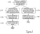
radio receiver 2 to the next usable frequency, the following scenario applies which will be described while making reference toFig. 4 . - A user scans on the
radio receiver 2 to the next usable frequency in a first step S20. Then, in a second step S21, theradio receiver 2 sends a frequency span where it currently tunes within a certain time to the powerlinecommunication network nodes 3 to 7. Then, in a third step S22, all powerlinecommunication network nodes 3 to 7 filter this frequency span in their communication band, i.e. they do not use this frequency span when communicating between the powerline communication network nodes. - The radio receiver (the tuner unit) judges in a fourth step S23, if already a new radio service has been found. If no new radio service has been found, the
radio receiver 2 chooses a new frequency span and scans this frequency span for a new usable frequency in a fifth step S24. Then, theradio receiver 2 sends the frequency span which had been last scanned for a new usable frequency to all powerlinecommunication network nodes 3 to 7 in order to free this frequency span. This is done in a sixth step S25. After this step, theradio receiver 2 returns to the second step S21 and executes the third and the fourth step S22, S23 as long a new usable frequency has been found. If this is the case, then theradio receiver 2 tunes to the radio service corresponding to the new frequency in a seventh step S26. Then, theradio receiver 2 sends the complete frequency span which was used during the tuning process to all power linecommunication network nodes 3 to 7 to reuse it (except of the frequency corresponding to the new service being played). This is done in an eighth step S27. In addition to the first step S21, theradio receiver 2 sends in a ninth step S28 the frequency span of the former user radio service (radio service which was played before the tuning process) to all powerlinecommunication network nodes 3 to 7. Then, in a tenth step S29, all powerlinecommunication network nodes 3 to 7 can use this old frequency span in their communication band again. - If the
radio receiver 2 is switched off, the scenario as described byFig. 5 applies, which will be described now. - If a user switches the radio receiver off in a first step S30, all powerline
communication network nodes 3 to 7 are informed (or notify itself) that theradio receiver 2 is no more present. In response to this information process, all power linecommunication network nodes 3 to 7 reuse the frequency span that was reserved by theradio receiver 2. This is done in a second step S31. - In the sense of the invention the term "powerline communication network" refers to an entire network, for example all powerline communication network nodes.
- As has become apparent, the
radio receiver 2 sends via its powerline communication modem 9 to all powerlinecommunication network nodes 3 to 7 the frequency span where the radio is actually tuning. This means if the radio is tuned to a fixed channel or to a range of channels in order to support alternative frequency switching, it sends the frequency of the channel(s) and the bandwidth of demodulation. If theradio receiver 2 is tuning or scanning the complete band to search for available radio stations, it sends the start and stop frequency of the scan to the powerline communication modem 9. The powerline communication modem 9 forwards the information of the frequency spectrum that has to be cleaned to all powerlinecommunication network nodes 3 to 7. All powerlinecommunication network nodes 3 to 7 have to filter this frequency span in their communication spectrum. So there are no unwanted distortions by powerline communication to radio reception. - Receivers being not aware of this invention or portable receivers may not be equipped with a powerline communication modem 9. So there may be a human interface at any other device embedded with a powerline communication modem. The user may enter the frequency and the span of the channel that the receiver is tuned to and all powerline communication modems shall not use for powerline communication.
- Additionally, there may be a selection of frequently used channels predefined in one or all powerline communication modems. So their frequencies are filtered automatically.
- Further examples are described in the following clauses:
- Clause 1: Method for operating a powerline communication network,
said powerline communication network having a radio receiver (2) and at least one powerline communication network node (3 to 7) being connected via said network with said radio receiver (2), comprising the steps of:- supplying frequency information to said at least one network node (3 to 7) of said powerline communication network, said frequency information defining the frequency span or frequency range or a plurality thereof needed by said radio receiver (2) to tune or to receive radio signals,
- wherein said network nodes (3 to 7) are operated in accordance to said frequency information so as to filter said frequency span of said radio receiver (2) and/or to communicate with each other at most at complementary frequency spans and/or at frequencies lying outside said frequency span or said frequency ranges of said radio receiver (2),
- thereby improving the reception quality of said radio receiver (2).
- Clause 2: Method according to
clause 1, wherein said frequency ranges are varied dynamically in dependence of changing frequency demands of said radio receiver (2). - Clause 3: Method according to anyone of the preceding clauses, comprising using a powerline communication modem (9) in order to connect said powerline communication network nodes (3 to 7) to said radio receiver (2) and/or to supply said frequency information to said powerline communication network nodes (3 to 7).
- Clause 4: Method according to anyone of the preceding clauses, wherein said frequency information is generated at least in part by said radio receiver (2) and then supplied to said powerline communication modem (9).
- Clause 5: Method according to anyone of the preceding clauses, wherein said frequency information is generated at least in part by or received from a user input interface (8) and then supplied to said powerline communication modem (9).
- Clause 6: Radio receiver (2) comprising
- means for generating frequency information (10) defining the frequency span or frequency range or a plurality thereof needed by said radio receiver (2) to tune or to receive radio signals,
- a powerline communication modem (9) being connected to said means for generating frequency information (10) and being adapted to be connected to at least one network node (3 to 7) of a powerline communication network,
- wherein said power line communication modem (9) is capable of forwarding said frequency information to network nodes (3 to 7) to be connected thereto.
- Clause 7: Radio receiver (2) according to
clause 6, wherein said means for generating frequency information (10) is a tuner processing unit and/or a user input interface (8). - Clause 8: Powerline communication network node (3 to 7) comprising
- means for receiving frequency information defining the frequency span or frequency range or a plurality thereof and
- comprising means for adapting its operation in accordance to said frequency information so as to filter said frequency span and/or to communicate only at complementary frequency spans and/or at frequencies lying outside said frequency span or said frequency ranges.
- Clause 9: Communication system (1), comprising:
- a radio receiver (2) according to any one of
clauses 6 and 7, - at least one powerline communication network node (3 to 7) being part of a powerline communication network according to clause 8,
- wherein said powerline communication modem (9) is connected to said at least one powerline communication network node (3 to 7) via said powerline communication network.
- a radio receiver (2) according to any one of
- Clause 10: Computer program product comprising computer program means adapted to perform or realize the method according to anyone of the
clauses 1 to 5 when it is executed on a computer, a digital signal processing means or the like. - Clause 11: Computer readable storage means adapted to store a computer program product according to
clause 10.
Claims (10)
- Method for operating a powerline communication network on the basis of frequency ranges coinciding with frequency ranges also used by radio receivers (2), said powerline communication network having powerline communication network nodes (3 to 7) being connected via said network, the method comprising the steps of:- supplying frequency reuse information by using the powerline communication network to said network nodes (3 to 7) of said powerline communication network, said frequency reuse information defining a frequency range previously reserved for use by said radio receivers to receive radio signals and wherein said network nodes were previously operated so as to communicate with each other at frequencies lying outside said frequency range of said radio receivers,- wherein said network nodes (3 to 7) are currently operated in accordance to said frequency reuse information so as to communicate with each other at frequencies indicated by the frequency reuse information.
- Method according to anyone of the preceding claims,
characterized by
using a powerline communication modem (9) in order to connect said powerline communication network nodes (3 to 7) to a radio receiver (2) of said radio receivers to supply said frequency reuse information to said powerline communication network nodes (3 to 7). - Method according to anyone of the preceding claims,
characterized in that
said frequency reuse information is generated at least in part by a radio receiver (2) of said radio receivers and then supplied to said powerline communication modem (9). - Method according to anyone of the preceding claims,
characterized in that
said frequency reuse information is generated at least in part by or received from a user input interface (8) and then supplied to said powerline communication modem (9). - Radio receiver (2),
comprising- means for generating frequency reuse information (10) indicative of frequencies lying within a frequency range previously used by radio receivers and to be frequency reused for powerline communication,- a powerline communication modem (9) being connected to said means for generating frequency reuse information (10) and being adapted to be connected to network nodes (3 to 7) of a powerline communication network,- wherein said power line communication modem (9) is adapted to forward said frequency reuse information to said network nodes (3 to 7) to be connected thereto, so that said network nodes (3 to 7) are operated in accordance to said frequency reuse information so as to communicate with each other at frequencies indicated by the frequency reuse information. - Radio receiver (2) according to claim 5,
characterized in that
said means for generating frequency reuse information (10) is a tuner processing unit (10). - Powerline communication network node (3 to 7) configured to be part of a powerline communication network having powerline communication network nodes (3 to 7) being connected via said network, said network operating on the basis of frequency ranges coinciding with frequency ranges also used by radio receivers,
comprising:- means for receiving frequency reuse information by using the powerline communication network indicative of frequencies lying within a frequency range previously used by radio receivers and to be reused for powerline communication by said network nodes, said frequency reuse information defining a frequency range previously reserved for use by said radio receivers to receive radio signals and wherein said network nodes were previously operated so as to communicate with each other at frequencies lying outside said frequency range of said radio receivers,- comprising means for adapting its operation in accordance to said frequency reuse information so as to communicate with other powerline communication network nodes (3 to 7) at frequencies indicated by the frequency reuse information. - Communication system (1).
comprising:- the radio receiver (2) according to any one of claims 5 and 6,- at least one powerline communication network node (3 to 7) according to claim 7.- wherein said powerline communication modem (9) is connected to said at least one powerline communication network node (3 to 7) via a powerline communication network. - Computer program product comprising computer program means adapted to perform or realize the method according to anyone of the claims 1 to 4 when executed on a computer.
- Computer readable storage means adapted to store the computer program product according to claim 9.
Priority Applications (1)
| Application Number | Priority Date | Filing Date | Title |
|---|---|---|---|
| EP17162408.3A EP3203644B1 (en) | 2002-10-11 | 2002-10-11 | Method for operating a powerline communication network |
Applications Claiming Priority (2)
| Application Number | Priority Date | Filing Date | Title |
|---|---|---|---|
| EP17162408.3A EP3203644B1 (en) | 2002-10-11 | 2002-10-11 | Method for operating a powerline communication network |
| EP02022807.8A EP1408622B1 (en) | 2002-10-11 | 2002-10-11 | Method for operating a powerline communication network |
Related Parent Applications (2)
| Application Number | Title | Priority Date | Filing Date |
|---|---|---|---|
| EP02022807.8A Division-Into EP1408622B1 (en) | 2002-10-11 | 2002-10-11 | Method for operating a powerline communication network |
| EP02022807.8A Division EP1408622B1 (en) | 2002-10-11 | 2002-10-11 | Method for operating a powerline communication network |
Publications (2)
| Publication Number | Publication Date |
|---|---|
| EP3203644A1 EP3203644A1 (en) | 2017-08-09 |
| EP3203644B1 true EP3203644B1 (en) | 2019-07-17 |
Family
ID=32010969
Family Applications (2)
| Application Number | Title | Priority Date | Filing Date |
|---|---|---|---|
| EP02022807.8A Expired - Lifetime EP1408622B1 (en) | 2002-10-11 | 2002-10-11 | Method for operating a powerline communication network |
| EP17162408.3A Expired - Lifetime EP3203644B1 (en) | 2002-10-11 | 2002-10-11 | Method for operating a powerline communication network |
Family Applications Before (1)
| Application Number | Title | Priority Date | Filing Date |
|---|---|---|---|
| EP02022807.8A Expired - Lifetime EP1408622B1 (en) | 2002-10-11 | 2002-10-11 | Method for operating a powerline communication network |
Country Status (1)
| Country | Link |
|---|---|
| EP (2) | EP1408622B1 (en) |
Family Cites Families (4)
| Publication number | Priority date | Publication date | Assignee | Title |
|---|---|---|---|---|
| US4479215A (en) * | 1982-09-24 | 1984-10-23 | General Electric Company | Power-line carrier communications system with interference avoidance capability |
| JPS61101126A (en) * | 1984-10-23 | 1986-05-20 | Matsushita Electric Ind Co Ltd | Carrier superimposing communication equipment |
| GB9407934D0 (en) * | 1994-04-21 | 1994-06-15 | Norweb Plc | Transmission network and filter therefor |
| GB9828373D0 (en) * | 1998-12-22 | 1999-02-17 | Northern Telecom Ltd | A power line communication system and method of operation thereof |
-
2002
- 2002-10-11 EP EP02022807.8A patent/EP1408622B1/en not_active Expired - Lifetime
- 2002-10-11 EP EP17162408.3A patent/EP3203644B1/en not_active Expired - Lifetime
Non-Patent Citations (1)
| Title |
|---|
| None * |
Also Published As
| Publication number | Publication date |
|---|---|
| EP1408622B1 (en) | 2017-07-26 |
| EP1408622A1 (en) | 2004-04-14 |
| EP3203644A1 (en) | 2017-08-09 |
Similar Documents
| Publication | Publication Date | Title |
|---|---|---|
| US6195563B1 (en) | Radio receiver and radio transmitter | |
| JP3348196B2 (en) | Wireless transmission system | |
| CN1135687C (en) | Frequency synthesizer circuit for mobile stations | |
| EP2140555B1 (en) | Method and apparatus for adaptive channel utilisation | |
| US20080233954A1 (en) | Method And System For Processing Results Derived From Detecting Channels Suitable For FM Transmission In An Integrated FM Transmit/Receive System | |
| KR20010033776A (en) | Method and arrangement in radio communication networks | |
| US6628927B1 (en) | Method and apparatus for transmitting and receiving signals | |
| ZA200604501B (en) | Method and apparatus for establishing direct mobile to mobile communication between cellular mobile terminals | |
| WO1998043366A1 (en) | Dual band mobile station | |
| JPH05327569A (en) | Diversity transmission/reception system | |
| US5999823A (en) | Cellular cordless telephone | |
| JPH11331026A (en) | Double band mobile telephone hand set | |
| JP2001519135A (en) | Method and apparatus for efficient wireless transmission of data | |
| EP3203644B1 (en) | Method for operating a powerline communication network | |
| CA2306485A1 (en) | Dual mode mobile telephone | |
| JP2000269848A (en) | Multi-mode radio communication converter and communication method using the same | |
| JP2002101032A (en) | Gap filler for ground-wave digital broadcasting | |
| KR100302096B1 (en) | Vehicle remote controller using the mobile communication terminal | |
| US20040214544A1 (en) | Apparatus and method for the avoidance of RF interference | |
| US20040121744A1 (en) | Method and apparatus for producing mobile radio signals | |
| EP1240721B1 (en) | Frequency generation for cdma terminal with slotted receive mode | |
| JP2000341188A (en) | Radio communications equipment and radio communication method | |
| JP3559138B2 (en) | Two-way communication equipment | |
| JP4191230B2 (en) | Bidirectional communication device | |
| JP2011166420A (en) | Cellular phone set with television broadcast receiving function, and control method thereof |
Legal Events
| Date | Code | Title | Description |
|---|---|---|---|
| PUAI | Public reference made under article 153(3) epc to a published international application that has entered the european phase |
Free format text: ORIGINAL CODE: 0009012 |
|
| 17P | Request for examination filed |
Effective date: 20170322 |
|
| AC | Divisional application: reference to earlier application |
Ref document number: 1408622 Country of ref document: EP Kind code of ref document: P |
|
| AK | Designated contracting states |
Kind code of ref document: A1 Designated state(s): DE FR GB |
|
| 17Q | First examination report despatched |
Effective date: 20180103 |
|
| GRAP | Despatch of communication of intention to grant a patent |
Free format text: ORIGINAL CODE: EPIDOSNIGR1 |
|
| INTG | Intention to grant announced |
Effective date: 20181019 |
|
| GRAJ | Information related to disapproval of communication of intention to grant by the applicant or resumption of examination proceedings by the epo deleted |
Free format text: ORIGINAL CODE: EPIDOSDIGR1 |
|
| INTC | Intention to grant announced (deleted) | ||
| GRAP | Despatch of communication of intention to grant a patent |
Free format text: ORIGINAL CODE: EPIDOSNIGR1 |
|
| INTG | Intention to grant announced |
Effective date: 20190225 |
|
| GRAS | Grant fee paid |
Free format text: ORIGINAL CODE: EPIDOSNIGR3 |
|
| GRAA | (expected) grant |
Free format text: ORIGINAL CODE: 0009210 |
|
| AC | Divisional application: reference to earlier application |
Ref document number: 1408622 Country of ref document: EP Kind code of ref document: P |
|
| AK | Designated contracting states |
Kind code of ref document: B1 Designated state(s): DE FR GB |
|
| REG | Reference to a national code |
Ref country code: GB Ref legal event code: FG4D |
|
| REG | Reference to a national code |
Ref country code: DE Ref legal event code: R096 Ref document number: 60249955 Country of ref document: DE |
|
| REG | Reference to a national code |
Ref country code: DE Ref legal event code: R097 Ref document number: 60249955 Country of ref document: DE |
|
| PLBE | No opposition filed within time limit |
Free format text: ORIGINAL CODE: 0009261 |
|
| STAA | Information on the status of an ep patent application or granted ep patent |
Free format text: STATUS: NO OPPOSITION FILED WITHIN TIME LIMIT |
|
| 26N | No opposition filed |
Effective date: 20200603 |
|
| PGFP | Annual fee paid to national office [announced via postgrant information from national office to epo] |
Ref country code: FR Payment date: 20210921 Year of fee payment: 20 |
|
| PGFP | Annual fee paid to national office [announced via postgrant information from national office to epo] |
Ref country code: GB Payment date: 20210922 Year of fee payment: 20 |
|
| PGFP | Annual fee paid to national office [announced via postgrant information from national office to epo] |
Ref country code: DE Payment date: 20210921 Year of fee payment: 20 |
|
| REG | Reference to a national code |
Ref country code: DE Ref legal event code: R071 Ref document number: 60249955 Country of ref document: DE |
|
| REG | Reference to a national code |
Ref country code: GB Ref legal event code: PE20 Expiry date: 20221010 |
|
| PG25 | Lapsed in a contracting state [announced via postgrant information from national office to epo] |
Ref country code: GB Free format text: LAPSE BECAUSE OF EXPIRATION OF PROTECTION Effective date: 20221010 |