EP3203562A1 - Fuel cell system - Google Patents
Fuel cell system Download PDFInfo
- Publication number
- EP3203562A1 EP3203562A1 EP17151564.6A EP17151564A EP3203562A1 EP 3203562 A1 EP3203562 A1 EP 3203562A1 EP 17151564 A EP17151564 A EP 17151564A EP 3203562 A1 EP3203562 A1 EP 3203562A1
- Authority
- EP
- European Patent Office
- Prior art keywords
- water
- reforming
- pump
- fuel cell
- plunger
- Prior art date
- Legal status (The legal status is an assumption and is not a legal conclusion. Google has not performed a legal analysis and makes no representation as to the accuracy of the status listed.)
- Granted
Links
- 239000000446 fuel Substances 0.000 title claims abstract description 107
- XLYOFNOQVPJJNP-UHFFFAOYSA-N water Substances O XLYOFNOQVPJJNP-UHFFFAOYSA-N 0.000 claims abstract description 654
- 238000001704 evaporation Methods 0.000 claims abstract description 31
- 238000002407 reforming Methods 0.000 claims description 86
- 239000000463 material Substances 0.000 claims description 19
- 230000005540 biological transmission Effects 0.000 claims description 8
- 239000007800 oxidant agent Substances 0.000 claims description 7
- 230000001590 oxidative effect Effects 0.000 claims description 7
- 238000007599 discharging Methods 0.000 claims description 3
- 239000007789 gas Substances 0.000 description 29
- 238000010248 power generation Methods 0.000 description 11
- VNWKTOKETHGBQD-UHFFFAOYSA-N methane Chemical compound C VNWKTOKETHGBQD-UHFFFAOYSA-N 0.000 description 10
- 239000000567 combustion gas Substances 0.000 description 9
- 238000004891 communication Methods 0.000 description 7
- 230000007423 decrease Effects 0.000 description 6
- 238000001514 detection method Methods 0.000 description 6
- 230000035515 penetration Effects 0.000 description 5
- 239000003054 catalyst Substances 0.000 description 4
- UGFAIRIUMAVXCW-UHFFFAOYSA-N Carbon monoxide Chemical compound [O+]#[C-] UGFAIRIUMAVXCW-UHFFFAOYSA-N 0.000 description 3
- OKKJLVBELUTLKV-UHFFFAOYSA-N Methanol Chemical compound OC OKKJLVBELUTLKV-UHFFFAOYSA-N 0.000 description 3
- 230000001133 acceleration Effects 0.000 description 3
- 229910002091 carbon monoxide Inorganic materials 0.000 description 3
- 230000008014 freezing Effects 0.000 description 3
- 238000007710 freezing Methods 0.000 description 3
- 239000003345 natural gas Substances 0.000 description 3
- 238000006057 reforming reaction Methods 0.000 description 3
- CURLTUGMZLYLDI-UHFFFAOYSA-N Carbon dioxide Chemical compound O=C=O CURLTUGMZLYLDI-UHFFFAOYSA-N 0.000 description 2
- 238000010586 diagram Methods 0.000 description 2
- 239000003792 electrolyte Substances 0.000 description 2
- 150000002431 hydrogen Chemical class 0.000 description 2
- 229910052739 hydrogen Inorganic materials 0.000 description 2
- 239000001257 hydrogen Substances 0.000 description 2
- 239000007788 liquid Substances 0.000 description 2
- 230000010355 oscillation Effects 0.000 description 2
- 238000005192 partition Methods 0.000 description 2
- 230000002093 peripheral effect Effects 0.000 description 2
- 238000011084 recovery Methods 0.000 description 2
- 239000007787 solid Substances 0.000 description 2
- NWUYHJFMYQTDRP-UHFFFAOYSA-N 1,2-bis(ethenyl)benzene;1-ethenyl-2-ethylbenzene;styrene Chemical compound C=CC1=CC=CC=C1.CCC1=CC=CC=C1C=C.C=CC1=CC=CC=C1C=C NWUYHJFMYQTDRP-UHFFFAOYSA-N 0.000 description 1
- UFHFLCQGNIYNRP-UHFFFAOYSA-N Hydrogen Chemical compound [H][H] UFHFLCQGNIYNRP-UHFFFAOYSA-N 0.000 description 1
- 229910002092 carbon dioxide Inorganic materials 0.000 description 1
- 239000001569 carbon dioxide Substances 0.000 description 1
- 238000006243 chemical reaction Methods 0.000 description 1
- 238000009833 condensation Methods 0.000 description 1
- 230000005494 condensation Effects 0.000 description 1
- 239000008367 deionised water Substances 0.000 description 1
- 229910021641 deionized water Inorganic materials 0.000 description 1
- 239000003502 gasoline Substances 0.000 description 1
- 230000002401 inhibitory effect Effects 0.000 description 1
- 239000003456 ion exchange resin Substances 0.000 description 1
- 229920003303 ion-exchange polymer Polymers 0.000 description 1
- 239000003350 kerosene Substances 0.000 description 1
- 238000003475 lamination Methods 0.000 description 1
- 239000003915 liquefied petroleum gas Substances 0.000 description 1
- 230000007257 malfunction Effects 0.000 description 1
- 238000000034 method Methods 0.000 description 1
- 239000000203 mixture Substances 0.000 description 1
- RVTZCBVAJQQJTK-UHFFFAOYSA-N oxygen(2-);zirconium(4+) Chemical compound [O-2].[O-2].[Zr+4] RVTZCBVAJQQJTK-UHFFFAOYSA-N 0.000 description 1
- 239000011800 void material Substances 0.000 description 1
- 229910001928 zirconium oxide Inorganic materials 0.000 description 1
Images



Classifications
-
- H—ELECTRICITY
- H01—ELECTRIC ELEMENTS
- H01M—PROCESSES OR MEANS, e.g. BATTERIES, FOR THE DIRECT CONVERSION OF CHEMICAL ENERGY INTO ELECTRICAL ENERGY
- H01M8/00—Fuel cells; Manufacture thereof
- H01M8/04—Auxiliary arrangements, e.g. for control of pressure or for circulation of fluids
- H01M8/04223—Auxiliary arrangements, e.g. for control of pressure or for circulation of fluids during start-up or shut-down; Depolarisation or activation, e.g. purging; Means for short-circuiting defective fuel cells
- H01M8/04253—Means for solving freezing problems
-
- H—ELECTRICITY
- H01—ELECTRIC ELEMENTS
- H01M—PROCESSES OR MEANS, e.g. BATTERIES, FOR THE DIRECT CONVERSION OF CHEMICAL ENERGY INTO ELECTRICAL ENERGY
- H01M8/00—Fuel cells; Manufacture thereof
- H01M8/04—Auxiliary arrangements, e.g. for control of pressure or for circulation of fluids
- H01M8/04291—Arrangements for managing water in solid electrolyte fuel cell systems
-
- H—ELECTRICITY
- H01—ELECTRIC ELEMENTS
- H01M—PROCESSES OR MEANS, e.g. BATTERIES, FOR THE DIRECT CONVERSION OF CHEMICAL ENERGY INTO ELECTRICAL ENERGY
- H01M8/00—Fuel cells; Manufacture thereof
- H01M8/04—Auxiliary arrangements, e.g. for control of pressure or for circulation of fluids
- H01M8/04298—Processes for controlling fuel cells or fuel cell systems
- H01M8/04313—Processes for controlling fuel cells or fuel cell systems characterised by the detection or assessment of variables; characterised by the detection or assessment of failure or abnormal function
- H01M8/04492—Humidity; Ambient humidity; Water content
-
- H—ELECTRICITY
- H01—ELECTRIC ELEMENTS
- H01M—PROCESSES OR MEANS, e.g. BATTERIES, FOR THE DIRECT CONVERSION OF CHEMICAL ENERGY INTO ELECTRICAL ENERGY
- H01M8/00—Fuel cells; Manufacture thereof
- H01M8/06—Combination of fuel cells with means for production of reactants or for treatment of residues
- H01M8/0606—Combination of fuel cells with means for production of reactants or for treatment of residues with means for production of gaseous reactants
- H01M8/0612—Combination of fuel cells with means for production of reactants or for treatment of residues with means for production of gaseous reactants from carbon-containing material
- H01M8/0618—Reforming processes, e.g. autothermal, partial oxidation or steam reforming
-
- Y—GENERAL TAGGING OF NEW TECHNOLOGICAL DEVELOPMENTS; GENERAL TAGGING OF CROSS-SECTIONAL TECHNOLOGIES SPANNING OVER SEVERAL SECTIONS OF THE IPC; TECHNICAL SUBJECTS COVERED BY FORMER USPC CROSS-REFERENCE ART COLLECTIONS [XRACs] AND DIGESTS
- Y02—TECHNOLOGIES OR APPLICATIONS FOR MITIGATION OR ADAPTATION AGAINST CLIMATE CHANGE
- Y02E—REDUCTION OF GREENHOUSE GAS [GHG] EMISSIONS, RELATED TO ENERGY GENERATION, TRANSMISSION OR DISTRIBUTION
- Y02E60/00—Enabling technologies; Technologies with a potential or indirect contribution to GHG emissions mitigation
- Y02E60/30—Hydrogen technology
- Y02E60/50—Fuel cells
Definitions
- the water tank includes a water level sensor detecting a water level of the water for reforming stored at the water tank.
- the control unit includes a drainage determination portion determining whether or not the water for reforming at the primary side of the water pump is discharged on a basis of a water level of the water for reforming stored at the water tank.
- the water removal control portion executes the water removal control in a case where the drainage determination portion determines that the water for reforming at the primary side of the water pump is discharged.
- the inverter device 13 receives a direct-current (DC) voltage output from the fuel cell 34 and converts the DC voltage into a predetermined alternating-current (AC) voltage so as to output the AC voltage to a power line 16b connected to an alternating system power supply 16a (hereinafter simply referred to as a system power supply 16a) and to an external electric power load 16c such as an electrical appliance, for example.
- the inverter device 13 also receives an AC voltage from the system power supply 16a via the power line 16b and converts the AC voltage into a predetermined DC voltage so as to output the DC voltage to an auxiliary machinery (each pump or blower) and the control unit 15.
- the control unit 15 drives the auxiliary machinery to thereby control the operation of the fuel cell system 1.
- the reforming portion 33 generates reformed gas from mixed gas (source material and water vapor) supplied from the evaporating portion 32 and discharges the reformed gas while being heated by the combustion gas so as to receive heat necessary for a water vapor reforming reaction.
- the inside of the reforming portion 33 is filled with a catalyst, for example, with a Ru catalyst or a Ni catalyst.
- the mixed gas supplied from the evaporating portion 32 reacts by means of the catalyst so as to be reformed, thereby generating hydrogen gas and gas containing carbon monoxide, for example (so-called a water vapor reforming reaction).
- a combusting portion 36 is disposed among the fuel cell 34, the evaporating portion 32 and the reforming portion 33.
- the combusting portion 36 heats the evaporating portion 32 and the reforming portion 33 by burning anode off-gas (fuel off-gas) from the fuel cell 34 and cathode off-gas (oxidant off-gas) from the fuel cell 34.
- the fuel cell system 1 is constructed in the aforementioned manner so that a secondary side of the water pump 40 is connected to the outside of the case 10a via the water supply pipe 11b, the evaporating portion 32, the reforming portion 33, the reformed gas supply pipe 38, the manifold 35, the fuel flow passage 34b of the fuel cell 34, the combusting portion 36 and the exhaust pipe 11d. That is, the secondary side of the water pump 40 is connected to the air.
- the control unit 15 performs the water removal control in a case where the fuel cell system 1 is in a standby state.
- the standby state corresponds to a power generation stop state of the fuel cell system 1, i.e., a state where the fuel cell system 1 is inhibited from performing a startup operation, a power generation operation or a stop operation. That is, the fuel cell system 1 is in a state waiting a power generation instruction such as turning-on of a start switch, for example.
- a power generation instruction such as turning-on of a start switch, for example.
- the warning indicating that the water removal is not completed is made (step S116, the warning portion 15f). Because the secondary side of the water pump 40 is in communication with the air as mentioned above, the secondary side of the water pump 40 is not airtightly sealed. Thus, at the secondary side of the water pump 40, a damage or a breakage of the water pump 40 or the water supply pipe 11b is inhibited from occurring even when the water flowing out from the pump chamber PR is frozen so as to increase the volume of the water.
- the fuel cell system 1 includes the fuel cell 34 generating the electric power by the fuel and the oxidant gas, the evaporating portion 32 generating the water vapor from the water for reforming, the reforming portion 33 generating the fuel by the source material for reforming and the water vapor to supply the fuel to the fuel cell 34, the water tank 14 storing the water for reforming, the water pump 40 supplying the water for reforming which is stored at the water tank 14 to the evaporating portion 32, the drainage mechanical portion 17 discharging the water for reforming at the primary side of the water pump 40 to the outside and the control unit 15 controlling at least the driving amount of the water pump 40.
Landscapes
- Life Sciences & Earth Sciences (AREA)
- Engineering & Computer Science (AREA)
- Manufacturing & Machinery (AREA)
- Sustainable Development (AREA)
- Sustainable Energy (AREA)
- Chemical & Material Sciences (AREA)
- Chemical Kinetics & Catalysis (AREA)
- Electrochemistry (AREA)
- General Chemical & Material Sciences (AREA)
- Fuel Cell (AREA)
Abstract
Description
- This disclosure generally relates to a fuel cell system.
- A known fuel cell system is disclosed, for example, in
WO2010125734A which is hereinafter referred to as Reference 1. The fuel cell system disclosed in Reference 1 includes a water circulation passage where water required for an operation of the fuel cell system circulates. The water circulation passage is divided into plural blocks at which drain valves are provided respectively so that a drain process is achievable per block in the plural blocks. - In the fuel cell system disclosed in Reference 1, in a case where a pump which circulates water for reforming is provided with a check valve, it is considerable that the water within the pump is not discharged and remains within the pump. In a case where the water within the pump is not discharged to the outside of the pump, the pump may be damaged due to freezing of the water within the pump.
- A need thus exists for a fuel cell system including a pump from which water is removable even in a case where a check valve is provided at the pump.
- According to an aspect of this disclosure, a fuel cell system includes a fuel cell generating electric power by fuel and oxidant gas, an evaporating portion generating water vapor from water for reforming, a reforming portion generating the fuel by source material for reforming and the water vapor to supply the fuel to the fuel cell, a water tank storing the water for reforming, a water pump supplying the water for reforming which is stored at the water tank to the evaporating portion, a drainage mechanical portion discharging the water for reforming at a primary side of the water pump to an outside, and a control unit controlling at least a driving amount of the water pump. The water pump includes a housing, a first flow passage provided at the housing to connect between a pump chamber within the housing and an inlet opening to which the water for reforming from the water tank flows, a second flow passage provided at the housing to connect between the pump chamber and an outlet opening out of which the water for reforming from the pump chamber flows, a first check valve provided at the first flow passage to permit a flow of the water for reforming in a first direction in which the water for reforming flows from the water tank towards the evaporating portion and to restrict the flow of the water for reforming in an opposite direction from the first direction, and a second check valve provided at the second flow passage to permit the flow of the water for reforming in the first direction and to restrict the flow of the water for reforming in the opposite direction from the first direction. The control unit includes a water removal control portion which executes a water removal control for removing the water for reforming from the water pump by driving the water pump by a predetermined driving amount in a case where the water for reforming at the primary side of the water pump is discharged by the drainage mechanical portion.
- In the water pump, the first and second check valves are provided at the first flow passage and the second flow passage respectively. Thus, in a case where a supply of the water for reforming to the evaporating portion is stopped, the water remains within the pump chamber. Then, in a case where the water at the primary side of the water pump is discharged, the control unit performs the water removal control. According to the water removal control, the water is removed from the water pump by driving the water pump by the predetermined driving amount. When the water at the primary side of the water pump is discharged, the primary side of the water pump is in communication with air. The first check valve is opened by the driving of the water pump by the water removal control and the air at the primary side of the water pump flows into the pump chamber via the first flow passage from the inlet opening. Further, the water within the pump chamber flows to the second flow passage to open the second check valve and flows out from the outlet opening. The water removal from the water pump is thus performed. Even in a case where the check valves are provided at the water pump, the water removal from the water pump is achievable.
- The water tank includes a water level sensor detecting a water level of the water for reforming stored at the water tank. The control unit includes a drainage determination portion determining whether or not the water for reforming at the primary side of the water pump is discharged on a basis of a water level of the water for reforming stored at the water tank. The water removal control portion executes the water removal control in a case where the drainage determination portion determines that the water for reforming at the primary side of the water pump is discharged.
- Accordingly, the control unit may determine that the water at the primary side of the water pump is discharged on a basis of a detection result of the water level sensor. Thus, the control unit performs the water removal control in a case where the water at the primary side of the water pump is discharged and the primary side of the water pump is in communication with the air. The water removal from the water pump may be thus securely performed.
- The water pump is a plunger pump where the water for reforming stored at the water tank flows into the pump chamber from the inlet opening and the water for reforming within the pump chamber flows out from the outlet opening by a change in volume of the pump chamber based on a reciprocation of a plunger.
- Accordingly, even in a case where the water pump is the plunger pump, the control unit may perform the water removal from the water pump.
- The water pump generates a vibration by a collision of the plunger with a collided portion with which the plunger is collided during the reciprocation of the plunger. The control unit includes a water removal determination portion which determines whether or not the removal of the water for reforming from the water pump is completed by the water removal control based on a magnitude of the vibration detected by a vibration detector which is provided at a transmission portion to which the vibration is transmitted, the transmission portion being arranged at the housing.
- Accordingly, in a case where a detected vibration value detected by the vibration detector is equal to or greater than a vibration determination value, the control unit may determine that the water removal from the water pump is completed by the water removal control. Thus, the control unit securely restrains occurrence of a damage of the water pump caused by freezing of the water within the pump chamber.
- The foregoing and additional features and characteristics of this disclosure will become more apparent from the following detailed description considered with the reference to the accompanying drawings, wherein:
-
Fig. 1 is a schematic view illustrating a fuel cell system according to a first embodiment disclosed here; -
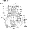
Fig. 2 is an axially cross-sectional view illustrating a water pump illustrated inFig. 1 in a state where a coil is not supplied with electric power; -
Fig. 3 is an axially cross-sectional view illustrating the water pump illustrated inFig. 1 in a state where the coil is supplied with the electric power; -
Fig. 4 is a block diagram of the fuel cell system illustrated inFig. 1 ; -
Fig. 5 is a flowchart of a control program performed by a control unit illustrated inFig. 4 ; -
Fig. 6 is a time-chart illustrating an operation of the fuel cell system operated on a basis of the flowchart inFig. 5 ; -
Fig. 7 is a block diagram of the fuel cell system according to a second embodiment disclosed here; and -
Fig. 8 is a schematic view illustrating a drainage mechanical portion according to a modified example of the first and second embodiments. - A first embodiment of a fuel cell system is explained with reference to
Figs. 1 to 6 . In the disclosure, for convenience, the explanation is made under conditions where an upper side in each ofFigs. 1 to 3 corresponds to an upper side of a fuel cell system 1 while a lower side in each ofFigs. 1 to 3 corresponds to a lower side of the fuel cell system 1. As illustrated inFig. 1 , the fuel cell system 1 includes apower generation unit 10 and awater storage tank 21 which stores water (hot or warmed water). Thepower generation unit 10 includes acase 10a, afuel cell module 11, aheat exchanger 12, aninverter device 13, awater tank 14 and acontrol unit 15. - The
fuel cell module 11 is configured to include at least afuel cell 34. Thefuel cell module 11 is supplied with a source material for reforming (source material), water for reforming (water) and cathode air. Specifically, thefuel cell module 11 is connected to a first end of a sourcematerial supply pipe 11a of which a second end is connected to a supply source Gs so that the sourcematerial supply pipe 11a is supplied with the source material. A source material pump 11a1 which pumps the source material is provided at the sourcematerial supply pipe 11a. Thefuel cell module 11 is also connected to a first end of awater supply pipe 11b of which a second end is connected to thewater tank 14 so that thewater supply pipe 11b is supplied with the water. Thewater tank 14 stores the water for reforming. Awater pump 40 which is explained later is disposed at thewater supply pipe 11b. Thefuel cell module 11 is further connected to a first end of a cathodeair supply pipe 11c of which a second end is connected to a cathode air blower 11c1 so that the cathodeair supply pipe 11c is supplied with the cathode air. - The
heat exchanger 12 is supplied with exhaust combustion gas emitted or discharged from thefuel cell module 11 and with storage water stored at thewater storage tank 21 to perform a heat exchange between the exhaust combustion gas and the storage water. Specifically, thewater storage tank 21 which stores water (hot or warmed water) serving as the storage water is connected to a storagewater circulation line 22 where the water (storage water) circulates in a direction indicated by arrows inFig. 1 . A storagewater circulation pump 22a and theheat exchanger 12 are arranged at the storagewater circulation line 22 in the mentioned order from a lower end to an upper end of thewater storage tank 21. Anexhaust pipe 11d which extends from thefuel cell module 11 is connected to theheat exchanger 12 in a penetration manner. A condensedwater supply pipe 12a which is connected to thewater tank 14 is connected to theheat exchanger 12. - The exhaust combustion gas from the
fuel cell module 11 is led to theheat exchanger 12 by flowing through theexhaust pipe 11d and is condensed and cooled at theheat exchanger 12 because of the heat exchange with the storage water. The exhaust combustion gas after condensation flows through theexhaust pipe 11d to be discharged to the outside of thecase 10a. Condensed water resulting from the aforementioned heat exchange flows through the condensedwater supply pipe 12a so as to be supplied to thewater tank 14. Thewater tank 14 brings the condensed water to be formed into pure water (deionized water) by means of ion-exchange resin. - The
heat exchanger 12, thewater storage tank 21 and the storagewater circulation line 22 constitute an exhaustheat recovery system 20. The exhaustheat recovery system 20 recovers exhaust heat of thefuel cell module 11 and stores the exhaust heat in the storage water. - The
inverter device 13 receives a direct-current (DC) voltage output from thefuel cell 34 and converts the DC voltage into a predetermined alternating-current (AC) voltage so as to output the AC voltage to apower line 16b connected to an alternatingsystem power supply 16a (hereinafter simply referred to as asystem power supply 16a) and to an externalelectric power load 16c such as an electrical appliance, for example. Theinverter device 13 also receives an AC voltage from thesystem power supply 16a via thepower line 16b and converts the AC voltage into a predetermined DC voltage so as to output the DC voltage to an auxiliary machinery (each pump or blower) and thecontrol unit 15. Thecontrol unit 15 drives the auxiliary machinery to thereby control the operation of the fuel cell system 1. - The
fuel cell module 11 includes acasing 31, an evaporatingportion 32, a reformingportion 33 and thefuel cell 34. Thecasing 31 in a box form is made of an insulative material. The evaporatingportion 32 which is heated by combustion gas (which is explained later) generates water vapor by evaporating the water (water for reforming) supplied to the evaporatingportion 32. The evaporatingportion 32 also preheats the source material supplied to the evaporatingportion 32. The evaporatingportion 32 mixes the water vapor generated in the aforementioned manner and the source material that is preheated so as to supply the mixture to the reformingportion 33. The source material corresponds to gaseous fuel (gaseous fuel for reforming) such as natural gas and liquefied petroleum gas (LP gas), for example, and liquid fuel (liquid fuel for reforming) such as kerosene, gasoline (petrol) and methanol, for example. In the present present embodiment, the source material is the natural gas. - The evaporating
portion 32 is connected to the first end of the sourcematerial supply pipe 11a of which the second end is connected to the supply source Gs. The supply source Gs corresponds to a city gas supply pipe or an LP gas cylinder, for example. In addition, the evaporatingportion 32 is connected to the first end of thewater supply pipe 11b of which the second end is connected to thewater tank 14. Thewater pump 40 is disposed at thewater supply pipe 11b. Thewater pump 40 is arranged at an upper side than a connection portion of thewater supply pipe 11b relative to thewater tank 14. - The
water pump 40 supplies the water (water for reforming) stored at thewater tank 14 to the evaporatingportion 32. Thewater pump 40 serves as a plunger pump. As illustrated inFig. 2 , thewater pump 40 includes afirst housing 41, asecond housing 42, acoil 43 in a tubular form, aplunger 44 and aspring 45. Each of thefirst housing 41 and thesecond housing 42 serves as a housing. - The
first housing 41 includes abody portion 41a, aflange portion 41b, afirst check valve 41c and asecond check valve 41d. Thebody portion 41a is cylindrically formed extending in a direction of an axis 41a1. Thebody portion 41a includes an inlet opening 41a2, an outlet opening 41a3, a first flow passage 41a4 and a second flow passage 41a5. The inlet opening 41a2 is provided at the first housing 41 (specifically, thebody portion 41a) to serve as an opening portion to which the water from thewater tank 14 flows. The inlet opening 41a2 is connected to thewater tank 14 via thewater supply pipe 11b. The outlet opening 41a3 is provided at the first housing 41 (specifically, thebody portion 41a) to serve as an opening portion from which the water from a pump chamber PR (which is explained later) arranged within thebody portion 41a flows. The outlet opening 41a3 is connected to the evaporatingportion 32 via thewater supply pipe 11b. - The first flow passage 41a4 is provided at the first housing 41 (specifically, the
body portion 41a) to connect between the inlet opening 41a2 and the pump chamber PR. The second flow passage 41a5 is provided at the first housing 41 (specifically, thebody portion 41a) to connect between the pump chamber PR and the outlet opening 41a3. Theflange portion 41b is provided at an upper end portion of thebody portion 41a so as to protrude radially outward over an entire circumference relative to the axis 41a1 of thebody portion 41a. - The
first check valve 41c, which is provided at the first flow passage 41a4, permits or enables a flow of the water in a direction in which the water flows from thewater tank 14 to the evaporatingportion 32 and prohibits or restricts the flow of the water in an opposite direction from the first direction. Specifically, thefirst check valve 41c permits the flow of the water to the pump chamber PR from the inlet opening 41a2 and prohibits the flow of the water to the inlet opening 41a2 from the pump chamber PR. - The
first check valve 41c includes a first holding plate 41c1, a first spring 41c2, a first valve body 41c3 and a first valve seat 41c4 in the mentioned order from an upper side to a lower side inFig. 2 . A penetration hole 41c1a through which the water may flow is provided at the first holding plate 41c1. The first spring 41c2 is held at the first holding plate 41c1. The first valve body 41c3 in a spherical form is biased by the first spring 41c2. InFig. 2 , the first valve seat 41c4 is provided at an upper-side opening edge of a penetration hole 41a6a which is provided at a partition wall 41a6. The first holding plate 41c1 is fixed to the first flow passage 41a4 by press-fitting, for example. Thefirst check valve 41c includes two states, i.e., thefirst check valve 41c is selectively brought to a closed state (which is indicated by a solid line inFigs. 2 and3 ) where the first valve body 41c3 and the first valve seat 41c4 make contact with each other for prohibiting the flow of the water and to an open state (which is indicated by a dashed line inFig. 3 ) where the first valve body 41c3 and the first valve seat 41c4 separate from each other for allowing the flow of the water. - The
second check valve 41d, which is provided at the second flow passage 41a5, permits or enables the flow of the water in the first direction in which the water flows from thewater tank 14 to the evaporatingportion 32 and prohibits or restricts the flow of the water in an opposite direction from the first direction. Specifically, thesecond check valve 41d permits the flow of the water to the outlet opening 41a3 from the pump chamber PR and prohibits the flow of the water to the pump chamber PR from the outlet opening 41a3. - The
second check valve 41d includes a second holding plate 41d1, a second spring 41d2, a second valve body 41d3 and a second valve seat 41d4 in the mentioned order from a right side to a left side inFig. 2 . A penetration hole 41d1a through which the water may flow is provided at the second holding plate 41d1. The second spring 41d2 is held at the second holding plate 41d1. The second valve body 41d3 in a spherical form is biased by the second spring 41d2. InFig. 2 , the second valve seat 41d4 is provided at a right-side opening edge of a penetration hole 41d5a which is provided at a plate member 41d5. The second holding plate 41d1 and the plate member 41d5 are fixed to the second flow passage 41a5 by press-fitting, for example. Thesecond check valve 41d includes two states, i.e., thesecond check valve 41d is selectively brought to a closed state (which is indicated by a solid line inFigs. 2 and3 ) where the second valve body 41d3 and the second valve seat 41d4 make contact with each other for prohibiting the flow of the water and to an open state (which is indicated by a dashed line inFig. 2 ) where the second valve body 41d3 and the second valve seat 41d4 separate from each other for allowing the flow of the water. - The
second housing 42 includes acylinder 42a and aflange portion 42b provided at a lower end portion of thecylinder 42a so as to protrude radially outward over an entire circumference relative to the axis 41a1. Thesecond housing 42 is provided in a state where a lower end surface of theflange portion 42b is in contact with an upper end surface of theflange portion 41b of thefirst housing 41 so as to cover an upper end of thefirst housing 41. Thesecond housing 42 is fixed to thefirst housing 41 by a fixing bolt, for example. - The
cylinder 42a houses theplunger 44 so that theplunger 44 is reciprocable in the direction of the axis 41a1. Thecylinder 42a is coaxial with the axis 41a1 and is cylindrically formed with a bottom in a state where a lower end of thecylinder 42a opens towards thebody portion 41a. Thecylinder 42a includes a large diameter portion 42a1 for housing theplunger 44 and a small diameter portion 42a2 disposed at an upper side of the large diameter portion 42a1 and including a smaller diameter than the large diameter portion 42a1. The large diameter portion 42a1 and the small diameter portion 42a2 define a first contact portion 42a3 in a stepped form with which an upper end surface of theplunger 44 is contactable. The large diameter portion 42a1 includes a larger diameter than an inner diameter of thebody portion 41a. As a result, a second contact portion 41b1 in a stepped form is defined at an upper end surface of the first housing 41 (specifically, theflange portion 41b) so that a lower end surface of theplunger 44 is contactable with the second contact portion 41b1. - The
coil 43 is obtained by a conductive wire which is cylindrically wound. Thecoil 43 is disposed around thecylinder 42a so as to be coaxial therewith. In addition, thecoil 43 is arranged so that an upper portion of theplunger 44 from a substantially middle portion thereof is embedded in thecoil 43. Thecoil 43 forms a magnetic field by being powered. - The
plunger 44 that is formed in a column form is slidably disposed within thecylinder 42a in a state being coaxial with thefirst housing 41. Theplunger 44 and thecylinder 42a are arranged so that an inner peripheral surface of thecylinder 42a and an outer peripheral surface of theplunger 44 slidably make contact with each other. The upper end surface of theplunger 44 is contactable with the first contact portion 42a3 of thecylinder 42a as illustrated inFig. 3 . In addition, the lower end surface of theplunger 44 is contactable with the second contact portion 41b1 of thefirst housing 41 as illustrated inFig. 2 . - The
spring 45 is disposed between an upper end surface of an inner portion of thecylinder 42a and the upper end surface of theplunger 44 within thecylinder 42a. Thespring 45 biases theplunger 44 towards thefirst housing 41. Thewater pump 40 further includes aseal member 46 for inhibiting water leakage from between thefirst housing 41 and thesecond housing 42. Theseal member 46 is annularly formed by an elastic member such as NBR, for example. - The
water pump 40 includes the pump chamber PR which is provided between the first valve seat 41c4 of thefirst check valve 41c and the second valve seat 41d4 of thesecond check valve 41d. Specifically, the pump chamber PR is a void defined by the partition wall 41a6, the first flow passage 41a4, thebody portion 41a, thecylinder 42a, theplunger 44, the second flow passage 41a5 and the plate member 41d5. As illustrated inFigs. 2 and3 , a volume of the pump chamber PR varies depending on a reciprocation of theplunger 44. - Next, an operation of the
water pump 40 is explained. First, a state where thecoil 43 is not supplied with electric power is explained. In a case where thecoil 43 is not supplied with the electric power, theplunger 44 is positioned at a lower end portion within thecylinder 42a by a biasing force of thespring 45 as illustrated inFig. 2 . Specifically, in this case, theplunger 44 is positioned so that the lower end surface of theplunger 44 makes contact with the second contact portion 41b1. The first and second valve bodys 41c3 and 41d3 make contact with the first and second valve seats 41c4 and 41d4 by biasing forces of the first and second springs 41c2 and 41d2, respectively. That is, each of thecheck valves - In the aforementioned state, in a case where the
coil 43 is supplied with the electric power, theplunger 44 is suctioned upward within thecylinder 42a by the magnetic field formed by thecoil 43. Theplunger 44 then moves upward within thecylinder 42a against the biasing force of thespring 45. The upper end surface of theplunger 44 is collided with the first contact portion 42a3 serving as a collided portion so as to be positioned in a state where theplunger 44 makes contact with the first contact portion 42a3 as illustrated inFig. 3 . At this time, vibration (oscillation) occurs by the aforementioned collision and is transmitted to the entiresecond housing 42 and the entirefirst housing 41. In this case, the volume of the pump chamber PR changes to increase. As a result, in a case where a pressure value within the pump chamber PR decreases to or below a first pressure value, the first valve body 41c3 of thefirst check valve 41c moves upward against the biasing force of the first spring 41c2. At this time, thefirst check valve 41c turns to the open state and the water flows into the pump chamber PR by flowing through the first flow passage 41a4 from the inlet opening 41a2. When the pressure value within the pump chamber PR increases above the first pressure value, thefirst check valve 41c turns to the closed state. At this time, thesecond check valve 41d maintains the closed state. - In a case where the power supply to the
coil 43 is stopped, the magnetic field formed by thecoil 43 disappears. Thus, theplunger 44 moves downward within thecylinder 42a by the biasing force of thespring 45. The lower end surface of theplunger 44 is collided with the second contact portion 41b1 serving as the collided portion so as to be positioned in a state where theplunger 44 makes contact with the second contact portion 41b1 as illustrated inFig. 2 . At this time, vibration (oscillation) occurs by the aforementioned collision and is transmitted to the entiresecond housing 42 and the entirefirst housing 41. In this case, the volume of the pump chamber PR changes to decrease. As a result, the water within the pump chamber PR is pressurized to increase the pressure value within the pump chamber PR. In a case where the pressure value within the pump chamber PR becomes equal to or greater than a second pressure value which is greater than the first pressure value, the second valve body 41d3 of thesecond check valve 41d moves rightward against the biasing force of the second spring 41d2. At this time, thesecond check valve 41d turns to the open state so that the water flows from the pump chamber PR through the second flow passage 41a5 to be discharged from the outlet opening 41a3. In a case where the pressure value within the pump chamber PR decreases below the second pressure value, thesecond check valve 41d turns to the closed state. At this time, thefirst check valve 41c maintains the closed state. - Because of the reciprocation of the
plunger 44, the water within the pump chamber PR flows out from the outlet opening 41a3 by a volume corresponding to change in the volume of the pump chamber PR. Thus, in a case where the power supply to thecoil 43 is stopped, the volume of the water corresponding to a portion of the pump chamber PR of which volume is inhibited from changing (i.e., a portion of the pump chamber PR within the first housing 41) remains within the pump chamber PR. In addition, because each of thecheck valves - As mentioned above, the
water pump 40 is the plunger pump where the water stored at thewater tank 14 flows into the pump chamber PR from the inlet opening 41a2 via the first flow passage 41a4 and the water within the pump chamber PR flows out from the outlet opening 41a3 via the second flow passage 41a5 because the volume of the pump chamber PR changes depending on the reciprocation of theplunger 44 in a state where the power supply and non-power supply relative to thecoil 43 are repeatedly performed. - The fuel cell system 1 further includes a
water level sensor 14a, a drainagemechanical portion 17 and avibration detector 50. As illustrated inFig. 1 , thewater level sensor 14a is provided at thewater tank 14 to detect a water level of the water (water for reforming) stored at thewater tank 14. Thewater level sensor 14a is a capacitance water level sensor, for example. A detection signal of thewater level sensor 14a is output to thecontrol unit 15. - The drainage
mechanical portion 17 discharges the water at a primary side of thewater pump 40 to the outside of thecase 10a. As illustrated inFig. 1 , the drainagemechanical portion 17 includes adrain pipe 17a and adrain valve 17b. Thedrain pipe 17a connects the inside of thewater tank 14 and the outside of thecase 10a (air) each other. The water within thewater tank 14 is discharged to the outside of thecase 10a via thedrain pipe 17a. A connection portion of thedrain pipe 17a relative to thewater tank 14 is positioned at a lower side than the connection portion of thewater supply pipe 11b relative to thewater tank 14. - The
drain valve 17b is provided at thedrain pipe 17a. Thedrain valve 17b includes two states, i.e., thedrain valve 17b is selectively brought to an open state where the flow of the water at thedrain pipe 17a is allowed and to a closed state where the flow of the water is interrupted. Thedrain valve 17b is manually switched between the open state and the closed state. Thedrain valve 17b is disposed at a position at which an operator is able to operate thedrain valve 17b. In a case where thedrain valve 17b is brought to the open state, the water within thewater tank 14 is discharged so that the water level of the water stored at thewater tank 14 becomes equal to or lower than the connection portion of thedrain pipe 17a relative to thewater tank 14. - In addition, as mentioned above, the connection portion of the
water tank 14 relative to thewater supply pipe 11b is positioned higher than the connection portion of thewater tank 14 relative to thedrain pipe 17a. Further, a connection portion between thewater supply pipe 11b and thewater pump 40 is positioned higher than the connection portion between thewater tank 14 and thewater supply pipe 11b. Thus, in a case where thedrain valve 17b is in the open state and the water level of thewater tank 14 is equal to or below a lower end of the connection portion between thewater tank 14 and thedrain pipe 17a, the water in thewater supply pipe 11b at a portion between the connection portion of thewater supply pipe 11b relative to thewater pump 40 and the connection portion of thewater supply pipe 11b relative to thewater tank 14 is also discharged. As a result, in a case where the water level of the water stored at thewater tank 14 is equal to or below the lower end of the connection portion between thewater tank 14 and thedrain pipe 17a, the water at the primary side of thewater pump 40 is discharged. - The
vibration detector 50 is arranged at a transmission portion P to which vibration generated by the collision of theplunger 44 upon reciprocation of theplunger 44 is transmitted, thereby detecting the vibration generated by the collision of theplunger 44. The vibration resulting from the collision of theplunger 44 is transmitted over theentire housings flange portion 41b of thefirst housing 41, for example, as illustrated inFigs. 2 and3 . Thevibration detector 50 is an acceleration sensor which detects acceleration of vibration. Thevibration detector 50 is a capacitive acceleration sensor, for example. Thevibration detector 50 is electrically connected to thecontrol unit 15 so as to send a detection value to thecontrol unit 15. - As illustrated in
Fig. 1 , the reformingportion 33 generates reformed gas from mixed gas (source material and water vapor) supplied from the evaporatingportion 32 and discharges the reformed gas while being heated by the combustion gas so as to receive heat necessary for a water vapor reforming reaction. The inside of the reformingportion 33 is filled with a catalyst, for example, with a Ru catalyst or a Ni catalyst. The mixed gas supplied from the evaporatingportion 32 reacts by means of the catalyst so as to be reformed, thereby generating hydrogen gas and gas containing carbon monoxide, for example (so-called a water vapor reforming reaction). The reformed gas includes hydrogen, carbon monoxide, carbon dioxide, water vapor, natural gas (methane gas) that is not reformed, and water (water vapor) not used for reforming. Accordingly, the reformingportion 33 generates the reformed gas (fuel) from the source material (source fuel) and the water and supplies the generated reformed gas to thefuel cell 34. The water vapor reforming reaction is an endothermic reaction. - The
fuel cell 34 generates electric power by the fuel and oxidant gas. Thefuel cell 34 includes a lamination ofplural cells 34a each including a fuel electrode, an air electrode (an oxidant electrode) and an electrolyte disposed between the fuel electrode and the air electrode. Thefuel cell 34 in the disclosure is a solid oxide fuel cell where zirconium oxide serving as a solid oxide is used as the electrolyte. The fuel electrode of thefuel cell 34 is supplied with hydrogen, carbon monoxide, and methane gas, for example, as the fuel. - A
fuel flow passage 34b through which the reformed gas serving as the fuel flows is formed at the fuel electrode of each of thecells 34a. Anair flow passage 34c through which the air serving as the oxidant gas (cathode air) flows is formed at the air electrode of each of thecells 34a. - The
fuel cell 34 is placed on amanifold 35. The reformed gas is supplied from the reformingportion 33 to the manifold 35 via a reformedgas supply pipe 38. A lower end (first end) of thefuel flow passage 34b is connected to a fuel lead-out port formed at the manifold 35. The reformed gas led out from the fuel lead-out port of the manifold 35 is introduced from the lower end of thefuel flow passage 34b and is discharged from an upper end of thefuel flow passage 34b. The cathode air sent from the cathode air blower 11c1 flows through the cathodeair supply pipe 11c so as to be supplied from a lower end of theair flow passage 34c and be discharged from an upper end of theair flow passage 34c. - A combusting
portion 36 is disposed among thefuel cell 34, the evaporatingportion 32 and the reformingportion 33. The combustingportion 36 heats the evaporatingportion 32 and the reformingportion 33 by burning anode off-gas (fuel off-gas) from thefuel cell 34 and cathode off-gas (oxidant off-gas) from thefuel cell 34. - The anode off-gas is burnt at the combusting
portion 36 so as to generate the combustion gas (i.e., flames 37). In the combustingportion 36, the anode off-gas is burnt and the exhaust combustion gas thereof is generated. First and second ignition heaters 36a1 and 36a2 are provided at the combustingportion 36 to ignite the anode off-gas. The exhaust combustion gas is discharged to the outside of thecase 10a from theexhaust pipe 11d as mentioned above. - The fuel cell system 1 is constructed in the aforementioned manner so that a secondary side of the
water pump 40 is connected to the outside of thecase 10a via thewater supply pipe 11b, the evaporatingportion 32, the reformingportion 33, the reformedgas supply pipe 38, the manifold 35, thefuel flow passage 34b of thefuel cell 34, the combustingportion 36 and theexhaust pipe 11d. That is, the secondary side of thewater pump 40 is connected to the air. - The
control unit 15 controls at least a driving amount of thewater pump 40. As illustrated inFig. 4 , thecontrol unit 15 includes adrainage determination portion 15a, a waterremoval control portion 15b, a pumpdrive control portion 15c, a vibrationvalue deriving portion 15d, a waterremoval determination portion 15e and awarning portion 15f. - The
drainage determination portion 15a determines whether or not the water at the primary side of thewater pump 40 is discharged on a basis of the water level of the water stored at thewater pump 40 detected by thewater level sensor 14a. Specifically, in a case where the water level of thewater tank 14 detected by thewater level sensor 14a is equal to or smaller than a water level determination value, thedrainage determination portion 15a determines that the water at the primary side of thewater pump 40 is discharged. The water level determination value is specified as the lower end of the connection portion at thewater tank 14 relative to thedrain pipe 17a. In a case where the water level of the water stored at thewater tank 14 is equal to or lower than the lower end of the connection portion at thewater tank 14 relative to thedrain pipe 17a, i.e., equal to or smaller than the water level determination value, the water at the primary side of thewater pump 40 is discharged from thedrain pipe 17a as mentioned above. The determination result of thedrainage determination portion 15a is output to the waterremoval control portion 15b. - In a case where the water at the primary side of the
water pump 40 is discharged by the drainagemechanical portion 17, the waterremoval control portion 15b executes a water removal control for removing the water from thewater pump 40 by driving thewater pump 40 by a predetermined driving amount. Specifically, in a case where thedrainage determination portion 15a determines that the water at the primary side of thewater pump 40 is discharged, the waterremoval control portion 15b outputs a signal to the pumpdrive control portion 15c so as to drive thewater pump 40 by the predetermined driving amount to thereby perform the water removal control. The predetermined driving amount is specified so that the reciprocation of theplunger 44 is performed by a first predetermined number of times (for example, five times). That is, the predetermined driving amount corresponds to an amount of reciprocation of theplunger 44 resulting from the repetition of power supply and non-power supply relative to thecoil 43 by the first predetermined number of times. In addition, the first predetermined number of times is specified to be the number of times of reciprocation of theplunger 44 so that the volume of the water flowing out from the outlet opening 41a3 is greater than a volume (capacity) of the pump chamber PR. - Because of the water removal control, the air flows into the pump chamber PR and the water within the pump chamber PR flows out from the outlet opening 41a3, i.e., water removal is conducted, which is explained later. When the water removal control is started and finished, a signal indicating the start and the finish of the water removal control is output to the vibration
value deriving portion 15d. - The pump
drive control portion 15c controls the driving amount of thewater pump 40. Thewater pump 40 is driven by a PWM control. The pumpdrive control portion 15c outputs a control command value in a duty ratio obtained in the PWM control to a driver circuit of thewater pump 40. At this time, the amount of the water flowing out from the outlet opening 41a3 when theplunger 44 reciprocates one time corresponds to an amount of change in the volume of the pump chamber PR. Thus, a flow volume of the water flowing out from the outlet opening 41a3, i.e., a flow volume of the water per unit time, is determined by the number of times of reciprocation of theplunger 44 per unit time. Therefore, adjustment of the flow volume of the water is achieved by adjustment of the number of times (frequency) of reciprocation of theplunger 44 per unit time. Specifically, the duty ratio is adjusted by the pumpdrive control portion 15c to thereby adjust the number of times (frequency) of repetition of the power supply and non-power supply relative to thecoil 43 per unit time. A target flow volume of the water is specified beforehand on a basis of a power generation amount of thefuel cell 34 and is stored at thecontrol unit 15. The flow volume of the water is specified within a range from approximately 0.3 mL to 30 mL/min. - The vibration
value deriving portion 15d derives and obtains a detected vibration value Vr in a time period from a start point to an end point of the water removal control. The vibrationvalue deriving portion 15d performs FFT frequency analysis based on the detection value from thevibration detector 50 to calculate a magnitude of vibration per frequency. The vibrationvalue deriving portion 15d then derives a maximum value of the magnitude of vibration per frequency as the detected vibration value Vr. - The water
removal determination portion 15e determines whether or not the water removal from thewater pump 40 is completed by the water removal control based on the magnitude of vibration detected by thevibration detector 50. Here, a reason why the determination of whether or not the water removal from thewater pump 40 is completed by the water removal control is obtainable on a basis of the detected vibration value Vr is explained. In a case where the water removal from thewater pump 40 is not completed even by the water removal control, i.e., the volume of the water which remains within the pump chamber PR is relatively large, the water is present between theplunger 44 and the first contact portion 42a3 and between theplunger 44 and the second contact portion 41b1. Because the aforementioned water functions as a buffer for the collision of theplunger 44 with the first contact portion 42a3 and the second contact portion 41b1, the magnitude of vibration of thewater pump 40 caused by the collision of theplunger 44, and further the detected vibration value Vr become relatively small. In a case where the detected vibration value Vr derived from the vibrationvalue deriving portion 15d is smaller than a vibration determination value ThV, the waterremoval determination portion 15e determines that the water removal from thewater pump 40 is not completed. The vibration determination value ThV is actually experimentally measured beforehand and is stored at thecontrol unit 15. - On the other hand, in a case where the volume of the water within the pump chamber PR is relatively small because the water within the pump chamber PR flows out by the water removal control, the volume of the water between the
plunger 44 and each of the contact portions 42a3 and 41b1 is relatively small. Thus, as compared to a case where the volume of the water which remains within the pump chamber PR is relatively large, the detected vibration value Vr is relatively large. Thus, the completion of the water removal from thewater pump 40 is determinable by the waterremoval determination portion 15e in a case where the water within the pump chamber PR flows out by the water removal control and the detected vibration value Vr derived by the vibrationvalue deriving portion 15d becomes equal to or greater than the vibration determination value ThV. The determination result of the waterremoval determination portion 15e is output to thewarning portion 15f. - In a case where the water
removal determination portion 15e determines that the water removal from thewater pump 40 is not completed, thewarning portion 15f warns about incompletion of the water removal. A signal for warning about the incompletion of the water removal is output to adisplay portion 18. Thedisplay portion 18 is a warning light provided at thecase 10a, for example. When the signal indicating the incompletion of the water removal is output, thedisplay portion 18 is turned on. In a case where the waterremoval determination portion 15e determines that the water removal from thewater pump 40 is not completed, it may be considered that theplunger 44 malfunctions due to a damage of thewater pump 40. - A case where the water removal control is performed by the
control unit 15 is explained with reference to a flowchart illustrated inFig. 5 . Thecontrol unit 15 performs the water removal control in a case where the fuel cell system 1 is in a standby state. The standby state corresponds to a power generation stop state of the fuel cell system 1, i.e., a state where the fuel cell system 1 is inhibited from performing a startup operation, a power generation operation or a stop operation. That is, the fuel cell system 1 is in a state waiting a power generation instruction such as turning-on of a start switch, for example. In the following, a case where the fuel cell system 1 is shifted to the standby state after finishing the power generation operation and the stop operation is explained. In this case, the supply of the water to thewater pump 40 is stopped because the power generation operation and the stop operation are finished. Thus, the volume of the water which remains within the pump chamber PR is relatively large as mentioned above. In addition, thedrain valve 17b is in the closed state and the water level of the water stored at thewater tank 14 is greater than the water level determination value. - The control unit 15 (specifically, the
drainage determination portion 15a) determines whether or not the water at the primary side of thewater pump 40 is discharged at step S102. Specifically, thecontrol unit 15 determines whether or not the water level of the water stored at thewater tank 14 detected by thewater level sensor 14a is equal to or smaller than the water level determination value. In a case where the water within thewater tank 14 is not discharged, the water level at thewater tank 14 is greater than the water level determination value so that thecontrol unit 15 determines that the water at the primary side of thewater pump 40 is not discharged. In this case, thecontrol unit 15 makes a negative determination, i.e., determines "NO", at step S102 so as to repeat the operation of step S102. - On the other hand, in a case where the
drain valve 17b is opened by a user, the water in thewater tank 14 is discharged from thedrain pipe 17a. Then, in a case where the water level at thewater tank 14 becomes equal to or smaller than the water level determination value, thecontrol unit 15 determines that the water at the primary side of thewater pump 40 is discharged. In this case, thecontrol unit 15 makes a positive determination, i.e., determines "YES", at step S102 so as to proceed program to step S104. - The
control unit 15 sets a variable i to zero at step S104. The variable i is provided so as to grasp the number of times the water removal control is performed. The control unit 15 (specifically, the waterremoval control portion 15b) performs the water removal control at step S106. The control unit 15 (specifically, the vibrationvalue deriving portion 15d) then derives the detected vibration value Vr at step S108. - Next, the control unit 15 (specifically, the water
removal determination portion 15e) determines whether or not the water removal from thewater pump 40 is completed at step S110. Specifically, thecontrol unit 15 determines whether or not the detected vibration value Vr is equal to or greater than the vibration determination value ThV. In a case where the water within the pump chamber PR is relatively less resulting from the water removal control, the magnitude of vibration of thewater pump 40 caused by the collision of theplunger 44 is relatively large as mentioned above. Thus, when the detected vibration value Vr becomes equal to or greater than the vibration determination value ThV, thecontrol unit 15 determines that the water removal from thewater pump 40 is completed. In this case, thecontrol unit 15 determines "YES" at step S110 to terminate the program. - On the other hand, in a case where the volume of the water which remains within the pump chamber PR is relatively large even by the water removal control, the magnitude of vibration of the
water pump 40 generated by the collision of theplunger 44 is relatively small. Therefore, when the detected vibration value Vr is smaller than the vibration determination value ThV, thecontrol unit 15 determines that the water removal from thewater pump 40 is not completed. In this case, thecontrol unit 15 determines "NO" at step S110 and determines whether or not the variable i is equal to a second predetermined number of times n at step S112. The second predetermined number of times n is three, for example. In a case where the variable i is not equal to the second predetermined number of times n, thecontrol unit 15 determines "NO" at step S112 so as to proceed the program to step S114. - The
control unit 15 increases the variable i by one at step S114 and returns the program to step S106 so as to again perform the water removal control. Accordingly, in a case where thecontrol unit 15 determines that the water removal from thewater pump 40 is not completed, the water removal control is repeated until the variable i reaches the second predetermined number of times n. - In a case where the variable i reaches the second predetermined number of times n, the
control unit 15 determines "YES" at step S112. Because the water removal from thewater pump 40 is not completed, the control unit 15 (specifically, thewarning portion 15f) warns about the incompletion of the water removal from thewater pump 40 at step S116. Accordingly, in a case where thecontrol unit 15 determines the second predetermined number of times n that the water removal from thewater pump 40 is not completed, the control unit 15 (specifically, thewarning portion 15f) warns about the incompletion of the water removal control. - Next, an operation of the fuel cell system 1 in a case where the user removes the water from the
water tank 14 while the fuel cell system 1 is in the standby state after the power generation operation and the stop operation is explained. At the time the power generation operation and the stop operation of the fuel cell system 1 are finished, thedrain valve 17b is in the closed state. In addition, the water level at thewater tank 14 is equal to or greater than the water level determination value and the volume of the water which remains within the pump chamber PR is relatively large. - In a case where the user opens the
drain valve 17b, the water in thewater tank 14 is discharged so that the water level of thewater tank 14 decreases. In a case where the water level of thewater tank 14 becomes equal to or smaller than the water level determination value (step S102, thedrainage determination portion 15a), the water at the primary side of thewater pump 40 is discharged. Thus, the water at the primary side of thewater pump 40 is in communication with the air. Further, in this case, the water removal control is performed (step S106, the waterremoval control portion 15b). - In the water removal control, when the
coil 43 is powered, theplunger 44 moves upward to increase the volume of the pump chamber PR. The pressure value within the pump chamber PR therefore decreases to open thefirst check valve 41c. Because the water at the primary side of thewater pump 40 is in communication with the air, the air flows into the pump chamber PR via the first flow passage 41a4 from the inlet opening 41a2. In a case where the power supply to thecoil 43 is stopped, theplunger 44 moves downward to decrease the volume of the pump chamber PR. The air and the water within the pump chamber PR are therefore pressurized. The water within the pump chamber PR flows into the second flow passage 41a5 to open thesecond check valve 41d and flows out from the outlet opening 41a3. Because of the repetition of reciprocation of theplunger 44, the water within the pump chamber PR further flows out from the outlet opening 41a3. The water removal from thewater pump 40 is thus performed. - In a case where the water which remains within the pump chamber PR is relatively large even when the water removal control is performed one time (i.e., five times of reciprocation of the plunger 44), the magnitude of vibration of the
water pump 40 is relatively small as illustrated inFig. 6 . Thus, the detected vibration value Vr is smaller than the vibration determination value ThV. In a case where the volume of the water within the pump chamber PR becomes relatively small because the water removal control is performed one more time, the magnitude of vibration of thewater pump 40 becomes relatively large. Thus, the detected vibration value Vr becomes equal to or greater than the vibration determination value ThV. The water removal from thewater pump 40 is completed accordingly (step S110, the waterremoval determination portion 15e). - On the other hand, in a case where the magnitude of vibration of the
water pump 40 is relatively small (i.e., the detected vibration value Vr is smaller than the vibration determination value ThV) even when the water removal control is repeatedly performed, the warning indicating that the water removal is not completed is made (step S116, thewarning portion 15f). Because the secondary side of thewater pump 40 is in communication with the air as mentioned above, the secondary side of thewater pump 40 is not airtightly sealed. Thus, at the secondary side of thewater pump 40, a damage or a breakage of thewater pump 40 or thewater supply pipe 11b is inhibited from occurring even when the water flowing out from the pump chamber PR is frozen so as to increase the volume of the water. - According to the first embodiment, the fuel cell system 1 includes the
fuel cell 34 generating the electric power by the fuel and the oxidant gas, the evaporatingportion 32 generating the water vapor from the water for reforming, the reformingportion 33 generating the fuel by the source material for reforming and the water vapor to supply the fuel to thefuel cell 34, thewater tank 14 storing the water for reforming, thewater pump 40 supplying the water for reforming which is stored at thewater tank 14 to the evaporatingportion 32, the drainagemechanical portion 17 discharging the water for reforming at the primary side of thewater pump 40 to the outside and thecontrol unit 15 controlling at least the driving amount of thewater pump 40. Thewater pump 40 includes thehousing housing 41 to connect between the pump chamber PR within thehousing 41 and the inlet opening 41a2 to which the water for reforming from thewater tank 14 flows, the second flow passage 41a5 provided at thehousing 41 to connect between the pump chamber PR and the outlet opening 41a3 out of which the water for reforming from the pump chamber PR flows, thefirst check valve 41c provided at the first flow passage 41a4 to permit the flow of the water for reforming in the first direction in which the water for reforming flows from thewater tank 14 towards the evaporatingportion 32 and to restrict the flow of the water for reforming in an opposite direction from the first direction and thesecond check valve 41d provided at the second flow passage 41a5 to permit the flow of the water for reforming in the first direction and to restrict the flow of the water for reforming in the opposite direction from the first direction. Thecontrol unit 15 includes the waterremoval control portion 15b which executes the water removal control for removing the water for reforming from thewater pump 40 by driving thewater pump 40 by the predetermined driving amount in a case where the water for reforming at the primary side of thewater pump 40 is discharged by the drainagemechanical portion 17. In thewater pump 40, thecheck valves portion 32 is stopped, the water remains within the pump chamber PR as mentioned above. Then, in a case where the water at the primary side of thewater pump 40 is discharged, thecontrol unit 15 performs the water removal control. According to the water removal control, the water is removed from thewater pump 40 by driving thewater pump 40 by the predetermined driving amount. When the water at the primary side of thewater pump 40 is discharged, the primary side of thewater pump 40 is in communication with the air. Thefirst check valve 41c is opened by the driving of thewater pump 40 by the water removal control and the air at the primary side of thewater pump 40 flows into the pump chamber PR via the first flow passage 41a4 from the inlet opening 41a2. Further, the water within the pump chamber PR flows to the second flow passage 41a5 to open thesecond check valve 41d and flows out from the outlet opening 41a3. The water removal from thewater pump 40 is thus performed. Even in a case where thecheck valves water pump 40, the water removal from thewater pump 40 is achievable. - In addition, the
water tank 14 includes thewater level sensor 14a detecting the water level of the water for reforming stored at thewater tank 40. Thecontrol unit 15 includes thedrainage determination portion 15a determining whether or not the water for reforming at the primary side of thewater pump 40 is discharged on a basis of the water level of the water for reforming stored at thewater tank 14. The waterremoval control portion 15b executes the water removal control in a case where thedrainage determination portion 15a determines that the water for reforming at the primary side of thewater pump 40 is discharged. Accordingly, thecontrol unit 15 may determine that the water at the primary side of thewater pump 40 is discharged on a basis of the detection result of thewater level sensor 14a. Thus, thecontrol unit 15 performs the water removal control in a case where the water at the primary side of thewater pump 40 is discharged and the primary side of thewater pump 40 is in communication with the air. The water removal from thewater pump 40 may be thus securely performed. - Further, the
water pump 40 is the plunger pump where the water for reforming stored at thewater tank 14 flows into the pump chamber PR from the inlet opening 41a2 and the water for reforming within the pump chamber PR flows out from the outlet opening 41a3 by the change in the volume of the pump chamber PR based on the reciprocation of theplunger 44. Accordingly, even in a case where thewater pump 40 is the plunger pump, thecontrol unit 15 may perform the water removal from thewater pump 40. - Furthermore, the
water pump 40 generates the vibration by the collision of theplunger 44 with the contact portion 42a3, 41b1 with which theplunger 44 is collided during the reciprocation of theplunger 44. Thecontrol unit 15 includes the waterremoval determination portion 15e which determines whether or not the removal of the water for reforming from thewater pump 40 is completed by the water removal control based on the magnitude of the vibration detected by thevibration detector 50 which is provided at the transmission portion P to which the vibration is transmitted, the transmission portion P being arranged at thehousing 41. Accordingly, in a case where the detected vibration value Vr detected by thevibration detector 50 is equal to or greater than the vibration determination value ThV, thecontrol unit 15 may determine that the water removal from thewater pump 40 is completed by the water removal control. Thus, thecontrol unit 15 securely restrains occurrence of a damage of thewater pump 40 caused by freezing of the water within the pump chamber PR. - Next, a second embodiment of the fuel cell system 1 is explained below. Differences of the second embodiment from the first embodiment are mainly explained. The
drain valve 17b in the first embodiment is manually operated. On the other hand, adrain valve 117b in the second embodiment is an electromagnetic valve of which an open state and a closed state are switchable by the control unit 5. In addition, the fuel cell system 1 of the second embodiment includes awater removal switch 119 as illustrated inFig. 7 . Further, the fuel cell system 1 of the second embodiment includes a switchstate acquisition portion 115g and a drain valvedrive control portion 115h. - The
water removal switch 119 is provided at an appropriate position in thecase 10a so that the user is able to operate thewater removal switch 119. Thewater removal switch 119 is constituted by a self-return press switch, for example. The switchstate acquisition portion 115g acquires a state of thewater removal switch 119. The switchstate acquisition portion 115g acquires an on state and an off state of thewater removal switch 119. In a case where the switchstate acquisition portion 115g acquires the on state of thewater removal switch 119, the switchstate acquisition portion 115g outputs an on signal to the drain valvedrive control portion 115h. - The drain valve
drive control portion 115h brings the drain valve117b to the open state for a predetermined time period in a case where the drain valvedrive control portion 115h receives the on signal from the switchstate acquisition portion 115g. The predetermined time period is specified to be longer than a time period which is defined from a state where the water level of thewater tank 14 is full to a state where the water is discharged and the water level of thewater tank 14 becomes equal to or smaller than the water level determination value. - Next, an operation of the fuel cell system 1 in a case where the user removes the water from the
water tank 14 according to the second embodiment is explained. The user turns on thewater removal switch 119 while the fuel cell system 1 is in the standby state after the power generation operation and the stop operation of the fuel cell system 1. Then, thedrain valve 117b is brought to the open state for the predetermined time period (which is performed by the drain valvedrive control portion 115h). In a case where the water within thewater tank 14 is discharged and the water level of thewater tank 14 becomes equal to or smaller than the water level determination value, thecontrol unit 15 determines, on a basis of the detection result of thewater level sensor 14a, that the water at the primary side of thewater pump 40 is discharged based on the flowchart inFig. 5 (at step S102 corresponding to thedrainage determination portion 15a). Thecontrol unit 15 performs the water removal from thewater pump 40 by following the flowchart inFig. 5 . Accordingly, in the second embodiment, the user may automatically, not manually, perform the water removal from thewater tank 14. - Each of the fuel cell systems in the disclosure is an example and may be constructed differently. For example, the
drain pipe 17a of the drainagemechanical portion 17 in each of the first and second embodiments connects or communicates between the inside of thewater tank 14 and the outside of thecase 10a. Instead, as illustrated inFig. 8 , adrain pipe 217a of a drainage mechanical portion 217 may be provided for connecting a portion of thewater supply pipe 11b between thewater tank 14 and thewater pump 40 and the outside of thecase 10a. In this case, the water at the primary side of thewater pump 40 is the water that is present at a portion between the connection portion of thewater supply pipe 11b relative to thewater pump 40 and a connection portion of thewater supply pipe 11b relative to thedrain pipe 217a and the water that is present at thedrain pipe 217a. - In addition, in each of the aforementioned embodiments, the
water pump 40 is the plunger pump. Instead, thewater pump 40 may be a piston pump or a diaphragm pump at each of which two check valves are provided facing each other relative to the pump chamber. Further, the fuel cell system 1 includes thewater level sensor 14a according to the first embodiment. Instead, the fuel cell system 1 may not include thewater level sensor 14a and thedrainage determination portion 15a. In this case, the waterremoval control portion 15b may perform the water removal control by turning-on of a switch, for example. Furthermore, in each of the embodiments, thevibration detector 50 is provided at the outer surface of theflange portion 41b of thefirst housing 41. Instead, thevibration detector 50 may be provided at a side surface of thebody portion 41a or an upper surface of thesecond housing 42. - A fuel cell system (1) includes a fuel cell (34), an evaporating portion (32), a water tank (14), a water pump (40) and a control unit (15), the water pump including a housing (41, 42), a first flow passage (41a4) connecting between a pump chamber (PR) and an inlet opening (41a2), a second flow passage (41a5) connecting between the pump chamber (PR) and an outlet opening (41a3), a first check valve (41c) provided at the first flow passage (41a4) and a second check valve (41d) provided at the second flow passage (41a5), the control unit (15) including a water removal control portion (15b) which executes a water removal control for removing the water from the water pump (40) by driving the water pump by a predetermined driving amount in a case where the water at a primary side of the water pump is discharged by a drainage mechanical portion (17).
Claims (4)
- A fuel cell system (1) comprising:a fuel cell (34) generating electric power by fuel and oxidant gas;an evaporating portion (32) generating water vapor from water for reforming;a reforming portion (33) generating the fuel by source material for reforming and the water vapor to supply the fuel to the fuel cell (34);a water tank (14) storing the water for reforming;a water pump (40) supplying the water for reforming which is stored at the water tank (14) to the evaporating portion (32);a drainage mechanical portion (17) discharging the water for reforming at a primary side of the water pump (40) to an outside; anda control unit (15) controlling at least a driving amount of the water pump (40),the water pump (40) including:a housing (41, 42);a first flow passage (41a4) provided at the housing (41, 42) to connect between a pump chamber (PR) within the housing (41, 42) and an inlet opening (41a2) to which the water for reforming from the water tank (14) flows;a second flow passage (41a5) provided at the housing (41, 42) to connect between the pump chamber (PR) and an outlet opening (41a3) out of which the water for reforming from the pump chamber (PR) flows;a first check valve (41c) provided at the first flow passage (41a4) to permit a flow of the water for reforming in a first direction in which the water for reforming flows from the water tank (14) towards the evaporating portion (32) and to restrict the flow of the water for reforming in an opposite direction from the first direction; anda second check valve (41d) provided at the second flow passage (41a5) to permit the flow of the water for reforming in the first direction and to restrict the flow of the water for reforming in the opposite direction from the first direction,the control unit (15) including a water removal control portion (15b) which executes a water removal control for removing the water for reforming from the water pump (40) by driving the water pump (40) by a predetermined driving amount in a case where the water for reforming at the primary side of the water pump (40) is discharged by the drainage mechanical portion (17).
- The fuel cell system (1) according to claim 1, wherein the water tank (14) includes a water level sensor (14a) detecting a water level of the water for reforming stored at the water tank (40),
the control unit (15) includes a drainage determination portion (15a) determining whether or not the water for reforming at the primary side of the water pump (40) is discharged on a basis of a water level of the water for reforming stored at the water tank (14),
the water removal control portion (15b) executes the water removal control in a case where the drainage determination portion (15a) determines that the water for reforming at the primary side of the water pump (40) is discharged. - The fuel cell system (1) according to claim 1 or 2, wherein the water pump (40) is a plunger pump
where the water for reforming stored at the water tank (14) flows into the pump chamber (PR) from the inlet opening (41a2) and the water for reforming within the pump chamber (PR) flows out from the outlet opening (41a3) by a change in volume of the pump chamber (PR) based on a reciprocation of a plunger (44). - The fuel cell system (1) according to claim 3, wherein the water pump (40) generates a vibration by a collision of the plunger (44) with a collided portion (42a3, 41b1) with which the plunger (44) is collided during the reciprocation of the plunger (44),
the control unit (15) includes a water removal determination portion (15e) which determines whether or not the removal of the water for reforming from the water pump (40) is completed by the water removal control based on a magnitude of the vibration detected by a vibration detector (50) which is provided at a transmission portion (P) to which the vibration is transmitted, the transmission portion (P) being arranged at the housing (41, 42).
Applications Claiming Priority (1)
| Application Number | Priority Date | Filing Date | Title |
|---|---|---|---|
| JP2016019136A JP2017139129A (en) | 2016-02-03 | 2016-02-03 | Fuel cell system |
Publications (2)
| Publication Number | Publication Date |
|---|---|
| EP3203562A1 true EP3203562A1 (en) | 2017-08-09 |
| EP3203562B1 EP3203562B1 (en) | 2018-10-17 |
Family
ID=57960234
Family Applications (1)
| Application Number | Title | Priority Date | Filing Date |
|---|---|---|---|
| EP17151564.6A Not-in-force EP3203562B1 (en) | 2016-02-03 | 2017-01-16 | Water removing method for a fuel cell system |
Country Status (2)
| Country | Link |
|---|---|
| EP (1) | EP3203562B1 (en) |
| JP (1) | JP2017139129A (en) |
Citations (5)
| Publication number | Priority date | Publication date | Assignee | Title |
|---|---|---|---|---|
| US20040247958A1 (en) * | 2003-06-09 | 2004-12-09 | Nissan Motor Co., Ltd. | Water supply system for fuel cell |
| US20060083960A1 (en) * | 2004-10-15 | 2006-04-20 | Norio Takehana | Fuel cell system |
| US20080063902A1 (en) * | 2004-05-19 | 2008-03-13 | Yoshitaka Kawasaki | Fuel Cell System |
| US20090130529A1 (en) * | 2005-02-18 | 2009-05-21 | Matsushita Electric Industrial Co., Ltd. | Fuel Cell System and Operation Method Thereof |
| WO2010125734A1 (en) | 2009-04-28 | 2010-11-04 | パナソニック株式会社 | Fuel cell system and water draining method for fuel cell system |
Family Cites Families (5)
| Publication number | Priority date | Publication date | Assignee | Title |
|---|---|---|---|---|
| JPS5735646Y2 (en) * | 1972-01-13 | 1982-08-06 | ||
| JPH03168377A (en) * | 1989-11-27 | 1991-07-22 | Kawasaki Steel Corp | Method and device for diagnosing abnormality of pump |
| JP5135655B2 (en) * | 2001-07-12 | 2013-02-06 | 株式会社エクォス・リサーチ | Fuel cell system |
| JP5142604B2 (en) * | 2007-06-27 | 2013-02-13 | 京セラ株式会社 | Fuel cell device |
| JP2010257870A (en) * | 2009-04-28 | 2010-11-11 | Panasonic Corp | Fuel cell system and operation method thereof |
-
2016
- 2016-02-03 JP JP2016019136A patent/JP2017139129A/en active Pending
-
2017
- 2017-01-16 EP EP17151564.6A patent/EP3203562B1/en not_active Not-in-force
Patent Citations (5)
| Publication number | Priority date | Publication date | Assignee | Title |
|---|---|---|---|---|
| US20040247958A1 (en) * | 2003-06-09 | 2004-12-09 | Nissan Motor Co., Ltd. | Water supply system for fuel cell |
| US20080063902A1 (en) * | 2004-05-19 | 2008-03-13 | Yoshitaka Kawasaki | Fuel Cell System |
| US20060083960A1 (en) * | 2004-10-15 | 2006-04-20 | Norio Takehana | Fuel cell system |
| US20090130529A1 (en) * | 2005-02-18 | 2009-05-21 | Matsushita Electric Industrial Co., Ltd. | Fuel Cell System and Operation Method Thereof |
| WO2010125734A1 (en) | 2009-04-28 | 2010-11-04 | パナソニック株式会社 | Fuel cell system and water draining method for fuel cell system |
Also Published As
| Publication number | Publication date |
|---|---|
| EP3203562B1 (en) | 2018-10-17 |
| JP2017139129A (en) | 2017-08-10 |
Similar Documents
| Publication | Publication Date | Title |
|---|---|---|
| EP2551947B1 (en) | Fuel cell system | |
| RU2233511C1 (en) | Fuel supply system for fuel cells and movable body | |
| JP6160597B2 (en) | Fuel cell drainage device, fuel cell system, mobile unit | |
| EP2466677B1 (en) | Fuel cell system | |
| EP2922129B1 (en) | Fuel cell system | |
| EP2530775B1 (en) | Fuel cell system | |
| EP2639874B1 (en) | Fuel cell system | |
| EP2922131B1 (en) | Fuel cell system | |
| EP3002809A1 (en) | Fuel cell system | |
| EP3203562B1 (en) | Water removing method for a fuel cell system | |
| EP2924788B1 (en) | Fuel cell system | |
| EP3070774B1 (en) | Fuel cell system | |
| JP6446949B2 (en) | Fuel cell system | |
| JP2005011753A (en) | Method and apparatus for supplying fuel gas to fuel cell system | |
| EP2963726A1 (en) | Fuel cell system | |
| EP3211701B1 (en) | Fuel cell system | |
| US10962994B2 (en) | Pressure control method for high-pressure regulator to prevent internal leak, and high-pressure shut-off valve | |
| JP6542691B2 (en) | Fuel cell system | |
| JP6759923B2 (en) | Fuel cell system and fuel status detection method | |
| JP2018204442A (en) | Gas engine start controller and power supply system | |
| KR20060099536A (en) | Fuel cell system and control method | |
| JP2017139119A (en) | Fuel cell system | |
| JP6330521B2 (en) | Fuel cell system | |
| KR20150048408A (en) | Portable fuel cell system considering safety for tilting, and emergency shut-down control method thereof | |
| JP2014216058A (en) | Fuel battery system |
Legal Events
| Date | Code | Title | Description |
|---|---|---|---|
| PUAI | Public reference made under article 153(3) epc to a published international application that has entered the european phase |
Free format text: ORIGINAL CODE: 0009012 |
|
| STAA | Information on the status of an ep patent application or granted ep patent |
Free format text: STATUS: THE APPLICATION HAS BEEN PUBLISHED |
|
| AK | Designated contracting states |
Kind code of ref document: A1 Designated state(s): AL AT BE BG CH CY CZ DE DK EE ES FI FR GB GR HR HU IE IS IT LI LT LU LV MC MK MT NL NO PL PT RO RS SE SI SK SM TR |
|
| AX | Request for extension of the european patent |
Extension state: BA ME |
|
| STAA | Information on the status of an ep patent application or granted ep patent |
Free format text: STATUS: REQUEST FOR EXAMINATION WAS MADE |
|
| 17P | Request for examination filed |
Effective date: 20170922 |
|
| RBV | Designated contracting states (corrected) |
Designated state(s): AL AT BE BG CH CY CZ DE DK EE ES FI FR GB GR HR HU IE IS IT LI LT LU LV MC MK MT NL NO PL PT RO RS SE SI SK SM TR |
|
| STAA | Information on the status of an ep patent application or granted ep patent |
Free format text: STATUS: EXAMINATION IS IN PROGRESS |
|
| 17Q | First examination report despatched |
Effective date: 20180115 |
|
| RIC1 | Information provided on ipc code assigned before grant |
Ipc: H01M 8/0612 20160101ALN20180302BHEP Ipc: H01M 8/04223 20160101AFI20180302BHEP Ipc: H01M 8/04746 20160101ALI20180302BHEP Ipc: H01M 8/04492 20160101ALI20180302BHEP Ipc: H01M 8/04291 20160101ALI20180302BHEP |
|
| GRAP | Despatch of communication of intention to grant a patent |
Free format text: ORIGINAL CODE: EPIDOSNIGR1 |
|
| STAA | Information on the status of an ep patent application or granted ep patent |
Free format text: STATUS: GRANT OF PATENT IS INTENDED |
|
| INTG | Intention to grant announced |
Effective date: 20180420 |
|
| GRAS | Grant fee paid |
Free format text: ORIGINAL CODE: EPIDOSNIGR3 |
|
| GRAA | (expected) grant |
Free format text: ORIGINAL CODE: 0009210 |
|
| STAA | Information on the status of an ep patent application or granted ep patent |
Free format text: STATUS: THE PATENT HAS BEEN GRANTED |
|
| AK | Designated contracting states |
Kind code of ref document: B1 Designated state(s): AL AT BE BG CH CY CZ DE DK EE ES FI FR GB GR HR HU IE IS IT LI LT LU LV MC MK MT NL NO PL PT RO RS SE SI SK SM TR |
|
| REG | Reference to a national code |
Ref country code: GB Ref legal event code: FG4D |
|
| REG | Reference to a national code |
Ref country code: CH Ref legal event code: EP |
|
| REG | Reference to a national code |
Ref country code: IE Ref legal event code: FG4D |
|
| REG | Reference to a national code |
Ref country code: AT Ref legal event code: REF Ref document number: 1055048 Country of ref document: AT Kind code of ref document: T Effective date: 20181115 Ref country code: DE Ref legal event code: R096 Ref document number: 602017000591 Country of ref document: DE |
|
| REG | Reference to a national code |
Ref country code: NL Ref legal event code: MP Effective date: 20181017 |
|
| REG | Reference to a national code |
Ref country code: LT Ref legal event code: MG4D |
|
| REG | Reference to a national code |
Ref country code: AT Ref legal event code: MK05 Ref document number: 1055048 Country of ref document: AT Kind code of ref document: T Effective date: 20181017 |
|
| PG25 | Lapsed in a contracting state [announced via postgrant information from national office to epo] |
Ref country code: NL Free format text: LAPSE BECAUSE OF FAILURE TO SUBMIT A TRANSLATION OF THE DESCRIPTION OR TO PAY THE FEE WITHIN THE PRESCRIBED TIME-LIMIT Effective date: 20181017 |
|
| PG25 | Lapsed in a contracting state [announced via postgrant information from national office to epo] |
Ref country code: IS Free format text: LAPSE BECAUSE OF FAILURE TO SUBMIT A TRANSLATION OF THE DESCRIPTION OR TO PAY THE FEE WITHIN THE PRESCRIBED TIME-LIMIT Effective date: 20190217 Ref country code: ES Free format text: LAPSE BECAUSE OF FAILURE TO SUBMIT A TRANSLATION OF THE DESCRIPTION OR TO PAY THE FEE WITHIN THE PRESCRIBED TIME-LIMIT Effective date: 20181017 Ref country code: PL Free format text: LAPSE BECAUSE OF FAILURE TO SUBMIT A TRANSLATION OF THE DESCRIPTION OR TO PAY THE FEE WITHIN THE PRESCRIBED TIME-LIMIT Effective date: 20181017 Ref country code: HR Free format text: LAPSE BECAUSE OF FAILURE TO SUBMIT A TRANSLATION OF THE DESCRIPTION OR TO PAY THE FEE WITHIN THE PRESCRIBED TIME-LIMIT Effective date: 20181017 Ref country code: BG Free format text: LAPSE BECAUSE OF FAILURE TO SUBMIT A TRANSLATION OF THE DESCRIPTION OR TO PAY THE FEE WITHIN THE PRESCRIBED TIME-LIMIT Effective date: 20190117 Ref country code: AT Free format text: LAPSE BECAUSE OF FAILURE TO SUBMIT A TRANSLATION OF THE DESCRIPTION OR TO PAY THE FEE WITHIN THE PRESCRIBED TIME-LIMIT Effective date: 20181017 Ref country code: LT Free format text: LAPSE BECAUSE OF FAILURE TO SUBMIT A TRANSLATION OF THE DESCRIPTION OR TO PAY THE FEE WITHIN THE PRESCRIBED TIME-LIMIT Effective date: 20181017 Ref country code: NO Free format text: LAPSE BECAUSE OF FAILURE TO SUBMIT A TRANSLATION OF THE DESCRIPTION OR TO PAY THE FEE WITHIN THE PRESCRIBED TIME-LIMIT Effective date: 20190117 Ref country code: FI Free format text: LAPSE BECAUSE OF FAILURE TO SUBMIT A TRANSLATION OF THE DESCRIPTION OR TO PAY THE FEE WITHIN THE PRESCRIBED TIME-LIMIT Effective date: 20181017 Ref country code: LV Free format text: LAPSE BECAUSE OF FAILURE TO SUBMIT A TRANSLATION OF THE DESCRIPTION OR TO PAY THE FEE WITHIN THE PRESCRIBED TIME-LIMIT Effective date: 20181017 |
|
| PG25 | Lapsed in a contracting state [announced via postgrant information from national office to epo] |
Ref country code: SE Free format text: LAPSE BECAUSE OF FAILURE TO SUBMIT A TRANSLATION OF THE DESCRIPTION OR TO PAY THE FEE WITHIN THE PRESCRIBED TIME-LIMIT Effective date: 20181017 Ref country code: AL Free format text: LAPSE BECAUSE OF FAILURE TO SUBMIT A TRANSLATION OF THE DESCRIPTION OR TO PAY THE FEE WITHIN THE PRESCRIBED TIME-LIMIT Effective date: 20181017 Ref country code: RS Free format text: LAPSE BECAUSE OF FAILURE TO SUBMIT A TRANSLATION OF THE DESCRIPTION OR TO PAY THE FEE WITHIN THE PRESCRIBED TIME-LIMIT Effective date: 20181017 Ref country code: PT Free format text: LAPSE BECAUSE OF FAILURE TO SUBMIT A TRANSLATION OF THE DESCRIPTION OR TO PAY THE FEE WITHIN THE PRESCRIBED TIME-LIMIT Effective date: 20190217 Ref country code: GR Free format text: LAPSE BECAUSE OF FAILURE TO SUBMIT A TRANSLATION OF THE DESCRIPTION OR TO PAY THE FEE WITHIN THE PRESCRIBED TIME-LIMIT Effective date: 20190118 |
|
| REG | Reference to a national code |
Ref country code: DE Ref legal event code: R097 Ref document number: 602017000591 Country of ref document: DE |
|
| PG25 | Lapsed in a contracting state [announced via postgrant information from national office to epo] |
Ref country code: DK Free format text: LAPSE BECAUSE OF FAILURE TO SUBMIT A TRANSLATION OF THE DESCRIPTION OR TO PAY THE FEE WITHIN THE PRESCRIBED TIME-LIMIT Effective date: 20181017 Ref country code: IT Free format text: LAPSE BECAUSE OF FAILURE TO SUBMIT A TRANSLATION OF THE DESCRIPTION OR TO PAY THE FEE WITHIN THE PRESCRIBED TIME-LIMIT Effective date: 20181017 Ref country code: CZ Free format text: LAPSE BECAUSE OF FAILURE TO SUBMIT A TRANSLATION OF THE DESCRIPTION OR TO PAY THE FEE WITHIN THE PRESCRIBED TIME-LIMIT Effective date: 20181017 |
|
| PLBE | No opposition filed within time limit |
Free format text: ORIGINAL CODE: 0009261 |
|
| STAA | Information on the status of an ep patent application or granted ep patent |
Free format text: STATUS: NO OPPOSITION FILED WITHIN TIME LIMIT |
|
| PG25 | Lapsed in a contracting state [announced via postgrant information from national office to epo] |
Ref country code: RO Free format text: LAPSE BECAUSE OF FAILURE TO SUBMIT A TRANSLATION OF THE DESCRIPTION OR TO PAY THE FEE WITHIN THE PRESCRIBED TIME-LIMIT Effective date: 20181017 Ref country code: MC Free format text: LAPSE BECAUSE OF FAILURE TO SUBMIT A TRANSLATION OF THE DESCRIPTION OR TO PAY THE FEE WITHIN THE PRESCRIBED TIME-LIMIT Effective date: 20181017 Ref country code: SK Free format text: LAPSE BECAUSE OF FAILURE TO SUBMIT A TRANSLATION OF THE DESCRIPTION OR TO PAY THE FEE WITHIN THE PRESCRIBED TIME-LIMIT Effective date: 20181017 Ref country code: SM Free format text: LAPSE BECAUSE OF FAILURE TO SUBMIT A TRANSLATION OF THE DESCRIPTION OR TO PAY THE FEE WITHIN THE PRESCRIBED TIME-LIMIT Effective date: 20181017 Ref country code: EE Free format text: LAPSE BECAUSE OF FAILURE TO SUBMIT A TRANSLATION OF THE DESCRIPTION OR TO PAY THE FEE WITHIN THE PRESCRIBED TIME-LIMIT Effective date: 20181017 |
|
| 26N | No opposition filed |
Effective date: 20190718 |
|
| PG25 | Lapsed in a contracting state [announced via postgrant information from national office to epo] |
Ref country code: LU Free format text: LAPSE BECAUSE OF NON-PAYMENT OF DUE FEES Effective date: 20190116 |
|
| REG | Reference to a national code |
Ref country code: BE Ref legal event code: MM Effective date: 20190131 |
|
| REG | Reference to a national code |
Ref country code: IE Ref legal event code: MM4A |
|
| PG25 | Lapsed in a contracting state [announced via postgrant information from national office to epo] |
Ref country code: FR Free format text: LAPSE BECAUSE OF NON-PAYMENT OF DUE FEES Effective date: 20190131 Ref country code: SI Free format text: LAPSE BECAUSE OF FAILURE TO SUBMIT A TRANSLATION OF THE DESCRIPTION OR TO PAY THE FEE WITHIN THE PRESCRIBED TIME-LIMIT Effective date: 20181017 |
|
| PG25 | Lapsed in a contracting state [announced via postgrant information from national office to epo] |
Ref country code: BE Free format text: LAPSE BECAUSE OF NON-PAYMENT OF DUE FEES Effective date: 20190131 |
|
| PG25 | Lapsed in a contracting state [announced via postgrant information from national office to epo] |
Ref country code: IE Free format text: LAPSE BECAUSE OF NON-PAYMENT OF DUE FEES Effective date: 20190116 |
|
| PG25 | Lapsed in a contracting state [announced via postgrant information from national office to epo] |
Ref country code: TR Free format text: LAPSE BECAUSE OF FAILURE TO SUBMIT A TRANSLATION OF THE DESCRIPTION OR TO PAY THE FEE WITHIN THE PRESCRIBED TIME-LIMIT Effective date: 20181017 |
|
| PG25 | Lapsed in a contracting state [announced via postgrant information from national office to epo] |
Ref country code: MT Free format text: LAPSE BECAUSE OF NON-PAYMENT OF DUE FEES Effective date: 20190116 |
|
| REG | Reference to a national code |
Ref country code: CH Ref legal event code: PL |
|
| PG25 | Lapsed in a contracting state [announced via postgrant information from national office to epo] |
Ref country code: CH Free format text: LAPSE BECAUSE OF NON-PAYMENT OF DUE FEES Effective date: 20200131 Ref country code: LI Free format text: LAPSE BECAUSE OF NON-PAYMENT OF DUE FEES Effective date: 20200131 |
|
| PG25 | Lapsed in a contracting state [announced via postgrant information from national office to epo] |
Ref country code: CY Free format text: LAPSE BECAUSE OF FAILURE TO SUBMIT A TRANSLATION OF THE DESCRIPTION OR TO PAY THE FEE WITHIN THE PRESCRIBED TIME-LIMIT Effective date: 20181017 |
|
| PG25 | Lapsed in a contracting state [announced via postgrant information from national office to epo] |
Ref country code: HU Free format text: LAPSE BECAUSE OF FAILURE TO SUBMIT A TRANSLATION OF THE DESCRIPTION OR TO PAY THE FEE WITHIN THE PRESCRIBED TIME-LIMIT; INVALID AB INITIO Effective date: 20170116 |
|
| GBPC | Gb: european patent ceased through non-payment of renewal fee |
Effective date: 20210116 |
|
| PG25 | Lapsed in a contracting state [announced via postgrant information from national office to epo] |
Ref country code: GB Free format text: LAPSE BECAUSE OF NON-PAYMENT OF DUE FEES Effective date: 20210116 |
|
| PG25 | Lapsed in a contracting state [announced via postgrant information from national office to epo] |
Ref country code: MK Free format text: LAPSE BECAUSE OF FAILURE TO SUBMIT A TRANSLATION OF THE DESCRIPTION OR TO PAY THE FEE WITHIN THE PRESCRIBED TIME-LIMIT Effective date: 20181017 |
|
| PGFP | Annual fee paid to national office [announced via postgrant information from national office to epo] |
Ref country code: DE Payment date: 20221130 Year of fee payment: 7 |
|
| REG | Reference to a national code |
Ref country code: DE Ref legal event code: R119 Ref document number: 602017000591 Country of ref document: DE |
|
| PG25 | Lapsed in a contracting state [announced via postgrant information from national office to epo] |
Ref country code: DE Free format text: LAPSE BECAUSE OF NON-PAYMENT OF DUE FEES Effective date: 20240801 |
|
| PG25 | Lapsed in a contracting state [announced via postgrant information from national office to epo] |
Ref country code: DE Free format text: LAPSE BECAUSE OF NON-PAYMENT OF DUE FEES Effective date: 20240801 |