EP3203557A1 - High performance organic electrodes for secondary batteries - Google Patents
High performance organic electrodes for secondary batteries Download PDFInfo
- Publication number
- EP3203557A1 EP3203557A1 EP16000312.5A EP16000312A EP3203557A1 EP 3203557 A1 EP3203557 A1 EP 3203557A1 EP 16000312 A EP16000312 A EP 16000312A EP 3203557 A1 EP3203557 A1 EP 3203557A1
- Authority
- EP
- European Patent Office
- Prior art keywords
- electrode
- group
- cudepp
- battery
- compound
- Prior art date
- Legal status (The legal status is an assumption and is not a legal conclusion. Google has not performed a legal analysis and makes no representation as to the accuracy of the status listed.)
- Granted
Links
Images













Classifications
-
- C—CHEMISTRY; METALLURGY
- C07—ORGANIC CHEMISTRY
- C07F—ACYCLIC, CARBOCYCLIC OR HETEROCYCLIC COMPOUNDS CONTAINING ELEMENTS OTHER THAN CARBON, HYDROGEN, HALOGEN, OXYGEN, NITROGEN, SULFUR, SELENIUM OR TELLURIUM
- C07F1/00—Compounds containing elements of Groups 1 or 11 of the Periodic Table
- C07F1/08—Copper compounds
-
- C—CHEMISTRY; METALLURGY
- C07—ORGANIC CHEMISTRY
- C07D—HETEROCYCLIC COMPOUNDS
- C07D487/00—Heterocyclic compounds containing nitrogen atoms as the only ring hetero atoms in the condensed system, not provided for by groups C07D451/00 - C07D477/00
- C07D487/22—Heterocyclic compounds containing nitrogen atoms as the only ring hetero atoms in the condensed system, not provided for by groups C07D451/00 - C07D477/00 in which the condensed system contains four or more hetero rings
-
- C—CHEMISTRY; METALLURGY
- C09—DYES; PAINTS; POLISHES; NATURAL RESINS; ADHESIVES; COMPOSITIONS NOT OTHERWISE PROVIDED FOR; APPLICATIONS OF MATERIALS NOT OTHERWISE PROVIDED FOR
- C09B—ORGANIC DYES OR CLOSELY-RELATED COMPOUNDS FOR PRODUCING DYES, e.g. PIGMENTS; MORDANTS; LAKES
- C09B47/00—Porphines; Azaporphines
-
- H—ELECTRICITY
- H01—ELECTRIC ELEMENTS
- H01M—PROCESSES OR MEANS, e.g. BATTERIES, FOR THE DIRECT CONVERSION OF CHEMICAL ENERGY INTO ELECTRICAL ENERGY
- H01M10/00—Secondary cells; Manufacture thereof
- H01M10/05—Accumulators with non-aqueous electrolyte
- H01M10/052—Li-accumulators
-
- H—ELECTRICITY
- H01—ELECTRIC ELEMENTS
- H01M—PROCESSES OR MEANS, e.g. BATTERIES, FOR THE DIRECT CONVERSION OF CHEMICAL ENERGY INTO ELECTRICAL ENERGY
- H01M4/00—Electrodes
- H01M4/02—Electrodes composed of, or comprising, active material
- H01M4/36—Selection of substances as active materials, active masses, active liquids
- H01M4/60—Selection of substances as active materials, active masses, active liquids of organic compounds
-
- H—ELECTRICITY
- H01—ELECTRIC ELEMENTS
- H01M—PROCESSES OR MEANS, e.g. BATTERIES, FOR THE DIRECT CONVERSION OF CHEMICAL ENERGY INTO ELECTRICAL ENERGY
- H01M4/00—Electrodes
- H01M4/02—Electrodes composed of, or comprising, active material
- H01M4/62—Selection of inactive substances as ingredients for active masses, e.g. binders, fillers
- H01M4/621—Binders
- H01M4/622—Binders being polymers
-
- H—ELECTRICITY
- H01—ELECTRIC ELEMENTS
- H01M—PROCESSES OR MEANS, e.g. BATTERIES, FOR THE DIRECT CONVERSION OF CHEMICAL ENERGY INTO ELECTRICAL ENERGY
- H01M4/00—Electrodes
- H01M4/02—Electrodes composed of, or comprising, active material
- H01M4/62—Selection of inactive substances as ingredients for active masses, e.g. binders, fillers
- H01M4/621—Binders
-
- H—ELECTRICITY
- H01—ELECTRIC ELEMENTS
- H01M—PROCESSES OR MEANS, e.g. BATTERIES, FOR THE DIRECT CONVERSION OF CHEMICAL ENERGY INTO ELECTRICAL ENERGY
- H01M4/00—Electrodes
- H01M4/02—Electrodes composed of, or comprising, active material
- H01M4/62—Selection of inactive substances as ingredients for active masses, e.g. binders, fillers
- H01M4/624—Electric conductive fillers
-
- Y—GENERAL TAGGING OF NEW TECHNOLOGICAL DEVELOPMENTS; GENERAL TAGGING OF CROSS-SECTIONAL TECHNOLOGIES SPANNING OVER SEVERAL SECTIONS OF THE IPC; TECHNICAL SUBJECTS COVERED BY FORMER USPC CROSS-REFERENCE ART COLLECTIONS [XRACs] AND DIGESTS
- Y02—TECHNOLOGIES OR APPLICATIONS FOR MITIGATION OR ADAPTATION AGAINST CLIMATE CHANGE
- Y02E—REDUCTION OF GREENHOUSE GAS [GHG] EMISSIONS, RELATED TO ENERGY GENERATION, TRANSMISSION OR DISTRIBUTION
- Y02E60/00—Enabling technologies; Technologies with a potential or indirect contribution to GHG emissions mitigation
- Y02E60/10—Energy storage using batteries
Definitions
- the present invention relates to a compound, which can be used as an electrode material, an electrode comprising said compound, and a battery cell comprising at least one of said electrode.
- Rechargeable lithium ion batteries have been successfully developed over the last two to three decades and widely used to power today's portable electronic devices.
- the aim at long-term success in electric vehicles and grid-scale renewable energy storage raises great challenges with respect to high energy densities, long cycle lives, good safety and low-costs of the batteries. It is recognized that conventional lithium ion battery systems are approaching their theoretical energy density limits and their lifetime and charging rate must be improved.
- Rechargeable batteries based on organic electrode materials are potential alternatives to conventional lithium-ion batteries due to their tunable properties, environmental friendliness, flexibility, good safety, sustainability and relative low cost.
- the organic molecules can be divided into n-type organic, p-type organic, and bipolar organic molecules, in which the neutral molecule can be either oxidized to the positively charged state or reduced to the negatively charged state.
- the battery performance of organic electrodes greatly depends on their molecular structures, which can be desirably tailored by synthesis.
- Porphyrins have an aromatic 18 ⁇ conjugated system delocalized over 24 core atoms which satisfy Hückel's (4n+2) ⁇ -electron rule. Many porphyrins and metalloporphyrins exist naturally and have a wide range of application, e.g. in light harvesting, as a catalyst, or in solar cells. Porphyrins and their derivatives with highly conjugated ⁇ -systems are suitable for efficient electron transfer processes due to the minimal structural change of the molecules during the removal or uptake of an electron.
- 16 ⁇ -electron and 20 ⁇ -electron "antiaromatic" porphyrins are accessible by the oxidation or reduction of the 18 ⁇ -electron systems of aromatic porphyrins and in some cases can be successfully isolated and structurally determined.
- the technical problem underlying the present invention is to provide a compound, which can be used as an "organic" electrode material, as well as a corresponding battery cell having a high power density as well as a superior energy density.
- the present invention relates to a compound of the general Formula (1) wherein M is selected from the group consisting of a transition metal ion, preferably selected from the group consisting of Ti, Cr, Mn, Fe, Co, Ni, Cu, Zn, Zr, Mo, Ru, Rh, Pd, Ag, W, Re, Os, Ir, Pt, and Au, an alkaline earth metal ion, preferably selected from the group consisting of Mg and Ca, a p-block element ion, preferably selected from the group consisting of B, Al, Ga, In, Si, Ge, Sn, Pb, As, Sb, Bi, Se, and Te, and a lanthanide ion, preferably selected from the group consisting of La, Ce, Sm, and Eu, R 1 to R 4 and X 1 to X 8 are each independently selected from the group consisting of a hydrogen atom, an alkyl group, an alkenyl group, an alkynyl group, an aryl group, a
- M is selected from the group consisting of a transition metal ion, preferably selected from the group consisting of Ti, Cr, Mn, Fe, Co, Ni, Cu, Zn, Zr, Mo, Ru, Rh, Pd, Ag, W, Re, Os, Ir, Pt, and Au, an alkaline earth metal ion, preferably selected from the group consisting of Mg and Ca, a p-block element ion, preferably selected from the group consisting of B, Al, Ga, In, Si, Ge, Sn, Pb, As, Sb, Bi, Se, and Te, and a lanthanide ion, preferably selected from the group consisting of La, Ce, Sm, and Eu.
- a transition metal ion preferably selected from the group consisting of Ti, Cr, Mn, Fe, Co, Ni, Cu, Zn, Zr, Mo, Ru, Rh, Pd, Ag, W, Re, Os, Ir, Pt, and Au
- an alkaline earth metal ion
- the ions are in a stable oxidation state (for example Cu(II)).
- the electron transfer processes of porphyrin complexes depend on the nature of the central metal ions M as well as the axial coordination that may alter the structural, spectroscopic and the redox properties.
- M is Cu(II).
- Cu(II) porphyrin complexes possess low reactivity at the metal ion and are therefore particularly suitable for the utilization as electrode-active materials in rechargeable batteries, since a redox reaction at the central metal may lead to undesired structural changes in the initial porphyrins and may thus negatively influence the reversibility of the battery.
- the commercial available porphyrin complex [5,10,15,20-tetraphenylporphinato]copper(II) (CuTPP) was initially probed as a cathode in a battery system further comprising a Li metal anode and 1 M LiPF 6 in a solvent mixture of ethylene carbonate (EC), dimethyl carbonate (DMC), and propylene carbonate (PC) as the electrolyte.
- EC ethylene carbonate
- DMC dimethyl carbonate
- PC propylene carbonate
- the battery's performance was not satisfying, probably due to the high solubility of active material in the electrolyte or other inherent limitations of its electrochemical properties.
- the introduction of at least one alkynyl, preferably ethynyl, moiety in porphyrins surprisingly results in compounds, which show an excellent battery performance, with storage capacities comparable to those of state-of-the art systems but with charge and discharge rates being comparable to those of capacitors and superior to those of lithium ion batteries, as will be described herein below.
- at least one or two of R 1 to R 4 is/are an alkynyl group.
- at least one or two of R 1 to R 4 is/are an ethynyl group.
- halogen refers particularly to fluorine atoms, chlorine atoms, bromine atoms, and iodine atoms.
- alkyl group refers particularly to a branched or linear alkyl group having 1 to 20, preferably 1 to 12, more preferably 1 to 6, and most preferably 1 to 4 carbon atoms, which can be substituted or unsubstituted.
- alkenyl group refers particularly to a branched or linear alkenyl group having 2 to 20, preferably 2 to 12, more preferably 2 to 6, and most preferably 2 to 4 carbon atoms, which can be substituted or unsubstituted.
- alkynyl group refers particularly to a branched or linear alkynyl group having 2 to 20, preferably 2 to 12, more preferably 2 to 6, more preferably 2 to 4 carbon atoms, and most preferably 2 carbon atoms (i.e. an ethynyl group), which can be substituted or unsubstituted.
- aryl group refers particularly to an aryl group consisting of 1 to 6, preferably 1 to 4, more preferably 1 to 3 rings, and most preferably 1 ring, which can be substituted or unsubstituted. Examples of aryl groups represent phenyl groups, anthracenyl or naphthyl groups.
- heteroaryl group refers particularly to a heteroaryl group consisting of 1 to 6, preferably 1 to 4, more preferably 1 to 3 rings, which can be substituted or unsubstituted.
- heteroaryl groups represent pyridyl groups, pyrimidinyl groups, thienyl groups, furyl groups or pyrrolyl groups.
- the ethynyl groups, the phenyl groups, the alkyl groups, the alkenyl groups, the alkynyl groups, the aryl groups and the heteroaryl groups may be substituted or unsubstituted.
- the potential substituents are not specifically limited. Accordingly, instead of hydrogen atoms any substituent known in the prior art can be bonded to the further positions of the corresponding groups.
- the potential substituents may be selected from the group consisting of an alkyl group, an alkenyl group, an alkynyl group, an aryl group, a heteroaryl group, a halogen atom, -NZ 1 Z 2 , -NO 2 , -CN, -OZ 3 , -C(O)Z 4 , -C(O)NZ 5 Z 6 , and -COOZ 7 , wherein Z 1 to Z 7 are each independently selected from a hydrogen atom, an alkyl group, an alkenyl group, an alkynyl group, an aryl group, a heteroaryl group, and a halogen atom.
- the ethynyl groups, the phenyl groups, the alkyl groups, the alkenyl groups, the alkynyl groups, the aryl groups and the heteroaryl groups are unsubstituted.
- R 1 and R 3 are each an alkynyl group. More preferably, R 1 and R 3 are each an ethynyl group.
- R 2 and R 4 are each an aryl group. More preferably, R 2 and R 4 are each a phenyl group.
- the compound of Formula (1) is [5,15-bis(ethynyl)-10,20-diphenylporphinato]copper(II) (CuDEPP, cf. Formula (2)), meaning that R 1 and R 3 are each an unsubstituted ethynyl group, R 2 and R 4 are each an unsubstituted phenyl group, and X 1 to X 8 are each a hydrogen atom.
- [5,15-Bis(ethynyl)-10,20-diphenylporphinato]copper(II) (CuDEPP) bearing two meso ethynyl groups can be successfully synthesized in a moderate overall yield and can be characterized by means of matrix-assisted laser desorption ionization time-of-flight mass spectroscopy (MALDI-TOF-MS), ultraviolet-visible spectroscopy (UV-vis) and infrared spectroscopy (IR).
- MALDI-TOF-MS matrix-assisted laser desorption ionization time-of-flight mass spectroscopy
- UV-vis ultraviolet-visible spectroscopy
- IR infrared spectroscopy
- thermogravimetric-differential scanning calorimetric analysis indicates that the CuDEPP molecule is thermally stable up to 250°C in air, which may be attributed to its highly ⁇ -conjugated structure and aromatic character.
- CuDEPP has a relatively low solubility in the applied electrolytes when compared to CuTPP, which is beneficial for battery applications.
- the low solubility in common organic solvents such as dichloromethane (CH 2 Cl 2 ) and acetonitrile (CH 3 CN) prohibits the electrochemical analysis of CuDEPP by cyclic voltammetry (CV) in a solution condition.
- the present invention relates to the use of the compound according to the present invention as an electrode material in a battery, preferably secondary battery.
- a battery preferably secondary battery.
- the compound according to the present invention as an electrode material, it is advantageously possible to produce electrodes with superior electrochemical properties, which can be used both as a cathode and an anode. Thus, even all-organic batteries can be provided by using the compound according to the present invention as an electrode material.
- the present invention relates to an electrode comprising the compound according to the present invention.
- the above statements and definitions analogously apply to this aspect of the present invention.
- the content of the compound according to the present invention in the electrode is not specifically limited. Accordingly, the electrode may consist exclusively of the compound of the present invention or may also comprise or consist of further electrode materials.
- the content (by weight) of the compound according to the present invention is from 20% to 100%, based on the total weight of the electrode. More preferably, the content of the compound according to the present invention is from 20% to 95%, even more preferably from 30% to 80%, from 40% to 75%, from 45% to 70%, and most preferably from 50% to 65%, based on the total weight of the electrode.
- the potential further electrode materials apart from the compound of the present invention are not specifically limited. Therefore, all kinds of electrode materials known in the art may be used.
- the electrode may further comprise or consist of binders and/or electrically conductive additives, as e.g. carbon black, carbon nanotubes, carbon nanofibers, graphite, graphene, and graphene oxide.
- the electrode of the present invention comprises the compound according to the present invention, a binder, and carbon black. More preferably, the electrode according to the present invention consists of the compound according to the present invention, a binder, and carbon black.
- the content (by weight) of the binder in the electrode according to the present invention is from 0% to 40%, based on the total weight of the electrode. More preferably, the content of the binder is from 0% to 30%, even more preferably from 2% to 25%, from 3% to 20%, from 4% to 15%, and most preferably from 5% to 12%, based on the total weight of the electrode.
- the binder when present, can be selected from the group consisting of polyvinylidene fluoride (PVDF), polyvinylidene fluoride-co-hexafluoropropene (PVDF-HFP), sodium carboxymethyl cellulose (CMC), polyvinylpyrrolidone (PVP), poly(ethyleneoxide) (PEO), polytetrafluorethylene (PTFE), and poly(acrylic acid) (PAA).
- PVDF polyvinylidene fluoride
- PVDF-HFP polyvinylidene fluoride-co-hexafluoropropene
- CMC carboxymethyl cellulose
- PVP polyvinylpyrrolidone
- PEO poly(ethyleneoxide)
- PTFE polytetrafluorethylene
- PAA poly(acrylic acid)
- the binder is selected from the group consisting of polyvinylidene fluoride (PVDF), polyvinylidene fluoride-co-hexafluoropropene (PVDF-HFP), sodium carboxymethyl cellulose (CMC), and polytetrafluorethylene (PTFE).
- PVDF polyvinylidene fluoride
- PVDF-HFP polyvinylidene fluoride-co-hexafluoropropene
- CMC carboxymethyl cellulose
- PTFE polytetrafluorethylene
- the binder is polyvinylidene fluoride (PVDF).
- PVDF polyvinylidene fluoride
- PVDF provides advantages in electrode processing, for example in terms of versatility, environmental impact and safety.
- the content (by weight) of electrically conductive additives in the electrode according to the present invention is from 0% to 80%, based on the total weight of the electrode. More preferably, the content of electrically conductive additives is from 10% to 70%, even more preferably from 20% to 65%, from 25% to 60%, from 30% to 50%, and most preferably from 35% to 45%, based on the total weight of the electrode. A content of electrically conductive additives falling out of the above-identified range may lead to a lower reversible capacity.
- the present invention relates to a battery cell comprising at least one electrode according to the present invention.
- a battery cell comprising at least one electrode according to the present invention.
- the electrolyte used in the battery cell is not specifically limited.
- any electrolyte known in the art can be used in the battery cell according to the present invention.
- the electrolyte can be selected from the group consisting of LiPF 6 , 1-butyl-1-methylpiperidinium bis(trifluoromethylsulfonyl)imide (PP 14 TFSI), lithium perchlorate (LiClO 4 ), lithium trifluoromethane sulfonate (LiCF 3 SO 3 ), lithium bis(trifluoromethanesulfonyl)imide (LiTFSI), lithium bis(perfluoroethylsulfonyl)imide (LiN(CF 3 CF 2 SO 2 ) 2 ), lithium tetrafluoroborate (LiBF 4 ), lithium bis(oxalato)borate (LiB(C 2 O 4 ) 2 ), sodium hexafluorophosphate (NaPF 6 ), sodium perchlor
- the electrolyte is selected from the group consisting of LiPF 6 , PP 14 TFSI, LiClO 4 , LiTFSI, LiN(CF 3 CF 2 SO 2 ) 2 , LiB(C 2 O 4 ) 2 , NaPF 6 , NaClO 4 , and PP 13 TFSI.
- the electrolyte is selected from the group consisting of LiPF 6 and PP 14 TFSI.
- the electrolyte may be dissolved in a solvent or a solvent mixture.
- Solvents for electrolyte solutions are known in the art.
- the electrolyte can be dissolved in one or more solvents selected from the group consisting of ethylene carbonate (EC), dimethyl carbonate (DMC), propylene carbonate (PC), 1,3-dioxolane (DOL), 1,2-dimethoxyethane (DME), ⁇ -butyrolactone, acetonitrile, and glymes.
- the electrolyte is dissolved in one or more solvents selected from the group consisting of ethylene carbonate (EC), dimethyl carbonate (DMC), propylene carbonate (PC), and ⁇ -butyrolactone.
- the electrolyte is dissolved in a solvent mixture consisting of ethylene carbonate (EC), dimethyl carbonate (DMC) and propylene carbonate (PC).
- the mixture ratio of the one or more solvents for dissolving the electrolyte, when present, is not specifically limited.
- 10 to 80 parts by volume of ethylene carbonate (EC), preferably 20 to 60 parts by volume, and most preferably 30 to 50 parts by volume may be mixed with 10 to 80 parts by volume of dimethyl carbonate (DMC), preferably 20 to 60 parts by volume, and most preferably 30 to 50 parts by volume, as well as 10 to 80 parts by volume of propylene carbonate (PC), preferably 10 to 60 parts by volume, and most preferably 15 to 40 parts by volume, based on a total volume of the solvent mixture of 100 parts.
- DMC dimethyl carbonate
- PC propylene carbonate
- the concentration of the electrolyte in the solvent or the solvent mixture is not specifically limited.
- the concentration of the electrolyte in the solvent or the solvent mixture is from 0.01 to 5 M, more preferably from 0.1 to 4 M, from 0.2 to 3 M, from 0.4 to 2 M, from 0.6 to 1.5 M, and most preferably from 0.8 to 1.2 M.
- an electrode according to the present invention which comprises the compound according to the present invention can advantageously be used as a cathode and/or an anode in a battery cell.
- the battery cell comprises one electrode according to the present invention, wherein said electrode is operated/functions as a cathode.
- a corresponding battery cell is depicted in Figure 2 .
- the anode of the battery cell according to this embodiment is not specifically limited.
- the anode can be selected from the group consisting of a Li electrode, as for example a Li foil, a Li 4 Ti 5 O 12 electrode, a Li 4.4 Sn electrode, a Li 4.4 Si electrode, a sodium (Na) electrode, a potassium (K) electrode, a magnesium (Mg) electrode, and a calcium (Ca) electrode.
- the anode is a lithium electrode.
- the anode is a Li foil.
- the electrolyte used for the battery cell of this embodiment is preferably LiPF 6 .
- This electrolyte has a high chemical stability and good electrochemical properties.
- a battery cell according to this embodiment possesses an excellent specific energy density.
- a battery cell according to this embodiment possesses a specific energy density of at least 345 Wh/kg, preferably of at least 375 Wh/kg, at least 396 Wh/kg, at least 429 Wh/kg, and most preferably of at least 555 Wh/kg.
- a battery cell according to this embodiment has an excellent specific power density.
- the specific power density of such a battery cell is at least 590 W/kg, preferably at least 2900 W/kg, at least 5900 W/kg, at least 18000 W/kg, and most preferably at least 29500 W/kg.
- a battery cell comprising the electrode according to the present invention as a cathode advantageously possesses an excellent long-term cycle life and an outstanding rate performance.
- the electrode according to the present invention can still deliver a stable reversible discharge capacity (e.g. 115 mAh g -1 with an average output voltage of 3 V ( vs Li/Li + ), obtained within 42 seconds with a coulombic efficiency of 99.5 %), which demonstrates its excellent electrochemical performance.
- a capacity retention of 85 % after 2000 cycles and of 60 % after 8000 cycles can for example be obtained at a current rate of 4 A g -1 .
- a first charging process is conducted when using a battery system which comprises the electrode of the present invention as a cathode, since said first charging process results in a superior battery performance.
- the battery cell comprises one electrode according to the present invention, wherein said electrode is operated/functions as an anode.
- the battery cell comprises one electrode according to the present invention, wherein said electrode is operated/functions as an anode.
- FIG. 3 One example of a corresponding battery cell is depicted in Figure 3 .
- the cathode of the battery cell according to this embodiment is not specifically limited.
- any cathode known in the prior art can be used.
- cathode materials with layered structures are used.
- the cathode is preferably selected from the group consisting of a graphite electrode, a graphene electrode, a graphene oxide electrode, and a MoS 2 electrode. More preferably, the cathode is selected from the group consisting of a graphite electrode, a graphene electrode, and a graphene oxide electrode. Most preferably, the cathode is a graphite electrode.
- the electrolyte used for the battery cell of this embodiment is preferably 1-butyl-1-methylpiperidinium bis(trifluoromethylsulfonyl)imide (PP 14 TFSI).
- PP 14 TFSI has a high dielectric constant and ionic conductivity and it is safe for battery application due to its high chemical and thermal stability as well as non-toxic properties.
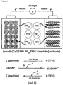
- the compound according to the present invention accepts electrons from the external circuit and is reduced to e.g. a CuDEPP 2- species.
- a CuDEPP 2- species e.g. a CuDEPP 2- species.
- TFSI - anions from the electrolyte can be intercalated into the graphite cathode.
- PP 14 + cations from the electrolyte compensate the negative charge of CuDEPP 2- anions.
- the TFSI - anions are deintercalated from the graphite cathode, while CuDEPP 2- anions of the anode release electrons to the external circuit and are oxidized to the neutral state.
- a battery cell according to this embodiment possesses a good specific energy density.
- a battery cell according to this embodiment possesses a specific energy density of at least 40 Wh/kg, preferably of at least 60 Wh/kg, at least 80 Wh/kg, at least 100 Wh/kg, and most preferably of at least 120 Wh/kg.
- a battery cell according to this embodiment has an excellent specific power density.
- the specific power density of such a battery cell is at least 1100 W/kg, preferably at least 2000 W/kg, at least 3000 W/kg, at least 6000 W/kg, and most preferably at least 14000 W/kg.
- a battery cell comprising the electrode according to the present invention as an anode can advantageously deliver a high specific power of e.g. 14 kW kg -1 at a high current density of 10 A g -1 (discharge capacity of 32 mAh g -1 within 12 seconds). Such values have only been possible with electrochemical capacitors so far.
- the bipolar redox reactivity of the compound according to the present application enables the construction of an all-organic rechargeable battery.
- the battery cell comprises two electrodes according to the present invention, wherein one of the two electrodes is operated as a cathode and the other electrode is operated as an anode.
- the working mechanism of such an all-organic battery is schematically illustrated in Figure 4 in the form of a CuDEPP / LiPF 6 / CuDEPP cell.
- the CuDEPP anode accepts electrons from an external circuit forming a CuDEPP 2- species with Li + insertion from the electrolyte for the charge balance, while the CuDEPP cathode donates its electrons to an external circuit with PF 6 - insertion for the charge balance.
- the CuDEPP 2- dianions in the anode release electrons and are oxidized to the neutral state of CuDEPP, while the CuDEPP 2+ dications in the cathode uptake electrons and are reduced to the neutral state of CuDEPP.
- the Li + and PF 6 - ions from the anode and cathode return to the electrolyte.
- the electrolyte used for the battery cell of this embodiment is preferably LiPF 6 .
- a battery cell according to this embodiment possesses an excellent specific energy density.
- a battery cell according to this embodiment possesses a specific energy density of at least 48 Wh/kg, preferably of at least 60 Wh/kg, at least 80 Wh/kg, at least 120 Wh/kg, and most preferably of at least 150 Wh/kg.
- a battery cell according to this embodiment has a superb specific power density.
- the specific power density of such a battery cell is at least 150 W/kg, preferably at least 160 W/kg, at least 200 W/kg, at least 240 W/kg, and most preferably at least 250 W/kg.
- the compound according to the present invention has been identified as a novel bipolar redox material enabling diverse rechargeable battery configurations.
- Different battery systems can be realized by employing said compound as an electrode material.
- a Li / LiPF 6 / CuDEPP battery can deliver an initial discharge capacity of 210 mAh g -1 .
- a capacity retention of approximately 85 % and 60 % at a high current density of 4 A g -1 can be maintained within 2000 and 8000 cycles, respectively, which demonstrates an excellent cyclability with a high average potential of 3.0 V (vs Li).
- a stable reversible discharge capacity of e.g. 115 mAh g -1 can be achieved at a current of 10 A g -1 within 42 seconds, offering an outstanding specific power of 29 kW kg -1 and a high specific energy density of 345 Wh kg -1 .
- the compound of the present invention can also be applied in a lithium free battery as e.g. a CuDEPP / PP 14 TFSI / graphite battery, in which the CuDEPP serves as an anode-active material.
- a discharge capacity of e.g. 94 mAh g -1 can be obtained at a current density of 1 A g -1 .
- superb cycling and an excellent rate performance can be achieved.
- the bipolar redox reactivity of the compound of the present invention in the form of e.g. CuDEPP and enabling a four electron transfer, was further confirmed.
- the rapid redox conversion of the electrode of the present invention can involve four electrons per molecule for the electrochemical reaction, which can be ascribed to the facile redox reactivity of the porphyrin complexes.
- the stabilization of the redox species by the highly ⁇ -conjugated structure plays an important role in sustaining excellent battery performance.
- the diversity of the compound of the present invention as an electrode-active material highlights a new approach for the molecular design of bipolar redox organic electrode.
- 5,15-Bis(trimethylsilanylethynyl)-10,20-diphenyl-21H,23H-porphyrin was purchased from Frontier Scientific Inc.
- the LiPF 6 electrolyte was purchased from BASF.
- Ionic liquid PP 14 TFSI was received from IOLITEC.
- [5,10,15,20-tetraphenylporphinato]copper(II) (CuTPP) and graphite material were purchased from Sigma-Aldrich. The graphite was dried at 473 K for 12 h under vacuum.
- the electrolyte containing 1 M lithium hexafluorophosphate (LiPF 6 ) in ethylene carbonate (EC) : dimethyl carbonate (DMC) : propylene carbonate (PC) (1 : 3 : 1 by volume) was used for testing the electrochemical performance of Li/LiPF 6 /CuDEPP and CuDEPP/LiPF 6 /CuDEPP cells.
- the ionic liquid of 1-butyl-1-methylpiperidinium bis(trifluoromethylsulfonyl)imide (PP 14 TFSI, 99 %, IoLiTech) dried at 358 K for 72 h under vacuum was used as an electrolyte for the CuDEPP/PP 14 TFSI/graphite cell. All other chemicals were purchased from Sigma Aldrich.
- THF was distilled from sodium prior to use.
- Et 3 N was distilled over CaH 2 and stored under argon.
- PP 14 TFSI was dried at 80°C in vacuum for 24 hours.
- IR spectra were measured in KBr pellets on MAGNA FTIR 750, Nicolet. Scanning electron microscope (SEM) measurements were carried out using a ZEISS LEO 1530 instrument. Powder X-ray diffraction (XRD) patterns were recorded in transmission geometry using a STOE STADI-P diffractometer (operated at 40 kV, 40 mA). The thermogravimetric analysis (TGA) was conducted by a SETARAM SENSYS Evo thermal analyzer under air flow (20 mL min -1 ) with a heating rate of 5°C min -1 .
- Electrochemical measurements were performed using a 2032 coin-type cell. A Whatman glass fiber sheet was used as separator. The assembly of the cells was conducted in an argon filled MBRAUN glove box with water and oxygen concentrations below 0.1 ppm. The cells were placed in an incubator to maintain a constant temperature of 25 ⁇ 0.1°C. Galvanostatic charge-discharge measurements were performed using an Arbin battery tester. Cyclic voltammetry (CV) measurements were conducted using a Biologic VMP-3 potentiostat. For galvanostatic charge-discharge measurements, the charge-discharge voltage range of cell 1 (Example 3) was between 4.5 V and 1.8 V. The open circuit voltage of the cell 1 was 3.0 ⁇ 0.1 V and it was firstly charged to 4.5 V.
- the charge-discharge voltage range of cell 2 (Example 6) was between 4.0 V and 0.0 V.
- the open circuit voltage of the cell 2 was 0 ⁇ 0.1 V and it was firstly charged to 4.0 V.
- the charge-discharge voltage range of cell 3 (Example 7) were between 2.8 V and 0.0 V or between 2.6 V and (-1.8) V.
- the open circuit voltage of the cell 3 was 0 ⁇ 0.1 V.
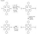
- CuDEPP was synthesized as depicted in Figure 6 . Reactions requiring an inert gas atmosphere were conducted under argon, and the glassware was oven-dried (140°C).
- Example 2 Formation of a CuDEPP electrode comprising CuDEPP, a binder and an electrically conductive additive
- a slurry was prepared by mixing CuDEPP (50 wt%) with carbon black (40 wt%) and a polyvinylidene fluoride binder (PVDF, 10 wt%) in N-methylpyrrolidone (NMP) as solvent.
- PVDF polyvinylidene fluoride binder
- NMP N-methylpyrrolidone
- Example 3 Battery system comprising a CuDEPP cathode
- a battery system i.e. Li / LiPF 6 / CuDEPP
- Li / LiPF 6 / CuDEPP Li / LiPF 6 / CuDEPP
- EC:PC:DMC 1:1:3 by volume ratio
- EC ethylene carbonate
- DMC dimethyl carbonate
- PC propylene carbonate
- the strong oxidative peak shown in Figure 7 at 4.2 V can be assigned to the oxidation of CuDEPP to [CuDEPP] 2+ and a possible polymerization of the ethynyl units.
- the cathodic peak at 2.34 V corresponds to the reductions at the porphyrin core e.g. CuDEPP 2+ to CuDEPP 2- .
- the lowest irreversible reductive signals at about 1.27 and 0.78 V are probably associated with the reduction of the center Cu(II) to Cu(I) and/or other side reactions.
- the reversible redox pair at 2.24 and 2.90 V relates to the redox reaction of the CuDEPP.
- the weak intensity of the redox peaks may be caused by the faster electron transfer process among the CuDEPP species, which is also reflected in the sloping discharge/charge profiles described herein below.
- the voltage range of 4.5 - 1.8 V was accordingly applied to examine the electrochemical performance of the CuDEPP as a cathode in the galvanostatic charge/discharge tests.
- the first charge capacity was approximately 400 mAh g -1 at a current density of 200 mA g -1 ( Fig. 9 ), which is higher than the value estimated by two-electron oxidation from the CuDEPP to CuDEPP 2+ (The specific capacity was calculated based on the mass of CuDEPP, theoretical capacity of the CuDEPP electrode is 47 mAh g -1 for one-electron transfer).
- the first discharge capacity was about 210 mAh g -1 and gradually decreased to 182 mAh g -1 in the third cycle which is close to the theoretical value of 187 mAh g -1 based on the four-electron reaction from the dication to the dianionic species of the molecule (CuDEPP 2+ ⁇ CuDEPP 2- , vice versa for the recharge process).
- a highly reversible discharge and charge profile was observed upon cycling after the first charge, delivering an average output voltage of about 3 V. No well-defined voltage plateaus were observed in charge/discharge profiles of the Li / LiPF 6 / CuDEPP cell, implying a fast electron transfer process through a solid solution reaction mechanism rather than a two-phase transition mechanism.
- the subtle discharge behaviors were indicated in a dQ/dV plot of initial cycles as shown in Fig. 10 , in which four potential peaks at 3.94, 3.69, 2.88 and 2.2 V were revealed.
- the cycling and rate performance of the cell of Example 3 was further evaluated. As shown in Fig. 11 , the cell maintained a discharge capacity of about 185 mAh g -1 with a coulombic efficiency of 84 % after the initial 20 cycles at a current density of 200 mA g -1 . Subsequently, the cell was cycled by applying increased current rates. The stable discharge capacities of 163, 143, 132, 125 mAh g -1 were respectively retained at the current of from 1, 2, 4 , 6 and 10 A g -1 within a period of about 100 cycles. Moreover, the discharge capacities of the CuDEPP electrode were mostly retrieved by stepwise tuning the current from 10 to 1 A g -1 .
- the selected discharge curves of the CuDEPP electrode at different current rates are shown in Fig. 12 , which presents slightly decreased potentials upon increasing the discharge rate.
- the CuDEPP electrode could still deliver a stable reversible discharge capacity of 115 mAh g -1 , which was obtained within 42 seconds with a coulombic efficiency of 99.5 %, demonstrating an excellent electrochemical performance.
- This value corresponds to a specific energy density of 345 Wh kg -1 and a specific power of 29.5 KW Kg -1 , which is competitive with some of supercapacitors.
- the outstanding cyclability at the extremely high current density of 10 A g -1 was represented in the characteristic charge/discharge profiles ( Fig. 13 ).
- the long-term cycling performance of a Li / LiPF 6 / CuDEPP cell comprising a cathode consisting of CuDEPP only at a high current density of 4 A g -1 was also investigated.
- the cell was initially cycled at a current density of 200 mA g -1 for 20 cycles to "activate" the CuDEPP cathode.
- the cell was cycled at a current of 4 A g -1 for 8100 cycles in total.
- a maximal capacity of 150 mAh g -1 was obtained in the 226 th cycle.
- the capacity retention was approximately 85 % for the first 2000 cycles and gradually decreased to 60 % after 8000 cycles with a high coulombic efficiency (close to 100 %).
- the selected charge and discharge profiles of the CuDEPP cathode are shown in Fig. 15 and 16 . Additional cyclic voltammograms were captured after cycling the Li / LiPF 6 / CuDEPP cell for 2000 cycles. As shown in Fig. 17 , a reversible pair of well-defined redox peaks at approximately 3 V was observed at a sweeping rate of 10 mV s -1 , which is consistent with the average discharge/charge potential of 3 V.
- Fig. 18 shows the high reversibility of the CV curve at a high scan rate of 100 mV s -1 , which demonstrates the excellent rate capability of the CuDEPP cathode.
- the electrochemical behavior of the Li / LiPF 6 / CuDEPP cell of Example 3 was also examined by starting with discharging based on the reaction CuDEPP + 2e ⁇ CuDEPP 2- .
- the first charge curve was similar to the cell 1 described above, the discharge voltage decreased steeply from the open circuit voltage (OCV) of 3.1 V to 1.5 V, resulting in a lower reversible capacity in the subsequent cycles at a current rate of 200 mA g -1 .
- Example 4 Analysis of the morphology and crystallinity of a CuDEPP electrode
- the morphology and crystallinity of the CuDEPP electrode material in the first cycles was analyzed by ex-situ SEM and XRD, respectively.
- pure CuDEPP was tested in a coin cell.
- the electrode was fabricated by directly pressing CuDEPP on the rough stainless steel current collector. The setup for the measurements is the same as described in Example 3.
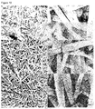
- Fig. 19a and b show that the initial CuDEPP has a rod-like crystalline morphology with a size around 4 ⁇ m in length, 200 - 400 nm in width.
- a lowered crystallinity of the CuDEPP was observed after charge/discharge as shown in Fig. 19c-f .
- the sharp peaks in the XRD patterns indicate the good crystallinity of the synthesized CuDEPP material, which changed to amorphous and/or nanosized crystalline in the charged and discharged state, respectively ( Fig. 20 ).
- Example 5 Electrochemical performance of carbon free CuDEPP electrode
- the CuDEPP material was directly pressed on a stainless steel and used as cathode.
- the battery performance was examined at a current density of 200 mA g -1 .
- An initial discharge capacity of 85 mAh g -1 was obtained for the pure CuDEPP electrode in a voltage range of 4.5 - 1.8 V.
- a discharge capacity of 80 mAh g -1 was maintained.
- Comparative Example 1 Battery system comprising a CuTPP electrode
- EC:PC:DMC 1:1:3 by volume ratio
- ethylene carbonate EC
- DMC dimethyl carbonate
- PC propylene carbonate
- the battery's performance was not satisfying, since the said cell only delivered a reversible capacity of 40 mAh g -1 at a current density of 100 mA g -1 . This can probably be associated with the high solubility of active material in the electrolyte or other inherent limitations of its electrochemical properties.
- Example 6 Battery system comprising a CuDEPP anode
- a lithium free recharge battery (cf. Figure 3 ) was formed by coupling the CuDEPP of Example 2 as an anode and graphite as an intercalation cathode in the pure ionic liquid electrolyte 1-butyl-1-methylpiperidinium bis(trifluoromethylsulfonyl)imide (PP 14 TFSI).
- the CV measurements were performed using the graphite as working electrode and the CuDEPP electrode of Example 2 as the counter electrode in pure PP 14 TFSI electrolyte in a potential range of 4.0 - 0.0 V at different scanning rates as shown in Figures 21 and 22 .
- a sharp couple of oxidation/reduction peaks were observed at 3.51/3.14 V, which are associated with the intercalation/de-intercalation of TFSI - into/from the graphite electrode.
- TFSI - anions into the graphite layers was verified by means of SEM, EDX and XRD measurements.
- the charged/discharged graphite samples were prepared by initially charging the CuDEPP / PP 14 TFSI / graphite cell of Example 6 at a current of 200 mA g -1 to a cut-off voltage of 4 V and the subsequent discharge to 0 V.
- the elemental maps shown in Figures 23 to 28 indicated that carbon (C), oxygen (O), fluorine (F), nitrogen (N) and sulfur (S) were uniformly distributed in the charged graphite electrode.
- the EDX also confirmed the presence of the TFSI - species in the graphite cathode (cf. Figure 29 ).
- the galvanostatic charge-discharge tests for the CuDEPP / PP 14 TFSI / graphite cell of Example 6 were carried out in a voltage range of 4.0 to 0.0 V at different current rates.
- the open circuit voltage (OCV) of the cell was close to 0 V (24 mV).
- a slopping curve is observed in the discharge profile at a current of 1 A g -1 delivering a capacity of 94 mAh g -1 (cf. Figure 31 ), which is close to the theoretical value of the CuDEPP anode based on a two electron transfer (CuDEPP ⁇ CuDEPP 2- , 93.5 mAh g -1 ).
- Example 7 All-organic battery system comprising a CuDEPP anode and a CuDEPP cathode
- DMC dimethyl carbonate
- PC propylene carbonate
Landscapes
- Chemical & Material Sciences (AREA)
- Organic Chemistry (AREA)
- Chemical Kinetics & Catalysis (AREA)
- Electrochemistry (AREA)
- General Chemical & Material Sciences (AREA)
- Engineering & Computer Science (AREA)
- Manufacturing & Machinery (AREA)
- Battery Electrode And Active Subsutance (AREA)
- Secondary Cells (AREA)
Abstract
Description
- The present invention relates to a compound, which can be used as an electrode material, an electrode comprising said compound, and a battery cell comprising at least one of said electrode.
- Rechargeable lithium ion batteries (LIBs) have been successfully developed over the last two to three decades and widely used to power today's portable electronic devices. The aim at long-term success in electric vehicles and grid-scale renewable energy storage raises great challenges with respect to high energy densities, long cycle lives, good safety and low-costs of the batteries. It is recognized that conventional lithium ion battery systems are approaching their theoretical energy density limits and their lifetime and charging rate must be improved.
- Rechargeable batteries based on organic electrode materials are potential alternatives to conventional lithium-ion batteries due to their tunable properties, environmental friendliness, flexibility, good safety, sustainability and relative low cost. The organic molecules can be divided into n-type organic, p-type organic, and bipolar organic molecules, in which the neutral molecule can be either oxidized to the positively charged state or reduced to the negatively charged state.
- Different from conventional inorganic electrode materials in LIBs, the battery performance of organic electrodes greatly depends on their molecular structures, which can be desirably tailored by synthesis.
- Porphyrins have an aromatic 18 π conjugated system delocalized over 24 core atoms which satisfy Hückel's (4n+2) π-electron rule. Many porphyrins and metalloporphyrins exist naturally and have a wide range of application, e.g. in light harvesting, as a catalyst, or in solar cells. Porphyrins and their derivatives with highly conjugated π-systems are suitable for efficient electron transfer processes due to the minimal structural change of the molecules during the removal or uptake of an electron. 16 π-electron and 20 π-electron "antiaromatic" porphyrins are accessible by the oxidation or reduction of the 18 π-electron systems of aromatic porphyrins and in some cases can be successfully isolated and structurally determined.
- However, so far no organic electrode materials had been available which are able to provide batteries having high power, high energy densities as well as very good cyclic stabilities.
- Thus, the technical problem underlying the present invention is to provide a compound, which can be used as an "organic" electrode material, as well as a corresponding battery cell having a high power density as well as a superior energy density.
- The solution to the above technical problem is achieved by the embodiments characterized in the claims.
- In particular, the present invention relates to a compound of the general Formula (1)

- According to the present invention, M is selected from the group consisting of a transition metal ion, preferably selected from the group consisting of Ti, Cr, Mn, Fe, Co, Ni, Cu, Zn, Zr, Mo, Ru, Rh, Pd, Ag, W, Re, Os, Ir, Pt, and Au, an alkaline earth metal ion, preferably selected from the group consisting of Mg and Ca, a p-block element ion, preferably selected from the group consisting of B, Al, Ga, In, Si, Ge, Sn, Pb, As, Sb, Bi, Se, and Te, and a lanthanide ion, preferably selected from the group consisting of La, Ce, Sm, and Eu. Preferably, the ions are in a stable oxidation state (for example Cu(II)). The electron transfer processes of porphyrin complexes depend on the nature of the central metal ions M as well as the axial coordination that may alter the structural, spectroscopic and the redox properties. In a preferred embodiment of the present application, M is Cu(II). Cu(II) porphyrin complexes possess low reactivity at the metal ion and are therefore particularly suitable for the utilization as electrode-active materials in rechargeable batteries, since a redox reaction at the central metal may lead to undesired structural changes in the initial porphyrins and may thus negatively influence the reversibility of the battery.
- The commercial available porphyrin complex [5,10,15,20-tetraphenylporphinato]copper(II) (CuTPP) was initially probed as a cathode in a battery system further comprising a Li metal anode and 1 M LiPF6 in a solvent mixture of ethylene carbonate (EC), dimethyl carbonate (DMC), and propylene carbonate (PC) as the electrolyte. However, the battery's performance was not satisfying, probably due to the high solubility of active material in the electrolyte or other inherent limitations of its electrochemical properties.
- According to the present invention, the introduction of at least one alkynyl, preferably ethynyl, moiety in porphyrins surprisingly results in compounds, which show an excellent battery performance, with storage capacities comparable to those of state-of-the art systems but with charge and discharge rates being comparable to those of capacitors and superior to those of lithium ion batteries, as will be described herein below. Thus, according to the general Formula (1) of the present invention, at least one or two of R1 to R4 is/are an alkynyl group. Preferably, at least one or two of R1 to R4 is/are an ethynyl group.
- Herein the term "halogen" refers particularly to fluorine atoms, chlorine atoms, bromine atoms, and iodine atoms. The term "alkyl group" refers particularly to a branched or linear alkyl group having 1 to 20, preferably 1 to 12, more preferably 1 to 6, and most preferably 1 to 4 carbon atoms, which can be substituted or unsubstituted. The term "alkenyl group" refers particularly to a branched or linear alkenyl group having 2 to 20, preferably 2 to 12, more preferably 2 to 6, and most preferably 2 to 4 carbon atoms, which can be substituted or unsubstituted. The term "alkynyl group" refers particularly to a branched or linear alkynyl group having 2 to 20, preferably 2 to 12, more preferably 2 to 6, more preferably 2 to 4 carbon atoms, and most preferably 2 carbon atoms (i.e. an ethynyl group), which can be substituted or unsubstituted. The term "aryl group" refers particularly to an aryl group consisting of 1 to 6, preferably 1 to 4, more preferably 1 to 3 rings, and most preferably 1 ring, which can be substituted or unsubstituted. Examples of aryl groups represent phenyl groups, anthracenyl or naphthyl groups. The term "heteroaryl group" refers particularly to a heteroaryl group consisting of 1 to 6, preferably 1 to 4, more preferably 1 to 3 rings, which can be substituted or unsubstituted. Examples of heteroaryl groups represent pyridyl groups, pyrimidinyl groups, thienyl groups, furyl groups or pyrrolyl groups.
- According to the present invention, the ethynyl groups, the phenyl groups, the alkyl groups, the alkenyl groups, the alkynyl groups, the aryl groups and the heteroaryl groups may be substituted or unsubstituted. The potential substituents are not specifically limited. Accordingly, instead of hydrogen atoms any substituent known in the prior art can be bonded to the further positions of the corresponding groups. For example, the potential substituents may be selected from the group consisting of an alkyl group, an alkenyl group, an alkynyl group, an aryl group, a heteroaryl group, a halogen atom, -NZ1Z2, -NO2, -CN, -OZ3, -C(O)Z4, -C(O)NZ5Z6, and -COOZ7, wherein Z1 to Z7 are each independently selected from a hydrogen atom, an alkyl group, an alkenyl group, an alkynyl group, an aryl group, a heteroaryl group, and a halogen atom. Most preferably, the ethynyl groups, the phenyl groups, the alkyl groups, the alkenyl groups, the alkynyl groups, the aryl groups and the heteroaryl groups are unsubstituted.
- In a preferred embodiment of the compound according to the present invention, R1 and R3 are each an alkynyl group. More preferably, R1 and R3 are each an ethynyl group.
- Preferably, R2 and R4 are each an aryl group. More preferably, R2 and R4 are each a phenyl group.
- In a preferred embodiment of the compound according to the present invention, the compound of Formula (1) is [5,15-bis(ethynyl)-10,20-diphenylporphinato]copper(II) (CuDEPP, cf. Formula (2)), meaning that R1 and R3 are each an unsubstituted ethynyl group, R2 and R4 are each an unsubstituted phenyl group, and X1 to X8 are each a hydrogen atom.

- Moreover, CuDEPP has a relatively low solubility in the applied electrolytes when compared to CuTPP, which is beneficial for battery applications. On the other hand, the low solubility in common organic solvents such as dichloromethane (CH2Cl2) and acetonitrile (CH3CN) prohibits the electrochemical analysis of CuDEPP by cyclic voltammetry (CV) in a solution condition. Based on the reported redox chemistry of the analogue compound CuTPP, a reversible two-electron oxidation and a two-electron reduction can be proposed for CuDEPP bearing 18 π-electrons, forming a dicationic species (CuDEPP2+, 16 π-electrons) and a dianionic species (CuDEPP2-, 20 π-electrons), respectively (cf.
Figure 1 ). - In a further aspect, the present invention relates to the use of the compound according to the present invention as an electrode material in a battery, preferably secondary battery. The above statements and definitions analogously apply to this aspect of the present invention. By using the compound according to the present invention as an electrode material, it is advantageously possible to produce electrodes with superior electrochemical properties, which can be used both as a cathode and an anode. Thus, even all-organic batteries can be provided by using the compound according to the present invention as an electrode material.
- In a further aspect, the present invention relates to an electrode comprising the compound according to the present invention. The above statements and definitions analogously apply to this aspect of the present invention.
- The content of the compound according to the present invention in the electrode is not specifically limited. Accordingly, the electrode may consist exclusively of the compound of the present invention or may also comprise or consist of further electrode materials. Thus, in a preferred embodiment of the present invention, the content (by weight) of the compound according to the present invention is from 20% to 100%, based on the total weight of the electrode. More preferably, the content of the compound according to the present invention is from 20% to 95%, even more preferably from 30% to 80%, from 40% to 75%, from 45% to 70%, and most preferably from 50% to 65%, based on the total weight of the electrode.
- The potential further electrode materials apart from the compound of the present invention are not specifically limited. Therefore, all kinds of electrode materials known in the art may be used. For example, the electrode may further comprise or consist of binders and/or electrically conductive additives, as e.g. carbon black, carbon nanotubes, carbon nanofibers, graphite, graphene, and graphene oxide. In a preferred embodiment, the electrode of the present invention comprises the compound according to the present invention, a binder, and carbon black. More preferably, the electrode according to the present invention consists of the compound according to the present invention, a binder, and carbon black.
- In a preferred embodiment of the present invention, the content (by weight) of the binder in the electrode according to the present invention is from 0% to 40%, based on the total weight of the electrode. More preferably, the content of the binder is from 0% to 30%, even more preferably from 2% to 25%, from 3% to 20%, from 4% to 15%, and most preferably from 5% to 12%, based on the total weight of the electrode.
- The possible binders are not specially limited. Thus, any binder known in the art can potentially be present in the electrode according to the present invention. For example, the binder, when present, can be selected from the group consisting of polyvinylidene fluoride (PVDF), polyvinylidene fluoride-co-hexafluoropropene (PVDF-HFP), sodium carboxymethyl cellulose (CMC), polyvinylpyrrolidone (PVP), poly(ethyleneoxide) (PEO), polytetrafluorethylene (PTFE), and poly(acrylic acid) (PAA). Preferably, the binder is selected from the group consisting of polyvinylidene fluoride (PVDF), polyvinylidene fluoride-co-hexafluoropropene (PVDF-HFP), sodium carboxymethyl cellulose (CMC), and polytetrafluorethylene (PTFE). Most preferably, the binder is polyvinylidene fluoride (PVDF). Polyvinylidene fluoride (PVDF) provides advantages in electrode processing, for example in terms of versatility, environmental impact and safety.
- In a preferred embodiment of the present invention, the content (by weight) of electrically conductive additives in the electrode according to the present invention is from 0% to 80%, based on the total weight of the electrode. More preferably, the content of electrically conductive additives is from 10% to 70%, even more preferably from 20% to 65%, from 25% to 60%, from 30% to 50%, and most preferably from 35% to 45%, based on the total weight of the electrode. A content of electrically conductive additives falling out of the above-identified range may lead to a lower reversible capacity.
- In a further aspect, the present invention relates to a battery cell comprising at least one electrode according to the present invention. The above statements and definitions analogously apply to this aspect of the present invention.
- The electrolyte used in the battery cell is not specifically limited. Thus, any electrolyte known in the art can be used in the battery cell according to the present invention. For example, the electrolyte can be selected from the group consisting of LiPF6, 1-butyl-1-methylpiperidinium bis(trifluoromethylsulfonyl)imide (PP14TFSI), lithium perchlorate (LiClO4), lithium trifluoromethane sulfonate (LiCF3SO3), lithium bis(trifluoromethanesulfonyl)imide (LiTFSI), lithium bis(perfluoroethylsulfonyl)imide (LiN(CF3CF2SO2)2), lithium tetrafluoroborate (LiBF4), lithium bis(oxalato)borate (LiB(C2O4)2), sodium hexafluorophosphate (NaPF6), sodium perchlorate (NaClO4), N-methyl-N-propylpyrrolidinium bis(trifluoromethanesulfonyl)imide (PP13TFSI) and ionic liquids, which consist of organic cations such as 1-alkyl-3-methylimidazolium, 1-alkylpyridinium, N-methyl-N-alkylpyrrolidinium, ammonium, and phosphonium, and anions such as halides, tetrafluoroborate, hexafluorophosphate, bistriflimide, triflate, or tosylate. Preferably, the electrolyte is selected from the group consisting of LiPF6, PP14TFSI, LiClO4, LiTFSI, LiN(CF3CF2SO2)2, LiB(C2O4)2, NaPF6, NaClO4, and PP13TFSI. Most preferably, the electrolyte is selected from the group consisting of LiPF6 and PP14TFSI.
- The electrolyte may be dissolved in a solvent or a solvent mixture. Solvents for electrolyte solutions are known in the art. For example, the electrolyte can be dissolved in one or more solvents selected from the group consisting of ethylene carbonate (EC), dimethyl carbonate (DMC), propylene carbonate (PC), 1,3-dioxolane (DOL), 1,2-dimethoxyethane (DME), γ-butyrolactone, acetonitrile, and glymes. Preferably, the electrolyte is dissolved in one or more solvents selected from the group consisting of ethylene carbonate (EC), dimethyl carbonate (DMC), propylene carbonate (PC), and γ-butyrolactone. Most preferably, the electrolyte is dissolved in a solvent mixture consisting of ethylene carbonate (EC), dimethyl carbonate (DMC) and propylene carbonate (PC).
- The mixture ratio of the one or more solvents for dissolving the electrolyte, when present, is not specifically limited. For example, when ethylene carbonate (EC), dimethyl carbonate (DMC) and propylene carbonate (PC) are used as a solvent mixture, 10 to 80 parts by volume of ethylene carbonate (EC), preferably 20 to 60 parts by volume, and most preferably 30 to 50 parts by volume, may be mixed with 10 to 80 parts by volume of dimethyl carbonate (DMC), preferably 20 to 60 parts by volume, and most preferably 30 to 50 parts by volume, as well as 10 to 80 parts by volume of propylene carbonate (PC), preferably 10 to 60 parts by volume, and most preferably 15 to 40 parts by volume, based on a total volume of the solvent mixture of 100 parts.
- When dissolved, the concentration of the electrolyte in the solvent or the solvent mixture is not specifically limited. Preferably, the concentration of the electrolyte in the solvent or the solvent mixture is from 0.01 to 5 M, more preferably from 0.1 to 4 M, from 0.2 to 3 M, from 0.4 to 2 M, from 0.6 to 1.5 M, and most preferably from 0.8 to 1.2 M.
- As already stated above, an electrode according to the present invention which comprises the compound according to the present invention can advantageously be used as a cathode and/or an anode in a battery cell.
- Thus, according to one embodiment of the battery cell according to the present invention, the battery cell comprises one electrode according to the present invention, wherein said electrode is operated/functions as a cathode. One example of a corresponding battery cell is depicted in
Figure 2 . The anode of the battery cell according to this embodiment is not specifically limited. Thus any anode known in the prior art can be used. For example, the anode can be selected from the group consisting of a Li electrode, as for example a Li foil, a Li4Ti5O12 electrode, a Li4.4Sn electrode, a Li4.4Si electrode, a sodium (Na) electrode, a potassium (K) electrode, a magnesium (Mg) electrode, and a calcium (Ca) electrode. Preferably, the anode is a lithium electrode. Most preferably, the anode is a Li foil. The electrolyte used for the battery cell of this embodiment is preferably LiPF6. This electrolyte has a high chemical stability and good electrochemical properties. Advantageously, a battery cell according to this embodiment possesses an excellent specific energy density. For example, a battery cell according to this embodiment possesses a specific energy density of at least 345 Wh/kg, preferably of at least 375 Wh/kg, at least 396 Wh/kg, at least 429 Wh/kg, and most preferably of at least 555 Wh/kg. Moreover, a battery cell according to this embodiment has an excellent specific power density. For example, the specific power density of such a battery cell is at least 590 W/kg, preferably at least 2900 W/kg, at least 5900 W/kg, at least 18000 W/kg, and most preferably at least 29500 W/kg. - Furthermore, a battery cell comprising the electrode according to the present invention as a cathode advantageously possesses an excellent long-term cycle life and an outstanding rate performance. Remarkably, even at high current densities of e.g. 10 A g-1, the electrode according to the present invention can still deliver a stable reversible discharge capacity (e.g. 115 mAh g-1 with an average output voltage of 3 V (vs Li/Li+), obtained within 42 seconds with a coulombic efficiency of 99.5 %), which demonstrates its excellent electrochemical performance. Moreover, a capacity retention of 85 % after 2000 cycles and of 60 % after 8000 cycles can for example be obtained at a current rate of 4 A g-1. Preferably, a first charging process is conducted when using a battery system which comprises the electrode of the present invention as a cathode, since said first charging process results in a superior battery performance.
- According to another embodiment of the battery according to the present invention, the battery cell comprises one electrode according to the present invention, wherein said electrode is operated/functions as an anode. One example of a corresponding battery cell is depicted in
Figure 3 . - The cathode of the battery cell according to this embodiment is not specifically limited. Thus any cathode known in the prior art can be used. Preferably, cathode materials with layered structures are used. Accordingly, the cathode is preferably selected from the group consisting of a graphite electrode, a graphene electrode, a graphene oxide electrode, and a MoS2 electrode. More preferably, the cathode is selected from the group consisting of a graphite electrode, a graphene electrode, and a graphene oxide electrode. Most preferably, the cathode is a graphite electrode.
- The electrolyte used for the battery cell of this embodiment is preferably 1-butyl-1-methylpiperidinium bis(trifluoromethylsulfonyl)imide (PP14TFSI). PP14TFSI has a high dielectric constant and ionic conductivity and it is safe for battery application due to its high chemical and thermal stability as well as non-toxic properties.
- Upon charging, the compound according to the present invention, as e.g. CuDEPP, accepts electrons from the external circuit and is reduced to e.g. a CuDEPP2- species. In parallel, when e.g. PP14TFSI is used as the electrolyte and e.g. graphite is used as the cathode, TFSI- anions from the electrolyte can be intercalated into the graphite cathode. In this case, PP14 + cations from the electrolyte compensate the negative charge of CuDEPP2- anions. During reverse discharge, the TFSI- anions are deintercalated from the graphite cathode, while CuDEPP2- anions of the anode release electrons to the external circuit and are oxidized to the neutral state.
- Advantageously, a battery cell according to this embodiment possesses a good specific energy density. For example, a battery cell according to this embodiment possesses a specific energy density of at least 40 Wh/kg, preferably of at least 60 Wh/kg, at least 80 Wh/kg, at least 100 Wh/kg, and most preferably of at least 120 Wh/kg.
- Moreover, a battery cell according to this embodiment has an excellent specific power density. For example, the specific power density of such a battery cell is at least 1100 W/kg, preferably at least 2000 W/kg, at least 3000 W/kg, at least 6000 W/kg, and most preferably at least 14000 W/kg.
- A battery cell comprising the electrode according to the present invention as an anode can advantageously deliver a high specific power of e.g. 14 kW kg-1 at a high current density of 10 A g-1 (discharge capacity of 32 mAh g-1 within 12 seconds). Such values have only been possible with electrochemical capacitors so far.
- Apart from the two above-described embodiments, the bipolar redox reactivity of the compound according to the present application enables the construction of an all-organic rechargeable battery. Thus, according to another embodiment of the present invention, the battery cell comprises two electrodes according to the present invention, wherein one of the two electrodes is operated as a cathode and the other electrode is operated as an anode.
- The working mechanism of such an all-organic battery is schematically illustrated in
Figure 4 in the form of a CuDEPP / LiPF6/ CuDEPP cell. During charging, the CuDEPP anode accepts electrons from an external circuit forming a CuDEPP2- species with Li+ insertion from the electrolyte for the charge balance, while the CuDEPP cathode donates its electrons to an external circuit with PF6 - insertion for the charge balance. On reverse discharge, the CuDEPP2- dianions in the anode release electrons and are oxidized to the neutral state of CuDEPP, while the CuDEPP2+ dications in the cathode uptake electrons and are reduced to the neutral state of CuDEPP. The Li+ and PF6 - ions from the anode and cathode return to the electrolyte. - The electrolyte used for the battery cell of this embodiment is preferably LiPF6.
- Advantageously, a battery cell according to this embodiment possesses an excellent specific energy density. For example, a battery cell according to this embodiment possesses a specific energy density of at least 48 Wh/kg, preferably of at least 60 Wh/kg, at least 80 Wh/kg, at least 120 Wh/kg, and most preferably of at least 150 Wh/kg.
- Moreover, a battery cell according to this embodiment has a superb specific power density. For example, the specific power density of such a battery cell is at least 150 W/kg, preferably at least 160 W/kg, at least 200 W/kg, at least 240 W/kg, and most preferably at least 250 W/kg.
- The compound according to the present invention, as e.g. the aromatic porphyrin complex CuDEPP, has been identified as a novel bipolar redox material enabling diverse rechargeable battery configurations. Different battery systems can be realized by employing said compound as an electrode material. For example, a Li / LiPF6 / CuDEPP battery can deliver an initial discharge capacity of 210 mAh g-1. With such a battery a capacity retention of approximately 85 % and 60 % at a high current density of 4 A g-1 can be maintained within 2000 and 8000 cycles, respectively, which demonstrates an excellent cyclability with a high average potential of 3.0 V (vs Li). Remarkably, a stable reversible discharge capacity of e.g. 115 mAh g-1 can be achieved at a current of 10 A g-1 within 42 seconds, offering an outstanding specific power of 29 kW kg-1 and a high specific energy density of 345 Wh kg-1.
- The compound of the present invention can also be applied in a lithium free battery as e.g. a CuDEPP / PP14TFSI / graphite battery, in which the CuDEPP serves as an anode-active material. In this case, a discharge capacity of e.g. 94 mAh g-1 can be obtained at a current density of 1 A g-1. Moreover, superb cycling and an excellent rate performance can be achieved.
- In an all-organic symmetric configuration, the bipolar redox reactivity of the compound of the present invention, in the form of e.g. CuDEPP and enabling a four electron transfer, was further confirmed.
- In contrast to the slow lithium insertion process in conventional Li-ion batteries, the rapid redox conversion of the electrode of the present invention can involve four electrons per molecule for the electrochemical reaction, which can be ascribed to the facile redox reactivity of the porphyrin complexes. The stabilization of the redox species by the highly π-conjugated structure plays an important role in sustaining excellent battery performance. The diversity of the compound of the present invention as an electrode-active material highlights a new approach for the molecular design of bipolar redox organic electrode.
- In particular, the introduction of at least one alkynyl moiety, preferably ethynyl moiety, in porphyrins surprisingly resulted in compounds, which show an excellent battery performance, with storage capacities comparable to those of state-of-the art systems but with charge and discharge rates being comparable to those of capacitors and superior to those of lithium ion batteries (cf.
Figure 5 ). These findings can be applied to other organic compounds for electrochemical energy storage which contain alkynyl groups, and preferably ethynyl groups, as substituents that can stabilize the electrode in a formation step, leading to an electrically conductive network of less soluble electrode material. - The figures show:
-
Figure 1 : Schematics of the electron transformations: oxidation and reduction transformations among the 16, 18, 20 π-electrons of the porphyrin core. The bold line denotes each π-conjugation circuit (R1 = ethynyl, R2 = phenyl (i.e. CuDEPP)). -
Figure 2 : Cell system wherein the electrode according to the present invention is used as a cathode, and the corresponding schemes of the electron transformations between the cathode and the anode in the charge and discharge process. -
Figure 3 : Cell system wherein the electrode according to the present invention is used as an anode, and the corresponding schemes of the electron transformations between the cathode and the anode in the charge and discharge process. -
Figure 4 : Cell system wherein the electrode according to the present invention is used as a cathode as well as an anode, and the corresponding schemes of the electron transformations between the cathode and the anode in the charge and discharge process. -
Figure 5 : Ragone plots of the energy density and power density for various energy storage systems. The battery cells indicated by circles on the top right of the plot (i.e. "Cell 1") contain CuDEPP as cathode, lithium foil as anode, and LiPF6 in EC/DMC/PC solvent as the electrolyte. Four electrons can be transferred during the charge and discharge for these battery cells (i.e. between CuDEPP2+ and CuDEPP2-). The battery cells indicated by squares (i.e. "Cell 2") are lithium-free and contain graphite as cathode, CuDEPP as anode, and PP14TFSI as the electrolyte. Theoretically, two electrons can be transferred during the charge and discharge of these cells (i.e. between CuDEPP and CuDEPP2-). -
Figure 6 : Synthesis of CuDEPP starting from 5,15-dibromo-10,20-diphenyl-21H,23H-porphyrin. -
Figures 7 and 8 : Cyclic voltammogramm (CV) investigation of a Li / LiPF6 / CuDEPP cell. The CV curve of the Li / LiPF6 / CuDEPP cell in the first cycle in a voltage range of 4.5 - 0.05 V (Figure 7 ) and CV curves of initial five cycles in a voltage range of 4.5 - 1.8 V (Figure 8 ). The scan rate was 0.1 mV s-1. -
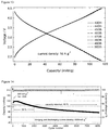
Figures 9 to 13 : Electrochemical performance of a CuDEPP cathode in a voltage range of 4.5 - 1.8 V: initial charge and discharge curves (Figure 9 ); dQ/dV plot of the discharge curve inFigure 9 (Figure 10 ); charge and discharge performance at different current rates (Figure 11 ); discharge curves at different current rates (Figure 12 ); and the selected charge/discharge profiles at a high current density of 10 A g-1 (Figure 13 ). -
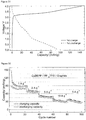
Figures 14 to 18 : Long-term cycling of a Li / LiPF6 / CuDEPP cell: cycling performance (Figure 14 ); selected charge and discharge curves at a current of 4 A g-1 (Figures 15 and 16 ); CV curves of the Li / LiPF6 / CuDEPP cell after 2000 cycles in a battery test at a sweeping rate of 10 mV s-1 (Figure 17 ) and 100 mV s-1 (Figure 18 ), respectively. - Figure 19: Morphology and crystallinity of a CuDEPP cathode material at different electrochemical states: SEM images of the as-prepared material (
Figure 19 , a and b), the charged to 4.5 V material (Figure 19, c and d ), and the discharged to 1.8 V material (Figure 19, e and f) . White and black scale bars represent 2 µm and 200 nm, respectively. -
Figure 20 : Morphology and crystallinity of a CuDEPP cathode material at different electrochemical states: the XRD patterns in the as-prepared scale, the charged to 4.5 V scale, and the discharged to 1.8 V scale of the CuDEPP electrode. -
Figures 21 and 22 : CV investigation of a CuDEPP / PP14TFSI / graphite cell: initial CV curves of the CuDEPP / PP14TFSI / graphite cell at a scanning rate of 5 mV s-1 (Figure 21 ) and20 mV s-1 (Figure 22 ), with a sweeping voltage range of 4.0 - 0.0 V. -
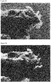
Figures 23 to 30 : The characterizations of the graphite electrode of a CuDEPP / PP14TFSI / graphite cell at different electrochemical states: SEM images of the charged graphite cathode (Figure 23 ); the corresponding element maps denoted as carbon, oxygen, fluorine, nitrogen and sulfur, respectively (Figures 24 to 28 ); the EDX sum spectrum of the charged graphite (Figure 29 ); and the XRD patterns of the graphite cathode in the as-prepared, the charged and the discharged state (Figure 30 ). -
Figures 31 and 32 : Rate performance of the CuDEPP / PP14TFSI / graphite cell: the first charge/discharge profiles at a current density of 1 A g-1 (Figure 31 ) and the rate performances in a voltage range of 4.0 - 0.0 V (Figure 32 ). -
Figures 33 and 34 : The cycling performance of the CuDEPP / PP14TFSI / graphite cell in the voltage range of 4.0 - 0.0 V: cycling performance at a current density of 5 A g-1 (Figure 33 ) and selected charge/discharge curves at the 50th, 100th and 150th cycle (Figure 34 ). -
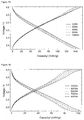
Figures 35 and 36 : Charge/discharge profiles of a symmetric CuDEPP / LiPF6 / CuDEPP cell: selected charge-discharge curves in the voltage range of 2.8 - 0.0 V at a current density of 200 mA g-1 (Figure 35 ; insert depicts the initial discharge curves) and selected charge-discharge curves 2.6 - (-1.8) V at a current density of 200 mA g-1 (Figure 36 ). - The present invention will be further illustrated in the following examples without being limited thereto.
- 5,15-Bis(trimethylsilanylethynyl)-10,20-diphenyl-21H,23H-porphyrin was purchased from Frontier Scientific Inc. The LiPF6 electrolyte was purchased from BASF. Ionic liquid PP14TFSI was received from IOLITEC. [5,10,15,20-tetraphenylporphinato]copper(II) (CuTPP) and graphite material were purchased from Sigma-Aldrich. The graphite was dried at 473 K for 12 h under vacuum. The electrolyte containing 1 M lithium hexafluorophosphate (LiPF6) in ethylene carbonate (EC) : dimethyl carbonate (DMC) : propylene carbonate (PC) (1 : 3 : 1 by volume) was used for testing the electrochemical performance of Li/LiPF6/CuDEPP and CuDEPP/LiPF6/CuDEPP cells. The ionic liquid of 1-butyl-1-methylpiperidinium bis(trifluoromethylsulfonyl)imide (PP14TFSI, 99 %, IoLiTech) dried at 358 K for 72 h under vacuum was used as an electrolyte for the CuDEPP/PP14TFSI/graphite cell. All other chemicals were purchased from Sigma Aldrich. THF was distilled from sodium prior to use. Et3N was distilled over CaH2 and stored under argon. PP14TFSI was dried at 80°C in vacuum for 24 hours.
- Thin-layer chromatography was performed on aluminum plates pre-coated with Merck 5735
silica gel 60 F254. Column chromatography was performed with Merck silica gel 60 (230 - 400 mesh). 1H NMR and 13C NMR spectra were recorded on aBruker DRX 500 spectrometer; chemical shifts are given in ppm, referenced to residual proton resonances of the solvents. UV-vis spectra were measured on aVarian Cary 500 Scan UV/vis/NIR spectrophotometer. The matrix-assisted laser desorption ionization time-of-flight (MALDI-ToF) mass spectroscopy measurements were carried out on a Synapt G2-S HDMS spectrometry workstation. IR spectra were measured in KBr pellets on MAGNA FTIR 750, Nicolet. Scanning electron microscope (SEM) measurements were carried out using a ZEISS LEO 1530 instrument. Powder X-ray diffraction (XRD) patterns were recorded in transmission geometry using a STOE STADI-P diffractometer (operated at 40 kV, 40 mA). The thermogravimetric analysis (TGA) was conducted by a SETARAM SENSYS Evo thermal analyzer under air flow (20 mL min-1) with a heating rate of 5°C min-1. - Electrochemical measurements were performed using a 2032 coin-type cell. A Whatman glass fiber sheet was used as separator. The assembly of the cells was conducted in an argon filled MBRAUN glove box with water and oxygen concentrations below 0.1 ppm. The cells were placed in an incubator to maintain a constant temperature of 25 ± 0.1°C. Galvanostatic charge-discharge measurements were performed using an Arbin battery tester. Cyclic voltammetry (CV) measurements were conducted using a Biologic VMP-3 potentiostat. For galvanostatic charge-discharge measurements, the charge-discharge voltage range of cell 1 (Example 3) was between 4.5 V and 1.8 V. The open circuit voltage of the
cell 1 was 3.0 ± 0.1 V and it was firstly charged to 4.5 V. The charge-discharge voltage range of cell 2 (Example 6) was between 4.0 V and 0.0 V. The open circuit voltage of thecell 2 was 0 ± 0.1 V and it was firstly charged to 4.0 V. The charge-discharge voltage range of cell 3 (Example 7) were between 2.8 V and 0.0 V or between 2.6 V and (-1.8) V. The open circuit voltage of thecell 3 was 0 ± 0.1 V. The current density, 1 C = 187 mA g-1 is for four electrons transfer and 1 C = 93 mA g-1 is for two electrons transfer. - CuDEPP was synthesized as depicted in
Figure 6 . Reactions requiring an inert gas atmosphere were conducted under argon, and the glassware was oven-dried (140°C). - 5,15-Bis(trimethylsilanylethynyl)-10,20-diphenyl-21H,23H-
porphyrin 5,15-dibromo-10,20-diphenyl-21H,23H-porphyrin (0.620 g, 1 mmol), Pd(PPh3)2Cl2 (0.070 g, 0.1 mmol), Cul (0.040 g, 0.2 mmol) and ethynyltrimethylsilane (0.206 g, 2.2 mmol) were added into a mixture of THF (35 mL) and triethylamine (15 mL) under an argon atmosphere. The reaction mixture was stirred at room temperature for 12 hours. Then the solution was poured into 150 mL water and extracted by CH2Cl2 (3* 50 mL). Solvents were removed in vacuum and the residue was purified by column chromatography on silica gel (hexane: CH2Cl2 = 1:1) affording brown purple solid of 5,15-Bis(trimethylsilanylethynyl)-10,20-diphenyl-21H,23H-porphyrin (0.344 g, yield 52%).
1H NMR (500 MHz, CDCl3) δ ppm 9.63 (d, J = 4.68 Hz, 4H, pyrrole-H), 8.85 (d, J = 4.65 Hz, 4H, pyrrole-H), 8.20 (d, J = 6.14 Hz, 4H, Ph-H), 7.94-7.73 (m, 6H, Ph-H), 0.63 (s, 18H, -Si(CH 3)3), -2.16 (s, 2H, pyrrole -NH). 13C NMR (126 MHz, CDCl3) δ ppm 141.35, 134.55, 128.01, 126.94, 121.81, 106.87, 102.75, 100.88, 0.336. UV-vis (CH2Cl2, nm) 434, 508, 541, 582, 678. NIR (KBr cm-1) 3428, 3319, 2956, 2924(Si(C-H3)3), 2853, 2141 (C=C), 1597, 1558, 1441, 1467, 1441, 1398, 1337, 1247, 1194, 1138, 1069, 1002, 974, 964, 844, 797, 704, 657, 418. ESI ToF Calc. for C42H39N4Si2: [MH+], 655.3; Found: m/z 655.2. - Cu(OAc)2·H2O (0.400 g, 2 mmol) was added to a solution of 5,15-bis(trimethylsilanylethynyl)-10,20-diphenyl-21H,23H-porphyrin (0.332 g, 0.6 mmol) in a mixture of 50 mL THF, 50 mL CH2Cl2 and 5 mL Et3N. The reaction was stirred at room temperature for 12 hours, then poured into 150 mL water and extracted by CH2Cl2 (3 *50 mL). The CH2Cl2 solution was concentrated under reduced pressure and yields a dark purple solid (0.343 g, 80 %).
UV-vis (CH2Cl2, nm) 432, 564, 606. NIR (KBr cm-1) 2917(Si(C-H3)3), 2849, 2134(C≡ C), 1523, 1462, 1443, 1344, 1246, 1209, 1166, 1067, 1004, 993, 840, 794, 755, 706, 666, 620, 566. ESI ToF Calc. for C42H36N4Si2: [M+], 715.2; Found: m/z 715.2. - [5,15-Bis(trimethylsilylethynyl)-10,20-diphenyl)porphinato]copper(II) (0.322 g, 0.45 mmol) was dissolved in THF (50 mL) under an argon atmosphere at 0°C. Then tetrabutylammonium fluoride (0.252 g, 0.8 mmol) was added. After 30 min, the reaction was poured into 50 mL MeOH. The precipitate was filtered and washed by 100 mL MeOH. The product was collected to yield [5,15-Bis(ethynyl)-10,20-diphenylporphinato]copper(II) as a dark purple solid (0.244 g, 95 %).
UV-vis (CH2Cl2, nm) 425, 558, 598. NIR (KBr cm-1) 3264(CC-H), 2096((C≡C), 1596, 1521, 1443, 1347, 1211, 1174, 1070, 1004, 936, 796, 751, 737, 711, 701, 676, 666, 646, 614, 503. MALDI ToF calc. for C36H20N4Cu: [M-], 571.1; Found: m/z 571.0. - For preparing a CuDEPP electrode first a slurry was prepared by mixing CuDEPP (50 wt%) with carbon black (40 wt%) and a polyvinylidene fluoride binder (PVDF, 10 wt%) in N-methylpyrrolidone (NMP) as solvent. The obtained slurry was then coated on a stainless steel current collector and dried at 373 K for 10 h. The mass loading of the electrode was approximately 1.0 mg cm-2.
- A battery system (i.e. Li / LiPF6 / CuDEPP) was constructed according to the redox mechanism as illustrated in
Figure 2 by using lithium foil as anode, the CuDEPP electrode of Example 2 as a cathode, and an electrolyte solution of 1 M LiPF6 in a solvent mixture (EC:PC:DMC = 1:1:3 by volume ratio) of ethylene carbonate (EC), dimethyl carbonate (DMC), and propylene carbonate (PC). - To determine the corresponding working potential window of the cell of Example 3, the cyclic voltammograms with a two-electrode cell system using the CuDEPP electrode of Example 2 as working electrode and a Li foil as the counter electrode in a voltage range of 4.5 - 0.05 V and 4.5 - 1.8 V (vs Li/Li+), respectively, was recorded. The strong oxidative peak shown in
Figure 7 at 4.2 V can be assigned to the oxidation of CuDEPP to [CuDEPP]2+ and a possible polymerization of the ethynyl units. The cathodic peak at 2.34 V corresponds to the reductions at the porphyrin core e.g. CuDEPP2+ to CuDEPP2-. The lowest irreversible reductive signals at about 1.27 and 0.78 V are probably associated with the reduction of the center Cu(II) to Cu(I) and/or other side reactions. In the voltage range of 4.5 to 1.8 V (as shown inFig. 8 ), the reversible redox pair at 2.24 and 2.90 V relates to the redox reaction of the CuDEPP. The weak intensity of the redox peaks may be caused by the faster electron transfer process among the CuDEPP species, which is also reflected in the sloping discharge/charge profiles described herein below. - The voltage range of 4.5 - 1.8 V was accordingly applied to examine the electrochemical performance of the CuDEPP as a cathode in the galvanostatic charge/discharge tests. The first charge capacity was approximately 400 mAh g-1 at a current density of 200 mA g-1 (
Fig. 9 ), which is higher than the value estimated by two-electron oxidation from the CuDEPP to CuDEPP2+ (The specific capacity was calculated based on the mass of CuDEPP, theoretical capacity of the CuDEPP electrode is 47 mAh g-1 for one-electron transfer). Considering the flat voltage plateau and the corresponding intense CV signal at about 4.2 V during the first anodic sweeping, the surface side reaction of porphyrin molecule with liquid electrolyte and/or the polymerization of the initial CuDEPP might take place during the first charge process. The vanishing of the characteristic vibration bands at 3264 cm-1 for -C≡C-H and at 2096 cm-1 for-C=C-, observed in the ex-situ IR spectra of the CuDEPP electrode after the first cycle, implies the same. The first discharge capacity was about 210 mAh g-1 and gradually decreased to 182 mAh g-1 in the third cycle which is close to the theoretical value of 187 mAh g-1 based on the four-electron reaction from the dication to the dianionic species of the molecule (CuDEPP2+ → CuDEPP2-, vice versa for the recharge process). Interestingly, a highly reversible discharge and charge profile was observed upon cycling after the first charge, delivering an average output voltage of about 3 V. No well-defined voltage plateaus were observed in charge/discharge profiles of the Li / LiPF6 / CuDEPP cell, implying a fast electron transfer process through a solid solution reaction mechanism rather than a two-phase transition mechanism. In addition, the subtle discharge behaviors were indicated in a dQ/dV plot of initial cycles as shown inFig. 10 , in which four potential peaks at 3.94, 3.69, 2.88 and 2.2 V were revealed. - The cycling and rate performance of the cell of Example 3 was further evaluated. As shown in
Fig. 11 , the cell maintained a discharge capacity of about 185 mAh g-1 with a coulombic efficiency of 84 % after the initial 20 cycles at a current density of 200 mA g-1. Subsequently, the cell was cycled by applying increased current rates. The stable discharge capacities of 163, 143, 132, 125 mAh g-1 were respectively retained at the current of from 1, 2, 4 , 6 and 10 A g-1 within a period of about 100 cycles. Moreover, the discharge capacities of the CuDEPP electrode were mostly retrieved by stepwise tuning the current from 10 to 1 A g-1. The selected discharge curves of the CuDEPP electrode at different current rates are shown inFig. 12 , which presents slightly decreased potentials upon increasing the discharge rate. Remarkably, even at a high current density of 10 A g-1, the CuDEPP electrode could still deliver a stable reversible discharge capacity of 115 mAh g-1, which was obtained within 42 seconds with a coulombic efficiency of 99.5 %, demonstrating an excellent electrochemical performance. This value corresponds to a specific energy density of 345 Wh kg-1 and a specific power of 29.5 KW Kg-1, which is competitive with some of supercapacitors. The outstanding cyclability at the extremely high current density of 10 A g-1 was represented in the characteristic charge/discharge profiles (Fig. 13 ). - Furthermore, the long-term cycling performance of a Li / LiPF6 / CuDEPP cell comprising a cathode consisting of CuDEPP only at a high current density of 4 A g-1 was also investigated. As shown in
Fig. 14 , the cell was initially cycled at a current density of 200 mA g-1 for 20 cycles to "activate" the CuDEPP cathode. Subsequently, the cell was cycled at a current of 4 A g-1 for 8100 cycles in total. A maximal capacity of 150 mAh g-1 was obtained in the 226th cycle. Moreover, the capacity retention was approximately 85 % for the first 2000 cycles and gradually decreased to 60 % after 8000 cycles with a high coulombic efficiency (close to 100 %). The selected charge and discharge profiles of the CuDEPP cathode are shown inFig. 15 and 16 . Additional cyclic voltammograms were captured after cycling the Li / LiPF6 / CuDEPP cell for 2000 cycles. As shown inFig. 17 , a reversible pair of well-defined redox peaks at approximately 3 V was observed at a sweeping rate of 10 mV s-1, which is consistent with the average discharge/charge potential of 3 V.Fig. 18 shows the high reversibility of the CV curve at a high scan rate of 100 mV s-1, which demonstrates the excellent rate capability of the CuDEPP cathode. - The electrochemical behavior of the Li / LiPF6 / CuDEPP cell of Example 3 was also examined by starting with discharging based on the reaction CuDEPP + 2e → CuDEPP2-. Although the first charge curve was similar to the
cell 1 described above, the discharge voltage decreased steeply from the open circuit voltage (OCV) of 3.1 V to 1.5 V, resulting in a lower reversible capacity in the subsequent cycles at a current rate of 200 mA g-1. - The morphology and crystallinity of the CuDEPP electrode material in the first cycles was analyzed by ex-situ SEM and XRD, respectively. In order to identify changes of the morphology during charge/discharge processes, pure CuDEPP was tested in a coin cell. For this purpose, the electrode was fabricated by directly pressing CuDEPP on the rough stainless steel current collector. The setup for the measurements is the same as described in Example 3.
- A stable charge and discharge capacity of 80 mAh g-1 was obtained in the initial cycles even without the presence of conductive carbon and binder.
Fig. 19a and b show that the initial CuDEPP has a rod-like crystalline morphology with a size around 4 µm in length, 200 - 400 nm in width. A lowered crystallinity of the CuDEPP was observed after charge/discharge as shown inFig. 19c-f . In accordance thereto, the sharp peaks in the XRD patterns indicate the good crystallinity of the synthesized CuDEPP material, which changed to amorphous and/or nanosized crystalline in the charged and discharged state, respectively (Fig. 20 ). - The CuDEPP material was directly pressed on a stainless steel and used as cathode. Using a same setup as Example 3, i.e. using lithium foil as anode and LiPF6 as electrolyte, the battery performance was examined at a current density of 200 mA g-1. An initial discharge capacity of 85 mAh g-1 was obtained for the pure CuDEPP electrode in a voltage range of 4.5 - 1.8 V. In the 10th cycle, a discharge capacity of 80 mAh g-1 was maintained.
- The commercial available porphyrin complex [5,10,15,20-tetraphenylporphinato]copper(II) (CuTPP) was initially probed as a cathode in a battery system further comprising a Li metal anode and 1 M LiPF6 in a solvent mixture (EC:PC:DMC = 1:1:3 by volume ratio) of ethylene carbonate (EC), dimethyl carbonate (DMC), propylene carbonate (PC) as the electrolyte. However, the battery's performance was not satisfying, since the said cell only delivered a reversible capacity of 40 mAh g-1 at a current density of 100 mA g-1. This can probably be associated with the high solubility of active material in the electrolyte or other inherent limitations of its electrochemical properties.
- A lithium free recharge battery (cf.
Figure 3 ) was formed by coupling the CuDEPP of Example 2 as an anode and graphite as an intercalation cathode in the pure ionic liquid electrolyte 1-butyl-1-methylpiperidinium bis(trifluoromethylsulfonyl)imide (PP14TFSI). - The CV measurements were performed using the graphite as working electrode and the CuDEPP electrode of Example 2 as the counter electrode in pure PP14TFSI electrolyte in a potential range of 4.0 - 0.0 V at different scanning rates as shown in
Figures 21 and 22 . In the first anodic sweeping at a scan rate of 5 mV s-1, a sharp couple of oxidation/reduction peaks were observed at 3.51/3.14 V, which are associated with the intercalation/de-intercalation of TFSI- into/from the graphite electrode. Three additional reduction peaks were observed at 2.57, 1.73 and 0.66 V in the first cathodic sweeping, indicating a multi-step electrochemical reaction related to a multi-stage de-intercalation of TFSI- anions from the graphite cathode. Moreover, a good reversibility in the subsequent scans at a scan rate of 20 mV s-1 were observed (cf.Figure 22 ), implying a good rate capability of the cell. - The intercalation of TFSI- anions into the graphite layers was verified by means of SEM, EDX and XRD measurements. The charged/discharged graphite samples were prepared by initially charging the CuDEPP / PP14TFSI / graphite cell of Example 6 at a current of 200 mA g-1 to a cut-off voltage of 4 V and the subsequent discharge to 0 V. The elemental maps shown in
Figures 23 to 28 indicated that carbon (C), oxygen (O), fluorine (F), nitrogen (N) and sulfur (S) were uniformly distributed in the charged graphite electrode. Moreover, the EDX also confirmed the presence of the TFSI- species in the graphite cathode (cf.Figure 29 ). Furthermore, XRD patterns in the charged graphite revealed that the characteristic 002 diffraction peak (2θ = 26.4°) of graphite shifted to a low diffraction angle (2θ = 25.3°), demonstrating the lattice expansion during the intercalation of the TFSI- anion (cf.Figure 30 ). Upon discharging, the expanded 002 diffraction peak (2θ = 26.3°) was almost recovered to its original position, indicating a reversible intercalation/de-intercalation process of the TFSI- anion in the graphite electrode (cf.Figure 30 ). - The galvanostatic charge-discharge tests for the CuDEPP / PP14TFSI / graphite cell of Example 6 were carried out in a voltage range of 4.0 to 0.0 V at different current rates. The open circuit voltage (OCV) of the cell was close to 0 V (24 mV). A slopping curve is observed in the discharge profile at a current of 1 A g-1 delivering a capacity of 94 mAh g-1 (cf.
Figure 31 ), which is close to the theoretical value of the CuDEPP anode based on a two electron transfer (CuDEPP → CuDEPP2-, 93.5 mAh g-1). Good cycling reversibility and rate capability were also achieved at current rates from 1 to 10 A g-1 as shown inFig. 32 . Notably, a reversible discharge capacity of 32 mAh g-1 was obtained within 12 seconds at a current density of 10 A g-1 using such a Li metal free rechargeable battery system, which corresponds to a high specific power of 19 kW kg-1. The cycling performance of the CuDEPP / PP14TFSI / graphite cell was tested at a high constant current density of 5 A g-1 (53 C) and a stable discharge capacity of 44 mAh g-1 was provided up to 200 cycles after the stabilization of the cell in initial cycles (cf.Figure 32 ). The selected charge/discharge curves in a voltage range from 4.0 to 0.0 V are shown inFigure 33 , demonstrating a highly reversible and stable performance at a high current rate. - A symmetric cell comprising the CuDEPP electrode of Example 2 both as a cathode and an anode material as well as an electrolyte solution of 1 M LiPF6 in a solvent mixture (EC:PC:DMC = 1:1:3 by volume ratio) of ethylene carbonate (EC), dimethyl carbonate (DMC), and propylene carbonate (PC) was produced.
- An initial capacity of 72 mAh g-1 was achieved in a voltage range of 0.0 - 2.8 V based on a two-electron redox process between CuDEPP2+ and CuDEPP at the cathode and between CuDEPP2- and CuDEPP at the anode, respectively (shown in
Fig. 35 ). Due to the bipolar redox-activity of the CuDEPP molecule (CuDEPP2+ ↔ CuDEPP ↔ CuDEPP2-), such a symmetric cell can also be operated in a voltage range of 2.6 - (-1.8) V as shown inFigure 36 . This proves the four-electron transfer between the CuDEPP2+ and CuDEPP2- species.
Claims (15)
- A compound of the general Formula (1)
 wherein M is selected from the group consisting of a transition metal ion, an alkaline earth metal ion, a p-block element ion, and a lanthanide ion,R1 to R4 and X1 to X8 are each independently selected from the group consisting of a hydrogen atom, an alkyl group, an alkenyl group, an alkynyl group, an aryl group, a heteroaryl group, a halogen atom, -NZ1Z2, -NO2, -CN, -OZ3, -C(O)Z4, -C(O)NZ5Z6, and -COOZ7, wherein at least one of R1 to R4 is an alkynyl group, Z1 to Z7 are each independently selected from a hydrogen atom, an alkyl group, an alkenyl group, an alkynyl group, an aryl group, a heteroaryl group, and a halogen atom, andwherein the alkyl groups, the alkenyl groups, the alkynyl groups, the aryl groups, and the heteroaryl groups are each independently substituted or unsubstituted.
 - The compound according to claim 1 wherein M is Cu(II).
- The compound according to claim 1 or 2 wherein R1 and R3 are each an ethynyl group.
- The compound according to any one of claims 1 to 3 wherein R2 and R4 are each a phenyl group.
- The compound according to any one of claims 2 to 4 wherein the compound is [5,15-bis(ethynyl)-10,20-diphenylporphinato]copper(II).
- An electrode comprising the compound according to any one of claims 1 to 5.
- The electrode according to claim 6 wherein the content of the compound of the general Formula (1) is from 20% to 100%, based on the total weight of the electrode.
- The electrode according to claim 6 or 7 further comprising a binder and/or electrically conductive additives.
- The electrode according to claim 8 wherein the content of the binder is from 0% to 40% and/or the content of the electrically conductive additives is from 0% to 80%, based on the total weight of the electrode.
- The electrode according to claim 8 or 9 wherein the binder is selected from the group consisting of polyvinylidene fluoride binder, polyvinylidene fluoride-co-hexafluoropropene (PVDF-HFP), sodium carboxymethyl cellulose (CMC), polyvinylpyrrolidone (PVP), poly(ethyleneoxide) (PEO), polytetrafluorethylene (PTFE), and poly(acrylic acid) (PAA).
- A battery cell comprising at least one electrode according to any one of claims 6 to 10.
- The battery cell according to claim 11 comprising one electrode according to any one of claims 6 to 10 as a cathode or as an anode.
- The battery cell according to claim 11 comprising two electrodes according to any one of claims 6 to 10, wherein one of the two electrodes is a cathode and the other electrode is as an anode.
- Use of the compound according to any one of claims 1 to 5 as electrode material in a battery.
- Use according to claim 14 wherein the battery is a secondary battery.
Priority Applications (3)
| Application Number | Priority Date | Filing Date | Title |
|---|---|---|---|
| EP16000312.5A EP3203557B1 (en) | 2016-02-08 | 2016-02-08 | High performance organic electrodes for secondary batteries |
| JP2017015491A JP6441391B2 (en) | 2016-02-08 | 2017-01-31 | High performance organic electrodes for secondary batteries |
| US15/425,462 US10294245B2 (en) | 2016-02-08 | 2017-02-06 | High performance organic electrodes for secondary batteries |
Applications Claiming Priority (1)
| Application Number | Priority Date | Filing Date | Title |
|---|---|---|---|
| EP16000312.5A EP3203557B1 (en) | 2016-02-08 | 2016-02-08 | High performance organic electrodes for secondary batteries |
Publications (2)
| Publication Number | Publication Date |
|---|---|
| EP3203557A1 true EP3203557A1 (en) | 2017-08-09 |
| EP3203557B1 EP3203557B1 (en) | 2018-12-05 |
Family
ID=55349626
Family Applications (1)
| Application Number | Title | Priority Date | Filing Date |
|---|---|---|---|
| EP16000312.5A Active EP3203557B1 (en) | 2016-02-08 | 2016-02-08 | High performance organic electrodes for secondary batteries |
Country Status (3)
| Country | Link |
|---|---|
| US (1) | US10294245B2 (en) |
| EP (1) | EP3203557B1 (en) |
| JP (1) | JP6441391B2 (en) |
Cited By (6)
| Publication number | Priority date | Publication date | Assignee | Title |
|---|---|---|---|---|
| CN108620135A (en) * | 2018-05-17 | 2018-10-09 | 西北师范大学 | A kind of preparation method of molybdenum disulfide composite material |
| CN110364367A (en) * | 2019-07-23 | 2019-10-22 | 储天新能源科技(长春)有限公司 | Electrode of super capacitor based on porphyrin and preparation method thereof and supercapacitor |
| CN110850301A (en) * | 2019-11-20 | 2020-02-28 | 仰恩大学 | A MoS2/graphene/MoS2 sandwich structure and capacity prediction method for Na-ion batteries |
| EP3799184A1 (en) * | 2019-09-24 | 2021-03-31 | High Tech Battery Inc. | An electrolyte and a battery with said electrolyte |
| CN116354971A (en) * | 2023-04-08 | 2023-06-30 | 湘潭大学 | A kind of porphyrin compound and its preparation method and application |
| US12024480B2 (en) | 2022-11-29 | 2024-07-02 | City University Of Hong Kong | Polynitroso compound, its preparation and electrochemical use |
Families Citing this family (5)
| Publication number | Priority date | Publication date | Assignee | Title |
|---|---|---|---|---|
| JP6978267B2 (en) * | 2017-09-29 | 2021-12-08 | トヨタ自動車株式会社 | Secondary battery |
| JP7156626B2 (en) * | 2018-01-10 | 2022-10-19 | 国立研究開発法人物質・材料研究機構 | Electrode material for secondary battery and high power density secondary battery using the same |
| JP7291925B2 (en) * | 2018-03-02 | 2023-06-16 | 国立研究開発法人物質・材料研究機構 | Electrode material for high power density secondary battery and high power density secondary battery using the same |
| KR102085160B1 (en) * | 2019-02-18 | 2020-04-24 | 이엘케이 주식회사 | Display panel and method of manufacturing the same |
| CN119008941B (en) * | 2024-10-25 | 2025-03-18 | 湘潭大学 | Application of a porphyrin conjugated organic polymer in lithium ion batteries |
Citations (3)
| Publication number | Priority date | Publication date | Assignee | Title |
|---|---|---|---|---|
| US4550067A (en) * | 1982-01-14 | 1985-10-29 | Hitachi, Ltd. | Secondary battery |
| US20080299456A1 (en) * | 2007-06-01 | 2008-12-04 | Kabushiki Kaisha Toyota Chuo Kenkyusho | Non-aqueous air battery and catalyst therefor |
| JP2013182862A (en) * | 2012-03-05 | 2013-09-12 | Nippon Telegr & Teleph Corp <Ntt> | Magnesium battery |
Family Cites Families (2)
| Publication number | Priority date | Publication date | Assignee | Title |
|---|---|---|---|---|
| CN101333437A (en) * | 2007-06-28 | 2008-12-31 | 中国医学科学院生物医学工程研究所 | Alkyne-linked porphyrin-based near-infrared fluorescent compound and preparation method thereof |
| JP6405689B2 (en) * | 2013-06-06 | 2018-10-17 | 株式会社リコー | Photoelectric conversion element and solar cell |
-
2016
- 2016-02-08 EP EP16000312.5A patent/EP3203557B1/en active Active
-
2017
- 2017-01-31 JP JP2017015491A patent/JP6441391B2/en not_active Expired - Fee Related
- 2017-02-06 US US15/425,462 patent/US10294245B2/en active Active
Patent Citations (3)
| Publication number | Priority date | Publication date | Assignee | Title |
|---|---|---|---|---|
| US4550067A (en) * | 1982-01-14 | 1985-10-29 | Hitachi, Ltd. | Secondary battery |
| US20080299456A1 (en) * | 2007-06-01 | 2008-12-04 | Kabushiki Kaisha Toyota Chuo Kenkyusho | Non-aqueous air battery and catalyst therefor |
| JP2013182862A (en) * | 2012-03-05 | 2013-09-12 | Nippon Telegr & Teleph Corp <Ntt> | Magnesium battery |
Non-Patent Citations (4)
| Title |
|---|
| AOIFE RYAN ET AL: "Porphyrin Dimers and Arrays", EUROPEAN JOURNAL OF ORGANIC CHEMISTRY, vol. 2011, no. 29, 24 October 2011 (2011-10-24), DE, pages 5817 - 5844, XP055277897, ISSN: 1434-193X, DOI: 10.1002/ejoc.201100642 * |
| MATTHEW V. SHERIDAN ET AL: "Covalent Attachment of Porphyrins and Ferrocenes to Electrode Surfaces through Direct Anodic Oxidation of Terminal Ethynyl Groups", ANGEWANDTE CHEMIE INTERNATIONAL EDITION, vol. 52, no. 49, 2 December 2013 (2013-12-02), pages 12897 - 12900, XP055162199, ISSN: 1433-7851, DOI: 10.1002/anie.201307453 * |
| RENÉE SHEDIAC ET AL: "Singlet and Triplet Excited States of Emissive, Conjugated Bis(porphyrin) Compounds Probed by Optical and EPR Spectroscopic Methods", JOURNAL OF THE AMERICAN CHEMICAL SOCIETY, vol. 122, no. 29, 1 July 2000 (2000-07-01), US, pages 7017 - 7033, XP055277899, ISSN: 0002-7863, DOI: 10.1021/ja9939587 * |
| STEVEN M. LECOURS ET AL: "Synthesis, Transient Absorption, and Transient Resonance Raman Spectroscopy of Novel Electron Donor-Acceptor Complexes: [5,15-Bis[(4'-nitrophenyl)ethynyl]-10,20- diphenylporphinato]copper(II) and [5-[[4'-(Dimethylamino)phenyl]ethynyl]-15-[(4''-nitrophenyl)ethynyl]-10,20-diphenylporphinato]copper(II", JOURNAL OF THE AMERICAN CHEMICAL SOCIETY, vol. 119, no. 51, 1 December 1997 (1997-12-01), US, pages 12578 - 12589, XP055277893, ISSN: 0002-7863, DOI: 10.1021/ja964436j * |
Cited By (8)
| Publication number | Priority date | Publication date | Assignee | Title |
|---|---|---|---|---|
| CN108620135A (en) * | 2018-05-17 | 2018-10-09 | 西北师范大学 | A kind of preparation method of molybdenum disulfide composite material |
| CN110364367A (en) * | 2019-07-23 | 2019-10-22 | 储天新能源科技(长春)有限公司 | Electrode of super capacitor based on porphyrin and preparation method thereof and supercapacitor |
| EP3799184A1 (en) * | 2019-09-24 | 2021-03-31 | High Tech Battery Inc. | An electrolyte and a battery with said electrolyte |
| CN110850301A (en) * | 2019-11-20 | 2020-02-28 | 仰恩大学 | A MoS2/graphene/MoS2 sandwich structure and capacity prediction method for Na-ion batteries |
| CN110850301B (en) * | 2019-11-20 | 2021-09-07 | 仰恩大学 | A MoS2/graphene/MoS2 sandwich structure and capacity prediction method for Na-ion batteries |
| US12024480B2 (en) | 2022-11-29 | 2024-07-02 | City University Of Hong Kong | Polynitroso compound, its preparation and electrochemical use |
| CN116354971A (en) * | 2023-04-08 | 2023-06-30 | 湘潭大学 | A kind of porphyrin compound and its preparation method and application |
| CN116354971B (en) * | 2023-04-08 | 2024-06-04 | 湘潭大学 | A porphyrin compound and its preparation method and application |
Also Published As
| Publication number | Publication date |
|---|---|
| JP2017168433A (en) | 2017-09-21 |
| US20170226134A1 (en) | 2017-08-10 |
| US10294245B2 (en) | 2019-05-21 |
| EP3203557B1 (en) | 2018-12-05 |
| JP6441391B2 (en) | 2018-12-19 |
Similar Documents
| Publication | Publication Date | Title |
|---|---|---|
| EP3203557B1 (en) | High performance organic electrodes for secondary batteries | |
| Dong et al. | Nonaqueous electrolyte with dual-cations for high-voltage and long-life zinc batteries | |
| Kapaev et al. | Hexaazatriphenylene-based polymer cathode for fast and stable lithium-, sodium-and potassium-ion batteries | |
| Lakraychi et al. | An air-stable lithiated cathode material based on a 1, 4-benzenedisulfonate backbone for organic Li-ion batteries | |
| JP5429631B2 (en) | Non-aqueous electrolyte battery | |
| CN103534849B (en) | Storage device | |
| KR100486926B1 (en) | Poly(carbon sulfide), method for preparing the same and non-aqueous electrolyte cell using the same | |
| US20090286162A1 (en) | Redox shuttles for high voltage cathodes | |
| KR20160060719A (en) | Electrolyte solution for electricity storage devices such as batteries and capacitors containing salt, wherein alkali metal, alkaline earth metal or aluminum serves as cations, and organic solvent having hetero element, method for producing same, and capacitor provided with said electrolyte solution | |
| EP4315477A1 (en) | Electrolyte composition for sodium-ion battery | |
| JP4674883B2 (en) | Polysulfide carbon, method for producing the same, and nonaqueous electrolyte battery using the same | |
| EP3182501B1 (en) | Electrolyte for nonaqueous secondary battery and nonaqueous secondary battery using the same | |
| JP2011028948A (en) | Power storage device, and manufacturing method for electrode active material | |
| JP5408112B2 (en) | Method for producing difluorophosphate, non-aqueous electrolyte for secondary battery, and non-aqueous electrolyte secondary battery | |
| Imaduddin et al. | Optimizing the electrochemical performance of MOF-derived Co3O4/Ca4O4 electrode materials in calcium-ion based organic electrolytes | |
| JP2011028949A (en) | Power storage device, and manufacturing method for electrode active material | |
| JP4811070B2 (en) | Non-aqueous electrolyte battery electrolyte, electrolyte and non-aqueous electrolyte battery | |
| JP2025539737A (en) | Novel all-solid-state electrolytes based on organoboron covalent organic frameworks | |
| KR102351971B1 (en) | Mellitic triimide as electrode active material for lithium secondary battery and lithium secondary battery using the same | |
| JP2007035617A (en) | Non-aqueous electrolyte for secondary battery and non-aqueous electrolyte secondary battery | |
| KR102940856B1 (en) | Electrolyte solution for lithium secondary battery and lithium secondary battery including the same | |
| JP7686196B2 (en) | electrode material | |
| US20240140969A1 (en) | Anthraquinone-based covalent organic frameworks | |
| JP4076748B2 (en) | Lithium battery and electrolyte for lithium ion battery, electrolyte solution or solid electrolyte thereof, and lithium battery or lithium ion battery | |
| Grieco | Development of Conjugated Microporous Polymers as High-Performance Organic Electrodes for Next-Generation Aqueous and Non-Aqueous Batteries |
Legal Events
| Date | Code | Title | Description |
|---|---|---|---|
| PUAI | Public reference made under article 153(3) epc to a published international application that has entered the european phase |
Free format text: ORIGINAL CODE: 0009012 |
|
| STAA | Information on the status of an ep patent application or granted ep patent |
Free format text: STATUS: THE APPLICATION HAS BEEN PUBLISHED |
|
| AK | Designated contracting states |
Kind code of ref document: A1 Designated state(s): AL AT BE BG CH CY CZ DE DK EE ES FI FR GB GR HR HU IE IS IT LI LT LU LV MC MK MT NL NO PL PT RO RS SE SI SK SM TR |
|
| AX | Request for extension of the european patent |
Extension state: BA ME |
|
| STAA | Information on the status of an ep patent application or granted ep patent |
Free format text: STATUS: REQUEST FOR EXAMINATION WAS MADE |
|
| 17P | Request for examination filed |
Effective date: 20170921 |
|
| RBV | Designated contracting states (corrected) |
Designated state(s): AL AT BE BG CH CY CZ DE DK EE ES FI FR GB GR HR HU IE IS IT LI LT LU LV MC MK MT NL NO PL PT RO RS SE SI SK SM TR |
|
| STAA | Information on the status of an ep patent application or granted ep patent |
Free format text: STATUS: EXAMINATION IS IN PROGRESS |
|
| 17Q | First examination report despatched |
Effective date: 20180108 |
|
| GRAP | Despatch of communication of intention to grant a patent |
Free format text: ORIGINAL CODE: EPIDOSNIGR1 |
|
| STAA | Information on the status of an ep patent application or granted ep patent |
Free format text: STATUS: GRANT OF PATENT IS INTENDED |
|
| RIC1 | Information provided on ipc code assigned before grant |
Ipc: H01M 10/052 20100101ALI20180522BHEP Ipc: C07D 487/22 20060101ALI20180522BHEP Ipc: C09B 47/00 20060101ALI20180522BHEP Ipc: H01M 4/62 20060101ALN20180522BHEP Ipc: H01M 4/60 20060101AFI20180522BHEP |
|
| INTG | Intention to grant announced |
Effective date: 20180620 |
|
| GRAS | Grant fee paid |
Free format text: ORIGINAL CODE: EPIDOSNIGR3 |
|
| GRAA | (expected) grant |
Free format text: ORIGINAL CODE: 0009210 |
|
| STAA | Information on the status of an ep patent application or granted ep patent |
Free format text: STATUS: THE PATENT HAS BEEN GRANTED |
|
| AK | Designated contracting states |
Kind code of ref document: B1 Designated state(s): AL AT BE BG CH CY CZ DE DK EE ES FI FR GB GR HR HU IE IS IT LI LT LU LV MC MK MT NL NO PL PT RO RS SE SI SK SM TR |
|
| REG | Reference to a national code |
Ref country code: GB Ref legal event code: FG4D |
|
| REG | Reference to a national code |
Ref country code: CH Ref legal event code: EP |
|
| REG | Reference to a national code |
Ref country code: AT Ref legal event code: REF Ref document number: 1074182 Country of ref document: AT Kind code of ref document: T Effective date: 20181215 |
|
| REG | Reference to a national code |
Ref country code: IE Ref legal event code: FG4D |
|
| REG | Reference to a national code |
Ref country code: DE Ref legal event code: R096 Ref document number: 602016007669 Country of ref document: DE |
|
| REG | Reference to a national code |
Ref country code: NL Ref legal event code: MP Effective date: 20181205 |
|
| REG | Reference to a national code |
Ref country code: AT Ref legal event code: MK05 Ref document number: 1074182 Country of ref document: AT Kind code of ref document: T Effective date: 20181205 |
|
| REG | Reference to a national code |
Ref country code: LT Ref legal event code: MG4D |
|
| PG25 | Lapsed in a contracting state [announced via postgrant information from national office to epo] |
Ref country code: HR Free format text: LAPSE BECAUSE OF FAILURE TO SUBMIT A TRANSLATION OF THE DESCRIPTION OR TO PAY THE FEE WITHIN THE PRESCRIBED TIME-LIMIT Effective date: 20181205 Ref country code: NO Free format text: LAPSE BECAUSE OF FAILURE TO SUBMIT A TRANSLATION OF THE DESCRIPTION OR TO PAY THE FEE WITHIN THE PRESCRIBED TIME-LIMIT Effective date: 20190305 Ref country code: LT Free format text: LAPSE BECAUSE OF FAILURE TO SUBMIT A TRANSLATION OF THE DESCRIPTION OR TO PAY THE FEE WITHIN THE PRESCRIBED TIME-LIMIT Effective date: 20181205 Ref country code: FI Free format text: LAPSE BECAUSE OF FAILURE TO SUBMIT A TRANSLATION OF THE DESCRIPTION OR TO PAY THE FEE WITHIN THE PRESCRIBED TIME-LIMIT Effective date: 20181205 Ref country code: AT Free format text: LAPSE BECAUSE OF FAILURE TO SUBMIT A TRANSLATION OF THE DESCRIPTION OR TO PAY THE FEE WITHIN THE PRESCRIBED TIME-LIMIT Effective date: 20181205 Ref country code: BG Free format text: LAPSE BECAUSE OF FAILURE TO SUBMIT A TRANSLATION OF THE DESCRIPTION OR TO PAY THE FEE WITHIN THE PRESCRIBED TIME-LIMIT Effective date: 20190305 Ref country code: LV Free format text: LAPSE BECAUSE OF FAILURE TO SUBMIT A TRANSLATION OF THE DESCRIPTION OR TO PAY THE FEE WITHIN THE PRESCRIBED TIME-LIMIT Effective date: 20181205 |
|
| PG25 | Lapsed in a contracting state [announced via postgrant information from national office to epo] |
Ref country code: SE Free format text: LAPSE BECAUSE OF FAILURE TO SUBMIT A TRANSLATION OF THE DESCRIPTION OR TO PAY THE FEE WITHIN THE PRESCRIBED TIME-LIMIT Effective date: 20181205 Ref country code: AL Free format text: LAPSE BECAUSE OF FAILURE TO SUBMIT A TRANSLATION OF THE DESCRIPTION OR TO PAY THE FEE WITHIN THE PRESCRIBED TIME-LIMIT Effective date: 20181205 Ref country code: RS Free format text: LAPSE BECAUSE OF FAILURE TO SUBMIT A TRANSLATION OF THE DESCRIPTION OR TO PAY THE FEE WITHIN THE PRESCRIBED TIME-LIMIT Effective date: 20181205 Ref country code: GR Free format text: LAPSE BECAUSE OF FAILURE TO SUBMIT A TRANSLATION OF THE DESCRIPTION OR TO PAY THE FEE WITHIN THE PRESCRIBED TIME-LIMIT Effective date: 20190306 |
|
| PG25 | Lapsed in a contracting state [announced via postgrant information from national office to epo] |
Ref country code: NL Free format text: LAPSE BECAUSE OF FAILURE TO SUBMIT A TRANSLATION OF THE DESCRIPTION OR TO PAY THE FEE WITHIN THE PRESCRIBED TIME-LIMIT Effective date: 20181205 |
|
| PG25 | Lapsed in a contracting state [announced via postgrant information from national office to epo] |
Ref country code: PL Free format text: LAPSE BECAUSE OF FAILURE TO SUBMIT A TRANSLATION OF THE DESCRIPTION OR TO PAY THE FEE WITHIN THE PRESCRIBED TIME-LIMIT Effective date: 20181205 Ref country code: PT Free format text: LAPSE BECAUSE OF FAILURE TO SUBMIT A TRANSLATION OF THE DESCRIPTION OR TO PAY THE FEE WITHIN THE PRESCRIBED TIME-LIMIT Effective date: 20190405 Ref country code: ES Free format text: LAPSE BECAUSE OF FAILURE TO SUBMIT A TRANSLATION OF THE DESCRIPTION OR TO PAY THE FEE WITHIN THE PRESCRIBED TIME-LIMIT Effective date: 20181205 Ref country code: CZ Free format text: LAPSE BECAUSE OF FAILURE TO SUBMIT A TRANSLATION OF THE DESCRIPTION OR TO PAY THE FEE WITHIN THE PRESCRIBED TIME-LIMIT Effective date: 20181205 Ref country code: IT Free format text: LAPSE BECAUSE OF FAILURE TO SUBMIT A TRANSLATION OF THE DESCRIPTION OR TO PAY THE FEE WITHIN THE PRESCRIBED TIME-LIMIT Effective date: 20181205 |
|
| PG25 | Lapsed in a contracting state [announced via postgrant information from national office to epo] |
Ref country code: IS Free format text: LAPSE BECAUSE OF FAILURE TO SUBMIT A TRANSLATION OF THE DESCRIPTION OR TO PAY THE FEE WITHIN THE PRESCRIBED TIME-LIMIT Effective date: 20190405 Ref country code: RO Free format text: LAPSE BECAUSE OF FAILURE TO SUBMIT A TRANSLATION OF THE DESCRIPTION OR TO PAY THE FEE WITHIN THE PRESCRIBED TIME-LIMIT Effective date: 20181205 Ref country code: SM Free format text: LAPSE BECAUSE OF FAILURE TO SUBMIT A TRANSLATION OF THE DESCRIPTION OR TO PAY THE FEE WITHIN THE PRESCRIBED TIME-LIMIT Effective date: 20181205 Ref country code: EE Free format text: LAPSE BECAUSE OF FAILURE TO SUBMIT A TRANSLATION OF THE DESCRIPTION OR TO PAY THE FEE WITHIN THE PRESCRIBED TIME-LIMIT Effective date: 20181205 Ref country code: SK Free format text: LAPSE BECAUSE OF FAILURE TO SUBMIT A TRANSLATION OF THE DESCRIPTION OR TO PAY THE FEE WITHIN THE PRESCRIBED TIME-LIMIT Effective date: 20181205 |
|
| REG | Reference to a national code |
Ref country code: DE Ref legal event code: R097 Ref document number: 602016007669 Country of ref document: DE |
|
| REG | Reference to a national code |
Ref country code: CH Ref legal event code: PL |
|
| PLBE | No opposition filed within time limit |
Free format text: ORIGINAL CODE: 0009261 |
|
| STAA | Information on the status of an ep patent application or granted ep patent |
Free format text: STATUS: NO OPPOSITION FILED WITHIN TIME LIMIT |
|
| PG25 | Lapsed in a contracting state [announced via postgrant information from national office to epo] |
Ref country code: MC Free format text: LAPSE BECAUSE OF FAILURE TO SUBMIT A TRANSLATION OF THE DESCRIPTION OR TO PAY THE FEE WITHIN THE PRESCRIBED TIME-LIMIT Effective date: 20181205 Ref country code: LU Free format text: LAPSE BECAUSE OF NON-PAYMENT OF DUE FEES Effective date: 20190208 Ref country code: DK Free format text: LAPSE BECAUSE OF FAILURE TO SUBMIT A TRANSLATION OF THE DESCRIPTION OR TO PAY THE FEE WITHIN THE PRESCRIBED TIME-LIMIT Effective date: 20181205 Ref country code: SI Free format text: LAPSE BECAUSE OF FAILURE TO SUBMIT A TRANSLATION OF THE DESCRIPTION OR TO PAY THE FEE WITHIN THE PRESCRIBED TIME-LIMIT Effective date: 20181205 |
|
| 26N | No opposition filed |
Effective date: 20190906 |
|
| REG | Reference to a national code |
Ref country code: BE Ref legal event code: MM Effective date: 20190228 |
|
| REG | Reference to a national code |
Ref country code: IE Ref legal event code: MM4A |
|
| PG25 | Lapsed in a contracting state [announced via postgrant information from national office to epo] |
Ref country code: CH Free format text: LAPSE BECAUSE OF NON-PAYMENT OF DUE FEES Effective date: 20190228 Ref country code: LI Free format text: LAPSE BECAUSE OF NON-PAYMENT OF DUE FEES Effective date: 20190228 |
|
| PG25 | Lapsed in a contracting state [announced via postgrant information from national office to epo] |
Ref country code: IE Free format text: LAPSE BECAUSE OF NON-PAYMENT OF DUE FEES Effective date: 20190208 |
|
| PG25 | Lapsed in a contracting state [announced via postgrant information from national office to epo] |
Ref country code: BE Free format text: LAPSE BECAUSE OF NON-PAYMENT OF DUE FEES Effective date: 20190228 |
|
| PG25 | Lapsed in a contracting state [announced via postgrant information from national office to epo] |
Ref country code: TR Free format text: LAPSE BECAUSE OF FAILURE TO SUBMIT A TRANSLATION OF THE DESCRIPTION OR TO PAY THE FEE WITHIN THE PRESCRIBED TIME-LIMIT Effective date: 20181205 |
|
| PG25 | Lapsed in a contracting state [announced via postgrant information from national office to epo] |
Ref country code: MT Free format text: LAPSE BECAUSE OF NON-PAYMENT OF DUE FEES Effective date: 20190208 |
|
| PG25 | Lapsed in a contracting state [announced via postgrant information from national office to epo] |
Ref country code: CY Free format text: LAPSE BECAUSE OF FAILURE TO SUBMIT A TRANSLATION OF THE DESCRIPTION OR TO PAY THE FEE WITHIN THE PRESCRIBED TIME-LIMIT Effective date: 20181205 |
|
| PG25 | Lapsed in a contracting state [announced via postgrant information from national office to epo] |
Ref country code: HU Free format text: LAPSE BECAUSE OF FAILURE TO SUBMIT A TRANSLATION OF THE DESCRIPTION OR TO PAY THE FEE WITHIN THE PRESCRIBED TIME-LIMIT; INVALID AB INITIO Effective date: 20160208 |
|
| PG25 | Lapsed in a contracting state [announced via postgrant information from national office to epo] |
Ref country code: MK Free format text: LAPSE BECAUSE OF FAILURE TO SUBMIT A TRANSLATION OF THE DESCRIPTION OR TO PAY THE FEE WITHIN THE PRESCRIBED TIME-LIMIT Effective date: 20181205 |
|
| PGFP | Annual fee paid to national office [announced via postgrant information from national office to epo] |
Ref country code: GB Payment date: 20260219 Year of fee payment: 11 |
|
| PGFP | Annual fee paid to national office [announced via postgrant information from national office to epo] |
Ref country code: DE Payment date: 20260217 Year of fee payment: 11 |
|
| PGFP | Annual fee paid to national office [announced via postgrant information from national office to epo] |
Ref country code: FR Payment date: 20260219 Year of fee payment: 11 |