EP3203470B1 - Speech decoding method and speech decoding apparatus - Google Patents
Speech decoding method and speech decoding apparatus Download PDFInfo
- Publication number
- EP3203470B1 EP3203470B1 EP16193849.3A EP16193849A EP3203470B1 EP 3203470 B1 EP3203470 B1 EP 3203470B1 EP 16193849 A EP16193849 A EP 16193849A EP 3203470 B1 EP3203470 B1 EP 3203470B1
- Authority
- EP
- European Patent Office
- Prior art keywords
- band signal
- signal
- high band
- encoding parameter
- high frequency
- Prior art date
- Legal status (The legal status is an assumption and is not a legal conclusion. Google has not performed a legal analysis and makes no representation as to the accuracy of the status listed.)
- Active
Links
- 238000000034 method Methods 0.000 title claims description 41
- 238000001914 filtration Methods 0.000 claims description 135
- 238000012545 processing Methods 0.000 claims description 66
- 230000003595 spectral effect Effects 0.000 claims description 66
- 238000005516 engineering process Methods 0.000 claims description 32
- 238000012546 transfer Methods 0.000 claims description 23
- 230000003044 adaptive effect Effects 0.000 claims description 17
- 238000004364 calculation method Methods 0.000 claims description 9
- 230000002194 synthesizing effect Effects 0.000 claims description 8
- 230000006870 function Effects 0.000 description 23
- 230000005284 excitation Effects 0.000 description 20
- 238000010586 diagram Methods 0.000 description 13
- 230000000694 effects Effects 0.000 description 13
- 238000001228 spectrum Methods 0.000 description 10
- 238000004458 analytical method Methods 0.000 description 3
- 230000007774 longterm Effects 0.000 description 2
- 230000015572 biosynthetic process Effects 0.000 description 1
- 230000002950 deficient Effects 0.000 description 1
- 238000013461 design Methods 0.000 description 1
- 238000003672 processing method Methods 0.000 description 1
- 238000003786 synthesis reaction Methods 0.000 description 1
Images


Classifications
-
- G—PHYSICS
- G10—MUSICAL INSTRUMENTS; ACOUSTICS
- G10L—SPEECH ANALYSIS OR SYNTHESIS; SPEECH RECOGNITION; SPEECH OR VOICE PROCESSING; SPEECH OR AUDIO CODING OR DECODING
- G10L19/00—Speech or audio signals analysis-synthesis techniques for redundancy reduction, e.g. in vocoders; Coding or decoding of speech or audio signals, using source filter models or psychoacoustic analysis
- G10L19/04—Speech or audio signals analysis-synthesis techniques for redundancy reduction, e.g. in vocoders; Coding or decoding of speech or audio signals, using source filter models or psychoacoustic analysis using predictive techniques
- G10L19/26—Pre-filtering or post-filtering
-
- G—PHYSICS
- G10—MUSICAL INSTRUMENTS; ACOUSTICS
- G10L—SPEECH ANALYSIS OR SYNTHESIS; SPEECH RECOGNITION; SPEECH OR VOICE PROCESSING; SPEECH OR AUDIO CODING OR DECODING
- G10L19/00—Speech or audio signals analysis-synthesis techniques for redundancy reduction, e.g. in vocoders; Coding or decoding of speech or audio signals, using source filter models or psychoacoustic analysis
- G10L19/02—Speech or audio signals analysis-synthesis techniques for redundancy reduction, e.g. in vocoders; Coding or decoding of speech or audio signals, using source filter models or psychoacoustic analysis using spectral analysis, e.g. transform vocoders or subband vocoders
- G10L19/03—Spectral prediction for preventing pre-echo; Temporary noise shaping [TNS], e.g. in MPEG2 or MPEG4
-
- G—PHYSICS
- G10—MUSICAL INSTRUMENTS; ACOUSTICS
- G10L—SPEECH ANALYSIS OR SYNTHESIS; SPEECH RECOGNITION; SPEECH OR VOICE PROCESSING; SPEECH OR AUDIO CODING OR DECODING
- G10L19/00—Speech or audio signals analysis-synthesis techniques for redundancy reduction, e.g. in vocoders; Coding or decoding of speech or audio signals, using source filter models or psychoacoustic analysis
- G10L19/04—Speech or audio signals analysis-synthesis techniques for redundancy reduction, e.g. in vocoders; Coding or decoding of speech or audio signals, using source filter models or psychoacoustic analysis using predictive techniques
- G10L19/08—Determination or coding of the excitation function; Determination or coding of the long-term prediction parameters
- G10L19/12—Determination or coding of the excitation function; Determination or coding of the long-term prediction parameters the excitation function being a code excitation, e.g. in code excited linear prediction [CELP] vocoders
-
- G—PHYSICS
- G10—MUSICAL INSTRUMENTS; ACOUSTICS
- G10L—SPEECH ANALYSIS OR SYNTHESIS; SPEECH RECOGNITION; SPEECH OR VOICE PROCESSING; SPEECH OR AUDIO CODING OR DECODING
- G10L19/00—Speech or audio signals analysis-synthesis techniques for redundancy reduction, e.g. in vocoders; Coding or decoding of speech or audio signals, using source filter models or psychoacoustic analysis
- G10L19/02—Speech or audio signals analysis-synthesis techniques for redundancy reduction, e.g. in vocoders; Coding or decoding of speech or audio signals, using source filter models or psychoacoustic analysis using spectral analysis, e.g. transform vocoders or subband vocoders
-
- G—PHYSICS
- G10—MUSICAL INSTRUMENTS; ACOUSTICS
- G10L—SPEECH ANALYSIS OR SYNTHESIS; SPEECH RECOGNITION; SPEECH OR VOICE PROCESSING; SPEECH OR AUDIO CODING OR DECODING
- G10L19/00—Speech or audio signals analysis-synthesis techniques for redundancy reduction, e.g. in vocoders; Coding or decoding of speech or audio signals, using source filter models or psychoacoustic analysis
- G10L19/04—Speech or audio signals analysis-synthesis techniques for redundancy reduction, e.g. in vocoders; Coding or decoding of speech or audio signals, using source filter models or psychoacoustic analysis using predictive techniques
- G10L19/16—Vocoder architecture
- G10L19/18—Vocoders using multiple modes
- G10L19/24—Variable rate codecs, e.g. for generating different qualities using a scalable representation such as hierarchical encoding or layered encoding
-
- G—PHYSICS
- G10—MUSICAL INSTRUMENTS; ACOUSTICS
- G10L—SPEECH ANALYSIS OR SYNTHESIS; SPEECH RECOGNITION; SPEECH OR VOICE PROCESSING; SPEECH OR AUDIO CODING OR DECODING
- G10L19/00—Speech or audio signals analysis-synthesis techniques for redundancy reduction, e.g. in vocoders; Coding or decoding of speech or audio signals, using source filter models or psychoacoustic analysis
- G10L19/04—Speech or audio signals analysis-synthesis techniques for redundancy reduction, e.g. in vocoders; Coding or decoding of speech or audio signals, using source filter models or psychoacoustic analysis using predictive techniques
- G10L19/26—Pre-filtering or post-filtering
- G10L19/265—Pre-filtering, e.g. high frequency emphasis prior to encoding
-
- G—PHYSICS
- G10—MUSICAL INSTRUMENTS; ACOUSTICS
- G10L—SPEECH ANALYSIS OR SYNTHESIS; SPEECH RECOGNITION; SPEECH OR VOICE PROCESSING; SPEECH OR AUDIO CODING OR DECODING
- G10L21/00—Processing of the speech or voice signal to produce another audible or non-audible signal, e.g. visual or tactile, in order to modify its quality or its intelligibility
- G10L21/02—Speech enhancement, e.g. noise reduction or echo cancellation
- G10L21/038—Speech enhancement, e.g. noise reduction or echo cancellation using band spreading techniques
-
- G—PHYSICS
- G10—MUSICAL INSTRUMENTS; ACOUSTICS
- G10L—SPEECH ANALYSIS OR SYNTHESIS; SPEECH RECOGNITION; SPEECH OR VOICE PROCESSING; SPEECH OR AUDIO CODING OR DECODING
- G10L19/00—Speech or audio signals analysis-synthesis techniques for redundancy reduction, e.g. in vocoders; Coding or decoding of speech or audio signals, using source filter models or psychoacoustic analysis
- G10L19/02—Speech or audio signals analysis-synthesis techniques for redundancy reduction, e.g. in vocoders; Coding or decoding of speech or audio signals, using source filter models or psychoacoustic analysis using spectral analysis, e.g. transform vocoders or subband vocoders
- G10L19/0204—Speech or audio signals analysis-synthesis techniques for redundancy reduction, e.g. in vocoders; Coding or decoding of speech or audio signals, using source filter models or psychoacoustic analysis using spectral analysis, e.g. transform vocoders or subband vocoders using subband decomposition
-
- G—PHYSICS
- G10—MUSICAL INSTRUMENTS; ACOUSTICS
- G10L—SPEECH ANALYSIS OR SYNTHESIS; SPEECH RECOGNITION; SPEECH OR VOICE PROCESSING; SPEECH OR AUDIO CODING OR DECODING
- G10L19/00—Speech or audio signals analysis-synthesis techniques for redundancy reduction, e.g. in vocoders; Coding or decoding of speech or audio signals, using source filter models or psychoacoustic analysis
- G10L2019/0001—Codebooks
- G10L2019/0016—Codebook for LPC parameters
Landscapes
- Engineering & Computer Science (AREA)
- Physics & Mathematics (AREA)
- Computational Linguistics (AREA)
- Signal Processing (AREA)
- Health & Medical Sciences (AREA)
- Audiology, Speech & Language Pathology (AREA)
- Human Computer Interaction (AREA)
- Acoustics & Sound (AREA)
- Multimedia (AREA)
- Quality & Reliability (AREA)
- Spectroscopy & Molecular Physics (AREA)
- Compression, Expansion, Code Conversion, And Decoders (AREA)
Description
- This application claims priority to Chinese Patent Application No.
201310014342.4 - Embodiments of the present invention relate to the field of communications technologies, and in particular, to an encoding method, a decoding method, an encoding apparatus, a decoding apparatus, a transmitter, a receiver, and a communications system.
- With continuous progress of communications technologies, users are imposing an increasingly high requirement on voice quality. Generally, voice quality is improved by increasing bandwidth of the voice quality. If information whose bandwidth is increased is encoded in a traditional encoding manner, a bit rate is greatly improved and as a result, it is difficult to implement encoding because of a limitation condition of current network bandwidth. Therefore, encoding needs to be performed on a signal whose bandwidth is wider in a case in which a bit rate is unchanged or slightly changed, and a solution proposed for this issue is to use a bandwidth extension technology. The bandwidth extension technology may be completed in a time domain or a frequency domain. A basic principle of performing bandwidth extension in a time domain is that two different processing methods are used for a low band signal and a high band signal. For a low band signal in an original signal, encoding is performed at an encoder side according to a requirement by using various encoders; at a decoder side, a decoder corresponding to the encoder of the encoder side is used to decode and restore the low band signal. For a high band signal, at the encoder side, an encoder used for the low band signal is used to obtain a low frequency encoding parameter so as to predict a high frequency excitation signal, processing is performed on a high band signal in an original signal to obtain a high frequency encoding parameter, and a synthesized high band signal is obtained based on the high frequency encoding parameter and the high frequency excitation signal; then the synthesized high band signal and the high band signal in the original signal are compared to obtain a high frequency gain that is used to adjust a gain of the high band signal, and the high frequency gain and the high frequency encoding parameter are transferred to the decoder side to restore the high band signal. At the decoder side, the low frequency encoding parameter that is extracted when the low band signal is decoded is used to restore the high frequency excitation signal, the synthesized high band signal is obtained based on the high frequency excitation signal and the high frequency encoding parameter that is extracted when the high band signal is decoded, then a high frequency gain is adjusted for the synthesized high band signal to obtain a final high band signal, and the high band signal and the low band signal are combined to obtain a final output signal. It is known according to the international patent application
WO2006/116025A1 methods for applying a smoothed gain factor to a synthesized highband signal. - In the foregoing technology of performing bandwidth extension in a time domain, the high band signal is restored in a condition of a specific rate, however, a performance indicator is deficient. It may be learned by comparing a frequency spectrum of a speech signal that is restored by decoding and a frequency spectrum of an original speech signal that, a restored speech signal sounds rustling and a sound is not clear enough.
- According to an aspect, a decoding method for decoding a speech signal is provided according to claim 1, the decoding method including: differentiating a low frequency encoding parameter, a high frequency encoding parameter, and a high frequency gain from encoded information; performing decoding on the low frequency encoding parameter to obtain a low band signal; obtaining a synthesized high band signal according to the low frequency encoding parameter and the high frequency encoding parameter; performing short-time post-filtering processing on the synthesized high band signal to obtain a short-time filtering signal, where, compared with a shape of a spectral envelope of the synthesized high band signal, a shape of a spectral envelope of the short-time filtering signal is closer to a shape of a spectral envelope of a high band signal; adjusting the short-time filtering signal by using the high frequency gain to obtain a high band signal; and combining the low band signal and the high band signal to obtain a final decoding signal.
- With reference to this aspect, in an implementation manner of this aspect, the performing short-time post-filtering processing on the synthesized high band signal includes: setting a coefficient of a pole-zero post-filter based on the high frequency encoding parameter, and performing filtering processing on the synthesized high band signal by using the pole-zero post-filter.
- With reference to this aspect and the foregoing implementation manner, in another implementation manner of the second aspect, the performing short-time post-filtering processing on the synthesized high band signal may further include: after performing filtering processing on the synthesized high band signal by using the pole-zero post-filter, performing, by using a first-order filter whose z-domain transfer function is H t (z) =1 - µz-1, filtering processing on the synthesized high band signal that has been processed by the pole-zero post-filter, where µ is a preset constant or a value obtained by adaptive calculation that is performed according to the high frequency encoding parameter and the synthesized high band signal.
- With reference to this aspect and the foregoing implementation manners, in another implementation manner of the second aspect, the high frequency encoding parameter may include an LPC coefficient that is obtained by performing encoding by using a linear predictive coding LPC technology, and a z-domain transfer function of the pole-zero post-filter is a formula as follows:

- According to a further aspect, a decoding apparatus for decoding a speech signal is provided according to claim 5, the decoding apparatus including: a differentiating unit, configured to differentiate a low frequency encoding parameter, a high frequency encoding parameter, and a high frequency gain from encoded information; a low frequency decoding unit, configured to perform decoding on the low frequency encoding parameter to obtain a low band signal; a synthesizing unit, configured to obtain a synthesized high band signal according to the low frequency encoding parameter and the high frequency encoding parameter; a filtering unit, configured to perform short-time post-filtering processing on the synthesized high band signal to obtain a short-time filtering signal, where, compared with a shape of a spectral envelope of the synthesized high band signal, a shape of a spectral envelope of the short-time filtering signal is closer to a shape of a spectral envelope of a high band signal; a high frequency decoding unit, configured to adjust the short-time filtering signal by using the high frequency gain to obtain a high band signal; and a combining unit, configured to combine the low band signal and the high band signal to obtain a final decoding signal.
- With reference to this further aspect, in an implementation manner of this further aspect, the filtering unit may include: a pole-zero post-filter, configured to perform filtering processing on the synthesized high band signal, where a coefficient of the pole-zero post-filter may be set based on the high frequency encoding parameter.
- With reference to this further aspect and the foregoing implementation manner, in another implementation manner of the fourth aspect, the filtering unit may further include: a first-order filter, which is located behind the pole-zero post-filter and whose z-domain transfer function is H t (z) = 1 µz-1, configured to perform filtering processing on the synthesized high band signal that has been processed by the pole-zero post-filter, where µ is a preset constant or a value obtained by adaptive calculation that is performed according to the high frequency encoding parameter and the synthesized high band signal.
- With reference to this further aspect and the foregoing implementation manners, in another implementation manner of the fourth aspect, the high frequency encoding parameter may include an LPC coefficient that is obtained by using a linear predictive coding LPC technology, and a z-domain transfer function of the pole-zero post-filter is a formula as follows:

- In the foregoing technical solution according to the embodiments of the present invention, when a high frequency gain is calculated based on a synthesized high band signal in a decoding process, short-time post-filtering processing is performed on the synthesized high band signal to obtain a short-time filtering signal, and the high frequency gain is calculated based on the short-time filtering signal, which can reduce or even remove a rustle from a restored signal, and improve a decoding effect.
- To describe the technical solutions in the embodiments of the present invention more clearly, the following briefly introduces the accompanying drawings required for describing the embodiments or the prior art. Apparently, the accompanying drawings in the following description show merely some embodiments of the present invention, and a person of ordinary skill in the art may still derive other drawings from these accompanying drawings without creative efforts.
-
FIG. 1 is a flowchart that schematically shows an example of an encoding method; -
FIG. 2 is a flowchart that schematically shows a decoding method according to an embodiment of the present invention; -
FIG. 3 is a block diagram that schematically shows an example of an encoding apparatus; -
FIG. 4 is a block diagram that schematically shows a filtering unit in an example of an encoding apparatus; -
FIG. 5 is a block diagram that schematically shows a decoding apparatus according to an embodiment of the present invention; -
FIG. 6 is a block diagram that schematically shows an example of a transmitter; -
FIG. 7 is a block diagram that schematically shows an example of a receiver; and -
FIG. 8 is a schematic block diagram of an example of an apparatus. - The following clearly and completely describes the technical solutions in the embodiments of the present invention with reference to the accompanying drawings in the embodiments of the present invention. Apparently, the described embodiments are some but not all of the embodiments of the present invention. All other embodiments obtained by a person of ordinary skill in the art based on the embodiments of the present invention without creative efforts shall fall within the protection scope of the present invention.
- The technical solutions of the present invention may be applied to various communications systems, such as: GSM, a Code Division Multiple Access (CDMA, Code Division Multiple Access) system, Wideband Code Division Multiple Access (WCDMA, Wideband Code Division Multiple Access Wireless), general packet radio service (GPRS, General Packet Radio Service), and Long Term Evolution (LTE, Long Term Evolution).
- A bandwidth extension technology may be completed in a time domain or a frequency domain, and in the present invention, bandwidth extension is completed in a time domain.
-
FIG. 1 is a flowchart that schematically shows an example of an encoding method 100. The encoding method 100 includes: dividing a to-be-encoded time-domain signal into a low band signal and a high band signal (110); performing encoding on the low band signal to obtain a low frequency encoding parameter (120); performing encoding on the high band signal to obtain a high frequency encoding parameter, and obtaining a synthesized high band signal according to the low frequency encoding parameter and the high frequency encoding parameter (130); performing short-time post-filtering processing on the synthesized high band signal to obtain a short-time filtering signal, where, compared with a shape of a spectral envelope of the synthesized high band signal, a shape of a spectral envelope of the short-time filtering signal is closer to a shape of a spectral envelope of the high band signal (140); and calculating a high frequency gain based on the high band signal and the short-time filtering signal (150). - In 110, the to-be-encoded time-domain signal is divided into the low band signal and the high band signal. This division is to divide the time-domain signal into two signals for processing, so that the low band signal and the high band signal can be separately processed. The division may be implemented by using any conventional or future division technology. The meaning of the low frequency herein is relative to the meaning of the high frequency. For example, a frequency threshold may be set, where a frequency lower than the frequency threshold is a low frequency, and a frequency higher than the frequency threshold is a high frequency. In practice, the frequency threshold may be set according to a requirement, and a low band signal component and a high frequency component in a signal may also be differentiated by using another manner, so as to implement the division.
- In 120, the low band signal is encoded to obtain the low frequency encoding parameter. By the encoding, the low band signal is processed so as to obtain the low frequency encoding parameter, so that a decoder side restores the low band signal according to the low frequency encoding parameter. The low frequency encoding parameter is a parameter required by the decoder side to restore the low band signal. As an example, encoding may be performed by using an encoder (ACELP encoder) that uses an algebraic code-excited linear prediction (ACELP, Algebraic Code Excited Linear Prediction) algorithm;, and a low frequency encoding parameter obtained in this case may include, for example, an algebraic codebook, an algebraic codebook gain, an adaptive codebook, an adaptive codebook gain, and a pitch period, and may also include another parameter. The low frequency encoding parameter may be transferred to the decoder side to restore the low band signal. In addition, when the algebraic codebook and the adaptive codebook are transferred from an encoder side to the decoder side, only an algebraic codebook index and an adaptive codebook index may be transferred, and the decoder side obtains a corresponding algebraic codebook and adaptive codebook according to the algebraic codebook index and the adaptive codebook index, so as to implement the restoration. In practice, the low band signal may be encoded by using a proper encoding technology according to a requirement. When an encoding technology changes, composition of the low frequency encoding parameter may also change.
- In this example, an encoding technology that uses the ACELP algorithm is used as an example for description.
- In 130, the high band signal is encoded to obtain the high frequency encoding parameter, and the synthesized high band signal is obtained according to the low frequency encoding parameter and the high frequency encoding parameter. For example, linear predictive coding (LPC, linear Prencdictive Coding) analysis may be performed on a high band signal in an original signal to obtain a high frequency encoding parameter such as an LPC coefficient, the low frequency encoding parameter is used to predict a high frequency excitation signal, and the high frequency excitation signal is used to obtain the synthesized high band signal by using a synthesis filter that is determined according to the LPC coefficient. In practice, another technology may be adopted according to a requirement so as to obtain the synthesized high band signal according to the low frequency encoding parameter and the high frequency encoding parameter.
- In a process of obtaining the synthesized high band signal according to the low frequency encoding parameter and the high frequency encoding parameter, a frequency spectrum of the high frequency excitation signal that is obtained by using the low frequency encoding parameter to perform a prediction is flat; however, a frequency spectrum of an actual high frequency excitation signal is not flat. This difference causes that the spectral envelope of the synthesized high band signal does not change with the spectral envelope of the high band signal in the original signal, and further causes a rustle in a restored speech signal.
- In 140, the short-time post-filtering processing is performed on the synthesized high band signal to obtain the short-time filtering signal, where, compared with the shape of the spectral envelope of the synthesized high band signal, the shape of the spectral envelope of the short-time filtering signal is closer to the shape of the spectral envelope of the high band signal.
- For example, a filter that is used to perform post-filtering processing on the synthesized high band signal may be formed based on the high frequency encoding parameter, and the filter is used to perform filtering on the synthesized high band signal to obtain the short-time filtering signal, where, compared with the shape of the spectral envelope of the synthesized high band signal, the shape of the spectral envelope of the short-time filtering signal is closer to the shape of the spectral envelope of the high band signal. For example, a coefficient of a pole-zero post-filter may be set based on the high frequency encoding parameter, and the pole-zero post-filter may be used to perform filtering processing on the synthesized high band signal. Alternatively, a coefficient of an all-pole post-filter may be set based on the high frequency encoding parameter, and the all-pole post-filter may be used to perform filtering processing on the synthesized high band signal. That encoding is performed on the high band signal by using a linear predictive coding LPC technology is used as an example for description below.
- In a case in which encoding is performed on the high band signal by using the linear predictive coding LPC technology, the high frequency encoding parameter includes an LPC coefficient a 1, a 2,......aM , M is an order of the LPC coefficient, and a pole-zero post-filter whose coefficient transfer function is the following formula (1) may be set based on the LPC coefficient:

- In addition, the synthesized high band signal after the pole-zero post-filtering processing has a low-pass effect, therefore, after the filtering processing is performed on the synthesized high band signal by using the pole-zero post-filter, processing may further be performed by using a first-order filter whose z-domain transfer function is the following formula (2):

- In a case in which encoding is performed on the high band signal by using the linear predictive coding LPC technology, if the short-time post-filtering processing is implemented by using the all-pole post-filter, a z-domain transfer function of the all-pole post-filter whose coefficient is set based on the high frequency encoding parameter may be shown in the following formula (3):

- In 150, the high frequency gain is calculated based on the high band signal and the short-time filtering signal. The high frequency gain is used to indicate an energy difference between the original high band signal and the short-time filtering signal (that is, a synthesized high band signal after short-time post-filtering processing). When signal decoding is performed, after the synthesized high band signal is obtained, the high frequency gain can be used to restore a high band signal.
- After the high frequency gain, the high frequency encoding parameter, and the low frequency encoding parameter are obtained, an encoding bitstream is generated according to the low frequency encoding parameter, the high frequency encoding parameter, and the high frequency gain, thereby implementing encoding. In the foregoing encoding method according to this embodiment of the present invention, short-time post-filtering processing is performed on a synthesized high band signal to obtain a short-time filtering signal, and a high frequency gain is calculated based on the short-time filtering signal, which can reduce or even remove a rustle from a restored signal, and improve an encoding effect.
-
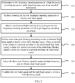
FIG. 2 is a flowchart that schematically shows a decoding method 200 according to an embodiment of the present invention. The decoding method 200 includes: differentiating a low frequency encoding parameter, a high frequency encoding parameter, and a high frequency gain from encoded information (210); performing decoding on the low frequency encoding parameter to obtain a low band signal (220); obtaining a synthesized high band signal according to the low frequency encoding parameter and the high frequency encoding parameter (230); performing short-time post-filtering processing on the synthesized high band signal to obtain a short-time filtering signal, where, compared with a shape of a spectral envelope of the synthesized high band signal, a shape of a spectral envelope of the short-time filtering signal is closer to a shape of a spectral envelope of a high band signal (240); adjusting the short-time filtering signal by using the high frequency gain to obtain a high band signal (250); and combining the low band signal and the high band signal to obtain a final decoding signal (260). - In 210, the low frequency encoding parameter, the high frequency encoding parameter, and the high frequency gain are differentiated from the encoded information. The low frequency encoding parameter may include, for example, an algebraic codebook, an algebraic codebook gain, an adaptive codebook, an adaptive codebook gain, a pitch period, and another parameter, and the high frequency encoding parameter may include, for example, an LPC coefficient and another parameter. In addition, the low frequency encoding parameter and the high frequency encoding parameter may alternatively include another parameter according to a different encoding technology.
- In 220, decoding is performed on the low frequency encoding parameter to obtain the low band signal. A specific decoding manner corresponds to an encoding manner of an encoder side. For example, when an ACELP encoder that uses an ACELP algorithm is used at the encoder side to perform encoding, in 220, an ACELP decoder is used to obtain the low band signal.
- In 230, the synthesized high band signal is obtained according to the low frequency encoding parameter and the high frequency encoding parameter. For example, the low frequency encoding parameter is used to restore a high frequency excitation signal, the LPC coefficient in the high frequency encoding parameter is used to generate a synthesized filter, and the synthesized filter is used to perform filtering on the high frequency excitation signal to obtain the synthesized high band signal. In practice, another technology may further be adopted according to a requirement so as to obtain the synthesized high band signal based on the low frequency encoding parameter and the high frequency encoding parameter.
- As described above, in a process of obtaining the synthesized high band signal according to the low frequency encoding parameter and the high frequency encoding parameter, a frequency spectrum of the high frequency excitation signal that is obtained by using the low frequency encoding parameter to perform a prediction is flat, however, a frequency spectrum of an actual high frequency excitation signal is not flat. This difference causes that the spectral envelope of the synthesized high band signal does not change with a spectral envelope of the high band signal in an original signal, and further causes a rustle in a restored speech signal.
- In 240, the short-time post-filtering processing is performed on the synthesized high band signal to obtain the short-time filtering signal, where, compared with the shape of the spectral envelope of the synthesized high band signal, the shape of the spectral envelope of the short-time filtering signal is closer to the shape of the spectral envelope of the high band signal.
- For example, a filter that is used to perform post-filtering processing on the synthesized high band signal may be formed based on the high frequency encoding parameter, and the filter is used to perform filtering on the synthesized high band signal to obtain a short-time filtering signal, where, compared with the synthesized high band signal, the shape of the spectral envelope of the short-time filtering signal is closer to the shape of the spectral envelope of the high band signal. For example, a coefficient of a pole-zero post-filter may be set based on the high frequency encoding parameter, and the pole-zero post-filter may be used to perform filtering processing on the synthesized high band signal. Alternatively, a coefficient of an all-pole post-filter may be set based on the high frequency encoding parameter, and the all-pole post-filter may be used to perform filtering processing on the synthesized high band signal.
- In a case in which encoding is performed on the high band signal by using a linear predictive coding LPC technology, the high frequency encoding parameter includes an LPC coefficient a 1, a 2,......aM , M is an order of the LPC coefficient, a z-domain transfer function of a pole-zero post-filter that is set based on the LPC coefficient may be the foregoing formula (1), and a z-domain transfer function of an all-pole post-filter that is set based on the LPC coefficient may be the foregoing formula (3). Compared with a shape of a spectral envelope of a synthesized high band signal that has not been processed by the pole-zero post-filter (or the all-pole post-filter), a shape of a spectral envelope of a synthesized high band signal that has been processed by the pole-zero post-filter (or the all-pole post-filter) is closer to a shape of a spectral envelope of an original high band signal, which avoids a rustle in a restored signal, thereby improving an encoding effect.
- In addition, as described above, the synthesized high band signal after the pole-zero post-filtering processing shown in formula (1) has a low-pass effect, therefore, after the filtering processing is performed on the synthesized high band signal by using the pole-zero post-filter, processing may further be performed by using a first-order filter whose z-domain transfer function is the foregoing formula (2), so as to further improve the encoding effect.
- For description of 240, reference may be made to the foregoing description that is of 140 and is performed with reference to
FIG. 1 . - In 250, the high frequency gain is used to adjust the short-time filtering signal to obtain the high band signal. Corresponding to that, at the decoder side, the high frequency gain is obtained by using the high band signal and the short-time filtering signal (150 in
FIG. 1 ), in 250, the high frequency gain is used to adjust the short-time filtering signal to restore the high band signal. - In 260, the low band signal and the high band signal are combined to obtain the final decoding signal (260). This combination manner corresponds to a dividing manner in 110 of
FIG. 1 , thereby implementing decoding to obtain a final output signal. - In the foregoing decoding method according to this embodiment of the present invention, short-time post-filtering processing is performed on a synthesized high band signal to obtain a short-time filtering signal, and a high frequency gain is calculated based on the short-time filtering signal, which can reduce or even remove a rustle from a restored signal, and improve a decoding effect.
-
FIG. 3 is block diagram that schematically shows an example of anencoding apparatus 300. Theencoding apparatus 300 includes: adivision unit 310, configured to divide a to-be-encoded time-domain signal into a low band signal and a high band signal; a low frequency encoding unit, configured to perform encoding on the low band signal to obtain a lowfrequency encoding parameter 320; a highfrequency encoding unit 330, configured to perform encoding on the high band signal to obtain a high frequency encoding parameter; asynthesizing unit 340, configured to obtain a synthesized high band signal according to the low frequency encoding parameter and the high frequency encoding parameter; afiltering unit 350, configured to perform short-time post-filtering processing on the synthesized high band signal to obtain a short-time filtering signal, where, compared with a shape of a spectral envelope of the synthesized high band signal, a shape of a spectral envelope of the short-time filtering signal is closer to a shape of a spectral envelope of the high band signal; and acalculation unit 360, configured to calculate a high frequency gain based on the high band signal and the short-time filtering signal. - After receiving an input time-domain signal, the
division unit 310 divides the to-be-encoded time-domain signal into two signals (a low band signal and a high band signal) to perform processing. The division may be implemented by using any conventional or future division technology. The meaning of the low frequency herein is relative to the meaning of the high frequency. For example, a frequency threshold may be set; where a frequency lower than the frequency threshold is a low frequency, and a frequency higher than the frequency threshold is a high frequency. In practice, the frequency threshold may be set according to a requirement, and a low band signal component and a high frequency component in a signal may also be differentiated by using another manner, so as to implement the division. - The low
frequency encoding unit 320 may use a proper encoding technology according to a requirement so as to perform encoding on the low band signal. For example, the lowfrequency encoding unit 320 may use an ACELP encoder to perform encoding so as to obtain the low frequency encoding parameter (which may include, for example, an algebraic codebook, an algebraic codebook gain, an adaptive codebook, an adaptive codebook gain, and a pitch period). When a used encoding technology changes, composition of the low frequency encoding parameter may also change. The obtained low frequency encoding parameter is a parameter required for restoring the low band signal, and the obtained low frequency encoding parameter is transferred to a decoder to restore the low band signal. - The high
frequency encoding unit 330 performs encoding on the high band signal to obtain a high frequency encoding parameter. For example, the highfrequency encoding unit 330 may perform linear predictive coding (LPC, Linear Prencdictive Coding) analysis on a high band signal in an original signal to obtain a high frequency encoding parameter such as an LPC coefficient. An encoding technology that is used to perform encoding on the high band signal constitutes no limitation on the embodiments of the present invention. - The synthesizing
unit 340 uses the low frequency encoding parameter to predict a high frequency excitation signal, and enables the high frequency excitation signal to pass to a synthesized filter that is determined according to the LPC coefficient so as to obtain the synthesized high band signal. In practice, another technology may further be adopted according to a requirement so as to obtain the synthesized high band signal according to the low frequency encoding parameter and the high frequency encoding parameter. A frequency spectrum of the high frequency excitation signal that is obtained by the synthesizingunit 340 by performing a prediction by using the low frequency encoding parameter is flat; however, a frequency spectrum of an actual high frequency excitation signal is not flat. This difference causes that the spectral envelope of the synthesized high band signal does not change with the spectral envelope of the high band signal in the original signal, and further causes a rustle in a restored speech signal. - The
filtering unit 350 is configured to perform short-time post-filtering processing on the synthesized high band signal to obtain the short-time filtering signal, where, compared with the shape of the spectral envelope of the synthesized high band signal, the shape of the spectral envelope of the short-time filtering signal is closer to the shape of the spectral envelope of the high band signal. The following describes thefiltering unit 350 with reference toFIG. 4 . -
FIG. 4 is a block diagram that schematically shows thefiltering unit 350 in the example of theencoding apparatus 300. - The
filtering unit 350 may include a pole-zero post-filter 410, which is configured to perform filtering processing on the synthesized high band signal, where a coefficient of the pole-zero post-filter may be set based on the high frequency encoding parameter. In a case in which the highfrequency encoding unit 330 performs encoding on the high band signal by using a linear predictive coding LPC technology, a z-domain transfer function of the pole-zeropost-filter 410 may be shown in the foregoing formula (1). A shape of a spectral envelope of the synthesized high band signal that is processed by the pole-zeropost-filter 410 is closer to the shape of the spectral envelope of the original high band signal, which avoids a rustle in a restored signal, thereby improving an encoding effect. Optionally, thefiltering unit 350 may further include a first-order filter 420, which is located behind the pole-zero post-filter. A z-domain transfer function of the first-order filter 420 may be shown in the foregoing formula (2). Compared with a short-time filtering signal that is obtained from filtering processing by the pole-zeropost-filter 410 only, a change of a spectral envelope of a short-time filtering signal that is obtained from filtering processing by both the pole-zeropost-filter 410 and the first-order filter 420 is closer to a change of the spectral envelope of the original high band signal, and an encoding effect can be further improved. - As a replacement of the
filtering unit 350 shown inFIG. 4 , an all-pole post-filter may further be used to perform short-time post-filtering processing to obtain the short-time filtering signal, where, compared with the shape of the spectral envelope of the synthesized high band signal, the shape of the spectral envelope of the short-time filtering signal is closer to the shape of the spectral envelope of the high band signal. In a case in which encoding is performed on the high band signal by using the linear predictive coding LPC technology, a z-domain transfer function of the all-pole post-filter may be shown in the foregoing formula (3). - For description of the
filtering unit 350, reference may be made to the foregoing description that is of 140 and is performed with reference toFIG. 1 . - The
calculation unit 360 calculates the high frequency gain based on the high band signal that is provided by the division unit and the short-time filtering signal that is output by thefiltering unit 350. The high frequency gain and the low frequency encoding parameter and the high frequency encoding parameter together constitute encoding information, which is used for signal restoration at a decoder side. - In addition, the
encoding apparatus 300 may further include a bitstream generating unit, where the bitstream generating unit is configured to generate an encoding bitstream according to the low frequency encoding parameter, the high frequency encoding parameter, and the high frequency gain. The decoder side that receives the encoding bitstream may perform decoding based on the low frequency encoding parameter, the high frequency encoding parameter, and the high frequency gain. For operations that are performed by units of the encoding apparatus shown inFIG. 3 , reference may be made to the description that is of the encoding method and is performed with reference toFIG. 1 . - In the foregoing
encoding apparatus 300 according to this example , short-time post-filtering processing is performed on a synthesized high band signal to obtain a short-time filtering signal, and a high frequency gain is calculated based on the short-time filtering signal, which can reduce or even remove a rustle from a restored signal, and improve an encoding effect. -
FIG. 5 is a block diagram that schematically shows adecoding apparatus 500 according to an embodiment of the present invention. Thedecoding apparatus 500 includes: a differentiatingunit 510, configured to differentiate a low frequency encoding parameter, a high frequency encoding parameter, and a high frequency gain from encoded information; a lowfrequency decoding unit 520, configured to perform decoding on the low frequency encoding parameter to obtain a low band signal; asynthesizing unit 530, configured to obtain a synthesized high band signal according to the low frequency encoding parameter and the high frequency encoding parameter; afiltering unit 540, configured to perform short-time post-filtering processing on the synthesized high band signal to obtain a short-time filtering signal, where, compared with a shape of a spectral envelope of the synthesized high band signal, a shape of a spectral envelope of the short-time filtering signal is closer to a shape of a spectral envelope of the high band signal; a highfrequency decoding unit 550, configured to adjust the short-time filtering signal by using the high frequency gain to obtain a high band signal; and a combiningunit 560, configured to combine the low band signal and the high band signal to obtain a final decoding signal. - The differentiating
unit 510 differentiates the low frequency encoding parameter, the high frequency encoding parameter, and the high frequency gain from encoded information. The low frequency encoding parameter may include, for example, an algebraic codebook, an algebraic codebook gain, an adaptive codebook, an adaptive codebook gain, a pitch period, and another parameter, and the high frequency encoding parameter may include, for example, an LPC coefficient and another parameter. In addition, the low frequency encoding parameter and the high frequency encoding parameter may alternatively include another parameter according to a different encoding technology. - The low
frequency decoding unit 520 uses a decoding manner corresponding to an encoding manner of an encoder side, and performs decoding on the low frequency encoding parameter to obtain the low band signal. For example, when an ACELP encoder is used at the encoder side to perform encoding, the lowfrequency decoding unit 520 uses an ACELP decoder to obtain the low band signal. - That an LPC coefficient (that is, the high frequency encoding parameter) is obtained by using LPC analysis is used as an example. The synthesizing
unit 530 uses the low frequency encoding parameter to restore a high frequency excitation signal, uses the LPC coefficient to generate a synthesized filter, and uses the synthesized filter to perform filtering on the high frequency excitation signal to obtain the synthesized high band signal. In practice, another technology may further be adopted according to a requirement so as to obtain the synthesized high band signal based on the low frequency encoding parameter and the high frequency encoding parameter. - A frequency spectrum of the high frequency excitation signal that is obtained by the synthesizing
unit 530 by performing a prediction by using the low frequency encoding parameter is flat; however, a frequency spectrum of an actual high frequency excitation signal is not flat. This difference causes that the spectral envelope of the synthesized high band signal does not change with the spectral envelope of the high band signal in an original signal, and further causes a rustle in a restored speech signal. - For example, a structure of the
filtering unit 540 may be shown inFIG. 4 . Alternatively, thefiltering unit 540 may further use an all-pole post-filter to perform short-time post-filtering processing. In a case in which encoding is performed on the high band signal by using a linear predictive coding LPC technology, a z-domain transfer function of the all-pole post-filter may be shown in the foregoing formula (3). Thefiltering unit 540 is the same as thefiltering unit 350 inFIG. 3 ; therefore, reference may be made to the foregoing description that is performed with reference to thefiltering unit 350. - Corresponding to an operation, in an
encoding apparatus 300, of calculating a high frequency gain based on a high band signal and a short-time filtering signal, the highfrequency decoding unit 550 uses the high frequency gain to adjust the short-time filtering signal so as to obtain the high band signal. - In a combining manner corresponding to a dividing manner used by the division unit in the
encoding apparatus 300, the combiningunit 560 combines the low band signal and the high band signal, thereby implementing decoding and obtaining a final output signal. - In the foregoing
decoding apparatus 500 according to this embodiment of the present invention, short-time post-filtering processing is performed on a synthesized high band signal to obtain a short-time filtering signal, and a high frequency gain is calculated based on the short-time filtering signal, which can reduce or even remove a rustle from a restored signal, and improve a decoding effect. -
FIG. 6 is a diagram block that schematically shows an example of atransmitter 600 . Thetransmitter 600 inFIG. 6 may include anencoding apparatus 300 shown inFIG. 3 , and therefore, repeated description is omitted as appropriate. In addition, thetransmitter 600 may further include a transmitunit 610, which is configured to allocate bits to a high frequency encoding parameter and a low frequency encoding parameter that are generated by theencoding apparatus 300, so as to generate a bit stream, and transmit the bit stream. -
FIG. 7 is a block diagram that schematically shows an example of areceiver 700 . Thereceiver 700 inFIG. 7 may include adecoding apparatus 500 shown inFIG. 5 , and therefore, repeated description is omitted as appropriate. In addition, thereceiver 700 may further include a receiveunit 710, which is configured to receive an encoding signal for processing by thedecoding apparatus 500. - In another example, a communications system is further provided, which may include a
transmitter 600 that is described with reference toFIG. 6 or areceiver 700 that is described with reference toFIG. 7 . -
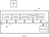
FIG. 8 is a schematic block diagram of an apparatus according to another example. Anapparatus 800 ofFIG. 8 may be used to implement steps and methods in the foregoing method embodiments. Theapparatus 800 may be applied to a base station or a terminal in various communications systems. In the embodiment ofFIG. 8 , theapparatus 800 includes a transmittingcircuit 802, a receivingcircuit 803, anencoding processor 804, adecoding processor 805, aprocessing unit 806, amemory 807, and anantenna 801. Theprocessing unit 806 controls an operation of theapparatus 800, and theprocessing unit 806 may further be referred to as a CPU (Central Processing Unit, central processing unit). Thememory 807 may include a read-only memory and a random access memory, and provides an instruction and data for theprocessing unit 806. A part of thememory 807 may further include a nonvolatile random access memory (NVRAM). In a specific application, theapparatus 800 may be built in a wireless communications device or theapparatus 800 itself may be a wireless communications device, such as a mobile phone, and theapparatus 800 may further include a carrier that accommodates the transmittingcircuit 802 and the receivingcircuit 803, so as to allow data transmitting and receiving between theapparatus 800 and a remote location. The transmittingcircuit 802 and the receivingcircuit 803 may be coupled to theantenna 801. Components of theapparatus 800 are coupled together by using abus system 809, where in addition to a data bus, thebus system 809 further includes a power bus, a control bus, and a status signal bus. However, for clarity of description, various buses are marked as thebus system 809 in a figure. Theapparatus 800 may further include theprocessing unit 806 for processing a signal, and in addition, further includes theencoding processor 804 and thedecoding processor 805. - The encoding method disclosed in the foregoing examples may be applied to the
encoding processor 804 or be implemented by theencoding processor 804, and the decoding method disclosed in the foregoing embodiments of the present invention may be applied to thedecoding processor 805 or be implemented by thedecoding processor 805. Theencoding processor 804 or thedecoding processor 805 may be an integrated circuit chip and has a signal processing capability. In an implementation process, steps in the foregoing methods may be completed by means of an integrated logic circuit of hardware in theencoding processor 804 or thedecoding processor 805 or an instruction in a form of software. The instruction may be implemented or controlled by means of cooperation by theprocessor 806, and is used to execute the method disclosed in the embodiments of the present invention. The foregoing decoding processor may be a general purpose processor, a digital signal processor (DSP), an application-specific integrated circuit (ASIC), a field programmable gate array (FPGA) or another programmable logic component, a discrete gate or a transistor logic component, or a discrete hardware assembly, and can implement or execute methods, steps, and logical block diagrams disclosed in the embodiments of the present invention. The general purpose processor may be a microprocessor, and the processor may also be any conventional processor, decoder, and the like. Steps of the methods disclosed with reference to the embodiments of the present invention may be directly executed and completed by using a hardware decoding processor, or may be executed and completed by using a combination of hardware and software modules in the decoding processor. A software module may be located in a mature storage medium in the art, such as a random access memory, a flash memory, a read-only memory, a programmable read-only memory, an electrically-erasable programmable memory, or a register. The storage medium is located in thememory 807, and theencoding processor 804 or thedecoding processor 805 reads information from thememory 807, and completes the steps of the foregoing methods in combination with the hardware. For example, thememory 807 may store the obtained low frequency encoding parameter for use by theencoding processor 804 or thedecoding processor 805 during encoding or decoding. - For example, an
encoding apparatus 300 inFIG. 3 may be implemented by theencoding processor 804, and adecoding apparatus 500 inFIG. 5 may be implemented by thedecoding processor 805. - In addition, for example, a
transmitter 610 inFIG. 6 may be implemented by theencoding processor 804, the transmittingcircuit 802, theantenna 801, and the like. Areceiver 710 inFIG. 7 may be implemented by theantenna 801, the receivingcircuit 803, thedecoding processor 805, and the like. However, the foregoing example is merely exemplary, and is not intended to limit the embodiments of the present invention on this specific implementation manner. - Specifically, the
memory 807 stores an instruction that enables theprocessor 806 and/or theencoding processor 804 to implement the following operations: dividing a to-be-encoded time-domain signal into a low band signal and a high band signal; performing encoding on the low band signal to obtain a low frequency encoding parameter; performing encoding on the high band signal to obtain a high frequency encoding parameter, and obtaining a synthesized high band signal according to the low frequency encoding parameter and the high frequency encoding parameter; performing short-time post-filtering processing on the synthesized high band signal to obtain a short-time filtering signal, where, compared with a shape of a spectral envelope of the synthesized high band signal, a shape of a spectral envelope of the short-time filtering signal is closer to a shape of a spectral envelope of the high band signal; and calculating a high frequency gain based on the high band signal and the short-time filtering signal. Thememory 807 stores an instruction that enables theprocessor 806 or thedecoding processor 805 to implement the following operations: differentiating a low frequency encoding parameter, a high frequency encoding parameter, and a high frequency gain from encoded information; performing decoding on the low frequency encoding parameter to obtain a low band signal; obtaining a synthesized high band signal according to the low frequency encoding parameter and the high frequency encoding parameter; performing short-time post-filtering processing on the synthesized high band signal to obtain a short-time filtering signal, where, compared with a shape of a spectral envelope of the synthesized high band signal, a shape of a spectral envelope of the short-time filtering signal is closer to a shape of a spectral envelope of a high band signal; adjusting the short-time filtering signal by using the high frequency gain to obtain a high band signal; and combining the low band signal and the high band signal to obtain a final decoding signal. - The communications system or communications apparatus in an example may include a part of or all of the foregoing
encoding apparatus 300,transmitter 610,decoding apparatus 500,receiver 710, and the like. - A person of ordinary skill in the art may be aware that, in combination with the examples described in the embodiments disclosed in this specification, units and algorithm steps may be implemented by electronic hardware or a combination of computer software and electronic hardware. Whether the functions are performed by hardware or software depends on particular applications and design constraint conditions of the technical solutions. A person skilled in the art may use different methods to implement the described functions for each particular application, but it should not be considered that the implementation goes beyond the scope of the present invention.
- It may be clearly understood by a person skilled in the art that, for the purpose of convenient and brief description, for a detailed working process of the foregoing system, apparatus, and unit, reference may be made to a corresponding process in the foregoing method embodiments, and details are not described herein again.
- In the several embodiments provided in the present application, it should be understood that the disclosed system, apparatus, and method may be implemented in other manners. For example, the described apparatus embodiment is merely exemplary. For example, the unit division is merely logical function division and may be other division in actual implementation. For example, a plurality of units or components may be combined or integrated into another system, or some features may be ignored or not performed.
- The units described as separate parts may or may not be physically separate, and parts displayed as units may or may not be physical units, may be located in one position, or may be distributed on a plurality of network units. Some or all of the units may be selected according to actual needs to achieve the objectives of the solutions of the embodiments.
- The foregoing descriptions are merely specific implementation manners of the present invention, but are not intended to limit the protection scope of the present invention. Any variation or replacement readily figured out by a person skilled in the art within the technical scope disclosed in the present invention shall fall within the protection scope of the present invention. Therefore, the protection scope of the present invention shall be subject to the protection scope of the claims.
Claims (8)
- A decoding method for decoding a speech signal, comprising:differentiating a low frequency encoding parameter, a high frequency encoding parameter, and a high frequency gain from encoded information;performing decoding on the low frequency encoding parameter to obtain a low band signal;obtaining a synthesized high band signal according to the low frequency encoding parameter and the high frequency encoding parameter;the method being characterized by furtherperforming short-time post-filtering processing on the synthesized high band signal to obtain a short-time filtered signal, wherein, compared with the shape of a spectral envelope of the synthesized high band signal, the shape of a spectral envelope of the short-time filtered signal is closer to the shape of a spectral envelope of a high band signal;adjusting the short-time filtered signal by using the high frequency gain to obtain a high band signal; andcombining the low band signal and the high band signal to obtain a final decoding signal.
- The decoding method according to claim 1, wherein the performing short-time post-filtering processing on the synthesized high band signal comprises:setting a coefficient of a pole-zero post-filter based on the high frequency encoding parameter; andperforming filtering processing on the synthesized high band signal by using the pole-zero post-filter.
- The decoding method according to claim 2, wherein the performing short-time post-filtering processing on the synthesized high band signal further comprises:after performing filtering processing on the synthesized high band signal by using the pole-zero post-filter, performing, by using a first-order filter whose z-domain transfer function is H t(z) = 1- µz-1, filtering processing on the synthesized high band signal that has been processed by the pole-zero post-filter, whereinµ is a preset constant or a value obtained by adaptive calculation that is performed according to the high frequency encoding parameter and the synthesized high band signal.
- The decoding method according to claim 2 or 3, wherein the high frequency encoding parameter comprises an LPC coefficient that is obtained by performing encoding by using a linear predictive coding LPC technology, and a z-domain transfer function of the pole-zero post-filter is calculated by using the following formula:

- A decoding apparatus for decoding a speech signal, comprising:a differentiating unit (510), configured to differentiate a low frequency encoding parameter, a high frequency encoding parameter, and a high frequency gain from encoded information;a low frequency decoding unit (520), configured to perform decoding on the low frequency encoding parameter to obtain a low band signal;a synthesizing unit (530), configured to obtain a synthesized high band signal according to the low frequency encoding parameter and the high frequency encoding parameter;the apparatus being characterized by: a filtering unit (540), configured to perform short-time post-filtering processing on the synthesized high band signal to obtain a short-time filtered signal, wherein, compared with the shape of a spectral envelope of the synthesized high band signal, the shape of a spectral envelope of the short-time filtered signal is closer to the shape of a spectral envelope of a high band signal;a high frequency decoding unit (550), configured to adjust the short-time filtered signal by using the high frequency gain to obtain a high band signal; anda combining unit (560), configured to combine the low band signal and the high band signal to obtain a final decoding signal.
- The decoding apparatus according to claim 5, wherein the filtering unit comprises:a pole-zero post-filter, configured to perform filtering processing on the synthesized high band signal, whereina coefficient of the pole-zero post-filter is set based on the high frequency encoding parameter.
- The decoding apparatus according to claim 6, wherein the filtering unit further comprises:a first-order filter, which is located behind the pole-zero post-filter and whose z-domain transfer function is H t(z) = 1 - µz -1, configured to perform filtering processing on the synthesized high band signal that has been processed by the pole-zero post-filter, whereinµ is a preset constant or a value obtained by adaptive calculation that is performed according to the high frequency encoding parameter and the synthesized high band signal.
- The decoding apparatus according to claim 6 or 7, wherein the high frequency encoding parameter is an LPC coefficient that is obtained by using a linear predictive coding LPC technology, and a z-domain transfer function of the pole-zero post-filter is calculated by using the following formula:

Priority Applications (6)
| Application Number | Priority Date | Filing Date | Title |
|---|---|---|---|
| DK18182328.7T DK3486905T3 (en) | 2013-01-15 | 2013-07-25 | CODING METHOD, DECODING PROCEDURE, CODING DEVICE AND DECODING DEVICE |
| SI201331452T SI3203470T1 (en) | 2013-01-15 | 2013-07-25 | Speech decoding method and speech decoding apparatus |
| PL18182328T PL3486905T3 (en) | 2013-01-15 | 2013-07-25 | Encoding method, decoding method, encoding apparatus, and decoding apparatus |
| EP18182328.7A EP3486905B1 (en) | 2013-01-15 | 2013-07-25 | Encoding method, decoding method, encoding apparatus, and decoding apparatus |
| PL16193849T PL3203470T3 (en) | 2013-01-15 | 2013-07-25 | Speech decoding method and speech decoding apparatus |
| EP20173785.5A EP3764355B1 (en) | 2013-01-15 | 2013-07-25 | Encoding method, decoding method, encoding apparatus, and decoding apparatus |
Applications Claiming Priority (3)
| Application Number | Priority Date | Filing Date | Title |
|---|---|---|---|
| CN201310014342.4A CN103928031B (en) | 2013-01-15 | 2013-01-15 | Coding method, coding/decoding method, encoding apparatus and decoding apparatus |
| EP13872123.8A EP2905777B1 (en) | 2013-01-15 | 2013-07-25 | Encoding method, decoding method, encoding device, and decoding device |
| PCT/CN2013/080061 WO2014110895A1 (en) | 2013-01-15 | 2013-07-25 | Encoding method, decoding method, encoding device, and decoding device |
Related Parent Applications (2)
| Application Number | Title | Priority Date | Filing Date |
|---|---|---|---|
| EP13872123.8A Division EP2905777B1 (en) | 2013-01-15 | 2013-07-25 | Encoding method, decoding method, encoding device, and decoding device |
| EP13872123.8A Division-Into EP2905777B1 (en) | 2013-01-15 | 2013-07-25 | Encoding method, decoding method, encoding device, and decoding device |
Related Child Applications (3)
| Application Number | Title | Priority Date | Filing Date |
|---|---|---|---|
| EP18182328.7A Division-Into EP3486905B1 (en) | 2013-01-15 | 2013-07-25 | Encoding method, decoding method, encoding apparatus, and decoding apparatus |
| EP18182328.7A Division EP3486905B1 (en) | 2013-01-15 | 2013-07-25 | Encoding method, decoding method, encoding apparatus, and decoding apparatus |
| EP20173785.5A Division EP3764355B1 (en) | 2013-01-15 | 2013-07-25 | Encoding method, decoding method, encoding apparatus, and decoding apparatus |
Publications (2)
| Publication Number | Publication Date |
|---|---|
| EP3203470A1 EP3203470A1 (en) | 2017-08-09 |
| EP3203470B1 true EP3203470B1 (en) | 2019-03-13 |
Family
ID=51146229
Family Applications (4)
| Application Number | Title | Priority Date | Filing Date |
|---|---|---|---|
| EP20173785.5A Active EP3764355B1 (en) | 2013-01-15 | 2013-07-25 | Encoding method, decoding method, encoding apparatus, and decoding apparatus |
| EP18182328.7A Active EP3486905B1 (en) | 2013-01-15 | 2013-07-25 | Encoding method, decoding method, encoding apparatus, and decoding apparatus |
| EP13872123.8A Active EP2905777B1 (en) | 2013-01-15 | 2013-07-25 | Encoding method, decoding method, encoding device, and decoding device |
| EP16193849.3A Active EP3203470B1 (en) | 2013-01-15 | 2013-07-25 | Speech decoding method and speech decoding apparatus |
Family Applications Before (3)
| Application Number | Title | Priority Date | Filing Date |
|---|---|---|---|
| EP20173785.5A Active EP3764355B1 (en) | 2013-01-15 | 2013-07-25 | Encoding method, decoding method, encoding apparatus, and decoding apparatus |
| EP18182328.7A Active EP3486905B1 (en) | 2013-01-15 | 2013-07-25 | Encoding method, decoding method, encoding apparatus, and decoding apparatus |
| EP13872123.8A Active EP2905777B1 (en) | 2013-01-15 | 2013-07-25 | Encoding method, decoding method, encoding device, and decoding device |
Country Status (17)
| Country | Link |
|---|---|
| US (5) | US9761235B2 (en) |
| EP (4) | EP3764355B1 (en) |
| JP (3) | JP6141443B2 (en) |
| KR (2) | KR101966265B1 (en) |
| CN (2) | CN103928031B (en) |
| BR (1) | BR112015013088B1 (en) |
| DK (3) | DK3203470T3 (en) |
| ES (3) | ES2828004T3 (en) |
| HK (1) | HK1199541A1 (en) |
| HU (3) | HUE043649T2 (en) |
| NO (1) | NO2905777T3 (en) |
| PL (3) | PL2905777T3 (en) |
| PT (3) | PT3486905T (en) |
| SG (1) | SG11201503772RA (en) |
| SI (3) | SI2905777T1 (en) |
| TR (1) | TR201907656T4 (en) |
| WO (1) | WO2014110895A1 (en) |
Families Citing this family (6)
| Publication number | Priority date | Publication date | Assignee | Title |
|---|---|---|---|---|
| CN108172239B (en) | 2013-09-26 | 2021-01-12 | 华为技术有限公司 | Method and device for expanding frequency band |
| CN106228991B (en) * | 2014-06-26 | 2019-08-20 | 华为技术有限公司 | Decoding method, apparatus and system |
| US10475457B2 (en) * | 2017-07-03 | 2019-11-12 | Qualcomm Incorporated | Time-domain inter-channel prediction |
| JP7362320B2 (en) * | 2019-07-04 | 2023-10-17 | フォルシアクラリオン・エレクトロニクス株式会社 | Audio signal processing device, audio signal processing method, and audio signal processing program |
| US10978083B1 (en) * | 2019-11-13 | 2021-04-13 | Shure Acquisition Holdings, Inc. | Time domain spectral bandwidth replication |
| CN113079378B (en) * | 2021-04-15 | 2022-08-16 | 杭州海康威视数字技术股份有限公司 | Image processing method and device and electronic equipment |
Family Cites Families (38)
| Publication number | Priority date | Publication date | Assignee | Title |
|---|---|---|---|---|
| US4969192A (en) | 1987-04-06 | 1990-11-06 | Voicecraft, Inc. | Vector adaptive predictive coder for speech and audio |
| US5307441A (en) | 1989-11-29 | 1994-04-26 | Comsat Corporation | Wear-toll quality 4.8 kbps speech codec |
| US5495555A (en) | 1992-06-01 | 1996-02-27 | Hughes Aircraft Company | High quality low bit rate celp-based speech codec |
| FR2720850B1 (en) * | 1994-06-03 | 1996-08-14 | Matra Communication | Linear prediction speech coding method. |
| JPH08160996A (en) * | 1994-12-05 | 1996-06-21 | Hitachi Ltd | Voice encoding device |
| DE69628103T2 (en) * | 1995-09-14 | 2004-04-01 | Kabushiki Kaisha Toshiba, Kawasaki | Method and filter for highlighting formants |
| US5864798A (en) * | 1995-09-18 | 1999-01-26 | Kabushiki Kaisha Toshiba | Method and apparatus for adjusting a spectrum shape of a speech signal |
| DE19643900C1 (en) * | 1996-10-30 | 1998-02-12 | Ericsson Telefon Ab L M | Audio signal post filter, especially for speech signals |
| FR2783651A1 (en) * | 1998-09-22 | 2000-03-24 | Koninkl Philips Electronics Nv | DEVICE AND METHOD FOR FILTERING A SPEECH SIGNAL, RECEIVER AND TELEPHONE COMMUNICATIONS SYSTEM |
| US6377915B1 (en) * | 1999-03-17 | 2002-04-23 | Yrp Advanced Mobile Communication Systems Research Laboratories Co., Ltd. | Speech decoding using mix ratio table |
| US6510407B1 (en) * | 1999-10-19 | 2003-01-21 | Atmel Corporation | Method and apparatus for variable rate coding of speech |
| DE10041512B4 (en) | 2000-08-24 | 2005-05-04 | Infineon Technologies Ag | Method and device for artificially expanding the bandwidth of speech signals |
| DE60208426T2 (en) | 2001-11-02 | 2006-08-24 | Matsushita Electric Industrial Co., Ltd., Kadoma | DEVICE FOR SIGNAL CODING, SIGNAL DECODING AND SYSTEM FOR DISTRIBUTING AUDIO DATA |
| AU2002352182A1 (en) | 2001-11-29 | 2003-06-10 | Coding Technologies Ab | Methods for improving high frequency reconstruction |
| CA2415105A1 (en) * | 2002-12-24 | 2004-06-24 | Voiceage Corporation | A method and device for robust predictive vector quantization of linear prediction parameters in variable bit rate speech coding |
| US20050004793A1 (en) | 2003-07-03 | 2005-01-06 | Pasi Ojala | Signal adaptation for higher band coding in a codec utilizing band split coding |
| CA2457988A1 (en) * | 2004-02-18 | 2005-08-18 | Voiceage Corporation | Methods and devices for audio compression based on acelp/tcx coding and multi-rate lattice vector quantization |
| EP1872364B1 (en) * | 2005-03-30 | 2010-11-24 | Nokia Corporation | Source coding and/or decoding |
| NZ562188A (en) | 2005-04-01 | 2010-05-28 | Qualcomm Inc | Methods and apparatus for encoding and decoding an highband portion of a speech signal |
| ES2350494T3 (en) * | 2005-04-01 | 2011-01-24 | Qualcomm Incorporated | PROCEDURE AND APPLIANCES FOR CODING AND DECODING A HIGH BAND PART OF A SPEAKING SIGNAL. |
| US8892448B2 (en) * | 2005-04-22 | 2014-11-18 | Qualcomm Incorporated | Systems, methods, and apparatus for gain factor smoothing |
| US7707034B2 (en) | 2005-05-31 | 2010-04-27 | Microsoft Corporation | Audio codec post-filter |
| KR100795727B1 (en) * | 2005-12-08 | 2008-01-21 | 한국전자통신연구원 | A method and apparatus that searches a fixed codebook in speech coder based on CELP |
| KR20070115637A (en) | 2006-06-03 | 2007-12-06 | 삼성전자주식회사 | Method and apparatus for bandwidth extension encoding and decoding |
| US8135047B2 (en) | 2006-07-31 | 2012-03-13 | Qualcomm Incorporated | Systems and methods for including an identifier with a packet associated with a speech signal |
| US9454974B2 (en) * | 2006-07-31 | 2016-09-27 | Qualcomm Incorporated | Systems, methods, and apparatus for gain factor limiting |
| WO2008022184A2 (en) * | 2006-08-15 | 2008-02-21 | Broadcom Corporation | Constrained and controlled decoding after packet loss |
| CN101140759B (en) * | 2006-09-08 | 2010-05-12 | 华为技术有限公司 | Band-width spreading method and system for voice or audio signal |
| US8239191B2 (en) * | 2006-09-15 | 2012-08-07 | Panasonic Corporation | Speech encoding apparatus and speech encoding method |
| WO2008072671A1 (en) | 2006-12-13 | 2008-06-19 | Panasonic Corporation | Audio decoding device and power adjusting method |
| JP4984983B2 (en) | 2007-03-09 | 2012-07-25 | 富士通株式会社 | Encoding apparatus and encoding method |
| EP2051245A3 (en) * | 2007-10-17 | 2013-07-10 | Gwangju Institute of Science and Technology | Wideband audio signal coding/decoding device and method |
| KR101452722B1 (en) * | 2008-02-19 | 2014-10-23 | 삼성전자주식회사 | Method and apparatus for encoding and decoding signal |
| JP4932917B2 (en) | 2009-04-03 | 2012-05-16 | 株式会社エヌ・ティ・ティ・ドコモ | Speech decoding apparatus, speech decoding method, and speech decoding program |
| RU2568278C2 (en) | 2009-11-19 | 2015-11-20 | Телефонактиеболагет Лм Эрикссон (Пабл) | Bandwidth extension for low-band audio signal |
| US8886523B2 (en) * | 2010-04-14 | 2014-11-11 | Huawei Technologies Co., Ltd. | Audio decoding based on audio class with control code for post-processing modes |
| US8600737B2 (en) * | 2010-06-01 | 2013-12-03 | Qualcomm Incorporated | Systems, methods, apparatus, and computer program products for wideband speech coding |
| DK2791937T3 (en) * | 2011-11-02 | 2016-09-12 | ERICSSON TELEFON AB L M (publ) | Generation of an højbåndsudvidelse of a broadband extended buzzer |
-
2013
- 2013-01-15 CN CN201310014342.4A patent/CN103928031B/en active Active
- 2013-01-15 CN CN201610112075.8A patent/CN105551497B/en active Active
- 2013-07-25 SG SG11201503772RA patent/SG11201503772RA/en unknown
- 2013-07-25 DK DK16193849.3T patent/DK3203470T3/en active
- 2013-07-25 EP EP20173785.5A patent/EP3764355B1/en active Active
- 2013-07-25 EP EP18182328.7A patent/EP3486905B1/en active Active
- 2013-07-25 HU HUE16193849A patent/HUE043649T2/en unknown
- 2013-07-25 PT PT181823287T patent/PT3486905T/en unknown
- 2013-07-25 PL PL13872123T patent/PL2905777T3/en unknown
- 2013-07-25 PT PT16193849T patent/PT3203470T/en unknown
- 2013-07-25 PT PT138721238T patent/PT2905777T/en unknown
- 2013-07-25 DK DK18182328.7T patent/DK3486905T3/en active
- 2013-07-25 ES ES18182328T patent/ES2828004T3/en active Active
- 2013-07-25 PL PL16193849T patent/PL3203470T3/en unknown
- 2013-07-25 PL PL18182328T patent/PL3486905T3/en unknown
- 2013-07-25 TR TR2019/07656T patent/TR201907656T4/en unknown
- 2013-07-25 NO NO13872123A patent/NO2905777T3/no unknown
- 2013-07-25 KR KR1020157014971A patent/KR101966265B1/en active IP Right Grant
- 2013-07-25 HU HUE18182328A patent/HUE051171T2/en unknown
- 2013-07-25 EP EP13872123.8A patent/EP2905777B1/en active Active
- 2013-07-25 HU HUE13872123A patent/HUE036710T2/en unknown
- 2013-07-25 EP EP16193849.3A patent/EP3203470B1/en active Active
- 2013-07-25 JP JP2015546810A patent/JP6141443B2/en active Active
- 2013-07-25 KR KR1020167019767A patent/KR101748303B1/en active IP Right Grant
- 2013-07-25 DK DK13872123.8T patent/DK2905777T3/en active
- 2013-07-25 ES ES13872123.8T patent/ES2637741T3/en active Active
- 2013-07-25 WO PCT/CN2013/080061 patent/WO2014110895A1/en active Application Filing
- 2013-07-25 BR BR112015013088A patent/BR112015013088B1/en active IP Right Grant
- 2013-07-25 ES ES16193849T patent/ES2728000T3/en active Active
- 2013-07-25 SI SI201330810T patent/SI2905777T1/en unknown
- 2013-07-25 SI SI201331452T patent/SI3203470T1/en unknown
- 2013-07-25 SI SI201331808T patent/SI3486905T1/en unknown
-
2014
- 2014-12-30 HK HK14113072.8A patent/HK1199541A1/en unknown
-
2015
- 2015-05-26 US US14/721,606 patent/US9761235B2/en active Active
-
2017
- 2017-05-01 JP JP2017091250A patent/JP6397082B2/en active Active
- 2017-08-15 US US15/677,324 patent/US10210880B2/en active Active
-
2018
- 2018-08-30 JP JP2018161132A patent/JP6616470B2/en active Active
-
2019
- 2019-01-03 US US16/238,797 patent/US10770085B2/en active Active
-
2020
- 2020-08-21 US US16/999,448 patent/US11430456B2/en active Active
-
2022
- 2022-07-20 US US17/868,879 patent/US11869520B2/en active Active
Non-Patent Citations (1)
| Title |
|---|
| None * |
Also Published As
Similar Documents
| Publication | Publication Date | Title |
|---|---|---|
| US11430456B2 (en) | Encoding method, decoding method, encoding apparatus, and decoding apparatus | |
| EP2899721B1 (en) | Audio signal encoding/decoding method and audio signal encoding/decoding device | |
| EP2991074A1 (en) | Signal decoding method and device | |
| EP3595211A1 (en) | Method for processing lost frame, and decoder |
Legal Events
| Date | Code | Title | Description |
|---|---|---|---|
| PUAI | Public reference made under article 153(3) epc to a published international application that has entered the european phase |
Free format text: ORIGINAL CODE: 0009012 |
|
| STAA | Information on the status of an ep patent application or granted ep patent |
Free format text: STATUS: THE APPLICATION HAS BEEN PUBLISHED |
|
| AC | Divisional application: reference to earlier application |
Ref document number: 2905777 Country of ref document: EP Kind code of ref document: P |
|
| AK | Designated contracting states |
Kind code of ref document: A1 Designated state(s): AL AT BE BG CH CY CZ DE DK EE ES FI FR GB GR HR HU IE IS IT LI LT LU LV MC MK MT NL NO PL PT RO RS SE SI SK SM TR |
|
| STAA | Information on the status of an ep patent application or granted ep patent |
Free format text: STATUS: REQUEST FOR EXAMINATION WAS MADE |
|
| 17P | Request for examination filed |
Effective date: 20180209 |
|
| RBV | Designated contracting states (corrected) |
Designated state(s): AL AT BE BG CH CY CZ DE DK EE ES FI FR GB GR HR HU IE IS IT LI LT LU LV MC MK MT NL NO PL PT RO RS SE SI SK SM TR |
|
| GRAP | Despatch of communication of intention to grant a patent |
Free format text: ORIGINAL CODE: EPIDOSNIGR1 |
|
| STAA | Information on the status of an ep patent application or granted ep patent |
Free format text: STATUS: GRANT OF PATENT IS INTENDED |
|
| RIC1 | Information provided on ipc code assigned before grant |
Ipc: G10L 19/02 20130101ALN20180226BHEP Ipc: G10L 21/038 20130101ALI20180226BHEP Ipc: G10L 19/26 20130101AFI20180226BHEP |
|
| INTG | Intention to grant announced |
Effective date: 20180323 |
|
| RAP1 | Party data changed (applicant data changed or rights of an application transferred) |
Owner name: HUAWEI TECHNOLOGIES CO., LTD. |
|
| RIN1 | Information on inventor provided before grant (corrected) |
Inventor name: LIU, ZEXIN Inventor name: WANG, BIN Inventor name: MIAO, LEI |
|
| GRAJ | Information related to disapproval of communication of intention to grant by the applicant or resumption of examination proceedings by the epo deleted |
Free format text: ORIGINAL CODE: EPIDOSDIGR1 |
|
| STAA | Information on the status of an ep patent application or granted ep patent |
Free format text: STATUS: REQUEST FOR EXAMINATION WAS MADE |
|
| INTC | Intention to grant announced (deleted) | ||
| RIC1 | Information provided on ipc code assigned before grant |
Ipc: G10L 19/26 20130101AFI20180807BHEP Ipc: G10L 21/038 20130101ALI20180807BHEP Ipc: G10L 19/02 20130101ALN20180807BHEP |
|
| GRAP | Despatch of communication of intention to grant a patent |
Free format text: ORIGINAL CODE: EPIDOSNIGR1 |
|
| STAA | Information on the status of an ep patent application or granted ep patent |
Free format text: STATUS: GRANT OF PATENT IS INTENDED |
|
| INTG | Intention to grant announced |
Effective date: 20180924 |
|
| GRAS | Grant fee paid |
Free format text: ORIGINAL CODE: EPIDOSNIGR3 |
|
| GRAA | (expected) grant |
Free format text: ORIGINAL CODE: 0009210 |
|
| STAA | Information on the status of an ep patent application or granted ep patent |
Free format text: STATUS: THE PATENT HAS BEEN GRANTED |
|
| AC | Divisional application: reference to earlier application |
Ref document number: 2905777 Country of ref document: EP Kind code of ref document: P |
|
| AK | Designated contracting states |
Kind code of ref document: B1 Designated state(s): AL AT BE BG CH CY CZ DE DK EE ES FI FR GB GR HR HU IE IS IT LI LT LU LV MC MK MT NL NO PL PT RO RS SE SI SK SM TR |
|
| REG | Reference to a national code |
Ref country code: GB Ref legal event code: FG4D |
|
| REG | Reference to a national code |
Ref country code: AT Ref legal event code: REF Ref document number: 1108802 Country of ref document: AT Kind code of ref document: T Effective date: 20190315 Ref country code: CH Ref legal event code: EP |
|
| REG | Reference to a national code |
Ref country code: IE Ref legal event code: FG4D |
|
| REG | Reference to a national code |
Ref country code: DE Ref legal event code: R096 Ref document number: 602013052509 Country of ref document: DE |
|
| REG | Reference to a national code |
Ref country code: DK Ref legal event code: T3 Effective date: 20190522 |
|
| REG | Reference to a national code |
Ref country code: SE Ref legal event code: TRGR |
|
| REG | Reference to a national code |
Ref country code: PT Ref legal event code: SC4A Ref document number: 3203470 Country of ref document: PT Date of ref document: 20190604 Kind code of ref document: T Free format text: AVAILABILITY OF NATIONAL TRANSLATION Effective date: 20190520 |
|
| REG | Reference to a national code |
Ref country code: NL Ref legal event code: FP |
|
| REG | Reference to a national code |
Ref country code: LT Ref legal event code: MG4D |
|
| PG25 | Lapsed in a contracting state [announced via postgrant information from national office to epo] |
Ref country code: LT Free format text: LAPSE BECAUSE OF FAILURE TO SUBMIT A TRANSLATION OF THE DESCRIPTION OR TO PAY THE FEE WITHIN THE PRESCRIBED TIME-LIMIT Effective date: 20190313 |
|
| REG | Reference to a national code |
Ref country code: NO Ref legal event code: T2 Effective date: 20190313 |
|
| REG | Reference to a national code |
Ref country code: EE Ref legal event code: FG4A Ref document number: E017682 Country of ref document: EE Effective date: 20190606 |
|
| REG | Reference to a national code |
Ref country code: HU Ref legal event code: AG4A Ref document number: E043649 Country of ref document: HU |
|
| PG25 | Lapsed in a contracting state [announced via postgrant information from national office to epo] |
Ref country code: RS Free format text: LAPSE BECAUSE OF FAILURE TO SUBMIT A TRANSLATION OF THE DESCRIPTION OR TO PAY THE FEE WITHIN THE PRESCRIBED TIME-LIMIT Effective date: 20190313 Ref country code: HR Free format text: LAPSE BECAUSE OF FAILURE TO SUBMIT A TRANSLATION OF THE DESCRIPTION OR TO PAY THE FEE WITHIN THE PRESCRIBED TIME-LIMIT Effective date: 20190313 Ref country code: LV Free format text: LAPSE BECAUSE OF FAILURE TO SUBMIT A TRANSLATION OF THE DESCRIPTION OR TO PAY THE FEE WITHIN THE PRESCRIBED TIME-LIMIT Effective date: 20190313 Ref country code: BG Free format text: LAPSE BECAUSE OF FAILURE TO SUBMIT A TRANSLATION OF THE DESCRIPTION OR TO PAY THE FEE WITHIN THE PRESCRIBED TIME-LIMIT Effective date: 20190613 |
|
| REG | Reference to a national code |
Ref country code: SK Ref legal event code: T3 Ref document number: E 31213 Country of ref document: SK |
|
| REG | Reference to a national code |
Ref country code: GR Ref legal event code: EP Ref document number: 20190401754 Country of ref document: GR Effective date: 20190906 |
|
| REG | Reference to a national code |
Ref country code: ES Ref legal event code: FG2A Ref document number: 2728000 Country of ref document: ES Kind code of ref document: T3 Effective date: 20191021 |
|
| PG25 | Lapsed in a contracting state [announced via postgrant information from national office to epo] |
Ref country code: AL Free format text: LAPSE BECAUSE OF FAILURE TO SUBMIT A TRANSLATION OF THE DESCRIPTION OR TO PAY THE FEE WITHIN THE PRESCRIBED TIME-LIMIT Effective date: 20190313 Ref country code: RO Free format text: LAPSE BECAUSE OF FAILURE TO SUBMIT A TRANSLATION OF THE DESCRIPTION OR TO PAY THE FEE WITHIN THE PRESCRIBED TIME-LIMIT Effective date: 20190313 |
|
| PG25 | Lapsed in a contracting state [announced via postgrant information from national office to epo] |
Ref country code: SM Free format text: LAPSE BECAUSE OF FAILURE TO SUBMIT A TRANSLATION OF THE DESCRIPTION OR TO PAY THE FEE WITHIN THE PRESCRIBED TIME-LIMIT Effective date: 20190313 |
|
| REG | Reference to a national code |
Ref country code: DE Ref legal event code: R097 Ref document number: 602013052509 Country of ref document: DE |
|
| PLBE | No opposition filed within time limit |
Free format text: ORIGINAL CODE: 0009261 |
|
| STAA | Information on the status of an ep patent application or granted ep patent |
Free format text: STATUS: NO OPPOSITION FILED WITHIN TIME LIMIT |
|
| 26N | No opposition filed |
Effective date: 20191216 |
|
| PG25 | Lapsed in a contracting state [announced via postgrant information from national office to epo] |
Ref country code: MC Free format text: LAPSE BECAUSE OF FAILURE TO SUBMIT A TRANSLATION OF THE DESCRIPTION OR TO PAY THE FEE WITHIN THE PRESCRIBED TIME-LIMIT Effective date: 20190313 |
|
| REG | Reference to a national code |
Ref country code: AT Ref legal event code: UEP Ref document number: 1108802 Country of ref document: AT Kind code of ref document: T Effective date: 20190313 |
|
| PG25 | Lapsed in a contracting state [announced via postgrant information from national office to epo] |
Ref country code: CY Free format text: LAPSE BECAUSE OF FAILURE TO SUBMIT A TRANSLATION OF THE DESCRIPTION OR TO PAY THE FEE WITHIN THE PRESCRIBED TIME-LIMIT Effective date: 20190313 |
|
| PG25 | Lapsed in a contracting state [announced via postgrant information from national office to epo] |
Ref country code: MT Free format text: LAPSE BECAUSE OF FAILURE TO SUBMIT A TRANSLATION OF THE DESCRIPTION OR TO PAY THE FEE WITHIN THE PRESCRIBED TIME-LIMIT Effective date: 20190313 |
|
| PG25 | Lapsed in a contracting state [announced via postgrant information from national office to epo] |
Ref country code: MK Free format text: LAPSE BECAUSE OF FAILURE TO SUBMIT A TRANSLATION OF THE DESCRIPTION OR TO PAY THE FEE WITHIN THE PRESCRIBED TIME-LIMIT Effective date: 20190313 |
|
| P01 | Opt-out of the competence of the unified patent court (upc) registered |
Effective date: 20230524 |
|
| PGFP | Annual fee paid to national office [announced via postgrant information from national office to epo] |
Ref country code: NL Payment date: 20230614 Year of fee payment: 11 Ref country code: IT Payment date: 20230612 Year of fee payment: 11 Ref country code: IE Payment date: 20230606 Year of fee payment: 11 Ref country code: FR Payment date: 20230620 Year of fee payment: 11 Ref country code: EE Payment date: 20230605 Year of fee payment: 11 Ref country code: DK Payment date: 20230627 Year of fee payment: 11 Ref country code: CZ Payment date: 20230629 Year of fee payment: 11 |
|
| PGFP | Annual fee paid to national office [announced via postgrant information from national office to epo] |
Ref country code: SK Payment date: 20230612 Year of fee payment: 11 Ref country code: SE Payment date: 20230613 Year of fee payment: 11 Ref country code: PL Payment date: 20230616 Year of fee payment: 11 Ref country code: LU Payment date: 20230714 Year of fee payment: 11 Ref country code: IS Payment date: 20230611 Year of fee payment: 11 Ref country code: GR Payment date: 20230613 Year of fee payment: 11 |
|
| PGFP | Annual fee paid to national office [announced via postgrant information from national office to epo] |
Ref country code: BE Payment date: 20230616 Year of fee payment: 11 |
|
| PGFP | Annual fee paid to national office [announced via postgrant information from national office to epo] |
Ref country code: TR Payment date: 20230724 Year of fee payment: 11 Ref country code: NO Payment date: 20230712 Year of fee payment: 11 Ref country code: GB Payment date: 20230601 Year of fee payment: 11 Ref country code: FI Payment date: 20230712 Year of fee payment: 11 Ref country code: ES Payment date: 20230809 Year of fee payment: 11 Ref country code: CH Payment date: 20230801 Year of fee payment: 11 Ref country code: AT Payment date: 20230626 Year of fee payment: 11 |
|
| PGFP | Annual fee paid to national office [announced via postgrant information from national office to epo] |
Ref country code: SI Payment date: 20230613 Year of fee payment: 11 Ref country code: PT Payment date: 20230724 Year of fee payment: 11 Ref country code: HU Payment date: 20230626 Year of fee payment: 11 Ref country code: DE Payment date: 20230531 Year of fee payment: 11 |