EP3203408B1 - Magnetic card reader and card reading method - Google Patents
Magnetic card reader and card reading method Download PDFInfo
- Publication number
- EP3203408B1 EP3203408B1 EP17154184.0A EP17154184A EP3203408B1 EP 3203408 B1 EP3203408 B1 EP 3203408B1 EP 17154184 A EP17154184 A EP 17154184A EP 3203408 B1 EP3203408 B1 EP 3203408B1
- Authority
- EP
- European Patent Office
- Prior art keywords
- magnetic
- card
- magnetic stripe
- spring
- stripe reader
- Prior art date
- Legal status (The legal status is an assumption and is not a legal conclusion. Google has not performed a legal analysis and makes no representation as to the accuracy of the status listed.)
- Not-in-force
Links
Images




Classifications
-
- G—PHYSICS
- G06—COMPUTING OR CALCULATING; COUNTING
- G06K—GRAPHICAL DATA READING; PRESENTATION OF DATA; RECORD CARRIERS; HANDLING RECORD CARRIERS
- G06K7/00—Methods or arrangements for sensing record carriers, e.g. for reading patterns
- G06K7/08—Methods or arrangements for sensing record carriers, e.g. for reading patterns by means detecting the change of an electrostatic or magnetic field, e.g. by detecting change of capacitance between electrodes
- G06K7/082—Methods or arrangements for sensing record carriers, e.g. for reading patterns by means detecting the change of an electrostatic or magnetic field, e.g. by detecting change of capacitance between electrodes using inductive or magnetic sensors
- G06K7/083—Methods or arrangements for sensing record carriers, e.g. for reading patterns by means detecting the change of an electrostatic or magnetic field, e.g. by detecting change of capacitance between electrodes using inductive or magnetic sensors inductive
-
- G—PHYSICS
- G06—COMPUTING OR CALCULATING; COUNTING
- G06K—GRAPHICAL DATA READING; PRESENTATION OF DATA; RECORD CARRIERS; HANDLING RECORD CARRIERS
- G06K7/00—Methods or arrangements for sensing record carriers, e.g. for reading patterns
- G06K7/08—Methods or arrangements for sensing record carriers, e.g. for reading patterns by means detecting the change of an electrostatic or magnetic field, e.g. by detecting change of capacitance between electrodes
- G06K7/082—Methods or arrangements for sensing record carriers, e.g. for reading patterns by means detecting the change of an electrostatic or magnetic field, e.g. by detecting change of capacitance between electrodes using inductive or magnetic sensors
- G06K7/083—Methods or arrangements for sensing record carriers, e.g. for reading patterns by means detecting the change of an electrostatic or magnetic field, e.g. by detecting change of capacitance between electrodes using inductive or magnetic sensors inductive
- G06K7/084—Methods or arrangements for sensing record carriers, e.g. for reading patterns by means detecting the change of an electrostatic or magnetic field, e.g. by detecting change of capacitance between electrodes using inductive or magnetic sensors inductive sensing magnetic material by relative movement detecting flux changes without altering its magnetised state
Definitions
- the invention relates to magnetic stripe card readers generally. It also concerns card readers for receiving a readable card and reading the content of a magnetic stripe associated with the card.
- MSR magnetic stripe reader
- JP 3 121 057 B2 Matsushita
- a conical spring is shown there (see there Fig. 5 and 28) that is directed with its relatively small diameter end away from the magnetic head (see 21 there) of the known MSR.
- the MSR is mounted on a platform and the spring appears to merely allow for the platform (resting on hemispherical protrusions) to move up and down.
- the magnetic head does not benefit from multiple degrees of freedom that the claimed invention provides.
- the claimed invention seeks to provide an improved magnetic stripe card reader. This is achieved by claim 1.
- a magnetic stripe reader including a base element defining a first spring seat, a magnetic module support element arranged for limited pivotable motion relative to the base element and defining a second spring seat, a generally truncated conical spring having a first, preferably relatively large diameter end seated in the first spring seat and a second, preferably relatively small diameter end seated in the second spring seat and a magnetic module fixedly mounted onto the magnetic module support element.
- the first spring end has a diameter that is according to the truncated cone shape of the spring larger than the second end of the spring.
- the magnetic module support element includes a generally planar portion and a pair of legs disposed generally perpendicularly to generally planar portion, each of the pair of legs defining an elongate slot.
- the base element may include a pair of cylindrical protrusions and a pair of corresponding protrusions and each of the pair of cylindrical protrusions and each of the pair of corresponding protrusions is located in sliding engagement with a corresponding one of the elongate slots associated with one of the pair of legs.
- the sliding engagement guides and limits mutual spring loaded displacement between the base element and the magnetic module support element.
- the magnetic module support element includes a retaining tab extending in a plane parallel to the plane of generally planar portion and the base element includes a tab engagement surface portion engaging the retaining tab.
- the generally truncated conical spring provides displacement of the magnetic module support element relative to the base element when the magnetic stripe reader is engaged by a leading edge of a (payment) card.
- FIG. 1 is a simplified illustration of a card reader 100 constructed and operative in accordance with one preferred embodiment of the present invention.
- the card reader 100 comprises a housing, preferably including a top portion 102 and a bottom portion 104. Disposed within the housing, inter alia, is a main board 106 and a magnetic stripe reader module support base 108 having an aperture 110 communicating with a card swipe slot 112. A magnetic stripe reader module 114 extends partially through aperture 110 into slot 112. It is appreciated that throughout the description, the terms “top”, “bottom”, “upper”, “lower” and similar terms refer to the orientations of the various elements as shown in Fig. 1 , with the understanding that the orientation of the card reader 100 and of the magnetic stripe reader module can be any suitable orientation.
- magnetic stripe reader module 114 preferably comprises a magnetic reader head portion 116, typically including three parallel mutually spaced magnetic track reading sensors 118. Magnetic reader head portion 116 is coupled to a flexible flat cable 120, which operatively connects it to circuitry (not shown) preferably mounted on main board 106.
- Magnetic reader head portion 116 and flexible flat cable 120 are fixedly mounted onto a magnetic head mounting bracket 122. It is a particular feature of an embodiment of the present invention, that magnetic head mounting bracket 122 is spring mounted onto a base element 124 via a truncated cone spring 126. A pair of mounting screws 128 serve to attach the magnetic stripe reader module 114 onto the magnetic stripe reader module support base 108 at aperture 110.
- Magnetic head mounting bracket 122 preferably comprises a generally planar portion 130 and a pair of upstanding end portions 131 and 132 integrally formed with planar portion 130 at opposite ends thereof.
- a pair of legs 134 and 136 are disposed generally perpendicularly to generally planar portion 130 and extend therefrom in a direction opposite to that of upstanding end portions 132.
- Legs 134 and 136 are preferably formed with elongate slots respectively designated by reference numerals 138 and 140 and foot portions respectively designated by reference numerals 142 and 144 which lie in a plane parallel to that of planar portion 130 and span respective slots 138 and 140.
- a retaining tab 146 extends in a plane parallel to that of planar portion 130 from a depending portion 148 located at one corner of generally planar portion 130.
- a central depending protrusion 150 is preferably formed at a center of an underside surface 152 of generally planar portion 130.
- a corresponding recess 154 is preferably formed at the center of an upper surface 156 of generally planar portion 130.
- a slot 158 is preferably formed at a junction of planar portion 130 and upstanding end portion 131 and preferably accommodates flexible flat cable 120, which extends therethrough.
- a pair of spot welding locations 160 are preferably located on each of upstanding end portions 131 and 132 and define locations onto which magnetic reader head portion 116 is spot welded thereto.
- base element 124 includes a central portion 170 having a pair of upstanding side portions 172 and 174, terminating in corresponding mounting flanges 176 and 178.
- Mounting flange 176 includes three apertures, here designated by reference numerals 180, 182 and 184, while mounting flange 178 includes two apertures, here designated by reference numerals 190 and 191.
- Mounting flange 178 extends beyond corresponding side portion 174 and defines a tab engagement surface portion 192.
- a pair of partially circular spring seat defining portions Formed on an upper surface 193 of central portion 170 are a pair of partially circular spring seat defining portions, here designated by reference numerals 194 and 196.
- truncated cone spring 126 when assembled, the truncated cone spring 126 is seated at its narrow end about protrusion 150 extending downwardly from underside surface 152 of generally planar portion 130 of magnetic head mounting bracket 122 and is seated at its wide end between circular spring seat defining portions 194 and 196 which extend from upper surface 193 of central portion 170 of base element 124.
- Generally cylindrical protrusions 198 and 200 and corresponding protrusions 202 and 204 of base element 124 are preferably located in slidable engagement with respective elongate slots 138 and 140 of respective legs 134 and 136 of magnetic head mounting bracket 122 for guiding and limiting mutual spring loaded displacement therebetween as described hereinbelow with respect to Figs. 6A to 6C .
- FIG. 5 is a simplified illustration of a stage in the assembly of the magnetic stripe reader module of Figs. 2A to 4B . It is seen that tab 146 is preferably brought into engagement with tab engagement surface portion 192 of base element 124 just prior to arrangement of slots 138 and 140 of magnetic head mounting bracket 122 into slidable operative engagement with protrusions 198 and 202 as well as 200 and 204 of base element 124.
- Figs. 6A , 6B and 6C are simplified illustrations of the card reader of Figs.
- H0 and H1 are equal, since the left side of the reader, as seen in Fig. 6B , has not been displaced downwardly, while H2 is less than H0, since the right side of the reader, as seen in Fig. 6B , has been displaced downwardly by the engagement of a leading edge of the payment card with the magnetic stripe reader module 114.
- the magnetic stripe reader module 114 is further displaced against the urging of truncated cone spring 126 and is no longer skewed but is displaced downward with respect to slot 112, as compared with its orientation in the absence of card engagement, as seen in Fig. 6A .
- the displacement of the magnetic stripe reader module 114 and compression of truncated cone spring 126 caused by the leading edge of the payment card passing the highest portion of the magnetic stripe reader module 114 is seen by a comparison of the distance between a lower surface of central portion 170 of base element 124 and a lower surface of foot portions 144 of leg 136, as indicated by H1 in Fig. 6B , and the distance between the lower surface of central portion 170 of base element 124 and the lower surface of foot portion 144 of leg 136, as indicated by H3 in Fig. 6C .
- H1 is greater than H3 and H2 equals H3 since the left side of the reader, as seen in Fig. 6C , has been displaced downwardly by the engagement of the payment card with the magnetic stripe reader module 114 to the same extent as the right side of the reader was previously displaced.
- spring 126 exerts a force of approximately 1.0N in the absence of a card in slot 112.
- the force exerted by spring 126 increases to about 1.6N, due to compression of springs 126.
- Fig. 7 is a simplified illustration of a card reader 300 constructed and operative in accordance with another preferred embodiment of the present invention.
- card reader 300 is characterized in that it contains a sideways mounted magnetic stripe reader module 314, which may in all relevant respects be identical to magnetic stripe reader module 114 of Figs. 1 to 6C .
Landscapes
- Engineering & Computer Science (AREA)
- Artificial Intelligence (AREA)
- Computer Vision & Pattern Recognition (AREA)
- Physics & Mathematics (AREA)
- General Physics & Mathematics (AREA)
- Theoretical Computer Science (AREA)
- Credit Cards Or The Like (AREA)
Description
- The invention relates to magnetic stripe card readers generally. It also concerns card readers for receiving a readable card and reading the content of a magnetic stripe associated with the card.
- Various types of magnetic stripe card readers are known, e.g. the magnetic stripe reader (MSR) of
JP 3 121 057 B2 (Matsushita Fig. 5 and 28) that is directed with its relatively small diameter end away from the magnetic head (see 21 there) of the known MSR. The MSR is mounted on a platform and the spring appears to merely allow for the platform (resting on hemispherical protrusions) to move up and down. The magnetic head does not benefit from multiple degrees of freedom that the claimed invention provides. - The claimed invention seeks to provide an improved magnetic stripe card reader. This is achieved by claim 1.
- There is thus provided a magnetic stripe reader including a base element defining a first spring seat, a magnetic module support element arranged for limited pivotable motion relative to the base element and defining a second spring seat, a generally truncated conical spring having a first, preferably relatively large diameter end seated in the first spring seat and a second, preferably relatively small diameter end seated in the second spring seat and a magnetic module fixedly mounted onto the magnetic module support element. The first spring end has a diameter that is according to the truncated cone shape of the spring larger than the second end of the spring.
- The magnetic module support element includes a generally planar portion and a pair of legs disposed generally perpendicularly to generally planar portion, each of the pair of legs defining an elongate slot.
- The base element may include a pair of cylindrical protrusions and a pair of corresponding protrusions and each of the pair of cylindrical protrusions and each of the pair of corresponding protrusions is located in sliding engagement with a corresponding one of the elongate slots associated with one of the pair of legs.
- In accordance with a preferred embodiment the sliding engagement guides and limits mutual spring loaded displacement between the base element and the magnetic module support element.
- In accordance with a preferred embodiment the magnetic module support element includes a retaining tab extending in a plane parallel to the plane of generally planar portion and the base element includes a tab engagement surface portion engaging the retaining tab.
- In accordance with a preferred embodiment the generally truncated conical spring provides displacement of the magnetic module support element relative to the base element when the magnetic stripe reader is engaged by a leading edge of a (payment) card.
- There is provided in accordance with a further embodiment a method of reading card content, the card having a magnetic stripe.
- Reference is made to the independent claim that is included here by reference (without reference signs).
- The present invention will be understood and appreciated more fully from the following detailed description, taken in conjunction with the drawings in which ...
-
Fig. 1 is a simplified illustration of a card reader constructed and operative in accordance with one preferred embodiment of the present invention. -
Figs. 2A and 2B are respective downward-facing and upward-facing pictorial illustrations of a magnetic stripe reader module forming part of the card reader ofFig. 1 ; -
Figs. 2C and 2D are sectional illustration taken along respective lines IIC - IIC and IID - IID inFig. 2A ; -
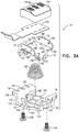
Figs. 3A and3B are respective downward-facing and upward-facing exploded view illustrations of a magnetic stripe reader module forming part of the card reader ofFig. 1 ; -
Figs. 4A and 4B are simplified pictorial illustrations of a base portion of the magnetic stripe reader module ofFigs. 2A to 3B , shown in two different orientations; -
Fig. 5 is a simplified illustration of a stage in the assembly of the magnetic stripe reader module ofFigs. 2A - 4B ; -
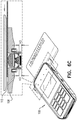
Figs. 6A ,6B and6C are simplified illustrations of the card reader ofFig. 1 in three operative orientations, when a card is not engaged with the card reader, when a card initially engages the magnetic stripe reader module and when a card is engaged in magnetic stripe card reader engagement with the card reader; and -
Fig. 7 is a simplified illustration of a card reader constructed and operative in accordance with another preferred embodiment of the present invention. - Reference is now made to
Fig. 1 , which is a simplified illustration of acard reader 100 constructed and operative in accordance with one preferred embodiment of the present invention. - As seen in
Fig. 1 , thecard reader 100 comprises a housing, preferably including atop portion 102 and abottom portion 104. Disposed within the housing, inter alia, is amain board 106 and a magnetic stripe readermodule support base 108 having anaperture 110 communicating with acard swipe slot 112. A magneticstripe reader module 114 extends partially throughaperture 110 intoslot 112. It is appreciated that throughout the description, the terms "top", "bottom", "upper", "lower" and similar terms refer to the orientations of the various elements as shown inFig. 1 , with the understanding that the orientation of thecard reader 100 and of the magnetic stripe reader module can be any suitable orientation. - Referring now additionally to
Figs. 2A - 3B , it is seen that in accordance with a preferred embodiment of the present invention, magneticstripe reader module 114 preferably comprises a magneticreader head portion 116, typically including three parallel mutually spaced magnetictrack reading sensors 118. Magneticreader head portion 116 is coupled to a flexibleflat cable 120, which operatively connects it to circuitry (not shown) preferably mounted onmain board 106. - Magnetic
reader head portion 116 and flexibleflat cable 120 are fixedly mounted onto a magnetichead mounting bracket 122. It is a particular feature of an embodiment of the present invention, that magnetichead mounting bracket 122 is spring mounted onto abase element 124 via atruncated cone spring 126. A pair ofmounting screws 128 serve to attach the magneticstripe reader module 114 onto the magnetic stripe readermodule support base 108 ataperture 110. - Magnetic
head mounting bracket 122 preferably comprises a generallyplanar portion 130 and a pair ofupstanding end portions planar portion 130 at opposite ends thereof. A pair oflegs planar portion 130 and extend therefrom in a direction opposite to that ofupstanding end portions 132.Legs reference numerals reference numerals planar portion 130 and spanrespective slots - A
retaining tab 146 extends in a plane parallel to that ofplanar portion 130 from a dependingportion 148 located at one corner of generallyplanar portion 130. A central dependingprotrusion 150 is preferably formed at a center of anunderside surface 152 of generallyplanar portion 130. Acorresponding recess 154 is preferably formed at the center of anupper surface 156 of generallyplanar portion 130. Aslot 158 is preferably formed at a junction ofplanar portion 130 andupstanding end portion 131 and preferably accommodates flexibleflat cable 120, which extends therethrough. - A pair of
spot welding locations 160 are preferably located on each ofupstanding end portions reader head portion 116 is spot welded thereto. - Reference is now made additionally to
Figs. 4A and 4B , which are simplified pictorial illustrations ofbase element 124. As seen inFigs. 1 to 4B ,base element 124 includes acentral portion 170 having a pair ofupstanding side portions corresponding mounting flanges Mounting flange 176 includes three apertures, here designated byreference numerals flange 178 includes two apertures, here designated byreference numerals Mounting flange 178 extends beyondcorresponding side portion 174 and defines a tabengagement surface portion 192. - Formed on an
upper surface 193 ofcentral portion 170 are a pair of partially circular spring seat defining portions, here designated byreference numerals upstanding side portions cylindrical protrusions corresponding protrusions cylindrical protrusions upper surface 193. - Referring now particularly to
Figs. 2C and 2D , it is appreciated that when assembled, thetruncated cone spring 126 is seated at its narrow end aboutprotrusion 150 extending downwardly fromunderside surface 152 of generallyplanar portion 130 of magnetichead mounting bracket 122 and is seated at its wide end between circular springseat defining portions upper surface 193 ofcentral portion 170 ofbase element 124. - Generally
cylindrical protrusions corresponding protrusions base element 124 are preferably located in slidable engagement with respectiveelongate slots respective legs head mounting bracket 122 for guiding and limiting mutual spring loaded displacement therebetween as described hereinbelow with respect toFigs. 6A to 6C . - Reference is now made additionally to
Fig. 5 , which is a simplified illustration of a stage in the assembly of the magnetic stripe reader module ofFigs. 2A to 4B . It is seen thattab 146 is preferably brought into engagement with tabengagement surface portion 192 ofbase element 124 just prior to arrangement ofslots head mounting bracket 122 into slidable operative engagement withprotrusions base element 124. Reference is now made toFigs. 6A ,6B and6C , which are simplified illustrations of the card reader ofFigs. 1 to 5 in three operative orientations, when a card is not engaged with thecard reader 100, when a card initially engages the magneticstripe reader module 114 and when a card is engaged in magnetic stripe card reader engagement with thecard reader 100, respectively. As seen by comparingFigs. 6A and6B , initial insertion of a payment card intoslot 112 and engagement of a leading edge of the payment card with the magneticstripe reader module 114 causes initial skewed displacement of the magneticstripe reader module 114 against the urging oftruncated cone spring 126, as seen inFig. 6B . - The displacement of the magnetic
stripe reader module 114 and compression oftruncated cone spring 126 caused by the engagement of a leading edge of the payment card with the magneticstripe reader module 114 is seen by a comparison of the distance between a lower surface ofcentral portion 170 ofbase element 124 and a lower surface offoot portions 144 ofleg 136, as indicated by H0 inFig. 6A , and the distance between the lower surface ofcentral portion 170 ofbase element 124 and the lower surface offoot portions legs Fig. 6B , respectively. As seen inFigs. 6A to 6B , H0 and H1 are equal, since the left side of the reader, as seen inFig. 6B , has not been displaced downwardly, while H2 is less than H0, since the right side of the reader, as seen inFig. 6B , has been displaced downwardly by the engagement of a leading edge of the payment card with the magneticstripe reader module 114. - Once the leading edge of the payment card passes the highest portion of the magnetic
stripe reader module 114, as seen inFig. 6C , the magneticstripe reader module 114 is further displaced against the urging oftruncated cone spring 126 and is no longer skewed but is displaced downward with respect to slot 112, as compared with its orientation in the absence of card engagement, as seen inFig. 6A . - The displacement of the magnetic
stripe reader module 114 and compression oftruncated cone spring 126 caused by the leading edge of the payment card passing the highest portion of the magneticstripe reader module 114 is seen by a comparison of the distance between a lower surface ofcentral portion 170 ofbase element 124 and a lower surface offoot portions 144 ofleg 136, as indicated by H1 inFig. 6B , and the distance between the lower surface ofcentral portion 170 ofbase element 124 and the lower surface offoot portion 144 ofleg 136, as indicated by H3 inFig. 6C . As seen inFigs. 6B to 6C , H1 is greater than H3 and H2 equals H3, since the left side of the reader, as seen inFig. 6C , has been displaced downwardly by the engagement of the payment card with the magneticstripe reader module 114 to the same extent as the right side of the reader was previously displaced. - In a preferred embodiment of the present invention,
spring 126 exerts a force of approximately 1.0N in the absence of a card inslot 112. During card swipe, when a magnetic stripe card is in operative engagement with the magneticstripe reader module 114, the force exerted byspring 126 increases to about 1.6N, due to compression ofsprings 126. - Reference is now made to
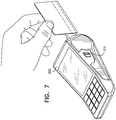
Fig. 7 , which is a simplified illustration of acard reader 300 constructed and operative in accordance with another preferred embodiment of the present invention. As distinguished fromcard reader 100 described hereinabove with reference toFigs. 1 to 6C ,card reader 300 is characterized in that it contains a sideways mounted magneticstripe reader module 314, which may in all relevant respects be identical to magneticstripe reader module 114 ofFigs. 1 to 6C .
Claims (3)
- Magnetic stripe reader comprising:- a base element (124) defining a first spring seat (194, 196);- a magnetic module support element (122) arranged for limited pivotable motion relative to the base element (124) and defining a second spring seat (150), the magnetic module support element (122) includes- - a generally planar portion (130); and- - a pair of legs (134, 136) disposed generally perpendicularly to the generally planar portion (130), wherein each of the pair of legs (134, 136) defines an elongated slot (138, 140);- a truncated conical spring (126) having a first end, seated in the first spring seat (194, 196), and a second end, seated in the second spring seat (150); wherein the truncated conical spring (126) enabling the limited pivotable motion of the magnetic module support element (122), relative to the base element (124);- and a magnetic module (116) fixedly mounted onto the magnetic module support element (122).
- Magnetic stripe reader according to claim 1, wherein the truncated conical spring (126) provides skewed displacement of the magnetic module support element (122) relative to the base element (124) when the magnetic stripe reader (114) is engaged by a leading edge of a card, preferably a payment card.
- Magnetic stripe reader according to claim 1, the first end of the truncated conical spring (126) having a relatively large diameter, seated in the first spring seat (194, 196), and the second end having a relatively small diameter, seated in the second spring seat (150).
Applications Claiming Priority (1)
| Application Number | Priority Date | Filing Date | Title |
|---|---|---|---|
| US15/014,403 US9721124B1 (en) | 2016-02-03 | 2016-02-03 | Magnetic card reader |
Publications (2)
| Publication Number | Publication Date |
|---|---|
| EP3203408A1 EP3203408A1 (en) | 2017-08-09 |
| EP3203408B1 true EP3203408B1 (en) | 2018-12-12 |
Family
ID=57965719
Family Applications (1)
| Application Number | Title | Priority Date | Filing Date |
|---|---|---|---|
| EP17154184.0A Not-in-force EP3203408B1 (en) | 2016-02-03 | 2017-02-01 | Magnetic card reader and card reading method |
Country Status (3)
| Country | Link |
|---|---|
| US (2) | US9721124B1 (en) |
| EP (1) | EP3203408B1 (en) |
| CN (1) | CN107038396B (en) |
Families Citing this family (1)
| Publication number | Priority date | Publication date | Assignee | Title |
|---|---|---|---|---|
| CN111353316B (en) * | 2020-03-11 | 2023-07-11 | 全南英创电子有限公司 | Mounting structure and mounting method of card swiping magnetic head |
Family Cites Families (37)
| Publication number | Priority date | Publication date | Assignee | Title |
|---|---|---|---|---|
| US3949193A (en) | 1974-01-07 | 1976-04-06 | Electrospace Corporation | Credit card reader having two magnetic readout heads |
| US4028734A (en) | 1975-05-19 | 1977-06-07 | American Magnetics Corporation | Plural magnetic head assembly with independently supporting structure |
| US4176259A (en) * | 1976-10-04 | 1979-11-27 | Honeywell Information Systems, Inc. | Read apparatus |
| US4184179A (en) | 1978-02-24 | 1980-01-15 | Cubic Western Data | Reproduction of binary signals from a recording medium that may be read at varying speeds |
| JPS589262A (en) | 1981-07-08 | 1983-01-19 | Nippon Denso Co Ltd | Magnetic card reader |
| JPS58122615A (en) | 1982-01-18 | 1983-07-21 | Sankyo Seiki Mfg Co Ltd | Magnetic head holding mechanism of plural channels |
| US4777551A (en) * | 1985-07-24 | 1988-10-11 | Hitachi, Ltd. | Magnetic head supporting mechanism for flexible double-sided magnetic disks |
| DE3910880A1 (en) | 1989-04-04 | 1990-10-11 | Amphenol Tuchel Elect | CARDANICAL SUSPENSION FOR MAGNETIC HEADS |
| JPH02281464A (en) | 1989-04-21 | 1990-11-19 | Nhk Spring Co Ltd | Card reader/writer |
| JPH0460910A (en) | 1990-06-26 | 1992-02-26 | Omron Corp | Magnetic head holder |
| JP3121057B2 (en) * | 1991-09-12 | 2000-12-25 | 松下電器産業株式会社 | Magnetic head support device for magnetic card reader |
| US5270523A (en) | 1992-01-30 | 1993-12-14 | Uniform Industrial Corp. | Plate spring for mounting a magnetic stripe card reader's magnetic head |
| US5463678A (en) * | 1993-03-26 | 1995-10-31 | Claircom Communications Group, Inc. | Credit card reader |
| JPH0997313A (en) | 1995-10-02 | 1997-04-08 | Nippon Conlux Co Ltd | Information recording and reproducing device |
| JPH09231325A (en) | 1996-02-28 | 1997-09-05 | Hitachi Ltd | Portable card reader |
| JPH1083529A (en) | 1996-09-10 | 1998-03-31 | Anritsu Corp | Card processor |
| US6250552B1 (en) | 1996-11-15 | 2001-06-26 | Sankyo Seiki Mfg. Co., Ltd. | Card reader having means for reducing the size of the card reader |
| US6042010A (en) | 1997-01-10 | 2000-03-28 | Matsushita Electric Industrial Co., Ltd. | Card reader and a method of installing a card reader |
| US5945654A (en) | 1998-01-28 | 1999-08-31 | Fametech Inc. | Card reader with dual-headed card slot |
| US6342982B1 (en) | 1998-08-31 | 2002-01-29 | Matsushita Electric Industrial Co., Ltd. | Card reader |
| JP2000293813A (en) | 1999-04-08 | 2000-10-20 | Sankyo Seiki Mfg Co Ltd | Multi-channel magnetic head, its production, and magnetic card reader using this magnetic head |
| JP3664644B2 (en) | 2000-10-06 | 2005-06-29 | 日立オムロンターミナルソリューションズ株式会社 | Magnetic head support structure and magnetic card reader |
| JPWO2003012781A1 (en) | 2001-07-30 | 2004-11-25 | 富士通株式会社 | Magnetic head testing equipment |
| ATE350727T1 (en) | 2001-08-24 | 2007-01-15 | Cubic Corp | UNIVERSAL TICKET TRANSPORT DEVICE |
| US6601765B2 (en) | 2001-11-13 | 2003-08-05 | Unitech Electronics Co., Ltd. | Waterproof structure for card machine |
| JP3855804B2 (en) | 2002-03-04 | 2006-12-13 | 旭精工株式会社 | Card processing device equipped with a card recovery device |
| US7347370B2 (en) | 2003-11-18 | 2008-03-25 | Magtek, Inc. | Self-aligning magnetic read head incorporating lift-up detection |
| US7268567B2 (en) | 2005-02-04 | 2007-09-11 | Research In Motion Limited | Probe assembly with multi-directional freedom of motion and mounting assembly therefor |
| US9038891B2 (en) | 2005-12-20 | 2015-05-26 | Diebold Self-Service Systems Division Of Diebold, Incorporated | Banking machine controlled responsive to data read from data bearing records |
| US7753275B2 (en) | 2007-09-17 | 2010-07-13 | Verifone, Inc. | Magnetic card reader, especially for point of sale terminals |
| JP5179924B2 (en) | 2008-03-31 | 2013-04-10 | 日本電産サンキョー株式会社 | Card reader shutter mechanism and card reader |
| WO2010137161A1 (en) * | 2009-05-29 | 2010-12-02 | 富士通フロンテック株式会社 | Magnetic card reader |
| US8931698B2 (en) | 2010-02-08 | 2015-01-13 | Nidec Sankyo Corporation | Card reader |
| US8333521B2 (en) | 2010-04-01 | 2012-12-18 | Va, Inc. | Shutter assembly with rotating magnet |
| US9613234B2 (en) * | 2012-07-19 | 2017-04-04 | BBPOS Limited | System and method for mounting a magnetic card reader head onto a card reader |
| CN203422750U (en) * | 2013-08-30 | 2014-02-05 | 北京泰和磁记录制品有限公司 | Magnetic card head and magnetic card reader |
| US9436856B2 (en) | 2014-12-23 | 2016-09-06 | Verifone, Inc. | Magnetic stripe card reader |
-
2016
- 2016-02-03 US US15/014,403 patent/US9721124B1/en not_active Expired - Fee Related
-
2017
- 2017-01-22 CN CN201710045833.3A patent/CN107038396B/en active Active
- 2017-02-01 EP EP17154184.0A patent/EP3203408B1/en not_active Not-in-force
- 2017-05-25 US US15/604,920 patent/US9971915B2/en active Active
Non-Patent Citations (1)
| Title |
|---|
| None * |
Also Published As
| Publication number | Publication date |
|---|---|
| CN107038396B (en) | 2021-11-02 |
| US20170262666A1 (en) | 2017-09-14 |
| EP3203408A1 (en) | 2017-08-09 |
| US9971915B2 (en) | 2018-05-15 |
| US20170220826A1 (en) | 2017-08-03 |
| CN107038396A (en) | 2017-08-11 |
| US9721124B1 (en) | 2017-08-01 |
Similar Documents
| Publication | Publication Date | Title |
|---|---|---|
| US6494550B1 (en) | Fixing base structure of a slide track | |
| US8070498B2 (en) | Contact and electrical connector having such contact | |
| JP5126786B2 (en) | Pad clip for disc brake device | |
| US20190181579A1 (en) | Electrical connector | |
| JP4381432B2 (en) | Double-sided connector | |
| US20150230363A1 (en) | Set top box having heat sink pressure applying means | |
| JP2000036349A (en) | Support for contact | |
| JPH031311A (en) | Cardan type supporter for magnetic head | |
| US10276976B1 (en) | Card edge connector system | |
| US7503774B2 (en) | Surface mount contact member | |
| US9748731B2 (en) | Optical apparatus | |
| US9971915B2 (en) | Magnetic card reader | |
| JP6357406B2 (en) | Card reader | |
| CN109691250A (en) | substrate holding device | |
| US20150059131A1 (en) | Fixing Structure for Rope | |
| JP5513848B2 (en) | Inductor | |
| US11060655B2 (en) | Adjustable stand for mobile devices | |
| US9436856B2 (en) | Magnetic stripe card reader | |
| US7318746B2 (en) | Card socket assembly | |
| KR102687847B1 (en) | Bobbin and transformer including the bobbin | |
| CN106066114A (en) | Domestic refrigerator including the bearing angle with plate shape supporting top | |
| JP5708002B2 (en) | socket | |
| KR100772004B1 (en) | Locking structure | |
| US6905067B2 (en) | Guide shaft for a chip card holding assembly | |
| US20170316906A1 (en) | Electromagnetic relay |
Legal Events
| Date | Code | Title | Description |
|---|---|---|---|
| PUAI | Public reference made under article 153(3) epc to a published international application that has entered the european phase |
Free format text: ORIGINAL CODE: 0009012 |
|
| STAA | Information on the status of an ep patent application or granted ep patent |
Free format text: STATUS: THE APPLICATION HAS BEEN PUBLISHED |
|
| AK | Designated contracting states |
Kind code of ref document: A1 Designated state(s): AL AT BE BG CH CY CZ DE DK EE ES FI FR GB GR HR HU IE IS IT LI LT LU LV MC MK MT NL NO PL PT RO RS SE SI SK SM TR |
|
| AX | Request for extension of the european patent |
Extension state: BA ME |
|
| STAA | Information on the status of an ep patent application or granted ep patent |
Free format text: STATUS: REQUEST FOR EXAMINATION WAS MADE |
|
| 17P | Request for examination filed |
Effective date: 20180209 |
|
| RBV | Designated contracting states (corrected) |
Designated state(s): AL AT BE BG CH CY CZ DE DK EE ES FI FR GB GR HR HU IE IS IT LI LT LU LV MC MK MT NL NO PL PT RO RS SE SI SK SM TR |
|
| GRAP | Despatch of communication of intention to grant a patent |
Free format text: ORIGINAL CODE: EPIDOSNIGR1 |
|
| STAA | Information on the status of an ep patent application or granted ep patent |
Free format text: STATUS: GRANT OF PATENT IS INTENDED |
|
| INTG | Intention to grant announced |
Effective date: 20180628 |
|
| GRAS | Grant fee paid |
Free format text: ORIGINAL CODE: EPIDOSNIGR3 |
|
| GRAA | (expected) grant |
Free format text: ORIGINAL CODE: 0009210 |
|
| STAA | Information on the status of an ep patent application or granted ep patent |
Free format text: STATUS: THE PATENT HAS BEEN GRANTED |
|
| AK | Designated contracting states |
Kind code of ref document: B1 Designated state(s): AL AT BE BG CH CY CZ DE DK EE ES FI FR GB GR HR HU IE IS IT LI LT LU LV MC MK MT NL NO PL PT RO RS SE SI SK SM TR |
|
| REG | Reference to a national code |
Ref country code: GB Ref legal event code: FG4D |
|
| REG | Reference to a national code |
Ref country code: CH Ref legal event code: EP |
|
| REG | Reference to a national code |
Ref country code: AT Ref legal event code: REF Ref document number: 1076957 Country of ref document: AT Kind code of ref document: T Effective date: 20181215 |
|
| REG | Reference to a national code |
Ref country code: DE Ref legal event code: R096 Ref document number: 602017001233 Country of ref document: DE |
|
| REG | Reference to a national code |
Ref country code: IE Ref legal event code: FG4D |
|
| REG | Reference to a national code |
Ref country code: DE Ref legal event code: R082 Ref document number: 602017001233 Country of ref document: DE Representative=s name: LEONHARD & PARTNER PATENTANWAELTE, DE |
|
| REG | Reference to a national code |
Ref country code: NL Ref legal event code: MP Effective date: 20181212 |
|
| REG | Reference to a national code |
Ref country code: LT Ref legal event code: MG4D |
|
| PG25 | Lapsed in a contracting state [announced via postgrant information from national office to epo] |
Ref country code: FI Free format text: LAPSE BECAUSE OF FAILURE TO SUBMIT A TRANSLATION OF THE DESCRIPTION OR TO PAY THE FEE WITHIN THE PRESCRIBED TIME-LIMIT Effective date: 20181212 Ref country code: BG Free format text: LAPSE BECAUSE OF FAILURE TO SUBMIT A TRANSLATION OF THE DESCRIPTION OR TO PAY THE FEE WITHIN THE PRESCRIBED TIME-LIMIT Effective date: 20190312 Ref country code: HR Free format text: LAPSE BECAUSE OF FAILURE TO SUBMIT A TRANSLATION OF THE DESCRIPTION OR TO PAY THE FEE WITHIN THE PRESCRIBED TIME-LIMIT Effective date: 20181212 Ref country code: LV Free format text: LAPSE BECAUSE OF FAILURE TO SUBMIT A TRANSLATION OF THE DESCRIPTION OR TO PAY THE FEE WITHIN THE PRESCRIBED TIME-LIMIT Effective date: 20181212 Ref country code: LT Free format text: LAPSE BECAUSE OF FAILURE TO SUBMIT A TRANSLATION OF THE DESCRIPTION OR TO PAY THE FEE WITHIN THE PRESCRIBED TIME-LIMIT Effective date: 20181212 Ref country code: NO Free format text: LAPSE BECAUSE OF FAILURE TO SUBMIT A TRANSLATION OF THE DESCRIPTION OR TO PAY THE FEE WITHIN THE PRESCRIBED TIME-LIMIT Effective date: 20190312 |
|
| REG | Reference to a national code |
Ref country code: AT Ref legal event code: MK05 Ref document number: 1076957 Country of ref document: AT Kind code of ref document: T Effective date: 20181212 |
|
| PG25 | Lapsed in a contracting state [announced via postgrant information from national office to epo] |
Ref country code: GR Free format text: LAPSE BECAUSE OF FAILURE TO SUBMIT A TRANSLATION OF THE DESCRIPTION OR TO PAY THE FEE WITHIN THE PRESCRIBED TIME-LIMIT Effective date: 20190313 Ref country code: RS Free format text: LAPSE BECAUSE OF FAILURE TO SUBMIT A TRANSLATION OF THE DESCRIPTION OR TO PAY THE FEE WITHIN THE PRESCRIBED TIME-LIMIT Effective date: 20181212 Ref country code: AL Free format text: LAPSE BECAUSE OF FAILURE TO SUBMIT A TRANSLATION OF THE DESCRIPTION OR TO PAY THE FEE WITHIN THE PRESCRIBED TIME-LIMIT Effective date: 20181212 Ref country code: SE Free format text: LAPSE BECAUSE OF FAILURE TO SUBMIT A TRANSLATION OF THE DESCRIPTION OR TO PAY THE FEE WITHIN THE PRESCRIBED TIME-LIMIT Effective date: 20181212 |
|
| PG25 | Lapsed in a contracting state [announced via postgrant information from national office to epo] |
Ref country code: NL Free format text: LAPSE BECAUSE OF FAILURE TO SUBMIT A TRANSLATION OF THE DESCRIPTION OR TO PAY THE FEE WITHIN THE PRESCRIBED TIME-LIMIT Effective date: 20181212 |
|
| PG25 | Lapsed in a contracting state [announced via postgrant information from national office to epo] |
Ref country code: IT Free format text: LAPSE BECAUSE OF FAILURE TO SUBMIT A TRANSLATION OF THE DESCRIPTION OR TO PAY THE FEE WITHIN THE PRESCRIBED TIME-LIMIT Effective date: 20181212 Ref country code: CZ Free format text: LAPSE BECAUSE OF FAILURE TO SUBMIT A TRANSLATION OF THE DESCRIPTION OR TO PAY THE FEE WITHIN THE PRESCRIBED TIME-LIMIT Effective date: 20181212 Ref country code: PT Free format text: LAPSE BECAUSE OF FAILURE TO SUBMIT A TRANSLATION OF THE DESCRIPTION OR TO PAY THE FEE WITHIN THE PRESCRIBED TIME-LIMIT Effective date: 20190412 Ref country code: ES Free format text: LAPSE BECAUSE OF FAILURE TO SUBMIT A TRANSLATION OF THE DESCRIPTION OR TO PAY THE FEE WITHIN THE PRESCRIBED TIME-LIMIT Effective date: 20181212 Ref country code: PL Free format text: LAPSE BECAUSE OF FAILURE TO SUBMIT A TRANSLATION OF THE DESCRIPTION OR TO PAY THE FEE WITHIN THE PRESCRIBED TIME-LIMIT Effective date: 20181212 |
|
| PG25 | Lapsed in a contracting state [announced via postgrant information from national office to epo] |
Ref country code: EE Free format text: LAPSE BECAUSE OF FAILURE TO SUBMIT A TRANSLATION OF THE DESCRIPTION OR TO PAY THE FEE WITHIN THE PRESCRIBED TIME-LIMIT Effective date: 20181212 Ref country code: RO Free format text: LAPSE BECAUSE OF FAILURE TO SUBMIT A TRANSLATION OF THE DESCRIPTION OR TO PAY THE FEE WITHIN THE PRESCRIBED TIME-LIMIT Effective date: 20181212 Ref country code: SK Free format text: LAPSE BECAUSE OF FAILURE TO SUBMIT A TRANSLATION OF THE DESCRIPTION OR TO PAY THE FEE WITHIN THE PRESCRIBED TIME-LIMIT Effective date: 20181212 Ref country code: SM Free format text: LAPSE BECAUSE OF FAILURE TO SUBMIT A TRANSLATION OF THE DESCRIPTION OR TO PAY THE FEE WITHIN THE PRESCRIBED TIME-LIMIT Effective date: 20181212 Ref country code: IS Free format text: LAPSE BECAUSE OF FAILURE TO SUBMIT A TRANSLATION OF THE DESCRIPTION OR TO PAY THE FEE WITHIN THE PRESCRIBED TIME-LIMIT Effective date: 20190412 |
|
| REG | Reference to a national code |
Ref country code: DE Ref legal event code: R097 Ref document number: 602017001233 Country of ref document: DE |
|
| PLBE | No opposition filed within time limit |
Free format text: ORIGINAL CODE: 0009261 |
|
| STAA | Information on the status of an ep patent application or granted ep patent |
Free format text: STATUS: NO OPPOSITION FILED WITHIN TIME LIMIT |
|
| PG25 | Lapsed in a contracting state [announced via postgrant information from national office to epo] |
Ref country code: DK Free format text: LAPSE BECAUSE OF FAILURE TO SUBMIT A TRANSLATION OF THE DESCRIPTION OR TO PAY THE FEE WITHIN THE PRESCRIBED TIME-LIMIT Effective date: 20181212 Ref country code: AT Free format text: LAPSE BECAUSE OF FAILURE TO SUBMIT A TRANSLATION OF THE DESCRIPTION OR TO PAY THE FEE WITHIN THE PRESCRIBED TIME-LIMIT Effective date: 20181212 Ref country code: MC Free format text: LAPSE BECAUSE OF FAILURE TO SUBMIT A TRANSLATION OF THE DESCRIPTION OR TO PAY THE FEE WITHIN THE PRESCRIBED TIME-LIMIT Effective date: 20181212 Ref country code: LU Free format text: LAPSE BECAUSE OF NON-PAYMENT OF DUE FEES Effective date: 20190201 Ref country code: SI Free format text: LAPSE BECAUSE OF FAILURE TO SUBMIT A TRANSLATION OF THE DESCRIPTION OR TO PAY THE FEE WITHIN THE PRESCRIBED TIME-LIMIT Effective date: 20181212 |
|
| 26N | No opposition filed |
Effective date: 20190913 |
|
| REG | Reference to a national code |
Ref country code: BE Ref legal event code: MM Effective date: 20190228 |
|
| REG | Reference to a national code |
Ref country code: IE Ref legal event code: MM4A |
|
| PG25 | Lapsed in a contracting state [announced via postgrant information from national office to epo] |
Ref country code: IE Free format text: LAPSE BECAUSE OF NON-PAYMENT OF DUE FEES Effective date: 20190201 |
|
| PG25 | Lapsed in a contracting state [announced via postgrant information from national office to epo] |
Ref country code: BE Free format text: LAPSE BECAUSE OF NON-PAYMENT OF DUE FEES Effective date: 20190228 |
|
| PG25 | Lapsed in a contracting state [announced via postgrant information from national office to epo] |
Ref country code: TR Free format text: LAPSE BECAUSE OF FAILURE TO SUBMIT A TRANSLATION OF THE DESCRIPTION OR TO PAY THE FEE WITHIN THE PRESCRIBED TIME-LIMIT Effective date: 20181212 |
|
| PG25 | Lapsed in a contracting state [announced via postgrant information from national office to epo] |
Ref country code: MT Free format text: LAPSE BECAUSE OF NON-PAYMENT OF DUE FEES Effective date: 20190201 |
|
| REG | Reference to a national code |
Ref country code: CH Ref legal event code: PL |
|
| PG25 | Lapsed in a contracting state [announced via postgrant information from national office to epo] |
Ref country code: LI Free format text: LAPSE BECAUSE OF NON-PAYMENT OF DUE FEES Effective date: 20200229 Ref country code: CH Free format text: LAPSE BECAUSE OF NON-PAYMENT OF DUE FEES Effective date: 20200229 |
|
| PG25 | Lapsed in a contracting state [announced via postgrant information from national office to epo] |
Ref country code: CY Free format text: LAPSE BECAUSE OF FAILURE TO SUBMIT A TRANSLATION OF THE DESCRIPTION OR TO PAY THE FEE WITHIN THE PRESCRIBED TIME-LIMIT Effective date: 20181212 |
|
| PG25 | Lapsed in a contracting state [announced via postgrant information from national office to epo] |
Ref country code: HU Free format text: LAPSE BECAUSE OF FAILURE TO SUBMIT A TRANSLATION OF THE DESCRIPTION OR TO PAY THE FEE WITHIN THE PRESCRIBED TIME-LIMIT; INVALID AB INITIO Effective date: 20170201 |
|
| PG25 | Lapsed in a contracting state [announced via postgrant information from national office to epo] |
Ref country code: MK Free format text: LAPSE BECAUSE OF FAILURE TO SUBMIT A TRANSLATION OF THE DESCRIPTION OR TO PAY THE FEE WITHIN THE PRESCRIBED TIME-LIMIT Effective date: 20181212 |
|
| REG | Reference to a national code |
Ref country code: DE Ref legal event code: R082 Ref document number: 602017001233 Country of ref document: DE Representative=s name: LEONHARD, REIMUND, DIPL.-ING., DE |
|
| P01 | Opt-out of the competence of the unified patent court (upc) registered |
Effective date: 20230529 |
|
| PGFP | Annual fee paid to national office [announced via postgrant information from national office to epo] |
Ref country code: GB Payment date: 20240627 Year of fee payment: 8 |
|
| PGFP | Annual fee paid to national office [announced via postgrant information from national office to epo] |
Ref country code: DE Payment date: 20240627 Year of fee payment: 8 |
|
| PGFP | Annual fee paid to national office [announced via postgrant information from national office to epo] |
Ref country code: FR Payment date: 20240625 Year of fee payment: 8 |
|
| REG | Reference to a national code |
Ref country code: DE Ref legal event code: R119 Ref document number: 602017001233 Country of ref document: DE |
|
| GBPC | Gb: european patent ceased through non-payment of renewal fee |
Effective date: 20250201 |
|
| PG25 | Lapsed in a contracting state [announced via postgrant information from national office to epo] |
Ref country code: DE Free format text: LAPSE BECAUSE OF NON-PAYMENT OF DUE FEES Effective date: 20250902 |
|
| PG25 | Lapsed in a contracting state [announced via postgrant information from national office to epo] |
Ref country code: GB Free format text: LAPSE BECAUSE OF NON-PAYMENT OF DUE FEES Effective date: 20250201 |
|
| PG25 | Lapsed in a contracting state [announced via postgrant information from national office to epo] |
Ref country code: FR Free format text: LAPSE BECAUSE OF NON-PAYMENT OF DUE FEES Effective date: 20250228 |