EP3203390A1 - Fine mask plate net stretching process analysis method - Google Patents
Fine mask plate net stretching process analysis method Download PDFInfo
- Publication number
- EP3203390A1 EP3203390A1 EP15791467.2A EP15791467A EP3203390A1 EP 3203390 A1 EP3203390 A1 EP 3203390A1 EP 15791467 A EP15791467 A EP 15791467A EP 3203390 A1 EP3203390 A1 EP 3203390A1
- Authority
- EP
- European Patent Office
- Prior art keywords
- counterforce
- metal frame
- fine mask
- mask plate
- lcf
- Prior art date
- Legal status (The legal status is an assumption and is not a legal conclusion. Google has not performed a legal analysis and makes no representation as to the accuracy of the status listed.)
- Granted
Links
Images
Classifications
-
- G—PHYSICS
- G01—MEASURING; TESTING
- G01N—INVESTIGATING OR ANALYSING MATERIALS BY DETERMINING THEIR CHEMICAL OR PHYSICAL PROPERTIES
- G01N3/00—Investigating strength properties of solid materials by application of mechanical stress
- G01N3/08—Investigating strength properties of solid materials by application of mechanical stress by applying steady tensile or compressive forces
-
- G—PHYSICS
- G06—COMPUTING OR CALCULATING; COUNTING
- G06F—ELECTRIC DIGITAL DATA PROCESSING
- G06F30/00—Computer-aided design [CAD]
- G06F30/20—Design optimisation, verification or simulation
- G06F30/23—Design optimisation, verification or simulation using finite element methods [FEM] or finite difference methods [FDM]
-
- G—PHYSICS
- G01—MEASURING; TESTING
- G01N—INVESTIGATING OR ANALYSING MATERIALS BY DETERMINING THEIR CHEMICAL OR PHYSICAL PROPERTIES
- G01N2203/00—Investigating strength properties of solid materials by application of mechanical stress
- G01N2203/02—Details not specific for a particular testing method
- G01N2203/0202—Control of the test
- G01N2203/0212—Theories, calculations
- G01N2203/0216—Finite elements
-
- G—PHYSICS
- G06—COMPUTING OR CALCULATING; COUNTING
- G06F—ELECTRIC DIGITAL DATA PROCESSING
- G06F2111/00—Details relating to CAD techniques
- G06F2111/10—Numerical modelling
Definitions
- the present invention relates to the technical field of display, in particular to an analysis method of a tensioning process of a fine mask plate.
- material of each layer in the electroluminescent light-emitting device needs to be evaporated onto an array substrate by an evaporation process. Furthermore, during the evaporation, a corresponding fine mask plate needs to be used.
- the fine mask plate will be subject to thermal expansion, thereby resulting in drooping of the fine mask plate due to its gravity and changed geometry of the fine mask plate; and as a further result, the evaporation material cannot be evaporated onto a designated position.
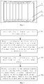
- Fig. 1 is a schematic diagram illustrating a case where a plurality of fine mask plates are welded to a metal frame.
- a plurality of strip-shaped fine mask plates 2 are welded to one metal frame 1, and then the strip-shaped fine mask plates 2 and the metal frame are used for the evaporation process together.
- the fine mask plates 2 are stretched by an appropriate force first, then an appropriate counterforce is applied to the metal frame 1 to deform the metal frame 1, and finally, the stretched highly fine mask plates 2 are welded onto the frame to which the counterforce has been applied.
- the fine mask plates 2 are tightened by welding points 3, so that the fine mask plates 2 will not droop during the evaporation.
- the preset invention provides an analysis method of a tensioning process of a fine mask plate, in order to solve the technical problem in the prior art that physical tests lead to high cost during the analysis of a tensioning process of a fine mask plate.
- an analysis method of a tensioning process of a fine mask plate including steps of: establishing a finite element model of the fine mask plate; obtaining, according to the finite element model of the fine mask plate, an optimal tensile force F1 applied to two stressed ends of the fine mask plate when the fine mask plate is in an optimal amount of deformation L1; establishing a finite element model of a metal frame for securing N fine mask plates; and obtaining, according to the optimal tensile force F1 and the finite element model of the metal frame, an actual counterforce applied to two welding sides of the metal frame before each of the fine mask plates is welded onto the metal frame.
- the actual counterforce may include a left counterforce LCF, a center counterforce CCF and a right counterforce RCF, wherein the center counterforce CCF acts on a midpoint of a welding side of the metal frame, and the left counterforce LCF and the right counterforce RCF act on positions at a quarter of the welding side, respectively.
- the step of obtaining, according to the optimal tensile force F1 and the finite element model of the metal frame, the actual counterforce applied to the two welding sides of the metal frame before each of the fine mask plates is welded onto the metal frame may include: emulating, according to the finite element model of the metal frame, a maximum amount of deformation Lmax of the metal frame when the optimal tensile force F1 is applied to every welding point on the metal frame; obtaining, according to the finite element model of the metal frame, a reference counterforce CF when only the reference counterforce CF is applied to midpoints of the two welding sides of the metal frame and when the metal frame is in the maximum amount of deformation Lmax; obtaining, according to the reference counterforce CF, a set of a left counterforce LCF_1, a center counterforce CCF_1 and a right counterforce RCF_1 all applied to the metal frame before a first fine mask plate is welded onto the metal frame, wherein the reference counterforce CF, the left counterforce LCF_1, the
- the step of emulating, according to the left counterforce LCF_1, the center counterforce CCF_1, the right counterforce RCF_1 and the finite element model of the metal frame, the left counterforce, the center counterforce and the right counterforce applied to the metal frame before each of the remaining N-1 fine mask plates is welded onto the metal frame may include: in the finite element model of the metal frame, maintaining a left counterforce LCF_i-1, a center counterforce CCF_i-1 and a right counterforce RCF_i-1 all applied to the metal frame before the (i-1) th fine mask plate is welded onto the metal frame and the optimal tensile force F1 applied to corresponding welding points of all the previous i-2 fine mask plates, and applying the optimal tensile force F1 to the welding points, corresponding to the (i-1) th fine mask plate, on the metal frame; and reducing at least one of the left counterforce LCF_i-1, the center counterforce CCF_i-1 and the right counterforce R
- the center counterforce CCF_i-1 in the process of reducing at least one of the left counterforce LCF_i-1, the center counterforce CCF_i-1 and the right counterforce RCF_i-1, the center counterforce CCF_i-1 may be reduced first, and then the left counterforce LCF_i-1 and/or the right counterforce RCF_i-1 may be reduced.
- the finite element model of the fine mask plate is a 1/4 model of the fine mask plate.
- Fig. 2 is a flowchart of an analysis method of a tensioning process of a fine mask plate provided by an embodiment of the present invention. As shown in Fig. 2 , the analysis method includes:
- Fig. 6 is a schematic diagram corresponding to step 1043 in the embodiment of the present invention.
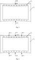
- the application of one force to a midpoint of the welding side of the metal frame 1 is replaced by application of three forces respectively to three points of the welding side (i.e., an actual counter force); and the three forces are a left counterforce LCF, a center counterforce CCF and a right counterforce RCF, respectively, wherein the center counterforce CCF acts on the midpoint of the welding side of the metal frame 1, and the left counterforce LCF and the right counterforce RCF act on positions at a quarter of the welding side of the metal frame 1, respectively.
- the reference counterforce CF, the left counterforce LCF_1, the center counterforce CCF_1 and the right counterforce RCF_1 meet the following conditions:
- the sum of the left counterforce LCF_1, the center counterforce CCF_1 and the right counterforce RCF_1 is greater than the reference counterforce CF, i.e., LCF _1 + CCF_ 1 + RCF_ 1 ⁇ CF.
- center counterforce CCF_1 is three to four times the value of the left counterforce LCF_1 (or the right counterforce RCF_1), i.e., 3* LCF _1 ⁇ CCF _1 ⁇ 4 *LCF _1 .
- step 1041 and step 1042 a set of a left counterforce LCF_1, a center counterforce CCF_1 and a right counterforce RCF_1 applied to the metal frame 1 before the first fine mask plate is welded onto the metal frame 1 can be emulated.
- Step 1044 According to the left counterforce LCF_1, the center counterforce CCF_1, the right counterforce RCF_1 and the finite element model of the metal frame, a left counterforce, a center counterforce and a right counterforce applied to the metal frame before each of the remaining N-1 fine mask plates is welded onto the metal frame are emulated.
- Step 1044 includes;
- step 10441 and step 10442 will be described below in detail with reference to the accompanying drawings.
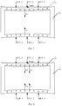
- Fig. 7 is a schematic diagram of emulating stress condition of a finite element model of a metal frame before a second fine mask plate is welded onto the metal frame.
- the left counterforce LCF_1, the center counterforce CCF_1 and the right counterforce RCF_1 applied to the metal frame 1 before the first fine mask plate is welded onto the metal frame 1 are maintained, and the optimal tensile force F1 is applied to the welding points 3, corresponding the first fine mask plate, on the metal frame 1 (in order to emulate a case where the first fine mask plate has been welded onto the metal frame).
- the amount of deformation of the finite element model of the metal frame 1 is inevitably greater than the maximum amount of deformation Lmax. Then, at least one of the left counterforce LCF_1, the center counterforce CCF_1 and the right counterforce RCF_1 is reduced until the finite element model of the metal frame 1 gets back to the maximum amount of deformation Lmax.
- the current three counterforces are a left counterforce LCF_2, a center counterforce CCF_2 and a right counterforce RCF_2, respectively. That is, a corresponding left counterforce LCF_2, a center counterforce CCF_2 and a right counterforce RCF_2, applied to the metal frame 1 before the second fine mask plate is welded onto the metal frame 1, are emulated.
- Fig. 8 is a schematic diagram of emulating stress condition of a finite element model of a metal frame before a third fine mask plate is welded onto the metal frame.
- the left counterforce LCF_2, the center counterforce CCF_2 and the right counterforce RCF_2 applied to the metal frame 1 before the second fine mask plate is welded onto the metal frame 1 are maintained;
- the optimal tensile force F1 applied to the welding points 3 corresponding to the first fine mask plate is maintained (in order to emulate a case where the first fine mask plate has been welded onto the metal frame);
- the optimal tensile force F1 is applied to the welding points 3, corresponding to the second fine mask plate, on the metal frame 1 (in order to emulate a case where the second fine mask plate has been welded onto the metal frame).
- the amount of deformation of the finite element model of the metal frame 1 is inevitably greater than the maximum amount of deformation Lmax. Then, at least one of the left counterforce LCF_2, the center counterforce CCF_2 and the right counterforce RCF_2 is reduced until the finite element model of the metal frame 1 gets back to the maximum amount of deformation Lmax.
- the current three counterforces are a left counterforce LCF_3, a center counterforce CCF_3 and a right counterforce RCF_3, respectively. That is, a corresponding left counterforce LCF_3, a center counterforce CCF_3 and a right counterforce RCF_3, applied to the metal frame 1 before the third fine mask plate is welded onto the metal frame 1, are emulated.
- the finite element model of the metal frame 1 is in the maximum amount of deformation Lmax.
- N groups of different actual counterforces including: the left counterforces, the center counterforces and the right counterforces may be obtained through the above emulation process.
- the finite element model of the fine mask plate, the finite element model of the metal frame and the actual counterforce applied to the metal frame before each of the fine mask plates obtained in the above step 104 is melded onto the metal frame may be all input into the ANSYS software through an APDL command stream, in order to emulate the welding process of each of the fine mask plates.
- the embodiment of the present invention provides an analysis method of a tensioning process of a fine mask plate.
- the analysis method based on the simulation function of the ANSYS software, finds an appropriate tensile force for stretching a fine mask plate and a corresponding actual counterforce applied to a metal frame before each fine mask plate is welded onto the metal frame through establishing a finite element model of the fine mask plate and a finite element model of the metal frame.
- the analysis process requires no physical tests, thereby effectively avoiding damaging the fine mask plate and further effectively saving the test cost.
Landscapes
- Engineering & Computer Science (AREA)
- Physics & Mathematics (AREA)
- Theoretical Computer Science (AREA)
- General Physics & Mathematics (AREA)
- Computer Hardware Design (AREA)
- Evolutionary Computation (AREA)
- Geometry (AREA)
- General Engineering & Computer Science (AREA)
- Health & Medical Sciences (AREA)
- Life Sciences & Earth Sciences (AREA)
- Chemical & Material Sciences (AREA)
- Analytical Chemistry (AREA)
- Biochemistry (AREA)
- General Health & Medical Sciences (AREA)
- Immunology (AREA)
- Pathology (AREA)
- Electroluminescent Light Sources (AREA)
- Electric Connection Of Electric Components To Printed Circuits (AREA)
- Resistance Welding (AREA)
Abstract
Description
- The present invention relates to the technical field of display, in particular to an analysis method of a tensioning process of a fine mask plate.
- In manufacturing an electroluminescent light-emitting device, material of each layer in the electroluminescent light-emitting device needs to be evaporated onto an array substrate by an evaporation process. Furthermore, during the evaporation, a corresponding fine mask plate needs to be used.
- However, due to the occurrence of high temperature during the evaporation, the fine mask plate will be subject to thermal expansion, thereby resulting in drooping of the fine mask plate due to its gravity and changed geometry of the fine mask plate; and as a further result, the evaporation material cannot be evaporated onto a designated position.
-
Fig. 1 is a schematic diagram illustrating a case where a plurality of fine mask plates are welded to a metal frame. As shown inFig. 1 , in order to solve the problem described above, in the prior art, a plurality of strip-shapedfine mask plates 2 are welded to onemetal frame 1, and then the strip-shapedfine mask plates 2 and the metal frame are used for the evaporation process together. Specifically, thefine mask plates 2 are stretched by an appropriate force first, then an appropriate counterforce is applied to themetal frame 1 to deform themetal frame 1, and finally, the stretched highlyfine mask plates 2 are welded onto the frame to which the counterforce has been applied. By using a restoring force resulted from the deformation of themetal frame 1, thefine mask plates 2 are tightened bywelding points 3, so that thefine mask plates 2 will not droop during the evaporation. - At present, in order to find an appropriate tensile force for stretching a fine mask plate and a counterforce for deforming the metal frame, physical tests are generally needed. However, during the physical tests, the fine mask plate may be damaged easily due to fine openings and small thickness thereof, and meanwhile, the fine mask plate is high in manufacturing cost, which directly increase the overall cost during the physical tests.
- The preset invention provides an analysis method of a tensioning process of a fine mask plate, in order to solve the technical problem in the prior art that physical tests lead to high cost during the analysis of a tensioning process of a fine mask plate.
- According to one aspect of the present invention, there is provided an analysis method of a tensioning process of a fine mask plate, including steps of: establishing a finite element model of the fine mask plate; obtaining, according to the finite element model of the fine mask plate, an optimal tensile force F1 applied to two stressed ends of the fine mask plate when the fine mask plate is in an optimal amount of deformation L1; establishing a finite element model of a metal frame for securing N fine mask plates; and obtaining, according to the optimal tensile force F1 and the finite element model of the metal frame, an actual counterforce applied to two welding sides of the metal frame before each of the fine mask plates is welded onto the metal frame.
- According to an embodiment of the present invention, the step of obtaining, according to the finite element model of the fine mask plate, the optimal tensile force F1 applied to the two stressed ends of the fine mask plate when the fine mask plate is in the optimal amount of deformation L1 may include: emulating, according to the finite element model of the fine mask plate, an amount of test tensile deformation L2 of the fine mask plate when the tensile force applied to the two stressed ends of the fine mask plate is a test tensile force F2; and calculating, according to the test tensile force F2 and the amount of test tensile deformation L2, the optimal tensile force F1 applied to the two stressed ends of the fine mask plate when the fine mask plate is in the optimal amount of deformation L1, wherein

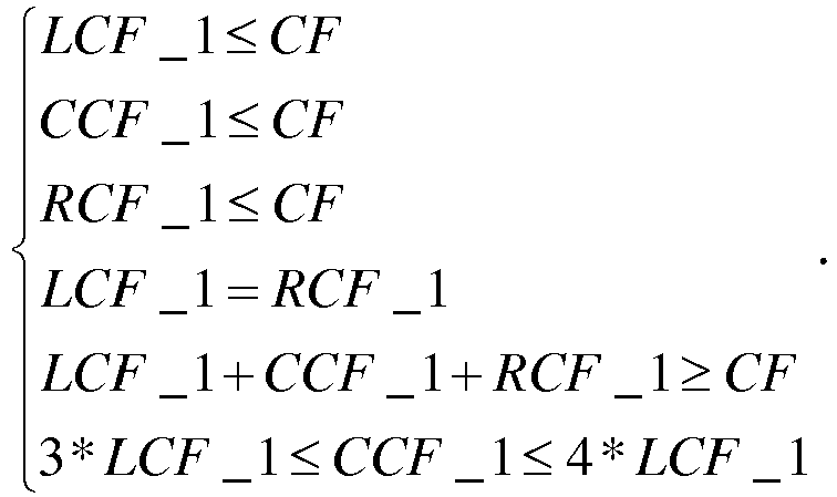
- According to an embodiment of the present invention, the actual counterforce may include a left counterforce LCF, a center counterforce CCF and a right counterforce RCF, wherein the center counterforce CCF acts on a midpoint of a welding side of the metal frame, and the left counterforce LCF and the right counterforce RCF act on positions at a quarter of the welding side, respectively. The step of obtaining, according to the optimal tensile force F1 and the finite element model of the metal frame, the actual counterforce applied to the two welding sides of the metal frame before each of the fine mask plates is welded onto the metal frame may include: emulating, according to the finite element model of the metal frame, a maximum amount of deformation Lmax of the metal frame when the optimal tensile force F1 is applied to every welding point on the metal frame; obtaining, according to the finite element model of the metal frame, a reference counterforce CF when only the reference counterforce CF is applied to midpoints of the two welding sides of the metal frame and when the metal frame is in the maximum amount of deformation Lmax; obtaining, according to the reference counterforce CF, a set of a left counterforce LCF_1, a center counterforce CCF_1 and a right counterforce RCF_1 all applied to the metal frame before a first fine mask plate is welded onto the metal frame, wherein the reference counterforce CF, the left counterforce LCF_1, the center counterforce CCF_1 and the right counterforce RCF_1 meet the following conditions:

emulating, according to the left counterforce LCF_1, the center counterforce CCF_1, the right counterforce RCF_1 and the finite element model of the metal frame, a left counterforce, a center counterforce and a right counterforce applied to the metal frame before each of the remaining N-1 fine mask plates is welded onto the metal frame. - According to an embodiment of the present invention, the step of emulating, according to the left counterforce LCF_1, the center counterforce CCF_1, the right counterforce RCF_1 and the finite element model of the metal frame, the left counterforce, the center counterforce and the right counterforce applied to the metal frame before each of the remaining N-1 fine mask plates is welded onto the metal frame may include: in the finite element model of the metal frame, maintaining a left counterforce LCF_i-1, a center counterforce CCF_i-1 and a right counterforce RCF_i-1 all applied to the metal frame before the (i-1)th fine mask plate is welded onto the metal frame and the optimal tensile force F1 applied to corresponding welding points of all the previous i-2 fine mask plates, and applying the optimal tensile force F1 to the welding points, corresponding to the (i-1)th fine mask plate, on the metal frame; and reducing at least one of the left counterforce LCF_i-1, the center counterforce CCF_i-1 and the right counterforce RCF_i-1 until the finite element model of the metal frame is in the maximum amount of deformation Lmax, to obtain a corresponding left counterforce LCF_i, center counterforce CCF_i, and right counterforce RCF_i applied to the metal frame before the ith fine mask plate is welded onto the metal frame, wherein 2≤i≤N.
- According to an embodiment of the present invention, in the process of reducing at least one of the left counterforce LCF_i-1, the center counterforce CCF_i-1 and the right counterforce RCF_i-1, the center counterforce CCF_i-1 may be reduced first, and then the left counterforce LCF_i-1 and/or the right counterforce RCF_i-1 may be reduced.
- According to an embodiment of the present invention, the step of obtaining, according to the finite element model of the metal frame, the reference counterforce CF when only the reference counterforce CF is applied to the midpoints of the two welding sides of the metal frame and when the metal frame is in the maximum amount of deformation Lmax may include: emulating, according to the finite element model of the metal frame, an amount of test compressive deformation TL of the metal frame when a test counterforce TCF is applied only to the midpoints of the two welding sides of the metal frame; and calculating, according to the test counterforce TCF and the amount of test compressive deformation TL, the reference counterforce CF applied to the midpoints of the two welding sides of the metal frame when the metal frame is in the maximum amount of deformation Lmax, wherein

- According to an embodiment of the present invention, the finite element model of the fine mask plate is a 1/4 model of the fine mask plate.
- The present invention has the following beneficial effects:
- The present invention provides an analysis method of a tensioning process of a fine mask plate. The analysis method, based on the simulation function of ANSYS software, finds an appropriate tensile force for stretching a fine mask plate and a corresponding actual counterforce applied to a metal frame before each fine mask plate is welded onto the metal frame through establishing a finite element model of the fine mask plate and a finite element model of the metal frame. The analysis process requires no physical tests, thereby effectively avoiding damaging the fine mask plate and further effectively saving the test cost.
-
-
Fig. 1 is a schematic diagram illustrating a case where a plurality of fine mask plates are welded to a metal frame; -
Fig. 2 is a flowchart of an analysis method of a tensioning process of a fine mask plate provided by an embodiment of the present invention; -
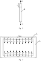
Fig. 3 is a schematic diagram corresponding to step 1021 in the embodiment of the present invention; -
Fig. 4 is a schematic diagram corresponding to step 1041 in the embodiment of the present invention; -
Fig. 5 is a schematic diagram corresponding to step 10421 in the embodiment of the present invention; -
Fig. 6 is a schematic diagram corresponding to step 1043 in the embodiment of the present invention; -
Fig. 7 is a schematic diagram of emulating stress condition of a finite element model of a metal frame before a second fine mask plate is welded onto the metal frame; and -
Fig. 8 is a schematic diagram of emulating stress condition of a finite element model of a metal frame before a third fine mask plate is welded onto the metal frame. - In order to make those skilled in the art understand the technical solution of the present invention better, an analysis method of a tensioning process of a fine mask plate provided by the present invention will be described below in detail with reference to the accompanying drawings.
-
Fig. 2 is a flowchart of an analysis method of a tensioning process of a fine mask plate provided by an embodiment of the present invention. As shown inFig. 2 , the analysis method includes: - Step 101: A finite element model of a fine mask plate is established.
Instep 101, a corresponding APDL command stream is written according to the specification and dimension of the fine mask plate and this APDL command stream is run in ANSYS software to establish a finite element model of a fine mask plate. Specifically, based on the symmetry of the fine mask plate and the computation speed of the ANSYS system, a 1/4 model of the fine mask plate may be established through a pre-processing module in the ANSYS system and then mesh-divided, and corresponding boundary conditions are applied. - Step 102: According to the finite element model of the fine mask plate, an optimal tensile force F1 applied to two stressed ends of the fine mask plate when the fine mask plate is in an optimal amount of deformation L1 is obtained.
Step 102 includes:- Step 1021: According to the finite element model of the fine mask plate, an amount of test tensile deformation L2 of the fine mask plate when the tensile force applied to the two stressed ends of the fine mask plate is a test tensile force F2 is emulated.
Fig. 3 is a schematic diagram corresponding to step 1021 in the embodiment of the present invention. As shown inFig. 3 , in step 1021, first, the test tensile force F2 is applied to the finite element model of thefine mask plate 2, and calculation is performed by a solver in the ANSYS software. Then, after the emulation process is finished, the test tensile deformation L2 of the finite element model of thefine mask plate 2 is obtained from a post-processing module of the ANSYS software. - Step 1022: According to the test tensile force F2 and the amount of test tensile deformation L2, the optimal tensile force F1 applied to the two stressed ends of the fine mask plate when the fine mask plate is in the optimal amount of deformation L1 is calculated, wherein
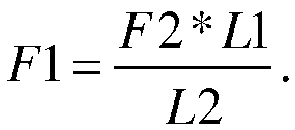
In step 1022, first, from preliminary experimental tests, it may be known that an amount of deformation of the fine mask plate during the evaporation process is the optimal amount of deformation L1. Then, based on the principle that the elastic modulus of the fine mask plate is constant, it can be concluded that

- Step 1021: According to the finite element model of the fine mask plate, an amount of test tensile deformation L2 of the fine mask plate when the tensile force applied to the two stressed ends of the fine mask plate is a test tensile force F2 is emulated.
- Step 103: A finite element model of a metal frame for securing N fine mask plates is established.
Instep 103, a corresponding APDL command stream is written according to the specification and dimension of the metal frame and this APDL command stream is run in the ANSYS software to establish a finite element model of the metal frame; and this finite element model is then mesh-divided, and corresponding boundary conditions are applied. - Step 104: According to the optimal tensile force F1 and the finite element model of the metal frame, an actual counterforce applied to two welding sides of the metal frame before each of the fine mask plates is welded onto the metal frame is obtained.
Step 104 includes:- Step 1041: According to the finite element model of the metal frame, a maximum amount of deformation Lmax of the metal frame when the optimal tensile force F1 is applied to every welding point on the metal frame is emulated.
Fig. 4 is a schematic diagram corresponding to step 1041 in the embodiment of the present invention. As shown inFig. 4 , in step 1041, first, the optimal tensile force F1 is applied to everycorresponding welding point 3 in the finite element model of themetal frame 1 and calculation is performed by a solver in the ANSYS software. Then, after emulation process is finished, the maximum amount of deformation Lmax of the finite element model of themetal frame 1 is obtained from a post-processing module of the ANSYS software. It needs to be noted that this process is used for emulating the deformation of the metal frame when all of the N fine mask plates are welded onto the metal frame. - Step 1042: According to the finite element model of the metal frame, a reference counterforce CF when the reference counterforce CF is applied only to the midpoints of two welding sides of the metal frame and the metal frame is in the maximum amount of deformation Lmax is obtained.
Optionally, step 1042 includes:- Step 10421: According to the finite element model of the metal frame, an amount of test compressive deformation TL of the metal frame when a test counterforce TCF is applied only to the midpoints of the two welding sides of the metal frame is emulated;
Fig. 5 is a schematic diagram corresponding to step 10421 in the embodiment of the present invention. As shown inFig. 5 , in step 10421, the amount of test compressive deformation TL of the finite element model of themetal frame 1 when the test counterforce TCF is applied only to the midpoints of the two welding sides of the finite element model of themetal frame 1 is emulated. The emulation process for obtaining the test compressive deformation TL is similar to that for obtaining the maximum amount of deformation Lmax, and is not repeated redundantly here. - Step 10422: According to the test counterforce TCF and the amount of test compressive deformation TL, the reference counterforce CF applied to the midpoints of the two welding sides of the metal frame when the metal frame is in the maximum amount of deformation Lmax is calculated, wherein

In step 10422, based on the principle that the elastic modulus of the metal frame is constant, it can be concluded that

- Step 10421: According to the finite element model of the metal frame, an amount of test compressive deformation TL of the metal frame when a test counterforce TCF is applied only to the midpoints of the two welding sides of the metal frame is emulated;
- Step 1043: According to the reference counterforce CF, a set of a left counterforce LCF_1, a center counterforce CCF_1 and a right counterforce RCF_1 all applied to the metal frame before a first fine mask plate is welded onto the metal frame is obtained, wherein the reference counterforce CF, the left counterforce LCF_1, the center counterforce CCF_1 and the right counterforce RCF_1 meet the following conditions:
- Step 1041: According to the finite element model of the metal frame, a maximum amount of deformation Lmax of the metal frame when the optimal tensile force F1 is applied to every welding point on the metal frame is emulated.
-
Fig. 6 is a schematic diagram corresponding to step 1043 in the embodiment of the present invention. As shown inFig. 6 , in order to ensure the uniformity of deformation of the metal frame, for the existing tensioning equipment, the application of one force to a midpoint of the welding side of themetal frame 1 is replaced by application of three forces respectively to three points of the welding side (i.e., an actual counter force); and the three forces are a left counterforce LCF, a center counterforce CCF and a right counterforce RCF, respectively, wherein the center counterforce CCF acts on the midpoint of the welding side of themetal frame 1, and the left counterforce LCF and the right counterforce RCF act on positions at a quarter of the welding side of themetal frame 1, respectively. - In this embodiment, the reference counterforce CF, the left counterforce LCF_1, the center counterforce CCF_1 and the right counterforce RCF_1 meet the following conditions:
- the left counterforce LCF_1, the center counterforce CCF_1 and the right counterforce RCF_1 are all smaller than the reference counterforce CF, i.e., LCF_1≤CF, CCF_1≤CF, and RCF_1≤CF.
- In addition, in order to ensure that the
metal frame 1 is stressed uniformly, before a first mask plate is welded onto themetal frame 1, the left counterforce LCF_1 is equal to the right counterforce RCF_1, i.e., LCF_1=RCF_1. - Meanwhile, the sum of the left counterforce LCF_1, the center counterforce CCF_1 and the right counterforce RCF_1 is greater than the reference counterforce CF, i.e., LCF_1 + CCF_1 + RCF_1 ≥ CF.
- Finally, the center counterforce CCF_1 is three to four times the value of the left counterforce LCF_1 (or the right counterforce RCF_1), i.e., 3*LCF_1 ≤ CCF_1 ≤ 4*LCF_1.
- When all the above conditions are met, numerous groups of solutions may be obtained according to the reference counterforce CF. In this embodiment, it only needs to pick any one group of solutions among the numerous groups of solutions for emulating.
- With the above step 1041 and step 1042, a set of a left counterforce LCF_1, a center counterforce CCF_1 and a right counterforce RCF_1 applied to the
metal frame 1 before the first fine mask plate is welded onto themetal frame 1 can be emulated. - Step 1044: According to the left counterforce LCF_1, the center counterforce CCF_1, the right counterforce RCF_1 and the finite element model of the metal frame, a left counterforce, a center counterforce and a right counterforce applied to the metal frame before each of the remaining N-1 fine mask plates is welded onto the metal frame are emulated.
- Step 1044 includes;
- Step 10441: In the finite element model of the metal frame, a left counterforce LCF_i-1, a center counterforce CCF_i-1, a right counterforce RCF_i-1 applied to the metal frame before the (i-1)th fine mask plate is welded onto the metal frame and a corresponding optimal tensile force F1 applied to welding points of all the previous i-2 fine mask plates are maintained, and the optimal tensile force F1 is applied to welding points, corresponding to the (i-1)th fine mask plate, on the metal frame.
- Step 10442: At least one of the left counterforce LCF_i-1, the center counterforce CCF_i-1 and the right counterforce RCF_i-1 is reduced until the finite element model of the metal frame is in the maximum amount of deformation Lmax, to obtain a left counterforce LCF_i, a center counterforce CCF_i, and a right counterforce RCF_i applied to the metal frame before the ith fine mask plate is welded onto the metal frame, wherein 2≤i≤N.
- Taking that a left counterforce, a center counterforce and a right counterforce applied to the metal frame before a second and a third fine mask plate are welded onto the metal frame are emulated as an example, step 10441 and step 10442 will be described below in detail with reference to the accompanying drawings.
-
Fig. 7 is a schematic diagram of emulating stress condition of a finite element model of a metal frame before a second fine mask plate is welded onto the metal frame. As shown inFig. 7 , first, in the finite element model of themetal frame 1, the left counterforce LCF_1, the center counterforce CCF_1 and the right counterforce RCF_1 applied to themetal frame 1 before the first fine mask plate is welded onto themetal frame 1 are maintained, and the optimal tensile force F1 is applied to the welding points 3, corresponding the first fine mask plate, on the metal frame 1 (in order to emulate a case where the first fine mask plate has been welded onto the metal frame). At this moment, the amount of deformation of the finite element model of themetal frame 1 is inevitably greater than the maximum amount of deformation Lmax. Then, at least one of the left counterforce LCF_1, the center counterforce CCF_1 and the right counterforce RCF_1 is reduced until the finite element model of themetal frame 1 gets back to the maximum amount of deformation Lmax. At this moment, it can be known from the ANSYS software that the current three counterforces are a left counterforce LCF_2, a center counterforce CCF_2 and a right counterforce RCF_2, respectively. That is, a corresponding left counterforce LCF_2, a center counterforce CCF_2 and a right counterforce RCF_2, applied to themetal frame 1 before the second fine mask plate is welded onto themetal frame 1, are emulated. - The process for emulating the left counterforce, the center counterforce and the right counterforce applied to the
metal frame 1 before the second fine mask plate is welded onto themetal frame 1 is finished. -
Fig. 8 is a schematic diagram of emulating stress condition of a finite element model of a metal frame before a third fine mask plate is welded onto the metal frame. As shown inFig. 8 , first, in the finite element model of themetal frame 1, the left counterforce LCF_2, the center counterforce CCF_2 and the right counterforce RCF_2 applied to themetal frame 1 before the second fine mask plate is welded onto themetal frame 1 are maintained; the optimal tensile force F1 applied to the welding points 3 corresponding to the first fine mask plate is maintained (in order to emulate a case where the first fine mask plate has been welded onto the metal frame); and the optimal tensile force F1 is applied to the welding points 3, corresponding to the second fine mask plate, on the metal frame 1 (in order to emulate a case where the second fine mask plate has been welded onto the metal frame). At this moment, the amount of deformation of the finite element model of themetal frame 1 is inevitably greater than the maximum amount of deformation Lmax. Then, at least one of the left counterforce LCF_2, the center counterforce CCF_2 and the right counterforce RCF_2 is reduced until the finite element model of themetal frame 1 gets back to the maximum amount of deformation Lmax. At this moment, it can be known from the ANSYS software that the current three counterforces are a left counterforce LCF_3, a center counterforce CCF_3 and a right counterforce RCF_3, respectively. That is, a corresponding left counterforce LCF_3, a center counterforce CCF_3 and a right counterforce RCF_3, applied to themetal frame 1 before the third fine mask plate is welded onto themetal frame 1, are emulated. - The process for emulating the left counterforce, the center counterforce and the right counterforce applied to the
metal frame 1 before the third fine mask plate is welded onto themetal frame 1 is finished. - The above emulation process is repeated until a corresponding left counterforce LCF_N, a center counterforce CCF_N and a right counterforce RCF_N, applied to the
metal frame 1 before the Nth fine mask plate is welded onto themetal frame 1, are obtained. - It should be noted that in the above emulation process, when the fine mask plates are welded one by one, symmetrically welding from the middle of the
metal frame 1 to both sides thereof is usually employed. Hence, in emulating a left counterforce, a center counterforce and a right counterforce applied to themetal frame 1 before each of the remaining N-1 fine mask plates is welded onto themetal frame 1, the center counterforce CCF is usually reduced first, then the left counterforce LCF and/or the right counterforce RCF are/is reduced. When the optimal tensile force F1 is applied to everycorresponding welding point 3 in the finite element model of the metal frame 1 (a case where all the N fine mask plates have been welded onto the metal frame is emulated), and the left counterforce, the center counterforce and the right counterforce all have a value of 0, the finite element model of themetal frame 1 is in the maximum amount of deformation Lmax. The entire emulation process is finished, and N groups of different actual counterforces (including: the left counterforces, the center counterforces and the right counterforces) may be obtained through the above emulation process. - In order to show a continuous tensioning process better, the finite element model of the fine mask plate, the finite element model of the metal frame and the actual counterforce applied to the metal frame before each of the fine mask plates obtained in the
above step 104 is melded onto the metal frame, may be all input into the ANSYS software through an APDL command stream, in order to emulate the welding process of each of the fine mask plates. - The embodiment of the present invention provides an analysis method of a tensioning process of a fine mask plate. The analysis method, based on the simulation function of the ANSYS software, finds an appropriate tensile force for stretching a fine mask plate and a corresponding actual counterforce applied to a metal frame before each fine mask plate is welded onto the metal frame through establishing a finite element model of the fine mask plate and a finite element model of the metal frame. The analysis process requires no physical tests, thereby effectively avoiding damaging the fine mask plate and further effectively saving the test cost.
- It may be understood that, the above implementations are exemplary implementations merely used to describe the principle of the present invention, and the present invention is not limited thereto. For a person of ordinary skill in the art, various variations and improvements may be made without departing from the spirit and essence of the present invention, and those variations and improvements should also be regarded as falling into the protection scope of the present invention.
Claims (7)
- An analysis method of a tensioning process of a fine mask plate, comprising steps of:establishing a finite element model of the fine mask plate;obtaining, according to the finite element model of the fine mask plate, an optimal tensile force F1 applied to two stressed ends of the fine mask plate when the fine mask plate is in an optimal amount of deformation L1;establishing a finite element model of a metal frame for securing N fine mask plates; andobtaining, according to the optimal tensile force F1 and the finite element model of the metal frame, an actual counterforce applied to two welding sides of the metal frame before each of the fine mask plates is welded onto the metal frame.
- The analysis method of a tensioning process of a fine mask plate according to claim 1, wherein the step of obtaining, according to the finite element model of the fine mask plate, the optimal tensile force F1 applied to the two stressed ends of the fine mask plate when the fine mask plate is in the optimal amount of deformation L1 comprises:emulating, according to the finite element model of the fine mask plate, an amount of test tensile deformation L2 of the fine mask plate when the tensile force applied to the two stressed ends of the fine mask plate is a test tensile force F2; andcalculating, according to the test tensile force F2 and the amount of test tensile deformation L2, the optimal tensile force F1 applied to the two stressed ends of the fine mask plate when the fine mask plate is in the optimal amount of deformation L1, wherein

- The analysis method of a tensioning process of a fine mask plate according to claim 1, wherein the actual counterforce comprises a left counterforce LCF, a center counterforce CCF and a right counterforce RCF, wherein the center counterforce CCF acts on a midpoint of a welding side of the metal frame, and the left counterforce LCF and the right counterforce RCF act on positions at a quarter of the welding side, respectively, and
the step of obtaining, according to the optimal tensile force F1 and the finite element model of the metal frame, the actual counterforce applied to the two welding sides of the metal frame before each of the fine mask plates is welded onto the metal frame comprises:emulating, according to the finite element model of the metal frame, a maximum amount of deformation Lmax of the metal frame when the optimal tensile force F1 is applied to every welding point on the metal frame;obtaining, according to the finite element model of the metal frame, a reference counterforce CF when only the reference counterforce CF is applied to the midpoints of the two welding sides of the metal frame and when the metal frame is in the maximum amount of deformation Lmax;obtaining, according to the reference counterforce CF, a set of a left counterforce LCF_1, a center counterforce CCF_1 and a right counterforce RCF_1 all applied to the metal frame before a first fine mask plate is welded onto the metal frame, wherein the reference counterforce CF, the left counterforce LCF_1, the center counterforce CCF_1 and the right counterforce RCF_1 meet the following conditions: emulating, according to the left counterforce LCF_1, the center counterforce CCF_1, the right counterforce RCF_1 and the finite element model of the metal frame, a left counterforce, a center counterforce and a right counterforce applied to the metal frame before each of the remaining N-1 fine mask plates is welded onto the metal frame.
 - The analysis method of a tensioning process of a fine mask plate according to claim 3, wherein the step of emulating, according to the left counterforce LCF_1, the center counterforce CCF_1, the right counterforce RCF_1 and the finite element model of the metal frame, the left counterforce, the center counterforce and the right counterforce applied to the metal frame before each of the remaining N-1 fine mask plates is welded onto the metal frame comprises:in the finite element model of the metal frame, maintaining a left counterforce LCF_i-1, a center counterforce CCF_i-1 and a right counterforce RCF_i-1 all applied to the metal frame before the (i-1)th fine mask plate is welded onto the metal frame and the optimal tensile force F1 applied to corresponding welding points of all the previous i-2 fine mask plates, and applying the optimal tensile force F1 to the welding points, corresponding to the (i-1)th fine mask plate, on the metal frame; andreducing at least one of the left counterforce LCF_i-1, the center counterforce CCF_i-1 and the right counterforce RCF_i-1 until the finite element model of the metal frame is in the maximum amount of deformation Lmax, to obtain a left counterforce LCF_i, a center counterforce CCF_i, and a right counterforce RCF_i applied to the metal frame before the ith fine mask plate is welded onto the metal frame, wherein 2≤i≤N.
- The analysis method of a tensioning process of a fine mask plate according to claim 4, wherein in the process of reducing at least one of the left counterforce LCF_i-1, the center counterforce CCF_i-1 and the right counterforce RCF_i-1, the center counterforce CCF_i-1 is reduced first, then the left counterforce LCF_i-1 and/or the right counterforce RCF_i-1 are/is reduced.
- The analysis method of a tensioning process of a fine mask plate according to claim 3, wherein the step of obtaining, according to the finite element model of the metal frame, the reference counterforce CF when only the reference counterforce CF is applied to the midpoints of the two welding sides of the metal frame and when the metal frame is in the maximum amount of deformation Lmax comprises:emulating, according to the finite element model of the metal frame, an amount of test compressive deformation TL of the metal frame when a test counterforce TCF is applied to the two welding sides of the metal frame; andcalculating, according to the test counterforce TCF and the amount of test compressive deformation TL, the reference counterforce CF applied to the two welding sides of the metal frame when the metal frame is in the maximum amount of deformation Lmax, wherein

- The analysis method of a tensioning process of a fine mask plate according to claim 1, wherein the finite element model of the fine mask plate is a 1/4 model of the fine mask plate.
Applications Claiming Priority (2)
| Application Number | Priority Date | Filing Date | Title |
|---|---|---|---|
| CN201410515610.5A CN104281747B (en) | 2014-09-29 | 2014-09-29 | A kind of fine mask plate is thrown the net process analysis method |
| PCT/CN2015/070874 WO2016050013A1 (en) | 2014-09-29 | 2015-01-16 | Fine mask plate net stretching process analysis method |
Publications (3)
| Publication Number | Publication Date |
|---|---|
| EP3203390A1 true EP3203390A1 (en) | 2017-08-09 |
| EP3203390A4 EP3203390A4 (en) | 2018-05-02 |
| EP3203390B1 EP3203390B1 (en) | 2023-07-26 |
Family
ID=52256617
Family Applications (1)
| Application Number | Title | Priority Date | Filing Date |
|---|---|---|---|
| EP15791467.2A Active EP3203390B1 (en) | 2014-09-29 | 2015-01-16 | Fine mask plate net stretching process analysis method |
Country Status (4)
| Country | Link |
|---|---|
| US (1) | US10156505B2 (en) |
| EP (1) | EP3203390B1 (en) |
| CN (1) | CN104281747B (en) |
| WO (1) | WO2016050013A1 (en) |
Families Citing this family (14)
| Publication number | Priority date | Publication date | Assignee | Title |
|---|---|---|---|---|
| CN104281747B (en) | 2014-09-29 | 2018-01-30 | 京东方科技集团股份有限公司 | A kind of fine mask plate is thrown the net process analysis method |
| CN104928621B (en) * | 2015-05-15 | 2017-10-31 | 京东方科技集团股份有限公司 | It is a kind of to make throw the net device and the method for throwing the net used during mask plate |
| CN106048521B (en) * | 2016-06-12 | 2018-09-18 | 鄂尔多斯市源盛光电有限责任公司 | A kind of preparation method and metal mask plate of metal mask plate |
| CN106681100B (en) * | 2017-01-10 | 2020-12-01 | 京东方科技集团股份有限公司 | Method for preparing mask, mask and vapor deposition system |
| CN109002623B (en) * | 2018-07-26 | 2023-06-23 | 京东方科技集团股份有限公司 | Simulation method and device for metal mask |
| CN109540668B (en) * | 2018-11-22 | 2022-02-08 | 京东方科技集团股份有限公司 | Tension applying device and method for determining resistance of mask strip |
| CN109504938B (en) * | 2019-01-09 | 2020-04-17 | 昆山国显光电有限公司 | Mask unit, manufacturing method thereof and mask |
| CN110348134B (en) * | 2019-07-15 | 2023-07-21 | 京东方科技集团股份有限公司 | Design method and device for a fine metal mask |
| CN110375915B (en) * | 2019-07-29 | 2021-02-09 | 中车青岛四方机车车辆股份有限公司 | Stress testing method for variable-gauge bogie locking pin |
| CN111079261B (en) * | 2019-11-19 | 2023-12-01 | 京东方科技集团股份有限公司 | Simulation prediction method and system for mask tensioning force, mask tensioning equipment |
| CN112507584B (en) * | 2020-11-27 | 2023-01-10 | 昆山国显光电有限公司 | Method and device for determining tension-net counter force of mask frame and mask |
| CN112430797B (en) * | 2021-01-26 | 2021-05-07 | 上海精骊电子技术有限公司 | Method for loading reverse force in net tensioning equipment |
| CN113088872A (en) * | 2021-02-19 | 2021-07-09 | 福建华佳彩有限公司 | Processing method of mask plate |
| JP7745379B2 (en) * | 2021-08-03 | 2025-09-29 | Toyo Tire株式会社 | Distortion analysis method |
Family Cites Families (11)
| Publication number | Priority date | Publication date | Assignee | Title |
|---|---|---|---|---|
| US6847433B2 (en) * | 2001-06-01 | 2005-01-25 | Agere Systems, Inc. | Holder, system, and process for improving overlay in lithography |
| JP3791484B2 (en) * | 2002-11-14 | 2006-06-28 | ソニー株式会社 | Exposure method and semiconductor device manufacturing method |
| JP4608874B2 (en) * | 2003-12-02 | 2011-01-12 | ソニー株式会社 | Vapor deposition mask and manufacturing method thereof |
| US8768665B2 (en) | 2010-01-08 | 2014-07-01 | Kla-Tencor Technologies Corporation | Site based quantification of substrate topography and its relation to lithography defocus and overlay |
| JP5683930B2 (en) * | 2010-01-29 | 2015-03-11 | Hoya株式会社 | Mask blank substrate, mask blank, transfer mask, and semiconductor device manufacturing method |
| CN101866378B (en) * | 2010-04-28 | 2011-11-16 | 淮阴工学院 | Method for solving rigidity of plate spring by using automatic dynamic analysis of mechanical system (ADAMS) |
| CN102737136B (en) | 2011-04-07 | 2014-08-06 | 中国石油天然气股份有限公司 | A Finite Element Design Method for Stiffness and Strength of Plastic Pelletizing Formwork |
| KR102000718B1 (en) * | 2012-11-15 | 2019-07-19 | 삼성디스플레이 주식회사 | Mask assembly for thin film vapor deposition and manufacturing method thereof |
| CN103695841A (en) * | 2013-11-28 | 2014-04-02 | 昆山允升吉光电科技有限公司 | Assembling method of mask assembly |
| CN103886126B (en) * | 2014-01-17 | 2016-08-24 | 中国空间技术研究院 | A kind of solar sail structure finite element rapid modeling and post-processing approach |
| CN104281747B (en) | 2014-09-29 | 2018-01-30 | 京东方科技集团股份有限公司 | A kind of fine mask plate is thrown the net process analysis method |
-
2014
- 2014-09-29 CN CN201410515610.5A patent/CN104281747B/en active Active
-
2015
- 2015-01-16 US US14/778,881 patent/US10156505B2/en active Active
- 2015-01-16 EP EP15791467.2A patent/EP3203390B1/en active Active
- 2015-01-16 WO PCT/CN2015/070874 patent/WO2016050013A1/en not_active Ceased
Also Published As
| Publication number | Publication date |
|---|---|
| CN104281747B (en) | 2018-01-30 |
| EP3203390B1 (en) | 2023-07-26 |
| US10156505B2 (en) | 2018-12-18 |
| CN104281747A (en) | 2015-01-14 |
| EP3203390A4 (en) | 2018-05-02 |
| WO2016050013A1 (en) | 2016-04-07 |
| US20160238499A1 (en) | 2016-08-18 |
Similar Documents
| Publication | Publication Date | Title |
|---|---|---|
| US10156505B2 (en) | Analysis method of tensioning process of fine mask plate | |
| Liu et al. | A model order reduction method for the simulation of gear contacts based on Arbitrary Lagrangian Eulerian formulation | |
| US20210012046A1 (en) | Meshless method for solid mechanics simulation, electronic device, and storage medium | |
| Damljanović et al. | Bisimulations for weighted automata over an additively idempotent semiring | |
| US10581270B2 (en) | Equivalent-conductance-compensated globally-linear symmetric method for obtaining power flows in DC power networks | |
| CN109558610B (en) | Method and equipment for calculating equivalent mechanical parameters of film etching area | |
| CN109002623B (en) | Simulation method and device for metal mask | |
| CN112430797B (en) | Method for loading reverse force in net tensioning equipment | |
| JP2019061601A (en) | Method of analyzing behavior of elastic adhesive | |
| Vidler et al. | Analysis of crack closure and wake of plasticity with the distributed dislocation technique | |
| CN104408286A (en) | Plane component deformation decomposition and vibration mode identification method based on orthogonal decomposition theory | |
| CN103675197B (en) | The structural dynamical model method of semi-rigidity substrate of battery | |
| CN112214825B (en) | Selection method for input seismic waves with complex structure and shock resistance vulnerability | |
| CN105279304A (en) | N-2-1 positioning based aircraft skin positioning deviation analysis method | |
| CN105488263A (en) | Method for predicting warpage of package substrate subjected to resistance welding | |
| CN111079261B (en) | Simulation prediction method and system for mask tensioning force, mask tensioning equipment | |
| CN112507584B (en) | Method and device for determining tension-net counter force of mask frame and mask | |
| Yan Miao et al. | Eigenstrain‐based analysis of why uniformly shot peened aluminium plates bend more in the rolling direction | |
| CN104732547A (en) | Graph isomorphism judgment method based on high-order power adjacency matrix hash comparison | |
| US20210192107A1 (en) | Simulation method, simulation device, and storage device | |
| CN106777928A (en) | Towards the Bayes prior distribation building methods of normal distribution data sample | |
| CN115831295A (en) | Material constitutive equation parameter calibration method and device and computer equipment | |
| CN114580144A (en) | GPU parallel implementation method for near field dynamics problem | |
| JP7204470B2 (en) | Method, system and program for simulating uniaxial stretching of polymer model | |
| CN113088872A (en) | Processing method of mask plate |
Legal Events
| Date | Code | Title | Description |
|---|---|---|---|
| STAA | Information on the status of an ep patent application or granted ep patent |
Free format text: STATUS: THE INTERNATIONAL PUBLICATION HAS BEEN MADE |
|
| PUAI | Public reference made under article 153(3) epc to a published international application that has entered the european phase |
Free format text: ORIGINAL CODE: 0009012 |
|
| STAA | Information on the status of an ep patent application or granted ep patent |
Free format text: STATUS: REQUEST FOR EXAMINATION WAS MADE |
|
| 17P | Request for examination filed |
Effective date: 20151119 |
|
| AK | Designated contracting states |
Kind code of ref document: A1 Designated state(s): AL AT BE BG CH CY CZ DE DK EE ES FI FR GB GR HR HU IE IS IT LI LT LU LV MC MK MT NL NO PL PT RO RS SE SI SK SM TR |
|
| AX | Request for extension of the european patent |
Extension state: BA ME |
|
| DAX | Request for extension of the european patent (deleted) | ||
| A4 | Supplementary search report drawn up and despatched |
Effective date: 20180406 |
|
| RIC1 | Information provided on ipc code assigned before grant |
Ipc: G06F 17/50 20060101AFI20180327BHEP |
|
| STAA | Information on the status of an ep patent application or granted ep patent |
Free format text: STATUS: EXAMINATION IS IN PROGRESS |
|
| 17Q | First examination report despatched |
Effective date: 20190307 |
|
| REG | Reference to a national code |
Ref legal event code: R079 Ipc: G06F0030230000 Ref country code: DE Ref legal event code: R079 Ref document number: 602015084785 Country of ref document: DE Free format text: PREVIOUS MAIN CLASS: G06F0017500000 Ipc: G06F0030230000 |
|
| GRAP | Despatch of communication of intention to grant a patent |
Free format text: ORIGINAL CODE: EPIDOSNIGR1 |
|
| STAA | Information on the status of an ep patent application or granted ep patent |
Free format text: STATUS: GRANT OF PATENT IS INTENDED |
|
| RIC1 | Information provided on ipc code assigned before grant |
Ipc: G06F 111/10 20200101ALN20230309BHEP Ipc: G06F 30/23 20200101AFI20230309BHEP |
|
| INTG | Intention to grant announced |
Effective date: 20230405 |
|
| GRAS | Grant fee paid |
Free format text: ORIGINAL CODE: EPIDOSNIGR3 |
|
| GRAA | (expected) grant |
Free format text: ORIGINAL CODE: 0009210 |
|
| STAA | Information on the status of an ep patent application or granted ep patent |
Free format text: STATUS: THE PATENT HAS BEEN GRANTED |
|
| AK | Designated contracting states |
Kind code of ref document: B1 Designated state(s): AL AT BE BG CH CY CZ DE DK EE ES FI FR GB GR HR HU IE IS IT LI LT LU LV MC MK MT NL NO PL PT RO RS SE SI SK SM TR |
|
| REG | Reference to a national code |
Ref country code: GB Ref legal event code: FG4D |
|
| REG | Reference to a national code |
Ref country code: CH Ref legal event code: EP |
|
| REG | Reference to a national code |
Ref country code: DE Ref legal event code: R096 Ref document number: 602015084785 Country of ref document: DE |
|
| REG | Reference to a national code |
Ref country code: IE Ref legal event code: FG4D |
|
| REG | Reference to a national code |
Ref country code: LT Ref legal event code: MG9D |
|
| REG | Reference to a national code |
Ref country code: NL Ref legal event code: MP Effective date: 20230726 |
|
| REG | Reference to a national code |
Ref country code: AT Ref legal event code: MK05 Ref document number: 1592781 Country of ref document: AT Kind code of ref document: T Effective date: 20230726 |
|
| PG25 | Lapsed in a contracting state [announced via postgrant information from national office to epo] |
Ref country code: NL Free format text: LAPSE BECAUSE OF FAILURE TO SUBMIT A TRANSLATION OF THE DESCRIPTION OR TO PAY THE FEE WITHIN THE PRESCRIBED TIME-LIMIT Effective date: 20230726 |
|
| PG25 | Lapsed in a contracting state [announced via postgrant information from national office to epo] |
Ref country code: GR Free format text: LAPSE BECAUSE OF FAILURE TO SUBMIT A TRANSLATION OF THE DESCRIPTION OR TO PAY THE FEE WITHIN THE PRESCRIBED TIME-LIMIT Effective date: 20231027 |
|
| PG25 | Lapsed in a contracting state [announced via postgrant information from national office to epo] |
Ref country code: IS Free format text: LAPSE BECAUSE OF FAILURE TO SUBMIT A TRANSLATION OF THE DESCRIPTION OR TO PAY THE FEE WITHIN THE PRESCRIBED TIME-LIMIT Effective date: 20231126 |
|
| PG25 | Lapsed in a contracting state [announced via postgrant information from national office to epo] |
Ref country code: SE Free format text: LAPSE BECAUSE OF FAILURE TO SUBMIT A TRANSLATION OF THE DESCRIPTION OR TO PAY THE FEE WITHIN THE PRESCRIBED TIME-LIMIT Effective date: 20230726 Ref country code: RS Free format text: LAPSE BECAUSE OF FAILURE TO SUBMIT A TRANSLATION OF THE DESCRIPTION OR TO PAY THE FEE WITHIN THE PRESCRIBED TIME-LIMIT Effective date: 20230726 Ref country code: PT Free format text: LAPSE BECAUSE OF FAILURE TO SUBMIT A TRANSLATION OF THE DESCRIPTION OR TO PAY THE FEE WITHIN THE PRESCRIBED TIME-LIMIT Effective date: 20231127 Ref country code: NO Free format text: LAPSE BECAUSE OF FAILURE TO SUBMIT A TRANSLATION OF THE DESCRIPTION OR TO PAY THE FEE WITHIN THE PRESCRIBED TIME-LIMIT Effective date: 20231026 Ref country code: LV Free format text: LAPSE BECAUSE OF FAILURE TO SUBMIT A TRANSLATION OF THE DESCRIPTION OR TO PAY THE FEE WITHIN THE PRESCRIBED TIME-LIMIT Effective date: 20230726 Ref country code: LT Free format text: LAPSE BECAUSE OF FAILURE TO SUBMIT A TRANSLATION OF THE DESCRIPTION OR TO PAY THE FEE WITHIN THE PRESCRIBED TIME-LIMIT Effective date: 20230726 Ref country code: IS Free format text: LAPSE BECAUSE OF FAILURE TO SUBMIT A TRANSLATION OF THE DESCRIPTION OR TO PAY THE FEE WITHIN THE PRESCRIBED TIME-LIMIT Effective date: 20231126 Ref country code: HR Free format text: LAPSE BECAUSE OF FAILURE TO SUBMIT A TRANSLATION OF THE DESCRIPTION OR TO PAY THE FEE WITHIN THE PRESCRIBED TIME-LIMIT Effective date: 20230726 Ref country code: GR Free format text: LAPSE BECAUSE OF FAILURE TO SUBMIT A TRANSLATION OF THE DESCRIPTION OR TO PAY THE FEE WITHIN THE PRESCRIBED TIME-LIMIT Effective date: 20231027 Ref country code: FI Free format text: LAPSE BECAUSE OF FAILURE TO SUBMIT A TRANSLATION OF THE DESCRIPTION OR TO PAY THE FEE WITHIN THE PRESCRIBED TIME-LIMIT Effective date: 20230726 Ref country code: AT Free format text: LAPSE BECAUSE OF FAILURE TO SUBMIT A TRANSLATION OF THE DESCRIPTION OR TO PAY THE FEE WITHIN THE PRESCRIBED TIME-LIMIT Effective date: 20230726 |
|
| PG25 | Lapsed in a contracting state [announced via postgrant information from national office to epo] |
Ref country code: PL Free format text: LAPSE BECAUSE OF FAILURE TO SUBMIT A TRANSLATION OF THE DESCRIPTION OR TO PAY THE FEE WITHIN THE PRESCRIBED TIME-LIMIT Effective date: 20230726 |
|
| PG25 | Lapsed in a contracting state [announced via postgrant information from national office to epo] |
Ref country code: ES Free format text: LAPSE BECAUSE OF FAILURE TO SUBMIT A TRANSLATION OF THE DESCRIPTION OR TO PAY THE FEE WITHIN THE PRESCRIBED TIME-LIMIT Effective date: 20230726 |
|
| REG | Reference to a national code |
Ref country code: DE Ref legal event code: R097 Ref document number: 602015084785 Country of ref document: DE |
|
| PG25 | Lapsed in a contracting state [announced via postgrant information from national office to epo] |
Ref country code: SM Free format text: LAPSE BECAUSE OF FAILURE TO SUBMIT A TRANSLATION OF THE DESCRIPTION OR TO PAY THE FEE WITHIN THE PRESCRIBED TIME-LIMIT Effective date: 20230726 Ref country code: RO Free format text: LAPSE BECAUSE OF FAILURE TO SUBMIT A TRANSLATION OF THE DESCRIPTION OR TO PAY THE FEE WITHIN THE PRESCRIBED TIME-LIMIT Effective date: 20230726 Ref country code: ES Free format text: LAPSE BECAUSE OF FAILURE TO SUBMIT A TRANSLATION OF THE DESCRIPTION OR TO PAY THE FEE WITHIN THE PRESCRIBED TIME-LIMIT Effective date: 20230726 Ref country code: EE Free format text: LAPSE BECAUSE OF FAILURE TO SUBMIT A TRANSLATION OF THE DESCRIPTION OR TO PAY THE FEE WITHIN THE PRESCRIBED TIME-LIMIT Effective date: 20230726 Ref country code: DK Free format text: LAPSE BECAUSE OF FAILURE TO SUBMIT A TRANSLATION OF THE DESCRIPTION OR TO PAY THE FEE WITHIN THE PRESCRIBED TIME-LIMIT Effective date: 20230726 Ref country code: CZ Free format text: LAPSE BECAUSE OF FAILURE TO SUBMIT A TRANSLATION OF THE DESCRIPTION OR TO PAY THE FEE WITHIN THE PRESCRIBED TIME-LIMIT Effective date: 20230726 Ref country code: SK Free format text: LAPSE BECAUSE OF FAILURE TO SUBMIT A TRANSLATION OF THE DESCRIPTION OR TO PAY THE FEE WITHIN THE PRESCRIBED TIME-LIMIT Effective date: 20230726 |
|
| PGFP | Annual fee paid to national office [announced via postgrant information from national office to epo] |
Ref country code: DE Payment date: 20240119 Year of fee payment: 10 |
|
| PG25 | Lapsed in a contracting state [announced via postgrant information from national office to epo] |
Ref country code: IT Free format text: LAPSE BECAUSE OF FAILURE TO SUBMIT A TRANSLATION OF THE DESCRIPTION OR TO PAY THE FEE WITHIN THE PRESCRIBED TIME-LIMIT Effective date: 20230726 |
|
| PLBE | No opposition filed within time limit |
Free format text: ORIGINAL CODE: 0009261 |
|
| STAA | Information on the status of an ep patent application or granted ep patent |
Free format text: STATUS: NO OPPOSITION FILED WITHIN TIME LIMIT |
|
| 26N | No opposition filed |
Effective date: 20240429 |
|
| PG25 | Lapsed in a contracting state [announced via postgrant information from national office to epo] |
Ref country code: SI Free format text: LAPSE BECAUSE OF FAILURE TO SUBMIT A TRANSLATION OF THE DESCRIPTION OR TO PAY THE FEE WITHIN THE PRESCRIBED TIME-LIMIT Effective date: 20230726 |
|
| PG25 | Lapsed in a contracting state [announced via postgrant information from national office to epo] |
Ref country code: MC Free format text: LAPSE BECAUSE OF FAILURE TO SUBMIT A TRANSLATION OF THE DESCRIPTION OR TO PAY THE FEE WITHIN THE PRESCRIBED TIME-LIMIT Effective date: 20230726 |
|
| PG25 | Lapsed in a contracting state [announced via postgrant information from national office to epo] |
Ref country code: MC Free format text: LAPSE BECAUSE OF FAILURE TO SUBMIT A TRANSLATION OF THE DESCRIPTION OR TO PAY THE FEE WITHIN THE PRESCRIBED TIME-LIMIT Effective date: 20230726 |
|
| REG | Reference to a national code |
Ref country code: CH Ref legal event code: PL |
|
| PG25 | Lapsed in a contracting state [announced via postgrant information from national office to epo] |
Ref country code: LU Free format text: LAPSE BECAUSE OF NON-PAYMENT OF DUE FEES Effective date: 20240116 |
|
| GBPC | Gb: european patent ceased through non-payment of renewal fee |
Effective date: 20240116 |
|
| PG25 | Lapsed in a contracting state [announced via postgrant information from national office to epo] |
Ref country code: LU Free format text: LAPSE BECAUSE OF NON-PAYMENT OF DUE FEES Effective date: 20240116 |
|
| PG25 | Lapsed in a contracting state [announced via postgrant information from national office to epo] |
Ref country code: GB Free format text: LAPSE BECAUSE OF NON-PAYMENT OF DUE FEES Effective date: 20240116 |
|
| PG25 | Lapsed in a contracting state [announced via postgrant information from national office to epo] |
Ref country code: BE Free format text: LAPSE BECAUSE OF NON-PAYMENT OF DUE FEES Effective date: 20240131 |
|
| PG25 | Lapsed in a contracting state [announced via postgrant information from national office to epo] |
Ref country code: FR Free format text: LAPSE BECAUSE OF NON-PAYMENT OF DUE FEES Effective date: 20240131 |
|
| PG25 | Lapsed in a contracting state [announced via postgrant information from national office to epo] |
Ref country code: CH Free format text: LAPSE BECAUSE OF NON-PAYMENT OF DUE FEES Effective date: 20240131 |
|
| PG25 | Lapsed in a contracting state [announced via postgrant information from national office to epo] |
Ref country code: GB Free format text: LAPSE BECAUSE OF NON-PAYMENT OF DUE FEES Effective date: 20240116 Ref country code: FR Free format text: LAPSE BECAUSE OF NON-PAYMENT OF DUE FEES Effective date: 20240131 Ref country code: CH Free format text: LAPSE BECAUSE OF NON-PAYMENT OF DUE FEES Effective date: 20240131 Ref country code: BE Free format text: LAPSE BECAUSE OF NON-PAYMENT OF DUE FEES Effective date: 20240131 |
|
| REG | Reference to a national code |
Ref country code: BE Ref legal event code: MM Effective date: 20240131 |
|
| PG25 | Lapsed in a contracting state [announced via postgrant information from national office to epo] |
Ref country code: BG Free format text: LAPSE BECAUSE OF FAILURE TO SUBMIT A TRANSLATION OF THE DESCRIPTION OR TO PAY THE FEE WITHIN THE PRESCRIBED TIME-LIMIT Effective date: 20230726 |
|
| PG25 | Lapsed in a contracting state [announced via postgrant information from national office to epo] |
Ref country code: BG Free format text: LAPSE BECAUSE OF FAILURE TO SUBMIT A TRANSLATION OF THE DESCRIPTION OR TO PAY THE FEE WITHIN THE PRESCRIBED TIME-LIMIT Effective date: 20230726 |
|
| PG25 | Lapsed in a contracting state [announced via postgrant information from national office to epo] |
Ref country code: IE Free format text: LAPSE BECAUSE OF NON-PAYMENT OF DUE FEES Effective date: 20240116 |
|
| PG25 | Lapsed in a contracting state [announced via postgrant information from national office to epo] |
Ref country code: IE Free format text: LAPSE BECAUSE OF NON-PAYMENT OF DUE FEES Effective date: 20240116 |
|
| REG | Reference to a national code |
Ref country code: DE Ref legal event code: R119 Ref document number: 602015084785 Country of ref document: DE |
|
| PG25 | Lapsed in a contracting state [announced via postgrant information from national office to epo] |
Ref country code: CY Free format text: LAPSE BECAUSE OF FAILURE TO SUBMIT A TRANSLATION OF THE DESCRIPTION OR TO PAY THE FEE WITHIN THE PRESCRIBED TIME-LIMIT; INVALID AB INITIO Effective date: 20150116 |
|
| PG25 | Lapsed in a contracting state [announced via postgrant information from national office to epo] |
Ref country code: HU Free format text: LAPSE BECAUSE OF FAILURE TO SUBMIT A TRANSLATION OF THE DESCRIPTION OR TO PAY THE FEE WITHIN THE PRESCRIBED TIME-LIMIT; INVALID AB INITIO Effective date: 20150116 |
|
| PG25 | Lapsed in a contracting state [announced via postgrant information from national office to epo] |
Ref country code: DE Free format text: LAPSE BECAUSE OF NON-PAYMENT OF DUE FEES Effective date: 20250801 |
|
| PG25 | Lapsed in a contracting state [announced via postgrant information from national office to epo] |
Ref country code: TR Free format text: LAPSE BECAUSE OF FAILURE TO SUBMIT A TRANSLATION OF THE DESCRIPTION OR TO PAY THE FEE WITHIN THE PRESCRIBED TIME-LIMIT Effective date: 20230726 |