EP3203183A2 - Conduction cooled autonomous gimbaled inertial measurement unit - Google Patents
Conduction cooled autonomous gimbaled inertial measurement unit Download PDFInfo
- Publication number
- EP3203183A2 EP3203183A2 EP17151552.1A EP17151552A EP3203183A2 EP 3203183 A2 EP3203183 A2 EP 3203183A2 EP 17151552 A EP17151552 A EP 17151552A EP 3203183 A2 EP3203183 A2 EP 3203183A2
- Authority
- EP
- European Patent Office
- Prior art keywords
- gimbal
- isothermal
- dome
- assembly
- disposed
- Prior art date
- Legal status (The legal status is an assumption and is not a legal conclusion. Google has not performed a legal analysis and makes no representation as to the accuracy of the status listed.)
- Granted
Links
- 238000005259 measurement Methods 0.000 title claims abstract description 26
- 238000001816 cooling Methods 0.000 claims abstract description 34
- 238000012546 transfer Methods 0.000 claims abstract description 31
- 239000012530 fluid Substances 0.000 claims description 27
- 239000007789 gas Substances 0.000 claims description 17
- IJGRMHOSHXDMSA-UHFFFAOYSA-N Atomic nitrogen Chemical compound N#N IJGRMHOSHXDMSA-UHFFFAOYSA-N 0.000 claims description 10
- 239000001307 helium Substances 0.000 claims description 5
- 229910052734 helium Inorganic materials 0.000 claims description 5
- SWQJXJOGLNCZEY-UHFFFAOYSA-N helium atom Chemical compound [He] SWQJXJOGLNCZEY-UHFFFAOYSA-N 0.000 claims description 5
- 229910052754 neon Inorganic materials 0.000 claims description 5
- GKAOGPIIYCISHV-UHFFFAOYSA-N neon atom Chemical compound [Ne] GKAOGPIIYCISHV-UHFFFAOYSA-N 0.000 claims description 5
- 229910052757 nitrogen Inorganic materials 0.000 claims description 5
- 230000000712 assembly Effects 0.000 description 8
- 238000000429 assembly Methods 0.000 description 8
- 239000000203 mixture Substances 0.000 description 8
- 239000012809 cooling fluid Substances 0.000 description 7
- 230000003287 optical effect Effects 0.000 description 6
- 238000000034 method Methods 0.000 description 5
- 229910052782 aluminium Inorganic materials 0.000 description 4
- XAGFODPZIPBFFR-UHFFFAOYSA-N aluminium Chemical compound [Al] XAGFODPZIPBFFR-UHFFFAOYSA-N 0.000 description 4
- 238000004806 packaging method and process Methods 0.000 description 4
- 239000007788 liquid Substances 0.000 description 3
- 238000012423 maintenance Methods 0.000 description 3
- 238000004519 manufacturing process Methods 0.000 description 3
- 229910001220 stainless steel Inorganic materials 0.000 description 3
- 239000010935 stainless steel Substances 0.000 description 3
- LYCAIKOWRPUZTN-UHFFFAOYSA-N Ethylene glycol Chemical compound OCCO LYCAIKOWRPUZTN-UHFFFAOYSA-N 0.000 description 2
- FYYHWMGAXLPEAU-UHFFFAOYSA-N Magnesium Chemical compound [Mg] FYYHWMGAXLPEAU-UHFFFAOYSA-N 0.000 description 2
- 235000019892 Stellar Nutrition 0.000 description 2
- 238000010586 diagram Methods 0.000 description 2
- -1 for example Inorganic materials 0.000 description 2
- 238000010438 heat treatment Methods 0.000 description 2
- 229910052749 magnesium Inorganic materials 0.000 description 2
- 239000011777 magnesium Substances 0.000 description 2
- 229910052751 metal Inorganic materials 0.000 description 2
- 239000002184 metal Substances 0.000 description 2
- 238000012360 testing method Methods 0.000 description 2
- 229910000831 Steel Inorganic materials 0.000 description 1
- 239000004809 Teflon Substances 0.000 description 1
- 229920006362 Teflon® Polymers 0.000 description 1
- 239000006096 absorbing agent Substances 0.000 description 1
- 238000004026 adhesive bonding Methods 0.000 description 1
- 230000004888 barrier function Effects 0.000 description 1
- 229910052790 beryllium Inorganic materials 0.000 description 1
- ATBAMAFKBVZNFJ-UHFFFAOYSA-N beryllium atom Chemical compound [Be] ATBAMAFKBVZNFJ-UHFFFAOYSA-N 0.000 description 1
- 238000005219 brazing Methods 0.000 description 1
- 238000005266 casting Methods 0.000 description 1
- 230000001419 dependent effect Effects 0.000 description 1
- 238000013461 design Methods 0.000 description 1
- 239000012153 distilled water Substances 0.000 description 1
- 230000008030 elimination Effects 0.000 description 1
- 238000003379 elimination reaction Methods 0.000 description 1
- WGCNASOHLSPBMP-UHFFFAOYSA-N hydroxyacetaldehyde Natural products OCC=O WGCNASOHLSPBMP-UHFFFAOYSA-N 0.000 description 1
- 238000009434 installation Methods 0.000 description 1
- 238000003754 machining Methods 0.000 description 1
- 239000000463 material Substances 0.000 description 1
- 230000035939 shock Effects 0.000 description 1
- PXLIDIMHPNPGMH-UHFFFAOYSA-N sodium chromate Chemical compound [Na+].[Na+].[O-][Cr]([O-])(=O)=O PXLIDIMHPNPGMH-UHFFFAOYSA-N 0.000 description 1
- 239000010959 steel Substances 0.000 description 1
- 239000013589 supplement Substances 0.000 description 1
- XLYOFNOQVPJJNP-UHFFFAOYSA-N water Chemical compound O XLYOFNOQVPJJNP-UHFFFAOYSA-N 0.000 description 1
- 238000003466 welding Methods 0.000 description 1
Images



Classifications
-
- H—ELECTRICITY
- H05—ELECTRIC TECHNIQUES NOT OTHERWISE PROVIDED FOR
- H05K—PRINTED CIRCUITS; CASINGS OR CONSTRUCTIONAL DETAILS OF ELECTRIC APPARATUS; MANUFACTURE OF ASSEMBLAGES OF ELECTRICAL COMPONENTS
- H05K7/00—Constructional details common to different types of electric apparatus
- H05K7/20—Modifications to facilitate cooling, ventilating, or heating
- H05K7/20218—Modifications to facilitate cooling, ventilating, or heating using a liquid coolant without phase change in electronic enclosures
-
- G—PHYSICS
- G01—MEASURING; TESTING
- G01C—MEASURING DISTANCES, LEVELS OR BEARINGS; SURVEYING; NAVIGATION; GYROSCOPIC INSTRUMENTS; PHOTOGRAMMETRY OR VIDEOGRAMMETRY
- G01C19/00—Gyroscopes; Turn-sensitive devices using vibrating masses; Turn-sensitive devices without moving masses; Measuring angular rate using gyroscopic effects
- G01C19/02—Rotary gyroscopes
- G01C19/04—Details
-
- B—PERFORMING OPERATIONS; TRANSPORTING
- B64—AIRCRAFT; AVIATION; COSMONAUTICS
- B64D—EQUIPMENT FOR FITTING IN OR TO AIRCRAFT; FLIGHT SUITS; PARACHUTES; ARRANGEMENT OR MOUNTING OF POWER PLANTS OR PROPULSION TRANSMISSIONS IN AIRCRAFT
- B64D43/00—Arrangements or adaptations of instruments
-
- B—PERFORMING OPERATIONS; TRANSPORTING
- B64—AIRCRAFT; AVIATION; COSMONAUTICS
- B64G—COSMONAUTICS; VEHICLES OR EQUIPMENT THEREFOR
- B64G1/00—Cosmonautic vehicles
- B64G1/22—Parts of, or equipment specially adapted for fitting in or to, cosmonautic vehicles
- B64G1/24—Guiding or controlling apparatus, e.g. for attitude control
- B64G1/36—Guiding or controlling apparatus, e.g. for attitude control using sensors, e.g. sun-sensors, horizon sensors
- B64G1/369—Guiding or controlling apparatus, e.g. for attitude control using sensors, e.g. sun-sensors, horizon sensors using gyroscopes as attitude sensors
-
- F—MECHANICAL ENGINEERING; LIGHTING; HEATING; WEAPONS; BLASTING
- F28—HEAT EXCHANGE IN GENERAL
- F28F—DETAILS OF HEAT-EXCHANGE AND HEAT-TRANSFER APPARATUS, OF GENERAL APPLICATION
- F28F3/00—Plate-like or laminated elements; Assemblies of plate-like or laminated elements
- F28F3/12—Elements constructed in the shape of a hollow panel, e.g. with channels
-
- G—PHYSICS
- G01—MEASURING; TESTING
- G01C—MEASURING DISTANCES, LEVELS OR BEARINGS; SURVEYING; NAVIGATION; GYROSCOPIC INSTRUMENTS; PHOTOGRAMMETRY OR VIDEOGRAMMETRY
- G01C19/00—Gyroscopes; Turn-sensitive devices using vibrating masses; Turn-sensitive devices without moving masses; Measuring angular rate using gyroscopic effects
-
- G—PHYSICS
- G01—MEASURING; TESTING
- G01P—MEASURING LINEAR OR ANGULAR SPEED, ACCELERATION, DECELERATION, OR SHOCK; INDICATING PRESENCE, ABSENCE, OR DIRECTION, OF MOVEMENT
- G01P1/00—Details of instruments
- G01P1/006—Details of instruments used for thermal compensation
-
- G—PHYSICS
- G01—MEASURING; TESTING
- G01P—MEASURING LINEAR OR ANGULAR SPEED, ACCELERATION, DECELERATION, OR SHOCK; INDICATING PRESENCE, ABSENCE, OR DIRECTION, OF MOVEMENT
- G01P15/00—Measuring acceleration; Measuring deceleration; Measuring shock, i.e. sudden change of acceleration
-
- G—PHYSICS
- G01—MEASURING; TESTING
- G01P—MEASURING LINEAR OR ANGULAR SPEED, ACCELERATION, DECELERATION, OR SHOCK; INDICATING PRESENCE, ABSENCE, OR DIRECTION, OF MOVEMENT
- G01P3/00—Measuring linear or angular speed; Measuring differences of linear or angular speeds
-
- H—ELECTRICITY
- H05—ELECTRIC TECHNIQUES NOT OTHERWISE PROVIDED FOR
- H05K—PRINTED CIRCUITS; CASINGS OR CONSTRUCTIONAL DETAILS OF ELECTRIC APPARATUS; MANUFACTURE OF ASSEMBLAGES OF ELECTRICAL COMPONENTS
- H05K7/00—Constructional details common to different types of electric apparatus
- H05K7/20—Modifications to facilitate cooling, ventilating, or heating
-
- G—PHYSICS
- G01—MEASURING; TESTING
- G01C—MEASURING DISTANCES, LEVELS OR BEARINGS; SURVEYING; NAVIGATION; GYROSCOPIC INSTRUMENTS; PHOTOGRAMMETRY OR VIDEOGRAMMETRY
- G01C19/00—Gyroscopes; Turn-sensitive devices using vibrating masses; Turn-sensitive devices without moving masses; Measuring angular rate using gyroscopic effects
- G01C19/02—Rotary gyroscopes
- G01C19/04—Details
- G01C19/16—Suspensions; Bearings
- G01C19/20—Suspensions; Bearings in fluid
Definitions
- This disclosure relates generally to gimbals and more, particularly, to conduction cooled gimbaled inertial measurement units.
- inertial measurement units are used in navigation systems.
- the inertial measurement units are temperature sensitive and must be temperature controlled.
- inertial measurement units are cooled using an internal fan with flow diffusers.
- internal bellyband cooling tubes may also be used to cool the inertial measurement unit.
- the invention relates to an apparatus which includes an inertial measurement unit, a gimbal assembly in which the inertial measurement unit is disposed, the gimbal assembly preferably having gaps between each gimbal of the gimbal assembly, the gaps preferably including a gas to conduct heat from the gimbal assembly, and an isothermal dome at least partially surrounding the gimbal assembly, the isothermal dome having a cooling tube disposed on an external surface of the isothermal dome to transfer heat from the gimbal assembly via conduction.
- the gimbal assembly can include a stable member, which stable member can include an electronics assembly disposed within a cavity of the stable member, an inertial measurement unit of a navigation system including a gyroscope and an accelerometer, the gyroscope and accelerometer disposed within the stable member, one or more gimbals operatively coupled to the stable member, each of the one or more gimbals including a thermal shell attached to a central portion of the gimbal to facilitate conductive heat transfer, and an isothermal dome at least partially surrounding the one or more gimbals, the isothermal dome including one or more cooling tubes to enable cooling of the inertial measurement unit via conductive heat transfer.
- the gimbal assembly may include an outer gimbal, a middle gimbal, and stable member, each of the gimbals having a respective thermal shell to conduct heat to the isothermal dome.
- the isothermal dome may be cooled by a fluid flowing through the cooling tube, the fluid having a controlled temperature to maintain a substantially constant temperature of the inertial measurement unit via the conductive heat transfer.
- the inertial measurement unit may include an electronics assembly, gyroscopes, and accelerometers, wherein the electronics assembly is positioned within a cavity adjacent to the gyroscopes and accelerometers and separated from the gyroscopes and accelerometers by a plate.
- the apparatus may also include heaters disposed within the cavity, the heaters operative when an amount of heat output by the electronics assembly is below a threshold, the heaters to maintain a substantially constant temperature of the gimbal assembly.
- the gaps in the gimbal assembly may be sized to reduce convection flow within the gaps.
- the gas is preferably thermally conductive and may include nitrogen, helium, or neon gas.
- the apparatus may also include a hermetic enclosure surrounding the isothermal dome.
- the gimbal assembly may be mounted to the hermetic enclosure using isolators disposed between the hermetic enclosure and the gimbal assembly, the isolators to reduce an interference to the inertial measurement unit from motion.
- the thermal shell may include two portions, the portions coupled to opposite sides of the central portion of each gimbal.
- the apparatus may also include heaters disposed within the stable member to maintain the stable member at a substantially constant temperature.
- the one or more cooling tubes may be used to convey a controlled temperature fluid to maintain a substantially constant temperature of the inertial measurement unit.
- the invention also relates to an apparatus that may include means for enclosing a gimbal assembly and means for providing a cooling fluid operatively coupled to the enclosing means, the cooling fluid to control a temperature of the gimbal assembly using conduction.
- the means for providing a cooling fluid may be disposed on an external surface of the enclosing means.
- the apparatus may also include means for conduction disposed within the gimbal assembly, the means for conduction to transfer heat from the gimbal assembly to the means for providing the cooling fluid.
- the apparatus disclosed herein is related to conduction cooled gimbaled inertial measurement units (IMUs). More specifically, the apparatus described herein is operative to maintain a gimbaled IMU at a substantially constant temperature using conduction heat transfer to cool the components of the IMU. Conduction heat transfer is implemented to cool the IMU due to the reliability (e.g., predictability, accuracy of a heat transfer model) of heat transfer via conduction versus, for example, heat transfer via convection.
- IMUs conduction cooled gimbaled inertial measurement units
- An example IMU of the example apparatus disclosed herein is an automatic IMU and does not require additional instruments (e.g., a stellar star sensor) to navigate or determine the positon of a vehicle in which the IMU is installed.
- the IMU may be disposed within a gimbal assembly including three gimbals having axes of rotation offset by 90 degrees. Thermal shells are operatively coupled to one or more of the gimbals to facilitate conductive heat transfer through the gimbal assembly.
- the gimbal assembly includes gaps sized (e.g., 0.0508 cm to 0.102 cm (0.020 inch to 0.040 inch)) to reduce (e.g., substantially prevent) convection flow and/or heat transfer due to the convection flow within the gaps.
- the gaps are uniform (e.g., the gaps are substantially the same width (varying between 0.0508 cm to 0.102 cm (0.020 inch to 0.040 inch)) from any portion of one gimbal or thermal shell to any portion of a second gimbal or second thermal shell) to facilitate conductive heat transfer.
- a gas disposed in the gaps and the gimbal assembly aids the conductive heat transfer and may be a composition including a combination of nitrogen, helium, and/or neon gas.
- the gimbal assembly may be disposed in an isothermal dome that at least partially surrounds the gimbal assembly.
- the isothermal dome is shaped and sized to maintain a substantially small gap between the outer gimbal and the dome to facilitate conductive heat transfer between the gimbal assembly and the isothermal dome.
- the isothermal dome includes cooling tubes operatively coupled to the surface of the dome, which aid conductive heat transfer and enable maintenance of a substantially constant temperature of the IMU.
- a fluid flowing through the cooling tubes may be temperature controlled using a chiller system that is external to the apparatus but within the vehicle in which the gimbal assembly is mounted to maintain the substantially constant temperature of the IMU.
- a hermetic enclosure surrounds the isothermal dome to provide an airtight seal around the apparatus to maintain the composition of the gas (e.g., a thermally conductive gas) disposed within the hermetic enclosure and/or the gaps of the gimbal assembly.
- the gas e.g., a thermally conductive gas
- FIG. 1 represents an apparatus 100 that may be implemented to conductively cool a gimbaled IMU, such as, for example, an example IMU 500 depicted in FIG. 5 .
- the example apparatus 100 has a height of 38.862 cm (15.3 inches), a width of 41.91 cm (16.5 inches) and a depth of 33.02 cm (13.0 inches).
- the dimensions described herein are not limiting and in other examples the apparatus 100 may have different dimensions to accommodate a particular application.
- the example apparatus 100 may have a total weight of about 36.287 kg (80 pounds), where 29.937 kg (66 pounds) of that total weight is supported by isolators (e.g., isolators 118 discussed in more detail below), and 21.772 kg (48 pounds) of the total weight is rotating as part of a gimbal assembly (e.g., a gimbal assembly 104 discussed in more detail below).
- isolators e.g., isolators 118 discussed in more detail below
- 21.772 kg (48 pounds) of the total weight is rotating as part of a gimbal assembly (e.g., a gimbal assembly 104 discussed in more detail below).
- the example apparatus 100 includes a hermetic enclosure 102 completely surrounding the gimbal assembly 104 to maintain a gas composition or mixture (e.g., a gas composition including helium, nitrogen, and/or neon) within the hermetic enclosure 102.
- a gas composition or mixture e.g., a gas composition including helium, nitrogen, and/or neon
- a liquid or liquid mixture may be disposed within the hermetic enclosure 102.
- the hermetic enclosure 102 may be made out of a metal, such as aluminum or steel (e.g., stainless steel).
- the hermetic enclosure 102 may include one or more seals disposed adjacent interfaces 103, 105 of one or more portions of the hermetic enclosure 102.
- the hermetic enclosure 102 includes a front cover 106, a back cover 108, and an IMU mount 110, and seals may be disposed at the interface 103 between the front cover 106 and the IMU mount 110 and the interface 105 between the back cover 106 and the IMU mount 110.
- the IMU mount 110 includes tabs or mounting brackets 112 to mount the apparatus in a vehicle (e.g., a spacecraft, an aircraft, a missile, etc.).
- the example tabs 112 include holes 114 to receive respective fasteners (e.g., bolts).
- the tabs 112 enable the apparatus 100 to be mounted in a vehicle such that the apparatus 100 can be serviced or maintained by removing a panel or opening a door on a side of the vehicle and, thus, does not require the vehicle to be dismantled to perform maintenance on the apparatus 100.
- the tabs 112 are positioned at the corners of the IMU mount 110. Alternatively, the tabs 112 may be positioned on the sides of the IMU mount 110. Positioning the tabs 112 on the IMU mount 110 allows the example apparatus 100 to be installed and/or removed as a whole by removing fasteners from the tabs 112, to facilitate installation and removal.
- the example gimbal assembly 104 is disposed within the hermetic enclosure 102.
- the gimbal assembly 104 is coupled to the IMU mount 110 of the hermetic enclosure 102 via a gimbal mount 116.
- the gimbal mount 116 may be attached to the IMU mount 110 of the hermetic enclosure 102 using one or more isolators and/or shock absorbers 118 (e.g., elastomeric isolators).
- the isolators 118 can reduce the vibration and/or interference experienced by the gimbal assembly 104 that may occur when the vehicle in which the apparatus 100 is positioned is in motion.
- the isolators 118 are positioned within the hermetic enclosure 102 to facilitate maintenance of the apparatus 100 and/or eliminate the need for the apparatus 100 to include a flexible mounting structure to keep the IMU isolated from movement or interference in the environment (e.g., movement of the vehicle). Mounting the gimbal assembly 104 to the IMU mount 110 simplifies assembly of the apparatus 100 and does not require the covers 106 and 108 to support any structure.
- the example apparatus 100 can be maintained or serviced without removing the apparatus 100 from the vehicle in which the apparatus 100 is installed because the covers 106 and 108 can be easily removed without having to remove the IMU mount 110 or any of the gimbal assembly 104 components.
- the covers 106 and 108 are primarily operative to seal the gimbal assembly 104 from the external environment.
- the apparatus 100 also includes an example isothermal dome 120 to at least partially surround the example gimbal assembly 104.
- the example isothermal dome 120 is coupled to a surface of the gimbal mount 116 via a flange (e.g., a flange 212 or 214 of FIG. 2 ) of the isothermal dome 120 and one or more fasteners (e.g., bolts) 122.
- a central portion of the isothermal dome 120 fits within the example gimbal mount 116.
- the isothermal dome 120 includes two substantially similar halves coupled to the gimbal mount 116.
- the isothermal dome 120 is sized to include a gap between an outer gimbal (e.g., an outer gimbal 222 of FIG. 2 ) of the gimbal assembly 104 and the interior of the isothermal dome 120 that is substantially small (e.g., a gap that is approximately 0.0508 cm to 0.102 cm (0.020-0.040 inch)) such that the gap facilitates heat transfer via conduction and reduces (e.g., limits, substantially eliminates) heat transfer via convection.
- the reduction or elimination of heat transfer via convection allows for more predictable heat transfer and, thus, more accurate temperature control of the gimbal assembly 104.
- a cooling coil or tube 124 is disposed on an external (e.g., outer) surface of each half of the isothermal dome 120.
- the cooling tubes 124 are operative to control a temperature of an IMU disposed within the gimbal assembly 104 and/or maintain the temperature of the isothermal dome 120 substantially constant.
- the cooling tubes 124 are arranged in a spiral-like pattern.
- the cooling tubes 124 may be arranged in any other suitable pattern.
- the example cooling tubes 124 may be disposed within grooves on the surface of the isothermal dome 120 and/or fixed via brazing to the surface of the isothermal dome 120.
- the cooling tubes 124 may be attached to the isothermal dome 120 using any other suitable method including but not limited to welding, gluing, casting, etc.
- the cooling tubes 124 may be made of a metal such as, for example, aluminum or stainless steel.
- the cooling tubes 124 are operatively coupled to a chiller system external to the apparatus 100 via a fluid inlet port 126 and a fluid outlet port (e.g., fluid outlet port 202 of FIG. 2 ).
- TECs external thermoelectric coolers
- In-flight cooling may, in some applications, use a bottle feed of compressed gas for cooling the isothermal dome 120.
- An inlet tube 128 may be connected to the fluid inlet port 126 at the top (in the orientation shown in FIG. 1 ) of the IMU mount 110.
- the inlet tube 128 may curve around the inside of the hermetic enclosure 102 and operatively couple to a first end 130 of the cooling tube 124.
- a second end 132 of the cooling tube 124 is operatively coupled to an outlet tube 134 disposed within the hermetic enclosure 102 and coupled to an outlet port positioned on a side of the IMU mount 110 opposite the inlet port 126.
- the inlet and outlet tubes 128, 134 may be made of a flexible material such as, for example, Teflon with a stainless steel braid.
- the inlet port 126 is also coupled to an inlet tube and cooling tube on the other half of the isothermal dome 120.
- a cooling tube on the other half of the isothermal dome 120 is coupled to an outlet tube and the outlet port.
- the fluid at the inlet port 126 splits into two portions or flow passages, each portion flowing through cooling tubes on respective halves of the isothermal dome 120, and both portions to recombine at the outlet port.
- the flow of the fluid may be reversed, thus making the inlet 126 the fluid outlet and the outlet 134 the fluid inlet.
- the cooling tubes 124 contain a controlled temperature fluid (e.g., a cooling fluid) to maintain the isothermal dome 120 at a substantially constant temperature.
- the controlled temperature fluid may include sodium chromate, distilled water, glycol, etc.
- the temperature of the fluid is maintained at a specified fluid temperature using the chiller system external to the apparatus 100.
- the chiller system may include a controller to control the chiller system and maintain the fluid in the cooling tubes 124 at the specified fluid temperature.
- the specified fluid temperature is selected based on a thermal model of conductive heat transfer through the gimbal assembly 104. Additionally or alternatively, the specified fluid temperature is adjusted based on sensors in the gimbal assembly 104.
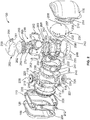
- FIG. 2 is an exploded view of the example apparatus 100 of FIG. 1 depicting the three separate pieces of the hermetic enclosure 102 (e.g., the covers 106 and 108 and the IMU mount 110).
- the fluid inlet port 126 is positioned on a top surface of the IMU mount 110 and the fluid output port 202 is positioned on the bottom surface of the IMU mount 110 opposite the fluid inlet port 126.
- the IMU mount 110 may also include an air inlet port 204 and a primary electrical connection 206 (e.g., a military standard electrical connection).
- the exploded view also depicts a first half 208 and a second half 210 of the isothermal dome 120 of FIG. 1 .
- the cooling tubes 124 are disposed on both the first and second halves 208 and 210 of the isothermal dome 120.
- the first and second halves 208 and 210 also include the first flange 212 and the second flange 214, respectively.
- the first and second flanges 212 and 214 are operative to couple to opposing surfaces of the gimbal mount 116.
- a remaining smooth, curved surface of each of the halves 208 and 210 fits within the gimbal mount 116.
- the first half 208 of the isothermal dome 120 includes an optical port 216.
- the optical port 216 may be operative during testing and/or calibration to enable a user to determine the position of a stable member 218 within the gimbal assembly 104. In some examples, the optical port 216 is excluded.
- the gimbal mount 116 includes a first aperture 219 and a second aperture 221 opposite the first aperture 219.
- the first aperture 219 may receive an outer gimbal motor 220 to control the position of the outer gimbal 222 based on feedback from one or more accelerometers or gyroscopes described in greater detail below.
- the second aperture 221 may receive an outer gimbal synchro 224 (e.g., an electrical resolver) to provide a signal representing an incremental, angular movement or position of the outer gimbal 222 relative to a zero point.
- Slip rings 226, 228 are disposed within the outer gimbal motor 220 and the outer gimbal synchro 224, respectively, to facilitate rotation of the outer gimbal 222 with electrical connection(s).
- the example outer gimbal motor 220 and outer gimbal synchro 224 include low friction bearings to facilitate rotation.
- the outer gimbal 222 is disposed within the gimbal mount 116 and coupled to the gimbal mount 116 via the outer gimbal motor 220, the outer gimbal synchro 224, and the slip rings 226 and 228.
- the outer gimbal 222 is substantially ring-shaped and two thermal shells 230 and 232 are coupled to either side of the outer gimbal 222 using fasteners disposed through holes 234 on the thermal shells 230 and 232.
- weights may be disposed in counter bores 236 of the isothermal shells 230 and 232. For example, weights may be added to one or more of the counter bores 236 to balance the isothermal shells 230 and/or 232.
- the outer gimbal 222 and the thermal shells 230 and 232 are machined as an assembly to achieve tight tolerances to provide the substantially small, uniform gaps (e.g., 0.0508 cm to 0.102 cm (0.020-0.040 inch)) between the layers (e.g., the outer gimbal 222 and isothermal dome 120) of the gimbal assembly 104.
- the outer gimbal 222 and the thermal shells 230 and 232 may be made of magnesium instead of aluminum or beryllium, which is typically used in gimbaled IMUs.
- the second thermal shell 232 includes an optical port 238 similar to the optical port 216 of the isothermal dome 120.
- the example outer gimbal 222 includes first and second apertures 239 and 241.
- the apertures 239 and 241 have a diameter larger than a width of the ring-shaped outer gimbal 222 and, thus, each of the thermal shells 230 and 232 includes curved indents (such as an indent 243) to accommodate for the apertures 239 and 241 in the outer gimbal 222.
- the first aperture 239 of the outer gimbal 222 includes a middle gimbal motor 240 to control a middle gimbal 242 based on feedback from one or more accelerometers and gyroscopes.
- the second aperture 241 of the outer gimbal 222 includes a middle gimbal synchro 244 to provide a signal representative of an incremental, angular movement or position of the middle gimbal 242 relative to a zero point.
- slip rings such as slip ring 246, are disposed within apertures of the middle gimbal motor 242 and/or the middle gimbal synchro 244 to facilitate rotation of the middle gimbal 242 with electrical connection(s).
- the example middle gimbal motor 240 and middle gimbal synchro 244 may include low friction bearings to facilitate rotation.
- the middle gimbal 242 is disposed within the outer gimbal 222 and coupled to the outer gimbal 222 via the middle gimbal motor 240, the middle gimbal synchro 244, and the slip rings 246.
- a slip ring 246 may be in connection with the middle gimbal synchro 244 and another such slip ring may be disposed in the middle gimbal motor 242.
- the middle gimbal 242 is substantially ring-shaped and two thermal shells 248 and 250 are coupled to respective opposing sides of the middle gimbal 242 using fasteners disposed through holes 252 passing through the thermal shells 248 and 250.
- the thermal shells 248 and 250 may include counter bores 254 in which weights may be disposed.
- Weights may be added to the counter bores 254 to balance the isothermal shells 248 and/or 250.
- the middle gimbal 242 and the thermal shells 248 and 250 are machined as an assembly to achieve tight tolerances to provide the substantially small gaps (e.g., 0.0508 cm to 0.102 cm (0.020-0.040 inch)) between the layers (e.g., the middle gimbal 242 and the outer gimbal 222) of the gimbal assembly 104.
- the middle gimbal 242 and the thermal shells 248 and 250 may also be made of magnesium.
- the middle gimbal 242 may include first and second opposing apertures 255 and 257.
- Each of the apertures 255 and 257 has a diameter greater than a width of the ring-shaped middle gimbal 242 and, thus, each of the thermal shells 248 and 250 includes curved indents, such as indent 251, to accommodate the apertures 255, 257 in the middle gimbal 242.
- the first aperture 255 of the middle gimbal 242 includes an inner gimbal motor 256 to control the stable member 218 (e.g., an inner gimbal) based on feedback from one or more accelerometers and gyroscopes.
- the second aperture 257 of the middle gimbal 242 includes an inner gimbal synchro 258 to provide a signal representative of an incremental, angular movement or position of the stable member 218 relative to a zero point.
- slip rings such as slip ring 260, are disposed within apertures of the inner gimbal motor 256 and/or the inner gimbal synchro 258 to facilitate rotation of the stable member 218 with electrical connection(s).
- the example inner gimbal motor 256 and middle gimbal synchro 258 may include low friction bearings to facilitate rotation.
- the stable member 218 is disposed within the middle gimbal 242 and coupled to the middle gimbal 242 via the inner gimbal motor 256, the inner gimbal synchro 258 and the slip rings 260.
- the stable member 218 includes one or more covers 262 to cover components of the IMU (e.g., electrical components, instruments, etc.).
- the covers 262 may be bolted onto the stable member 218 using holes disposed in the covers 262.
- the covers 262 are also shaped to maintain the overall spherical shape of the stable member 218 to maintain the gap between the stable member 218 and the middle gimbal 242 and thermal shells 248 and 250 substantially small (e.g., 0.0508 cm to 0.102 cm (0.020-0.040 inch)).
- the stable member 218 may be machined as an assembly to achieve tight tolerances to maintain the substantially small, uniform gap.
- the stable member 218 may be machined from a block of aluminum.
- the example stable member 218 includes a velocity sub system (VSS) 264 (e.g., an electronics assembly) that digitizes accelerometer instrument signals and may perform some or all data compensation algorithms.
- a rate subsystem (RSS) 266 is disposed in the stable member 218 opposite the VSS 264.
- the RSS 266 is an electronics assembly that digitizes gyroscope instrument signals and may perform some or all data compensation algorithms.
- One or more rings or shims 268 may be disposed adjacent each of the VSS 264 and the RSS 266 to separate the electronics assemblies from the other components and/or instruments (e.g., accelerometers, gyroscopes, etc.) disposed within the stable member 218.
- One or more of the rings 268 can include a heater or heating element 269 operative to maintain a constant temperature of the VSS 264 or RSS 266.
- the heater 269 may be operative when the VSS 264 or RSS 266 is not outputting a threshold amount of heat to account for a lower heat output from the VSS 264 or RSS 266 to the instruments within the stable member 218. Maintaining a constant temperature output of the VSS 264 and RSS 266 cavities of the stable member 218 and, more generally, the gimbal assembly 104 facilitates the temperature control of the gimbal assembly 104.
- the heat output by an electronics assembly can vary based on the current use of the electronics assembly (e.g., an electronics assembly not being used outputs less heat than an electronics assembly that is in use).
- the variation in the heat output by an electronics assembly can be difficult to predict and, thus, the temperature of the fluid in the cooling tubes 124 may not adequately account for the fluctuations in temperature from the VSS 264 and RSS 266 electronics assemblies because the temperature of the electronics assemblies may change more quickly than the temperature of the cooling fluid.
- Changing the temperature of a cooling fluid takes more time than turning on or off a heating element (e.g., a heater 269 disposed in the rings 268) disposed adjacent the electronics assemblies.
- the electronics assemblies 264 and 266 Due to the proximity of the electronics assemblies 264 and 266 to the instruments (e.g., the instruments used for navigation that must be kept at a constant temperature), a drop in temperature due to fluctuations in the heat output by the electronics assemblies could significantly affect the accuracy of the temperature-dependent instruments.
- the accuracy of these instruments is especially important because the IMU is an autonomous IMU not assisted by external instruments, such as a stellar star sensor, and continuous flight updates are not provided to an operator.
- the accuracy of the navigation of the vehicle in which the IMU is mounted may be critical (e.g., in the case where the vehicle is a missile) and may depend on maintaining the instruments at a stable temperature.
- one or more sensors may be included within the VSS 264, the RSS 266, and/or the cavities in which the electronics assemblies are disposed.
- An instrument cover (e.g., a plate) 270 is also disposed between each of the VSS 264 and the RSS 266 and the instruments within the stable member 218.
- the instrument cover 270 is operative to protect the instruments (e.g., the gyroscopes and accelerometers) from damage and may also provide an additional heat barrier between the electronics assemblies and the instruments.
- FIG. 3 is a cross-sectional view of the example apparatus 100 of FIG.1 .
- the stable member 218 includes instruments (e.g., gyroscopes, accelerometers) disposed within the stable member 218.
- instruments e.g., gyroscopes, accelerometers
- three gyroscopes are visible.
- the gyroscopes may include an x-direction gyroscope 302, a y-direction gyroscope 304, and a z-direction gyroscope 306.
- the illustrated example apparatus includes an x-direction accelerometer 308, a y-direction accelerometer 310, and a z-direction accelerometer, two of which are visible in the illustrated cross-section of FIG.
- the illustrated cross-section depicts an orthogonal (e.g., 90 degree) configuration of the accelerometers and the gyroscopes.
- the accelerometers and/or the gyroscopes may be configured differently.
- an alternate configuration may use two gyroscopes for flight information and one gyrocompass for location information.
- level detectors may be used to measure a local level of the apparatus.
- the apparatus may also include a mirror 312.
- the mirror 312 is operative to allow the operator to determine the position of the stable member 218 within the gimbal assembly 104.
- the mirror 312 may only used during testing and/or calibration.
- the apparatus 100 may not include a mirror 312.
- the mirror 312 is visible via the one or more optical ports 216 and 238 to enable alignment and/or calibration of the example apparatus 100 and/or gimbal assembly 104.
- FIG. 4 is a partial cross-sectional view of the example apparatus of FIG. 1 .
- the partial cross-section depicts the inter-gimbal gaps that are included in the gimbal assembly 104 to enable heat transfer via conduction.
- the inter-gimbal gaps include an outer gimbal gap 402, which is between the isothermal shell 120 and the outer gimbal 222 and/or the thermal shells 230, 232 coupled to the outer gimbal 222.
- a middle gimbal gap 404 is between the outer gimbal 222 and/or the thermal shells 230, 232 coupled to the outer gimbal 222 and the middle gimbal 242 and/or the thermal shells 248, 250 coupled to the middle gimbal 242.
- a stable member gap 406 is between the middle gimbal 242 and/or the thermal shells 248, 250 coupled to the middle gimbal 242 and the stable member 218.
- the example gaps 402, 404, and 406 have a width of 0.0508 cm to 0.102 cm (0.020 inch to 0.040 inch). Alternatively, the gaps may have a different width.
- the gaps 402, 404, and 406 are sized such that heat transfer due to convention is reduced (e.g., minimized, substantially reduced). Thus, heat transfer via conduction is facilitated by the substantially narrow gaps 402, 404, and 406.
- the gaps 402, 404, and 406 may have a nominal width of 0.0762 cm (0.030 inch).
- the example gaps 402, 404, and 406 are substantially uniform to enable accurate modeling of the heat transfer via conduction to maintain a temperature of the components within the stable member 218.
- a substantially uniform gap does not deviate from the nominal width of 0.0762 cm (0.030 inch) more than a designated tolerance (e.g., 0.0102 cm (0.004 inch) or 15%), which may be selected such that an actual heat transferred through the gap(s) does not differ from the modeled heat transfer an amount that prevents the temperature of the components from being properly maintained. Any variation in the width of the gaps may be due to machining tolerances associated with the gimbal components.
- the gaps 402, 404, and 406 may be filled by a gas composition or combination including nitrogen, helium, and/or neon gas.
- the combination is selected such that the gas promotes heat transfer via conduction but also remains stable (e.g., non-volatile).
- the position of each of the components e.g., gimbals, thermal shells, etc. is maintained to move no more than 0.0127cm (5 thousandths (0.005) of an inch)) from the initial position of the component.
- FIG. 5 is a block diagram of an inertial measurement unit 500.
- the example IMU 500 includes gyroscopes for each axis (e.g., the x-direction gyroscope 302, the y-direction gyroscope 304, and the z-direction gyroscope 306).
- the gyroscopes 302, 304, and 306 are operative to provide rotation information to the RSS electronics assembly 266 related to each axis.
- the RSS electronics assembly 266 processes the rotation information and provides feedback to the synchros (e.g., electrical resolvers) 224, 244, and 258 and/or motors 220, 240, and 256 so that the synchros 224, 244, and 258 and/or motors 220, 240, and 256 can adjust the position gimbals 218, 222, and 242 in the gimbal assembly 104.
- synchros e.g., electrical resolvers
- the IMU 500 also includes accelerometers for each axis (e.g., the x-direction accelerometer 308, the y-direction accelerometer 310, and a z-direction accelerometer 502).
- the accelerometers 308, 310, and 502 are operative to provide rotation information to the VSS electronics assembly 264 related to each axis.
- the VSS electronics assembly 264 processes the rotation information and provides feedback to the synchros (e.g., electrical resolvers) 224, 244, and 258 and/or motors 220, 240, and 256 so that the synchros 224, 244, and 258 and/or motors 220, 240, and 256 can adjust the position gimbals 218, 222, and 242 in the gimbal assembly 104.
- synchros e.g., electrical resolvers
- One or more multilayer thermal control elements 504 may be included in the example IMU 500.
- the multilayer thermal control elements 504 may be operative to perform active heat control for instruments as well as the stable member 218.
- the heaters 269 in the rings 268 within the stable member 218 may be controlled by and/or operatively coupled to the example multilayer thermal control elements 504.
- the chiller system may receive feedback from the multilayer thermal control elements 504 to control the temperature of the fluid flowing through the cooling tubes 124.
- the mechanical design of the example apparatus 100 also allows for passive heat control using liquid and gas conduction (e.g., via the cooling tubes 124 and/or the gas composition in the gaps (e.g., the gaps 402, 404, and 406 of FIG. 4 ).
- the example data packaging and communications system 506 may receive inputs from each of the RSS electronics assembly 266, the VSS electronics assembly 264, and the multilayer thermal control elements 504.
- the data packaging and communications system 506 communicates data between the RSS electronics assembly 266, the VSS electronics assembly 264, and/or the multilayer thermal control elements 504.
- the data packaging and communications system 506 performs control algorithms to control when the heaters 269 turn on and off and the temperature to which the heaters 269 may be set.
- the data packaging and communications system 506 also packages and communicates data with the gimbaled system (e.g., the motors, the synchros) and/or to a navigation system of the vehicle via the input/output for power and signals 508.
Landscapes
- Engineering & Computer Science (AREA)
- Physics & Mathematics (AREA)
- General Physics & Mathematics (AREA)
- Remote Sensing (AREA)
- Radar, Positioning & Navigation (AREA)
- Microelectronics & Electronic Packaging (AREA)
- Thermal Sciences (AREA)
- Aviation & Aerospace Engineering (AREA)
- Mechanical Engineering (AREA)
- General Engineering & Computer Science (AREA)
- Chemical & Material Sciences (AREA)
- Combustion & Propulsion (AREA)
- Gyroscopes (AREA)
- Measuring Volume Flow (AREA)
Abstract
Description
- This disclosure relates generally to gimbals and more, particularly, to conduction cooled gimbaled inertial measurement units.
- In some applications, inertial measurement units are used in navigation systems. The inertial measurement units are temperature sensitive and must be temperature controlled. Typically, inertial measurement units are cooled using an internal fan with flow diffusers. In some examples, internal bellyband cooling tubes may also be used to cool the inertial measurement unit.
- The invention relates to an apparatus which includes an inertial measurement unit, a gimbal assembly in which the inertial measurement unit is disposed, the gimbal assembly preferably having gaps between each gimbal of the gimbal assembly, the gaps preferably including a gas to conduct heat from the gimbal assembly, and an isothermal dome at least partially surrounding the gimbal assembly, the isothermal dome having a cooling tube disposed on an external surface of the isothermal dome to transfer heat from the gimbal assembly via conduction.
- The gimbal assembly can include a stable member, which stable member can include an electronics assembly disposed within a cavity of the stable member, an inertial measurement unit of a navigation system including a gyroscope and an accelerometer, the gyroscope and accelerometer disposed within the stable member, one or more gimbals operatively coupled to the stable member, each of the one or more gimbals including a thermal shell attached to a central portion of the gimbal to facilitate conductive heat transfer, and an isothermal dome at least partially surrounding the one or more gimbals, the isothermal dome including one or more cooling tubes to enable cooling of the inertial measurement unit via conductive heat transfer.
- To enhance performance under certain conditions, the gimbal assembly may include an outer gimbal, a middle gimbal, and stable member, each of the gimbals having a respective thermal shell to conduct heat to the isothermal dome.
- The isothermal dome may be cooled by a fluid flowing through the cooling tube, the fluid having a controlled temperature to maintain a substantially constant temperature of the inertial measurement unit via the conductive heat transfer. The inertial measurement unit may include an electronics assembly, gyroscopes, and accelerometers, wherein the electronics assembly is positioned within a cavity adjacent to the gyroscopes and accelerometers and separated from the gyroscopes and accelerometers by a plate. The apparatus may also include heaters disposed within the cavity, the heaters operative when an amount of heat output by the electronics assembly is below a threshold, the heaters to maintain a substantially constant temperature of the gimbal assembly. The gaps in the gimbal assembly may be sized to reduce convection flow within the gaps. The will improve efficiency. The gas is preferably thermally conductive and may include nitrogen, helium, or neon gas. The apparatus may also include a hermetic enclosure surrounding the isothermal dome. The gimbal assembly may be mounted to the hermetic enclosure using isolators disposed between the hermetic enclosure and the gimbal assembly, the isolators to reduce an interference to the inertial measurement unit from motion.
- The thermal shell may include two portions, the portions coupled to opposite sides of the central portion of each gimbal. The apparatus may also include heaters disposed within the stable member to maintain the stable member at a substantially constant temperature. The one or more cooling tubes may be used to convey a controlled temperature fluid to maintain a substantially constant temperature of the inertial measurement unit.
- The invention also relates to an apparatus that may include means for enclosing a gimbal assembly and means for providing a cooling fluid operatively coupled to the enclosing means, the cooling fluid to control a temperature of the gimbal assembly using conduction. The means for providing a cooling fluid may be disposed on an external surface of the enclosing means. The apparatus may also include means for conduction disposed within the gimbal assembly, the means for conduction to transfer heat from the gimbal assembly to the means for providing the cooling fluid.
-
-
FIG. 1 represents an example apparatus described herein. -
FIG. 2 is an exploded view of the example apparatus ofFIG. 1 . -
FIG. 3 is a cross-sectional view of the example apparatus ofFIG. 1 . -
FIG. 4 is a partial cross-sectional view of the example apparatus ofFIG. 1 . -
FIG. 5 is a block diagram of an example inertial measurement unit. - The figures are not to scale. Wherever possible, the same reference numbers will be used throughout the drawing(s) and accompanying written description to refer to the same or like parts.
- The apparatus disclosed herein is related to conduction cooled gimbaled inertial measurement units (IMUs). More specifically, the apparatus described herein is operative to maintain a gimbaled IMU at a substantially constant temperature using conduction heat transfer to cool the components of the IMU. Conduction heat transfer is implemented to cool the IMU due to the reliability (e.g., predictability, accuracy of a heat transfer model) of heat transfer via conduction versus, for example, heat transfer via convection.
- An example IMU of the example apparatus disclosed herein is an automatic IMU and does not require additional instruments (e.g., a stellar star sensor) to navigate or determine the positon of a vehicle in which the IMU is installed. The IMU may be disposed within a gimbal assembly including three gimbals having axes of rotation offset by 90 degrees. Thermal shells are operatively coupled to one or more of the gimbals to facilitate conductive heat transfer through the gimbal assembly. The gimbal assembly includes gaps sized (e.g., 0.0508 cm to 0.102 cm (0.020 inch to 0.040 inch)) to reduce (e.g., substantially prevent) convection flow and/or heat transfer due to the convection flow within the gaps. The gaps are uniform (e.g., the gaps are substantially the same width (varying between 0.0508 cm to 0.102 cm (0.020 inch to 0.040 inch)) from any portion of one gimbal or thermal shell to any portion of a second gimbal or second thermal shell) to facilitate conductive heat transfer. A gas disposed in the gaps and the gimbal assembly aids the conductive heat transfer and may be a composition including a combination of nitrogen, helium, and/or neon gas.
- The gimbal assembly may be disposed in an isothermal dome that at least partially surrounds the gimbal assembly. The isothermal dome is shaped and sized to maintain a substantially small gap between the outer gimbal and the dome to facilitate conductive heat transfer between the gimbal assembly and the isothermal dome. The isothermal dome includes cooling tubes operatively coupled to the surface of the dome, which aid conductive heat transfer and enable maintenance of a substantially constant temperature of the IMU. A fluid flowing through the cooling tubes may be temperature controlled using a chiller system that is external to the apparatus but within the vehicle in which the gimbal assembly is mounted to maintain the substantially constant temperature of the IMU. A hermetic enclosure surrounds the isothermal dome to provide an airtight seal around the apparatus to maintain the composition of the gas (e.g., a thermally conductive gas) disposed within the hermetic enclosure and/or the gaps of the gimbal assembly.
-
FIG. 1 represents anapparatus 100 that may be implemented to conductively cool a gimbaled IMU, such as, for example, an example IMU 500 depicted inFIG. 5 . Theexample apparatus 100 has a height of 38.862 cm (15.3 inches), a width of 41.91 cm (16.5 inches) and a depth of 33.02 cm (13.0 inches). However, the dimensions described herein are not limiting and in other examples theapparatus 100 may have different dimensions to accommodate a particular application. Additionally, theexample apparatus 100 may have a total weight of about 36.287 kg (80 pounds), where 29.937 kg (66 pounds) of that total weight is supported by isolators (e.g.,isolators 118 discussed in more detail below), and 21.772 kg (48 pounds) of the total weight is rotating as part of a gimbal assembly (e.g., agimbal assembly 104 discussed in more detail below). - The
example apparatus 100 includes ahermetic enclosure 102 completely surrounding thegimbal assembly 104 to maintain a gas composition or mixture (e.g., a gas composition including helium, nitrogen, and/or neon) within thehermetic enclosure 102. Alternatively, a liquid or liquid mixture may be disposed within thehermetic enclosure 102. In some examples, thehermetic enclosure 102 may be made out of a metal, such as aluminum or steel (e.g., stainless steel). Thehermetic enclosure 102 may include one or more seals disposedadjacent interfaces hermetic enclosure 102. For example, thehermetic enclosure 102 includes afront cover 106, aback cover 108, and anIMU mount 110, and seals may be disposed at theinterface 103 between thefront cover 106 and theIMU mount 110 and theinterface 105 between theback cover 106 and theIMU mount 110. - The IMU
mount 110 includes tabs ormounting brackets 112 to mount the apparatus in a vehicle (e.g., a spacecraft, an aircraft, a missile, etc.). Theexample tabs 112 includeholes 114 to receive respective fasteners (e.g., bolts). Thetabs 112 enable theapparatus 100 to be mounted in a vehicle such that theapparatus 100 can be serviced or maintained by removing a panel or opening a door on a side of the vehicle and, thus, does not require the vehicle to be dismantled to perform maintenance on theapparatus 100. In theexample apparatus 100, thetabs 112 are positioned at the corners of the IMUmount 110. Alternatively, thetabs 112 may be positioned on the sides of theIMU mount 110. Positioning thetabs 112 on theIMU mount 110 allows theexample apparatus 100 to be installed and/or removed as a whole by removing fasteners from thetabs 112, to facilitate installation and removal. - The
example gimbal assembly 104 is disposed within thehermetic enclosure 102. Thegimbal assembly 104 is coupled to theIMU mount 110 of thehermetic enclosure 102 via agimbal mount 116. Thegimbal mount 116 may be attached to theIMU mount 110 of thehermetic enclosure 102 using one or more isolators and/or shock absorbers 118 (e.g., elastomeric isolators). Theisolators 118 can reduce the vibration and/or interference experienced by thegimbal assembly 104 that may occur when the vehicle in which theapparatus 100 is positioned is in motion. Theisolators 118 are positioned within thehermetic enclosure 102 to facilitate maintenance of theapparatus 100 and/or eliminate the need for theapparatus 100 to include a flexible mounting structure to keep the IMU isolated from movement or interference in the environment (e.g., movement of the vehicle). Mounting thegimbal assembly 104 to theIMU mount 110 simplifies assembly of theapparatus 100 and does not require thecovers example apparatus 100 can be maintained or serviced without removing theapparatus 100 from the vehicle in which theapparatus 100 is installed because thecovers IMU mount 110 or any of thegimbal assembly 104 components. Thecovers gimbal assembly 104 from the external environment. - The
apparatus 100 also includes an exampleisothermal dome 120 to at least partially surround theexample gimbal assembly 104. The exampleisothermal dome 120 is coupled to a surface of thegimbal mount 116 via a flange (e.g., aflange FIG. 2 ) of theisothermal dome 120 and one or more fasteners (e.g., bolts) 122. A central portion of theisothermal dome 120 fits within theexample gimbal mount 116. As show in the exploded view ofFIG. 2 , theisothermal dome 120 includes two substantially similar halves coupled to thegimbal mount 116. Theisothermal dome 120 is sized to include a gap between an outer gimbal (e.g., anouter gimbal 222 ofFIG. 2 ) of thegimbal assembly 104 and the interior of theisothermal dome 120 that is substantially small (e.g., a gap that is approximately 0.0508 cm to 0.102 cm (0.020-0.040 inch)) such that the gap facilitates heat transfer via conduction and reduces (e.g., limits, substantially eliminates) heat transfer via convection. The reduction or elimination of heat transfer via convection allows for more predictable heat transfer and, thus, more accurate temperature control of thegimbal assembly 104. - A cooling coil or
tube 124 is disposed on an external (e.g., outer) surface of each half of theisothermal dome 120. The coolingtubes 124 are operative to control a temperature of an IMU disposed within thegimbal assembly 104 and/or maintain the temperature of theisothermal dome 120 substantially constant. In the illustrated example, the coolingtubes 124 are arranged in a spiral-like pattern. Alternatively, the coolingtubes 124 may be arranged in any other suitable pattern. Theexample cooling tubes 124 may be disposed within grooves on the surface of theisothermal dome 120 and/or fixed via brazing to the surface of theisothermal dome 120. Alternatively, the coolingtubes 124 may be attached to theisothermal dome 120 using any other suitable method including but not limited to welding, gluing, casting, etc. The coolingtubes 124 may be made of a metal such as, for example, aluminum or stainless steel. The coolingtubes 124 are operatively coupled to a chiller system external to theapparatus 100 via afluid inlet port 126 and a fluid outlet port (e.g.,fluid outlet port 202 ofFIG. 2 ). Alternatively or additionally, external thermoelectric coolers (e.g., TECs) are used to replace and/or supplement a chiller and/or cooling lines. In-flight cooling may, in some applications, use a bottle feed of compressed gas for cooling theisothermal dome 120. Aninlet tube 128 may be connected to thefluid inlet port 126 at the top (in the orientation shown inFIG. 1 ) of theIMU mount 110. Theinlet tube 128 may curve around the inside of thehermetic enclosure 102 and operatively couple to afirst end 130 of thecooling tube 124. Asecond end 132 of thecooling tube 124 is operatively coupled to anoutlet tube 134 disposed within thehermetic enclosure 102 and coupled to an outlet port positioned on a side of theIMU mount 110 opposite theinlet port 126. The inlet andoutlet tubes inlet port 126 is also coupled to an inlet tube and cooling tube on the other half of theisothermal dome 120. Similarly, a cooling tube on the other half of theisothermal dome 120 is coupled to an outlet tube and the outlet port. Thus, the fluid at theinlet port 126 splits into two portions or flow passages, each portion flowing through cooling tubes on respective halves of theisothermal dome 120, and both portions to recombine at the outlet port. Alternatively, the flow of the fluid may be reversed, thus making theinlet 126 the fluid outlet and theoutlet 134 the fluid inlet. - The cooling
tubes 124 contain a controlled temperature fluid (e.g., a cooling fluid) to maintain theisothermal dome 120 at a substantially constant temperature. The controlled temperature fluid may include sodium chromate, distilled water, glycol, etc. The temperature of the fluid is maintained at a specified fluid temperature using the chiller system external to theapparatus 100. The chiller system may include a controller to control the chiller system and maintain the fluid in thecooling tubes 124 at the specified fluid temperature. In some examples, the specified fluid temperature is selected based on a thermal model of conductive heat transfer through thegimbal assembly 104. Additionally or alternatively, the specified fluid temperature is adjusted based on sensors in thegimbal assembly 104. -
FIG. 2 is an exploded view of theexample apparatus 100 ofFIG. 1 depicting the three separate pieces of the hermetic enclosure 102 (e.g., thecovers fluid inlet port 126 is positioned on a top surface of theIMU mount 110 and thefluid output port 202 is positioned on the bottom surface of theIMU mount 110 opposite thefluid inlet port 126. TheIMU mount 110 may also include anair inlet port 204 and a primary electrical connection 206 (e.g., a military standard electrical connection). - The exploded view also depicts a
first half 208 and asecond half 210 of theisothermal dome 120 ofFIG. 1 . As discussed above, the coolingtubes 124 are disposed on both the first andsecond halves isothermal dome 120. The first andsecond halves first flange 212 and thesecond flange 214, respectively. The first andsecond flanges gimbal mount 116. A remaining smooth, curved surface of each of thehalves gimbal mount 116. In the illustrated example, thefirst half 208 of theisothermal dome 120 includes anoptical port 216. Theoptical port 216 may be operative during testing and/or calibration to enable a user to determine the position of astable member 218 within thegimbal assembly 104. In some examples, theoptical port 216 is excluded. - The
gimbal mount 116 includes afirst aperture 219 and asecond aperture 221 opposite thefirst aperture 219. Thefirst aperture 219 may receive anouter gimbal motor 220 to control the position of theouter gimbal 222 based on feedback from one or more accelerometers or gyroscopes described in greater detail below. Thesecond aperture 221 may receive an outer gimbal synchro 224 (e.g., an electrical resolver) to provide a signal representing an incremental, angular movement or position of theouter gimbal 222 relative to a zero point. Slip rings 226, 228 are disposed within theouter gimbal motor 220 and theouter gimbal synchro 224, respectively, to facilitate rotation of theouter gimbal 222 with electrical connection(s). The exampleouter gimbal motor 220 andouter gimbal synchro 224 include low friction bearings to facilitate rotation. - The
outer gimbal 222 is disposed within thegimbal mount 116 and coupled to thegimbal mount 116 via theouter gimbal motor 220, theouter gimbal synchro 224, and the slip rings 226 and 228. Theouter gimbal 222 is substantially ring-shaped and twothermal shells outer gimbal 222 using fasteners disposed throughholes 234 on thethermal shells isothermal shells isothermal shells 230 and/or 232. Theouter gimbal 222 and thethermal shells outer gimbal 222 and isothermal dome 120) of thegimbal assembly 104. Theouter gimbal 222 and thethermal shells thermal shell 232 includes anoptical port 238 similar to theoptical port 216 of theisothermal dome 120. - The example
outer gimbal 222 includes first andsecond apertures apertures outer gimbal 222 and, thus, each of thethermal shells apertures outer gimbal 222. Thefirst aperture 239 of theouter gimbal 222 includes amiddle gimbal motor 240 to control amiddle gimbal 242 based on feedback from one or more accelerometers and gyroscopes. Thesecond aperture 241 of theouter gimbal 222 includes a middle gimbal synchro 244 to provide a signal representative of an incremental, angular movement or position of themiddle gimbal 242 relative to a zero point. In some examples, slip rings, such asslip ring 246, are disposed within apertures of themiddle gimbal motor 242 and/or the middle gimbal synchro 244 to facilitate rotation of themiddle gimbal 242 with electrical connection(s). The examplemiddle gimbal motor 240 andmiddle gimbal synchro 244 may include low friction bearings to facilitate rotation. - The
middle gimbal 242 is disposed within theouter gimbal 222 and coupled to theouter gimbal 222 via themiddle gimbal motor 240, themiddle gimbal synchro 244, and the slip rings 246. Aslip ring 246 may be in connection with themiddle gimbal synchro 244 and another such slip ring may be disposed in themiddle gimbal motor 242. Themiddle gimbal 242 is substantially ring-shaped and twothermal shells middle gimbal 242 using fasteners disposed throughholes 252 passing through thethermal shells thermal shells isothermal shells 248 and/or 250. Themiddle gimbal 242 and thethermal shells middle gimbal 242 and the outer gimbal 222) of thegimbal assembly 104. Themiddle gimbal 242 and thethermal shells - The
middle gimbal 242 may include first and second opposingapertures apertures middle gimbal 242 and, thus, each of thethermal shells indent 251, to accommodate theapertures middle gimbal 242. Thefirst aperture 255 of themiddle gimbal 242 includes aninner gimbal motor 256 to control the stable member 218 (e.g., an inner gimbal) based on feedback from one or more accelerometers and gyroscopes. Thesecond aperture 257 of themiddle gimbal 242 includes aninner gimbal synchro 258 to provide a signal representative of an incremental, angular movement or position of thestable member 218 relative to a zero point. In some examples, slip rings, such asslip ring 260, are disposed within apertures of theinner gimbal motor 256 and/or theinner gimbal synchro 258 to facilitate rotation of thestable member 218 with electrical connection(s). The exampleinner gimbal motor 256 andmiddle gimbal synchro 258 may include low friction bearings to facilitate rotation. - The
stable member 218 is disposed within themiddle gimbal 242 and coupled to themiddle gimbal 242 via theinner gimbal motor 256, theinner gimbal synchro 258 and the slip rings 260. Thestable member 218 includes one ormore covers 262 to cover components of the IMU (e.g., electrical components, instruments, etc.). Thecovers 262 may be bolted onto thestable member 218 using holes disposed in thecovers 262. Thecovers 262 are also shaped to maintain the overall spherical shape of thestable member 218 to maintain the gap between thestable member 218 and themiddle gimbal 242 andthermal shells stable member 218 may be machined as an assembly to achieve tight tolerances to maintain the substantially small, uniform gap. For example, thestable member 218 may be machined from a block of aluminum. - The example
stable member 218 includes a velocity sub system (VSS) 264 (e.g., an electronics assembly) that digitizes accelerometer instrument signals and may perform some or all data compensation algorithms. A rate subsystem (RSS) 266 is disposed in thestable member 218 opposite theVSS 264. TheRSS 266 is an electronics assembly that digitizes gyroscope instrument signals and may perform some or all data compensation algorithms. One or more rings orshims 268 may be disposed adjacent each of theVSS 264 and theRSS 266 to separate the electronics assemblies from the other components and/or instruments (e.g., accelerometers, gyroscopes, etc.) disposed within thestable member 218. - One or more of the
rings 268 can include a heater orheating element 269 operative to maintain a constant temperature of theVSS 264 orRSS 266. For example, theheater 269 may be operative when theVSS 264 orRSS 266 is not outputting a threshold amount of heat to account for a lower heat output from theVSS 264 orRSS 266 to the instruments within thestable member 218. Maintaining a constant temperature output of theVSS 264 andRSS 266 cavities of thestable member 218 and, more generally, thegimbal assembly 104 facilitates the temperature control of thegimbal assembly 104. For example, the heat output by an electronics assembly (e.g., theVSS 264 or the RSS 266) can vary based on the current use of the electronics assembly (e.g., an electronics assembly not being used outputs less heat than an electronics assembly that is in use). The variation in the heat output by an electronics assembly can be difficult to predict and, thus, the temperature of the fluid in thecooling tubes 124 may not adequately account for the fluctuations in temperature from theVSS 264 andRSS 266 electronics assemblies because the temperature of the electronics assemblies may change more quickly than the temperature of the cooling fluid. Changing the temperature of a cooling fluid takes more time than turning on or off a heating element (e.g., aheater 269 disposed in the rings 268) disposed adjacent the electronics assemblies. - Due to the proximity of the
electronics assemblies heaters 269 in therings 268, one or more sensors may be included within theVSS 264, theRSS 266, and/or the cavities in which the electronics assemblies are disposed. - An instrument cover (e.g., a plate) 270 is also disposed between each of the
VSS 264 and theRSS 266 and the instruments within thestable member 218. Theinstrument cover 270 is operative to protect the instruments (e.g., the gyroscopes and accelerometers) from damage and may also provide an additional heat barrier between the electronics assemblies and the instruments. -
FIG. 3 is a cross-sectional view of theexample apparatus 100 ofFIG.1 . As shown inFIG. 3 , thestable member 218 includes instruments (e.g., gyroscopes, accelerometers) disposed within thestable member 218. In the illustrated example, three gyroscopes are visible. The gyroscopes may include anx-direction gyroscope 302, a y-direction gyroscope 304, and a z-direction gyroscope 306. Additionally, the illustrated example apparatus includes anx-direction accelerometer 308, a y-direction accelerometer 310, and a z-direction accelerometer, two of which are visible in the illustrated cross-section ofFIG. 3 . The illustrated cross-section depicts an orthogonal (e.g., 90 degree) configuration of the accelerometers and the gyroscopes. Alternatively, the accelerometers and/or the gyroscopes may be configured differently. For example, an alternate configuration may use two gyroscopes for flight information and one gyrocompass for location information. In some applications, level detectors may be used to measure a local level of the apparatus. - The apparatus may also include a
mirror 312. Themirror 312 is operative to allow the operator to determine the position of thestable member 218 within thegimbal assembly 104. Themirror 312 may only used during testing and/or calibration. Thus, theapparatus 100 may not include amirror 312. Themirror 312 is visible via the one or moreoptical ports example apparatus 100 and/orgimbal assembly 104. -
FIG. 4 is a partial cross-sectional view of the example apparatus ofFIG. 1 . The partial cross-section depicts the inter-gimbal gaps that are included in thegimbal assembly 104 to enable heat transfer via conduction. The inter-gimbal gaps include anouter gimbal gap 402, which is between theisothermal shell 120 and theouter gimbal 222 and/or thethermal shells outer gimbal 222. Amiddle gimbal gap 404 is between theouter gimbal 222 and/or thethermal shells outer gimbal 222 and themiddle gimbal 242 and/or thethermal shells middle gimbal 242. Astable member gap 406 is between themiddle gimbal 242 and/or thethermal shells middle gimbal 242 and thestable member 218. Theexample gaps gaps narrow gaps - The
gaps example gaps stable member 218. As used herein, a substantially uniform gap does not deviate from the nominal width of 0.0762 cm (0.030 inch) more than a designated tolerance (e.g., 0.0102 cm (0.004 inch) or 15%), which may be selected such that an actual heat transferred through the gap(s) does not differ from the modeled heat transfer an amount that prevents the temperature of the components from being properly maintained. Any variation in the width of the gaps may be due to machining tolerances associated with the gimbal components. - The
gaps -
FIG. 5 is a block diagram of aninertial measurement unit 500. Theexample IMU 500 includes gyroscopes for each axis (e.g., thex-direction gyroscope 302, the y-direction gyroscope 304, and the z-direction gyroscope 306). Thegyroscopes RSS electronics assembly 266 related to each axis. TheRSS electronics assembly 266 processes the rotation information and provides feedback to the synchros (e.g., electrical resolvers) 224, 244, and 258 and/ormotors synchros motors gimbal assembly 104. - The
IMU 500 also includes accelerometers for each axis (e.g., thex-direction accelerometer 308, the y-direction accelerometer 310, and a z-direction accelerometer 502). Theaccelerometers VSS electronics assembly 264 related to each axis. In some examples, theVSS electronics assembly 264 processes the rotation information and provides feedback to the synchros (e.g., electrical resolvers) 224, 244, and 258 and/ormotors synchros motors gimbal assembly 104. - One or more multilayer
thermal control elements 504 may be included in theexample IMU 500. The multilayerthermal control elements 504 may be operative to perform active heat control for instruments as well as thestable member 218. For example, theheaters 269 in therings 268 within thestable member 218 may be controlled by and/or operatively coupled to the example multilayerthermal control elements 504. In some examples, the chiller system may receive feedback from the multilayerthermal control elements 504 to control the temperature of the fluid flowing through the coolingtubes 124. The mechanical design of theexample apparatus 100 also allows for passive heat control using liquid and gas conduction (e.g., via thecooling tubes 124 and/or the gas composition in the gaps (e.g., thegaps FIG. 4 ). - The example data packaging and
communications system 506 may receive inputs from each of theRSS electronics assembly 266, theVSS electronics assembly 264, and the multilayerthermal control elements 504. The data packaging andcommunications system 506 communicates data between theRSS electronics assembly 266, theVSS electronics assembly 264, and/or the multilayerthermal control elements 504. In some examples, the data packaging andcommunications system 506 performs control algorithms to control when theheaters 269 turn on and off and the temperature to which theheaters 269 may be set. The data packaging andcommunications system 506 also packages and communicates data with the gimbaled system (e.g., the motors, the synchros) and/or to a navigation system of the vehicle via the input/output for power and signals 508. - From the foregoing, it will be appreciated that the above disclosed apparatus and articles of manufacture are operative to maintain a substantially constant temperature of a gimbal assembly and an automatic IMU using conduction cooling.
- Although certain example methods, apparatus and articles of manufacture have been disclosed herein, the scope of coverage of this patent is not limited thereto. On the contrary, this patent covers all methods, apparatus and articles of manufacture fairly falling within the scope of the claims of this patent.
Claims (15)
- An apparatus comprising:an inertial measurement unit, for example an inertial measurement unit of a navigation system,one or more gimbals associated with the inertial measurement unit, the gimbal configured to conduct heat transfer, andan isothermal dome at least partially surrounding the gimbal, the isothermal dome having a cooling tube disposed on an external surface of the isothermal dome to transfer heat from the gimbal.
- The apparatus of claim 1, wherein the gimbal is part of a gimbal assembly which assembly preferably includes an outer gimbal, a middle gimbal, and stable member, each of the gimbals having a respective thermal shell to conduct heat to the isothermal dome.
- The apparatus of claim 1 or claim 2, wherein the isothermal dome is cooled by a fluid flowing through the cooling tube, the fluid having a controlled temperature to maintain a substantially constant temperature of the inertial measurement unit.
- The apparatus of any of the preceding claims further comprising at least one gyroscope and at least one accelerometer, preferably wherein the gyroscope and the accelerometer are disposed in the inertial measurement unit.
- The apparatus of claim 4, further comprising an electronics assembly.
- The apparatus according to claim 5, wherein the electronics assembly is positioned within a cavity adjacent to the gyroscope and accelerometer and separated from the gyroscope and accelerometer by a plate.
- The apparatus of claim 5, wherein the electronics assembly is disposed within a cavity of a stable member of the gimbal assembly.
- The apparatus of claim 7, wherein the one or more gimbals are operatively coupled to the stable member, wherein the thermal shell of each of the one or more gimbals is attached to a central portion of the gimbal.
- The apparatus of claim 8, wherein the thermal shell includes two portions, the portions coupled to opposite sides of the central portion of each gimbal.
- The apparatus of any of the preceding claims wherein gaps are arranged between each gimbal.
- The apparatus according to claim 1, wherein the gaps include a gas to conduct heat from the gimbal assembly, which gas preferably includes one or more of nitrogen, helium or neon, and/or wherein the gaps are sized to reduce convection flow within the gaps.
- The apparatus according to any of the preceding claims further including at least one heater, which heater is configured to maintain the stable member and/or the gimbal at a substantially constant temperature, which heater is preferably disposed in the stable member, or disposed within the cavity of claim 4.
- The apparatus of claim 12, wherein, when the heater is disposed in the cavity, the heater is operative when an amount heat output by the electronics assembly is below a threshold.
- The apparatus of any of the preceding claims wherein the inertial measurement unit is maintained at a substantially constant temperature via conductive heat transfer and/or wherein the apparatus further includes a hermetic enclosure surrounding the isothermal dome.
- A navigation system for an aircraft comprising an apparatus according to any of the preceding claims.
Applications Claiming Priority (1)
| Application Number | Priority Date | Filing Date | Title |
|---|---|---|---|
| US15/015,855 US9986660B2 (en) | 2016-02-04 | 2016-02-04 | Conduction cooled autonomous gimbaled inertial measurement unit |
Publications (3)
| Publication Number | Publication Date |
|---|---|
| EP3203183A2 true EP3203183A2 (en) | 2017-08-09 |
| EP3203183A3 EP3203183A3 (en) | 2017-11-15 |
| EP3203183B1 EP3203183B1 (en) | 2019-11-06 |
Family
ID=57821838
Family Applications (1)
| Application Number | Title | Priority Date | Filing Date |
|---|---|---|---|
| EP17151552.1A Active EP3203183B1 (en) | 2016-02-04 | 2017-01-16 | Conduction cooled autonomous gimbaled inertial measurement unit |
Country Status (3)
| Country | Link |
|---|---|
| US (1) | US9986660B2 (en) |
| EP (1) | EP3203183B1 (en) |
| RU (1) | RU2736895C2 (en) |
Cited By (1)
| Publication number | Priority date | Publication date | Assignee | Title |
|---|---|---|---|---|
| WO2020114525A1 (en) * | 2018-12-05 | 2020-06-11 | 顺丰科技有限公司 | Avionic structure of unmanned aerial vehicle and unmanned aerial vehicle |
Families Citing this family (8)
| Publication number | Priority date | Publication date | Assignee | Title |
|---|---|---|---|---|
| US9673635B2 (en) * | 2014-12-15 | 2017-06-06 | Tyco Fire & Security Gmbh | Self sustaining energy harvesting system |
| US11085793B2 (en) | 2016-10-03 | 2021-08-10 | Government Of The United States Of America, As Represented By The Secretary Of Commerce | Inertial measurement unit and diagnostic system |
| US10732586B2 (en) * | 2017-07-12 | 2020-08-04 | X Development Llc | Active disturbance compensation for physically changing systems |
| US10732193B2 (en) * | 2018-02-19 | 2020-08-04 | The Boeing Company | Open architecture gimbaled navigation system using lattice shells |
| TWI750717B (en) * | 2020-06-30 | 2021-12-21 | 崇濬科技股份有限公司 | Heat insulation member and heating assembly |
| US12326350B2 (en) | 2021-03-16 | 2025-06-10 | The Boeing Company | Real-time onboard standalone sensor thermal compensation (RToB SSTC) techniques and tools for induced error reduction |
| DE102021109748A1 (en) * | 2021-04-19 | 2022-10-20 | Isud Solutions Gmbh | Optical analysis device for determining a parameter of a medium, housing and overall system |
| CN119223261B (en) * | 2024-12-03 | 2025-02-25 | 四川图林科技有限责任公司 | System and method for suppressing temperature fluctuation error based on gyroscope |
Family Cites Families (5)
| Publication number | Priority date | Publication date | Assignee | Title |
|---|---|---|---|---|
| US3216263A (en) * | 1959-09-29 | 1965-11-09 | Rand Corp | Superconducting gyroscopic apparatus |
| US3812727A (en) * | 1970-11-24 | 1974-05-28 | Edcliff Instr | Accelerometer |
| US5097899A (en) * | 1989-05-30 | 1992-03-24 | The Charles Stark Draper Laboratories | Shell with integral internal passage and method of making same |
| WO2007020701A1 (en) * | 2005-08-18 | 2007-02-22 | C & N Inc | Acceleration sensor |
| RU2567094C1 (en) * | 2014-07-08 | 2015-10-27 | Открытое акционерное общество "Завод им. В.А. Дегтярева" | Inertial navigation system temperature stabiliser |
-
2016
- 2016-02-04 US US15/015,855 patent/US9986660B2/en active Active
-
2017
- 2017-01-16 EP EP17151552.1A patent/EP3203183B1/en active Active
- 2017-01-20 RU RU2017101875A patent/RU2736895C2/en active
Non-Patent Citations (1)
| Title |
|---|
| None |
Cited By (1)
| Publication number | Priority date | Publication date | Assignee | Title |
|---|---|---|---|---|
| WO2020114525A1 (en) * | 2018-12-05 | 2020-06-11 | 顺丰科技有限公司 | Avionic structure of unmanned aerial vehicle and unmanned aerial vehicle |
Also Published As
| Publication number | Publication date |
|---|---|
| US9986660B2 (en) | 2018-05-29 |
| RU2017101875A3 (en) | 2020-05-15 |
| EP3203183B1 (en) | 2019-11-06 |
| RU2017101875A (en) | 2018-07-20 |
| US20170231114A1 (en) | 2017-08-10 |
| RU2736895C2 (en) | 2020-11-23 |
| EP3203183A3 (en) | 2017-11-15 |
Similar Documents
| Publication | Publication Date | Title |
|---|---|---|
| EP3203183B1 (en) | Conduction cooled autonomous gimbaled inertial measurement unit | |
| EP3105492B1 (en) | Platform stabilization system | |
| EP1810502B1 (en) | System and method for stabilizing an image | |
| EP3093619B1 (en) | Multi-axis center of mass balancing system for an optical gimbal assembly guided by inertial measurement | |
| US20180135798A1 (en) | Gimbal Stabilization System and Method | |
| CN104777842B (en) | Satellite single-axis measurement and control integrated method based on magnetic suspension control sensitive gyroscope | |
| US20130129337A1 (en) | Separation of main and secondary inertial measurements for improved line of sight error of an imaging vehicle's isolated detector assembly | |
| Peck et al. | An airbearing-based testbed for momentum control systems and spacecraft line of sight | |
| US7762133B2 (en) | Inertial measurement unit with gas plenums | |
| Reinacher et al. | The SOFIA telescope in full operation | |
| US11879735B2 (en) | Gyroscope using torus shaped channels and image processing | |
| RU2423658C2 (en) | Method of controlling and stabilising mobile carrier, integrated system, device for turning antenna reflector in two mutually-perpendicular planes and device for actuating differential aerodynamic controllers for realising said method | |
| Tiliakos | MEMS for harsh environment sensors in aerospace applications: selected case studies | |
| Ivanov et al. | Laboratory facility for microsatellite mock-up motion simulation | |
| US20260126291A1 (en) | Spatial orientation indication device | |
| WO2024084452A1 (en) | Spatial orientation indication device | |
| Harp et al. | Developing a practical, high accuracy attitude determination system for CubeSats. | |
| Vredevoogd et al. | Development of a Gimbal Actuated Powered Descent Vehicle | |
| Fritz et al. | A miniaturized pointing mount for Spacelab missions | |
| MARIANI | Design and development of a small satellites three axis attitude simulation platform | |
| Peterson et al. | Six DOF high-frequency motion simulator phase II | |
| Joshi | Analysis of a magnetically suspended, high-performance instrument pointing system | |
| Liu et al. | Design of attitude and heading reference system based on MEMS sensor | |
| Angus et al. | The guidance system for Ariane | |
| Jaworski et al. | New Low-Cost Video Camera Pointing |
Legal Events
| Date | Code | Title | Description |
|---|---|---|---|
| PUAI | Public reference made under article 153(3) epc to a published international application that has entered the european phase |
Free format text: ORIGINAL CODE: 0009012 |
|
| STAA | Information on the status of an ep patent application or granted ep patent |
Free format text: STATUS: REQUEST FOR EXAMINATION WAS MADE |
|
| 17P | Request for examination filed |
Effective date: 20170116 |
|
| AK | Designated contracting states |
Kind code of ref document: A2 Designated state(s): AL AT BE BG CH CY CZ DE DK EE ES FI FR GB GR HR HU IE IS IT LI LT LU LV MC MK MT NL NO PL PT RO RS SE SI SK SM TR |
|
| AX | Request for extension of the european patent |
Extension state: BA ME |
|
| PUAL | Search report despatched |
Free format text: ORIGINAL CODE: 0009013 |
|
| AK | Designated contracting states |
Kind code of ref document: A3 Designated state(s): AL AT BE BG CH CY CZ DE DK EE ES FI FR GB GR HR HU IE IS IT LI LT LU LV MC MK MT NL NO PL PT RO RS SE SI SK SM TR |
|
| AX | Request for extension of the european patent |
Extension state: BA ME |
|
| RIC1 | Information provided on ipc code assigned before grant |
Ipc: B21D 53/04 20060101ALI20171009BHEP Ipc: F28F 3/12 20060101ALI20171009BHEP Ipc: G01C 19/04 20060101AFI20171009BHEP Ipc: G01C 19/20 20060101ALI20171009BHEP |
|
| RIC1 | Information provided on ipc code assigned before grant |
Ipc: G01C 19/04 20060101AFI20180905BHEP Ipc: G01C 19/20 20060101ALI20180905BHEP |
|
| GRAP | Despatch of communication of intention to grant a patent |
Free format text: ORIGINAL CODE: EPIDOSNIGR1 |
|
| STAA | Information on the status of an ep patent application or granted ep patent |
Free format text: STATUS: GRANT OF PATENT IS INTENDED |
|
| INTG | Intention to grant announced |
Effective date: 20181026 |
|
| RIN1 | Information on inventor provided before grant (corrected) |
Inventor name: TEMPLETON, JOSEPH Inventor name: MERNA, DWAYNE Inventor name: GINGRICH, JAMES K. Inventor name: JUSTIN, JOSEPH E. Inventor name: BUTSCHER, STEPHEN Inventor name: DETLOFF, SHAUN |
|
| GRAJ | Information related to disapproval of communication of intention to grant by the applicant or resumption of examination proceedings by the epo deleted |
Free format text: ORIGINAL CODE: EPIDOSDIGR1 |
|
| STAA | Information on the status of an ep patent application or granted ep patent |
Free format text: STATUS: REQUEST FOR EXAMINATION WAS MADE |
|
| INTC | Intention to grant announced (deleted) | ||
| GRAP | Despatch of communication of intention to grant a patent |
Free format text: ORIGINAL CODE: EPIDOSNIGR1 |
|
| STAA | Information on the status of an ep patent application or granted ep patent |
Free format text: STATUS: GRANT OF PATENT IS INTENDED |
|
| INTG | Intention to grant announced |
Effective date: 20190423 |
|
| GRAS | Grant fee paid |
Free format text: ORIGINAL CODE: EPIDOSNIGR3 |
|
| GRAJ | Information related to disapproval of communication of intention to grant by the applicant or resumption of examination proceedings by the epo deleted |
Free format text: ORIGINAL CODE: EPIDOSDIGR1 |
|
| GRAL | Information related to payment of fee for publishing/printing deleted |
Free format text: ORIGINAL CODE: EPIDOSDIGR3 |
|
| STAA | Information on the status of an ep patent application or granted ep patent |
Free format text: STATUS: REQUEST FOR EXAMINATION WAS MADE |
|
| GRAP | Despatch of communication of intention to grant a patent |
Free format text: ORIGINAL CODE: EPIDOSNIGR1 |
|
| STAA | Information on the status of an ep patent application or granted ep patent |
Free format text: STATUS: GRANT OF PATENT IS INTENDED |
|
| INTC | Intention to grant announced (deleted) | ||
| GRAA | (expected) grant |
Free format text: ORIGINAL CODE: 0009210 |
|
| STAA | Information on the status of an ep patent application or granted ep patent |
Free format text: STATUS: THE PATENT HAS BEEN GRANTED |
|
| INTG | Intention to grant announced |
Effective date: 20190927 |
|
| RIN1 | Information on inventor provided before grant (corrected) |
Inventor name: JUSTIN, JOSEPH E. Inventor name: TEMPLETON, JOSEPH Inventor name: MERNA, DWAYNE Inventor name: DETLOFF, SHAUN Inventor name: BUTSCHER, STEPHEN Inventor name: GINGRICH, JAMES K. |
|
| AK | Designated contracting states |
Kind code of ref document: B1 Designated state(s): AL AT BE BG CH CY CZ DE DK EE ES FI FR GB GR HR HU IE IS IT LI LT LU LV MC MK MT NL NO PL PT RO RS SE SI SK SM TR |
|
| REG | Reference to a national code |
Ref country code: GB Ref legal event code: FG4D |
|
| REG | Reference to a national code |
Ref country code: CH Ref legal event code: EP Ref country code: AT Ref legal event code: REF Ref document number: 1199349 Country of ref document: AT Kind code of ref document: T Effective date: 20191115 |
|
| REG | Reference to a national code |
Ref country code: IE Ref legal event code: FG4D |
|
| REG | Reference to a national code |
Ref country code: DE Ref legal event code: R096 Ref document number: 602017008300 Country of ref document: DE |
|
| REG | Reference to a national code |
Ref country code: NL Ref legal event code: MP Effective date: 20191106 |
|
| REG | Reference to a national code |
Ref country code: LT Ref legal event code: MG4D |
|
| PG25 | Lapsed in a contracting state [announced via postgrant information from national office to epo] |
Ref country code: SE Free format text: LAPSE BECAUSE OF FAILURE TO SUBMIT A TRANSLATION OF THE DESCRIPTION OR TO PAY THE FEE WITHIN THE PRESCRIBED TIME-LIMIT Effective date: 20191106 Ref country code: NL Free format text: LAPSE BECAUSE OF FAILURE TO SUBMIT A TRANSLATION OF THE DESCRIPTION OR TO PAY THE FEE WITHIN THE PRESCRIBED TIME-LIMIT Effective date: 20191106 Ref country code: LV Free format text: LAPSE BECAUSE OF FAILURE TO SUBMIT A TRANSLATION OF THE DESCRIPTION OR TO PAY THE FEE WITHIN THE PRESCRIBED TIME-LIMIT Effective date: 20191106 Ref country code: LT Free format text: LAPSE BECAUSE OF FAILURE TO SUBMIT A TRANSLATION OF THE DESCRIPTION OR TO PAY THE FEE WITHIN THE PRESCRIBED TIME-LIMIT Effective date: 20191106 Ref country code: GR Free format text: LAPSE BECAUSE OF FAILURE TO SUBMIT A TRANSLATION OF THE DESCRIPTION OR TO PAY THE FEE WITHIN THE PRESCRIBED TIME-LIMIT Effective date: 20200207 Ref country code: PT Free format text: LAPSE BECAUSE OF FAILURE TO SUBMIT A TRANSLATION OF THE DESCRIPTION OR TO PAY THE FEE WITHIN THE PRESCRIBED TIME-LIMIT Effective date: 20200306 Ref country code: PL Free format text: LAPSE BECAUSE OF FAILURE TO SUBMIT A TRANSLATION OF THE DESCRIPTION OR TO PAY THE FEE WITHIN THE PRESCRIBED TIME-LIMIT Effective date: 20191106 Ref country code: NO Free format text: LAPSE BECAUSE OF FAILURE TO SUBMIT A TRANSLATION OF THE DESCRIPTION OR TO PAY THE FEE WITHIN THE PRESCRIBED TIME-LIMIT Effective date: 20200206 Ref country code: FI Free format text: LAPSE BECAUSE OF FAILURE TO SUBMIT A TRANSLATION OF THE DESCRIPTION OR TO PAY THE FEE WITHIN THE PRESCRIBED TIME-LIMIT Effective date: 20191106 Ref country code: BG Free format text: LAPSE BECAUSE OF FAILURE TO SUBMIT A TRANSLATION OF THE DESCRIPTION OR TO PAY THE FEE WITHIN THE PRESCRIBED TIME-LIMIT Effective date: 20200206 |
|
| PG25 | Lapsed in a contracting state [announced via postgrant information from national office to epo] |
Ref country code: HR Free format text: LAPSE BECAUSE OF FAILURE TO SUBMIT A TRANSLATION OF THE DESCRIPTION OR TO PAY THE FEE WITHIN THE PRESCRIBED TIME-LIMIT Effective date: 20191106 Ref country code: RS Free format text: LAPSE BECAUSE OF FAILURE TO SUBMIT A TRANSLATION OF THE DESCRIPTION OR TO PAY THE FEE WITHIN THE PRESCRIBED TIME-LIMIT Effective date: 20191106 Ref country code: IS Free format text: LAPSE BECAUSE OF FAILURE TO SUBMIT A TRANSLATION OF THE DESCRIPTION OR TO PAY THE FEE WITHIN THE PRESCRIBED TIME-LIMIT Effective date: 20200306 |
|
| PG25 | Lapsed in a contracting state [announced via postgrant information from national office to epo] |
Ref country code: AL Free format text: LAPSE BECAUSE OF FAILURE TO SUBMIT A TRANSLATION OF THE DESCRIPTION OR TO PAY THE FEE WITHIN THE PRESCRIBED TIME-LIMIT Effective date: 20191106 |
|
| PG25 | Lapsed in a contracting state [announced via postgrant information from national office to epo] |
Ref country code: CZ Free format text: LAPSE BECAUSE OF FAILURE TO SUBMIT A TRANSLATION OF THE DESCRIPTION OR TO PAY THE FEE WITHIN THE PRESCRIBED TIME-LIMIT Effective date: 20191106 Ref country code: RO Free format text: LAPSE BECAUSE OF FAILURE TO SUBMIT A TRANSLATION OF THE DESCRIPTION OR TO PAY THE FEE WITHIN THE PRESCRIBED TIME-LIMIT Effective date: 20191106 Ref country code: EE Free format text: LAPSE BECAUSE OF FAILURE TO SUBMIT A TRANSLATION OF THE DESCRIPTION OR TO PAY THE FEE WITHIN THE PRESCRIBED TIME-LIMIT Effective date: 20191106 Ref country code: DK Free format text: LAPSE BECAUSE OF FAILURE TO SUBMIT A TRANSLATION OF THE DESCRIPTION OR TO PAY THE FEE WITHIN THE PRESCRIBED TIME-LIMIT Effective date: 20191106 Ref country code: ES Free format text: LAPSE BECAUSE OF FAILURE TO SUBMIT A TRANSLATION OF THE DESCRIPTION OR TO PAY THE FEE WITHIN THE PRESCRIBED TIME-LIMIT Effective date: 20191106 |
|
| REG | Reference to a national code |
Ref country code: DE Ref legal event code: R097 Ref document number: 602017008300 Country of ref document: DE |
|
| REG | Reference to a national code |
Ref country code: AT Ref legal event code: MK05 Ref document number: 1199349 Country of ref document: AT Kind code of ref document: T Effective date: 20191106 |
|
| PG25 | Lapsed in a contracting state [announced via postgrant information from national office to epo] |
Ref country code: SK Free format text: LAPSE BECAUSE OF FAILURE TO SUBMIT A TRANSLATION OF THE DESCRIPTION OR TO PAY THE FEE WITHIN THE PRESCRIBED TIME-LIMIT Effective date: 20191106 Ref country code: SM Free format text: LAPSE BECAUSE OF FAILURE TO SUBMIT A TRANSLATION OF THE DESCRIPTION OR TO PAY THE FEE WITHIN THE PRESCRIBED TIME-LIMIT Effective date: 20191106 Ref country code: MC Free format text: LAPSE BECAUSE OF FAILURE TO SUBMIT A TRANSLATION OF THE DESCRIPTION OR TO PAY THE FEE WITHIN THE PRESCRIBED TIME-LIMIT Effective date: 20191106 |
|
| REG | Reference to a national code |
Ref country code: CH Ref legal event code: PL |
|
| PLBE | No opposition filed within time limit |
Free format text: ORIGINAL CODE: 0009261 |
|
| STAA | Information on the status of an ep patent application or granted ep patent |
Free format text: STATUS: NO OPPOSITION FILED WITHIN TIME LIMIT |
|
| 26N | No opposition filed |
Effective date: 20200807 |
|
| REG | Reference to a national code |
Ref country code: BE Ref legal event code: MM Effective date: 20200131 |
|
| PG25 | Lapsed in a contracting state [announced via postgrant information from national office to epo] |
Ref country code: LU Free format text: LAPSE BECAUSE OF NON-PAYMENT OF DUE FEES Effective date: 20200116 |
|
| PG25 | Lapsed in a contracting state [announced via postgrant information from national office to epo] |
Ref country code: BE Free format text: LAPSE BECAUSE OF NON-PAYMENT OF DUE FEES Effective date: 20200131 Ref country code: AT Free format text: LAPSE BECAUSE OF FAILURE TO SUBMIT A TRANSLATION OF THE DESCRIPTION OR TO PAY THE FEE WITHIN THE PRESCRIBED TIME-LIMIT Effective date: 20191106 Ref country code: SI Free format text: LAPSE BECAUSE OF FAILURE TO SUBMIT A TRANSLATION OF THE DESCRIPTION OR TO PAY THE FEE WITHIN THE PRESCRIBED TIME-LIMIT Effective date: 20191106 Ref country code: LI Free format text: LAPSE BECAUSE OF NON-PAYMENT OF DUE FEES Effective date: 20200131 Ref country code: CH Free format text: LAPSE BECAUSE OF NON-PAYMENT OF DUE FEES Effective date: 20200131 |
|
| PG25 | Lapsed in a contracting state [announced via postgrant information from national office to epo] |
Ref country code: IT Free format text: LAPSE BECAUSE OF FAILURE TO SUBMIT A TRANSLATION OF THE DESCRIPTION OR TO PAY THE FEE WITHIN THE PRESCRIBED TIME-LIMIT Effective date: 20191106 Ref country code: IE Free format text: LAPSE BECAUSE OF NON-PAYMENT OF DUE FEES Effective date: 20200116 |
|
| PG25 | Lapsed in a contracting state [announced via postgrant information from national office to epo] |
Ref country code: TR Free format text: LAPSE BECAUSE OF FAILURE TO SUBMIT A TRANSLATION OF THE DESCRIPTION OR TO PAY THE FEE WITHIN THE PRESCRIBED TIME-LIMIT Effective date: 20191106 Ref country code: MT Free format text: LAPSE BECAUSE OF FAILURE TO SUBMIT A TRANSLATION OF THE DESCRIPTION OR TO PAY THE FEE WITHIN THE PRESCRIBED TIME-LIMIT Effective date: 20191106 Ref country code: CY Free format text: LAPSE BECAUSE OF FAILURE TO SUBMIT A TRANSLATION OF THE DESCRIPTION OR TO PAY THE FEE WITHIN THE PRESCRIBED TIME-LIMIT Effective date: 20191106 |
|
| PG25 | Lapsed in a contracting state [announced via postgrant information from national office to epo] |
Ref country code: MK Free format text: LAPSE BECAUSE OF FAILURE TO SUBMIT A TRANSLATION OF THE DESCRIPTION OR TO PAY THE FEE WITHIN THE PRESCRIBED TIME-LIMIT Effective date: 20191106 |
|
| P01 | Opt-out of the competence of the unified patent court (upc) registered |
Effective date: 20230516 |
|
| PGFP | Annual fee paid to national office [announced via postgrant information from national office to epo] |
Ref country code: DE Payment date: 20250129 Year of fee payment: 9 |
|
| PGFP | Annual fee paid to national office [announced via postgrant information from national office to epo] |
Ref country code: FR Payment date: 20250127 Year of fee payment: 9 |
|
| PGFP | Annual fee paid to national office [announced via postgrant information from national office to epo] |
Ref country code: GB Payment date: 20250127 Year of fee payment: 9 |