EP3203046A1 - Heat-insulated pipe arrangement - Google Patents
Heat-insulated pipe arrangement Download PDFInfo
- Publication number
- EP3203046A1 EP3203046A1 EP15847946.9A EP15847946A EP3203046A1 EP 3203046 A1 EP3203046 A1 EP 3203046A1 EP 15847946 A EP15847946 A EP 15847946A EP 3203046 A1 EP3203046 A1 EP 3203046A1
- Authority
- EP
- European Patent Office
- Prior art keywords
- heat
- pipe
- insulating member
- insulated
- heat insulating
- Prior art date
- Legal status (The legal status is an assumption and is not a legal conclusion. Google has not performed a legal analysis and makes no representation as to the accuracy of the status listed.)
- Withdrawn
Links
Images

Classifications
-
- F—MECHANICAL ENGINEERING; LIGHTING; HEATING; WEAPONS; BLASTING
- F16—ENGINEERING ELEMENTS AND UNITS; GENERAL MEASURES FOR PRODUCING AND MAINTAINING EFFECTIVE FUNCTIONING OF MACHINES OR INSTALLATIONS; THERMAL INSULATION IN GENERAL
- F16L—PIPES; JOINTS OR FITTINGS FOR PIPES; SUPPORTS FOR PIPES, CABLES OR PROTECTIVE TUBING; MEANS FOR THERMAL INSULATION IN GENERAL
- F16L59/00—Thermal insulation in general
- F16L59/02—Shape or form of insulating materials, with or without coverings integral with the insulating materials
- F16L59/021—Shape or form of insulating materials, with or without coverings integral with the insulating materials comprising a single piece or sleeve, e.g. split sleeve, two half sleeves
- F16L59/022—Shape or form of insulating materials, with or without coverings integral with the insulating materials comprising a single piece or sleeve, e.g. split sleeve, two half sleeves with a single slit
-
- F—MECHANICAL ENGINEERING; LIGHTING; HEATING; WEAPONS; BLASTING
- F01—MACHINES OR ENGINES IN GENERAL; ENGINE PLANTS IN GENERAL; STEAM ENGINES
- F01N—GAS-FLOW SILENCERS OR EXHAUST APPARATUS FOR MACHINES OR ENGINES IN GENERAL; GAS-FLOW SILENCERS OR EXHAUST APPARATUS FOR INTERNAL COMBUSTION ENGINES
- F01N13/00—Exhaust or silencing apparatus characterised by constructional features ; Exhaust or silencing apparatus, or parts thereof, having pertinent characteristics not provided for in, or of interest apart from, groups F01N1/00 - F01N5/00, F01N9/00, F01N11/00
- F01N13/14—Exhaust or silencing apparatus characterised by constructional features ; Exhaust or silencing apparatus, or parts thereof, having pertinent characteristics not provided for in, or of interest apart from, groups F01N1/00 - F01N5/00, F01N9/00, F01N11/00 having thermal insulation
-
- F—MECHANICAL ENGINEERING; LIGHTING; HEATING; WEAPONS; BLASTING
- F01—MACHINES OR ENGINES IN GENERAL; ENGINE PLANTS IN GENERAL; STEAM ENGINES
- F01N—GAS-FLOW SILENCERS OR EXHAUST APPARATUS FOR MACHINES OR ENGINES IN GENERAL; GAS-FLOW SILENCERS OR EXHAUST APPARATUS FOR INTERNAL COMBUSTION ENGINES
- F01N3/00—Exhaust or silencing apparatus having means for purifying, rendering innocuous, or otherwise treating exhaust
- F01N3/08—Exhaust or silencing apparatus having means for purifying, rendering innocuous, or otherwise treating exhaust for rendering innocuous
- F01N3/10—Exhaust or silencing apparatus having means for purifying, rendering innocuous, or otherwise treating exhaust for rendering innocuous by thermal or catalytic conversion of noxious components of exhaust
- F01N3/18—Exhaust or silencing apparatus having means for purifying, rendering innocuous, or otherwise treating exhaust for rendering innocuous by thermal or catalytic conversion of noxious components of exhaust characterised by methods of operation; Control
- F01N3/20—Exhaust or silencing apparatus having means for purifying, rendering innocuous, or otherwise treating exhaust for rendering innocuous by thermal or catalytic conversion of noxious components of exhaust characterised by methods of operation; Control specially adapted for catalytic conversion ; Methods of operation or control of catalytic converters
- F01N3/2066—Selective catalytic reduction [SCR]
-
- F—MECHANICAL ENGINEERING; LIGHTING; HEATING; WEAPONS; BLASTING
- F01—MACHINES OR ENGINES IN GENERAL; ENGINE PLANTS IN GENERAL; STEAM ENGINES
- F01N—GAS-FLOW SILENCERS OR EXHAUST APPARATUS FOR MACHINES OR ENGINES IN GENERAL; GAS-FLOW SILENCERS OR EXHAUST APPARATUS FOR INTERNAL COMBUSTION ENGINES
- F01N3/00—Exhaust or silencing apparatus having means for purifying, rendering innocuous, or otherwise treating exhaust
- F01N3/08—Exhaust or silencing apparatus having means for purifying, rendering innocuous, or otherwise treating exhaust for rendering innocuous
- F01N3/10—Exhaust or silencing apparatus having means for purifying, rendering innocuous, or otherwise treating exhaust for rendering innocuous by thermal or catalytic conversion of noxious components of exhaust
- F01N3/24—Exhaust or silencing apparatus having means for purifying, rendering innocuous, or otherwise treating exhaust for rendering innocuous by thermal or catalytic conversion of noxious components of exhaust characterised by constructional aspects of converting apparatus
- F01N3/26—Construction of thermal reactors
-
- F—MECHANICAL ENGINEERING; LIGHTING; HEATING; WEAPONS; BLASTING
- F16—ENGINEERING ELEMENTS AND UNITS; GENERAL MEASURES FOR PRODUCING AND MAINTAINING EFFECTIVE FUNCTIONING OF MACHINES OR INSTALLATIONS; THERMAL INSULATION IN GENERAL
- F16L—PIPES; JOINTS OR FITTINGS FOR PIPES; SUPPORTS FOR PIPES, CABLES OR PROTECTIVE TUBING; MEANS FOR THERMAL INSULATION IN GENERAL
- F16L53/00—Heating of pipes or pipe systems; Cooling of pipes or pipe systems
- F16L53/30—Heating of pipes or pipe systems
- F16L53/32—Heating of pipes or pipe systems using hot fluids
-
- F—MECHANICAL ENGINEERING; LIGHTING; HEATING; WEAPONS; BLASTING
- F16—ENGINEERING ELEMENTS AND UNITS; GENERAL MEASURES FOR PRODUCING AND MAINTAINING EFFECTIVE FUNCTIONING OF MACHINES OR INSTALLATIONS; THERMAL INSULATION IN GENERAL
- F16L—PIPES; JOINTS OR FITTINGS FOR PIPES; SUPPORTS FOR PIPES, CABLES OR PROTECTIVE TUBING; MEANS FOR THERMAL INSULATION IN GENERAL
- F16L59/00—Thermal insulation in general
- F16L59/02—Shape or form of insulating materials, with or without coverings integral with the insulating materials
-
- F—MECHANICAL ENGINEERING; LIGHTING; HEATING; WEAPONS; BLASTING
- F16—ENGINEERING ELEMENTS AND UNITS; GENERAL MEASURES FOR PRODUCING AND MAINTAINING EFFECTIVE FUNCTIONING OF MACHINES OR INSTALLATIONS; THERMAL INSULATION IN GENERAL
- F16L—PIPES; JOINTS OR FITTINGS FOR PIPES; SUPPORTS FOR PIPES, CABLES OR PROTECTIVE TUBING; MEANS FOR THERMAL INSULATION IN GENERAL
- F16L59/00—Thermal insulation in general
- F16L59/14—Arrangements for the insulation of pipes or pipe systems
-
- F—MECHANICAL ENGINEERING; LIGHTING; HEATING; WEAPONS; BLASTING
- F16—ENGINEERING ELEMENTS AND UNITS; GENERAL MEASURES FOR PRODUCING AND MAINTAINING EFFECTIVE FUNCTIONING OF MACHINES OR INSTALLATIONS; THERMAL INSULATION IN GENERAL
- F16L—PIPES; JOINTS OR FITTINGS FOR PIPES; SUPPORTS FOR PIPES, CABLES OR PROTECTIVE TUBING; MEANS FOR THERMAL INSULATION IN GENERAL
- F16L9/00—Rigid pipes
- F16L9/18—Double-walled pipes; Multi-channel pipes or pipe assemblies
- F16L9/19—Multi-channel pipes or pipe assemblies
- F16L9/20—Pipe assemblies
-
- F—MECHANICAL ENGINEERING; LIGHTING; HEATING; WEAPONS; BLASTING
- F01—MACHINES OR ENGINES IN GENERAL; ENGINE PLANTS IN GENERAL; STEAM ENGINES
- F01N—GAS-FLOW SILENCERS OR EXHAUST APPARATUS FOR MACHINES OR ENGINES IN GENERAL; GAS-FLOW SILENCERS OR EXHAUST APPARATUS FOR INTERNAL COMBUSTION ENGINES
- F01N2260/00—Exhaust treating devices having provisions not otherwise provided for
- F01N2260/20—Exhaust treating devices having provisions not otherwise provided for for heat or sound protection, e.g. using a shield or specially shaped outer surface of exhaust device
-
- F—MECHANICAL ENGINEERING; LIGHTING; HEATING; WEAPONS; BLASTING
- F01—MACHINES OR ENGINES IN GENERAL; ENGINE PLANTS IN GENERAL; STEAM ENGINES
- F01N—GAS-FLOW SILENCERS OR EXHAUST APPARATUS FOR MACHINES OR ENGINES IN GENERAL; GAS-FLOW SILENCERS OR EXHAUST APPARATUS FOR INTERNAL COMBUSTION ENGINES
- F01N2610/00—Adding substances to exhaust gases
- F01N2610/02—Adding substances to exhaust gases the substance being ammonia or urea
-
- F—MECHANICAL ENGINEERING; LIGHTING; HEATING; WEAPONS; BLASTING
- F01—MACHINES OR ENGINES IN GENERAL; ENGINE PLANTS IN GENERAL; STEAM ENGINES
- F01N—GAS-FLOW SILENCERS OR EXHAUST APPARATUS FOR MACHINES OR ENGINES IN GENERAL; GAS-FLOW SILENCERS OR EXHAUST APPARATUS FOR INTERNAL COMBUSTION ENGINES
- F01N2610/00—Adding substances to exhaust gases
- F01N2610/10—Adding substances to exhaust gases the substance being heated, e.g. by heating tank or supply line of the added substance
-
- F—MECHANICAL ENGINEERING; LIGHTING; HEATING; WEAPONS; BLASTING
- F01—MACHINES OR ENGINES IN GENERAL; ENGINE PLANTS IN GENERAL; STEAM ENGINES
- F01N—GAS-FLOW SILENCERS OR EXHAUST APPARATUS FOR MACHINES OR ENGINES IN GENERAL; GAS-FLOW SILENCERS OR EXHAUST APPARATUS FOR INTERNAL COMBUSTION ENGINES
- F01N2610/00—Adding substances to exhaust gases
- F01N2610/14—Arrangements for the supply of substances, e.g. conduits
- F01N2610/1473—Overflow or return means for the substances, e.g. conduits or valves for the return path
-
- Y—GENERAL TAGGING OF NEW TECHNOLOGICAL DEVELOPMENTS; GENERAL TAGGING OF CROSS-SECTIONAL TECHNOLOGIES SPANNING OVER SEVERAL SECTIONS OF THE IPC; TECHNICAL SUBJECTS COVERED BY FORMER USPC CROSS-REFERENCE ART COLLECTIONS [XRACs] AND DIGESTS
- Y02—TECHNOLOGIES OR APPLICATIONS FOR MITIGATION OR ADAPTATION AGAINST CLIMATE CHANGE
- Y02T—CLIMATE CHANGE MITIGATION TECHNOLOGIES RELATED TO TRANSPORTATION
- Y02T10/00—Road transport of goods or passengers
- Y02T10/10—Internal combustion engine [ICE] based vehicles
- Y02T10/12—Improving ICE efficiencies
Definitions
- the present invention relates to a heat-insulated pipe assembly.
- Vehicles and the like including a diesel engine that emits nitrogen oxides employ an exhaust gas purification system (hereinafter referred to as SCR system) using a selective catalytic reduction (SCR) catalyst to remove NOx.
- SCR system includes a spray nozzle and the SCR catalyst.
- the spray nozzle sprays aqueous urea into an exhaust pipe, in which an exhaust gas from the engine flows.
- the SCR catalyst is disposed downstream of the spray nozzle.
- the aqueous urea is sprayed to a high-temperature exhaust gas flowing through the exhaust pipe upon the discharge of exhaust gas from the engine to the exhaust pipe.
- the heat of the exhaust gas results in hydrolysis of urea to ammonia.
- the resulting ammonia flows downstream through the exhaust pipe together with the exhaust gas and then reaches the SCR catalyst.
- the SCR catalyst promotes the chemical reaction between ammonia and NOx in the exhaust gas, and NOx is converted into water and nitrogen.
- the spray nozzle is connected to an aqueous urea tank through a pipe, and the aqueous urea in the tank is supplied to the spray nozzle through the pipe as appropriate.
- the aqueous urea in the pipe is frozen and cannot be supplied to the spray nozzle in cold climate areas.
- a technique that prevents freezing of the aqueous urea in the pipe has been developed.
- Patent Literature 1 discloses a liquid transporting pipe in which a connecting portion between a pipe joint and a pipe and a pipe adjacent to the connecting portion are covered by a dissipation preventing cover, and a cord heater is inserted in the pipe.
- Patent Literature 1 Japanese Patent Laid-Open No. 2009-250271
- an object of the present invention is to provide a heat-insulated pipe assembly capable of suppressing an increase in a temperature in a pipe due to heat exchange with air.
- a heat-insulated pipe assembly of the present invention includes a pipe allowing a fluid to flow therethrough and a heat insulating member covers at least a part of the pipe.
- the pipe is used in an exhaust gas purification system using an SCR catalyst.
- the heat insulating member has a closed-cell structure and is configured to suppress an increase in a temperature of the fluid due to heat exchange with air.
- the heat-insulated pipe assembly of the present invention includes the pipe allowing a fluid to flow therethrough and the heat insulating member covers at least a part of the pipe.
- the pipe is used in the exhaust gas purification system using the SCR catalyst, and the heat insulating member has the closed-cell structure and is configured to suppress the increase in the temperature of the fluid due to the heat exchange with air.
- the interior of the pipe is thermally insulated from the exterior by the heat insulating member. Thereby, the increase in the temperature of the fluid flowing through the pipe due to heat exchange with air is suppressed.
- the heat-insulated pipe assembly 1 shown in FIG. 1 includes a pipe 2 allowing a fluid to flow therethrough, and a heat insulating member 3 covering at least a part of the pipe 2.
- the heat-insulated pipe assembly 1 further includes a hot water pipe 4.
- the hot water pipe 4 is disposed along the pipe 2.
- the hot water pipe 4 allows the heated fluid to flow therethrough.
- the pipe 2 and the hot water pipe 4 have flexibility and have cylindrical shape(s). Material(s) of the pipe 2 and the hot water pipe 4 is selected in accordance with the liquids flowing therethrough.
- the material of the pipe 2 is selected to allow aqueous urea, being the fluid, to flow through the pipe 2.
- the material of the hot water pipe 4 is selected to allow an antifreeze, being the heated fluid, to flow through the hot water pipe 4.
- the pipe 2 and the hot water pipe 4 are made from resin(s).
- the pipe 2 and the hot water pipe 4 are fastened together by a binding member 5 such that their surfaces come into contact with each other.
- the binding member 5 is a tape-shaped member helically and closely wrapped around the surfaces of the pipe 2 and the hot water pipe 4 with their surfaces in contact with each other, thereby fastening the pipe 2 and the hot water pipe 4 together.
- the tape-shaped member is not adhesive.
- the tape-shaped member may be adhesive.
- the pipe 2 includes a joint 6a at one end and another joint, which is not shown in the drawing, at the other end.
- the joint 6a facilitates connection to a unit.
- the hot water pipe 4 has a joint 6b at one end and another joint, which is not shown in the drawing, at the other end.
- the joints 6a and 6b are female joints made from resin.
- the joints may be male joints.
- Each of the pipe 2 and the hot water pipe 4 may have a joint only at one end or may have no joints.
- the heat insulating member 3 is composed of a member having a closed-cell structure and which has flexibility like elastomer, for example. In the closed-cell structure, adjacent foams are not connected to each other and a plurality of foams are independent from each other.
- the heat insulating member 3 is formed from, for example, an ethylene propylene diene-based synthetic rubber, a nitrile-based synthetic rubber, or the like.
- the heat insulating member 3 has a hollow cylindrical shape.
- the pipe 2 and the hot water pipe 4 are inserted into and disposed in the hollow portion of the heat insulating member 3 so that the heat insulating member 3 covers at least a part of the pipe 2 and at least a part of the hot water pipe 4.
- the heat insulating member 3 includes a slit 7 extending in a longitudinal direction. The pipe 2 and the hot water pipe 4 are inserted into the inside through the slit 7.
- the heat insulating member 3 is covered with a protective member 8 having abrasion resistance for protection from external impact.
- the protective member 8 is a tape-shaped member having high heat resistance and abrasion resistance, and helically and closely wrapped around the surface of the heat insulating member 3.
- the protective member 8 protects the heat insulating member 3 from an external impact, thereby suppressing the deterioration of the heat insulation performance of the heat insulating member 3 due to an external impact.
- the protective member 8 covering the surface of the heat insulating member 3 is covered with a protective member 9.
- the protective member 9 has elastic and adhesive properties.
- the protective member 9 is a tape-shaped member having high elasticity, adhesion, and heat resistance.
- the protective member 9 is helically and closely wrapped around the surface of the protective member 8. Consequently, the protective member 8 is fastened with the protective member 9, so that peeling of the protective member 8 is suppressed.
- the heat insulating member 3 is protected from an external impact, and a reduction in heat insulation performance of the heat insulating member 3 is prevented.
- the protective members 8 and 9 may not be particularly limited but preferably have heat resistance. This is because the protective members 8 and 9 do not degrade in high temperature atmosphere and maintain their functions. Thus, the heat resistance of the heat-insulated pipe assembly 1 improves.
- the heat-insulated pipe assembly 1 suppresses a reduction in the heat insulation performance in the high temperature atmosphere. An increase in the temperature of the fluid flowing through the pipe 2 is suppressed more reliably.
- the protective members 8 and 9 are tape-shaped members.
- the shapes of the protective members 8 and 9 are not particularly limited as long as the protective members 8 and 9 protect the heat insulating member 3.
- the protective members 8 and 9 may be tubular-shaped members.
- the fastening member 10 is an adhesive tape-shaped member and helically and closely wrapped around each of the ends of the heat insulating member 3, thereby fixing the heat insulating member 3 to the pipe 2 and the hot water pipe 4.
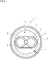
- the pipe 2 and the hot water pipe 4 fastened together by the binding member 5 is disposed at the center in the heat-insulated pipe assembly 1.
- the heat insulating member 3 with the slit 7 surrounds the pipe 2 and the hot water pipe 4.
- the heat insulating member 3 is covered with the protective member 8 covered with the protective member 9.
- the pipe 2 and the hot water pipe 4 may be in close contact with the heat insulating member 3, making the gap 27 small.
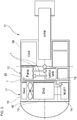
- the heat-insulated pipe assembly 1 is used, for example, in an SCR system 12 of a construction machine 11.
- the construction machine 11 is, for example, a loading shovel or the like used for construction.
- the construction machine 11 includes an engine 13, an exhaust pipe 14, through which an exhaust gas from the engine 13 flows, a radiator 15 releasing heat to the outside, an engine room 17 containing a cooling fan 16 cooling the radiator 15, and a cabin 18 for an operator of the construction machine 11.
- the SCR system 12 is disposed in a space between the cabin 18 at the front of the machine and the engine room 17 at the rear of the machine.
- the engine 13 is connected to the radiator 15 via two pipes not shown in the drawing.
- the pipes are provided with a pump not shown in the drawing so that the antifreeze circulates between the engine 13 and the radiator 15.
- the antifreeze discharged from the radiator 15 is supplied to the engine 13 through the pipes and cools the engine 13.
- the antifreeze heated by cooling the engine 13 is discharged from the engine 13 and supplied to the radiator 15 through the pipes.
- the heated antifreeze is cooled in the radiator 15 and then supplied to the engine 13.
- the engine 13 is cooled by the circulation of the antifreeze between the engine 13 and the radiator 15.
- the SCR system 12 includes the heat-insulated pipe assemblies 1, the exhaust pipe 14, the aqueous urea tank 19, and the pump 20.
- the exhaust pipe 14 includes a spray nozzle (not shown in the drawing). The spray nozzle sprays aqueous urea into the exhaust pipe 14.
- the exhaust pipe 14 further includes an SCR catalyst (not shown in the drawing) downstream of the spray nozzle.
- the pump 20 is connected to the pipes 2 ( FIG. 1 ) of the three heat-insulated pipe assemblies 1.
- the other ends of the pipes 2 of the two heat-insulated pipe assemblies 1 are connected to the aqueous urea tank 19.
- the pump 20 is capable of circulating the aqueous urea between the pump 20 and the aqueous urea tank 19 through the pipes 2.
- the other end of the remaining one of the heat-insulated pipe assemblies 1 is connected to the spray nozzle.
- the pump 20 sucks the aqueous urea from the aqueous urea tank 19 and supplies the aqueous urea to the spray nozzle through the pipe 2.
- the spray nozzle sprays the aqueous urea into the exhaust pipe 14.
- the antifreeze discharged from the engine 13 is supplied to one end of the hot water pipe 4 (see FIG. 1 ) of the heat-insulated pipe assembly 1.
- the antifreeze flows through the hot water pipe 4, and the antifreeze discharged from the other end of the hot water pipe 4 is supplied to the radiator 15.
- the aqueous urea flowing through the pipe 2, which is in contact with the hot water pipe 4 is heated by heat exchange with the antifreeze flowing through the hot water pipe 4.
- the heat-insulated pipe assembly 1 connecting the pump 20 to the spray nozzle is disposed near the engine room 17 at a high ambient temperature.
- the heat-insulated pipe assembly 1 is disposed near the engine 13, which is a heat source, so that the heat-insulated pipe assembly 1 is disposed in an area in a relatively high ambient temperature in the engine room 17. For this reason, the heat-insulated pipe assembly 1 is exposed to external heat at a high temperature.
- the aqueous urea is sprayed to the high-temperature exhaust gas flowing through the exhaust pipe 14.
- the heat of the exhaust gas results in hydrolysis of urea to ammonia.
- the resulting ammonia flows downstream through the exhaust pipe 14 together with the exhaust gas and then reaches the SCR catalyst.
- the SCR catalyst promotes the chemical reaction between ammonia and NOx in the exhaust gas, and NOx is converted into water and nitrogen.
- the heat-insulated pipe assembly 1 includes the pipe 2 allowing the fluid to flow therethrough and a heat insulating member 3 covers at least a part of the pipe 2.
- the pipe 2 is used in the exhaust gas purification system using the SCR catalyst.
- the heat insulating member 3 has a closed-cell structure. Hence, the heat-insulated pipe assembly 1 suppresses an increase in the temperature of the fluid due to the heat exchange with air.
- the heat-insulated pipe assembly 1 is disposed in the area at the high ambient temperature in the engine room 17 and close to the engine 13, the interior of the pipe 2 is thermally insulated from the exterior by the heat insulating member 3. Thereby, the heat-insulated pipe assembly 1 suppresses the increase in the temperature of the aqueous urea, which flows through the pipe 2, due to the heat exchange with air.
- the heat insulating member 3 of the heat-insulated pipe assembly 1 has flexibility and deformed to match the shape of the heat-insulated pipe assembly 1.
- the heat insulating member 3 is capable of securely covering the bent pipe 2.
- the heat-insulated pipe assembly 1 reliably suppresses an increase in the temperature of the aqueous urea flowing through the pipe 2 even when the bent pipe 2 is used.
- the heat insulating member 3 includes the slit 7 extending in the longitudinal direction, and the pipe 2 and the hot water pipe 4 are inserted into the space within the heat insulating member 3 through the slit 7.
- the fabrication of the heat-insulated pipe assembly 1 is facilitated.
- the pipe 2 and the hot water pipe 4 are fastened together by the binding member 5. Thereby, the area of the contact between the surfaces of the pipe 2 and hot water pipe 4 is increased, so that the efficiency of heat exchange between the pipe 2 and the hot water pipe 4 is improved.
- the heat-insulated pipe assembly 1 suppresses the increase in the temperature of the aqueous urea flowing through the pipe 2.
- the pipe 2 and the hot water pipe 4 are fastened together with the binding member 5.
- the present invention is not limited to the above embodiment and various modifications can be made without departing from the scope of the invention.
- the materials and shapes of the pipe 2, the heat insulating member 3, the hot water pipe 4, the binding member 5, the fastening member 10, the joints 6a and 6b, and the protective members 8 and 9 may be changed as appropriate.
- the pipe 2 and the hot water pipe 4 are made from the resin(s) and have flexibility and cylindrical shape(s).
- the present invention is not limited to the above.
- the pipe 2 and the hot water pipe 4 may be made from a material other than the resin and may not have flexibility.
- the pipe 2 and the hot water pipe 4 may have cross-sectional shape(s) other than a circle.
- the heat insulating member 3 is a member having flexibility and has the slit 7 extending in the longitudinal direction.
- the present invention is not limited to this.
- the heat insulating member 3 may not have flexibility and may not have the slit 7.
- the heat-insulated pipe assembly 1 includes the hot water pipe 4.
- the present invention is not limited to this.
- the heat-insulated pipe assembly 1 may not include the hot water pipe 4.
- a heat wire for heating the fluid may be inserted in the pipe 2.
- the heat insulating member 3 is in close contact with the pipe 2, so that the gap 27 within the heat insulating member 3 is small.
- the heat-insulated pipe assembly 1 described in the above embodiment may include a corrugated tube.
- the pipe 2 and the hot water pipe 4 may be covered with the corrugated tube.
- the corrugated tube may be further covered with the heat insulating member 3.
- the heat insulating member 3 covering the pipe 2 and the hot water pipe 4 may be covered with another corrugated tube.
- a portion to be covered by the corrugated tube is not particularly limited.
- the corrugated tube may include a slit extending in the longitudinal direction.
- the gaps 27 inside the heat insulating member 3 increase in number, as compared with the case where the pipe 2 and the hot water pipe 4 are directly covered with the heat insulating member 3.
- the heat insulating member 3 of the heat-insulated pipe assembly 1 is covered with the protective member 8 and the protective member 9.
- the present invention is not limited to this.
- the heat insulating member 3 may be covered only with the protective member 8 or only with the protective member 9.
- the heat insulating member 3 may not be covered with any protective member.
- the heat insulating member 3 may include a closing member not shown in the drawing.
- the closing member covers a part of the surface of the heat insulating member 3, and secures the heat insulating member 3 to prevent the slit 7 from opening. Hence, the heat insulating member 3 is secured such that most of the slit 7 is closed.
- the closing member may be, for example, a tape-shaped member (the same member as the protective member 9) having high elasticity, adhesion, and heat resistance.
- the closing members may be attached to two or more portions of the surface of the heat insulating member 3 such that the closing members intersect the slit 7, thereby securing the slit 7 closed.
- the closing member may be attached to the surface of the heat insulating member 3, to cover the entire slit 7.
- the closing member secures the heat insulating member 3 to close the slit 7.
- the heat insulating member 3 securely covers the pipe 2.
- the heat-insulated pipe assembly 1 more reliably suppresses the increase in the temperature of the aqueous urea flowing through the pipe 2.
- the heat-insulated pipe assemblies 1 according to Examples 1 to 6 were fabricated. Table 1 shows the shapes of cross-sections of the heat-insulated pipe assemblies 1 of Examples 1 to 6.
- the pipe 2 with the length of 1 m includes joints disposed at the respective ends.
- the pipe 2 is covered with the heat insulating member 3 with the length of 0.95 m or the like.
- the heat-insulated pipe assembly 1 was fabricated using the following: a resin tube (model number: TEU-4-8x6) was used as the pipe 2; an Aeroflex insulation tube (model number: M10010 for Examples 1 and 3 to 6, and model number: M10016 for Example 2) with the slit 7 was used as the heat insulating member 3; and tesa tape (model number: 51026) having high heat resistance was used as the protective member 8.
- a resin tube model number: TEU-4-8x6
- Aeroflex insulation tube model number: M10010 for Examples 1 and 3 to 6, and model number: M10016 for Example 2
- tesa tape model number: 51026
- Example 2 the pipe 2 was covered with a corrugated tube 21 (size: 10) having a slit 22. The corrugated tube 21 was then covered with the heat insulating member 3. Thus, the heat-insulated pipe assembly 1 was fabricated.
- Example 3 the pipe 2 was covered with the heat insulating member 3. The heat insulating member 3 was then covered with a corrugated tube 21 (size: 28) having a slit 22. Thus, the heat-insulated pipe assembly 1 was fabricated.
- Example 5 the fabricated heat-insulated pipe assembly 1 was left in a constant temperature bath at 120°C for 24 hours, to be subjected to heat treatment.
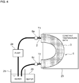
- the heat insulation performances of the heat-insulated pipe assemblies 1 according to Examples 1 to 6 were evaluated in the following manner. As shown in FIG. 4 , the heat-insulated pipe assembly 1 was disposed such that approximately the entire heat insulating member 3 was accommodated inside a constant temperature bath 23 and the temperature in the constant temperature bath 23 was then increased to 80°C. Subsequently, with the pump 24 at the flow rate of 24 mL/min, water in the water tank 25 was supplied to the joint 6a of the heat-insulated pipe assembly 1 and water discharged from a joint 6c was returned to the water tank 25. Thus, the water is circulated.
- the temperature of the heater 26 was adjusted to heat the water, to maintain the temperature (hereinafter referred to as inlet temperature) of the pipe 2 exposed externally at approximately 40°C at a location T1 between the joint 6a and the heat insulating member 3 disposed in the constant temperature bath 23.
- inlet temperature the temperature (hereinafter referred to as inlet temperature) of the pipe 2 exposed externally at approximately 40°C at a location T1 between the joint 6a and the heat insulating member 3 disposed in the constant temperature bath 23.
- the temperature (hereinafter referred to as outlet temperature) of the pipe 2 exposed externally at a location T2 between the joint 6c and the heat insulating member 3 was measured.
- the heat insulation performance of the heat-insulated pipe assembly 1 was evaluated based on a difference between the measured outlet temperature and the measured inlet temperature. Smaller the difference, higher the heat insulation performance of the heat-insulated pipe assembly 1.
- the comparison among the heat-insulated pipe assemblies 1 according to Examples 1 to 6 and the pipes according to Comparative examples 1 and 2 shows that the temperature differences of the heat-insulated pipe assemblies 1 according to Examples 1 to 6 are smaller than those of the pipes according to Comparative examples 1 and 2.
- the heat-insulated pipe assembly 1 including the heat insulating member 3 with the closed-cell structure has high heat insulation performance.
- the heat-insulated pipe assembly 1 of the present invention suppresses the increase in the temperature of the fluid flowing through the pipe 2 due to the heat exchange with air.
- Comparative example 2 including the corrugated tube 21 has a temperature difference smaller than that of Comparative example 1. This demonstrates that the corrugated tube 21 provides heat insulating effects. However, since the temperature difference of Comparative example 2 is larger than the temperature difference of the heat-insulated pipe assembly according to Example 1, the heat insulation performance of the corrugated tube 21 is not adequate.
- a comparison between the heat-insulated pipe assembly 1 according to Example 1 and the heat-insulated pipe assemblies 1 according to Examples 2 and 3 including the corrugated tube 21 shows that the temperature differences of the heat-insulated pipe assemblies 1 according to Examples 2 and 3 are similar to that of Example 1. This shows that the corrugated tube 21 in the heat-insulated pipe assembly 1 does not provide additional heat insulating effects but the heat insulating member 3 provides high heat insulation performance.
- the heat-insulated pipe assembly 1 according to Example 5 has a temperature difference similar to that of the heat-insulated pipe assembly 1 according to Example 1.
- the heat-insulated pipe assembly 1 according to Example 5 maintains high heat insulation performance despite the shrinkage of the heat insulating member 3 due to the heat treatment.
- the heat-insulated pipe assembly 1 was subjected to a long-time heat resistance test.
- the heat resistance property of the heat-insulated pipe assembly 1 was evaluated by a comparison between heat insulation performances before and after the heat resistance test.
- the heat insulation performance was evaluated in the same manner as in the above-explained method.
- the heat-insulated pipe assembly 1 used in the heat resistance test was fabricated as follows: a resin tube (TEU-4-8x6), which was used as the pipe 2, was covered by Aeroflex (model number: M10010) with a slit, which was used as the heat insulating member 3. Then, tesa tape (model number: 51026), which was used as the protective member 8, and Irrax tape VZL having heat resistance property, which was used as a protective member 9, were wrapped around in this order. Three heat-insulated pipe assemblies 1 (samples A, B, and C) having the same configuration were fabricated. Heat resistance properties of the three heat-insulated pipe assemblies 1 were evaluated.
- the heat-insulated pipe assemblies 1 of the samples A, B, and C exhibit similar temperature differences before and after the heat resistance test, and maintain high heat insulation. This shows that the heat-insulated pipe assemblies 1 have heat resistance.
Abstract
Description
- The present invention relates to a heat-insulated pipe assembly.
- Vehicles and the like including a diesel engine that emits nitrogen oxides (hereinafter referred to as NOx) employ an exhaust gas purification system (hereinafter referred to as SCR system) using a selective catalytic reduction (SCR) catalyst to remove NOx. The SCR system includes a spray nozzle and the SCR catalyst. The spray nozzle sprays aqueous urea into an exhaust pipe, in which an exhaust gas from the engine flows. The SCR catalyst is disposed downstream of the spray nozzle. In the SCR system, the aqueous urea is sprayed to a high-temperature exhaust gas flowing through the exhaust pipe upon the discharge of exhaust gas from the engine to the exhaust pipe. The heat of the exhaust gas results in hydrolysis of urea to ammonia. The resulting ammonia flows downstream through the exhaust pipe together with the exhaust gas and then reaches the SCR catalyst. The SCR catalyst promotes the chemical reaction between ammonia and NOx in the exhaust gas, and NOx is converted into water and nitrogen.
- In the SCR system, the spray nozzle is connected to an aqueous urea tank through a pipe, and the aqueous urea in the tank is supplied to the spray nozzle through the pipe as appropriate. In the SCR system, however, since the freezing point of the aqueous urea is approximately -11°C, the aqueous urea in the pipe is frozen and cannot be supplied to the spray nozzle in cold climate areas. To solve this problem, a technique that prevents freezing of the aqueous urea in the pipe has been developed. For example,
Patent Literature 1 discloses a liquid transporting pipe in which a connecting portion between a pipe joint and a pipe and a pipe adjacent to the connecting portion are covered by a dissipation preventing cover, and a cord heater is inserted in the pipe. - Patent Literature 1:
Japanese Patent Laid-Open No. 2009-250271 - Since the exhaust pipe is disposed close to the engine, which emits heat of high temperature, an ambient temperature around the pipe connected to the exhaust pipe is very high. Accordingly, the temperature of the aqueous urea in the pipe increases due to heat exchange with air and exceeds an allowable level, causing evaporation and too high concentration, which may produce ammonia. To solve this problem, in conventional methods, a heat shield plate has been disposed between the pipe and a heat source to suppress the increase in the temperature of the aqueous urea but has not been effective.
- In view of the foregoing problems, an object of the present invention is to provide a heat-insulated pipe assembly capable of suppressing an increase in a temperature in a pipe due to heat exchange with air.
- A heat-insulated pipe assembly of the present invention includes a pipe allowing a fluid to flow therethrough and a heat insulating member covers at least a part of the pipe. The pipe is used in an exhaust gas purification system using an SCR catalyst. The heat insulating member has a closed-cell structure and is configured to suppress an increase in a temperature of the fluid due to heat exchange with air.
- The heat-insulated pipe assembly of the present invention includes the pipe allowing a fluid to flow therethrough and the heat insulating member covers at least a part of the pipe. The pipe is used in the exhaust gas purification system using the SCR catalyst, and the heat insulating member has the closed-cell structure and is configured to suppress the increase in the temperature of the fluid due to the heat exchange with air. Hence, in the exhaust gas purification system using the SCR catalyst, the interior of the pipe is thermally insulated from the exterior by the heat insulating member. Thereby, the increase in the temperature of the fluid flowing through the pipe due to heat exchange with air is suppressed.
-
-
FIG. 1 is a partial perspective view showing the entire structure of a heat-insulated pipe assembly according to an embodiment of the present invention. -
FIG. 2 is an end view of a heat-insulated pipe assembly according to an embodiment of the present invention along line A-A' inFIG. 1 . -
FIG. 3 is a schematic view of a construction machine using a heat-insulated pipe assembly according to an embodiment of the present invention. -
FIG. 4 is a schematic view of a device for evaluating the heat insulation performance of a heat-insulated pipe assembly according to an embodiment of the present invention. - The heat-insulated
pipe assembly 1 shown inFIG. 1 includes apipe 2 allowing a fluid to flow therethrough, and aheat insulating member 3 covering at least a part of thepipe 2. The heat-insulatedpipe assembly 1 further includes a hot water pipe 4. The hot water pipe 4 is disposed along thepipe 2. The hot water pipe 4 allows the heated fluid to flow therethrough. Thepipe 2 and the hot water pipe 4 have flexibility and have cylindrical shape(s). Material(s) of thepipe 2 and the hot water pipe 4 is selected in accordance with the liquids flowing therethrough. The material of thepipe 2 is selected to allow aqueous urea, being the fluid, to flow through thepipe 2. The material of the hot water pipe 4 is selected to allow an antifreeze, being the heated fluid, to flow through the hot water pipe 4. In this embodiment, thepipe 2 and the hot water pipe 4 are made from resin(s). - The
pipe 2 and the hot water pipe 4 are fastened together by a bindingmember 5 such that their surfaces come into contact with each other. In this embodiment, thebinding member 5 is a tape-shaped member helically and closely wrapped around the surfaces of thepipe 2 and the hot water pipe 4 with their surfaces in contact with each other, thereby fastening thepipe 2 and the hot water pipe 4 together. In this embodiment, the tape-shaped member is not adhesive. The tape-shaped member may be adhesive. - The
pipe 2 includes ajoint 6a at one end and another joint, which is not shown in the drawing, at the other end. The joint 6a facilitates connection to a unit. Similarly, the hot water pipe 4 has ajoint 6b at one end and another joint, which is not shown in the drawing, at the other end. In this embodiment, thejoints pipe 2 and the hot water pipe 4 may have a joint only at one end or may have no joints. - The
heat insulating member 3 is composed of a member having a closed-cell structure and which has flexibility like elastomer, for example. In the closed-cell structure, adjacent foams are not connected to each other and a plurality of foams are independent from each other. Theheat insulating member 3 is formed from, for example, an ethylene propylene diene-based synthetic rubber, a nitrile-based synthetic rubber, or the like. Theheat insulating member 3 has a hollow cylindrical shape. Thepipe 2 and the hot water pipe 4 are inserted into and disposed in the hollow portion of theheat insulating member 3 so that theheat insulating member 3 covers at least a part of thepipe 2 and at least a part of the hot water pipe 4. Theheat insulating member 3 includes aslit 7 extending in a longitudinal direction. Thepipe 2 and the hot water pipe 4 are inserted into the inside through theslit 7. - The
heat insulating member 3 is covered with aprotective member 8 having abrasion resistance for protection from external impact. In this embodiment, theprotective member 8 is a tape-shaped member having high heat resistance and abrasion resistance, and helically and closely wrapped around the surface of theheat insulating member 3. Thus, theprotective member 8 protects theheat insulating member 3 from an external impact, thereby suppressing the deterioration of the heat insulation performance of theheat insulating member 3 due to an external impact. - The
protective member 8 covering the surface of theheat insulating member 3 is covered with aprotective member 9. Theprotective member 9 has elastic and adhesive properties. In this embodiment, theprotective member 9 is a tape-shaped member having high elasticity, adhesion, and heat resistance. Theprotective member 9 is helically and closely wrapped around the surface of theprotective member 8. Consequently, theprotective member 8 is fastened with theprotective member 9, so that peeling of theprotective member 8 is suppressed. Thus, theheat insulating member 3 is protected from an external impact, and a reduction in heat insulation performance of theheat insulating member 3 is prevented. - The
protective members protective members pipe assembly 1 improves. The heat-insulatedpipe assembly 1 suppresses a reduction in the heat insulation performance in the high temperature atmosphere. An increase in the temperature of the fluid flowing through thepipe 2 is suppressed more reliably. - In this embodiment, the
protective members protective members protective members heat insulating member 3. For example, theprotective members - As shown in
FIG. 1 , one end of theheat insulating member 3 is fixed to thepipe 2 and the hot water pipe 4 with afastening member 10, and so is the other end (not shown) of theheat insulating member 3. In this embodiment, thefastening member 10 is an adhesive tape-shaped member and helically and closely wrapped around each of the ends of theheat insulating member 3, thereby fixing theheat insulating member 3 to thepipe 2 and the hot water pipe 4. - As shown in
FIG. 2 , thepipe 2 and the hot water pipe 4 fastened together by the bindingmember 5 is disposed at the center in the heat-insulatedpipe assembly 1. Theheat insulating member 3 with theslit 7 surrounds thepipe 2 and the hot water pipe 4. In the heat-insulatedpipe assembly 1, theheat insulating member 3 is covered with theprotective member 8 covered with theprotective member 9. In this embodiment, there is agap 27 between thepipe 2 and the hot water pipe 4 fastened together and theheat insulating member 3. Thepipe 2 and the hot water pipe 4 may be in close contact with theheat insulating member 3, making thegap 27 small. - As shown in
FIG. 3 , the heat-insulatedpipe assembly 1 is used, for example, in anSCR system 12 of aconstruction machine 11. Theconstruction machine 11 is, for example, a loading shovel or the like used for construction. Theconstruction machine 11 includes anengine 13, anexhaust pipe 14, through which an exhaust gas from theengine 13 flows, aradiator 15 releasing heat to the outside, anengine room 17 containing a coolingfan 16 cooling theradiator 15, and acabin 18 for an operator of theconstruction machine 11. TheSCR system 12 is disposed in a space between thecabin 18 at the front of the machine and theengine room 17 at the rear of the machine. - The
engine 13 is connected to theradiator 15 via two pipes not shown in the drawing. The pipes are provided with a pump not shown in the drawing so that the antifreeze circulates between theengine 13 and theradiator 15. With the use of the pump, the antifreeze discharged from theradiator 15 is supplied to theengine 13 through the pipes and cools theengine 13. The antifreeze heated by cooling theengine 13 is discharged from theengine 13 and supplied to theradiator 15 through the pipes. The heated antifreeze is cooled in theradiator 15 and then supplied to theengine 13. Thus, theengine 13 is cooled by the circulation of the antifreeze between theengine 13 and theradiator 15. - The
SCR system 12 includes the heat-insulatedpipe assemblies 1, theexhaust pipe 14, theaqueous urea tank 19, and thepump 20. Theexhaust pipe 14 includes a spray nozzle (not shown in the drawing). The spray nozzle sprays aqueous urea into theexhaust pipe 14. Theexhaust pipe 14 further includes an SCR catalyst (not shown in the drawing) downstream of the spray nozzle. Thepump 20 is connected to the pipes 2 (FIG. 1 ) of the three heat-insulatedpipe assemblies 1. The other ends of thepipes 2 of the two heat-insulatedpipe assemblies 1 are connected to theaqueous urea tank 19. Hence, thepump 20 is capable of circulating the aqueous urea between thepump 20 and theaqueous urea tank 19 through thepipes 2. The other end of the remaining one of the heat-insulatedpipe assemblies 1 is connected to the spray nozzle. Hence, thepump 20 sucks the aqueous urea from theaqueous urea tank 19 and supplies the aqueous urea to the spray nozzle through thepipe 2. The spray nozzle sprays the aqueous urea into theexhaust pipe 14. - In the
SCR system 12, the antifreeze discharged from theengine 13 is supplied to one end of the hot water pipe 4 (seeFIG. 1 ) of the heat-insulatedpipe assembly 1. The antifreeze flows through the hot water pipe 4, and the antifreeze discharged from the other end of the hot water pipe 4 is supplied to theradiator 15. Hence, in theSCR system 12, the aqueous urea flowing through thepipe 2, which is in contact with the hot water pipe 4, is heated by heat exchange with the antifreeze flowing through the hot water pipe 4. - In the
SCR system 12, the heat-insulatedpipe assembly 1 connecting thepump 20 to the spray nozzle is disposed near theengine room 17 at a high ambient temperature. Specifically, the heat-insulatedpipe assembly 1 is disposed near theengine 13, which is a heat source, so that the heat-insulatedpipe assembly 1 is disposed in an area in a relatively high ambient temperature in theengine room 17. For this reason, the heat-insulatedpipe assembly 1 is exposed to external heat at a high temperature. - In this
SCR system 12, the aqueous urea is sprayed to the high-temperature exhaust gas flowing through theexhaust pipe 14. The heat of the exhaust gas results in hydrolysis of urea to ammonia. The resulting ammonia flows downstream through theexhaust pipe 14 together with the exhaust gas and then reaches the SCR catalyst. The SCR catalyst promotes the chemical reaction between ammonia and NOx in the exhaust gas, and NOx is converted into water and nitrogen. - In the above configuration, the heat-insulated
pipe assembly 1 according to the embodiment of the present invention includes thepipe 2 allowing the fluid to flow therethrough and aheat insulating member 3 covers at least a part of thepipe 2. Thepipe 2 is used in the exhaust gas purification system using the SCR catalyst. Theheat insulating member 3 has a closed-cell structure. Hence, the heat-insulatedpipe assembly 1 suppresses an increase in the temperature of the fluid due to the heat exchange with air. - Even when the heat-insulated
pipe assembly 1 is disposed in the area at the high ambient temperature in theengine room 17 and close to theengine 13, the interior of thepipe 2 is thermally insulated from the exterior by theheat insulating member 3. Thereby, the heat-insulatedpipe assembly 1 suppresses the increase in the temperature of the aqueous urea, which flows through thepipe 2, due to the heat exchange with air. - The
heat insulating member 3 of the heat-insulatedpipe assembly 1 has flexibility and deformed to match the shape of the heat-insulatedpipe assembly 1. Theheat insulating member 3 is capable of securely covering thebent pipe 2. Thus, the heat-insulatedpipe assembly 1 reliably suppresses an increase in the temperature of the aqueous urea flowing through thepipe 2 even when thebent pipe 2 is used. - In the heat-insulated
pipe assembly 1, theheat insulating member 3 includes theslit 7 extending in the longitudinal direction, and thepipe 2 and the hot water pipe 4 are inserted into the space within theheat insulating member 3 through theslit 7. Thus, the fabrication of the heat-insulatedpipe assembly 1 is facilitated. - In the heat-insulated
pipe assembly 1, thepipe 2 and the hot water pipe 4 are fastened together by the bindingmember 5. Thereby, the area of the contact between the surfaces of thepipe 2 and hot water pipe 4 is increased, so that the efficiency of heat exchange between thepipe 2 and the hot water pipe 4 is improved. Thus, the heat-insulatedpipe assembly 1 suppresses the increase in the temperature of the aqueous urea flowing through thepipe 2. In the heat-insulatedpipe assembly 1, thepipe 2 and the hot water pipe 4 are fastened together with the bindingmember 5. Hence, it is easy to cover thepipe 2 and the hot water pipe 4 with theheat insulating member 3, facilitating the fabrication of the heat-insulatedpipe assembly 1. - The present invention is not limited to the above embodiment and various modifications can be made without departing from the scope of the invention. For example, the materials and shapes of the
pipe 2, theheat insulating member 3, the hot water pipe 4, the bindingmember 5, thefastening member 10, thejoints protective members - In the above embodiment, the
pipe 2 and the hot water pipe 4 are made from the resin(s) and have flexibility and cylindrical shape(s). The present invention is not limited to the above. Thepipe 2 and the hot water pipe 4 may be made from a material other than the resin and may not have flexibility. Thepipe 2 and the hot water pipe 4 may have cross-sectional shape(s) other than a circle. - In the above embodiment, the
heat insulating member 3 is a member having flexibility and has theslit 7 extending in the longitudinal direction. The present invention is not limited to this. Theheat insulating member 3 may not have flexibility and may not have theslit 7. - In the above embodiment, the heat-insulated
pipe assembly 1 includes the hot water pipe 4. The present invention is not limited to this. The heat-insulatedpipe assembly 1 may not include the hot water pipe 4. Instead of the hot water pipe 4, a heat wire for heating the fluid may be inserted in thepipe 2. In a case where the heat-insulatedpipe assembly 1 does not include the hot water pipe 4, theheat insulating member 3 is in close contact with thepipe 2, so that thegap 27 within theheat insulating member 3 is small. - The heat-insulated
pipe assembly 1 described in the above embodiment may include a corrugated tube. For example, thepipe 2 and the hot water pipe 4 may be covered with the corrugated tube. The corrugated tube may be further covered with theheat insulating member 3. Theheat insulating member 3 covering thepipe 2 and the hot water pipe 4 may be covered with another corrugated tube. A portion to be covered by the corrugated tube is not particularly limited. The corrugated tube may include a slit extending in the longitudinal direction. In a case where thepipe 2 and the hot water pipe 4 are covered with the corrugated tube and the corrugated tube is covered with theheat insulating member 3, thegaps 27 inside theheat insulating member 3 increase in number, as compared with the case where thepipe 2 and the hot water pipe 4 are directly covered with theheat insulating member 3. - In the above embodiment, the
heat insulating member 3 of the heat-insulatedpipe assembly 1 is covered with theprotective member 8 and theprotective member 9. The present invention is not limited to this. Theheat insulating member 3 may be covered only with theprotective member 8 or only with theprotective member 9. Theheat insulating member 3 may not be covered with any protective member. - The
heat insulating member 3 may include a closing member not shown in the drawing. The closing member covers a part of the surface of theheat insulating member 3, and secures theheat insulating member 3 to prevent theslit 7 from opening. Hence, theheat insulating member 3 is secured such that most of theslit 7 is closed. The closing member may be, for example, a tape-shaped member (the same member as the protective member 9) having high elasticity, adhesion, and heat resistance. In this case, for example, the closing members may be attached to two or more portions of the surface of theheat insulating member 3 such that the closing members intersect theslit 7, thereby securing theslit 7 closed. The closing member may be attached to the surface of theheat insulating member 3, to cover theentire slit 7. - In the heat-insulated
pipe assembly 1, the closing member secures theheat insulating member 3 to close theslit 7. Thereby, theheat insulating member 3 securely covers thepipe 2. Hence, the heat-insulatedpipe assembly 1 more reliably suppresses the increase in the temperature of the aqueous urea flowing through thepipe 2. - To evaluate the heat insulation performance of the heat-insulated
pipe assemblies 1, the heat-insulatedpipe assemblies 1 according to Examples 1 to 6 were fabricated. Table 1 shows the shapes of cross-sections of the heat-insulatedpipe assemblies 1 of Examples 1 to 6. In each of the heat-insulatedpipe assemblies 1 fabricated according to Examples 1 to 6, thepipe 2 with the length of 1 m includes joints disposed at the respective ends. Thepipe 2 is covered with theheat insulating member 3 with the length of 0.95 m or the like. The heat-insulatedpipe assembly 1 was fabricated using the following: a resin tube (model number: TEU-4-8x6) was used as thepipe 2; an Aeroflex insulation tube (model number: M10010 for Examples 1 and 3 to 6, and model number: M10016 for Example 2) with theslit 7 was used as theheat insulating member 3; and tesa tape (model number: 51026) having high heat resistance was used as theprotective member 8.[Table 1] Example 1 Example 2 Example 3 Example 4 Example 5 Example 6 Comparative Example 1 Comparative Example 2 Temperature difference (°C) 1.8 1.8 2.0 1.4 1.5 1.6 10.3 8.9 Outermost diameter (mm) 31 37 34 28 28 26 8 14 Cross section 


- In Example 2, the
pipe 2 was covered with a corrugated tube 21 (size: 10) having a slit 22. The corrugated tube 21 was then covered with theheat insulating member 3. Thus, the heat-insulatedpipe assembly 1 was fabricated. - In Example 3, the
pipe 2 was covered with theheat insulating member 3. Theheat insulating member 3 was then covered with a corrugated tube 21 (size: 28) having a slit 22. Thus, the heat-insulatedpipe assembly 1 was fabricated. - In Examples 5 and 6, the fabricated heat-insulated
pipe assembly 1 was left in a constant temperature bath at 120°C for 24 hours, to be subjected to heat treatment. - The heat insulation performances of the heat-insulated
pipe assemblies 1 according to Examples 1 to 6 were evaluated in the following manner. As shown inFIG. 4 , the heat-insulatedpipe assembly 1 was disposed such that approximately the entireheat insulating member 3 was accommodated inside aconstant temperature bath 23 and the temperature in theconstant temperature bath 23 was then increased to 80°C. Subsequently, with thepump 24 at the flow rate of 24 mL/min, water in thewater tank 25 was supplied to the joint 6a of the heat-insulatedpipe assembly 1 and water discharged from a joint 6c was returned to thewater tank 25. Thus, the water is circulated. Afterwards, the temperature of theheater 26 was adjusted to heat the water, to maintain the temperature (hereinafter referred to as inlet temperature) of thepipe 2 exposed externally at approximately 40°C at a location T1 between the joint 6a and theheat insulating member 3 disposed in theconstant temperature bath 23. After the inlet temperature is stable at approximately 40°C, the temperature (hereinafter referred to as outlet temperature) of thepipe 2 exposed externally at a location T2 between the joint 6c and theheat insulating member 3 was measured. The heat insulation performance of the heat-insulatedpipe assembly 1 was evaluated based on a difference between the measured outlet temperature and the measured inlet temperature. Smaller the difference, higher the heat insulation performance of the heat-insulatedpipe assembly 1. - For comparison, pipes of Comparative Examples 1 and 2 are fabricated. In Comparative Example 1, a pipe consisting only of a resin tube (model number: TEU-4-8x6) was used instead of the heat-insulated
pipe assembly 1. In Comparative example 2, a pipe consisting of the resin tube (model number: TEU-4-8x6) covered with the corrugated tube 21 (size: 10) having the slit 22 was fabricated. The heat insulation performances of the pipes of the Comparative Examples 1 and 2 were evaluated in the same manner as the above. The evaluation is shown in "temperature difference (°C)" in Table 1. - The comparison among the heat-insulated
pipe assemblies 1 according to Examples 1 to 6 and the pipes according to Comparative examples 1 and 2 shows that the temperature differences of the heat-insulatedpipe assemblies 1 according to Examples 1 to 6 are smaller than those of the pipes according to Comparative examples 1 and 2. This means that the heat-insulatedpipe assembly 1 including theheat insulating member 3 with the closed-cell structure has high heat insulation performance. Thus, it was verified that the heat-insulatedpipe assembly 1 of the present invention suppresses the increase in the temperature of the fluid flowing through thepipe 2 due to the heat exchange with air. - The comparison between the pipe of Comparative example 1 and the pipe of Comparative example 2 shows that Comparative example 2 including the corrugated tube 21 has a temperature difference smaller than that of Comparative example 1. This demonstrates that the corrugated tube 21 provides heat insulating effects. However, since the temperature difference of Comparative example 2 is larger than the temperature difference of the heat-insulated pipe assembly according to Example 1, the heat insulation performance of the corrugated tube 21 is not adequate.
- A comparison between the heat-insulated
pipe assembly 1 according to Example 1 and the heat-insulatedpipe assemblies 1 according to Examples 2 and 3 including the corrugated tube 21 shows that the temperature differences of the heat-insulatedpipe assemblies 1 according to Examples 2 and 3 are similar to that of Example 1. This shows that the corrugated tube 21 in the heat-insulatedpipe assembly 1 does not provide additional heat insulating effects but theheat insulating member 3 provides high heat insulation performance. - A comparison between the heat-insulated
pipe assembly 1 according to Example 1 and the heat-insulatedpipe assembly 1 according to Example 5, which includes heat treatment, shows that the heat-insulatedpipe assembly 1 according to Example 5 has a small outermost diameter. This is due to shrinkage of theheat insulating member 3. The heat-insulatedpipe assembly 1 according to Example 5 has a temperature difference similar to that of the heat-insulatedpipe assembly 1 according to Example 1. The heat-insulatedpipe assembly 1 according to Example 5 maintains high heat insulation performance despite the shrinkage of theheat insulating member 3 due to the heat treatment. Similarly, a comparison between the heat-insulatedpipe assembly 1 according to Example 4 and the heat-insulatedpipe assembly 1 according to Example 6, which includes heat treatment, shows that the heat-insulatedpipe assembly 1 according to Example 6 has a small outermost diameter due to shrinkage, but the temperature difference of the heat-insulatedpipe assembly 1 according to Example 6 is similar to that of the heat-insulated pipe assembly according to Example 4. Thus, the heat-insulatedpipe assembly 1 according to Example 6 maintains high heat insulation performance. - To further examine the heat resistance property of the heat-insulated
pipe assembly 1, the heat-insulatedpipe assembly 1 was subjected to a long-time heat resistance test. The heat resistance property of the heat-insulatedpipe assembly 1 was evaluated by a comparison between heat insulation performances before and after the heat resistance test. The heat insulation performance was evaluated in the same manner as in the above-explained method. - The heat-insulated
pipe assembly 1 used in the heat resistance test was fabricated as follows: a resin tube (TEU-4-8x6), which was used as thepipe 2, was covered by Aeroflex (model number: M10010) with a slit, which was used as theheat insulating member 3. Then, tesa tape (model number: 51026), which was used as theprotective member 8, and Irrax tape VZL having heat resistance property, which was used as aprotective member 9, were wrapped around in this order. Three heat-insulated pipe assemblies 1 (samples A, B, and C) having the same configuration were fabricated. Heat resistance properties of the three heat-insulatedpipe assemblies 1 were evaluated. - First, the heat insulation performance of each of the heat-insulated
pipe assemblies 1 before the heat resistance test was evaluated by the method described above. Then, the three heat-insulatedpipe assemblies 1 were left in a constant temperature bath at 110°C for 1000 hours. Thus, the heat resistance tests of the three heat-insulatedpipe assemblies 1 were performed. Finally, the heat insulation performance of each of the heat-insulatedpipe assemblies 1 after the heat resistance test was evaluated by the method described above. Table 2 shows the results. Since temperature differences of the samples A, B, and C before the heat resistance test were the same, Table 2 collectively shows the results in "Before test".[Table 2] Before test After heat resistance test Sample A Sample B Sample C Inlet temperature (°C) 40.0 40.0 40.0 40.0 Outlet temperature (°C) 41.4 41.9 41.4 41.9 Temperature difference (°C) 1.4 1.9 1.4 1.9 - As shown in Table 2, the heat-insulated
pipe assemblies 1 of the samples A, B, and C exhibit similar temperature differences before and after the heat resistance test, and maintain high heat insulation. This shows that the heat-insulatedpipe assemblies 1 have heat resistance. -
- 1 heat-insulated pipe assembly
- 2 pipe
- 3 heat insulating member
- 4 hot water pipe
- 5 binding member
- 6a, 6b, 6c joint
- 7 slit
- 8, 9 protective member
- 10 fastening member
Claims (7)
- A heat-insulated pipe assembly comprising:a pipe allowing a fluid to flow therethrough; anda heat insulating member covering at least a part of the pipe, whereinthe pipe is used in an exhaust gas purification system using an SCR catalyst, andthe heat insulating member has a closed-cell structure and is configured to suppress an increase in a temperature of the fluid due to heat exchange with air.
- The heat-insulated pipe assembly according to claim 1, wherein the heat insulating member has flexibility.
- The heat-insulated pipe assembly according to claim 1 or 2, wherein the heat insulating member has a slit extending in a longitudinal direction.
- The heat-insulated pipe assembly according to claim 3, wherein the heat insulating member is secured with a closing member such that the slit is closed by the closing member.
- The heat-insulated pipe assembly according to any one of claims 1 to 4, wherein the pipe includes at least one joint at an end of the pipe.
- The heat-insulated pipe assembly according to any one of claims 1 to 5, further comprising a hot water pipe, the hot water pipe being in contact with the pipe, the hot water pipe allowing a heated fluid to flow therethrough.
- The heat-insulated pipe assembly according to claim 6, wherein the pipe and the hot water pipe are fastened with a binding member.
Applications Claiming Priority (2)
| Application Number | Priority Date | Filing Date | Title |
|---|---|---|---|
| JP2014200983A JP2016070189A (en) | 2014-09-30 | 2014-09-30 | Adiabatic pipe |
| PCT/JP2015/075994 WO2016052156A1 (en) | 2014-09-30 | 2015-09-14 | Heat-insulated pipe arrangement |
Publications (2)
| Publication Number | Publication Date |
|---|---|
| EP3203046A1 true EP3203046A1 (en) | 2017-08-09 |
| EP3203046A4 EP3203046A4 (en) | 2018-03-07 |
Family
ID=55630198
Family Applications (1)
| Application Number | Title | Priority Date | Filing Date |
|---|---|---|---|
| EP15847946.9A Withdrawn EP3203046A4 (en) | 2014-09-30 | 2015-09-14 | Heat-insulated pipe arrangement |
Country Status (6)
| Country | Link |
|---|---|
| US (1) | US10428995B2 (en) |
| EP (1) | EP3203046A4 (en) |
| JP (1) | JP2016070189A (en) |
| KR (1) | KR20170061151A (en) |
| CN (1) | CN106715852A (en) |
| WO (1) | WO2016052156A1 (en) |
Cited By (1)
| Publication number | Priority date | Publication date | Assignee | Title |
|---|---|---|---|---|
| IT201800006074A1 (en) * | 2018-06-06 | 2019-12-06 | DUCT FOR A FLUID TO BE TRANSPORTED, PARTICULARLY IN A MOTOR VEHICLE. |
Families Citing this family (1)
| Publication number | Priority date | Publication date | Assignee | Title |
|---|---|---|---|---|
| CN112628461B (en) * | 2020-12-21 | 2022-11-08 | 宁津美华工业有限公司 | Special valve for liquid conveying |
Family Cites Families (25)
| Publication number | Priority date | Publication date | Assignee | Title |
|---|---|---|---|---|
| US3557840A (en) * | 1968-05-09 | 1971-01-26 | Atlas Chem Ind | Cellular plastic foam insulation board structures |
| US3602636A (en) * | 1969-11-06 | 1971-08-31 | Reynolds Metals Co | Wrapped service entrance cable |
| US3633630A (en) * | 1970-03-17 | 1972-01-11 | Dow Chemical Co | Conduit insulation |
| US3853149A (en) * | 1970-05-14 | 1974-12-10 | Moore & Co Samuel | Composite tubing |
| US3757031A (en) * | 1972-05-02 | 1973-09-04 | Thomas & Betts Corp | The like selectively closable protective enclosure for electrical splices and |
| US4399319A (en) * | 1981-11-18 | 1983-08-16 | Bio-Energy Systems, Inc. | Thermally insulated composite flexible hose |
| US4713271A (en) * | 1982-06-30 | 1987-12-15 | Cosden Technology, Inc. | Foamed polymer tubing |
| JPH0246394A (en) * | 1988-08-04 | 1990-02-15 | Furukawa Electric Co Ltd:The | Penetrating pipeline structure for fire retarding division of refrigerant pipe |
| US5421371A (en) * | 1993-04-19 | 1995-06-06 | Nmc Of North America, Inc. | Multi-layered bonded closure system for foam tubes or profiles |
| JP2593199Y2 (en) * | 1993-06-28 | 1999-04-05 | 株式会社クボタ | Insulated tube with leak detection line |
| US5400602A (en) * | 1993-07-08 | 1995-03-28 | Cryomedical Sciences, Inc. | Cryogenic transport hose |
| PL176014B1 (en) * | 1994-01-14 | 1999-03-31 | Rockwool Int | Method of and apparatus for applying insulation |
| JP3391664B2 (en) * | 1997-07-23 | 2003-03-31 | 早川ゴム株式会社 | Soundproof structure of water supply pipe or hot water supply pipe |
| JP4151938B2 (en) * | 2001-12-27 | 2008-09-17 | 株式会社イノアックコーポレーション | Insulating material for bent pipe and method for manufacturing the insulating material for bent pipe |
| JP4457305B2 (en) * | 2005-03-29 | 2010-04-28 | 日本ポリウレタン工業株式会社 | Manufacturing method of rigid polyurethane slab foam and heat insulating material for piping |
| JP4836074B2 (en) * | 2006-01-30 | 2011-12-14 | 株式会社トヨックス | Fluid heat insulation multi-bundle hose |
| DE102006017414A1 (en) * | 2006-04-13 | 2007-10-18 | Contitech Techno-Chemie Gmbh | Heated urea line for exhaust aftertreatment systems of internal combustion engines |
| WO2009014516A1 (en) * | 2007-07-24 | 2009-01-29 | Volvo Trucks North America | Apparatus for heating a fluid in an automotive vehicle |
| JP5185679B2 (en) | 2008-04-01 | 2013-04-17 | ニッタ株式会社 | Tube for liquid transfer |
| US8261558B2 (en) * | 2009-06-25 | 2012-09-11 | Nomaco Inc. | Self-adjusting insulation, including insulation particularly suited for pipe or duct |
| JP5533234B2 (en) * | 2010-05-17 | 2014-06-25 | いすゞ自動車株式会社 | Urea water tank structure |
| JP5698543B2 (en) * | 2011-01-14 | 2015-04-08 | 日立建機株式会社 | Urea water tank structure of construction machinery |
| JP2013076437A (en) * | 2011-09-30 | 2013-04-25 | Mirai Ind Co Ltd | Coated fluid pipe |
| US20140305534A1 (en) * | 2013-04-11 | 2014-10-16 | Aeroflex Usa | Insulation Jacket |
| CA2868715C (en) * | 2013-10-25 | 2017-02-14 | Adrian William Zettell | Encapsulated insulation |
-
2014
- 2014-09-30 JP JP2014200983A patent/JP2016070189A/en active Pending
-
2015
- 2015-09-14 EP EP15847946.9A patent/EP3203046A4/en not_active Withdrawn
- 2015-09-14 CN CN201580049579.3A patent/CN106715852A/en active Pending
- 2015-09-14 KR KR1020177011328A patent/KR20170061151A/en not_active Application Discontinuation
- 2015-09-14 WO PCT/JP2015/075994 patent/WO2016052156A1/en active Application Filing
- 2015-09-14 US US15/515,133 patent/US10428995B2/en not_active Expired - Fee Related
Cited By (2)
| Publication number | Priority date | Publication date | Assignee | Title |
|---|---|---|---|---|
| IT201800006074A1 (en) * | 2018-06-06 | 2019-12-06 | DUCT FOR A FLUID TO BE TRANSPORTED, PARTICULARLY IN A MOTOR VEHICLE. | |
| WO2019234646A1 (en) * | 2018-06-06 | 2019-12-12 | Hutchinson S.R.L. | Duct for a fluid to be transported, in particular in a motor vehicle |
Also Published As
| Publication number | Publication date |
|---|---|
| US20170241585A1 (en) | 2017-08-24 |
| US10428995B2 (en) | 2019-10-01 |
| JP2016070189A (en) | 2016-05-09 |
| CN106715852A (en) | 2017-05-24 |
| WO2016052156A1 (en) | 2016-04-07 |
| KR20170061151A (en) | 2017-06-02 |
| EP3203046A4 (en) | 2018-03-07 |
Similar Documents
| Publication | Publication Date | Title |
|---|---|---|
| KR102076371B1 (en) | Connector, in particular a quick connector | |
| US20170016375A1 (en) | Heating and heat-shielded piping | |
| EP3274568B1 (en) | Suction tube, urea sensor with a suction tube and selective catalytic reduction (scr) system with a urea sensor and a suction mechanism and suction tube | |
| ES2384432T3 (en) | Procedure for selective heating of a reducing agent duct | |
| BRPI0620457B1 (en) | Heated COUPLING | |
| US10428995B2 (en) | Heat-insulated pipe arrangement | |
| US20110168280A1 (en) | Tank for storing a liquid active ingredient | |
| BR112014021239A2 (en) | AUTOMOBILE SELECTIVE CATALYTIC REDUCTION SYSTEM SENSOR RETAINER, AND AUTOMOBILE CATALYTIC REDUCTION SYSTEM SET | |
| US9617884B2 (en) | Liquid cooled reductant dosing unit | |
| JP2016070190A (en) | Adiabatic pipe | |
| CN107002537A (en) | Device for providing liquid additive | |
| US20170138240A1 (en) | System for treating the exhaust gases for a vehicle equipped with internal combustion engine | |
| US20170130886A1 (en) | Heatable fluid line | |
| US9920673B2 (en) | Tempered SCR-line and tempered SCR-line bundles | |
| US11097827B2 (en) | Systems and methods for insulation of aircraft cooling systems | |
| JP6585385B2 (en) | Construction machinery | |
| BR102014031388A2 (en) | systems and methods for cooling a diesel engine exhaust fluid metering module from an agricultural vehicle | |
| JP2015016742A (en) | Washer liquid heating method and washer liquid heating device | |
| US10760469B2 (en) | V-band radiation heat shield | |
| CN106121781B (en) | Putting module with integrated heat pipe | |
| CN205955803U (en) | Novel electrical heating urea pipe | |
| RU2721060C2 (en) | Reducer tank, segment for such reducer tank and vehicle with reducer tank | |
| CN205955804U (en) | High security heating urea pipe | |
| KR20130120620A (en) | The tube heating structure of urea-scr system | |
| SE541586C2 (en) | An arrangement for heating and providing a reducing agent to an exhaust treatment device |
Legal Events
| Date | Code | Title | Description |
|---|---|---|---|
| PUAI | Public reference made under article 153(3) epc to a published international application that has entered the european phase |
Free format text: ORIGINAL CODE: 0009012 |
|
| 17P | Request for examination filed |
Effective date: 20170425 |
|
| AK | Designated contracting states |
Kind code of ref document: A1 Designated state(s): AL AT BE BG CH CY CZ DE DK EE ES FI FR GB GR HR HU IE IS IT LI LT LU LV MC MK MT NL NO PL PT RO RS SE SI SK SM TR |
|
| AX | Request for extension of the european patent |
Extension state: BA ME |
|
| DAV | Request for validation of the european patent (deleted) | ||
| DAX | Request for extension of the european patent (deleted) | ||
| A4 | Supplementary search report drawn up and despatched |
Effective date: 20180205 |
|
| RIC1 | Information provided on ipc code assigned before grant |
Ipc: F16L 59/02 20060101ALI20180130BHEP Ipc: F01N 3/08 20060101AFI20180130BHEP Ipc: F01N 3/26 20060101ALI20180130BHEP Ipc: F16L 59/14 20060101ALI20180130BHEP |
|
| 17Q | First examination report despatched |
Effective date: 20181009 |
|
| STAA | Information on the status of an ep patent application or granted ep patent |
Free format text: STATUS: THE APPLICATION HAS BEEN WITHDRAWN |
|
| 18W | Application withdrawn |
Effective date: 20190212 |