EP3203022A1 - Cooled turbine nozzle and manufacturing method thereof - Google Patents
Cooled turbine nozzle and manufacturing method thereof Download PDFInfo
- Publication number
- EP3203022A1 EP3203022A1 EP17154676.5A EP17154676A EP3203022A1 EP 3203022 A1 EP3203022 A1 EP 3203022A1 EP 17154676 A EP17154676 A EP 17154676A EP 3203022 A1 EP3203022 A1 EP 3203022A1
- Authority
- EP
- European Patent Office
- Prior art keywords
- ports
- pins
- impingement
- impingement sleeve
- port
- Prior art date
- Legal status (The legal status is an assumption and is not a legal conclusion. Google has not performed a legal analysis and makes no representation as to the accuracy of the status listed.)
- Granted
Links
Images




Classifications
-
- F—MECHANICAL ENGINEERING; LIGHTING; HEATING; WEAPONS; BLASTING
- F01—MACHINES OR ENGINES IN GENERAL; ENGINE PLANTS IN GENERAL; STEAM ENGINES
- F01D—NON-POSITIVE DISPLACEMENT MACHINES OR ENGINES, e.g. STEAM TURBINES
- F01D9/00—Stators
- F01D9/02—Nozzles; Nozzle boxes; Stator blades; Guide conduits, e.g. individual nozzles
- F01D9/04—Nozzles; Nozzle boxes; Stator blades; Guide conduits, e.g. individual nozzles forming ring or sector
- F01D9/041—Nozzles; Nozzle boxes; Stator blades; Guide conduits, e.g. individual nozzles forming ring or sector using blades
-
- F—MECHANICAL ENGINEERING; LIGHTING; HEATING; WEAPONS; BLASTING
- F01—MACHINES OR ENGINES IN GENERAL; ENGINE PLANTS IN GENERAL; STEAM ENGINES
- F01D—NON-POSITIVE DISPLACEMENT MACHINES OR ENGINES, e.g. STEAM TURBINES
- F01D5/00—Blades; Blade-carrying members; Heating, heat-insulating, cooling or antivibration means on the blades or the members
- F01D5/12—Blades
- F01D5/14—Form or construction
- F01D5/18—Hollow blades, i.e. blades with cooling or heating channels or cavities; Heating, heat-insulating or cooling means on blades
- F01D5/187—Convection cooling
- F01D5/188—Convection cooling with an insert in the blade cavity to guide the cooling fluid, e.g. forming a separation wall
- F01D5/189—Convection cooling with an insert in the blade cavity to guide the cooling fluid, e.g. forming a separation wall the insert having a tubular cross-section, e.g. airfoil shape
-
- F—MECHANICAL ENGINEERING; LIGHTING; HEATING; WEAPONS; BLASTING
- F01—MACHINES OR ENGINES IN GENERAL; ENGINE PLANTS IN GENERAL; STEAM ENGINES
- F01D—NON-POSITIVE DISPLACEMENT MACHINES OR ENGINES, e.g. STEAM TURBINES
- F01D9/00—Stators
- F01D9/02—Nozzles; Nozzle boxes; Stator blades; Guide conduits, e.g. individual nozzles
- F01D9/023—Transition ducts between combustor cans and first stage of the turbine in gas-turbine engines; their cooling or sealings
-
- F—MECHANICAL ENGINEERING; LIGHTING; HEATING; WEAPONS; BLASTING
- F01—MACHINES OR ENGINES IN GENERAL; ENGINE PLANTS IN GENERAL; STEAM ENGINES
- F01D—NON-POSITIVE DISPLACEMENT MACHINES OR ENGINES, e.g. STEAM TURBINES
- F01D5/00—Blades; Blade-carrying members; Heating, heat-insulating, cooling or antivibration means on the blades or the members
- F01D5/02—Blade-carrying members, e.g. rotors
- F01D5/04—Blade-carrying members, e.g. rotors for radial-flow machines or engines
- F01D5/041—Blade-carrying members, e.g. rotors for radial-flow machines or engines of the Ljungström type
-
- F—MECHANICAL ENGINEERING; LIGHTING; HEATING; WEAPONS; BLASTING
- F01—MACHINES OR ENGINES IN GENERAL; ENGINE PLANTS IN GENERAL; STEAM ENGINES
- F01D—NON-POSITIVE DISPLACEMENT MACHINES OR ENGINES, e.g. STEAM TURBINES
- F01D25/00—Component parts, details, or accessories, not provided for in, or of interest apart from, other groups
- F01D25/08—Cooling; Heating; Heat-insulation
- F01D25/12—Cooling
-
- F—MECHANICAL ENGINEERING; LIGHTING; HEATING; WEAPONS; BLASTING
- F01—MACHINES OR ENGINES IN GENERAL; ENGINE PLANTS IN GENERAL; STEAM ENGINES
- F01D—NON-POSITIVE DISPLACEMENT MACHINES OR ENGINES, e.g. STEAM TURBINES
- F01D9/00—Stators
- F01D9/06—Fluid supply conduits to nozzles or the like
- F01D9/065—Fluid supply or removal conduits traversing the working fluid flow, e.g. for lubrication-, cooling-, or sealing fluids
-
- F—MECHANICAL ENGINEERING; LIGHTING; HEATING; WEAPONS; BLASTING
- F02—COMBUSTION ENGINES; HOT-GAS OR COMBUSTION-PRODUCT ENGINE PLANTS
- F02C—GAS-TURBINE PLANTS; AIR INTAKES FOR JET-PROPULSION PLANTS; CONTROLLING FUEL SUPPLY IN AIR-BREATHING JET-PROPULSION PLANTS
- F02C7/00—Features, components parts, details or accessories, not provided for in, or of interest apart form groups F02C1/00 - F02C6/00; Air intakes for jet-propulsion plants
- F02C7/12—Cooling of plants
- F02C7/16—Cooling of plants characterised by cooling medium
- F02C7/18—Cooling of plants characterised by cooling medium the medium being gaseous, e.g. air
-
- F—MECHANICAL ENGINEERING; LIGHTING; HEATING; WEAPONS; BLASTING
- F05—INDEXING SCHEMES RELATING TO ENGINES OR PUMPS IN VARIOUS SUBCLASSES OF CLASSES F01-F04
- F05D—INDEXING SCHEME FOR ASPECTS RELATING TO NON-POSITIVE-DISPLACEMENT MACHINES OR ENGINES, GAS-TURBINES OR JET-PROPULSION PLANTS
- F05D2220/00—Application
- F05D2220/30—Application in turbines
- F05D2220/32—Application in turbines in gas turbines
-
- F—MECHANICAL ENGINEERING; LIGHTING; HEATING; WEAPONS; BLASTING
- F05—INDEXING SCHEMES RELATING TO ENGINES OR PUMPS IN VARIOUS SUBCLASSES OF CLASSES F01-F04
- F05D—INDEXING SCHEME FOR ASPECTS RELATING TO NON-POSITIVE-DISPLACEMENT MACHINES OR ENGINES, GAS-TURBINES OR JET-PROPULSION PLANTS
- F05D2230/00—Manufacture
- F05D2230/20—Manufacture essentially without removing material
- F05D2230/22—Manufacture essentially without removing material by sintering
-
- F—MECHANICAL ENGINEERING; LIGHTING; HEATING; WEAPONS; BLASTING
- F05—INDEXING SCHEMES RELATING TO ENGINES OR PUMPS IN VARIOUS SUBCLASSES OF CLASSES F01-F04
- F05D—INDEXING SCHEME FOR ASPECTS RELATING TO NON-POSITIVE-DISPLACEMENT MACHINES OR ENGINES, GAS-TURBINES OR JET-PROPULSION PLANTS
- F05D2230/00—Manufacture
- F05D2230/30—Manufacture with deposition of material
-
- F—MECHANICAL ENGINEERING; LIGHTING; HEATING; WEAPONS; BLASTING
- F05—INDEXING SCHEMES RELATING TO ENGINES OR PUMPS IN VARIOUS SUBCLASSES OF CLASSES F01-F04
- F05D—INDEXING SCHEME FOR ASPECTS RELATING TO NON-POSITIVE-DISPLACEMENT MACHINES OR ENGINES, GAS-TURBINES OR JET-PROPULSION PLANTS
- F05D2240/00—Components
- F05D2240/10—Stators
- F05D2240/12—Fluid guiding means, e.g. vanes
- F05D2240/126—Baffles or ribs
-
- F—MECHANICAL ENGINEERING; LIGHTING; HEATING; WEAPONS; BLASTING
- F05—INDEXING SCHEMES RELATING TO ENGINES OR PUMPS IN VARIOUS SUBCLASSES OF CLASSES F01-F04
- F05D—INDEXING SCHEME FOR ASPECTS RELATING TO NON-POSITIVE-DISPLACEMENT MACHINES OR ENGINES, GAS-TURBINES OR JET-PROPULSION PLANTS
- F05D2240/00—Components
- F05D2240/10—Stators
- F05D2240/12—Fluid guiding means, e.g. vanes
- F05D2240/128—Nozzles
-
- F—MECHANICAL ENGINEERING; LIGHTING; HEATING; WEAPONS; BLASTING
- F05—INDEXING SCHEMES RELATING TO ENGINES OR PUMPS IN VARIOUS SUBCLASSES OF CLASSES F01-F04
- F05D—INDEXING SCHEME FOR ASPECTS RELATING TO NON-POSITIVE-DISPLACEMENT MACHINES OR ENGINES, GAS-TURBINES OR JET-PROPULSION PLANTS
- F05D2240/00—Components
- F05D2240/20—Rotors
- F05D2240/30—Characteristics of rotor blades, i.e. of any element transforming dynamic fluid energy to or from rotational energy and being attached to a rotor
-
- F—MECHANICAL ENGINEERING; LIGHTING; HEATING; WEAPONS; BLASTING
- F05—INDEXING SCHEMES RELATING TO ENGINES OR PUMPS IN VARIOUS SUBCLASSES OF CLASSES F01-F04
- F05D—INDEXING SCHEME FOR ASPECTS RELATING TO NON-POSITIVE-DISPLACEMENT MACHINES OR ENGINES, GAS-TURBINES OR JET-PROPULSION PLANTS
- F05D2260/00—Function
- F05D2260/20—Heat transfer, e.g. cooling
-
- F—MECHANICAL ENGINEERING; LIGHTING; HEATING; WEAPONS; BLASTING
- F05—INDEXING SCHEMES RELATING TO ENGINES OR PUMPS IN VARIOUS SUBCLASSES OF CLASSES F01-F04
- F05D—INDEXING SCHEME FOR ASPECTS RELATING TO NON-POSITIVE-DISPLACEMENT MACHINES OR ENGINES, GAS-TURBINES OR JET-PROPULSION PLANTS
- F05D2260/00—Function
- F05D2260/20—Heat transfer, e.g. cooling
- F05D2260/201—Heat transfer, e.g. cooling by impingement of a fluid
-
- F—MECHANICAL ENGINEERING; LIGHTING; HEATING; WEAPONS; BLASTING
- F05—INDEXING SCHEMES RELATING TO ENGINES OR PUMPS IN VARIOUS SUBCLASSES OF CLASSES F01-F04
- F05D—INDEXING SCHEME FOR ASPECTS RELATING TO NON-POSITIVE-DISPLACEMENT MACHINES OR ENGINES, GAS-TURBINES OR JET-PROPULSION PLANTS
- F05D2260/00—Function
- F05D2260/20—Heat transfer, e.g. cooling
- F05D2260/221—Improvement of heat transfer
- F05D2260/2214—Improvement of heat transfer by increasing the heat transfer surface
-
- F—MECHANICAL ENGINEERING; LIGHTING; HEATING; WEAPONS; BLASTING
- F05—INDEXING SCHEMES RELATING TO ENGINES OR PUMPS IN VARIOUS SUBCLASSES OF CLASSES F01-F04
- F05D—INDEXING SCHEME FOR ASPECTS RELATING TO NON-POSITIVE-DISPLACEMENT MACHINES OR ENGINES, GAS-TURBINES OR JET-PROPULSION PLANTS
- F05D2300/00—Materials; Properties thereof
- F05D2300/10—Metals, alloys or intermetallic compounds
- F05D2300/17—Alloys
-
- F—MECHANICAL ENGINEERING; LIGHTING; HEATING; WEAPONS; BLASTING
- F05—INDEXING SCHEMES RELATING TO ENGINES OR PUMPS IN VARIOUS SUBCLASSES OF CLASSES F01-F04
- F05D—INDEXING SCHEME FOR ASPECTS RELATING TO NON-POSITIVE-DISPLACEMENT MACHINES OR ENGINES, GAS-TURBINES OR JET-PROPULSION PLANTS
- F05D2300/00—Materials; Properties thereof
- F05D2300/10—Metals, alloys or intermetallic compounds
- F05D2300/17—Alloys
- F05D2300/171—Steel alloys
-
- Y—GENERAL TAGGING OF NEW TECHNOLOGICAL DEVELOPMENTS; GENERAL TAGGING OF CROSS-SECTIONAL TECHNOLOGIES SPANNING OVER SEVERAL SECTIONS OF THE IPC; TECHNICAL SUBJECTS COVERED BY FORMER USPC CROSS-REFERENCE ART COLLECTIONS [XRACs] AND DIGESTS
- Y02—TECHNOLOGIES OR APPLICATIONS FOR MITIGATION OR ADAPTATION AGAINST CLIMATE CHANGE
- Y02T—CLIMATE CHANGE MITIGATION TECHNOLOGIES RELATED TO TRANSPORTATION
- Y02T50/00—Aeronautics or air transport
- Y02T50/60—Efficient propulsion technologies, e.g. for aircraft
Definitions
- the subject matter disclosed herein relates generally to gas turbines, and, more particularly to systems and methods for cooling of turbine nozzles.
- a gas turbine engine combusts a fuel to generate hot combustion gases, which flow through a turbine to drive a load and/or a compressor.
- the overall gas turbine performance and efficiency may be increased by increasing internal combustion temperatures.
- the components that are subject to the high temperatures in the hot gas path e.g., hot gas path components
- a system including an impingement sleeve configured to receive a cooling flow.
- the impingement sleeve includes a column of ports extending from an outer surface of the impingement sleeve, wherein each port of the column of ports is configured to direct an impingement stream toward a heated structure, and each impingement stream includes a portion of the cooling flow.
- the impingement sleeve also includes one or more pins disposed outside the outer surface relative to the cooling flow, wherein each pin of the one or more pins is coupled between pairs of ports of the column of ports.
- a system in another embodiment, includes an additively manufactured impingement sleeve configured to receive a cooling flow.
- the impingement sleeve includes a build axis substantially perpendicular to a plurality of layers forming the additively manufactured impingement sleeve.
- the impingement sleeve also includes a plurality of ports extending from an outer surface of the impingement sleeve, wherein the plurality of ports includes a plurality of port columns. Each port of the plurality of ports is configured to direct an impingement stream toward a heated structure, and each impingement stream includes a portion of the cooling flow.
- the impingement sleeve further includes a plurality of pins disposed outside the outer surface relative to the cooling flow.
- Each port column includes one or more pins of the plurality of pins coupled between pairs of ports of the plurality of ports along the respective port column to support the respective port column during additive manufacturing.
- Each pin of the plurality of pins is disposed along a respective pin axis within a threshold angle of the build axis.
- a method in another embodiment, includes additively manufacturing the impingement sleeve in a build direction, wherein the impingement sleeve includes an outer surface, and a plurality of ports extending from the outer surface at angles greater than 45 degrees relative to the build direction. Each port of the plurality of ports is configured to direct an impingement stream toward a heated structure.
- the impingement sleeve also includes a plurality of pins, wherein each pin of the plurality of pins is disposed along a respective pin axis within a threshold angle of the build direction. Each pin of the plurality of pins is coupled to at least one port of the plurality of ports, and each pin of the plurality of pins is configured to support the at least one port during additive manufacturing.
- the method also includes inserting the additively manufactured impingement sleeve in a nozzle of a gas turbine.
- Gas turbine systems in accordance with the present disclosure may provide cooling within a turbine section of a gas turbine system with types of hardware, such as impingement sleeves.
- Certain gas turbine systems may include impingement sleeves positioned within heated parts (e.g., airfoils) or impingement sleeves positioned adjacent to casings of the heated parts of the gas turbine.
- Impingement cooling operates by impinging (e.g., hitting) the inner surface of the heated component with high velocity cooling air. Impingement cooling allows more heat to be transferred by convection (e.g., than regular convection cooling does), and impingement cooling is often used in regions of great heat load, such as the turbine blades and turbine nozzles.
- the turbine blades or airfoils of other heated components of the turbine may be hollow with one or more cavities, and the impingement sleeves may be inserted within those cavities.
- impingement sleeves for impingement cooling may include holes or air outlets for the cooling air to exit and impinge the inner surface of the heated structures.
- it may be difficult to control the impingement distance (e.g., distance from the air outlet to the inner surface).
- the heated structure may have narrow corners or sharp transitions at the respective surface contour such that it is difficult for the impingement sleeve to conform with such shape so as to effectively direct the air to cool the inner surface.
- impingement sleeves that provide effective cooling of the heated structures of the gas turbine system.
- the systems described herein may enable control of the impingement distance and control of directing cooling air to desirable spots of the heated structure, and thus may improve the cooling efficiency of the impingement sleeves.
- FIG. 1 illustrates a block diagram of an embodiment of a gas turbine system 10, which may include features (e.g., cooling features such as impingement sleeves) to improve cooling within certain portions of the system 10.
- the systems and methods described herein may be used in any turbine system, such as gas turbine systems and steam turbine systems, and is not intended to be limited to any particular machine or system.
- the system 10 includes a compressor 12, a turbine combustor 14, and a turbine 16, wherein the turbine 16 may include one or more separate stages 18.
- the system 10 may include one or more combustors 14 that include one or more fuel nozzles 20 configured to receive a liquid fuel and/or gas fuel 22, such as natural gas or syngas.
- the turbine combustors 14 ignite and combust a fuel-air mixture, and then pass hot pressurized combustion gases 24 (e.g., exhaust) into the turbine 16.
- Turbine blades are coupled to a shaft 26, which is also coupled to several other components throughout the gas turbine system 10.
- the shaft 26 may be coupled to a load 30, which is powered via rotation of the shaft 26.
- the load 30 may be any suitable devices that may generate power via the rotational output of the gas turbine system 10, such as an electrical generator, a propeller of an airplane, and so forth.
- Compressor blades may be included as components of the compressor 12.
- the blades within the compressor 12 are coupled to the shaft 26, and will rotate as the shaft 26 is driven to rotate by the turbine 16, as described above.
- An intake 32 feeds air 34 into the compressor 12, and the rotation of the blades within the compressor 12 compresses the air 34 to generate pressurized air 36.
- the pressurized air 36 is then fed into the fuel nozzles 20 of the turbine combustors 14.
- the fuel nozzles 20 mix the pressurized air 36 and fuel 22 to produce a suitable mixture ratio for combustion (e.g., a combustion that causes the fuel to more completely burn).
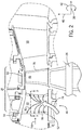
- FIG. 2 is a partial cross-sectional side view of an embodiment of the gas turbine system 10.
- the gas turbine system 10 may be described with reference to a longitudinal axis or direction 38, a radial axis or direction 40, and a circumferential axis or direction 42.
- the hot combustion gases 24 may flow from the combustors 14 ( FIG. 1 ) into the turbine 16 in a direction generally along the longitudinal axis 38, illustrated by an arrow 44.
- Each of the stages 18 of the turbine 16 includes a set of blades 46 coupled to a rotor wheel that may be rotatably attached to the shaft 26.
- the turbine 16 includes turbine nozzle assemblies 48 within each of the stages 18, and the turbine nozzle assemblies 48 direct the hot combustion gases 24 towards the set of blades 46 of the respective stage 18.
- the turbine nozzle assemblies 48 described herein may be employed in a first stage, second stage, third stage, or combinations thereof.
- Each nozzle assembly 48 may include circumferentially spaced vanes 50 that extend in the radial direction 40 between inner and outer band segments 52 and 54. Adjacent outer band segments 54 may be coupled together to form an outer annular ring extending around an inner annular ring of adjacent inner band segments 52.
- the vanes 50 may extend between the two annular rings formed by the inner and outer band segments 52 and 54.
- the gas turbine system 10 may also include shroud segments 56, which may be disposed downstream of the outer band segments 54 to direct hot combustion gases 24 flowing past the vanes 50 to the blades 46.
- shroud segments 56 may be disposed downstream of the outer band segments 54 to direct hot combustion gases 24 flowing past the vanes 50 to the blades 46.
- downstream generally refers to the direction of the combustion gases 24 through the turbine 16 along the longitudinal axis 38, as shown by the arrow 44.
- upstream generally refers to the opposite direction (e.g., towards the compressor 12) along the longitudinal axis 38.
- heated structures or components disposed along the flow path of a hot gas may be referred to as heated structures or components.
- the heated structure may be the blades 46 and other parts (e.g., vanes 50) of the turbine nozzle assembly 48.
- one or more impingements sleeves 92 may be disposed within the heated structures as shown by the dashed line 78.
- cooling air as indicated by an arrow 79 may be routed from the compressor 12 or elsewhere through impingements sleeves 92, which impinge the flow of cooling air as indicated by arrows 81 on the inner surfaces of the heated structures.
- FIG. 3 shows a sectional view of an example of a heated structure (e.g., vane 50), taken along line 3-3 of FIG. 2 .
- the heated structure may have an overall aerodynamic shape (e.g., airfoil), extending from a pressure side 80 to a suction side 82.
- the heated structure e.g., vane 50
- the heated structure may also extend from a leading edge 84 to a trailing edge 86.
- the heated structure may have a shell 88, which defines one or more internal cooling cavities 90.
- the heated structure may be cooled by passing cooling air through passages internal to the heated structure (e.g., convection cooling). For example, a portion of air 34 ( FIG.
- the compressor 12 may be diverted from the compressor 12 to flow through the one or more internal cooling cavities 90 of the heated structure (e.g., vane 50) as indicated by the arrow 79.
- one or more impingement sleeves 92 may be disposed within the one or more internal cooling cavities 90 to cool the heated structure via impingement cooling on the shell 88 as indicated by the arrows 81.
- the impingement sleeve 92 may have a shell 94, and the shell 94 may have an inner surface 96, and an outer surface 98.
- the outer surface 98 of the impingement sleeve 92 may enclose a cooling channel configured to receive cooling air.
- the impingement sleeve 92 may have a plurality of ports 100 extending from the outer surface 98 away from the inner surface 96.
- the plurality of ports 100 may each have a length 102 and an outlet 104, and there may be a distance 106 from the outlet 104 to a wall 108 of the shell 88 that forms the internal cooling cavity 90.
- the outer surface 98 of the impingement sleeve 92 may be generally parallel to the wall 108 of the corresponding internal cooling cavity 90.
- the outer surface 98 of the impingement sleeve 92 may enclose a cooling channel configured to receive cooling air (the arrows 79 and 81 of FIG. 2 ).
- the cooling air may flow through the inner surface 96 of the impingement sleeve 92, and may exit through the plurality of ports 100 from the respective outlet 104 (as shown by the arrows 81), hitting/impinging the wall 108 of the internal cooling cavity 90 with high velocity air (e.g., impingement cooling).
- high velocity air e.g., impingement cooling
- the cooling air exiting the outlet 104 of each of the plurality of ports 100 may be directed at a substantially perpendicular angle toward the wall 108.
- the length 102 of each port 100 may vary among the plurality of ports 100 so as to control the respective distance 106 between the respective outlet 104 and the wall 108 of the internal cooling cavity 90 (e.g., to allow for control of the distance of impingement to the wall 108).
- the length 102 may be the same for each of the plurality of ports 100, or the length 102 may vary for different ports of the plurality of ports 100.
- the length 102 of the ports 100 may vary to enable the distances 106 between each respective port 104 and the wall 108 to be approximately equal. Varying lengths 102 of the ports 100 may allow the cooling air to be carried to tight-to-reach areas, such as near the trailing edge 86 of the heated structure. As may be appreciated, directing cooling air toward the wall 108 of the trailing edge 86 may be difficult without the ports 100 described herein.
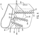
- FIG. 4 is a perspective view of an embodiment of the impingement sleeve 92 with the plurality of ports 100.
- Each of the plurality of ports 100 may have a port axis or direction 132, which is aligned with the longitudinal direction of the port 100, and the port axis 132 may be at an angle 134 relative to a surface tangent 136 of the outer surface 98 of the impingement sleeve 92.
- the angle 134 may be a constant value for all of the plurality of ports 100, or the angle 134 may vary between different ports of the plurality of ports 100.
- the angle 134 may be 90 degrees (e.g., the port 100 is perpendicularly aligned relative to the outer surface 98 of the impingement sleeve 92). In another example, the angle 134 may be any values between 0 and 180 degrees. Further, there may be one or more pins 138 between each pair 101 of the plurality of ports 100. In some embodiments, there may be one or more pins 139 between the outer surface 98 of the impingement sleeve 92 and the plurality of ports 100. For example, one end of the pin 138 may be connected to the port 100, and the other end may be connected to the outer surface 98 of the impingement sleeve 92.
- the one or more pins 138 may provide structural support for the plurality of ports 100 during the construction/building of the plurality of ports 100 so as to enable the plurality of ports 100 to be oriented at any angles 134 relative to the outer surface 98 of the impingement sleeve 92.
- Each of the one or more pins 138 may have a pin axis or direction 140, which is aligned with the longitudinal direction of the pin 138.
- the pin axis 140 of each of the one or more pins 138 may be substantially parallel to the outer surface 98 of the impingement sleeve 92 at a location proximate to the respective pin of the plurality of pins 138, such that each pin 138 substantially follows the contour of the outer surface 98 of the impingement sleeve 92.
- the pin axis 140 of each of the one or more pins 138 may be at an angle (e.g., approximately 45 degrees or smaller than 45 degrees) relative to the outer surface 98 of the impingement sleeve 92.
- FIG. 5 is a detailed perspective view of portion of the plurality of ports 100 with the one or more pins 138 between each pair 101 of the plurality of ports 100 shown in FIG. 4 .
- the impingement sleeve 92 including the plurality of ports 100 and the one or more pins 138 is built using an additive manufacturing technique such as a direct metal laser sintering (DMLS) process, wherein the impingement sleeve 92 may include any suitable laser sintered metal material (e.g., stainless steel, nickel-chromium alloy, cobalt-chromium alloy, maraging steel, aluminum alloy, titanium alloy, etc.).
- DMLS direct metal laser sintering
- the impingement sleeve 92 including the plurality of ports 100 and the one or more pins 138 may also be built using any other additive manufacturing techniques, such as 3D-printing, wherein the impingement sleeve 92 may include any suitable metal materials for the said additive manufacturing technique.
- the impingement sleeve 92 built using a DMLS process or other additive manufacturing technique may have a build axis or direction 160 (e.g., opposite to the direction as the build material is laid down).
- Each of the plurality of ports 100 may have the port axis 132 at an angle 162 relative to the build axis 160, wherein the angle 162 may be approximately 90 degrees, greater than 45 degrees, or any other angles between 0 and 90 degrees.
- the plurality of ports 100 may be distributed so as to form one or more columns 164 of ports.
- the space 166 may be constant for every adjacent port of the plurality of ports 100 (e.g., the plurality of ports 100 are equally spaced).
- the space 166 may vary for some or all of the plurality of ports 100 (e.g., the plurality of ports 100 are not equally spaced).
- the space 166 between the ports 100 of a column 164 may be different than the space 166 between two columns 164. Additionally, or in the alternative, the space 166 between ports 100 directed toward a trailing edge of the heated structure may be different (e.g., less than) the space 166 between ports 100 directed toward a broad face of the heated structure.
- each of the one or more columns 164 may have a column direction (as shown by arrow 168).
- the column direction 168 may be aligned with the build axis 160.
- the column direction 168 may also be at an angle 170 relative to the build direction 160, wherein the angle 170 may be between 0 and 90 degrees.
- the angle 170 for each of the columns 164 may result in columns 164 that are helically arranged about the outer surface 98, as shown with ports 165 of FIG. 5 .
- the angle 170 may be the same for each of the one or more columns 164 of the plurality of ports 100.
- the ports 167 of FIG. 5 are arranged with the build axis 160 such that the angle 170 is 0 degrees.
- the angle 170 may vary for different columns of the one or more columns 164 of the plurality of ports 100.
- Each of the one or more pins 138 may have the pin axis 140 at an angle 172 relative to the build axis 160, wherein the angle 172 may be any angles within a threshold support angle of the build axis 160.
- the one or more pins 138 may have the pin axis 140 at an angle relative to the outer surface 98 of the impingement sleeve 92, wherein the angle may be within a threshold support angle of the build axis 160.
- the one or more pins 138 may be built with the pin axis 140 at an approximately 45 degrees or smaller than 45 degrees relative to the outer surface 98 of the impingement sleeve 92. That is, the one or more pins 138 may be built off the outer surface 98 of the impingement sleeve 92 rather than being built axially from the ground up or off the previous port 100.
- ground as discussed herein, may refer to a base surface upon which an initial layer of an additively manufactured component is added.
- a threshold support angle is a critical angle relative to the build axis 160, such that structures/features or DMLA layers laid down at any angles smaller than the critical angle can withstand (e.g., without settling or sagging) on their own without any additional supports.
- the said threshold support angle of the build axis may be approximately 45 degrees.
- the one or more pins may have any cross sectional shapes (e.g., circular, elliptical, rectangular, hexagonal).
- Each of the one or more pins 138 may also have a characteristic width 174.
- the characteristic width 174 may be approximately 1.0, 0.5, 0.25, 0.2 millimeters, or less.
- each of the one or more pins 138 may has a cross-sectional area (e.g., perpendicular to the pin axis 140), which has a shape of a circle, a square or rectangular, or any other shapes.
- the space 176 may be a constant value for each pair of the one or more pins 138 (e.g., the one or more pins 138 are equally spaced).
- the space 176 between adjacent pins 138 may be a constant value (e.g., approximately 0.2 to 3.0 mm, or 0.2 to 1.0 mm), and the pins 138 adjacent to the outer surface 98 may be offset by the space 176.
- the pin axis 140 is substantially parallel (e.g., within 10 degrees of parallel) to the outer surface 98 of the impingement sleeve 92 and offset by the space 176.
- the space 176 may be based at least in part on the build material, the angle 172, or any combination thereof.
- the space 176 may be configured to reduce or eliminate any settling or sagging of the port 100 during the formation of the impingement sleeve 92, thereby enabling the port 100 to have a desired shape and length 102.
- the space 176 may vary for different pairs of the one or more pins 138 (e.g., the one or more pins 138 are not equally spaced).
- Each of the plurality of ports 100 may also have a characteristic width 178.
- the characteristic width 178 may be the same or different for each of the plurality of ports 100.
- the characteristic width 178 for each of the plurality of ports 100 is chosen to have certain cross-sectional area of the respective port 100 so as to achieve the designed heat transfer characteristics, cooling performance, cooling air flow volumes, cool air flow rates, cooling air flow patterns, or combinations thereof.
- the space 176 between each adjacent one or more pins 138 may be approximately 0.5 times the characteristic width 178 of the respective pair of ports 100.
- the length 102 of any of the plurality of ports 100 may be longer than 0.5 times its respective characteristic width 178. In another example, the length 102 of any of the plurality of ports 100 may be longer than its respective characteristic width 178.
- FIGS. 6-8 are cross-sectional views of different embodiments of the plurality of ports 100 perpendicular to the port axis 132.
- each of the plurality of ports 100 may have a hollow cross section that generally has a shape of a circle 190, a square or rectangular 192, a teardrop 194, or any other shapes.
- the characteristic width 178 is the diameter of the circular shape 190, the diagonal or edge length of the rectangular shape 192, or the major axis of the teardrop shape 194.
- Each of the plurality of ports 100 may have a thickness 196 of any suitable values, smaller than the characteristic width 178.
- the thickness 196 and the characteristic width 174 may have the same value, and which could be the smallest resolution of a DMLS machine or a 3D printer.
- each of the plurality of ports 100 may have one or more tapered edges 198.
- the impingement sleeve 92 and the ports 100 may have different cross sections than those illustrated in FIGS. 3-8 .
- the impingement sleeves and impingement tubes e.g., ports
- the impingement sleeves and impingement tubes may have the shapes or cross sections of those illustrated and described in U.S. Patent Application No. 14/725,374 , entitled "Article, Component, and Method of Forming an Article," filed on May 29, 2015, which is hereby incorporated by reference into the present disclosure.
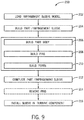
- FIG. 9 is a flow chart illustrating a method 200 for building and implementing the impingement sleeve 92.
- the method 200 includes loading (block 202) the computer model (e.g., a three-dimensional (3D) computer-assisted-design (CAD) model) of the impingement sleeve 92 to the manufacturing system (e.g., a DMLS machine or a 3D printer).
- the method 200 also includes building (block 204) the physical part (e.g., the impingement sleeve 92) based on the loaded 3D CAD file, wherein the DMLS machine builds the impingement sleeve 92 in a layer-by-layer manner in the build direction.
- the computer model e.g., a three-dimensional (3D) computer-assisted-design (CAD) model
- the manufacturing system e.g., a DMLS machine or a 3D printer.
- the method 200 also includes building (block 204) the physical part (e.g.
- such a process may include building (block 206) part or parts of the main body (e.g., shell 94) of the impingement sleeve 92, then building (block 208) the one or more pins 138, followed by building (block 210) the plurality of ports 100. Steps described in blocks 206 to 210 are repeated for each layer until the entire impingement sleeve 92 is built. As may be appreciated, steps 206, 208, and 210 may be concurrent or sequential in any combination of orders (e.g., the part body, pins and ports may be built concurrently or in any combination of orders depending on the sleeve structure to be built within each build layer.
- the method 190 method also includes installing (block 216) the impingement sleeve 92 in the heated structure (e.g., nozzle, blade) of the turbine stage 18.
Landscapes
- Engineering & Computer Science (AREA)
- Mechanical Engineering (AREA)
- General Engineering & Computer Science (AREA)
- Chemical & Material Sciences (AREA)
- Combustion & Propulsion (AREA)
- Physics & Mathematics (AREA)
- Fluid Mechanics (AREA)
- Turbine Rotor Nozzle Sealing (AREA)
- Powder Metallurgy (AREA)
Abstract
Description
- The subject matter disclosed herein relates generally to gas turbines, and, more particularly to systems and methods for cooling of turbine nozzles.
- A gas turbine engine combusts a fuel to generate hot combustion gases, which flow through a turbine to drive a load and/or a compressor. In such system, the overall gas turbine performance and efficiency may be increased by increasing internal combustion temperatures. The components that are subject to the high temperatures in the hot gas path (e.g., hot gas path components) may be cooled by routing cooling air from the compressor or elsewhere through impingement sleeves that impinge the flow of the cooling air on the inner surfaces of the hot gas path components. Although the use of this method may provide cooling for the hot gas path components, a further increase in cooling efficiency is desired.
- Certain embodiments commensurate in scope with the originally claimed invention are summarized below. These embodiments are not intended to limit the scope of the claimed invention, but rather these embodiments are intended only to provide a brief summary of possible forms of the invention. Indeed, the invention may encompass a variety of forms that may be similar to or different from the embodiments set forth below.
- In one embodiment, a system including an impingement sleeve configured to receive a cooling flow. The impingement sleeve includes a column of ports extending from an outer surface of the impingement sleeve, wherein each port of the column of ports is configured to direct an impingement stream toward a heated structure, and each impingement stream includes a portion of the cooling flow. The impingement sleeve also includes one or more pins disposed outside the outer surface relative to the cooling flow, wherein each pin of the one or more pins is coupled between pairs of ports of the column of ports.
- In another embodiment, a system includes an additively manufactured impingement sleeve configured to receive a cooling flow. The impingement sleeve includes a build axis substantially perpendicular to a plurality of layers forming the additively manufactured impingement sleeve. The impingement sleeve also includes a plurality of ports extending from an outer surface of the impingement sleeve, wherein the plurality of ports includes a plurality of port columns. Each port of the plurality of ports is configured to direct an impingement stream toward a heated structure, and each impingement stream includes a portion of the cooling flow. The impingement sleeve further includes a plurality of pins disposed outside the outer surface relative to the cooling flow. Each port column includes one or more pins of the plurality of pins coupled between pairs of ports of the plurality of ports along the respective port column to support the respective port column during additive manufacturing. Each pin of the plurality of pins is disposed along a respective pin axis within a threshold angle of the build axis.
- In another embodiment, a method includes additively manufacturing the impingement sleeve in a build direction, wherein the impingement sleeve includes an outer surface, and a plurality of ports extending from the outer surface at angles greater than 45 degrees relative to the build direction. Each port of the plurality of ports is configured to direct an impingement stream toward a heated structure. The impingement sleeve also includes a plurality of pins, wherein each pin of the plurality of pins is disposed along a respective pin axis within a threshold angle of the build direction. Each pin of the plurality of pins is coupled to at least one port of the plurality of ports, and each pin of the plurality of pins is configured to support the at least one port during additive manufacturing. The method also includes inserting the additively manufactured impingement sleeve in a nozzle of a gas turbine.
- These and other features, aspects, and advantages of the present invention will become better understood when the following detailed description is read with reference to the accompanying drawings in which like characters represent like parts throughout the drawings, wherein:
-
FIG. 1 is a block diagram of an embodiment of a gas turbine system; -
FIG. 2 is a partial side cross-sectional view of the gas turbine system; -
FIG. 3 is a cross-sectional view of an embodiment of airfoil heated structure of the gas turbine system with an impingement sleeve; -
FIG. 4 is a perspective view of an embodiment of the impingement sleeve with a plurality of ports; -
FIG. 5 is a partial perspective view of an embodiment of a portion of the impingement sleeve ofFIG. 4 with the plurality of ports; -
FIG. 6 is a cross-sectional view of an embodiment of one of the plurality ports ofFIG. 5 ; -
FIG. 7 is a cross-sectional view of another embodiment of one of the plurality ports ofFIG. 5 ; -
FIG. 8 is a cross-sectional view of another embodiment of one of the plurality ports ofFIG. 5 ; and -
FIG. 9 is a flow chart of a method for building and implementing the impingement sleeve. - One or more specific embodiments of the present invention will be described below. In an effort to provide a concise description of these embodiments, all features of an actual implementation may not be described in the specification. It should be appreciated that in the development of any such actual implementation, as in any engineering or design project, numerous implementation-specific decisions must be made to achieve the developers' specific goals, such as compliance with system-related and business-related constraints, which may vary from one implementation to another. Moreover, it should be appreciated that such a development effort might be complex and time consuming, but would nevertheless be a routine undertaking of design, fabrication, and manufacture for those of ordinary skill having the benefit of this disclosure.
- When introducing elements of various embodiments of the present invention, the articles "a," "an," "the," and "said" are intended to mean that there are one or more of the elements. The terms "comprising," "including," and "having" are intended to be inclusive and mean that there may be additional elements other than the listed elements.
- Gas turbine systems in accordance with the present disclosure may provide cooling within a turbine section of a gas turbine system with types of hardware, such as impingement sleeves. Certain gas turbine systems may include impingement sleeves positioned within heated parts (e.g., airfoils) or impingement sleeves positioned adjacent to casings of the heated parts of the gas turbine. Impingement cooling operates by impinging (e.g., hitting) the inner surface of the heated component with high velocity cooling air. Impingement cooling allows more heat to be transferred by convection (e.g., than regular convection cooling does), and impingement cooling is often used in regions of great heat load, such as the turbine blades and turbine nozzles. For example, the turbine blades or airfoils of other heated components of the turbine may be hollow with one or more cavities, and the impingement sleeves may be inserted within those cavities.
- Some embodiments of impingement sleeves for impingement cooling may include holes or air outlets for the cooling air to exit and impinge the inner surface of the heated structures. However, depending on the conformation between the impingement sleeve and the inner surface of the heated structures, it may be difficult to control the impingement distance (e.g., distance from the air outlet to the inner surface). Furthermore, it may be difficult to direct the cooling air to tight-to-reach spots of the heated structure. For example, the heated structure may have narrow corners or sharp transitions at the respective surface contour such that it is difficult for the impingement sleeve to conform with such shape so as to effectively direct the air to cool the inner surface. Accordingly, there is a desire for impingement sleeves that provide effective cooling of the heated structures of the gas turbine system. For example, the systems described herein may enable control of the impingement distance and control of directing cooling air to desirable spots of the heated structure, and thus may improve the cooling efficiency of the impingement sleeves.
- Turning to the drawings,
FIG. 1 illustrates a block diagram of an embodiment of agas turbine system 10, which may include features (e.g., cooling features such as impingement sleeves) to improve cooling within certain portions of thesystem 10. As appreciated, the systems and methods described herein may be used in any turbine system, such as gas turbine systems and steam turbine systems, and is not intended to be limited to any particular machine or system. As shown, thesystem 10 includes acompressor 12, aturbine combustor 14, and aturbine 16, wherein theturbine 16 may include one or moreseparate stages 18. Thesystem 10 may include one ormore combustors 14 that include one ormore fuel nozzles 20 configured to receive a liquid fuel and/orgas fuel 22, such as natural gas or syngas. - The
turbine combustors 14 ignite and combust a fuel-air mixture, and then pass hot pressurized combustion gases 24 (e.g., exhaust) into theturbine 16. Turbine blades are coupled to ashaft 26, which is also coupled to several other components throughout thegas turbine system 10. As thecombustion gases 24 pass through the turbine blades in theturbine 16, theturbine 16 is driven into rotation, which causes theshaft 26 to rotate. Eventually, thecombustion gases 24 exit thegas turbine system 10 via anexhaust outlet 28. Further, theshaft 26 may be coupled to aload 30, which is powered via rotation of theshaft 26. For example, theload 30 may be any suitable devices that may generate power via the rotational output of thegas turbine system 10, such as an electrical generator, a propeller of an airplane, and so forth. - Compressor blades may be included as components of the
compressor 12. The blades within thecompressor 12 are coupled to theshaft 26, and will rotate as theshaft 26 is driven to rotate by theturbine 16, as described above. Anintake 32feeds air 34 into thecompressor 12, and the rotation of the blades within thecompressor 12 compresses theair 34 to generatepressurized air 36. Thepressurized air 36 is then fed into thefuel nozzles 20 of theturbine combustors 14. The fuel nozzles 20 mix thepressurized air 36 andfuel 22 to produce a suitable mixture ratio for combustion (e.g., a combustion that causes the fuel to more completely burn). -
FIG. 2 is a partial cross-sectional side view of an embodiment of thegas turbine system 10. As shown, thegas turbine system 10 may be described with reference to a longitudinal axis ordirection 38, a radial axis ordirection 40, and a circumferential axis ordirection 42. Thehot combustion gases 24 may flow from the combustors 14 (FIG. 1 ) into theturbine 16 in a direction generally along thelongitudinal axis 38, illustrated by anarrow 44. Each of thestages 18 of theturbine 16 includes a set ofblades 46 coupled to a rotor wheel that may be rotatably attached to theshaft 26. Theturbine 16 includesturbine nozzle assemblies 48 within each of thestages 18, and theturbine nozzle assemblies 48 direct thehot combustion gases 24 towards the set ofblades 46 of therespective stage 18. Theturbine nozzle assemblies 48 described herein may be employed in a first stage, second stage, third stage, or combinations thereof. Eachnozzle assembly 48 may include circumferentially spacedvanes 50 that extend in theradial direction 40 between inner andouter band segments outer band segments 54 may be coupled together to form an outer annular ring extending around an inner annular ring of adjacentinner band segments 52. Thevanes 50 may extend between the two annular rings formed by the inner andouter band segments gas turbine system 10 may also includeshroud segments 56, which may be disposed downstream of theouter band segments 54 to directhot combustion gases 24 flowing past thevanes 50 to theblades 46. As may be appreciated, the term "downstream" generally refers to the direction of thecombustion gases 24 through theturbine 16 along thelongitudinal axis 38, as shown by thearrow 44. Likewise, the term "upstream" generally refers to the opposite direction (e.g., towards the compressor 12) along thelongitudinal axis 38. - Structures or components disposed along the flow path of a hot gas (e.g., the combustion gases 24) may be referred to as heated structures or components. In one example, the heated structure may be the
blades 46 and other parts (e.g., vanes 50) of theturbine nozzle assembly 48. In some embodiments, to cool the heated structures (e.g., vanes 50), one ormore impingements sleeves 92 may be disposed within the heated structures as shown by the dashedline 78. For example, cooling air as indicated by anarrow 79 may be routed from thecompressor 12 or elsewhere throughimpingements sleeves 92, which impinge the flow of cooling air as indicated byarrows 81 on the inner surfaces of the heated structures. -
FIG. 3 shows a sectional view of an example of a heated structure (e.g., vane 50), taken along line 3-3 ofFIG. 2 . The heated structure may have an overall aerodynamic shape (e.g., airfoil), extending from apressure side 80 to asuction side 82. The heated structure (e.g., vane 50) may also extend from a leadingedge 84 to a trailingedge 86. The heated structure may have ashell 88, which defines one or moreinternal cooling cavities 90. The heated structure may be cooled by passing cooling air through passages internal to the heated structure (e.g., convection cooling). For example, a portion of air 34 (FIG. 1 ) may be diverted from thecompressor 12 to flow through the one or moreinternal cooling cavities 90 of the heated structure (e.g., vane 50) as indicated by thearrow 79. Further, one or moreimpingement sleeves 92 may be disposed within the one or moreinternal cooling cavities 90 to cool the heated structure via impingement cooling on theshell 88 as indicated by thearrows 81. - The
impingement sleeve 92 may have ashell 94, and theshell 94 may have aninner surface 96, and anouter surface 98. Theouter surface 98 of theimpingement sleeve 92 may enclose a cooling channel configured to receive cooling air. Further, theimpingement sleeve 92 may have a plurality ofports 100 extending from theouter surface 98 away from theinner surface 96. The plurality ofports 100 may each have alength 102 and anoutlet 104, and there may be adistance 106 from theoutlet 104 to awall 108 of theshell 88 that forms theinternal cooling cavity 90. In some embodiments, theouter surface 98 of theimpingement sleeve 92 may be generally parallel to thewall 108 of the corresponding internal coolingcavity 90. - As set forth above, the
outer surface 98 of theimpingement sleeve 92 may enclose a cooling channel configured to receive cooling air (thearrows FIG. 2 ). The cooling air may flow through theinner surface 96 of theimpingement sleeve 92, and may exit through the plurality ofports 100 from the respective outlet 104 (as shown by the arrows 81), hitting/impinging thewall 108 of theinternal cooling cavity 90 with high velocity air (e.g., impingement cooling). This allows more heat to be transferred by convection from the shell to the cooling air, and thereby enhances the cooling of the heated structure (e.g., vane 50). In one example, the cooling air exiting theoutlet 104 of each of the plurality of ports 100 (e.g., each impingement stream) may be directed at a substantially perpendicular angle toward thewall 108. Thelength 102 of eachport 100 may vary among the plurality ofports 100 so as to control therespective distance 106 between therespective outlet 104 and thewall 108 of the internal cooling cavity 90 (e.g., to allow for control of the distance of impingement to the wall 108). For example, thelength 102 may be the same for each of the plurality ofports 100, or thelength 102 may vary for different ports of the plurality ofports 100. In some embodiments, thelength 102 of theports 100 may vary to enable thedistances 106 between eachrespective port 104 and thewall 108 to be approximately equal. Varyinglengths 102 of theports 100 may allow the cooling air to be carried to tight-to-reach areas, such as near the trailingedge 86 of the heated structure. As may be appreciated, directing cooling air toward thewall 108 of the trailingedge 86 may be difficult without theports 100 described herein. -
FIG. 4 is a perspective view of an embodiment of theimpingement sleeve 92 with the plurality ofports 100. Each of the plurality ofports 100 may have a port axis ordirection 132, which is aligned with the longitudinal direction of theport 100, and theport axis 132 may be at anangle 134 relative to asurface tangent 136 of theouter surface 98 of theimpingement sleeve 92. Theangle 134 may be a constant value for all of the plurality ofports 100, or theangle 134 may vary between different ports of the plurality ofports 100. In one example, theangle 134 may be 90 degrees (e.g., theport 100 is perpendicularly aligned relative to theouter surface 98 of the impingement sleeve 92). In another example, theangle 134 may be any values between 0 and 180 degrees. Further, there may be one ormore pins 138 between eachpair 101 of the plurality ofports 100. In some embodiments, there may be one ormore pins 139 between theouter surface 98 of theimpingement sleeve 92 and the plurality ofports 100. For example, one end of thepin 138 may be connected to theport 100, and the other end may be connected to theouter surface 98 of theimpingement sleeve 92. In addition, there may also be one ormore pins 141 between the plurality ofports 100 and a ground. One may appreciate that the term "ground," as discussed herein, may refer to a base surface upon which an initial layer of an additively manufactured component is added. The one ormore pins 138 may provide structural support for the plurality ofports 100 during the construction/building of the plurality ofports 100 so as to enable the plurality ofports 100 to be oriented at anyangles 134 relative to theouter surface 98 of theimpingement sleeve 92. Each of the one ormore pins 138 may have a pin axis ordirection 140, which is aligned with the longitudinal direction of thepin 138. Thepin axis 140 of each of the one ormore pins 138 may be substantially parallel to theouter surface 98 of theimpingement sleeve 92 at a location proximate to the respective pin of the plurality ofpins 138, such that eachpin 138 substantially follows the contour of theouter surface 98 of theimpingement sleeve 92. In some embodiments, thepin axis 140 of each of the one ormore pins 138 may be at an angle (e.g., approximately 45 degrees or smaller than 45 degrees) relative to theouter surface 98 of theimpingement sleeve 92. -
FIG. 5 is a detailed perspective view of portion of the plurality ofports 100 with the one ormore pins 138 between eachpair 101 of the plurality ofports 100 shown inFIG. 4 . In some embodiments, theimpingement sleeve 92 including the plurality ofports 100 and the one ormore pins 138 is built using an additive manufacturing technique such as a direct metal laser sintering (DMLS) process, wherein theimpingement sleeve 92 may include any suitable laser sintered metal material (e.g., stainless steel, nickel-chromium alloy, cobalt-chromium alloy, maraging steel, aluminum alloy, titanium alloy, etc.). Theimpingement sleeve 92 including the plurality ofports 100 and the one ormore pins 138 may also be built using any other additive manufacturing techniques, such as 3D-printing, wherein theimpingement sleeve 92 may include any suitable metal materials for the said additive manufacturing technique. Theimpingement sleeve 92 built using a DMLS process or other additive manufacturing technique may have a build axis or direction 160 (e.g., opposite to the direction as the build material is laid down). - Each of the plurality of
ports 100 may have theport axis 132 at anangle 162 relative to thebuild axis 160, wherein theangle 162 may be approximately 90 degrees, greater than 45 degrees, or any other angles between 0 and 90 degrees. The plurality ofports 100 may be distributed so as to form one ormore columns 164 of ports. There may be aspace 166 between adjacent ports of the plurality ofports 100. In one example, thespace 166 may be constant for every adjacent port of the plurality of ports 100 (e.g., the plurality ofports 100 are equally spaced). In another example, thespace 166 may vary for some or all of the plurality of ports 100 (e.g., the plurality ofports 100 are not equally spaced). For example, thespace 166 between theports 100 of acolumn 164 may be different than thespace 166 between twocolumns 164. Additionally, or in the alternative, thespace 166 betweenports 100 directed toward a trailing edge of the heated structure may be different (e.g., less than) thespace 166 betweenports 100 directed toward a broad face of the heated structure. - Further, each of the one or
more columns 164 may have a column direction (as shown by arrow 168). Thecolumn direction 168 may be aligned with thebuild axis 160. Thecolumn direction 168 may also be at anangle 170 relative to thebuild direction 160, wherein theangle 170 may be between 0 and 90 degrees. In some embodiments, theangle 170 for each of thecolumns 164 may result incolumns 164 that are helically arranged about theouter surface 98, as shown withports 165 ofFIG. 5 . In one example, theangle 170 may be the same for each of the one ormore columns 164 of the plurality ofports 100. For example, theports 167 ofFIG. 5 are arranged with thebuild axis 160 such that theangle 170 is 0 degrees. In another example, theangle 170 may vary for different columns of the one ormore columns 164 of the plurality ofports 100. Each of the one ormore pins 138 may have thepin axis 140 at anangle 172 relative to thebuild axis 160, wherein theangle 172 may be any angles within a threshold support angle of thebuild axis 160. In some embodiments, the one ormore pins 138 may have thepin axis 140 at an angle relative to theouter surface 98 of theimpingement sleeve 92, wherein the angle may be within a threshold support angle of thebuild axis 160. For example, the one ormore pins 138 may be built with thepin axis 140 at an approximately 45 degrees or smaller than 45 degrees relative to theouter surface 98 of theimpingement sleeve 92. That is, the one ormore pins 138 may be built off theouter surface 98 of theimpingement sleeve 92 rather than being built axially from the ground up or off theprevious port 100. One may appreciate that the term "ground," as discussed herein, may refer to a base surface upon which an initial layer of an additively manufactured component is added. As may be appreciated, a threshold support angle is a critical angle relative to thebuild axis 160, such that structures/features or DMLA layers laid down at any angles smaller than the critical angle can withstand (e.g., without settling or sagging) on their own without any additional supports. The said threshold support angle of the build axis may be approximately 45 degrees. The one or more pins may have any cross sectional shapes (e.g., circular, elliptical, rectangular, hexagonal). Each of the one ormore pins 138 may also have acharacteristic width 174. Thecharacteristic width 174 may be approximately 1.0, 0.5, 0.25, 0.2 millimeters, or less. As may be appreciated, each of the one ormore pins 138 may has a cross-sectional area (e.g., perpendicular to the pin axis 140), which has a shape of a circle, a square or rectangular, or any other shapes. - There may be a
space 176 between each adjacent pin of the one ormore pins 138 coupled between eachpair 101 of the plurality ofports 100. In one example, thespace 176 may be a constant value for each pair of the one or more pins 138 (e.g., the one ormore pins 138 are equally spaced). For example, thespace 176 betweenadjacent pins 138 may be a constant value (e.g., approximately 0.2 to 3.0 mm, or 0.2 to 1.0 mm), and thepins 138 adjacent to theouter surface 98 may be offset by thespace 176. In some embodiments, thepin axis 140 is substantially parallel (e.g., within 10 degrees of parallel) to theouter surface 98 of theimpingement sleeve 92 and offset by thespace 176. Thespace 176 may be based at least in part on the build material, theangle 172, or any combination thereof. Thespace 176 may be configured to reduce or eliminate any settling or sagging of theport 100 during the formation of theimpingement sleeve 92, thereby enabling theport 100 to have a desired shape andlength 102. In some embodiments, thespace 176 may vary for different pairs of the one or more pins 138 (e.g., the one ormore pins 138 are not equally spaced). - Each of the plurality of
ports 100 may also have acharacteristic width 178. Thecharacteristic width 178 may be the same or different for each of the plurality ofports 100. For example, thecharacteristic width 178 for each of the plurality ofports 100 is chosen to have certain cross-sectional area of therespective port 100 so as to achieve the designed heat transfer characteristics, cooling performance, cooling air flow volumes, cool air flow rates, cooling air flow patterns, or combinations thereof. - Accordingly, the
space 176 between each adjacent one ormore pins 138 may be approximately 0.5 times thecharacteristic width 178 of the respective pair ofports 100. Thelength 102 of any of the plurality ofports 100 may be longer than 0.5 times its respectivecharacteristic width 178. In another example, thelength 102 of any of the plurality ofports 100 may be longer than its respectivecharacteristic width 178. -
FIGS. 6-8 are cross-sectional views of different embodiments of the plurality ofports 100 perpendicular to theport axis 132. As shown, each of the plurality ofports 100 may have a hollow cross section that generally has a shape of acircle 190, a square or rectangular 192, ateardrop 194, or any other shapes. As may be appreciated, thecharacteristic width 178 is the diameter of thecircular shape 190, the diagonal or edge length of therectangular shape 192, or the major axis of theteardrop shape 194. Each of the plurality ofports 100 may have athickness 196 of any suitable values, smaller than thecharacteristic width 178. In some embodiments, thethickness 196 and thecharacteristic width 174 may have the same value, and which could be the smallest resolution of a DMLS machine or a 3D printer. In some embodiment, each of the plurality ofports 100 may have one or moretapered edges 198. It may be appreciated that some embodiments of theimpingement sleeve 92 and theports 100 may have different cross sections than those illustrated inFIGS. 3-8 . For example, the impingement sleeves and impingement tubes (e.g., ports) may have the shapes or cross sections of those illustrated and described inU.S. Patent Application No. 14/725,374 -
FIG. 9 is a flow chart illustrating amethod 200 for building and implementing theimpingement sleeve 92. One or more of the steps of themethod 200 may be executed. Themethod 200 includes loading (block 202) the computer model (e.g., a three-dimensional (3D) computer-assisted-design (CAD) model) of theimpingement sleeve 92 to the manufacturing system (e.g., a DMLS machine or a 3D printer). Themethod 200 also includes building (block 204) the physical part (e.g., the impingement sleeve 92) based on the loaded 3D CAD file, wherein the DMLS machine builds theimpingement sleeve 92 in a layer-by-layer manner in the build direction. For example, such a process may include building (block 206) part or parts of the main body (e.g., shell 94) of theimpingement sleeve 92, then building (block 208) the one ormore pins 138, followed by building (block 210) the plurality ofports 100. Steps described inblocks 206 to 210 are repeated for each layer until theentire impingement sleeve 92 is built. As may be appreciated, steps 206, 208, and 210 may be concurrent or sequential in any combination of orders (e.g., the part body, pins and ports may be built concurrently or in any combination of orders depending on the sleeve structure to be built within each build layer. That is, some layers may add to only the part body, and some layers may add to the part body, the pins, and the ports. As the last layer is built and theimpingement sleeve 92 is cooled and solidified, the building of theimpingement sleeve 92 is completed (block 212). Optionally, the one ormore pins 138 may be removed (block 214) such that the plurality ofports 100 are supported by theshell 94 without thepins 138. Themethod 190 method also includes installing (block 216) theimpingement sleeve 92 in the heated structure (e.g., nozzle, blade) of theturbine stage 18. - This written description uses examples to disclose the invention and also to enable any person skilled in the art to practice the invention, including making and using any devices or systems and performing any incorporated methods. The patentable scope of the invention is defined by the claims, and may include other examples that occur to those skilled in the art. Such other examples are intended to be within the scope of the claims if they have structural elements that do not differ from the literal language of the claims, or if they include equivalent structural elements with insubstantial differences from the literal languages of the claims.
- Various aspects and embodiments of the present invention are defined by the following numbered clauses:
- 1. A system comprising:
- an impingement sleeve configured to receive a cooling flow, wherein the impingement sleeve comprises:
- a column of ports extending from an outer surface of the impingement sleeve, wherein each port of the column of ports is configured to direct an impingement stream toward a heated structure, and each impingement stream comprises a portion of the cooling flow; and
- one or more pins disposed outside the outer surface relative to the cooling flow, wherein each pin of the one or more pins is coupled to at least one port of the column of ports.
- an impingement sleeve configured to receive a cooling flow, wherein the impingement sleeve comprises:
- 2. The system of
clause 1, wherein the impingement sleeve comprises an additive manufactured impingement sleeve having a build axis, wherein each pin of the one or more pins is aligned along a respective pin axis that is within a threshold support angle of the build axis. - 3. The system of any preceding clause, wherein one or more ports of the column of ports extends from the outer surface at approximately 90 degrees relative to the build axis.
- 4. The system of any preceding clause, wherein the additive manufactured impingement sleeve comprises a laser sintered metal material.
- 5. The system of any preceding clause, wherein the one or more pins comprises an array of pins coupled between pairs of ports of the column of ports.
- 6. The system of any preceding clause, wherein an inner layer of pins of the array pins coupled between a respective pair of ports of the column of ports is spaced within approximately 0.5 times a diameter of the ports of the respective pair of ports, wherein the inner layer of pins is nearer to the outer surface than other pins of the array of pins.
- 7. The system of any preceding clause, wherein a first port of the column of ports extends from the outer surface more than a diameter of the first port.
- 8. The system of any preceding clause, wherein the outer surface of the impingement sleeve encloses a cooling channel configured to receive the cooling flow.
- 9. The system of any preceding clause, comprising the heated structure, wherein the heated structure comprises a nozzle of a gas turbine, wherein the impingement sleeve is disposed within a cavity of the nozzle, and each impingement stream is directed toward an interior surface of the nozzle.
- 10. The system of any preceding clause, wherein each impingement stream is directed at a substantially perpendicular angle toward the interior surface of the nozzle.
- 11. The system of any preceding clause, wherein each pin of the one or more pins comprises a characteristic width less than approximately 0.25 mm.
- 12. A system comprising:
- an additively manufactured impingement sleeve configured to receive a cooling flow, wherein the impingement sleeve comprises:
- a build axis substantially perpendicular to a plurality of layers forming the additively manufactured impingement sleeve;
- a plurality of ports extending from an outer surface of the impingement sleeve, wherein the plurality of ports comprises a plurality of port columns, each port of the plurality of ports is configured to direct an impingement stream toward a heated structure, and each impingement stream comprises a portion of the cooling flow; and
- a plurality of pins disposed outside the outer surface relative to the cooling flow, wherein each port column comprises one or more pins of the plurality of pins coupled to at least one port of the plurality of ports along the respective port column to support the respective port column during additive manufacturing, and each pin of the plurality of pins is disposed along a respective pin axis within a threshold angle of the build axis.
- an additively manufactured impingement sleeve configured to receive a cooling flow, wherein the impingement sleeve comprises:
- 13. The system of any preceding clause, wherein a subset of ports of the plurality of ports extends more than a diameter of the subset of ports, and the subset of ports of the plurality of ports extends from the outer surface at angles greater than 45 degrees relative to the build axis
- 14. The system of any preceding clause, wherein the pin axis of each pin of the plurality of pins is substantially parallel to the outer surface of the impingement sleeve proximate to the respective pin of the plurality of pins.
- 15. The system of any preceding clause, wherein the additive manufactured impingement sleeve comprises a laser sintered material, and the laser sintered material comprises a stainless steel, or a nickel-chromium alloy.
- 16. The system of any preceding clause, wherein each impingement stream is directed at a substantially perpendicular angle toward the heated structure.
- 17. A method comprising:
- additively manufacturing the impingement sleeve in a build direction, wherein the impingement sleeve comprises:
- an outer surface;
- a plurality of ports extending from the outer surface at angles greater than 45 degrees relative to the build direction, wherein each port of the plurality of ports is configured to direct an impingement stream toward a heated structure; and
- a plurality of pins, wherein each pin of the plurality of pins is disposed along a respective pin axis within a threshold angle of the build direction, each pin of the plurality of pins is coupled to at least one port of the plurality of ports, and each pin of the plurality of pins is configured to support the at least one port during additive manufacturing; and
- inserting the additively manufactured impingement sleeve in a nozzle of a gas turbine.
- additively manufacturing the impingement sleeve in a build direction, wherein the impingement sleeve comprises:
- 18. The method of any preceding clause, comprising removing one or more pins of the plurality of pins prior to inserting the additively manufactured impingement sleeve in the nozzle of the gas turbine.
- 19. The method of any preceding clause, comprising removing each pin of the plurality of pins prior to inserting the additively manufactured impingement sleeve in the nozzle of the gas turbine.
- 20. The method of any preceding clause, wherein each port of the plurality of ports extends at least 0.5 of a diameter of the respective port from the outer surface.
Claims (15)
- A system comprising:an impingement sleeve configured to receive a cooling flow, wherein the impingement sleeve comprises:a column of ports extending from an outer surface of the impingement sleeve, wherein each port of the column of ports is configured to direct an impingement stream toward a heated structure, and each impingement stream comprises a portion of the cooling flow; andone or more pins disposed outside the outer surface relative to the cooling flow, wherein each pin of the one or more pins is coupled to at least one port of the column of ports.
- The system of claim 1, wherein the impingement sleeve comprises an additive manufactured impingement sleeve having a build axis, wherein each pin of the one or more pins is aligned along a respective pin axis that is within a threshold support angle of the build axis.
- The system of claim 2, wherein one or more ports of the column of ports extends from the outer surface at approximately 90 degrees relative to the build axis.
- The system of claim 2 or 3, wherein the additive manufactured impingement sleeve comprises a laser sintered metal material.
- The system of any preceding claim, wherein the one or more pins comprises an array of pins coupled between pairs of ports of the column of ports.
- The system of claim 5, wherein an inner layer of pins of the array pins coupled between a respective pair of ports of the column of ports is spaced within approximately 0.5 times a diameter of the ports of the respective pair of ports, wherein the inner layer of pins is nearer to the outer surface than other pins of the array of pins.
- The system of any preceding claim, wherein a first port of the column of ports extends from the outer surface more than a diameter of the first port.
- The system of any preceding claim, wherein the outer surface of the impingement sleeve encloses a cooling channel configured to receive the cooling flow.
- The system of any preceding claim, comprising the heated structure, wherein the heated structure comprises a nozzle of a gas turbine, wherein the impingement sleeve is disposed within a cavity of the nozzle, and each impingement stream is directed toward an interior surface of the nozzle.
- The system of any preceding claim, wherein each impingement stream is directed at a substantially perpendicular angle toward the interior surface of the nozzle.
- The system of any preceding claim, wherein each pin of the one or more pins comprises a characteristic width less than approximately 0.25 mm.
- A method comprising:additively manufacturing the impingement sleeve in a build direction, wherein the impingement sleeve comprises:an outer surface;a plurality of ports extending from the outer surface at angles greater than 45 degrees relative to the build direction, wherein each port of the plurality of ports is configured to direct an impingement stream toward a heated structure; anda plurality of pins, wherein each pin of the plurality of pins is disposed along a respective pin axis within a threshold angle of the build direction, each pin of the plurality of pins is coupled to at least one port of the plurality of ports, and each pin of the plurality of pins is configured to support the at least one port during additive manufacturing; andinserting the additively manufactured impingement sleeve in a nozzle of a gas turbine.
- The method of claim 12, comprising removing one or more pins of the plurality of pins prior to inserting the additively manufactured impingement sleeve in the nozzle of the gas turbine.
- The method of claim 13, comprising removing each pin of the plurality of pins prior to inserting the additively manufactured impingement sleeve in the nozzle of the gas turbine.
- The method of claim 12, 13 or 14, wherein each port of the plurality of ports extends at least 0.5 of a diameter of the respective port from the outer surface.
Applications Claiming Priority (1)
| Application Number | Priority Date | Filing Date | Title |
|---|---|---|---|
| US15/016,498 US10184343B2 (en) | 2016-02-05 | 2016-02-05 | System and method for turbine nozzle cooling |
Publications (2)
| Publication Number | Publication Date |
|---|---|
| EP3203022A1 true EP3203022A1 (en) | 2017-08-09 |
| EP3203022B1 EP3203022B1 (en) | 2019-04-10 |
Family
ID=57965789
Family Applications (1)
| Application Number | Title | Priority Date | Filing Date |
|---|---|---|---|
| EP17154676.5A Active EP3203022B1 (en) | 2016-02-05 | 2017-02-03 | Cooled turbine nozzle and manufacturing method thereof |
Country Status (5)
| Country | Link |
|---|---|
| US (1) | US10184343B2 (en) |
| EP (1) | EP3203022B1 (en) |
| JP (1) | JP6937583B2 (en) |
| KR (1) | KR102712907B1 (en) |
| CN (1) | CN107044302B (en) |
Families Citing this family (6)
| Publication number | Priority date | Publication date | Assignee | Title |
|---|---|---|---|---|
| US10739087B2 (en) * | 2015-09-08 | 2020-08-11 | General Electric Company | Article, component, and method of forming an article |
| US20180149028A1 (en) | 2016-11-30 | 2018-05-31 | General Electric Company | Impingement insert for a gas turbine engine |
| US10494948B2 (en) * | 2017-05-09 | 2019-12-03 | General Electric Company | Impingement insert |
| US10584596B2 (en) * | 2017-12-22 | 2020-03-10 | United Technologies Corporation | Gas turbine engine components having internal cooling features |
| US11702941B2 (en) * | 2018-11-09 | 2023-07-18 | Raytheon Technologies Corporation | Airfoil with baffle having flange ring affixed to platform |
| US11525401B2 (en) * | 2021-01-11 | 2022-12-13 | Honeywell International Inc. | Impingement baffle for gas turbine engine |
Citations (3)
| Publication number | Priority date | Publication date | Assignee | Title |
|---|---|---|---|---|
| EP0698725A2 (en) * | 1994-08-26 | 1996-02-28 | ABB Management AG | Impingement cooling of wall portion |
| EP2716868A2 (en) * | 2012-10-03 | 2014-04-09 | Rolls-Royce plc | Hollow airfoil with multiple-part insert |
| EP2975217A1 (en) * | 2014-07-15 | 2016-01-20 | United Technologies Corporation | Using inserts to balance heat transfer and stress in high temperature alloys |
Family Cites Families (15)
| Publication number | Priority date | Publication date | Assignee | Title |
|---|---|---|---|---|
| GB2326706A (en) * | 1997-06-25 | 1998-12-30 | Europ Gas Turbines Ltd | Heat transfer structure |
| US6237344B1 (en) | 1998-07-20 | 2001-05-29 | General Electric Company | Dimpled impingement baffle |
| EP1990507B1 (en) | 2006-03-02 | 2015-04-15 | IHI Corporation | Impingement cooling structure |
| US8127553B2 (en) | 2007-03-01 | 2012-03-06 | Solar Turbines Inc. | Zero-cross-flow impingement via an array of differing length, extended ports |
| US8291711B2 (en) * | 2008-07-25 | 2012-10-23 | United Technologies Corporation | Flow sleeve impingement cooling baffles |
| CH700319A1 (en) | 2009-01-30 | 2010-07-30 | Alstom Technology Ltd | Chilled component for a gas turbine. |
| ES2389034T3 (en) | 2009-05-19 | 2012-10-22 | Alstom Technology Ltd | Gas turbine blade with improved cooling |
| JP5515611B2 (en) * | 2009-10-22 | 2014-06-11 | 株式会社Ihi | Cooling structure, combustor and turbine blade |
| US20120297784A1 (en) * | 2011-05-24 | 2012-11-29 | General Electric Company | System and method for flow control in gas turbine engine |
| JP5927893B2 (en) * | 2011-12-15 | 2016-06-01 | 株式会社Ihi | Impinge cooling mechanism, turbine blade and combustor |
| JP5911905B2 (en) * | 2014-03-31 | 2016-04-27 | 株式会社東芝 | Manufacturing method of layered objects |
| US9976441B2 (en) | 2015-05-29 | 2018-05-22 | General Electric Company | Article, component, and method of forming an article |
| US10253986B2 (en) | 2015-09-08 | 2019-04-09 | General Electric Company | Article and method of forming an article |
| US10739087B2 (en) | 2015-09-08 | 2020-08-11 | General Electric Company | Article, component, and method of forming an article |
| US10087776B2 (en) | 2015-09-08 | 2018-10-02 | General Electric Company | Article and method of forming an article |
-
2016
- 2016-02-05 US US15/016,498 patent/US10184343B2/en active Active
-
2017
- 2017-02-02 JP JP2017017236A patent/JP6937583B2/en active Active
- 2017-02-03 KR KR1020170015410A patent/KR102712907B1/en active Active
- 2017-02-03 EP EP17154676.5A patent/EP3203022B1/en active Active
- 2017-02-04 CN CN201710235411.2A patent/CN107044302B/en active Active
Patent Citations (3)
| Publication number | Priority date | Publication date | Assignee | Title |
|---|---|---|---|---|
| EP0698725A2 (en) * | 1994-08-26 | 1996-02-28 | ABB Management AG | Impingement cooling of wall portion |
| EP2716868A2 (en) * | 2012-10-03 | 2014-04-09 | Rolls-Royce plc | Hollow airfoil with multiple-part insert |
| EP2975217A1 (en) * | 2014-07-15 | 2016-01-20 | United Technologies Corporation | Using inserts to balance heat transfer and stress in high temperature alloys |
Also Published As
| Publication number | Publication date |
|---|---|
| US20170226892A1 (en) | 2017-08-10 |
| CN107044302A (en) | 2017-08-15 |
| KR102712907B1 (en) | 2024-10-02 |
| JP2017141826A (en) | 2017-08-17 |
| EP3203022B1 (en) | 2019-04-10 |
| KR20170093728A (en) | 2017-08-16 |
| JP6937583B2 (en) | 2021-09-22 |
| US10184343B2 (en) | 2019-01-22 |
| CN107044302B (en) | 2021-06-08 |
Similar Documents
| Publication | Publication Date | Title |
|---|---|---|
| EP3203022B1 (en) | Cooled turbine nozzle and manufacturing method thereof | |
| JP6031132B2 (en) | Parts having composite angle cooling features and manufacturing methods | |
| US11639664B2 (en) | Turbine engine airfoil | |
| US10605170B2 (en) | Engine component with film cooling | |
| US20180328190A1 (en) | Gas turbine engine with film holes | |
| EP3156597A1 (en) | Cooling holes of turbine | |
| US11566527B2 (en) | Turbine engine airfoil and method of cooling | |
| US10309228B2 (en) | Impingement insert for a gas turbine engine | |
| US10767490B2 (en) | Hot section engine components having segment gap discharge holes | |
| JP2017141826A5 (en) | ||
| US20190257205A1 (en) | Engine component with cooling hole | |
| EP3211314A1 (en) | Components for a gas turbine engine and corresponding cooling method | |
| US20180051568A1 (en) | Engine component with porous holes | |
| JP2019031973A (en) | Engine component with uneven chevron pin | |
| US11499433B2 (en) | Turbine engine component and method of cooling | |
| JP2017141823A (en) | Thermal stress relief of component | |
| CN107762564A (en) | The airfoil for turbogenerator with porous flank | |
| US11572801B2 (en) | Turbine engine component with baffle | |
| US10830072B2 (en) | Turbomachine airfoil | |
| CN107762563A (en) | With polycolporate engine component |
Legal Events
| Date | Code | Title | Description |
|---|---|---|---|
| PUAI | Public reference made under article 153(3) epc to a published international application that has entered the european phase |
Free format text: ORIGINAL CODE: 0009012 |
|
| STAA | Information on the status of an ep patent application or granted ep patent |
Free format text: STATUS: THE APPLICATION HAS BEEN PUBLISHED |
|
| AK | Designated contracting states |
Kind code of ref document: A1 Designated state(s): AL AT BE BG CH CY CZ DE DK EE ES FI FR GB GR HR HU IE IS IT LI LT LU LV MC MK MT NL NO PL PT RO RS SE SI SK SM TR |
|
| AX | Request for extension of the european patent |
Extension state: BA ME |
|
| STAA | Information on the status of an ep patent application or granted ep patent |
Free format text: STATUS: REQUEST FOR EXAMINATION WAS MADE |
|
| 17P | Request for examination filed |
Effective date: 20180209 |
|
| RBV | Designated contracting states (corrected) |
Designated state(s): AL AT BE BG CH CY CZ DE DK EE ES FI FR GB GR HR HU IE IS IT LI LT LU LV MC MK MT NL NO PL PT RO RS SE SI SK SM TR |
|
| RIC1 | Information provided on ipc code assigned before grant |
Ipc: F01D 5/04 20060101AFI20180822BHEP Ipc: F01D 25/12 20060101ALI20180822BHEP |
|
| GRAP | Despatch of communication of intention to grant a patent |
Free format text: ORIGINAL CODE: EPIDOSNIGR1 |
|
| STAA | Information on the status of an ep patent application or granted ep patent |
Free format text: STATUS: GRANT OF PATENT IS INTENDED |
|
| INTG | Intention to grant announced |
Effective date: 20181022 |
|
| GRAS | Grant fee paid |
Free format text: ORIGINAL CODE: EPIDOSNIGR3 |
|
| GRAA | (expected) grant |
Free format text: ORIGINAL CODE: 0009210 |
|
| STAA | Information on the status of an ep patent application or granted ep patent |
Free format text: STATUS: THE PATENT HAS BEEN GRANTED |
|
| AK | Designated contracting states |
Kind code of ref document: B1 Designated state(s): AL AT BE BG CH CY CZ DE DK EE ES FI FR GB GR HR HU IE IS IT LI LT LU LV MC MK MT NL NO PL PT RO RS SE SI SK SM TR |
|
| REG | Reference to a national code |
Ref country code: GB Ref legal event code: FG4D |
|
| REG | Reference to a national code |
Ref country code: CH Ref legal event code: EP Ref country code: AT Ref legal event code: REF Ref document number: 1118895 Country of ref document: AT Kind code of ref document: T Effective date: 20190415 |
|
| REG | Reference to a national code |
Ref country code: IE Ref legal event code: FG4D |
|
| REG | Reference to a national code |
Ref country code: DE Ref legal event code: R096 Ref document number: 602017003115 Country of ref document: DE |
|
| REG | Reference to a national code |
Ref country code: NL Ref legal event code: MP Effective date: 20190410 |
|
| REG | Reference to a national code |
Ref country code: LT Ref legal event code: MG4D |
|
| REG | Reference to a national code |
Ref country code: AT Ref legal event code: MK05 Ref document number: 1118895 Country of ref document: AT Kind code of ref document: T Effective date: 20190410 |
|
| PG25 | Lapsed in a contracting state [announced via postgrant information from national office to epo] |
Ref country code: NL Free format text: LAPSE BECAUSE OF FAILURE TO SUBMIT A TRANSLATION OF THE DESCRIPTION OR TO PAY THE FEE WITHIN THE PRESCRIBED TIME-LIMIT Effective date: 20190410 |
|
| PG25 | Lapsed in a contracting state [announced via postgrant information from national office to epo] |
Ref country code: AL Free format text: LAPSE BECAUSE OF FAILURE TO SUBMIT A TRANSLATION OF THE DESCRIPTION OR TO PAY THE FEE WITHIN THE PRESCRIBED TIME-LIMIT Effective date: 20190410 Ref country code: SE Free format text: LAPSE BECAUSE OF FAILURE TO SUBMIT A TRANSLATION OF THE DESCRIPTION OR TO PAY THE FEE WITHIN THE PRESCRIBED TIME-LIMIT Effective date: 20190410 Ref country code: LT Free format text: LAPSE BECAUSE OF FAILURE TO SUBMIT A TRANSLATION OF THE DESCRIPTION OR TO PAY THE FEE WITHIN THE PRESCRIBED TIME-LIMIT Effective date: 20190410 Ref country code: HR Free format text: LAPSE BECAUSE OF FAILURE TO SUBMIT A TRANSLATION OF THE DESCRIPTION OR TO PAY THE FEE WITHIN THE PRESCRIBED TIME-LIMIT Effective date: 20190410 Ref country code: ES Free format text: LAPSE BECAUSE OF FAILURE TO SUBMIT A TRANSLATION OF THE DESCRIPTION OR TO PAY THE FEE WITHIN THE PRESCRIBED TIME-LIMIT Effective date: 20190410 Ref country code: FI Free format text: LAPSE BECAUSE OF FAILURE TO SUBMIT A TRANSLATION OF THE DESCRIPTION OR TO PAY THE FEE WITHIN THE PRESCRIBED TIME-LIMIT Effective date: 20190410 Ref country code: NO Free format text: LAPSE BECAUSE OF FAILURE TO SUBMIT A TRANSLATION OF THE DESCRIPTION OR TO PAY THE FEE WITHIN THE PRESCRIBED TIME-LIMIT Effective date: 20190710 Ref country code: PT Free format text: LAPSE BECAUSE OF FAILURE TO SUBMIT A TRANSLATION OF THE DESCRIPTION OR TO PAY THE FEE WITHIN THE PRESCRIBED TIME-LIMIT Effective date: 20190910 |
|
| PG25 | Lapsed in a contracting state [announced via postgrant information from national office to epo] |
Ref country code: GR Free format text: LAPSE BECAUSE OF FAILURE TO SUBMIT A TRANSLATION OF THE DESCRIPTION OR TO PAY THE FEE WITHIN THE PRESCRIBED TIME-LIMIT Effective date: 20190711 Ref country code: RS Free format text: LAPSE BECAUSE OF FAILURE TO SUBMIT A TRANSLATION OF THE DESCRIPTION OR TO PAY THE FEE WITHIN THE PRESCRIBED TIME-LIMIT Effective date: 20190410 Ref country code: PL Free format text: LAPSE BECAUSE OF FAILURE TO SUBMIT A TRANSLATION OF THE DESCRIPTION OR TO PAY THE FEE WITHIN THE PRESCRIBED TIME-LIMIT Effective date: 20190410 Ref country code: BG Free format text: LAPSE BECAUSE OF FAILURE TO SUBMIT A TRANSLATION OF THE DESCRIPTION OR TO PAY THE FEE WITHIN THE PRESCRIBED TIME-LIMIT Effective date: 20190710 Ref country code: LV Free format text: LAPSE BECAUSE OF FAILURE TO SUBMIT A TRANSLATION OF THE DESCRIPTION OR TO PAY THE FEE WITHIN THE PRESCRIBED TIME-LIMIT Effective date: 20190410 |
|
| PG25 | Lapsed in a contracting state [announced via postgrant information from national office to epo] |
Ref country code: IS Free format text: LAPSE BECAUSE OF FAILURE TO SUBMIT A TRANSLATION OF THE DESCRIPTION OR TO PAY THE FEE WITHIN THE PRESCRIBED TIME-LIMIT Effective date: 20190810 Ref country code: AT Free format text: LAPSE BECAUSE OF FAILURE TO SUBMIT A TRANSLATION OF THE DESCRIPTION OR TO PAY THE FEE WITHIN THE PRESCRIBED TIME-LIMIT Effective date: 20190410 |
|
| REG | Reference to a national code |
Ref country code: DE Ref legal event code: R097 Ref document number: 602017003115 Country of ref document: DE |
|
| PG25 | Lapsed in a contracting state [announced via postgrant information from national office to epo] |
Ref country code: DK Free format text: LAPSE BECAUSE OF FAILURE TO SUBMIT A TRANSLATION OF THE DESCRIPTION OR TO PAY THE FEE WITHIN THE PRESCRIBED TIME-LIMIT Effective date: 20190410 Ref country code: CZ Free format text: LAPSE BECAUSE OF FAILURE TO SUBMIT A TRANSLATION OF THE DESCRIPTION OR TO PAY THE FEE WITHIN THE PRESCRIBED TIME-LIMIT Effective date: 20190410 Ref country code: SK Free format text: LAPSE BECAUSE OF FAILURE TO SUBMIT A TRANSLATION OF THE DESCRIPTION OR TO PAY THE FEE WITHIN THE PRESCRIBED TIME-LIMIT Effective date: 20190410 Ref country code: RO Free format text: LAPSE BECAUSE OF FAILURE TO SUBMIT A TRANSLATION OF THE DESCRIPTION OR TO PAY THE FEE WITHIN THE PRESCRIBED TIME-LIMIT Effective date: 20190410 Ref country code: EE Free format text: LAPSE BECAUSE OF FAILURE TO SUBMIT A TRANSLATION OF THE DESCRIPTION OR TO PAY THE FEE WITHIN THE PRESCRIBED TIME-LIMIT Effective date: 20190410 |
|
| PLBE | No opposition filed within time limit |
Free format text: ORIGINAL CODE: 0009261 |
|
| STAA | Information on the status of an ep patent application or granted ep patent |
Free format text: STATUS: NO OPPOSITION FILED WITHIN TIME LIMIT |
|
| PG25 | Lapsed in a contracting state [announced via postgrant information from national office to epo] |
Ref country code: IT Free format text: LAPSE BECAUSE OF FAILURE TO SUBMIT A TRANSLATION OF THE DESCRIPTION OR TO PAY THE FEE WITHIN THE PRESCRIBED TIME-LIMIT Effective date: 20190410 Ref country code: SM Free format text: LAPSE BECAUSE OF FAILURE TO SUBMIT A TRANSLATION OF THE DESCRIPTION OR TO PAY THE FEE WITHIN THE PRESCRIBED TIME-LIMIT Effective date: 20190410 |
|
| 26N | No opposition filed |
Effective date: 20200113 |
|
| PG25 | Lapsed in a contracting state [announced via postgrant information from national office to epo] |
Ref country code: TR Free format text: LAPSE BECAUSE OF FAILURE TO SUBMIT A TRANSLATION OF THE DESCRIPTION OR TO PAY THE FEE WITHIN THE PRESCRIBED TIME-LIMIT Effective date: 20190410 |
|
| PG25 | Lapsed in a contracting state [announced via postgrant information from national office to epo] |
Ref country code: SI Free format text: LAPSE BECAUSE OF FAILURE TO SUBMIT A TRANSLATION OF THE DESCRIPTION OR TO PAY THE FEE WITHIN THE PRESCRIBED TIME-LIMIT Effective date: 20190410 |
|
| REG | Reference to a national code |
Ref country code: CH Ref legal event code: PL |
|
| REG | Reference to a national code |
Ref country code: BE Ref legal event code: MM Effective date: 20200229 |
|
| PG25 | Lapsed in a contracting state [announced via postgrant information from national office to epo] |
Ref country code: MC Free format text: LAPSE BECAUSE OF FAILURE TO SUBMIT A TRANSLATION OF THE DESCRIPTION OR TO PAY THE FEE WITHIN THE PRESCRIBED TIME-LIMIT Effective date: 20190410 Ref country code: LU Free format text: LAPSE BECAUSE OF NON-PAYMENT OF DUE FEES Effective date: 20200203 |
|
| PG25 | Lapsed in a contracting state [announced via postgrant information from national office to epo] |
Ref country code: CH Free format text: LAPSE BECAUSE OF NON-PAYMENT OF DUE FEES Effective date: 20200229 Ref country code: LI Free format text: LAPSE BECAUSE OF NON-PAYMENT OF DUE FEES Effective date: 20200229 |
|
| PG25 | Lapsed in a contracting state [announced via postgrant information from national office to epo] |
Ref country code: IE Free format text: LAPSE BECAUSE OF NON-PAYMENT OF DUE FEES Effective date: 20200203 Ref country code: FR Free format text: LAPSE BECAUSE OF NON-PAYMENT OF DUE FEES Effective date: 20200229 |
|
| PG25 | Lapsed in a contracting state [announced via postgrant information from national office to epo] |
Ref country code: BE Free format text: LAPSE BECAUSE OF NON-PAYMENT OF DUE FEES Effective date: 20200229 |
|
| GBPC | Gb: european patent ceased through non-payment of renewal fee |
Effective date: 20210203 |
|
| PG25 | Lapsed in a contracting state [announced via postgrant information from national office to epo] |
Ref country code: GB Free format text: LAPSE BECAUSE OF NON-PAYMENT OF DUE FEES Effective date: 20210203 |
|
| PG25 | Lapsed in a contracting state [announced via postgrant information from national office to epo] |
Ref country code: MT Free format text: LAPSE BECAUSE OF FAILURE TO SUBMIT A TRANSLATION OF THE DESCRIPTION OR TO PAY THE FEE WITHIN THE PRESCRIBED TIME-LIMIT Effective date: 20190410 Ref country code: CY Free format text: LAPSE BECAUSE OF FAILURE TO SUBMIT A TRANSLATION OF THE DESCRIPTION OR TO PAY THE FEE WITHIN THE PRESCRIBED TIME-LIMIT Effective date: 20190410 |
|
| PG25 | Lapsed in a contracting state [announced via postgrant information from national office to epo] |
Ref country code: MK Free format text: LAPSE BECAUSE OF FAILURE TO SUBMIT A TRANSLATION OF THE DESCRIPTION OR TO PAY THE FEE WITHIN THE PRESCRIBED TIME-LIMIT Effective date: 20190410 |
|
| REG | Reference to a national code |
Ref country code: DE Ref legal event code: R082 Ref document number: 602017003115 Country of ref document: DE Ref country code: DE Ref legal event code: R081 Ref document number: 602017003115 Country of ref document: DE Owner name: GENERAL ELECTRIC TECHNOLOGY GMBH, CH Free format text: FORMER OWNER: GENERAL ELECTRIC COMPANY, SCHENECTADY, NY, US |
|
| PGFP | Annual fee paid to national office [announced via postgrant information from national office to epo] |
Ref country code: DE Payment date: 20260121 Year of fee payment: 10 |