EP1990507B1 - Impingement cooling structure - Google Patents
Impingement cooling structure Download PDFInfo
- Publication number
- EP1990507B1 EP1990507B1 EP07714918.5A EP07714918A EP1990507B1 EP 1990507 B1 EP1990507 B1 EP 1990507B1 EP 07714918 A EP07714918 A EP 07714918A EP 1990507 B1 EP1990507 B1 EP 1990507B1
- Authority
- EP
- European Patent Office
- Prior art keywords
- impingement
- cavity
- shroud
- hole
- cooling
- Prior art date
- Legal status (The legal status is an assumption and is not a legal conclusion. Google has not performed a legal analysis and makes no representation as to the accuracy of the status listed.)
- Expired - Fee Related
Links
Images


Classifications
-
- F—MECHANICAL ENGINEERING; LIGHTING; HEATING; WEAPONS; BLASTING
- F01—MACHINES OR ENGINES IN GENERAL; ENGINE PLANTS IN GENERAL; STEAM ENGINES
- F01D—NON-POSITIVE DISPLACEMENT MACHINES OR ENGINES, e.g. STEAM TURBINES
- F01D25/00—Component parts, details, or accessories, not provided for in, or of interest apart from, other groups
- F01D25/24—Casings; Casing parts, e.g. diaphragms, casing fastenings
- F01D25/246—Fastening of diaphragms or stator-rings
-
- F—MECHANICAL ENGINEERING; LIGHTING; HEATING; WEAPONS; BLASTING
- F01—MACHINES OR ENGINES IN GENERAL; ENGINE PLANTS IN GENERAL; STEAM ENGINES
- F01D—NON-POSITIVE DISPLACEMENT MACHINES OR ENGINES, e.g. STEAM TURBINES
- F01D11/00—Preventing or minimising internal leakage of working-fluid, e.g. between stages
- F01D11/08—Preventing or minimising internal leakage of working-fluid, e.g. between stages for sealing space between rotor blade tips and stator
- F01D11/14—Adjusting or regulating tip-clearance, i.e. distance between rotor-blade tips and stator casing
- F01D11/20—Actively adjusting tip-clearance
- F01D11/24—Actively adjusting tip-clearance by selectively cooling-heating stator or rotor components
-
- F—MECHANICAL ENGINEERING; LIGHTING; HEATING; WEAPONS; BLASTING
- F01—MACHINES OR ENGINES IN GENERAL; ENGINE PLANTS IN GENERAL; STEAM ENGINES
- F01D—NON-POSITIVE DISPLACEMENT MACHINES OR ENGINES, e.g. STEAM TURBINES
- F01D11/00—Preventing or minimising internal leakage of working-fluid, e.g. between stages
- F01D11/08—Preventing or minimising internal leakage of working-fluid, e.g. between stages for sealing space between rotor blade tips and stator
-
- F—MECHANICAL ENGINEERING; LIGHTING; HEATING; WEAPONS; BLASTING
- F05—INDEXING SCHEMES RELATING TO ENGINES OR PUMPS IN VARIOUS SUBCLASSES OF CLASSES F01-F04
- F05D—INDEXING SCHEME FOR ASPECTS RELATING TO NON-POSITIVE-DISPLACEMENT MACHINES OR ENGINES, GAS-TURBINES OR JET-PROPULSION PLANTS
- F05D2240/00—Components
- F05D2240/10—Stators
- F05D2240/11—Shroud seal segments
-
- F—MECHANICAL ENGINEERING; LIGHTING; HEATING; WEAPONS; BLASTING
- F05—INDEXING SCHEMES RELATING TO ENGINES OR PUMPS IN VARIOUS SUBCLASSES OF CLASSES F01-F04
- F05D—INDEXING SCHEME FOR ASPECTS RELATING TO NON-POSITIVE-DISPLACEMENT MACHINES OR ENGINES, GAS-TURBINES OR JET-PROPULSION PLANTS
- F05D2260/00—Function
- F05D2260/20—Heat transfer, e.g. cooling
- F05D2260/201—Heat transfer, e.g. cooling by impingement of a fluid
-
- F—MECHANICAL ENGINEERING; LIGHTING; HEATING; WEAPONS; BLASTING
- F05—INDEXING SCHEMES RELATING TO ENGINES OR PUMPS IN VARIOUS SUBCLASSES OF CLASSES F01-F04
- F05D—INDEXING SCHEME FOR ASPECTS RELATING TO NON-POSITIVE-DISPLACEMENT MACHINES OR ENGINES, GAS-TURBINES OR JET-PROPULSION PLANTS
- F05D2260/00—Function
- F05D2260/20—Heat transfer, e.g. cooling
- F05D2260/202—Heat transfer, e.g. cooling by film cooling
-
- F—MECHANICAL ENGINEERING; LIGHTING; HEATING; WEAPONS; BLASTING
- F05—INDEXING SCHEMES RELATING TO ENGINES OR PUMPS IN VARIOUS SUBCLASSES OF CLASSES F01-F04
- F05D—INDEXING SCHEME FOR ASPECTS RELATING TO NON-POSITIVE-DISPLACEMENT MACHINES OR ENGINES, GAS-TURBINES OR JET-PROPULSION PLANTS
- F05D2260/00—Function
- F05D2260/20—Heat transfer, e.g. cooling
- F05D2260/221—Improvement of heat transfer
- F05D2260/2212—Improvement of heat transfer by creating turbulence
-
- F—MECHANICAL ENGINEERING; LIGHTING; HEATING; WEAPONS; BLASTING
- F05—INDEXING SCHEMES RELATING TO ENGINES OR PUMPS IN VARIOUS SUBCLASSES OF CLASSES F01-F04
- F05D—INDEXING SCHEME FOR ASPECTS RELATING TO NON-POSITIVE-DISPLACEMENT MACHINES OR ENGINES, GAS-TURBINES OR JET-PROPULSION PLANTS
- F05D2260/00—Function
- F05D2260/20—Heat transfer, e.g. cooling
- F05D2260/221—Improvement of heat transfer
- F05D2260/2214—Improvement of heat transfer by increasing the heat transfer surface
Definitions
- the present invention relates to an impingement cooled structure that cools hot walls of a turbine shroud and a turbine end wall.
- Prior art EP 0 709 550 A1 discloses an impingement cooled structure according to the preamble of claim 1.
- GB 2 166 805 A discloses a cooled structure comprising a cavity formed between a shroud cover and a shroud member.
- the cavity is divided into a plurality of sub-cavities by means of several hole fins extending in a radial outward direction between the shroud cover to the outer surface.
- the shroud cover has several cooling holes to communicate with the sub-cavities and which cooling holes allow cooling air to be jetted to an inside of the sub-cavities.
- the hole fins have a cooling hole extending in an axial direction and which allows the cooling air to flow to a sub-cavity adjacent thereto.
- a further impingement structure is known from prior art US 5 048 288 A .
- Said prior art discloses an impingement structure comprising a cavity formed between a shroud cover and a shroud member.
- a plurality of cooling holes are provided in the shroud cover which communicate with the cavity and which allows cooling air to be jetted to an inside thereof.
- the shroud comprises two fins extending in a radial outward direction to an inner surface of the shroud cover to divide the cavity into three sub-cavities.
- the shroud further comprises a plurality of holes, which allow the cooling air to be discharged into the gas path.
- EP 1 124 039 A1 discloses an impingement cooled apparatus comprising an inner shroud coupled to an outer shroud.
- the inner shroud includes a wall which defines in part the hot gas path and a plurality of cavities on an opposite side of the wall.
- the inner shroud includes a cover having compartments with cooling holes through the floor of the compartments, which cooling holes allow cooling air to flow to the inner shroud wall. Spent cooling air exits the inner shroud through passages.
- FIG. 1 An example of such turbine components includes a turbine shroud 31 shown in FIG. 1 .
- a plurality of turbine shrouds 31 are connected to each other in a circumferential direction to form a ring shape and surround fast-rotating turbine blades 32 such that the ring shape is spaced from the tip surfaces of the turbine blades 32.
- the turbine shrouds 31 have a function of controlling the flow rate of hot gas flowing through a gap between the shrouds 31 and the blades 32.
- the inner surfaces of the turbine shrouds 31 are always exposed to hot gas.
- the inner surface of a turbine end wall is also exposed to hot gas.
- the reference numeral 33 indicates a fixing portion, such as an inner surface of an engine, which allows the turbine shrouds 31 to be fixed thereto.
- the reference numeral 34 indicates fixing hardware.
- a conventionally employed cooled structure has impingement cooling holes 35, turbulence promoters 36 (or a smoothing flow path with fins), film cooling holes 37, or combination thereof.
- cooling air used in such a cooled structure is usually high pressure air compressed by a compressor. Accordingly, there is a problem that the amount of the used cooling air directly affects engine performance.
- an impingement cooled structure of Patent Document 1 includes: a shroud 47 having an inner surface 38, an outer surface 40, edges 42 and 44, and a rib 46; flanges 48 and 50; a first baffle 56; a second baffle 58; and fluid communication means.
- An upstream side of the outer surface 40 of the shroud 47 is cooled by impingement by means of cooling air which flows in the through holes of the first baffle 56.
- the same cooling air flows in the through holes of the second baffle 58 so as to cool the downstream side of the outer surface 40 of the shroud 47 by impingement.
- an impingement cooled structure of Patent Document 2 includes: a base 62 having an inner surface 64 and an outer surface 66; a first baffle 70; a cavity 72; and a second baffle 74.
- a downstream side of the outer surface 66 of the base 62 is cooled by impingement by means of cooling air which flows in the through holes of the first baffle 70.
- the same cooling air flows in the through holes of the second baffle 74 so as to cool the upstream side of the outer surface of the base 62 by impingement.
- the impingement cooled structures of Patent Documents 1 and 2 need to have a plurality of air chambers (cavities) which are stacked in the radial outward direction on top of each other, and thus, have a problem of an overall thickness greater than that of conventional shrouds.
- these impingement cooled structures are complex as compared with shrouds prior to Patent Documents 1 and 2, causing a problem of an increase in manufacturing cost.
- an object of the present invention is, therefore, to provide an impingement cooled structure capable of reducing the amount of cooling air which cools hot walls of a turbine shroud and a turbine end wall, with a structure as simple as a structure of shrouds prior to Patent Documents 1 and 2.
- the aforementioned problems are solved by an impingement cooled structure according to claim 1.
- Preferred embodiments are specified in the dependent claims.
- the shroud cover has the first impingement cooling hole which allows cooling air to be jetted in the cavity formed between the shroud cover and shroud members, to cool the inner surface of the cavity by impingement.
- the shroud members each have the hole fin which divides the cavity into a plurality of the sub-cavities, and the hole fin has the second impingement cooling hole which allows the cooling air having flowed through the first impingement cooling hole to be jetted obliquely toward the bottom surface of the adjacent sub-cavity.
- the cooled structure of the present invention is capable of significantly reducing the amount of cooling air by allowing cooling air, which is once used for impingement cooling to hot wall surfaces of the turbine shroud and end wall, to flow through an oblique hole (second impingement cooling hole) provided in the hole fin to re-use the cooling air for impingement cooling.
- FIG. 6 is a diagram of a first embodiment showing an impingement cooled structure of the present invention.
- mainstream gas (hot gas stream 1) which flows into a turbine undergoes adiabatic expansion when the mainstream gas performs work to a turbine blade 32. Accordingly, an upstream side of a turbine shroud is higher in temperature than a downstream side of the turbine shroud. Taking it into account, this embodiment is a basic configuration of the present invention for enhancing cooling of the upstream side.
- the reference numeral 32 indicates a fast-rotating turbine blade
- the reference numeral 33 indicates a fixing portion, such as an inner surface of an engine, which allows a turbine shroud to be fixed thereto
- the reference numeral 34 indicates fixing hardware.
- the impingement cooled structure of the present invention is constituted by a plurality of shroud members 10 and a shroud cover 20.
- the shroud members 10 are disposed in a circumferential direction to constitute a ring-shaped shroud which surrounds the hot gas stream 1.
- the shroud cover 20 is mounted on the radial outside faces of the shroud members 10 to constitute a cavity 2 therebetween.
- the shroud members 10 each have an inner surface 11, an outer surface 13, an upstream flange 14 and a downstream flange 15.
- the inner surface 11 extends along the hot gas stream 1 to be directly exposed to the hot gas stream 1.
- the outer surface 13 is positioned at the outside of the inner surface 11 to constitute a bottom surface of the cavity 2.
- the upstream flange 14 extends in the radial outward direction from the upstream side of the hot gas stream 1 to be fixed to the fixing portion 33.
- the downstream flange 15 extends in the radial outward direction from the downstream side of the hot gas stream 1 to be fixed to the fixing portion 33.
- the upstream flange 14 and the downstream flange 15 are fixed to the fixing portion 33 to form a cooling air chamber 4 outside the shroud cover 20.
- the shroud members 10 each include hole fins 12 at its central portion at a radial outward side.
- the hole fins 12 divide the cavity 2 into a plurality of sub-cavities 2a, 2b, and 2c. Although two hole fins 12 are used in the embodiment, a single or three or more hole fins 12 may be used.
- the hole fin means a fin having a second impingement cooling hole 12a described later.
- the hole fins 12 extend in the radial outward direction from the outer surface 13 which constitutes the bottom surface of the cavity 2 to an inner surface (lower surface in the drawing) of the shroud cover 20 to divide the cavity 2 into a plurality of sub-cavities 2a, 2b, and 2c arranged adjacent to each other along the hot gas stream.
- the hole fins 12 each have a second impingement cooling hole 12a which allows cooling air 3 having flowed through a first impingement cooling hole 22 to be jetted obliquely toward the bottom surfaces of the adjacent sub-cavities 2b and 2c.
- the shroud cover 20 has the first impingement cooling hole 22 which communicates with the cavity 2 and allows the cooling air 3 to be jetted to the inside thereof so as to cool the inner surface of the cavity by impingement.
- the first impingement cooling hole 22 in the embodiment communicates with the sub-cavity 2a positioned on the most upstream side along the hot gas stream 1, and is a through hole perpendicular to the hot gas stream 1.
- the present invention is not limited to this configuration, and the first impingement cooling hole 22 may communicates with the mid sub-cavity 2b or the sub-cavity 2c on the downstream side.
- the upstream flange 14 and the downstream flange 15 have third impingement cooling holes 14a and 15a, respectively, which allow the cooling air to be jetted toward the outer surfaces of the respective flanges 14 and 15 from the cavity 2.
- the high-pressure cooling air 3 first flows through the first impingement cooling hole 22 and impinges perpendicularly upon a portion of the outer surface 13 (hot wall) which constitutes the bottom surface of the sub-cavity 2a to thereby absorb heat from the hot wall. Then, the cooling air 3 reaches a second impingement cooling hole 12a on the upstream side while exchanging heat with a hole fin 12, flows through the hole 12a, and impinges again upon a hot wall (a portion of the outer surface 13 which constitutes the bottom surface of the sub-cavity 2b) to thereby absorb heat from the wall.
- part of the cooling air 3 reaches the third impingement cooling hole 14a while exchanging heat with the upstream flange 14, flows through the hole, and impinges upon the outer surface of the flange, and then exits to a mainstream while absorbing heat from the wall.
- the cooling air 3 having flowed in the sub-cavity 2b reaches a second impingement cooling hole 12a on the downstream side while exchanging heat with a hole fin 12, flows through the hole 12a, and impinges again upon a hot wall (a portion of the outer surface 13 which constitutes the bottom surface of the sub-cavity 2c) to thereby absorb heat from the wall.
- the cooling air 3 reaches the third impingement cooling hole 15a while exchanging heat with the downstream flange 15, flows through the hole 15a, and impinges upon the outer surface of the flange to thereby absorb heat from the wall, and then exit to the mainstream.
- the cooling performance is improved by the effects obtained by the hole fins as well as re-use of cooling air. Accordingly, in the cooled structure of the present invention, even if the used amount of cooling air is reduced to about 1/2 or less than the used amount of cooling air in conventional impingement cooling, it is possible to maintain a metal temperature equivalent to that in conventional impingement cooling.
- FIG. 7 is a cross-sectional view showing a second embodiment of the structure of the present invention.
- a single hole fin 12 is used, a third impingement cooling hole 14a is not formed in the upstream flange 14, and only a third impingement cooling hole 15a is formed in a downstream flange 15.
- the other configuration of the second embodiment may be the same as that of the first embodiment (basic configuration).
- the number of stages of impingement cooling can be reduced.
- the number of stages of impingement cooling may be increased by increasing the number of hole fins 12.
- FIGS. 8 and 9 are cross-sectional views showing third and fourth embodiments, respectively, of the structure of the present invention.
- the third and fourth embodiments compared with the first embodiment (basic configuration), a location where impingement cooling by cooling air is first performed is changed.
- FIG. 10 is a cross-sectional view showing a embodiment of the structure of the present invention.
- a third impingement cooling hole 14a and a third impingement cooling hole 15a are omitted.
- shroud members 10 each have film cooling holes 16a and 16b which allow cooling air 3 to be jetted obliquely toward an inner surface 11 from cavity 2 (sub-cavities 2a, 2b, and 2c).
- cooling can be enhanced by the film cooling holes in accordance with design requirements, for example.
- FIG. 11 is a cross-sectional view showing a sixth embodiment of the structure of the present invention.
- turbulence promoters 17 are provided on the bottom surface of the cavity 2 (sub-cavities 2a, 2b, and 2c).
- the turbulence promoters 17 are preferably pins, projections, or the like, which have a function of increasing the heat transfer coefficient by interrupting a flow.
- larger projections, pins, or the like may be provided.
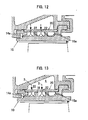
- FIG. 12 is a cross-sectional view showing a seventh embodiment of the structure of the present invention.
- vertical impingement cooling holes first impingement cooling holes 22
- first impingement cooling holes 22 are additionally provided to locally cool a location where the metal temperature increases.
- FIG. 13 is a cross-sectional view showing an eighth embodiment of the structure of the present invention.
- shroud members 10 each have a non-hole fin 18 which divides a cavity 2 into a plurality of sub-cavities.
- the non-hole fin 18 means a fin which does not have the second impingement cooling hole 12a.
- a test piece 5 which simulates a turbine shroud is produced.
- a metal surface temperature Tmg of the mainstream side of the test piece 5 is measured, and cooling efficiency ⁇ is calculated.
- FIG. 14B shows a structure (multiple-stage oblique impingement) of the present invention used in the test
- FIG. 14C shows a conventional example 1 (no pin, fin)
- FIG. 14D shows a conventional example 2 (with pins). Other conditions are the same for all structures.
- FIG. 15 shows test results.
- the horizontal axis represents the ratio (wc/wg) of a cooling air flow rate wc to a hot mainstream air flow rate wg, and the vertical axis represents the cooling efficiency ⁇ .
- the cooling efficiency of the present invention is high compared with the conventional examples 1 and 2.
- wc/wg in the present invention is about 0.6% while wc/wg in the conventional examples is about 1.3%.
- the amount of air required can be reduced to 1/2 or less with the cooling efficiency ⁇ being maintained.
- FIG. 16 is an illustrative diagram showing a relationship between a gap ⁇ h between a radial outward end of a hole fin 12 and an inner surface of a shroud cover 20, and a height h of the hole fin.
- the value ( ⁇ h/h) obtained by dividing the gap ⁇ h between the fin tip and the plate by the fin height h is set to range from 0 (no gap) to 0.2, and a calculation of a cooling air flow rate and a heat transfer analysis are performed.
- FIG. 17 shows the analysis results.
- the horizontal axis represents the axial length and the vertical axis represents the metal temperature of a gas passing surface (metal surface temperature on the mainstream side). Lines in the drawing represent results for ⁇ h/h ranging from 0 to 0.2.
- FIG. 18 is an illustrative diagram showing a relationship between the angle ⁇ of the second impingement cooling hole 12a and the height e of an impingement.
- FIG. 19 shows the test results.
- the horizontal axis represents the cooling air flow rate, and the vertical axis represents the average cooling efficiency.
- Solid circles and open circles in the graph represent the test results for 30° and 45°, respectively.
- FIGS. 20A, 20B, and 20C show the test results.
- the horizontal axis represents the cooling air flow rate and the vertical axis represents the average cooling efficiency.
- Solid circles and open circles in each graph represent the test results for the value of e/L being 0.13 and 0.26, respectively.
- the cooling efficiency when e/L is 0.13 is higher.
- the angle ⁇ preferably stands at or below about 45°.
- the value of e/L is preferably small, preferably 0.26 or less.
- the shroud cover 20 has the first impingement cooling hole 22 which allows cooling air 3 to be jetted in a cavity 2 formed between the shroud cover 20 and the shroud members 10, to cool the inner surface of the cavity by impingement
- the shroud members 10 each have the hole fin 12 which divides the cavity 2 into a plurality of sub-cavities
- the hole fin 12 has a second impingement cooling hole 12a which allows the cooling air 3 having flowed through the first impingement cooling hole 22 to be jetted obliquely toward the bottom surface of the adjacent sub-cavity.
Description
- The present invention relates to an impingement cooled structure that cools hot walls of a turbine shroud and a turbine end wall.
-
Prior art EP 0 709 550 A1 discloses an impingement cooled structure according to the preamble ofclaim 1. -
GB 2 166 805 A - A further impingement structure is known from prior art
US 5 048 288 A . Said prior art discloses an impingement structure comprising a cavity formed between a shroud cover and a shroud member. A plurality of cooling holes are provided in the shroud cover which communicate with the cavity and which allows cooling air to be jetted to an inside thereof. The shroud comprises two fins extending in a radial outward direction to an inner surface of the shroud cover to divide the cavity into three sub-cavities. The shroud further comprises a plurality of holes, which allow the cooling air to be discharged into the gas path. -
EP 1 124 039 A1 - In recent years, in order to improve thermal efficiency, an increase in the temperature of a gas turbine has been promoted. In this case, the turbine inlet temperature reaches about 1200°C to 1700°C. Under such high temperatures, metal turbine components need to be cooled so as not to exceed the service temperature limit of the materials thereof.
- An example of such turbine components includes a
turbine shroud 31 shown inFIG. 1 . As shown in a cross-sectional view ofFIG. 2 , a plurality ofturbine shrouds 31 are connected to each other in a circumferential direction to form a ring shape and surround fast-rotatingturbine blades 32 such that the ring shape is spaced from the tip surfaces of theturbine blades 32. With this structure, theturbine shrouds 31 have a function of controlling the flow rate of hot gas flowing through a gap between theshrouds 31 and theblades 32. - Hence, the inner surfaces of the
turbine shrouds 31 are always exposed to hot gas. Likewise, the inner surface of a turbine end wall is also exposed to hot gas. - In
FIG. 2 , thereference numeral 33 indicates a fixing portion, such as an inner surface of an engine, which allows theturbine shrouds 31 to be fixed thereto. Thereference numeral 34 indicates fixing hardware. - In order to cool hot walls of the aforementioned turbine shrouds and turbine end wall, for example, as shown in
FIGS. 3A and 3B , a conventionally employed cooled structure hasimpingement cooling holes 35, turbulence promoters 36 (or a smoothing flow path with fins),film cooling holes 37, or combination thereof. - However, cooling air used in such a cooled structure is usually high pressure air compressed by a compressor. Accordingly, there is a problem that the amount of the used cooling air directly affects engine performance.
- In view of this, in order to reduce the amount of used cooling air, there is proposed a configuration in which cooling air which is once used for impingement cooling is used again for impingement cooling (e.g.,
Patent Documents 1 and 2). - Specification of
US Patent No. 4,526,226 , "MULTIPLE-IMPINGEMENT COOLED STRUCTURE" - Specification of
US Patent No. 6,779,597 , "MULTIPLE IMPINGEMENT COOLED STRUCTURE" - As shown in
FIG. 4 , an impingement cooled structure ofPatent Document 1 includes: ashroud 47 having aninner surface 38, anouter surface 40,edges rib 46;flanges first baffle 56; asecond baffle 58; and fluid communication means. An upstream side of theouter surface 40 of theshroud 47 is cooled by impingement by means of cooling air which flows in the through holes of thefirst baffle 56. Furthermore, the same cooling air flows in the through holes of thesecond baffle 58 so as to cool the downstream side of theouter surface 40 of theshroud 47 by impingement. - As shown in
FIG. 5 , an impingement cooled structure ofPatent Document 2 includes: abase 62 having aninner surface 64 and anouter surface 66; afirst baffle 70; acavity 72; and asecond baffle 74. A downstream side of theouter surface 66 of thebase 62 is cooled by impingement by means of cooling air which flows in the through holes of thefirst baffle 70. Furthermore, the same cooling air flows in the through holes of thesecond baffle 74 so as to cool the upstream side of the outer surface of thebase 62 by impingement. - The impingement cooled structures of
Patent Documents Patent Documents - In order to solve the above problems, the present invention was made. Specifically, an object of the present invention is, therefore, to provide an impingement cooled structure capable of reducing the amount of cooling air which cools hot walls of a turbine shroud and a turbine end wall, with a structure as simple as a structure of shrouds prior to
Patent Documents
The aforementioned problems are solved by an impingement cooled structure according toclaim 1. Preferred embodiments are specified in the dependent claims. - According to the aforementioned configuration of the present invention, the shroud cover has the first impingement cooling hole which allows cooling air to be jetted in the cavity formed between the shroud cover and shroud members, to cool the inner surface of the cavity by impingement. The shroud members each have the hole fin which divides the cavity into a plurality of the sub-cavities, and the hole fin has the second impingement cooling hole which allows the cooling air having flowed through the first impingement cooling hole to be jetted obliquely toward the bottom surface of the adjacent sub-cavity. Therefore, it is possible to reduce the amount of cooling air for cooling hot walls of a turbine shroud and a turbine end wall, with the thickness of the shroud members being the same as that of conventional ones, without increasing radial thickness of the entire shroud, by the structure simply having the hole fins that is as simple as a conventional structure.
- That is, the cooled structure of the present invention is capable of significantly reducing the amount of cooling air by allowing cooling air, which is once used for impingement cooling to hot wall surfaces of the turbine shroud and end wall, to flow through an oblique hole (second impingement cooling hole) provided in the hole fin to re-use the cooling air for impingement cooling.
- Other objects and advantageous features of the present invention will become more apparent from the following description made with reference to the accompanying drawings.
-
-
FIG. 1 is a perspective view of a conventional turbine shroud; -
FIG. 2 is a cross-sectional view of the conventional turbine shroud; -
FIG. 3A is a cross-sectional view of a conventional cooled structure; -
FIG. 3B is a cross-sectional view of another conventional cooled structure; -
FIG. 4 is a cross-sectional view of an impingement cooled structure ofPatent Document 1; -
FIG. 5 is a cross-sectional view of an impingement cooled structure ofPatent Document 2; -
FIG. 6 shows a first embodiment of an impingement cooled structure according to the present invention; -
FIG. 7 is a cross-sectional view showing a second embodiment of the structure according to the present invention; -
FIG. 8 is a cross-sectional view showing a third embodiment of the structure according to the present invention; -
FIG. 9 is a cross-sectional view showing a fourth embodiment of the structure according to the present invention; -
FIG. 10 is a cross-sectional view showing a fifth embodiment of the structure according to the present invention; -
FIG. 11 is a cross-sectional view showing a sixth embodiment of the structure according to the present invention; -
FIG. 12 is a cross-sectional view showing a seventh embodiment of the structure according to the present invention; -
FIG. 13 is a cross-sectional view showing an eighth embodiment of the structure according to the present invention; -
FIG. 14A is a schematic illustration for description of cooling efficiency; -
FIG. 14B schematically shows the structure of the present invention; -
FIG. 14C schematically shows the structure of a conventional example; -
FIG. 14D schematically shows the structure of another conventional example; -
FIG. 15 is a graph showing test results which show a relationship between a ratio (wc/wg) of a cooling air flow rate wc to a hot mainstream air flow rate wg and a cooling efficiency η; -
FIG. 16 is an illustrative diagram showing a relationship between a gap Δh at a fin tip and a height h of a hole fin; -
FIG. 17 is a graph showing analysis results which show a relationship between an axial length and a metal temperature of a gas passing surface (metal surface temperature on a mainstream side); -
FIG. 18 is an illustrative diagram showing a relationship between an angle θ of a second impingement cooling hole and a height h of a hole fin; -
FIG. 19 is a graph showing test results which show a relationship between a cooling air flow rate and average cooling efficiency, with the angle θ being 30° and 45°; -
FIG. 20A is a graph showing test results which show a relationship between a cooling air flow rate and average cooling efficiency, with the angle θ being 45°, with e/L being 0.13 and 0.26; -
FIG. 20B is a graph showing test results which show a relationship between a cooling air flow rate and average cooling efficiency, with the angle θ being 37.5°, with e/L being 0.13 and 0.26; and -
FIG. 20C is a graph showing test results which show a relationship between a cooling air flow rate and average cooling efficiency, with the angle θ being 30°, with e/L being 0.13 and 0.26. - Preferred embodiments of the present invention will be described below with reference to the drawings. In the drawings, common parts are indicated by the same reference numerals, and overlapping description is omitted.
-
FIG. 6 is a diagram of a first embodiment showing an impingement cooled structure of the present invention. - In
FIG. 6 , mainstream gas (hot gas stream 1) which flows into a turbine undergoes adiabatic expansion when the mainstream gas performs work to aturbine blade 32. Accordingly, an upstream side of a turbine shroud is higher in temperature than a downstream side of the turbine shroud. Taking it into account, this embodiment is a basic configuration of the present invention for enhancing cooling of the upstream side. - In the drawing, the
reference numeral 32 indicates a fast-rotating turbine blade, thereference numeral 33 indicates a fixing portion, such as an inner surface of an engine, which allows a turbine shroud to be fixed thereto, and thereference numeral 34 indicates fixing hardware. - The impingement cooled structure of the present invention is constituted by a plurality of
shroud members 10 and ashroud cover 20. - The
shroud members 10 are disposed in a circumferential direction to constitute a ring-shaped shroud which surrounds thehot gas stream 1. Theshroud cover 20 is mounted on the radial outside faces of theshroud members 10 to constitute acavity 2 therebetween. - The
shroud members 10 each have aninner surface 11, anouter surface 13, anupstream flange 14 and adownstream flange 15. Theinner surface 11 extends along thehot gas stream 1 to be directly exposed to thehot gas stream 1. Theouter surface 13 is positioned at the outside of theinner surface 11 to constitute a bottom surface of thecavity 2. Theupstream flange 14 extends in the radial outward direction from the upstream side of thehot gas stream 1 to be fixed to the fixingportion 33. Thedownstream flange 15 extends in the radial outward direction from the downstream side of thehot gas stream 1 to be fixed to the fixingportion 33. - The
upstream flange 14 and thedownstream flange 15 are fixed to the fixingportion 33 to form a coolingair chamber 4 outside theshroud cover 20. - Furthermore, the
shroud members 10 each includehole fins 12 at its central portion at a radial outward side. Thehole fins 12 divide thecavity 2 into a plurality of sub-cavities 2a, 2b, and 2c. Although twohole fins 12 are used in the embodiment, a single or three ormore hole fins 12 may be used. The hole fin means a fin having a secondimpingement cooling hole 12a described later. - The
hole fins 12 extend in the radial outward direction from theouter surface 13 which constitutes the bottom surface of thecavity 2 to an inner surface (lower surface in the drawing) of theshroud cover 20 to divide thecavity 2 into a plurality of sub-cavities 2a, 2b, and 2c arranged adjacent to each other along the hot gas stream. - In addition, the
hole fins 12 each have a secondimpingement cooling hole 12a which allows coolingair 3 having flowed through a firstimpingement cooling hole 22 to be jetted obliquely toward the bottom surfaces of the adjacent sub-cavities 2b and 2c. - The
shroud cover 20 has the firstimpingement cooling hole 22 which communicates with thecavity 2 and allows the coolingair 3 to be jetted to the inside thereof so as to cool the inner surface of the cavity by impingement. The firstimpingement cooling hole 22 in the embodiment communicates with the sub-cavity 2a positioned on the most upstream side along thehot gas stream 1, and is a through hole perpendicular to thehot gas stream 1. - However, the present invention is not limited to this configuration, and the first
impingement cooling hole 22 may communicates with themid sub-cavity 2b or the sub-cavity 2c on the downstream side. - In the embodiment, the
upstream flange 14 and thedownstream flange 15 have thirdimpingement cooling holes respective flanges cavity 2. - In the impingement cooled structure of
FIG. 6 , the high-pressure cooling air 3 first flows through the firstimpingement cooling hole 22 and impinges perpendicularly upon a portion of the outer surface 13 (hot wall) which constitutes the bottom surface of the sub-cavity 2a to thereby absorb heat from the hot wall. Then, the coolingair 3 reaches a secondimpingement cooling hole 12a on the upstream side while exchanging heat with ahole fin 12, flows through thehole 12a, and impinges again upon a hot wall (a portion of theouter surface 13 which constitutes the bottom surface of the sub-cavity 2b) to thereby absorb heat from the wall. At the same time, part of the coolingair 3 reaches the thirdimpingement cooling hole 14a while exchanging heat with theupstream flange 14, flows through the hole, and impinges upon the outer surface of the flange, and then exits to a mainstream while absorbing heat from the wall. - Furthermore, the cooling
air 3 having flowed in the sub-cavity 2b reaches a secondimpingement cooling hole 12a on the downstream side while exchanging heat with ahole fin 12, flows through thehole 12a, and impinges again upon a hot wall (a portion of theouter surface 13 which constitutes the bottom surface of the sub-cavity 2c) to thereby absorb heat from the wall. Finally, the coolingair 3 reaches the thirdimpingement cooling hole 15a while exchanging heat with thedownstream flange 15, flows through thehole 15a, and impinges upon the outer surface of the flange to thereby absorb heat from the wall, and then exit to the mainstream. - According to the aforementioned configuration, in the impingement cooled structure of the present invention, the cooling performance is improved by the effects obtained by the hole fins as well as re-use of cooling air. Accordingly, in the cooled structure of the present invention, even if the used amount of cooling air is reduced to about 1/2 or less than the used amount of cooling air in conventional impingement cooling, it is possible to maintain a metal temperature equivalent to that in conventional impingement cooling.
-
FIG. 7 is a cross-sectional view showing a second embodiment of the structure of the present invention. In the second embodiment, compared with the first embodiment (basic configuration), asingle hole fin 12 is used, a thirdimpingement cooling hole 14a is not formed in theupstream flange 14, and only a thirdimpingement cooling hole 15a is formed in adownstream flange 15. The other configuration of the second embodiment may be the same as that of the first embodiment (basic configuration). - By the configuration of the second embodiment, the number of stages of impingement cooling can be reduced. Alternatively, in contrast, the number of stages of impingement cooling may be increased by increasing the number of
hole fins 12. -
FIGS. 8 and 9 are cross-sectional views showing third and fourth embodiments, respectively, of the structure of the present invention. In the third and fourth embodiments, compared with the first embodiment (basic configuration), a location where impingement cooling by cooling air is first performed is changed. -
FIG. 10 is a cross-sectional view showing a embodiment of the structure of the present invention. In the fifth embodiment, compared with the first embodiment (basic configuration), a thirdimpingement cooling hole 14a and a thirdimpingement cooling hole 15a are omitted. Instead,shroud members 10 each havefilm cooling holes cooling air 3 to be jetted obliquely toward aninner surface 11 from cavity 2 (sub-cavities 2a, 2b, and 2c). - By this configuration of the fifth embodiment, cooling can be enhanced by the film cooling holes in accordance with design requirements, for example.
-
FIG. 11 is a cross-sectional view showing a sixth embodiment of the structure of the present invention. In the sixth embodiment, compared with the first embodiment (basic configuration),turbulence promoters 17 are provided on the bottom surface of the cavity 2 (sub-cavities 2a, 2b, and 2c). Theturbulence promoters 17 are preferably pins, projections, or the like, which have a function of increasing the heat transfer coefficient by interrupting a flow. Other than the turbulence promoters, for the purpose of increasing a heat transfer area, larger projections, pins, or the like may be provided. - By this configuration of the sixth embodiment, it is possible to enhance cooling by increasing the heat transfer coefficient and the heat transfer area.
-
FIG. 12 is a cross-sectional view showing a seventh embodiment of the structure of the present invention. In the seventh embodiment, compared with the first embodiment (basic configuration), vertical impingement cooling holes (first impingement cooling holes 22) are additionally provided to locally cool a location where the metal temperature increases. -
FIG. 13 is a cross-sectional view showing an eighth embodiment of the structure of the present invention. In the eighth embodiment, compared with the first embodiment (basic configuration),shroud members 10 each have anon-hole fin 18 which divides acavity 2 into a plurality of sub-cavities. By thenon-hole fin 18, the flow path of coolingair 3 is divided into two flow paths. The non-hole fin means a fin which does not have the secondimpingement cooling hole 12a. - By this configuration of the eighth embodiment, although the amount of cooling air is increased, cooling can be further enhanced.
- Test results obtained by comparing the cooling efficiency of the aforementioned structure of the present invention against that of conventional examples are described below.
- As schematically shown in
FIG. 14A , atest piece 5 which simulates a turbine shroud is produced. In a state in whichhot gas 1 is flowed over one surface and coolingair 3 is flowed over the other surface, a metal surface temperature Tmg of the mainstream side of thetest piece 5 is measured, and cooling efficiency η is calculated. - The cooling efficiency η is defined by the formula of η=(Tg-Tmg)/(Tg-Tc) ... (1), where Tg is the hot mainstream air temperature and Tc is the cooling air temperature.
-
FIG. 14B shows a structure (multiple-stage oblique impingement) of the present invention used in the test,FIG. 14C shows a conventional example 1 (no pin, fin), andFIG. 14D shows a conventional example 2 (with pins). Other conditions are the same for all structures. -
FIG. 15 shows test results. The horizontal axis represents the ratio (wc/wg) of a cooling air flow rate wc to a hot mainstream air flow rate wg, and the vertical axis represents the cooling efficiency η. - From the graph, it can be seen that the cooling efficiency of the present invention is high compared with the conventional examples 1 and 2. For example, when a cooling efficiency of 0.5 is required, wc/wg in the present invention is about 0.6% while wc/wg in the conventional examples is about 1.3%. Thus, the amount of air required can be reduced to 1/2 or less with the cooling efficiency η being maintained.
- Next, in the structure of the present invention, the influence of a gap at a fin tip is tested.
-
FIG. 16 is an illustrative diagram showing a relationship between a gap Δh between a radial outward end of ahole fin 12 and an inner surface of ashroud cover 20, and a height h of the hole fin. In the drawing, the value (Δh/h) obtained by dividing the gap Δh between the fin tip and the plate by the fin height h is set to range from 0 (no gap) to 0.2, and a calculation of a cooling air flow rate and a heat transfer analysis are performed. -
FIG. 17 shows the analysis results. The horizontal axis represents the axial length and the vertical axis represents the metal temperature of a gas passing surface (metal surface temperature on the mainstream side). Lines in the drawing represent results for Δh/h ranging from 0 to 0.2. - From the graph, it is found that the temperature of the turbine shroud stands below an allowable value when Δh/h stands at or below about 0.2.
- Next, in the structure of the present invention, the influence of the angle of a second
impingement cooling hole 12a is tested. -
FIG. 18 is an illustrative diagram showing a relationship between the angle θ of the secondimpingement cooling hole 12a and the height e of an impingement. In the drawing, a cooling performance test is conducted under the following conditions: the angle θ = 30° and 45°, and h/L = 0.13 and 0.26, where h is the height of an impingement, and L is cooling chamber length. -
FIG. 19 shows the test results. The horizontal axis represents the cooling air flow rate, and the vertical axis represents the average cooling efficiency. Solid circles and open circles in the graph represent the test results for 30° and 45°, respectively. - From the graph, it is found that even if the angle is changed, the cooling efficiency is not much affected thereby.
- Next, under the same conditions as those in
FIG. 18 , the influence of an impingement height e is tested. -
FIGS. 20A, 20B, and 20C show the test results. The horizontal axis represents the cooling air flow rate and the vertical axis represents the average cooling efficiency. Solid circles and open circles in each graph represent the test results for the value of e/L being 0.13 and 0.26, respectively. - From the graphs, it can be seen that, when the value of e/L (where e is the impingement height, and L is cooling chamber length) is changed, the cooling efficiency when e/L is 0.13 is higher. However, when the angel θ of the second
impingement cooling hole 12a is made large, the shroud thickness needs to be increased, resulting in undesirable effects such as an increase in weight and an increase in thermal stress at the time of operation. Therefore, the angle θ preferably stands at or below about 45°. In addition, the value of e/L is preferably small, preferably 0.26 or less. - As described above, according to the configuration of the present invention, the
shroud cover 20 has the firstimpingement cooling hole 22 which allows coolingair 3 to be jetted in acavity 2 formed between theshroud cover 20 and theshroud members 10, to cool the inner surface of the cavity by impingement, theshroud members 10 each have thehole fin 12 which divides thecavity 2 into a plurality of sub-cavities, and thehole fin 12 has a secondimpingement cooling hole 12a which allows the coolingair 3 having flowed through the firstimpingement cooling hole 22 to be jetted obliquely toward the bottom surface of the adjacent sub-cavity. - Therefore, it is possible to reduce the amount of cooling air for cooling hot walls of a turbine shroud and a turbine end wall, with the thickness of the
shroud members 10 being the same as that of conventional ones, without increasing radial thickness of the entire shroud, by the structure simply having thehole fins 12 that is as simple as a conventional structure.
Claims (8)
- An impingement cooled structure comprising:a plurality of shroud members (10) disposed in a circumferential direction to constitute a ring-shaped shroud surrounding a hot gas stream (1); anda shroud cover (20) mounted on radial outside faces of the shroud members (10) to form a cavity (2) therebetween,the shroud cover (20) having a first impingement cooling hole (22) which communicates with the cavity (2) and allows cooling air (3) to be jetted to an inside thereof so as to cool an inner surface (11) of the cavity (2) by impingement,the shroud members (10) each having a hole fin (12),the hole fin (12) dividing the cavity (2) into a plurality of sub-cavities (2a, 2b, 2c),the hole fin (12) having a second impingement cooling hole (12a) which allows the cooling air (3) having flowed through the first impingement cooling hole (22) to be jetted obliquely toward a bottom surface of the sub-cavity (2b, 2c) adjacent thereto
characterized in that
the hole fin (12) extending in a radial outward direction to an inner surface of the shroud cover (20) from the outer surface (13) constituting the bottom surface of the cavity (2) to divide the cavity (2) into the plurality of sub-cavities (2a, 2b, 2c) adjacent to each other along the hot gas stream (1). - An impingement cooled structure according to claim 1, the shroud members (10) each having: an inner surface (11) extending along the hot gas stream (1) to be directly exposed to the hot gas stream (1); an outer surface (13) positioned at an outside of the inner surface (11) to constitute a bottom surface of the cavity (2); an upstream flange (14) extending in a radial outward direction from an upstream side of the hot gas stream (1) to be fixed to a fixing portion (33); and a downstream flange (15) extending in a radial outward direction from a downstream side of the hot gas stream (1) to be fixed to the fixing portion (33),
the upstream flange (14) and the downstream flange (15) being provided for forming a cooling air chamber (4) outside the shroud cover (20). - An impingement cooled structure according to claim 2, the upstream flange (14) and/or the downstream flange (15) having a third impingement cooling hole (14a, 15a) which allows the cooling air (3) to be jetted toward an outer surface of the flange (14, 15) from the cavity (2).
- An impingement cooled structure according to claim 2, the shroud members (10) each having a film cooling hole (16a, 16b) which allows the cooling air (3) to be jetted toward the inner surface (11) of the shroud member (10) from the cavity (2).
- An impingement cooled structure according to claim 1, comprising a turbulence promoter (17), a projection or a pin on the bottom surface of the cavity (2), the turbulence promoter (17) promoting turbulence, the projection or the pin increasing a heat transfer area.
- An impingement cooled structure according to claim 1, the shroud members (10) each having a non-hole fin (18) which divides the cavity (2) into a plurality of sub-cavities and divides a flow path of the cooling air (3) into two or more flow paths.
- An impingement cooled structure according to claim 2, a gap being formed between a radial outward end of the hole fin (12) and the inner surface of the shroud cover (20), a height Δh of the gap being 0.2 or less times as high as a height h of the hole fin (12).
- An impingement cooled structure according to claim 2, an angle (θ) of the second impingement cooling hole (12a) to a bottom surface of a sub-cavity is 45° or less, an impingement height e being 0.26 or less times as long as a length L of the sub-cavity (2a, 2b, 2c) in a flow path direction.
Applications Claiming Priority (2)
| Application Number | Priority Date | Filing Date | Title |
|---|---|---|---|
| JP2006056084 | 2006-03-02 | ||
| PCT/JP2007/053486 WO2007099895A1 (en) | 2006-03-02 | 2007-02-26 | Impingement cooling structure |
Publications (3)
| Publication Number | Publication Date |
|---|---|
| EP1990507A1 EP1990507A1 (en) | 2008-11-12 |
| EP1990507A4 EP1990507A4 (en) | 2014-04-23 |
| EP1990507B1 true EP1990507B1 (en) | 2015-04-15 |
Family
ID=38459002
Family Applications (1)
| Application Number | Title | Priority Date | Filing Date |
|---|---|---|---|
| EP07714918.5A Expired - Fee Related EP1990507B1 (en) | 2006-03-02 | 2007-02-26 | Impingement cooling structure |
Country Status (5)
| Country | Link |
|---|---|
| US (1) | US8137056B2 (en) |
| EP (1) | EP1990507B1 (en) |
| JP (1) | JP4845957B2 (en) |
| CA (1) | CA2644099C (en) |
| WO (1) | WO2007099895A1 (en) |
Cited By (1)
| Publication number | Priority date | Publication date | Assignee | Title |
|---|---|---|---|---|
| EP3246533B1 (en) * | 2016-05-18 | 2023-06-28 | Raytheon Technologies Corporation | Shaped cooling passages for turbine blade outer air seal |
Families Citing this family (55)
| Publication number | Priority date | Publication date | Assignee | Title |
|---|---|---|---|---|
| US8439629B2 (en) * | 2007-03-01 | 2013-05-14 | United Technologies Corporation | Blade outer air seal |
| US8177492B2 (en) * | 2008-03-04 | 2012-05-15 | United Technologies Corporation | Passage obstruction for improved inlet coolant filling |
| CH699232A1 (en) * | 2008-07-22 | 2010-01-29 | Alstom Technology Ltd | Gas turbine. |
| EP2184445A1 (en) * | 2008-11-05 | 2010-05-12 | Siemens Aktiengesellschaft | Axial segmented vane support for a gas turbine |
| GB0904118D0 (en) | 2009-03-11 | 2009-04-22 | Rolls Royce Plc | An impingement cooling arrangement for a gas turbine engine |
| US9145779B2 (en) * | 2009-03-12 | 2015-09-29 | United Technologies Corporation | Cooling arrangement for a turbine engine component |
| EP3006678B1 (en) * | 2009-08-24 | 2017-12-20 | Mitsubishi Heavy Industries, Ltd. | Ring segment with cooling system and gas turbine |
| JP2011208624A (en) * | 2010-03-31 | 2011-10-20 | Hitachi Ltd | Cooling structure for high-temperature member |
| FR2962484B1 (en) * | 2010-07-08 | 2014-04-25 | Snecma | TURBOMACHINE TURBINE RING SECTOR EQUIPPED WITH CLOISON |
| US9458855B2 (en) | 2010-12-30 | 2016-10-04 | Rolls-Royce North American Technologies Inc. | Compressor tip clearance control and gas turbine engine |
| US8876458B2 (en) * | 2011-01-25 | 2014-11-04 | United Technologies Corporation | Blade outer air seal assembly and support |
| US20130028704A1 (en) * | 2011-07-26 | 2013-01-31 | Thibodeau Anne-Marie B | Blade outer air seal with passage joined cavities |
| US8826668B2 (en) * | 2011-08-02 | 2014-09-09 | Siemens Energy, Inc. | Two stage serial impingement cooling for isogrid structures |
| US9238970B2 (en) * | 2011-09-19 | 2016-01-19 | United Technologies Corporation | Blade outer air seal assembly leading edge core configuration |
| US20140130504A1 (en) * | 2012-11-12 | 2014-05-15 | General Electric Company | System for cooling a hot gas component for a combustor of a gas turbine |
| US9719362B2 (en) | 2013-04-24 | 2017-08-01 | Honeywell International Inc. | Turbine nozzles and methods of manufacturing the same |
| EP2835500A1 (en) * | 2013-08-09 | 2015-02-11 | Siemens Aktiengesellschaft | Insert element and gas turbine |
| EP2860358A1 (en) | 2013-10-10 | 2015-04-15 | Alstom Technology Ltd | Arrangement for cooling a component in the hot gas path of a gas turbine |
| US9657642B2 (en) | 2014-03-27 | 2017-05-23 | Honeywell International Inc. | Turbine sections of gas turbine engines with dual use of cooling air |
| US20160047549A1 (en) * | 2014-08-15 | 2016-02-18 | Rolls-Royce Corporation | Ceramic matrix composite components with inserts |
| US10280785B2 (en) * | 2014-10-31 | 2019-05-07 | General Electric Company | Shroud assembly for a turbine engine |
| EP3023596B1 (en) * | 2014-11-20 | 2019-01-02 | United Technologies Corporation | Internally cooled turbine platform |
| EP3034803A1 (en) | 2014-12-16 | 2016-06-22 | Rolls-Royce Corporation | Hanger system for a turbine engine component |
| EP3048262A1 (en) * | 2015-01-20 | 2016-07-27 | Alstom Technology Ltd | Wall for a hot gas channel in a gas turbine |
| US10221715B2 (en) * | 2015-03-03 | 2019-03-05 | Rolls-Royce North American Technologies Inc. | Turbine shroud with axially separated pressure compartments |
| US9849510B2 (en) | 2015-04-16 | 2017-12-26 | General Electric Company | Article and method of forming an article |
| US9976441B2 (en) | 2015-05-29 | 2018-05-22 | General Electric Company | Article, component, and method of forming an article |
| EP3121387B1 (en) * | 2015-07-24 | 2018-12-26 | Rolls-Royce Corporation | A gas turbine engine with a seal segment |
| US10253986B2 (en) | 2015-09-08 | 2019-04-09 | General Electric Company | Article and method of forming an article |
| US10087776B2 (en) | 2015-09-08 | 2018-10-02 | General Electric Company | Article and method of forming an article |
| US10739087B2 (en) | 2015-09-08 | 2020-08-11 | General Electric Company | Article, component, and method of forming an article |
| US20170198602A1 (en) * | 2016-01-11 | 2017-07-13 | General Electric Company | Gas turbine engine with a cooled nozzle segment |
| RU2706210C2 (en) | 2016-01-25 | 2019-11-14 | Ансалдо Энерджиа Свитзерлэнд Аг | Stator thermal shield for gas turbine, gas turbine with such stator thermal shield and stator thermal shield cooling method |
| US10184343B2 (en) | 2016-02-05 | 2019-01-22 | General Electric Company | System and method for turbine nozzle cooling |
| US10344611B2 (en) * | 2016-05-19 | 2019-07-09 | United Technologies Corporation | Cooled hot section components for a gas turbine engine |
| GB201612646D0 (en) * | 2016-07-21 | 2016-09-07 | Rolls Royce Plc | An air cooled component for a gas turbine engine |
| JP6821386B2 (en) * | 2016-10-21 | 2021-01-27 | 三菱重工業株式会社 | Rotating machine |
| US10370983B2 (en) | 2017-07-28 | 2019-08-06 | Rolls-Royce Corporation | Endwall cooling system |
| US10767490B2 (en) * | 2017-09-08 | 2020-09-08 | Raytheon Technologies Corporation | Hot section engine components having segment gap discharge holes |
| KR102000830B1 (en) | 2017-09-11 | 2019-07-16 | 두산중공업 주식회사 | Gas Turbine Blade |
| US20190218925A1 (en) * | 2018-01-18 | 2019-07-18 | General Electric Company | Turbine engine shroud |
| US11268402B2 (en) * | 2018-04-11 | 2022-03-08 | Raytheon Technologies Corporation | Blade outer air seal cooling fin |
| EP3564484A1 (en) | 2018-05-04 | 2019-11-06 | Siemens Aktiengesellschaft | Hot gas component wall |
| US10934876B2 (en) * | 2018-07-18 | 2021-03-02 | Raytheon Technologies Corporation | Blade outer air seal AFT hook retainer |
| US10989068B2 (en) | 2018-07-19 | 2021-04-27 | General Electric Company | Turbine shroud including plurality of cooling passages |
| US10837315B2 (en) * | 2018-10-25 | 2020-11-17 | General Electric Company | Turbine shroud including cooling passages in communication with collection plenums |
| KR102178956B1 (en) * | 2019-02-26 | 2020-11-16 | 두산중공업 주식회사 | Turbine vane and ring segment and gas turbine comprising the same |
| CN110145373B (en) * | 2019-05-10 | 2022-04-15 | 沈阳航空航天大学 | Non-uniform transverse and longitudinal groove turbine outer ring structure |
| CN110332023B (en) * | 2019-07-16 | 2021-12-28 | 中国航发沈阳发动机研究所 | End face sealing structure with cooling function |
| US11035248B1 (en) * | 2019-11-25 | 2021-06-15 | General Electric Company | Unitary body turbine shrouds including shot peen screens integrally formed therein and turbine systems thereof |
| JP6799702B1 (en) * | 2020-03-19 | 2020-12-16 | 三菱パワー株式会社 | Static blade and gas turbine |
| US11365645B2 (en) * | 2020-10-07 | 2022-06-21 | Pratt & Whitney Canada Corp. | Turbine shroud cooling |
| KR102502652B1 (en) * | 2020-10-23 | 2023-02-21 | 두산에너빌리티 주식회사 | Array impingement jet cooling structure with wavy channel |
| CN113123833B (en) * | 2021-03-26 | 2022-05-10 | 北京航空航天大学 | Turbine outer ring block air supply structure with separated air supply |
| CN113638777B (en) * | 2021-09-10 | 2023-09-15 | 中国航发湖南动力机械研究所 | Turbine outer ring clamp, cooling structure of turbine outer ring, turbine and engine |
Family Cites Families (15)
| Publication number | Priority date | Publication date | Assignee | Title |
|---|---|---|---|---|
| CH584833A5 (en) * | 1975-05-16 | 1977-02-15 | Bbc Brown Boveri & Cie | |
| JPS51147805A (en) * | 1975-06-11 | 1976-12-18 | Norio Takahashi | Foundation continuously supporting rails |
| US4526226A (en) | 1981-08-31 | 1985-07-02 | General Electric Company | Multiple-impingement cooled structure |
| FR2724973B1 (en) * | 1982-12-31 | 1996-12-13 | Snecma | DEVICE FOR SEALING MOBILE BLADES OF A TURBOMACHINE WITH REAL-TIME ACTIVE GAME CONTROL AND METHOD FOR DETERMINING SAID DEVICE |
| US4650394A (en) * | 1984-11-13 | 1987-03-17 | United Technologies Corporation | Coolable seal assembly for a gas turbine engine |
| US5048288A (en) * | 1988-12-20 | 1991-09-17 | United Technologies Corporation | Combined turbine stator cooling and turbine tip clearance control |
| US5584651A (en) * | 1994-10-31 | 1996-12-17 | General Electric Company | Cooled shroud |
| JP3824324B2 (en) | 1994-10-31 | 2006-09-20 | ウエスチングハウス・エレクトリック・コーポレイション | Gas turbine blades with cooling platform |
| JPH11200805A (en) | 1998-01-14 | 1999-07-27 | Toshiba Corp | Cooling method for structural element, structural element with cooling passage, and gas turbine blade with cooling passage |
| US6146091A (en) * | 1998-03-03 | 2000-11-14 | Mitsubishi Heavy Industries, Ltd. | Gas turbine cooling structure |
| JP3631898B2 (en) * | 1998-03-03 | 2005-03-23 | 三菱重工業株式会社 | Cooling structure of split ring in gas turbine |
| JPH11257003A (en) | 1998-03-06 | 1999-09-21 | Mitsubishi Heavy Ind Ltd | Impingement cooling device |
| EP1124039A1 (en) * | 2000-02-09 | 2001-08-16 | General Electric Company | Impingement cooling apparatus for a gas turbine shroud system |
| US6779597B2 (en) | 2002-01-16 | 2004-08-24 | General Electric Company | Multiple impingement cooled structure |
| US7033138B2 (en) | 2002-09-06 | 2006-04-25 | Mitsubishi Heavy Industries, Ltd. | Ring segment of gas turbine |
-
2007
- 2007-02-26 US US12/281,369 patent/US8137056B2/en active Active
- 2007-02-26 EP EP07714918.5A patent/EP1990507B1/en not_active Expired - Fee Related
- 2007-02-26 CA CA2644099A patent/CA2644099C/en not_active Expired - Fee Related
- 2007-02-26 WO PCT/JP2007/053486 patent/WO2007099895A1/en active Application Filing
- 2007-02-26 JP JP2008502758A patent/JP4845957B2/en active Active
Cited By (1)
| Publication number | Priority date | Publication date | Assignee | Title |
|---|---|---|---|---|
| EP3246533B1 (en) * | 2016-05-18 | 2023-06-28 | Raytheon Technologies Corporation | Shaped cooling passages for turbine blade outer air seal |
Also Published As
| Publication number | Publication date |
|---|---|
| JP4845957B2 (en) | 2011-12-28 |
| US20090035125A1 (en) | 2009-02-05 |
| EP1990507A4 (en) | 2014-04-23 |
| US8137056B2 (en) | 2012-03-20 |
| WO2007099895A1 (en) | 2007-09-07 |
| JPWO2007099895A1 (en) | 2009-07-16 |
| CA2644099A1 (en) | 2007-09-07 |
| EP1990507A1 (en) | 2008-11-12 |
| CA2644099C (en) | 2013-12-31 |
Similar Documents
| Publication | Publication Date | Title |
|---|---|---|
| EP1990507B1 (en) | Impingement cooling structure | |
| CA2372984C (en) | Gas turbine segmental ring | |
| JP6928995B2 (en) | Tapered cooling channel for wings | |
| US8667682B2 (en) | Method of fabricating a nearwall nozzle impingement cooled component for an internal combustion engine | |
| EP2825748B1 (en) | Cooling channel for a gas turbine engine and gas turbine engine | |
| US10787911B2 (en) | Cooling configuration for a gas turbine engine airfoil | |
| US8246307B2 (en) | Blade for a rotor | |
| US8414263B1 (en) | Turbine stator vane with near wall integrated micro cooling channels | |
| US9133717B2 (en) | Cooling structure of turbine airfoil | |
| US9896942B2 (en) | Cooled turbine guide vane or blade for a turbomachine | |
| US6746209B2 (en) | Methods and apparatus for cooling gas turbine engine nozzle assemblies | |
| EP3124745B1 (en) | Turbo-engine component with film cooled wall | |
| JP2013508610A (en) | Blades incorporating tapered cooling structures that form cooling channels | |
| US9163518B2 (en) | Full coverage trailing edge microcircuit with alternating converging exits | |
| KR20150110367A (en) | Turbine vane with cooled fillet | |
| GB2301405A (en) | Gas turbine guide nozzle vane | |
| JP6906907B2 (en) | Cooling structure for fixed blades | |
| JP4234650B2 (en) | Cooled gas turbine engine blades | |
| JP2001521599A (en) | Turbine blade, its use and method of cooling turbine blade | |
| EP3508692B1 (en) | Airfoil with rib communication openings | |
| JPS597711A (en) | Cooling device of turbine shell |
Legal Events
| Date | Code | Title | Description |
|---|---|---|---|
| PUAI | Public reference made under article 153(3) epc to a published international application that has entered the european phase |
Free format text: ORIGINAL CODE: 0009012 |
|
| 17P | Request for examination filed |
Effective date: 20080901 |
|
| AK | Designated contracting states |
Kind code of ref document: A1 Designated state(s): FR GB |
|
| DAX | Request for extension of the european patent (deleted) | ||
| RBV | Designated contracting states (corrected) |
Designated state(s): FR GB |
|
| A4 | Supplementary search report drawn up and despatched |
Effective date: 20140320 |
|
| RIC1 | Information provided on ipc code assigned before grant |
Ipc: F01D 25/24 20060101AFI20140314BHEP Ipc: F01D 11/08 20060101ALN20140314BHEP Ipc: F02C 7/18 20060101ALI20140314BHEP |
|
| 17Q | First examination report despatched |
Effective date: 20140916 |
|
| GRAP | Despatch of communication of intention to grant a patent |
Free format text: ORIGINAL CODE: EPIDOSNIGR1 |
|
| RIC1 | Information provided on ipc code assigned before grant |
Ipc: F01D 11/08 20060101ALN20141010BHEP Ipc: F02C 7/18 20060101ALI20141010BHEP Ipc: F01D 25/24 20060101AFI20141010BHEP |
|
| INTG | Intention to grant announced |
Effective date: 20141104 |
|
| GRAS | Grant fee paid |
Free format text: ORIGINAL CODE: EPIDOSNIGR3 |
|
| GRAA | (expected) grant |
Free format text: ORIGINAL CODE: 0009210 |
|
| AK | Designated contracting states |
Kind code of ref document: B1 Designated state(s): FR GB |
|
| REG | Reference to a national code |
Ref country code: GB Ref legal event code: FG4D |
|
| REG | Reference to a national code |
Ref country code: FR Ref legal event code: PLFP Year of fee payment: 10 |
|
| PLBE | No opposition filed within time limit |
Free format text: ORIGINAL CODE: 0009261 |
|
| STAA | Information on the status of an ep patent application or granted ep patent |
Free format text: STATUS: NO OPPOSITION FILED WITHIN TIME LIMIT |
|
| 26N | No opposition filed |
Effective date: 20160118 |
|
| REG | Reference to a national code |
Ref country code: FR Ref legal event code: PLFP Year of fee payment: 11 |
|
| REG | Reference to a national code |
Ref country code: FR Ref legal event code: PLFP Year of fee payment: 12 |
|
| PGFP | Annual fee paid to national office [announced via postgrant information from national office to epo] |
Ref country code: FR Payment date: 20210113 Year of fee payment: 15 |
|
| PGFP | Annual fee paid to national office [announced via postgrant information from national office to epo] |
Ref country code: GB Payment date: 20210217 Year of fee payment: 15 |
|
| GBPC | Gb: european patent ceased through non-payment of renewal fee |
Effective date: 20220226 |
|
| PG25 | Lapsed in a contracting state [announced via postgrant information from national office to epo] |
Ref country code: FR Free format text: LAPSE BECAUSE OF NON-PAYMENT OF DUE FEES Effective date: 20220228 |
|
| PG25 | Lapsed in a contracting state [announced via postgrant information from national office to epo] |
Ref country code: GB Free format text: LAPSE BECAUSE OF NON-PAYMENT OF DUE FEES Effective date: 20220226 |