EP3203009A1 - Bohrrohr, bohrrohranordnung,bohrrohrschuh, werkzeuganordnung mit einem bohrrohrschuh und bohranordnung - Google Patents
Bohrrohr, bohrrohranordnung,bohrrohrschuh, werkzeuganordnung mit einem bohrrohrschuh und bohranordnung Download PDFInfo
- Publication number
- EP3203009A1 EP3203009A1 EP16206335.8A EP16206335A EP3203009A1 EP 3203009 A1 EP3203009 A1 EP 3203009A1 EP 16206335 A EP16206335 A EP 16206335A EP 3203009 A1 EP3203009 A1 EP 3203009A1
- Authority
- EP
- European Patent Office
- Prior art keywords
- casing
- attachment means
- shoulder
- groove
- end portion
- Prior art date
- Legal status (The legal status is an assumption and is not a legal conclusion. Google has not performed a legal analysis and makes no representation as to the accuracy of the status listed.)
- Withdrawn
Links
- 230000007423 decrease Effects 0.000 claims abstract description 7
- 239000000463 material Substances 0.000 claims description 32
- 238000003466 welding Methods 0.000 claims description 21
- 238000005553 drilling Methods 0.000 claims description 16
- 239000004033 plastic Substances 0.000 claims description 14
- 229920003023 plastic Polymers 0.000 claims description 14
- -1 polyethylene Polymers 0.000 claims description 4
- 229920000098 polyolefin Polymers 0.000 claims description 3
- 239000004698 Polyethylene Substances 0.000 claims description 2
- 239000004743 Polypropylene Substances 0.000 claims description 2
- 229920000573 polyethylene Polymers 0.000 claims description 2
- 229920001155 polypropylene Polymers 0.000 claims description 2
- 230000003247 decreasing effect Effects 0.000 claims 1
- 238000013016 damping Methods 0.000 description 13
- 230000000295 complement effect Effects 0.000 description 7
- 238000010276 construction Methods 0.000 description 4
- 230000008878 coupling Effects 0.000 description 4
- 238000010168 coupling process Methods 0.000 description 4
- 238000005859 coupling reaction Methods 0.000 description 4
- 239000013013 elastic material Substances 0.000 description 3
- XEEYBQQBJWHFJM-UHFFFAOYSA-N Iron Chemical compound [Fe] XEEYBQQBJWHFJM-UHFFFAOYSA-N 0.000 description 2
- 229910000831 Steel Inorganic materials 0.000 description 2
- 238000004519 manufacturing process Methods 0.000 description 2
- 239000010959 steel Substances 0.000 description 2
- 238000005336 cracking Methods 0.000 description 1
- 229920001971 elastomer Polymers 0.000 description 1
- 239000000806 elastomer Substances 0.000 description 1
- 239000011440 grout Substances 0.000 description 1
- 239000012535 impurity Substances 0.000 description 1
- 238000003780 insertion Methods 0.000 description 1
- 230000037431 insertion Effects 0.000 description 1
- 229910052742 iron Inorganic materials 0.000 description 1
- 239000002184 metal Substances 0.000 description 1
- 229910052751 metal Inorganic materials 0.000 description 1
- 230000000149 penetrating effect Effects 0.000 description 1
- 238000009877 rendering Methods 0.000 description 1
- 229920001169 thermoplastic Polymers 0.000 description 1
- 239000012815 thermoplastic material Substances 0.000 description 1
- 239000004416 thermosoftening plastic Substances 0.000 description 1
- XLYOFNOQVPJJNP-UHFFFAOYSA-N water Substances O XLYOFNOQVPJJNP-UHFFFAOYSA-N 0.000 description 1
- 239000013585 weight reducing agent Substances 0.000 description 1
Images


Classifications
-
- E—FIXED CONSTRUCTIONS
- E21—EARTH OR ROCK DRILLING; MINING
- E21B—EARTH OR ROCK DRILLING; OBTAINING OIL, GAS, WATER, SOLUBLE OR MELTABLE MATERIALS OR A SLURRY OF MINERALS FROM WELLS
- E21B17/00—Drilling rods or pipes; Flexible drill strings; Kellies; Drill collars; Sucker rods; Cables; Casings; Tubings
- E21B17/02—Couplings; joints
- E21B17/04—Couplings; joints between rod or the like and bit or between rod and rod or the like
- E21B17/046—Couplings; joints between rod or the like and bit or between rod and rod or the like with ribs, pins, or jaws, and complementary grooves or the like, e.g. bayonet catches
Definitions
- the present disclosure relates to a casing pipe and a casing pipe arrangement used in drilling.
- the present disclosure further concerns a corresponding casing shoes and an arrangement having a casing shoe, and a drill arrangement.
- casing pipes in drilling for various purposes.
- a casing pipe may be arranged to enhance the structural integrity of the drill hole, thus enabling the drill string and drill tools to be removed from the drill hole.
- a casing pipe may also be used as a casing for inserting piping or tubing into the drill hole after the drilling, or for injecting grout into the hole.
- casing pipes are made of iron or steel. Consequently, such casing pipes are generally attached one after another by welding. Although a strong joint is provided, welding is rather time consuming and drilling operations have to be interrupted during the welding operation.
- Another drawback of the conventional casing pipes is that they are very heavy, which contributes to difficulties relating to handling the casing pipes as well as to increased transportation and handling costs, particularly, if the drilling site is located at a remote destination.
- U.S. Patent publication 4,779,902 discloses an arrangement in which polyolefin casing pipes are connected to each other with corresponding grooves and ribs.
- multiple such respective grooves and ribs have to be provided. Consequently, in order to attach two such pipes, the outermost ribs have to be pushed past the innermost grooves in order for the subsequent casing pipe to be fully inserted.
- Such a construction poses difficulties on dimensioning the grooves and ribs with respect to the capability to deform of the casing pipe material while striving to maintain a required rigidity of the casing pipe.
- the risk of the casing pipe cracking, or residual tension leading to subsequent failure is increased
- the basic idea of the present disclosure is the concept of providing a casing tube by attaching an end portion having attachment means to the rest of the casing tube. This enables the end portion to be formed and manufactured to withstand the mechanical stresses which the attachment means have to bear, while the rest of the tubular casing of the casing pipe, subject to less strict requirements, can be manufactured separately from the end portion using, for example, a smaller material thickness than what would be dictated if the end portions would be formed on the tubular casing of the casing pipe.
- the end portion is attached to the casing pipe by friction welding, more suitably by spin welding.
- friction welding two objects of are moved with respect to each while being simultaneously pushed towards each other. The pressure and the movement generates sufficient friction to heat the objects such that their abutting surfaces partially melt and eventually fuse together.
- Spin welding is a specific application of friction welding, where the movement between the two objects is a rotation movements. Spin welding is particularly suitable for both rotationally symmetric objects such as tubes, and for plastic materials, i.e. thermoplastic materials.
- the disclosure carries the concept of providing a first attachment means and a second attachment means being correspondingly tapered. Subsequently, corresponding groove and/or shoulder elements can be arranged on the first and second attachment means in such a way that each groove/shoulder element only needs to temporarily deform in order interlock with its respective shoulder / groove element. In other words, for example when inserting a first end portion into a second end portion for attaching subsequent casing pipes, the leading shoulder element does not need to be pushed over the grooves preceding the trailing groove element.
- each respective groove/shoulder element is dimensioned with respect to the tapering such that an interlocking attachment is only formed with its respective shoulder / groove element.
- the concepts of the disclosure provide mutual advantages, particularly when the casing pipe is made of a plastics material, where specific problems are faced. Particularly, they both contribute to providing a more reliable connection between casing pipes while enabling less material to be used for the casing pipe.
- the solution according to the present disclosure provides a more reliable connection between casing pipes, as the attachments means encounter smaller stresses during attachment as they undergo only a single deformation cycle when attaching consecutive casing pipes.
- the end portion may be dimensioned for a smaller material thickness as compared to that of more conventional arrangements.
- the manufacturing the end portion having the attachment means separately, and attaching it to the rest of the casing pipe thereafter enables a sufficient material thickness to be used at the end portions, while not having to provide the rest of the casing pipe with an unnecessarily strong material thickness.
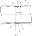
- Figure 1 illustrates a cross-sectional view of a drill arrangement according to an aspect of the description.
- a casing pipe 1, particularly a first end portion 2 thereof is shown as connected to a second end portion 3 of another similar casing pipe 1.
- the outer surface of the first end portion 2 is effectively tapered such that it narrows towards said first end.
- the inner surface of the second end portion 3 is effectively tapered such that it expands towards said second end.
- the phrasing effectively tapered means that the general dimension increases or decreases towards an end.
- an effectively tapered end portion may comprise sections at which the dimension locally remains constant or even increases.
- the first end portion 2 comprises an outermost groove element 2a, an intermediate groove element 2b, and an innermost groove element 2c.
- the second end portion 3 comprises an outermost shoulder element 3c, an intermediate shoulder element 3b, and an innermost shoulder element 3a.
- the outermost groove element 2a or shoulder element 3c is an element being closest to its respective end, and respectively, an innermost groove element 2c or shoulder element 3a is an element being furthest from its respective end.
- the outermost groove element 2a of the first end portion is arranged as complementary with the innermost shoulder element 3c of the second end portion 3 so as to form interlocking shapes with each other.
- the innermost groove element 2c of the first end portion is arranged as complementary with the outermost shoulder element 3c of the second end portion 3 so as to form interlocking shapes with each other.
- the intermediate groove element 2c of the first end portion is arranged as complementary with the intermediate shoulder element 3c of the second end portion 3 so as to form interlocking shapes with each other.
- each respective groove element and its respective shoulder element complementary with each other has their own specific effective dimension, That is, in the case of Fig. 1 , the inner diameter of the outermost groove element 2a on the first end portion 2 shares its effective dimension with the innermost shoulder element 3c of the second end portion, namely both the outer diameter of the outermost groove element 2a and the inner diameter of the innermost shoulder element 3c have an effective dimension of Da.
- the outer diameter of the innermost groove element 2c and the inner diameter of the outermost shoulder element 3a have a shared effective dimension of Dc.
- the outer diameter of the intermediate groove element 2b and the inner diameter of the intermediate shoulder element 3b have a shared effective dimension of Db.
- the effective dimensions Da, Db, Dc on the first end portion are arranged to decrease towards the respective end of the first end portion 2.
- the effective dimensions Dc, Db, Da on the second end portion are arranged to increase towards the respective end of the second end portion 3.
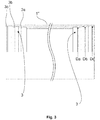
- Fig. 2 illustrates an alternative embodiment according to an aspect of the description.
- a casing pipe 1' has a first end portion 2 equipped with first attachment means at both of its ends.
- Fig. 3 illustrates an alternative embodiment according to an aspect of the description.
- a casing pipe 1" has a second end portion 3 equipped with second attachment means at both of its ends.
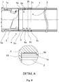
- Fig. 4 illustrates a casing pipe assembly comprising casing shoe 4 coupling a drill tool 7 with a casing pipe 1.
- the casing shoe 4 has a tubular casing extending between a tool end portion 5 and a pipe end portion 6.
- the pipe end portion 6 is equipped with attachment means substantially corresponding to the second attachment means of Fig. 1 and Fig. 3 . Particularly, an innermost shoulder element 6a, an intermediate shoulder element 6b, and an outermost shoulder element 6c are provided on the inner surface of the casing on the pipe end portion 6.
- the pipe end portion 6 is further equipped with an abutting surface 6d for abutting the end of the casing pipe 1.
- the abutting surface 6d is provided as an annular surface on the inside of the casing. As can be seen more clearly from Detail A of Fig. 4 the abutting surface 6d is slightly inclined from a vertical to the longitudinal axis of the arrangement. Particularly, the abutting surface 6d is inclined towards the pipe end portion 6 in direction in an inward direction.
- the pipe end portion 6 and the tool end portion 5 are connected to each other in a radially and axially fixed manner, while permitting rotational movement therebetween.
- the coupling between the pipe end portion 6 and the tool end portion 5 is provided with an annular groove 6e on the outside of the pipe end portion, and correspondingly with an annular shoulder 5b on the inside of the tool end portion 5.
- the tool end portion 5 of the casing shoe 4 is connected to a drill tool 7, particularly a ring bit, in a radially and axially fixed manner while permitting rotational movement therebetween.
- the coupling between the tool 7 and the tool end portion 5 is provided with an annular shoulder 5a on the inside of the tool end portion 5, and correspondingly, an annular groove 7a on the outer circumference of the drill tool 7.
- Fig. 5 illustrates the casing pipe arrangement of Fig. 4 further equipped with damping means 8.
- the purpose of the damping means is to dampen drilling impact forces carried on to the casing pipe 1 by the casing shoe 4.
- a percussive force may be exerted on to the drill tool 7 for penetrating the ground material.
- the groove 7a on the drill tool 7 and the shoulder 5a on the tool end portion 5 of casing shoe 4, are arranged to provide an axial motion clearance for enabling the percussive motion of the drill tool, while allowing the drill tool 7 to pull the casing pipe 1 via the casing shoe 4.
- the casing pipe 1 may drag behind in the drill hole. That is, a substantial force is needed to advance the casing pipe 1.
- Fig. 5 is equipped with a damping means 8 for alleviating the harshness of the impacts.
- a damping means 8 is provided as an annular element of elastic material between the surfaces of the groove 7a on the drill tool
- a further damping means 8 may be provided between the tool end portion 5 and the pipe end portion 6 of the casing shoe, i.e. as an annular element of elastic material between the surfaces of the groove 6e on the pipe end portion end portion 6 and the shoulder 5b on the tool end portion 5 of the casing shoe 4, that abut each other when the drill tool 7 is pushed further by the percussive drilling forces.
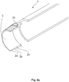
- Fig. 6A and Fig. 6B illustrate a casing pipe 1 and an end portion 2 thereof being provided before and after being attached to each other, respectively.
- the first end portion 2 is equipped with attachment means 2a, 2b, 2c being provided as grooves, and 2d being provided as a lug.
- Fig. 7 illustrates a drill arrangement in which a casing pipe 1 has not yet been attached to a drill bit 7 equipped with a casing shoe 4.
- the casing shoe 4 has been attached to the drill bit, in this case a ring bit 7.
- the casing shoe 4 provided as two-part form, the portions of which 5 6 being rotationally disengaged with each other allowing rotational movement therebetween.
- the casing pipe 1 side portion of the casing shoe 4 is equipped with pockets 4a.
- the first end portion 2 has attachment means 2a, 2b, 2c being provided as grooves, and 2d being provided as a lug.
- the attachment means 2a, 2b, 2c are to be receivable within the casing pipe 1 side portion 6 of the casing shoe 4 for radially and axially fixing the casing pipe 1 to the casing shoe 4.
- the lug 2d is to be receivable within the pocket 4a for locking the casing pipe 1 to the casing shoe 4 in a rotational manner.
- a casing pipe 1 for drilling is provided.
- the casing pipe 1 has a tubular casing extending between a first end portion 2 and a second end portion 3 thereof.
- the first end portion 2 is equipped first attachment means 2a, 2b, 2c, and respectively, the second end portion 3 is equipped with second attachment means 3a, 3b, 3c, for attaching casing pipes 1 one after another.
- the first attachment means comprises, on an outer surface of the casing, an outermost groove element 2a and an innermost groove element 2c.
- the second attachment means comprises, on an inner surface of the casing, an innermost shoulder element 3a and an outermost shoulder element 3c.
- the outermost groove element 2a of the first attachment means is arranged to co-operate with the innermost shoulder 3a element of the second attachment means, so as to form interlocking shapes with each other for attaching consecutive casing pipes to each other.
- the innermost groove element 2c of the first attachment means is arranged to co-operate with the outermost shoulder 3c element of the second attachment means, so as to form interlocking shapes with each other for attaching consecutive casing pipes to each other.
- first attachment means could naturally be implemented with shoulder elements instead of groove elements, in which case the second attachment means would be implemented with groove elements instead of shoulder elements.
- At least the first attachment means, the second attachment means, or both have a structural elasticity enabling temporary deformation permitting the shoulder elements 3a, 3b, 3c to be inserted into the respective groove 2a, 2b, 2c elements.
- Such structural elasticity may be provided, for example, by manufacturing the first, second, or both, attachment means from a suitable material, such as a plastics material.
- the whole casing pipe 1 is made of the same material.
- An alternative way of producing such structural elasticity is providing one or more axial slits extending through the casing, thus providing an intermittent circumference at the location of first, second, or both,
- effective dimensions Da, Db, Dc of the groove elements 2a, 2b, 2c on the first end portion 2 decreases towards its respective end
- effective dimensions Da, Db, Dc of the shoulder elements 3a, 3b, 3c on the second end portion 3 increase towards its respective end
- At least one, preferably both of the first end portion 2 and second end portion 3 are attached to the tubular casing of the casing pipe 1 by friction welding, most preferably by spin welding. That is, at least one, preferably both end portions 2, 3 are formed separately, and subsequently attached to the rest of the casing pipe. Preferably, either or both of the end portions 2, 3 are formed from a portion of a pipe having a larger material thickness than that of the rest of the tubular casing of the casing pipe 1.
- an alternative casing pipe 1' is provided.
- the casing pipe 1' according to the second aspect differs from the casing pipe 1 according to the first aspect by two identical first end portions 2, each provided with first attachment means.
- a casing pipe 1' according to the second aspect has a tubular casing extending between two identical first end portions 2.
- Both of the first end portions 2 are each equipped with a first attachment means for attaching the casing pipe with a second attachment means.
- the second attachment means may be a part of another casing pipe 1, 1" or a casing shoe 4, for example.
- the first attachment means comprises, on an outer surface of the casing, at least an outermost complimentary groove element 2a and an innermost complimentary groove element 2c.
- the second attachment means referred to comprises, on an inner surface of a casing, at least an innermost complimentary shoulder element 3a, 6a and an outermost complimentary shoulder element 3c, 6c.
- the outermost groove element 2a of the first attachment means is arranged to co-operate with said innermost shoulder 3a, 6a element of the second attachment means, so as to form interlocking shapes with each other, suitably for attaching consecutive casing pipes to each other, and respectively,
- the innermost groove element 2c of the first attachment means is arranged to co-operate with said outermost shoulder 3c, 6c element of the second attachment means, so as to form interlocking shapes with each other, suitably for attaching consecutive casing pipes to each other;
- At least the first attachment means, at least the second attachment means, or both have a structural elasticity enabling temporary deformation permitting the shoulder elements to be inserted into the respective groove elements
- first attachment means could naturally be implemented with shoulder elements instead of groove elements, in which case the second attachment means would be implemented with groove elements instead of shoulder elements.
- first end portions 2 are attached to the tubular casing of the casing pipe 1' by friction welding, most preferably by spin welding. That is, at least one, preferably both first portions 2, are formed separately, and subsequently attached to the rest of the casing pipe 1'. Preferably, either or both of the end portions 2 are formed from a portion of a pipe having a larger material thickness than that of the rest of the tubular casing of the casing pipe 1.
- an alternative casing pipe 1" is provided.
- the casing pipe 1" according to the third aspect differs from the casing pipe 1 according to the first aspect by having two identical second end portions 3, both provided second attachment means.
- a casing pipe 1" has a tubular casing extending between two identical second end portions 3, wherein both of the second end portions 3 are each equipped with a second attachment means for attaching such casing pipes to a first attachment means.
- the second attachment means may be a part of another casing pipe 1,1' or a casing shoe, for example.
- the first attachment means referred to comprises, on an outer surface of a casing, at least an outermost complimentary groove element 2a and an innermost complimentary groove element 2c.
- the second attachment means comprises, on an inner surface of the casing, at least an innermost complimentary shoulder 3a element and an outermost complimentary shoulder 3c element.
- the innermost shoulder element 3a of the second attachment means is arranged to co-operate with an outermost groove element 2a of the first attachment means, so as to form interlocking shapes with each other, suitably for attaching consecutive casing pipes to each other.
- said outermost shoulder element 3c of the second attachment means is arranged to co-operate with an innermost groove element 2c of the first attachment means, so as to form interlocking shapes with each other, suitably for attaching consecutive casing pipes to each other.
- At least the first attachment means, at least the second attachment means, or both have a structural elasticity enabling temporary deformation permitting the shoulder elements to be inserted into the respective groove elements.
- Either, or preferably both second end portions 3 are attached to the tubular casing of the casing pipe 1" by friction welding, most preferably by spin welding. That is, at least one, preferably both first portions 3, are formed separately, and subsequently attached to the rest of the casing pipe 1". Preferably, either or both of the end portions 3 are formed from a portion of a pipe having a larger material thickness than that of the rest of the tubular casing of the casing pipe 1".
- the casing pipes 1', 1" according to the second and third aspects may be connected to each other in a casing string, which may be formed by using casing pipes according to the second and third aspect alternately.
- the first attachment means further comprises, on an outer surface of its casing, at least an axially extending lug 2d or pocket.
- the second attachment means further comprises, on an inner surface of its casing, an axially extending pocket or lug.
- the lug and pocket being arranged to co-operate with each other such as to form interlocking shapes for preventing consecutive casing pipes 1, 1', 1" from rotating about their longitudinal axis with respect to each other. That is, when consecutive casing pipes 1, 1', 1" having such a lug and pocket construction are attached to each other, the lug 2d is received in the pocket, thus preventing the consecutive casing pipes from being rotated about their longitudinal axis with respect to each other. Consequently, the respective attachment means are prevented from rotating with respect to each other. This also contributes to providing a more reliable connection between the casing pipes, as any possible rotation between the respective attachment means may damage the shoulder and groove elements. This advantage is particularly prominent where plastic casing pipes are used, as plastic is more easily damaged.
- the first attachment means further comprise at least one intermediate groove element 2b
- the second attachment means further comprise at least one intermediate shoulder element 3c.
- the at least one intermediate groove element 2b of the first attachment means is arranged to co-operate with the at least one intermediate shoulder element 3c of the second attachment means, so as to form interlocking shapes with each other for attaching consecutive casing pipes to each other.
- first attachment means may be implemented with shoulder elements, in which case the second attachment means should be implemented with groove elements.
- At least one of the shoulder elements 3a, 3b, 3c is an annular ring radially protruding from, and tangentially extending around the circumference of the outer surface of the casing.
- Respectively at least one of the groove elements 2a, 2b, 2c is an annular recess radially protruding into, and tangentially extending around the circumference of the inner surface of the casing.
- the shoulder elements and groove elements are preferably mutually of the same type, their dimensioning may vary between each other. For example, some of the corresponding groove elements and shoulder elements may have a different width or height with respect to the other groove elements and shoulder elements.
- the casing pipe 1, 1', 1" is made of a plastics material.
- Plastic materials are generally light compared to conventional materials form which casing pipes are manufactured. Moreover, most plastics naturally provide a suitable structural elasticity, i.e. capability to temporarily deform.
- thermoplastics such as polyolefins, particularly polyethylene and polypropylene have been discovered to be suitable plastics for producing a casing pipe according to the description.
- a casing pipe 1, 1', 1" may be formed from a PE100 pipe material.
- the first end portion 2, the second end portion 3, or both have an increased casing material thickness with respect to the rest of the casing pipe 1, 1', 1".
- Increasing the material thickness of either end portion 2, 3 increases the strength of the coupling formed by the attachment means.
- this enables groove elements 2a, 2b, 2c and / or shoulder elements 3a, 3b, 3c to be formed even into a casing having a material thickness between the end portions too thin for forming such forms. This contributes to material costs savings and overall weight reduction, as the thickness of the casing between the end portions, constituting most of the weight of the casing pipe, can be reduced.
- the material thickness of either end portion 2, 3 may be increased in several different ways. Most suitably, the material thickness may be increased by providing an upset.
- a sleeve or a bushing may be provided
- a casing pipe 1, 1', 1" is equipped with an abutting surface provided at the first attachment means, the second attachments means, or both.
- the abutting surface is to prevent the first and second attachment means from being pushed past each other by acting as a stopper.
- the abutting surface is inclined, suitably so as to guide any possible deformation of a casing pipe, being coupled with another casing pipe, towards the casing of the other casing pipe.
- the abutting surface may guide any possible deformation to a direction in which the casing of the other casing pipe will provide additional support for the casing pipe. That is, preferably the abutting surface is inclined so as to prevent either of, or both, successive casing pipes from deforming away from each
- the abutting surface is preferably arranged as an annular surface on the outside of the casing of a casing pipe 1, 1', preferably inclined towards its respective end a direction outward from the casing.
- the abutting surface 6d is preferably arranged as an annular surface on the inside of the casing of a casing pipe 1, 1", preferably inclined towards its respective end in a direction inward from the casing.
- a casing pipe arrangement comprises two or more of the casing pipes 1, 1', 1'" according to any of the aspects discussed above.
- the casing pipes 1, 1', 1" are attached one after another such that first attachment means of a subsequent casing pipe is inserted into second attachment means of a preceding casing pipe.
- a casing shoe 4 is provided.
- the casing shoe 4 is provided with attachment means corresponding to either the first attachment means or second attachment means of a casing pipe 1, 1', 1" according to any of the aspects discussed above.
- a casing shoe 4 has a tubular casing extending between a tool end portion 5 and a pipe end portion 6.
- the tool end portion 5 is preferably arranged for being coupled with a drilling tool, whereas the pipe end portion is arranged for being coupled with a casing pipe.
- the casing shoe 4 is equipped at least one axially extending lug or pocket 4a arranged to correspond with a pocket or lug 2d of a casing pipe 1, 1', 1", respectively. That is, the lug or pocket being arranged to co-operate with a pocket or lug of casing pipe 1, 1', 1" such as to form interlocking shapes for preventing consecutive casing pipes 1, 1', 1" from rotating about its longitudinal axis with respect to the casing shoe 4, particularly the portion of which the casing pipe 1, 1', 1" is connected to.
- the pipe end portion 6 may be equipped with first attachment means, for attaching the casing shoe 4 to a second attachment means of a casing pipe 1, 1".
- the first attachment means comprise, on an outer surface of the casing, at least an outermost complimentary shoulder element or groove element and an innermost complimentary shoulder element or groove element.
- the pipe end portion 6 is equipped with second attachment means for attaching the casing shoe 4 to a first attachment means of a casing pipe 1, 1'.
- the second attachment means comprise, on an inner surface of the casing, at least an innermost complimentary groove element or shoulder 6a element and an outermost complimentary groove element or shoulder 6c element,
- the outermost shoulder element or groove element of said first attachment means is arranged to co-operate with an innermost groove element or shoulder 3a element of a second attachment means on a casing pipe 1, 1", so as to form interlocking shapes with each other.
- the innermost shoulder element or groove element of said he first attachment means would correspondingly be arranged to co-operate with an outermost groove element or shoulder 3c element of the second attachment means, so as to form interlocking shapes with each other.
- the outermost shoulder element 6c or groove element of said second attachment means is arranged to co-operate with an innermost groove element 2c or shoulder element of a first attachment means on a casing pipe 1, 1', so as to form interlocking shapes with each other.
- the innermost shoulder element 6a or groove element of the second attachment means would correspondingly be arranged to co-operate with said outermost groove element 2a or shoulder element of the first attachment means on a casing pipe 1, 1', so as to form interlocking shapes with each other.
- At least the first attachment means, at least the second attachment means, or both have a structural elasticity enabling temporary deformation permitting the shoulder elements to be inserted into the respective groove elements.
- the pipe end portion 6, having either first or second attachment means may additionally be provided with an intermediate shoulder element 6b, or groove element, corresponding to that of the respective attachment means of a casing pipe 1, 1', 1" to be joined.
- the effective dimensions Da, Db, Dc of the groove elements or the shoulder elements on the first attachment means on the casing shoe decrease towards the pipe end portion side.
- the effective dimensions Da, Db, Dc of the groove elements or the shoulder elements on the second attachment means on the casing shoe 4 increase towards the pipe end portion 6 side end.
- the casing shoe 4 as discussed in connection with the preceding aspect is further arranged to provide a rotational decoupling.
- the tool end portion 5 is axially and radially connectable to a drill tool 7 allowing rotational movement therebetween.
- this is provided by arranging a complementary shoulder element 5a and a groove element 7a on the tool end portion 5 of the casing shoe and on the drill tool 7, respectively.
- the groove and shoulder elements may arranged the other way round.
- the pipe end portion 6 is axially and radially connectable to the tool end portion 5 allowing rotational movement therebetween, Suitably, this is provided by arranging a complementary shoulder element 5b and a groove element 6e on the tool end portion 5 of the casing shoe and on the pipe end portion of the casing shoe 4, respectively.
- the groove and shoulder elements may arranged the other way round.
- Such a casing shoe 4 enables a casing pipe 1, 1', 1" to be coupled with drill tool axially and radially, while being rotationally disconnected from the drill tool at least between the pipe end portion 6 and the tool end portion 5 of the casing shoe 4, and respectively, between tool end portion 5 of the casing shoe 4 and the drill tool 7.
- connection between subsequent casing pipes 1 do not generally tolerate rotation as well as conventional welded joints.
- This is particularly prominent when the first attachment means, the second attachment means, or both are made from a plastic material.
- conventional casing shoes are rotationally disconnect from the drill tool at only one point, namely the outer periphery of the drill tool. Should this rotational joint get clogged, a part of the torsional moment of the drill tool 7 is transferred onwards to the casing shoe 4.
- the casing shoe 4 preferably made of metal, such as steel, will in turn transfer a part of the torsional moment to the casing pipe 1, 1', 1", which will eventually become damaged, at least if made of a plastics material.
- the casing pipe discussed in the above aspect provides a casing shoe disconnecting the casing pipe from the drill tool at two separate location, enabling thus a more reliable joint to be formed.
- the casing shoe 4 as discussed in connection with any of the preceding aspect is further equipped with an abutting surface 6d.
- the purpose of the abutting surface 6d is to prevent the first and second attachment means from being pushed past each other by acting as a stopper.
- the abutting surface 6d is inclined so as to guide any possible deformation of a casing pipe 1, 1', 1" being coupled with the casing shoe 4 towards the casing of the casing shoe.
- the abutting surface may guide any possible deformation to a direction in which the casing of the casing shoe will provide additional support for the casing pipe. That is, preferably the abutting surface 6d is inclined so as to prevent the casing pipe 1, 1', 1", pipe end portion 6, or both, from deforming away from each other.
- the abutting surface 6d is preferably arranged as an annular surface on the outside of the casing, preferably inclined towards the pipe end portion 6 side end, in a direction outward from the casing.
- the abutting surface 6d is preferably arranged as an annular surface on the inside of the casing, preferably inclined towards the pipe end portion 6 side end, in a direction inward from the casing.
- a casing shoe 4 according to any of the preceding casing shoe aspects, as discussed above, is provided with an intermediate portion.
- the purpose of the intermediate portion is to provide a rotational decoupling between the tool end portion 5 and the pipe end portion 6 of the casing shoe. If the tool end portion 5 and the pipe end portion 6 of the casing shoe are already rotationally decoupled with respect to each other, an intermediate portion may be provided for enabling further rotational decoupling between the tool end portion 5 and the pipe end portion 6.
- the casing shoe 4 may be provided with more than one intermediate portions for providing further rotational decoupling.
- the tool end portion 5 and the pipe end portion 6 may be connected to each other via on or more intermediate portion axially and radially connectable between the tool end portion 5 and the pipe end portion 5, between the tool end portion 5 and another intermediate portion, between the pipe end portion and another intermediate portion, between two other intermediate portions, or any combination thereof.
- a tool arrangement comprises a casing shoe 4 as discussed in connection with any of the preceding aspects.
- the tool end portion 5 of the casing shoe 4 is attached to drill tool 7 in an axially and radially fixed manner, while allowing rotational movement between the drill tool 7 and the tool end portion 5.
- the drill tool 7 is a ring bit.
- the tool arrangement is equipped with a damping means 8 for damping impact forces from the drill tool 7 transmitted to the casing pipe 1, 1', 1" via the casing shoe 4.
- the damping means 8 are arranged between the complimentary shoulder element 5a on the tool end portion 5 of the casing shoe 4 and the respective groove element 7a on the drill tool.
- a further damping means 8 may be arranged between the complementary shoulder element 5b on the tool end portion 5 of the casing shoe 4 and respective the groove element 6e on the pipe end portion 6 of the casing shoe 4.
- damping means 8 may be arranged in corresponding manner should the groove elements and shoulder elements be arranged other way round.
- the damping means are preferably arranged between surface of the respective groove and shoulder elements that abut each other when the drill tool 7 is pushed further by the percussive drilling forces.
- annular damping means 8 of elastic material are used, such as O-rings made from an elastomer material
- a drill arrangement comprises at least one casing pipe according to any of the casing pipe aspects discussed above.
- the drill arrangement comprises a drill tool 7 attached to the casing pipe, preferably via a casing shoe, in an axially and radially fixed manner, while allowing rotational movement between the drill tool 7 and the casing pipe.
- the drill tool 7 is a ring bit.
- the drill arrangement comprises casing pipe 1, 1', 1" according to any of the casing pipe aspects discussed above and a casing shoe according to any of the casing shoe aspects discussed above.
- the casing pipe 1, 1', 1" is attached to the pipe end portion of the casing shoe 4.
- the drill arrangement may additionally comprise a drill tool 7, in which case the drill tool is preferably attached to the tool end portion 5 of the casing shoe in an axially and radially fixed manner, while allowing rotational movement between the drill tool 7 and the tool end portion 5.
- the drill tool 7 is a ring bit.
Landscapes
- Engineering & Computer Science (AREA)
- Life Sciences & Earth Sciences (AREA)
- Geology (AREA)
- Mining & Mineral Resources (AREA)
- Mechanical Engineering (AREA)
- Physics & Mathematics (AREA)
- Environmental & Geological Engineering (AREA)
- Fluid Mechanics (AREA)
- General Life Sciences & Earth Sciences (AREA)
- Geochemistry & Mineralogy (AREA)
- Earth Drilling (AREA)
Applications Claiming Priority (1)
| Application Number | Priority Date | Filing Date | Title |
|---|---|---|---|
| FI20156016 | 2015-12-29 |
Publications (1)
| Publication Number | Publication Date |
|---|---|
| EP3203009A1 true EP3203009A1 (de) | 2017-08-09 |
Family
ID=57590393
Family Applications (1)
| Application Number | Title | Priority Date | Filing Date |
|---|---|---|---|
| EP16206335.8A Withdrawn EP3203009A1 (de) | 2015-12-29 | 2016-12-22 | Bohrrohr, bohrrohranordnung,bohrrohrschuh, werkzeuganordnung mit einem bohrrohrschuh und bohranordnung |
Country Status (1)
| Country | Link |
|---|---|
| EP (1) | EP3203009A1 (de) |
Cited By (5)
| Publication number | Priority date | Publication date | Assignee | Title |
|---|---|---|---|---|
| CN109426749A (zh) * | 2017-08-28 | 2019-03-05 | 广州本安信息科技有限公司 | 雷管定位扫描组件 |
| CN109426752A (zh) * | 2017-08-28 | 2019-03-05 | 广州本安信息科技有限公司 | 雷管定位扫描装置 |
| CN109426754A (zh) * | 2017-08-28 | 2019-03-05 | 广州本安信息科技有限公司 | 雷管定位扫描机构 |
| CN109426751A (zh) * | 2017-08-28 | 2019-03-05 | 广州本安信息科技有限公司 | 雷管定位扫描固定机构 |
| CN109426748A (zh) * | 2017-08-28 | 2019-03-05 | 广州本安信息科技有限公司 | 雷管定位扫描固定装置 |
Citations (5)
| Publication number | Priority date | Publication date | Assignee | Title |
|---|---|---|---|---|
| GB1421530A (en) * | 1971-10-14 | 1976-01-21 | Pryor T G | Pipe or tube coupling |
| US4298221A (en) * | 1977-01-26 | 1981-11-03 | Hunting Oilfield Services (U.K.) Limited | Pipe connectors |
| US4779902A (en) | 1987-07-06 | 1988-10-25 | Mid-Continent Pipe & Supply Co., Inc. | Plastic pipe with integral end connection |
| WO1999043974A1 (en) * | 1998-02-25 | 1999-09-02 | Grant Prideco, Inc. | Threaded connection for internally clad pipe |
| US20100308577A1 (en) * | 2009-06-04 | 2010-12-09 | National Oilwell Varco, L.P. | drill pipe system and method for using same |
-
2016
- 2016-12-22 EP EP16206335.8A patent/EP3203009A1/de not_active Withdrawn
Patent Citations (5)
| Publication number | Priority date | Publication date | Assignee | Title |
|---|---|---|---|---|
| GB1421530A (en) * | 1971-10-14 | 1976-01-21 | Pryor T G | Pipe or tube coupling |
| US4298221A (en) * | 1977-01-26 | 1981-11-03 | Hunting Oilfield Services (U.K.) Limited | Pipe connectors |
| US4779902A (en) | 1987-07-06 | 1988-10-25 | Mid-Continent Pipe & Supply Co., Inc. | Plastic pipe with integral end connection |
| WO1999043974A1 (en) * | 1998-02-25 | 1999-09-02 | Grant Prideco, Inc. | Threaded connection for internally clad pipe |
| US20100308577A1 (en) * | 2009-06-04 | 2010-12-09 | National Oilwell Varco, L.P. | drill pipe system and method for using same |
Cited By (6)
| Publication number | Priority date | Publication date | Assignee | Title |
|---|---|---|---|---|
| CN109426749A (zh) * | 2017-08-28 | 2019-03-05 | 广州本安信息科技有限公司 | 雷管定位扫描组件 |
| CN109426752A (zh) * | 2017-08-28 | 2019-03-05 | 广州本安信息科技有限公司 | 雷管定位扫描装置 |
| CN109426754A (zh) * | 2017-08-28 | 2019-03-05 | 广州本安信息科技有限公司 | 雷管定位扫描机构 |
| CN109426751A (zh) * | 2017-08-28 | 2019-03-05 | 广州本安信息科技有限公司 | 雷管定位扫描固定机构 |
| CN109426748A (zh) * | 2017-08-28 | 2019-03-05 | 广州本安信息科技有限公司 | 雷管定位扫描固定装置 |
| CN109426752B (zh) * | 2017-08-28 | 2024-07-02 | 广州本安信息科技有限公司 | 雷管定位扫描装置 |
Similar Documents
| Publication | Publication Date | Title |
|---|---|---|
| EP3203009A1 (de) | Bohrrohr, bohrrohranordnung,bohrrohrschuh, werkzeuganordnung mit einem bohrrohrschuh und bohranordnung | |
| US9038751B2 (en) | Down-hole hammer drill | |
| US6902205B2 (en) | Coupling for composite pipe | |
| AU2015217773B2 (en) | Drill string component coupling device | |
| JP2001524196A (ja) | 超高トルクダブルショルダー型工具継手 | |
| CN103392052A (zh) | 抗卡住的钻柱部件 | |
| CN102171502B (zh) | 用于钻探和操作烃井的部件 | |
| RU2714405C2 (ru) | Резьбовой соединительный конец для компонента бурильной колонны | |
| EA034062B1 (ru) | Уравновешенная форма резьбы и трубные изделия с такой резьбой | |
| JP5633995B2 (ja) | 内部補強リングを備えるドリルステムの管接続 | |
| EP1337735B1 (de) | Schraubgelenk zum schlagbohren und teile dafür | |
| WO2018143819A1 (en) | A coupling | |
| US3447340A (en) | Resilient unit for drill strings | |
| US6712402B2 (en) | Double shoulder oilfield tubular connection | |
| CN210067990U (zh) | 石油钻杆 | |
| CN207160975U (zh) | 一种超短半径造斜钻具的长度补偿钻杆装置 | |
| BR112020021026A2 (pt) | Conexão tubular rosqueada para envoltório | |
| JP2017512291A (ja) | 荷重偏向領域を備えた管カップリング | |
| CN113454310B (zh) | 钻柱杆 | |
| JP3202755U (ja) | 伝動軸の構造 | |
| US11015399B2 (en) | Coupling assembly for elongate elements | |
| CN114364860A (zh) | 肩部受保护的钻凿组件 | |
| EP3577303B1 (de) | Kupplung | |
| EP3822449B1 (de) | Kupplung | |
| EP3875822A1 (de) | Koppler zum verbinden mit einem rohr und verfahren zur herstellung des kopplers |
Legal Events
| Date | Code | Title | Description |
|---|---|---|---|
| PUAI | Public reference made under article 153(3) epc to a published international application that has entered the european phase |
Free format text: ORIGINAL CODE: 0009012 |
|
| STAA | Information on the status of an ep patent application or granted ep patent |
Free format text: STATUS: THE APPLICATION HAS BEEN PUBLISHED |
|
| AK | Designated contracting states |
Kind code of ref document: A1 Designated state(s): AL AT BE BG CH CY CZ DE DK EE ES FI FR GB GR HR HU IE IS IT LI LT LU LV MC MK MT NL NO PL PT RO RS SE SI SK SM TR |
|
| AX | Request for extension of the european patent |
Extension state: BA ME |
|
| STAA | Information on the status of an ep patent application or granted ep patent |
Free format text: STATUS: REQUEST FOR EXAMINATION WAS MADE |
|
| 17P | Request for examination filed |
Effective date: 20171128 |
|
| RBV | Designated contracting states (corrected) |
Designated state(s): AL AT BE BG CH CY CZ DE DK EE ES FI FR GB GR HR HU IE IS IT LI LT LU LV MC MK MT NL NO PL PT RO RS SE SI SK SM TR |
|
| STAA | Information on the status of an ep patent application or granted ep patent |
Free format text: STATUS: EXAMINATION IS IN PROGRESS |
|
| STAA | Information on the status of an ep patent application or granted ep patent |
Free format text: STATUS: EXAMINATION IS IN PROGRESS |
|
| 17Q | First examination report despatched |
Effective date: 20200529 |
|
| STAA | Information on the status of an ep patent application or granted ep patent |
Free format text: STATUS: THE APPLICATION IS DEEMED TO BE WITHDRAWN |
|
| 18D | Application deemed to be withdrawn |
Effective date: 20201009 |