EP3202939B1 - Austenitic heat-resistant cast steel having excellent thermal fatigue characteristics, and exhaust system component comprising same - Google Patents
Austenitic heat-resistant cast steel having excellent thermal fatigue characteristics, and exhaust system component comprising same Download PDFInfo
- Publication number
- EP3202939B1 EP3202939B1 EP15846497.4A EP15846497A EP3202939B1 EP 3202939 B1 EP3202939 B1 EP 3202939B1 EP 15846497 A EP15846497 A EP 15846497A EP 3202939 B1 EP3202939 B1 EP 3202939B1
- Authority
- EP
- European Patent Office
- Prior art keywords
- heat
- com
- resistant
- cast steel
- thermal fatigue
- Prior art date
- Legal status (The legal status is an assumption and is not a legal conclusion. Google has not performed a legal analysis and makes no representation as to the accuracy of the status listed.)
- Active
Links
- 229910001208 Crucible steel Inorganic materials 0.000 title claims description 84
- 239000002245 particle Substances 0.000 claims description 32
- 150000004767 nitrides Chemical class 0.000 claims description 23
- 239000012535 impurity Substances 0.000 claims description 10
- 239000003054 catalyst Substances 0.000 claims description 7
- 238000000034 method Methods 0.000 claims description 3
- 239000011651 chromium Substances 0.000 description 59
- 239000010955 niobium Substances 0.000 description 49
- 230000003647 oxidation Effects 0.000 description 38
- 238000007254 oxidation reaction Methods 0.000 description 38
- PXHVJJICTQNCMI-UHFFFAOYSA-N nickel Substances [Ni] PXHVJJICTQNCMI-UHFFFAOYSA-N 0.000 description 33
- 230000000052 comparative effect Effects 0.000 description 30
- 238000012360 testing method Methods 0.000 description 29
- 239000007789 gas Substances 0.000 description 28
- 238000001816 cooling Methods 0.000 description 27
- 238000010438 heat treatment Methods 0.000 description 27
- 229910000831 Steel Inorganic materials 0.000 description 25
- 239000010959 steel Substances 0.000 description 25
- 239000011159 matrix material Substances 0.000 description 24
- 239000011572 manganese Substances 0.000 description 20
- 208000016261 weight loss Diseases 0.000 description 15
- 229910001566 austenite Inorganic materials 0.000 description 14
- 230000006835 compression Effects 0.000 description 14
- 238000007906 compression Methods 0.000 description 14
- 239000013585 weight reducing agent Substances 0.000 description 14
- 239000000463 material Substances 0.000 description 13
- 239000000203 mixture Substances 0.000 description 13
- 239000006104 solid solution Substances 0.000 description 13
- 229910052799 carbon Inorganic materials 0.000 description 11
- 230000000694 effects Effects 0.000 description 11
- 238000005266 casting Methods 0.000 description 10
- 229910052804 chromium Inorganic materials 0.000 description 10
- 238000005336 cracking Methods 0.000 description 9
- 238000009661 fatigue test Methods 0.000 description 9
- 239000000446 fuel Substances 0.000 description 9
- 239000013078 crystal Substances 0.000 description 8
- 230000001747 exhibiting effect Effects 0.000 description 8
- 238000004140 cleaning Methods 0.000 description 7
- 229910052757 nitrogen Inorganic materials 0.000 description 7
- 238000002425 crystallisation Methods 0.000 description 6
- 230000008025 crystallization Effects 0.000 description 6
- 150000001247 metal acetylides Chemical class 0.000 description 6
- 229910052750 molybdenum Inorganic materials 0.000 description 6
- 229910052758 niobium Inorganic materials 0.000 description 6
- 150000004763 sulfides Chemical class 0.000 description 6
- 229910052721 tungsten Inorganic materials 0.000 description 6
- -1 MnS Chemical class 0.000 description 5
- 230000005496 eutectics Effects 0.000 description 5
- 229910052759 nickel Inorganic materials 0.000 description 5
- 230000001590 oxidative effect Effects 0.000 description 5
- 239000000126 substance Substances 0.000 description 5
- MCMNRKCIXSYSNV-UHFFFAOYSA-N Zirconium dioxide Chemical compound O=[Zr]=O MCMNRKCIXSYSNV-UHFFFAOYSA-N 0.000 description 4
- 238000005516 engineering process Methods 0.000 description 4
- 235000000396 iron Nutrition 0.000 description 4
- MWUXSHHQAYIFBG-UHFFFAOYSA-N Nitric oxide Chemical compound O=[N] MWUXSHHQAYIFBG-UHFFFAOYSA-N 0.000 description 3
- 230000008859 change Effects 0.000 description 3
- 230000002542 deteriorative effect Effects 0.000 description 3
- 229910052748 manganese Inorganic materials 0.000 description 3
- 238000005259 measurement Methods 0.000 description 3
- 239000000155 melt Substances 0.000 description 3
- 230000009467 reduction Effects 0.000 description 3
- 229910052710 silicon Inorganic materials 0.000 description 3
- 238000007711 solidification Methods 0.000 description 3
- 230000008023 solidification Effects 0.000 description 3
- 230000035882 stress Effects 0.000 description 3
- 229910052717 sulfur Inorganic materials 0.000 description 3
- IJGRMHOSHXDMSA-UHFFFAOYSA-N Atomic nitrogen Chemical compound N#N IJGRMHOSHXDMSA-UHFFFAOYSA-N 0.000 description 2
- OKTJSMMVPCPJKN-UHFFFAOYSA-N Carbon Chemical compound [C] OKTJSMMVPCPJKN-UHFFFAOYSA-N 0.000 description 2
- UCKMPCXJQFINFW-UHFFFAOYSA-N Sulphide Chemical compound [S-2] UCKMPCXJQFINFW-UHFFFAOYSA-N 0.000 description 2
- 230000004913 activation Effects 0.000 description 2
- 229910045601 alloy Inorganic materials 0.000 description 2
- 239000000956 alloy Substances 0.000 description 2
- 229910052782 aluminium Inorganic materials 0.000 description 2
- 238000006243 chemical reaction Methods 0.000 description 2
- 238000002485 combustion reaction Methods 0.000 description 2
- 230000003247 decreasing effect Effects 0.000 description 2
- 230000007547 defect Effects 0.000 description 2
- 238000006073 displacement reaction Methods 0.000 description 2
- 230000007613 environmental effect Effects 0.000 description 2
- 238000000445 field-emission scanning electron microscopy Methods 0.000 description 2
- 230000006872 improvement Effects 0.000 description 2
- 238000010348 incorporation Methods 0.000 description 2
- 238000002347 injection Methods 0.000 description 2
- 239000007924 injection Substances 0.000 description 2
- 238000009673 low cycle fatigue testing Methods 0.000 description 2
- 238000004519 manufacturing process Methods 0.000 description 2
- 238000005457 optimization Methods 0.000 description 2
- 230000000087 stabilizing effect Effects 0.000 description 2
- 239000007858 starting material Substances 0.000 description 2
- 230000008646 thermal stress Effects 0.000 description 2
- 229910052684 Cerium Inorganic materials 0.000 description 1
- VYZAMTAEIAYCRO-UHFFFAOYSA-N Chromium Chemical compound [Cr] VYZAMTAEIAYCRO-UHFFFAOYSA-N 0.000 description 1
- UFHFLCQGNIYNRP-UHFFFAOYSA-N Hydrogen Chemical compound [H][H] UFHFLCQGNIYNRP-UHFFFAOYSA-N 0.000 description 1
- PWHULOQIROXLJO-UHFFFAOYSA-N Manganese Chemical compound [Mn] PWHULOQIROXLJO-UHFFFAOYSA-N 0.000 description 1
- 229910018487 Ni—Cr Inorganic materials 0.000 description 1
- NINIDFKCEFEMDL-UHFFFAOYSA-N Sulfur Chemical compound [S] NINIDFKCEFEMDL-UHFFFAOYSA-N 0.000 description 1
- QCWXUUIWCKQGHC-UHFFFAOYSA-N Zirconium Chemical compound [Zr] QCWXUUIWCKQGHC-UHFFFAOYSA-N 0.000 description 1
- 238000004220 aggregation Methods 0.000 description 1
- 230000002776 aggregation Effects 0.000 description 1
- PNEYBMLMFCGWSK-UHFFFAOYSA-N aluminium oxide Inorganic materials [O-2].[O-2].[O-2].[Al+3].[Al+3] PNEYBMLMFCGWSK-UHFFFAOYSA-N 0.000 description 1
- 238000004458 analytical method Methods 0.000 description 1
- 230000005540 biological transmission Effects 0.000 description 1
- 230000015572 biosynthetic process Effects 0.000 description 1
- 238000005422 blasting Methods 0.000 description 1
- 229910052593 corundum Inorganic materials 0.000 description 1
- 238000011161 development Methods 0.000 description 1
- 238000010586 diagram Methods 0.000 description 1
- 238000009792 diffusion process Methods 0.000 description 1
- 239000006185 dispersion Substances 0.000 description 1
- TXKMVPPZCYKFAC-UHFFFAOYSA-N disulfur monoxide Inorganic materials O=S=S TXKMVPPZCYKFAC-UHFFFAOYSA-N 0.000 description 1
- 238000002149 energy-dispersive X-ray emission spectroscopy Methods 0.000 description 1
- 230000003628 erosive effect Effects 0.000 description 1
- 238000011156 evaluation Methods 0.000 description 1
- 238000013213 extrapolation Methods 0.000 description 1
- 238000005242 forging Methods 0.000 description 1
- 229910002804 graphite Inorganic materials 0.000 description 1
- 239000010439 graphite Substances 0.000 description 1
- 229910052739 hydrogen Inorganic materials 0.000 description 1
- 239000001257 hydrogen Substances 0.000 description 1
- 238000010191 image analysis Methods 0.000 description 1
- 230000001050 lubricating effect Effects 0.000 description 1
- 230000008018 melting Effects 0.000 description 1
- 238000002844 melting Methods 0.000 description 1
- 229910052751 metal Inorganic materials 0.000 description 1
- 239000002184 metal Substances 0.000 description 1
- GUCVJGMIXFAOAE-UHFFFAOYSA-N niobium atom Chemical compound [Nb] GUCVJGMIXFAOAE-UHFFFAOYSA-N 0.000 description 1
- 229910052698 phosphorus Inorganic materials 0.000 description 1
- 238000011160 research Methods 0.000 description 1
- 238000005096 rolling process Methods 0.000 description 1
- 229920006395 saturated elastomer Polymers 0.000 description 1
- 230000035939 shock Effects 0.000 description 1
- 239000010703 silicon Substances 0.000 description 1
- 238000004901 spalling Methods 0.000 description 1
- 238000005728 strengthening Methods 0.000 description 1
- 239000011593 sulfur Substances 0.000 description 1
- XTQHKBHJIVJGKJ-UHFFFAOYSA-N sulfur monoxide Chemical compound S=O XTQHKBHJIVJGKJ-UHFFFAOYSA-N 0.000 description 1
- 230000001629 suppression Effects 0.000 description 1
- 238000005050 thermomechanical fatigue Methods 0.000 description 1
- 238000010792 warming Methods 0.000 description 1
- 229910001845 yogo sapphire Inorganic materials 0.000 description 1
- 229910052726 zirconium Inorganic materials 0.000 description 1
- 229910000859 α-Fe Inorganic materials 0.000 description 1
Images
Classifications
-
- C—CHEMISTRY; METALLURGY
- C22—METALLURGY; FERROUS OR NON-FERROUS ALLOYS; TREATMENT OF ALLOYS OR NON-FERROUS METALS
- C22C—ALLOYS
- C22C38/00—Ferrous alloys, e.g. steel alloys
- C22C38/60—Ferrous alloys, e.g. steel alloys containing lead, selenium, tellurium, or antimony, or more than 0.04% by weight of sulfur
-
- C—CHEMISTRY; METALLURGY
- C22—METALLURGY; FERROUS OR NON-FERROUS ALLOYS; TREATMENT OF ALLOYS OR NON-FERROUS METALS
- C22C—ALLOYS
- C22C38/00—Ferrous alloys, e.g. steel alloys
- C22C38/18—Ferrous alloys, e.g. steel alloys containing chromium
- C22C38/40—Ferrous alloys, e.g. steel alloys containing chromium with nickel
- C22C38/48—Ferrous alloys, e.g. steel alloys containing chromium with nickel with niobium or tantalum
-
- C—CHEMISTRY; METALLURGY
- C22—METALLURGY; FERROUS OR NON-FERROUS ALLOYS; TREATMENT OF ALLOYS OR NON-FERROUS METALS
- C22C—ALLOYS
- C22C38/00—Ferrous alloys, e.g. steel alloys
-
- C—CHEMISTRY; METALLURGY
- C22—METALLURGY; FERROUS OR NON-FERROUS ALLOYS; TREATMENT OF ALLOYS OR NON-FERROUS METALS
- C22C—ALLOYS
- C22C38/00—Ferrous alloys, e.g. steel alloys
- C22C38/001—Ferrous alloys, e.g. steel alloys containing N
-
- C—CHEMISTRY; METALLURGY
- C22—METALLURGY; FERROUS OR NON-FERROUS ALLOYS; TREATMENT OF ALLOYS OR NON-FERROUS METALS
- C22C—ALLOYS
- C22C38/00—Ferrous alloys, e.g. steel alloys
- C22C38/002—Ferrous alloys, e.g. steel alloys containing In, Mg, or other elements not provided for in one single group C22C38/001 - C22C38/60
-
- C—CHEMISTRY; METALLURGY
- C22—METALLURGY; FERROUS OR NON-FERROUS ALLOYS; TREATMENT OF ALLOYS OR NON-FERROUS METALS
- C22C—ALLOYS
- C22C38/00—Ferrous alloys, e.g. steel alloys
- C22C38/02—Ferrous alloys, e.g. steel alloys containing silicon
-
- C—CHEMISTRY; METALLURGY
- C22—METALLURGY; FERROUS OR NON-FERROUS ALLOYS; TREATMENT OF ALLOYS OR NON-FERROUS METALS
- C22C—ALLOYS
- C22C38/00—Ferrous alloys, e.g. steel alloys
- C22C38/04—Ferrous alloys, e.g. steel alloys containing manganese
-
- C—CHEMISTRY; METALLURGY
- C22—METALLURGY; FERROUS OR NON-FERROUS ALLOYS; TREATMENT OF ALLOYS OR NON-FERROUS METALS
- C22C—ALLOYS
- C22C38/00—Ferrous alloys, e.g. steel alloys
- C22C38/18—Ferrous alloys, e.g. steel alloys containing chromium
- C22C38/40—Ferrous alloys, e.g. steel alloys containing chromium with nickel
- C22C38/50—Ferrous alloys, e.g. steel alloys containing chromium with nickel with titanium or zirconium
-
- C—CHEMISTRY; METALLURGY
- C22—METALLURGY; FERROUS OR NON-FERROUS ALLOYS; TREATMENT OF ALLOYS OR NON-FERROUS METALS
- C22C—ALLOYS
- C22C38/00—Ferrous alloys, e.g. steel alloys
- C22C38/18—Ferrous alloys, e.g. steel alloys containing chromium
- C22C38/40—Ferrous alloys, e.g. steel alloys containing chromium with nickel
- C22C38/58—Ferrous alloys, e.g. steel alloys containing chromium with nickel with more than 1.5% by weight of manganese
-
- C—CHEMISTRY; METALLURGY
- C21—METALLURGY OF IRON
- C21D—MODIFYING THE PHYSICAL STRUCTURE OF FERROUS METALS; GENERAL DEVICES FOR HEAT TREATMENT OF FERROUS OR NON-FERROUS METALS OR ALLOYS; MAKING METAL MALLEABLE, e.g. BY DECARBURISATION OR TEMPERING
- C21D2211/00—Microstructure comprising significant phases
- C21D2211/001—Austenite
-
- Y—GENERAL TAGGING OF NEW TECHNOLOGICAL DEVELOPMENTS; GENERAL TAGGING OF CROSS-SECTIONAL TECHNOLOGIES SPANNING OVER SEVERAL SECTIONS OF THE IPC; TECHNICAL SUBJECTS COVERED BY FORMER USPC CROSS-REFERENCE ART COLLECTIONS [XRACs] AND DIGESTS
- Y02—TECHNOLOGIES OR APPLICATIONS FOR MITIGATION OR ADAPTATION AGAINST CLIMATE CHANGE
- Y02T—CLIMATE CHANGE MITIGATION TECHNOLOGIES RELATED TO TRANSPORTATION
- Y02T10/00—Road transport of goods or passengers
- Y02T10/10—Internal combustion engine [ICE] based vehicles
- Y02T10/12—Improving ICE efficiencies
Definitions
- the present invention relates to a heat-resistant, austenitic cast steel having excellent thermal fatigue properties suitable for exhaust members, particularly turbine housings, etc. of automobiles, and an exhaust member made thereof.
- Technologies for providing engines with high performance and improved fuel efficiency include the direct injection of fuel, the high pressure of fuel injection, increase in compression ratios, decrease in displacements by turbochargers, the reduction of engine weights and sizes (downsizing), etc., and are used not only in luxury cars but also in popular cars.
- fuel combustion tends to occur at higher temperatures and pressure, resulting in higher-temperature exhaust gases discharged from combustion chambers of engines to exhaust members.
- the temperatures of exhaust gases are 1000°C or higher even in popular cars, like luxury sport cars, so that the surface temperatures of exhaust members tend to exceed 900°C. Because exhaust members exposed to high-temperature oxidizing gases are subjected to repeated heating/cooling cycles by the start and stop of engines in a severer oxidizing environment than ever, they are required to have higher heat resistance and durability than ever.
- Exhaust members such as turbine housings, exhaust manifolds, etc. used for automobiles have conventionally been formed by castings with high freedom of shape, because of their complicated shapes.
- heat-resistant cast irons such as high-Si, spheroidal graphite cast irons and Ni-resist cast irons (Ni-Cr-containing, austenitic cast irons), heat-resistant, ferritic cast steels, heat-resistant, austenitic cast steels, etc. are used.
- heat-resistant cast irons such as high-Si, spheroidal graphite cast irons and Ni-resist cast irons (Ni-Cr-containing, austenitic cast irons), heat-resistant, ferritic cast steels, heat-resistant, austenitic cast steels, etc. are used.
- exhaust members have surface temperatures of 900°C or higher, their materials are heat-resistant, ferritic cast steels or heat-resistant, austenitic cast steels.
- the heat-resistant, ferritic cast steels usually have poor high-temperature strength at 900°C or higher, they are not suitably used in a temperature range exceeding 950°C.
- Materials capable of withstanding higher temperatures than heat-resistant, ferritic cast steels are heat-resistant, austenitic cast steels.
- WO 2005/103314 proposes a high-Cr, high-Ni, heat-resistant, austenitic cast steel comprising by mass 0.2-1.0% of C, 3% or less of Si, 2% or less of Mn, 15-30% of Cr, 6-30% of Ni, 0.5-6% (as W + 2Mo) of W and/or Mo, 0.5-5% of Nb, 0.23% or less of Al, 0.01-0.5% of N, 0.5% or less of S, and 0.07% or less of O, the balance being substantially Fe and inevitable impurities.
- this heat-resistant, austenitic cast steel has high high-temperature yield strength, oxidation resistance and room-temperature elongation, as well as excellent thermal fatigue properties particularly when exposed to a high-temperature exhaust gas at 1000°C or higher, it is suitable for exhaust members, etc. for automobile engines.
- Exhaust members are required to be adapted for temperature elevation and oxidation by gases discharged from engines, and for severe use conditions.
- cleaning performance should be increased by rapidly heating the catalyst for activation after the engine starts, or by supplying an exhaust gas to the catalyst or filter uniformly.
- an exhaust gas flowing through the exhaust member should suffer less temperature decrease, namely, the heat of an exhaust gas should be dissipated as little as possible.
- the exhaust member is required to be thin to have small heat mass (heat capacity) in its exhaust gas flow path.
- a thinner exhaust member suffers more temperature elevation by an exhaust gas.
- automobile exhaust members should be adapted to temperature elevation and oxidation by exhaust gases, temperature elevation due to thinning and heat mass decrease, a larger temperature gradient by the increased heat flow, etc.
- the temperatures of exhaust members per se are elevated to 900-1050°C, near 1000°C.
- the exhaust members should have excellent heat resistance and durability at such high temperatures.
- materials forming the exhaust members are required to have excellent thermal fatigue properties, oxidation resistance, high-temperature strength, ductility (elongation), etc.
- the heat-resistant, austenitic cast steel of WO 2005/103314 is contemplated to be used for exhaust members exposed to exhaust gases at 1000°C or higher, it is still insufficient for use in exhaust members exposed to the above severe conditions, and its thermal fatigue properties particularly need improvement.
- Ti of 0.01% and Ce of 0.001% are respectively indispensable to improve creep rupture strength and to improve high-temperature oxidation resistance.
- Document US 6 033 626 A discloses a heat-resistant cast alloy, which is excellent in resistance to surface spalling and in high-temperature strength, consisting essentially of, in % by weight, 0.1-0.6% of C, over 0% to not more than 2% of Si, over 2.36 to not more than 4% of Mn, 24.5-32% of Cr, 13-25% of Ni, 0.5-2.0% of Nb and 0.1-0.25% of N, the balance being substantially Fe.
- S is regarded as an inevitable impurity, and the incorporation of more than 0.04% of S is implicitly denied.
- Document JP H11-236653 A discloses a heat-resistant cast steel having an improved high-temperature strength and thermal fatigue resistance, consisting of, by weight, 0.2-0.4% of C, 2% or less of Si, 4% or less of Mn, 22-26% of Cr, 13-25% of Ni, 0.8-2% of Nb, 0.1-0.25% of N, the balance being substantially Fe.
- S is regarded as an inevitable impurity, and the incorporation of more than 0.04% of S is implicitly denied.
- an object of the present invention is to provide a heat-resistant, austenitic cast steel having excellent thermal fatigue properties near 1000°C, and an exhaust member such as a turbine housing, etc. made of this heat-resistant, austenitic cast steel.
- the heat-resistant, austenitic cast steel of the present invention preferably has a fatigue life of 1500 cycles or more, when measured by a high-temperature, low-cycle fatigue test, which loads tensile strain and compression strain under the conditions of a test temperature of 900°C, a strain amplitude of 0.5%, a strain rate of 0.1%/second, and a compression-keeping time of 1 minute.
- the heat-resistant, austenitic cast steel of the present invention has excellent heat resistance and durability, as well as high thermal fatigue properties near 1000°C, exhaust members such as turbine housings, etc. made thereof can be used under severe conditions at as high temperatures as near 1000°C.
- Fig. 1 is an electron photomicrograph of the test piece of Example 35.
- the heat-resistant, austenitic cast steel of the present invention will be explained in detail below.
- the amounts of elements constituting the heat-resistant cast steel are expressed by "% by mass,” unless otherwise mentioned.
- the C content should be 0.3% or more. However, more than 0.6% of C generates excessive carbides, providing the heat-resistant cast steel with low thermal fatigue properties, machinability and ductility. Accordingly, the C content is 0.3-0.5%.
- the lower limit of the C content is preferably 0.35%, more preferably 0.4%.
- the upper limit of the C content is 0.5%.
- the Si is an element acting as a deoxidizer of a melt, and effectively improving oxidation resistance and thus thermal fatigue properties. To obtain such functions, the Si content should be 0.5% or more. However, excessive Si makes the austenite structure unstable, providing the heat-resistant cast steel with deteriorated castability, and further poor machinability due to hardening. Thus, the Si content should be 3% or less. Accordingly, the Si content is 0.5-3%.
- the lower limit of the Si content is preferably 0.8%, more preferably 1%.
- the upper limit of the Si content is preferably 2%, more preferably 1.6%.
- S is combined with Mn and Cr to form sulfides such as MnS, (Mn/Cr)S, etc., whose lubricating function improves the machinability of the heat-resistant cast steel.
- S should be 0.01% or more.
- more than 0.5% of S tends to deteriorate the high-temperature strength and ductility of the heat-resistant cast steel, and providing the heat-resistant cast steel with poor thermal fatigue properties due to excessively formed sulfides.
- the S content is 0.05-0.5%.
- the lower limit of the S content is 0.05%, more preferably 0.1%.
- the upper limit of the S content is preferably 0.3%, more preferably 0.2%.
- Mn is effective as a deoxidizer of a melt like Si, and combined with S to form sulfides such as MnS, etc., thereby improving the machinability of the heat-resistant cast steel.
- the Mn content should be 0.5% or more.
- the Mn content should be 2% or less.
- the Mn content is 0.5-2%.
- the lower limit of the Mn content is preferably 0.7%, and the upper limit of the Mn content is preferably 1.3%.
- Cr is an element effective for austenitizing the structure of the heat-resistant cast steel together with Ni described below, thereby increasing the heat resistance (high-temperature strength and oxidation resistance) of the heat-resistant cast steel. To exhibit the effect of improving heat resistance particularly at high temperatures near 1000°C, Cr should be 15% or more. However, Cr is an element crystallizing Cr carbide based on Cr 23 C 6 and Cr 7 C 3 . Because Cr carbide does not fit in an austenite matrix crystallographically, there are weak eutectic boundaries between Cr carbide and austenite, acting as the propagation paths of cracks.
- the Cr content is 15-30%.
- the lower limit of the Cr content is preferably 20%, more preferably 24%.
- the upper limit of the Cr content is preferably 28%, more preferably 26%.
- Ni is an austenite-forming element, which stabilizes the austenite structure of the heat-resistant cast steel, increases the high-temperature strength and oxidation resistance of the heat-resistant cast steel together with Cr, and improves the castability of thin exhaust members having complicated shapes.
- the Ni content should be 6% or more.
- an increased amount of Ni dissolved in the matrix lowers the solid solution limit of C in the matrix, resulting in excessive crystallization of Cr carbide, thereby providing the heat-resistant cast steel with low thermal fatigue properties.
- the Ni content is 6-22%.
- the lower limit of the Ni content is preferably 10%, more preferably 11%.
- the upper limit of the Ni content is 22%.
- Nb is combined with C more predominantly than Cr, to form fine Nb carbide, thereby suppressing the crystallization of Cr carbide, and indirectly improving the high-temperature strength and thermal fatigue properties of the heat-resistant cast steel. Further, Nb forms eutectic carbide with austenite, improving castability, which is important in the production of thin, complicated-shaped castings such as exhaust members. To such end, Nb should be 0.6% or more. On the other hand, when Nb exceeds 5%, a lot of hard eutectic carbide is formed in crystal grain boundaries, rather providing the heat-resistant cast steel with low high-temperature strength and thermal fatigue properties, and extremely reduced ductility because of brittleness.
- the Nb content is 0.6-5%.
- the lower limit of the Nb content is preferably 0.8%.
- the upper limit of the Nb content is preferably 3%, more preferably 2.2%.
- N is a strong austenite-forming element, stabilizing the austenite matrix of the heat-resistant cast steel to improve high-temperature strength.
- N is also an element effective for making finer crystal grains in complicated-shaped castings, to which forging or rolling for making crystal grains finer cannot be conducted. With N contained, crystal grains become finer, thereby improving the ductility and machinability of the heat-resistant cast steel. Also, because N makes the diffusion speed of C lower, the aggregation of precipitated carbides is retarded, thereby effectively suppressing carbide particles from becoming larger, and thus preventing embrittlement. To obtain such effects, the N content should be 0.01% or more.
- N is 0.01-0.5%.
- the lower limit of the N content is preferably 0.05%, more preferably 0.06%.
- the upper limit of the N content is preferably 0.4%, more preferably 0.2%.
- the optimization of a ratio C/N is a measure of controlling the crystallization of carbonitrides.
- C and N interstitial elements
- C and N are dissolved in the matrix, providing a stable austenite matrix for improved high-temperature strength.
- C and N are fixed by dissolved in the matrix to form a solid solution, the amounts of carbonitrides crystallized in grain boundaries in a final solidification stage decrease, suppressing decrease in thermal fatigue properties.
- planar or network-shaped Cr carbides based on Cr 23 C 6 and Cr 7 C 3 are crystallized in grain boundaries, resulting in extremely deteriorated thermal fatigue properties.
- C is desirably dissolved as a solid solution in the matrix as much as possible.
- C is dissolved as a solid solution in the matrix, it may be contemplated to reduce the N content as much as possible, but N should exist in a proper amount in the heat-resistant cast steel of the present invention to improve ductility and machinability by making austenite crystal grains finer, and to effectively prevent embrittlement by suppressing the precipitated carbide from becoming larger.
- the optimization of C/N is effective to accelerate the formation of a solid solution of C in the matrix.
- the solid solution limit of C can be elevated while keeping the addition effects of N.
- C/N should be 4 or more.
- C/N should be 7 or less.
- C/N is 4-7.
- C/N is preferably 5-6.
- the Cr-carbide-forming index A indicating the tendency of crystallizing Cr carbide gets larger (more Cr carbide) as the amounts of C, Cr and Ni become larger, and smaller (less Cr carbide) as the amount of Nb becomes larger.
- the Nb-carbide-forming index B indicating the tendency of crystallizing Nb carbide gets larger (more Nb carbide) proportionally as the Nb content becomes larger.
- the amounts of Cr carbide and Nb carbide crystallized are changed by the amounts of C, Cr, Ni and Nb, and when their crystallization amounts are substantially the same, the thermal fatigue properties are at maximum. Accordingly, larger A/B leads to a small amount of C fixed by Nb, resulting in a larger amount of Cr carbide crystallized, and thus lower thermal fatigue properties and ductility. On the other hand, smaller A/B leads to a larger amount of Nb carbide crystallized, despite a smaller amount of Cr carbide crystallized, resulting in lower thermal fatigue properties, high-temperature strength and ductility. To obtain good thermal fatigue properties, A/B is 0.6-1.7, more preferably 0.7-1.3, most preferably 0.8-1.2.
- the Nb content is preferably adjusted depending on the Ni content.
- the Nb content is desirably 0.6-1% when the Ni content is about 10%, 0.75-1.2% when the Ni content is about 13%, and 1.3-2% when the Ni content is about 20%.
- the heat-resistant, austenitic cast steel of the present invention containing Zr has a structure in which Cr carbide particles, Nb carbide particles, sulfide particles such as MnS, and Zr nitride particles are dispersed in an austenite matrix composed of fine crystal grains. Particularly when Zr nitride particles having equivalent circle diameters of 1.5 ⁇ m or more are contained in the number of 20-150 per a field area of 0.25 mm 2 , the heat-resistant cast steel has a strengthened matrix, thereby having improved thermal fatigue properties.
- oxides, nitrides and carbides such as ZrO 2 , ZrN, ZrC, etc. formed by Zr contained are dispersed in the matrix of the heat-resistant cast steel, to act as nuclei of forming Nb carbide and sulfides such as MnS, Nb carbide and sulfides such as MnS are finely dispersed. It is presumed that the fine dispersion of Cr carbide crystallized in a final solidification stage is not caused by nuclei of forming ZrO 2 , ZrN, ZrC, etc., but indirectly caused by finely dispersed Nb carbide crystallized in an early stage of solidification and fine austenite crystal grains.
- Zr is combined with N to form not only ZrN functioning as nuclei for forming Nb carbide and sulfides such as MnS, etc., but also finely dispersed Zr nitride to strengthen the matrix.
- the heat-resistant cast steel is provided with improved thermal fatigue properties.
- Zr is preferably 0.005% or more.
- carbonitride such as ZrN, ZrC, etc.
- Zr is excessively crystallized without obtaining correspondingly increased effects, providing the heat-resistant cast steel with brittleness and lower high-temperature strength, ductility and machinability, merely resulting in economic disadvantages because Zr is an expensive element.
- Zr when Zr is contained, its content is 0.005-0.5%.
- the lower limit of the Zr content is preferably 0.01%, more preferably 0.03%, most preferably 0.04%.
- the upper limit of the Zr content is preferably 0.3%, more preferably 0.2%, most preferably 0.1%.
- Inevitable impurities contained in the heat-resistant, austenitic cast steel of the present invention are mainly P, Al, W and Mo coming from the starting material and/or the deoxidizer. Because P is segregated in crystal grain boundaries, resulting in extremely low toughness, its amount is preferably as small as possible, and is 0.06% or less. Al forms inclusions such as slug of Al 2 O 3 , causing casting defects and thus deteriorating a casting yield. Al also forms hard and brittle AlN, lowering ductility and machinability. Accordingly, the amount of Al is preferably as small as possible, and is 0.05% or less. W and Mo form carbides, lowering ductility.
- W and Mo are also dissolved in the matrix, reducing the amount of Cr dissolved in the matrix, and thus lowering the oxidation resistance of the matrix. Further, W and Mo accelerate the crystallization of Cr carbide, deteriorating the thermal fatigue properties. Accordingly, the amounts of W and Mo are preferably as small as possible, W and Mo being 0.5% or less each, more preferably 0.5% or less in total.
- the heat-resistant, austenitic cast steel of the present invention preferably has 20-150 Zr nitride particles having equivalent circle diameters 1.5 ⁇ m or more per a field area of 0.25 mm 2 in the structure.
- the matrix is strengthened, providing the heat-resistant cast steel with improved thermal fatigue properties. Because Zr nitride particles having equivalent circle diameters of less than 1.5 ⁇ m do not have strong effects of improving thermal fatigue properties, the number of Zr nitride particles having equivalent circle diameters of 1.5 ⁇ m or more is counted in the present invention.
- Zr nitride particles are hard and brittle, more than 150 Zr nitride particles per a field area of 0.25 mm 2 provide the heat-resistant cast steel with low ductility and machinability.
- the number of Zr nitride particles having equivalent circle diameters of 1.5 ⁇ m or more is more preferably 30-100 per a field area of 0.25 mm 2 .
- Zr nitride particles are preferably as fine as possible.
- the average equivalent circle diameter of Zr nitride particles is preferably 1.5-10 ⁇ m, more preferably 1.5-5 ⁇ m, most preferably 1.5-3 ⁇ m.
- thermal fatigue life is one of indexes representing thermal fatigue properties.
- the larger number of cycles until thermal fatigue failure occurs by cracking and deformation caused by repeated heating and cooling in a thermal fatigue test means a longer thermal fatigue life, and thus better thermal fatigue properties.
- the thermal fatigue test for evaluating a thermal fatigue life includes (a) a thermal fatigue life test (TMF: thermo-mechanical fatigue), in which a constrained material is repeatedly given a temperature amplitude by heating and cooling to cause thermal fatigue failure, with elongation and shrinkage due to heating and cooling mechanically constrained; and (b) a high-temperature, low-cycle fatigue test (LCF: low-cycle fatigue), in which a material is subjected to tension and compression with a constant strain amplitude at a constant temperature, to cause thermal fatigue failure by repeated loading of strain.
- TMF thermal fatigue life test
- LCF high-temperature, low-cycle fatigue test
- TMF evaluating a thermal fatigue life by heating and cooling may be regarded as being close to an actual engine test. It is determined, for example, by repeating a heating/cooling cycle comprising a temperature-elevating time of 2 minutes, a temperature-keeping time of 1 minute and a cooling time of 4 minutes, 7 minutes in total, with the lowest cooling temperature of 150°C, the highest heating temperature of 1000°C, and a temperature amplitude of 850°C. Because this test needs a lot of time, and because necking occurs in the material due to expansion and shrinkage by heating and cooling during the test, the thermal fatigue life may not be evaluated precisely.
- LCF is determined by a test of repeating a tension/compression cycle comprising loading strain for 10 seconds, and keeping compression for 1 minute, 1 minute 10 seconds in total (70 seconds). Because LCF needs only a short test time, and because necking by expansion and shrinkage does not occur in the material due to a constant test temperature, LCF can evaluate the thermal fatigue life more precisely than TMF. Accordingly, both thermal fatigue tests of TMF and LCF were conducted, to evaluate the thermal fatigue properties of the heat-resistant cast steel by LCF, while using TMF for additional data.
- the heat-resistant, austenitic cast steel of the present invention preferably has a fatigue life of 1500 cycles or more, when measured by a high-temperature, low-cycle fatigue test (LCF test) with strain loaded by tension and compression, under the conditions of a test temperature of 900°C, a strain amplitude of 0.5%, a strain rate of 0.1%/second, and a compression-keeping time of 1 minute.
- LCF thermal fatigue life 1500 cycles or more
- the heat-resistant, austenitic cast steel may be regarded as having excellent thermal fatigue properties, suitable for exhaust members whose temperatures are elevated to near 1000°C by exposure to exhaust gases at 950-1100°C.
- the LCF thermal fatigue life is more preferably 1800 cycles or more, further preferably 1900 cycles or more, most preferably 2000 cycles or more, particularly 2200 cycles or more.
- the heat-resistant, austenitic cast steel of the present invention can have a LCF thermal fatigue life of 2000 cycles or more.
- the exhaust member of the present invention is made of the above heat-resistant, austenitic cast steel.
- Preferred examples of the exhaust members include a turbine housing, an exhaust manifold, a turbine-housing-integrated exhaust manifold obtained by integrally casting a turbine housing and an exhaust manifold, a catalyst case, a catalyst-case-integrated exhaust manifold obtained by integrally casting a catalyst case and an exhaust manifold, and an exhaust outlet, though not restrictive, of course.
- the exhaust member of the present invention exhibits high heat resistance and durability, even when heated to 900-1050°C by exposure to an exhaust gas at 950-1100°C. Because the exhaust member of the present invention is adapted to high-temperature, severe use conditions, it enables the application of the technologies of improving the performance and fuel efficiency of engines to popular cars. It is thus expected that the exhaust member of the present invention contributes to cleaning exhaust gases of automobiles and improving the fuel efficiency.
- Comparative Examples 1-33 are outside the scope of the present invention in at least one of the chemical composition, C/N and A/B. Comparative Example 33 is an example of high-Cr, high-Ni, heat-resistant, austenitic cast steels described in WO 2005/103314 , which contains 2.8% by mass of W.
- Example 1-1 No. Composition (% by mass) C Si Mn S Cr Ni Example 1 0.30 1.45 0.97 0.140 15.4 7.9 Example 2 0.43 1.51 1.01 0.150 15.0 15.0 Example 3 0.35 1.43 0.98 0.130 18.2 10.0
- Example 4 0.44 1.40 0.96 0.140 20.0 8.0
- Example 5 0.45 1.46 0.98 0.150 20.0 10.0
- Example 6 0.31 1.01 1.85 0.135 25.0 13.1
- Example 7 0.32 1.32 0.95 0.138 24.9 14.7
- Example 8 0.45 1.38 0.97 0.142 24.8 12.6
- Example 9 0.46 1.46 0.99 0.144 24.9 12.9
- Example 10 0.46 1.46 0.99 0.144 24.9 12.9
- Example 11 0.45 1.41 0.96 0.128 25.1 12.9
- Example 12 0.44 1.51 0.94 0.147 24.9 13.0
- Example 13 0.44 1.40 0.96 0.142 24.5 12.7
- Example 1 0.60 0.041 7.3 0.6 Bal.
- Example 2 0.95 0.085 5.1 1.1 Bal.
- Example 3 0.65 0.047 7.4 0.9 Bal.
- Example 4 0.82 0.079 5.6 0.6 Bal.
- Example 5 0.98 0.080 5.6 0.7 Bal.
- Example 6 0.60 0.058 5.3 1.5 Bal.
- Example 7 0.61 0.081 4.0 1.7 Bal.
- Example 8 0.64 0.103 4.4 1.5 Bal.
- Example 9 0.75 0.085 5.4 1.3
- Example 10 0.80 0.085 5.4 1.2 Bal.
- Example 11 1.04 0.086 5.2 0.9 Bal.
- Example 12 1.20 0.085 5.2 0.8 Bal.
- Example 13 1.44 0.083 5.3 0.6 Bal.
- Example 14 0.91 0.081 5.6 1.7 Bal.
- Example 15 1.20 0.098 4.3 1.2 Bal.
- Example 16 1.32 0.090 5.3 1.2 Bal.
- Example 17 1.47 0.082 5.6 1.0 Bal.
- Example 18 1.66 0.084 5.4 0.9 Bal.
- Example 19 1.88 0.066 7.0 0.8 Bal.
- Example 20 2.04 0.078 6.0 0.7 Bal.
- Example 21 2.10 0.074 5.8 0.7 Bal.
- Example 22 2.32 0.083 5.5 0.6 Bal.
- Example 23 1.98 0.079 5.6 0.7 Bal.
- Example 24 2.07 0.082 6.3 0.9 Bal.
- Example 25 3.61 0.084 6.9 0.6 Bal. Table 2-1 No. Composition (% by mass) C Si Mn S Cr Ni Com. Ex.
- Bal. Com. Ex. 24 1.03 0.649 0.7 1.0 Bal. Com. Ex. 25 1.01 0.096 3.2 0.8 Bal. Com. Ex. 26 0.97 0.132 3.3 1.0 Bal. Com. Ex. 27 0.98 0.058 7.8 1.0 Bal. Com. Ex. 28 1.00 0.071 7.9 1.0 Bal. Com. Ex. 29 0.49 0.183 2.6 3.4 Bal. Com. Ex. 30 0.03 0.077 5.8 55.1 Bal. Com. Ex. 31 2.41 0.092 4.6 0.5 Bal. Com. Ex. 32 2.73 0.085 5.4 0.5 Bal. Com. Ex. 33 0.83 0.192 2.4 1.9 Bal.
- each starting material of Examples 1-25 and Comparative Examples 1-33 was melted in the air, charged into a ladle at 1550-1600°C, and immediately poured into a mold for casting a 1-inch Y-block at 1500-1550°C, to obtain each cast steel sample.
- a test piece was cut out of each sample and subjected to the following evaluations.
- thermal fatigue life was measured by a thermal fatigue life test (TMF) and a high-temperature, low-cycle fatigue test (LCF).
- a smooth-surfaced round rod test piece of 25 mm in gauge distance and 10 mm in diameter was cut out of each 1-inch Y-block sample, attached to an electro-hydraulic servo-type material tester (Servopulser EHF-ED10TF-20L available from Shimadzu Corporation) with a constraint ratio of 0.25, to measure its thermal fatigue life by subjecting each test piece to repeated heating/cooling cycles each comprising a temperature elevation time of 2 minutes, a temperature-keeping time of 1 minute, and a cooling time of 4 minutes, 7 minutes in total, with the lowest cooling temperature of 150°C, the highest heating temperature of 1000°C, and a temperature amplitude of 850°C, in the air, thereby causing thermal fatigue failure while mechanically constraining elongation and shrinkage due to heating and cooling.
- Servopulser EHF-ED10TF-20L available from Shimadzu Corporation
- the degree of mechanical constraint is expressed by a constraint ratio defined by [(elongation by free thermal expansion - elongation under mechanical constraint) / elongation by free thermal expansion].
- a constraint ratio of 1.0 means a mechanical constraint condition, in which no elongation is permitted when a test piece is heated from 150°C to 1000°C.
- a constraint ratio of 0.5 means a mechanical constraint condition, in which only elongation of 1 mm is permitted. Accordingly, the constraint ratio of 0.5 applies a compression load during temperature elevation, and a tensile load during temperature decrease. Because the constraint ratios of actual exhaust members for automobiles are about 0.1-0.5 permitting elongation to some extent, the thermal fatigue life was evaluated at a constraint ratio of 0.25.
- the thermal fatigue life was defined as the number of heating/cooling cycles until the maximum tensile load measured in each cycle decreased to 75%, in a load-temperature diagram determined by load change by the repetition of heating and cooling, with the maximum tensile load (generated at the lowest temperature) in the second cycle as a reference (100%).
- the measurement results of thermal fatigue life by TMF in Examples 1-25 and Comparative Examples 1-33 are shown in Tables 3 and 4, respectively.
- the thermal fatigue life measured by TMF of heating and cooling at a constraint ratio of 0.25 which is hereinafter referred to as TMF thermal fatigue life, with the highest heating temperature of 1000°C and the temperature amplitude of 850°C, is preferably 900 cycles or more.
- Exhaust members made of a heat-resistant cast steel having a TMF thermal fatigue life of 900 cycles or more have long lives until thermal fatigue failure occurs by cracking and deformation due to the repeated heating and cooling of engines.
- the high-temperature, low-cycle fatigue test was conducted as follows according to " Standard for High-Temperature, Low-Cycle Fatigue Testing (JSMS-SD-7-03)" issued by The Society of Materials Science, Japan on June 2, 2003 .
- JSMS-SD-7-03 Standard for High-Temperature, Low-Cycle Fatigue Testing
- Each test piece was repeatedly subjected to strain loaded by tension and compression at a constant temperature of 900°C in the air, each cycle comprising loading tensile strain of 0.25% for 5 seconds, loading compression strain of 0.25% for 5 seconds, and keeping compression strain of 0.25% for 60 seconds, 70 seconds in total, under the conditions of a strain amplitude of 0.5% and a strain rate of 0.1%/second.
- the strain amplitude was set at 0.5%, because strain of about 0.5% is presumably generated in portions of actual automobile exhaust members, in which cracking likely occurs.
- the strain rate was set at 0.1%/second, because it is recommended in "Standard for High-Temperature, Low-Cycle Fatigue Testing (JSMS-SD-7-03)."
- the thermal fatigue life was determined by load (stress) decrease by the repetition of tension and compression, as the number of tension/compression cycles until tension load decreased to 75% of the maximum tensile load determined by the extrapolation of the tension load change before cracking occurred.
- load stress
- Comparative Examples 1-33 are shown in Tables 3 and 4, respectively.
- the LCF thermal fatigue life measured by applying tensile strain and compression strain under the conditions of a test temperature of 900°C, a strain amplitude of 0.5%, a strain rate of 0.1%/second, and a compression-keeping time of 1 minute is preferably 1500 cycles or more.
- Exhaust members made of the heat-resistant cast steel having an LCF thermal fatigue life of 1500 cycles or more have long lives until thermal fatigue failure occurs by cracking and deformation due to the repeated heating and cooling of engines.
- the LCF thermal fatigue life was 1500 cycles or more in all of Examples 1-25.
- the Cr content was 24-26%
- the Ni content was 11-22%
- A/B was 0.7-1.3
- the LCF thermal fatigue life was 1800 cycles or more.
- An oxide film is formed on a surface of an exhaust member exposed to an exhaust gas (containing oxidizing gases such as sulfur oxide, nitrogen oxide, etc.) at 950-1100°C, which is discharged from an engine. As the oxidation proceeds, cracking occurs from the oxide film and propagates inside the exhaust member, and finally penetrates from the outer surface of the exhaust member to the inner surface, resulting in the leakage of an exhaust gas and the breakage of the exhaust member.
- an exhaust gas containing oxidizing gases such as sulfur oxide, nitrogen oxide, etc.
- the weight reduction by oxidation is preferably 30 mg/cm 2 or less, more preferably 20 mg/cm 2 or less, most preferably 10 mg/cm 2 or less.
- Table 3 all of Examples 1-25 exhibited the weight reduction by oxidation of less than 30 mg/cm 2 , indicating that the heat-resistant, austenitic cast steel of the present invention has excellent oxidation resistance, exhibiting sufficient oxidation resistance when used for exhaust members reaching temperatures of about 1000°C.
- Exhaust members are required to be resistant to thermal deformation, even in the repeated start (heating) and stop (cooling) of engines. To secure sufficient thermal deformation resistance, it preferably has high high-temperature strength.
- the high-temperature strength is evaluated by 0.2-% yield strength at 1050°C (high-temperature yield strength).
- a smooth-surfaced, flanged, round rod test piece of 50 mm in gauge distance and 10 mm in diameter was cut out of each 1-inch Y-block sample, and attached to the same electro-hydraulic servo-type material tester as in TMF, to measure the 0.2-% yield strength (MPa) of each test piece at 1050°C in the air.
- the high-temperature yield strengths in Examples 1-25 and Comparative Examples 1-33 are shown in Tables 3 and 4, respectively.
- the 0.2-% yield strength at 1050°C is preferably 20 MPa or more.
- Exhaust members made of the heat-resistant cast steel having 0.2-% yield strength of 20 MPa or more at 1050°C have sufficient strength to suppress cracking and breakage at 950-1100°C under constraint.
- the heat-resistant, austenitic cast steel of the present invention more preferably has 0.2-% yield strength of 30 MPa or more at 1050°C.
- test pieces of Examples 1-25 had high-temperature yield strength of 20 MPa or more, indicating that the heat-resistant, austenitic cast steels of the present invention have excellent high-temperature yield strength, exhibiting sufficient high-temperature strength when used for exhaust members reaching temperatures of about 1000°C.
- Exhaust members are required to be resistant to thermal deformation in the repeated start (heating) and stop (cooling) of engines. To secure sufficient thermal deformation resistance, they preferably have high ductility in addition to high high-temperature yield strength.
- a smooth-surfaced, flanged, round rod test piece of 50 mm in gauge distance and 10 mm in diameter was cut out of each 1-inch Y-block sample, attached to the same electro-hydraulic servo material tester as in TMF, to measure the room-temperature elongation (%) of each test piece at 25°C in the air.
- the room-temperature elongations in Examples 1-25 and Comparative Examples 1-33 are shown in Tables 3 and 4, respectively.
- the heat-resistant, austenitic cast steel of the present invention preferably has elongation of 2.0% or more at room temperature.
- exhaust members made of the heat-resistant cast steel having room-temperature elongation of 2.0% or more are cooled from high temperatures to near room temperature, they exhibit sufficient ductility to suppress deformation and cracking, which is caused by the conversion of compression stress generated at high temperatures to tensile stress.
- the exhaust members can be withstand mechanical vibration and shock applied during production and assembling to engines, at the time of starting automobiles, during driving automobiles, etc., resulting in suppressed cracking and breakage.
- the room-temperature elongation of the heat-resistant, austenitic cast steel of the present invention is more preferably 3.0% or more, most preferably 4.0% or more.
- the room-temperature elongation was 2.0% or more in all of Examples 1-25. This indicates that the heat-resistant, austenitic cast steels of the present invention have excellent room-temperature elongation, exhibiting sufficient thermal deformation resistance when used for exhaust members repeatedly subjected to heating and cooling.
- the room-temperature elongation was less than 2.0% in Comparative Examples 10, 12, 22 and 24 excessively containing S, Cr, Nb or N. This indicates that the cast steels of Comparative Examples 10, 12, 22 and 24 have insufficient room-temperature elongation, failing to exhibit sufficient thermal deformation resistance when used for exhaust members repeatedly subjected to heating and cooling.
- the heat-resistant, austenitic cast steels of the present invention have excellent thermal fatigue properties necessary for exhibiting heat resistance and durability required for exhaust members reaching temperatures of about 1000°C, as well as oxidation resistance, high-temperature strength and thermal deformation resistance. Table 3 No.
- Example 26 0.45 1.39 0.97 0.142 19.8 8.3
- Example 27 0.46 1.44 1.01 0.149 19.9 9.8
- Example 28 0.42 1.40 0.98 0.141 24.9 13.2
- Example 29 0.40 1.42 0.99 0.138 25.0 12.7
- Example 30 0.41 1.45 0.95 0.154 25.1 12.9
- Example 31 0.41 1.42 1.01 0.150 25.2 12.8
- Example 32 0.44 1.51 1.00 0.138 24.8 13.6
- Example 33 0.46 1.48 0.98 0.147 24.9 13.1
- Example 34 0.45 1.49 0.95 0.148 25.1 12.9
- Example 35 0.46 1.45 1.02 0.151 25.0 13.1
- Example 36 0.45 1.33 1.10 0.145 25.0 13.4
- Example 37 0.44 1.37 1.13 0.143 25.2 12.9
- Example 38 0.43 1.42 1.08 0.152 25.1 13.0
- Example 39 0.47 1.40 0.97 0.156 24.8 13.0
- Example 40 0.44 1.48 0.98 0.140 25.0 19.8
- Example 41 0.45 1.45 1.01 0.138 25.3 20.2
- Example 35 1.00 0.085 0.048 5.4 1.0 Bal.
- Example 36 1.14 0.077 0.198 5.8 0.9 Bal.
- Example 37 1.24 0.074 0.342 5.9 0.7 Bal.
- Example 38 1.42 0.078 0.063 5.5 0.6 Bal.
- Example 39 0.97 0.082 0.494 5.7 1.0 Bal.
- Example 40 0.93 0.081 0.047 5.4 1.6 Bal.
- Example 41 1.15 0.075 0.056 6.0 1.3 Bal.
- Example 42 1.27 0.083 0.043 5.5 1.2 Bal.
- Example 43 1.38 0.081 0.051 5.1 1.0 Bal.
- Example 44 1.51 0.078 0.054 5.8 1.0 Bal.
- Example 45 1.79 0.086 0.053 5.0 0.8 Bal.
- Example 46 2.04 0.088 0.087 5.2 0.7 Bal.
- Example 47 2.15 0.085 0.084 5.3 0.6 Bal.
- Example 48 1.78 0.082 0.052 5.4 0.8 Bal.
- Example 49 1.76 0.077 0.045 5.8 0.8 Bal. Com. Ex. 34 0.48 0.192 0.042 1.7 1.1 Bal.
- Each heat-resistant cast steel of Examples 26-49 and Comparative Example 34 was produced by the same method as in Examples 1-25, to measure thermal fatigue properties, weight reduction by oxidation, high-temperature yield strength, room-temperature elongation, and the number of Zr nitride particles. The measurement results are shown in Table 6. Table 6 No.
- the weight reduction by oxidation was less than 30 mg/cm 2 in all of Examples 26-49, indicating that the heat-resistant, austenitic cast steels of the present invention have excellent oxidation resistance, exhibiting sufficient oxidation resistance when used for exhaust members reaching temperatures of about 1000°C.
- the cast steel of Comparative Example 34 having a too small Nb content with small C/N exhibited weight reduction by oxidation exceeding 30 mg/cm 2 . This indicates that the cast steel of Comparative Example 34 cannot exhibit sufficient oxidation resistance when used for exhaust members reaching temperatures of about 1000°C.
- the high-temperature yield strength was 20 MPa or more in Examples 26-49. This indicates that the heat-resistant, austenitic cast steels of the present invention have excellent high-temperature yield strength, exhibiting sufficient high-temperature strength when used for exhaust members reaching temperatures of about 1000°C.
- the room-temperature elongation was 2.0% or more in all of Examples 26-49. This indicates that the heat-resistant, austenitic cast steels of the present invention have excellent room-temperature elongation, exhibiting sufficient thermal deformation resistance when used for exhaust members repeatedly subjected to heating and cooling.
- the heat-resistant, austenitic cast steels of the present invention containing Zr also have not only excellent thermal fatigue properties necessary for exhibiting heat resistance and durability required for exhaust members reaching temperatures of about 1000°C, but also oxidation resistance, high-temperature strength and thermal deformation resistance.
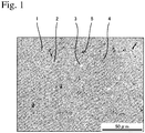
- FIG. 1 shows the electron photomicrograph, in which a light gray portion is an austenite phase 1, white particles are granular Nb carbide 2, angular grayish white particles are Zr nitride 3, dark gray particles are Cr carbide 4, and black particles are sulfide particles 5 such as MnS, etc.
- the Zr nitride particles were confirmed by analysis by an energy-dispersive X-ray spectrometer (EDS, EDAX Genesis available from AMETEK Co., Ltd.) attached to FE-SEM.
- a structure-observation test piece was cut out of each sample, and its electron photomicrographs were taken in three arbitrary fields of 500 ⁇ m x 500 ⁇ m (0.25 mm 2 ).
- the number of Zr nitride particles having equivalent circle diameters of 1.5 ⁇ m or more were counted in each field by image analysis, and averaged for three fields.
- the results in Examples 26-49 and Comparative Example 34 are shown in Table 6.
- Table 6 in the structure of each heat-resistant cast steel of Examples 26-49 containing Zr, the number of Zr nitride particles having equivalent circle diameters of 1.5 ⁇ m or more was 20-150 per a field area of 0.25 mm 2 .
Description
- The present invention relates to a heat-resistant, austenitic cast steel having excellent thermal fatigue properties suitable for exhaust members, particularly turbine housings, etc. of automobiles, and an exhaust member made thereof.
- For the purpose of environmental load reduction and environmental protection recently needed on a global scale, the cleaning of exhaust gases for reducing the emission of air-polluting materials, and the improvement of fuel efficiency (low fuel consumption) for suppressing the emission of CO2, a cause of global warming, are strongly required in automobiles. For this purpose, various technologies such as the development of engines with higher performance and fuel efficiency, the cleaning of exhaust gases, the weight reduction of car bodies, the air resistance reduction of car bodies, efficient power transmission from engines to driven systems with low loss, etc. have been developed and employed.
- Technologies for providing engines with high performance and improved fuel efficiency include the direct injection of fuel, the high pressure of fuel injection, increase in compression ratios, decrease in displacements by turbochargers, the reduction of engine weights and sizes (downsizing), etc., and are used not only in luxury cars but also in popular cars. As a result, fuel combustion tends to occur at higher temperatures and pressure, resulting in higher-temperature exhaust gases discharged from combustion chambers of engines to exhaust members. For example, the temperatures of exhaust gases are 1000°C or higher even in popular cars, like luxury sport cars, so that the surface temperatures of exhaust members tend to exceed 900°C. Because exhaust members exposed to high-temperature oxidizing gases are subjected to repeated heating/cooling cycles by the start and stop of engines in a severer oxidizing environment than ever, they are required to have higher heat resistance and durability than ever.
- Exhaust members such as turbine housings, exhaust manifolds, etc. used for automobiles have conventionally been formed by castings with high freedom of shape, because of their complicated shapes. In addition, because of their severe, high-temperature use conditions, heat-resistant cast irons such as high-Si, spheroidal graphite cast irons and Ni-resist cast irons (Ni-Cr-containing, austenitic cast irons), heat-resistant, ferritic cast steels, heat-resistant, austenitic cast steels, etc. are used. Particularly when exhaust members have surface temperatures of 900°C or higher, their materials are heat-resistant, ferritic cast steels or heat-resistant, austenitic cast steels.
- However, because the heat-resistant, ferritic cast steels usually have poor high-temperature strength at 900°C or higher, they are not suitably used in a temperature range exceeding 950°C. Materials capable of withstanding higher temperatures than heat-resistant, ferritic cast steels are heat-resistant, austenitic cast steels. For example,
WO 2005/103314 proposes a high-Cr, high-Ni, heat-resistant, austenitic cast steel comprising by mass 0.2-1.0% of C, 3% or less of Si, 2% or less of Mn, 15-30% of Cr, 6-30% of Ni, 0.5-6% (as W + 2Mo) of W and/or Mo, 0.5-5% of Nb, 0.23% or less of Al, 0.01-0.5% of N, 0.5% or less of S, and 0.07% or less of O, the balance being substantially Fe and inevitable impurities. Because this heat-resistant, austenitic cast steel has high high-temperature yield strength, oxidation resistance and room-temperature elongation, as well as excellent thermal fatigue properties particularly when exposed to a high-temperature exhaust gas at 1000°C or higher, it is suitable for exhaust members, etc. for automobile engines. - Exhaust members are required to be adapted for temperature elevation and oxidation by gases discharged from engines, and for severe use conditions. For example, in an exhaust-gas-cleaning treatment (treatment for removing harmful substance, etc. from an exhaust gas by a catalyst or a filter in an exhaust-gas-cleaning apparatus), cleaning performance should be increased by rapidly heating the catalyst for activation after the engine starts, or by supplying an exhaust gas to the catalyst or filter uniformly. For the rapid activation of a catalyst, an exhaust gas flowing through the exhaust member should suffer less temperature decrease, namely, the heat of an exhaust gas should be dissipated as little as possible. Accordingly, the exhaust member is required to be thin to have small heat mass (heat capacity) in its exhaust gas flow path. However, a thinner exhaust member suffers more temperature elevation by an exhaust gas.
- A recent trend of reducing engine displacement by turbochargers, and the size and weight of engines makes the use environment of exhaust members severer. Smaller engines are accompanied by smaller exhaust members. Because the exhaust members are made thinner for the above exhaust-gas-cleaning treatment, and because smaller exhaust members have smaller heat mass as a whole, the exhaust members tend to suffer larger temperature elevation.
- Increase in the amount of an intake gas by supercharging by turbochargers, etc. results in increase in the amount of an exhaust gas, which increases heat flow added to the exhaust member. As a result, the temperature elevation (temperature-elevating speed) of the exhaust member per a unit time increases. Because the exhaust member has thin portions and thick portions, as well as a complicated shape including portions in contact with the exhaust gas and those not in contact with the exhaust gas, temperature difference is generated in the exhaust member, through which an exhaust gas passes. In general, a metal member subjected to temperature difference, namely thermal stress by a temperature gradient, cracks tends to be cracked. Heat flow increased by supercharging leads to a higher temperature-elevating speed of an exhaust member, so that a temperature gradient increases in the exhaust member. A larger temperature gradient leads to higher thermal stress, so that the exhaust member tends to be cracked or broken. Increase in the temperature gradient of an exhaust member becomes larger as the supercharging pressure or supercharging efficiency becomes higher.
- Thus, automobile exhaust members should be adapted to temperature elevation and oxidation by exhaust gases, temperature elevation due to thinning and heat mass decrease, a larger temperature gradient by the increased heat flow, etc. Specifically, when exhaust members are exposed to exhaust gases at as high temperatures as 950-1100°C, the temperatures of exhaust members per se are elevated to 900-1050°C, near 1000°C. The exhaust members should have excellent heat resistance and durability at such high temperatures. To meet this requirement, materials forming the exhaust members are required to have excellent thermal fatigue properties, oxidation resistance, high-temperature strength, ductility (elongation), etc. Though the heat-resistant, austenitic cast steel of
WO 2005/103314 is contemplated to be used for exhaust members exposed to exhaust gases at 1000°C or higher, it is still insufficient for use in exhaust members exposed to the above severe conditions, and its thermal fatigue properties particularly need improvement. - Document
WO 2013/168770 A1 discloses a heat-resistant, austenitic cast steel having excellent heat resistance and excellent machinability, which comprises by mass 0.4-0.55% of C, 1-2% of Si, 0.5-1.5% of Mn, 18-27% of Cr, 8-22% of Ni, 1.5-2.5% of Nb, 0.01-0.3% of N, 0.1-0.2% of S, and 0.02-0.15% of Al, the balance being Fe and inevitable impurities; a machinability index I expressed by the following formula: I = 100S+75Al+0.75Mn-10C-2Nb-0.25Cr-0.15Ni-1.2N, wherein each element symbol represents % by mass of each element in the cast steel, meeting the condition of -3.0 ≤ I ≤ +14.0. Al is indispensable as an element improving machinability. - Document
EP 1 679 387 A1 discloses a heat-resistant cast steel for hydrogen producing reaction tubes which is characterized in that the cast steel comprises, in mass %, 0.1-0.5% of C, up to 2.5% of Si, up to 2.5% of Mn, 15-26% of Cr, 8-23% of Ni, 0.1-1.2% of Nb, 0.01-1.0% of Ti, 0.001-0.15% of Ce, up to 0.06% of N and the balance substantially Fe, the cast steel being 20-45 in the parameter value P represented by the following expression: P = 89.3 -78.4C + 0.1Si - 5.7Mn -1.7Cr + 0.01Ni + 2Nb + 5.3Ti - 36.5N - 50.8Ce. For the heat-resistant cast steel of this document, Ti of 0.01% and Ce of 0.001% are respectively indispensable to improve creep rupture strength and to improve high-temperature oxidation resistance. - Document
US 6 033 626 A discloses a heat-resistant cast alloy, which is excellent in resistance to surface spalling and in high-temperature strength, consisting essentially of, in % by weight, 0.1-0.6% of C, over 0% to not more than 2% of Si, over 2.36 to not more than 4% of Mn, 24.5-32% of Cr, 13-25% of Ni, 0.5-2.0% of Nb and 0.1-0.25% of N, the balance being substantially Fe. In the heat-resistant cast ally of this document, S is regarded as an inevitable impurity, and the incorporation of more than 0.04% of S is implicitly denied. - Document
JP H11-236653 A - Accordingly, an object of the present invention is to provide a heat-resistant, austenitic cast steel having excellent thermal fatigue properties near 1000°C, and an exhaust member such as a turbine housing, etc. made of this heat-resistant, austenitic cast steel.
- As a result of intensive research on a composition range of heat-resistant, austenitic cast steel, whose heat resistance, particularly thermal fatigue properties, can be improved, the inventors have found that limiting the amounts of main alloy elements such as C, Cr, Ni, Nb, etc. to proper ranges provides the heat-resistant, austenitic cast steel with drastically improved thermal fatigue properties. The present invention has been completed and is defined in the appended claims.
- The heat-resistant, austenitic cast steel of the present invention preferably has a fatigue life of 1500 cycles or more, when measured by a high-temperature, low-cycle fatigue test, which loads tensile strain and compression strain under the conditions of a test temperature of 900°C, a strain amplitude of 0.5%, a strain rate of 0.1%/second, and a compression-keeping time of 1 minute.
- Because the heat-resistant, austenitic cast steel of the present invention has excellent heat resistance and durability, as well as high thermal fatigue properties near 1000°C, exhaust members such as turbine housings, etc. made thereof can be used under severe conditions at as high temperatures as near 1000°C.
-
Fig. 1 is an electron photomicrograph of the test piece of Example 35. - The heat-resistant, austenitic cast steel of the present invention will be explained in detail below. The amounts of elements constituting the heat-resistant cast steel are expressed by "% by mass," unless otherwise mentioned.
- C improves the fluidity of a melt, castability, partially provides solid solution strengthening to a matrix, and forms carbides to improve high-temperature strength. To exhibit such functions effectively, the C content should be 0.3% or more. However, more than 0.6% of C generates excessive carbides, providing the heat-resistant cast steel with low thermal fatigue properties, machinability and ductility. Accordingly, the C content is 0.3-0.5%. The lower limit of the C content is preferably 0.35%, more preferably 0.4%. The upper limit of the C content is 0.5%.
- Si is an element acting as a deoxidizer of a melt, and effectively improving oxidation resistance and thus thermal fatigue properties. To obtain such functions, the Si content should be 0.5% or more. However, excessive Si makes the austenite structure unstable, providing the heat-resistant cast steel with deteriorated castability, and further poor machinability due to hardening. Thus, the Si content should be 3% or less. Accordingly, the Si content is 0.5-3%. The lower limit of the Si content is preferably 0.8%, more preferably 1%. The upper limit of the Si content is preferably 2%, more preferably 1.6%.
- S is combined with Mn and Cr to form sulfides such as MnS, (Mn/Cr)S, etc., whose lubricating function improves the machinability of the heat-resistant cast steel. To obtain this effect, S should be 0.01% or more. However, more than 0.5% of S tends to deteriorate the high-temperature strength and ductility of the heat-resistant cast steel, and providing the heat-resistant cast steel with poor thermal fatigue properties due to excessively formed sulfides. Accordingly, the S content is 0.05-0.5%. The lower limit of the S content is 0.05%, more preferably 0.1%. The upper limit of the S content is preferably 0.3%, more preferably 0.2%.
- Mn is effective as a deoxidizer of a melt like Si, and combined with S to form sulfides such as MnS, etc., thereby improving the machinability of the heat-resistant cast steel. To exhibit these effects, the Mn content should be 0.5% or more. However, because excessive Mn deteriorates the oxidation resistance of the heat-resistant cast steel, the Mn content should be 2% or less. Thus, the Mn content is 0.5-2%. The lower limit of the Mn content is preferably 0.7%, and the upper limit of the Mn content is preferably 1.3%.
- Cr is an element effective for austenitizing the structure of the heat-resistant cast steel together with Ni described below, thereby increasing the heat resistance (high-temperature strength and oxidation resistance) of the heat-resistant cast steel. To exhibit the effect of improving heat resistance particularly at high temperatures near 1000°C, Cr should be 15% or more. However, Cr is an element crystallizing Cr carbide based on Cr23C6 and Cr7C3. Because Cr carbide does not fit in an austenite matrix crystallographically, there are weak eutectic boundaries between Cr carbide and austenite, acting as the propagation paths of cracks. When the Cr content is more than 30%, a lot of Cr carbide is crystallized, tending to accelerate the propagation of cracks, thereby providing the heat-resistant cast steel with extremely low thermal fatigue properties and ductility. On the other hand, when excessive Cr is contained, ferrite is crystallized in the structure, resulting in low high-temperature strength. Thus, the Cr content is 15-30%. The lower limit of the Cr content is preferably 20%, more preferably 24%. The upper limit of the Cr content is preferably 28%, more preferably 26%.
- Ni is an austenite-forming element, which stabilizes the austenite structure of the heat-resistant cast steel, increases the high-temperature strength and oxidation resistance of the heat-resistant cast steel together with Cr, and improves the castability of thin exhaust members having complicated shapes. To exhibit such functions, the Ni content should be 6% or more. However, when more than 30% of Ni is contained, an increased amount of Ni dissolved in the matrix lowers the solid solution limit of C in the matrix, resulting in excessive crystallization of Cr carbide, thereby providing the heat-resistant cast steel with low thermal fatigue properties. In addition, even when more than 30% of Ni is contained, the effects of improving the above properties are saturated, leaving only economic disadvantages because of the expensiveness of the element. Accordingly, the Ni content is 6-22%. The lower limit of the Ni content is preferably 10%, more preferably 11%. The upper limit of the Ni content is 22%.
- Nb is combined with C more predominantly than Cr, to form fine Nb carbide, thereby suppressing the crystallization of Cr carbide, and indirectly improving the high-temperature strength and thermal fatigue properties of the heat-resistant cast steel. Further, Nb forms eutectic carbide with austenite, improving castability, which is important in the production of thin, complicated-shaped castings such as exhaust members. To such end, Nb should be 0.6% or more. On the other hand, when Nb exceeds 5%, a lot of hard eutectic carbide is formed in crystal grain boundaries, rather providing the heat-resistant cast steel with low high-temperature strength and thermal fatigue properties, and extremely reduced ductility because of brittleness. In addition, because excessive Nb forms fine Nb carbide particles and colonies of densely gathered eutectic carbide with austenite, making the heat-resistant cast steel less resistant to oxidation. Accordingly, the Nb content is 0.6-5%. The lower limit of the Nb content is preferably 0.8%. The upper limit of the Nb content is preferably 3%, more preferably 2.2%.
- N is a strong austenite-forming element, stabilizing the austenite matrix of the heat-resistant cast steel to improve high-temperature strength. N is also an element effective for making finer crystal grains in complicated-shaped castings, to which forging or rolling for making crystal grains finer cannot be conducted. With N contained, crystal grains become finer, thereby improving the ductility and machinability of the heat-resistant cast steel. Also, because N makes the diffusion speed of C lower, the aggregation of precipitated carbides is retarded, thereby effectively suppressing carbide particles from becoming larger, and thus preventing embrittlement. To obtain such effects, the N content should be 0.01% or more. However, more than 0.5% of N lowers the solid solution limit of C in the matrix like Ni, resulting in excessive crystallization of Cr carbide, and thus providing the heat-resistant cast steel with low thermal fatigue properties. Also, when N is contained in as much an amount as more than 0.5%, N is dissolved in the matrix in an large amount, making the heat-resistant cast steel hard, and combined with Cr and Al to precipitate large amounts of hard, brittle nitrides such as Cr2N, AlN, etc., thereby providing the heat-resistant cast steel with poor high-temperature strength and ductility. Further, excessive N accelerates the generation of gas defects such as pinholes, blowholes, etc. during casting, thereby deteriorating a casting yield. Accordingly, the N content is 0.01-0.5%. The lower limit of the N content is preferably 0.05%, more preferably 0.06%. The upper limit of the N content is preferably 0.4%, more preferably 0.2%.
- The optimization of a ratio C/N is a measure of controlling the crystallization of carbonitrides. Both of C and N, interstitial elements, are dissolved in the matrix, providing a stable austenite matrix for improved high-temperature strength. In addition, because C and N are fixed by dissolved in the matrix to form a solid solution, the amounts of carbonitrides crystallized in grain boundaries in a final solidification stage decrease, suppressing decrease in thermal fatigue properties. Particularly in the heat-resistant cast steel of the present invention having a large Cr content, planar or network-shaped Cr carbides based on Cr23C6 and Cr7C3 are crystallized in grain boundaries, resulting in extremely deteriorated thermal fatigue properties. Accordingly, C is desirably dissolved as a solid solution in the matrix as much as possible. In order that C is dissolved as a solid solution in the matrix, it may be contemplated to reduce the N content as much as possible, but N should exist in a proper amount in the heat-resistant cast steel of the present invention to improve ductility and machinability by making austenite crystal grains finer, and to effectively prevent embrittlement by suppressing the precipitated carbide from becoming larger. With C and N contained in proper amounts, the optimization of C/N is effective to accelerate the formation of a solid solution of C in the matrix. With C/N optimized, the solid solution limit of C can be elevated while keeping the addition effects of N.
- When the amount of C is small relative to that of N (small C/N), a large amount of N is dissolved as a solid solution in the matrix, lowering the solid solution limit of C. As a result, a large amount of Cr carbide is crystallized, resulting in low thermal fatigue properties. To obtain good thermal fatigue properties, C/N should be 4 or more. On the other hand, when the amount of C is large relative to that of N (large C/N), a large amount of C is dissolved as a solid solution in the matrix, lowering the solid solution limit of N. Because N has higher effect of stabilizing an austenite matrix than that of C, the suppression of forming a solid solution of N results in low high-temperature strength. To obtain good high-temperature strength, C/N should be 7 or less. Thus, C/N is 4-7. C/N is preferably 5-6.
- In the present invention, in addition to meeting the above composition range of each element, a ratio A/B of a Cr-carbide-forming index A to a Nb-carbide-forming index B expressed by the following formulae (1) and (2):


- In the formula (1), the Cr-carbide-forming index A indicating the tendency of crystallizing Cr carbide gets larger (more Cr carbide) as the amounts of C, Cr and Ni become larger, and smaller (less Cr carbide) as the amount of Nb becomes larger. In the formula (2), the Nb-carbide-forming index B indicating the tendency of crystallizing Nb carbide gets larger (more Nb carbide) proportionally as the Nb content becomes larger.
- The amounts of Cr carbide and Nb carbide crystallized are changed by the amounts of C, Cr, Ni and Nb, and when their crystallization amounts are substantially the same, the thermal fatigue properties are at maximum. Accordingly, larger A/B leads to a small amount of C fixed by Nb, resulting in a larger amount of Cr carbide crystallized, and thus lower thermal fatigue properties and ductility. On the other hand, smaller A/B leads to a larger amount of Nb carbide crystallized, despite a smaller amount of Cr carbide crystallized, resulting in lower thermal fatigue properties, high-temperature strength and ductility. To obtain good thermal fatigue properties, A/B is 0.6-1.7, more preferably 0.7-1.3, most preferably 0.8-1.2.
- To achieve a desired range of A/B, the Nb content is preferably adjusted depending on the Ni content. For example, the Nb content is desirably 0.6-1% when the Ni content is about 10%, 0.75-1.2% when the Ni content is about 13%, and 1.3-2% when the Ni content is about 20%.
- The heat-resistant, austenitic cast steel of the present invention containing Zr has a structure in which Cr carbide particles, Nb carbide particles, sulfide particles such as MnS, and Zr nitride particles are dispersed in an austenite matrix composed of fine crystal grains. Particularly when Zr nitride particles having equivalent circle diameters of 1.5 µm or more are contained in the number of 20-150 per a field area of 0.25 mm2, the heat-resistant cast steel has a strengthened matrix, thereby having improved thermal fatigue properties.
- Because oxides, nitrides and carbides such as ZrO2, ZrN, ZrC, etc. formed by Zr contained are dispersed in the matrix of the heat-resistant cast steel, to act as nuclei of forming Nb carbide and sulfides such as MnS, Nb carbide and sulfides such as MnS are finely dispersed. It is presumed that the fine dispersion of Cr carbide crystallized in a final solidification stage is not caused by nuclei of forming ZrO2, ZrN, ZrC, etc., but indirectly caused by finely dispersed Nb carbide crystallized in an early stage of solidification and fine austenite crystal grains.
- When Zr is not contained, a large amount of eutectic carbide of Nb carbide and austenite is formed densely in a colony or lamellar shape. When Nb carbide having strong oxidizing tendency is crystallized densely, Nb carbide particles are too close to each other, likely becoming vulnerable to oxidation. As a result, the heat-resistant cast steel has low oxidation resistance, and thus low thermal fatigue properties. With Zr contained, granular Nb carbide particles are finely dispersed, resulting in larger distance between Nb carbide particles, and thus lower oxidizing tendency. As a result, the heat-resistant cast steel has improved thermal fatigue properties.
- Further, Zr is combined with N to form not only ZrN functioning as nuclei for forming Nb carbide and sulfides such as MnS, etc., but also finely dispersed Zr nitride to strengthen the matrix. As a result, the heat-resistant cast steel is provided with improved thermal fatigue properties.
- When Zr is contained to obtain the above effect, Zr is preferably 0.005% or more. On the other hand, when Zr is more than 0.5%, carbonitride such as ZrN, ZrC, etc. is excessively crystallized without obtaining correspondingly increased effects, providing the heat-resistant cast steel with brittleness and lower high-temperature strength, ductility and machinability, merely resulting in economic disadvantages because Zr is an expensive element. Thus, when Zr is contained, its content is 0.005-0.5%. The lower limit of the Zr content is preferably 0.01%, more preferably 0.03%, most preferably 0.04%. The upper limit of the Zr content is preferably 0.3%, more preferably 0.2%, most preferably 0.1%.
- Inevitable impurities contained in the heat-resistant, austenitic cast steel of the present invention are mainly P, Al, W and Mo coming from the starting material and/or the deoxidizer. Because P is segregated in crystal grain boundaries, resulting in extremely low toughness, its amount is preferably as small as possible, and is 0.06% or less. Al forms inclusions such as slug of Al2O3, causing casting defects and thus deteriorating a casting yield. Al also forms hard and brittle AlN, lowering ductility and machinability. Accordingly, the amount of Al is preferably as small as possible, and is 0.05% or less. W and Mo form carbides, lowering ductility. W and Mo are also dissolved in the matrix, reducing the amount of Cr dissolved in the matrix, and thus lowering the oxidation resistance of the matrix. Further, W and Mo accelerate the crystallization of Cr carbide, deteriorating the thermal fatigue properties. Accordingly, the amounts of W and Mo are preferably as small as possible, W and Mo being 0.5% or less each, more preferably 0.5% or less in total.
- By containing Zr, the heat-resistant, austenitic cast steel of the present invention preferably has 20-150 Zr nitride particles having equivalent circle diameters 1.5 µm or more per a field area of 0.25 mm2 in the structure. With 20 or more Zr nitride particles having equivalent circle diameters of 1.5 µm or more per a field area of 0.25 mm2, the matrix is strengthened, providing the heat-resistant cast steel with improved thermal fatigue properties. Because Zr nitride particles having equivalent circle diameters of less than 1.5 µm do not have strong effects of improving thermal fatigue properties, the number of Zr nitride particles having equivalent circle diameters of 1.5 µm or more is counted in the present invention. Because Zr nitride particles are hard and brittle, more than 150 Zr nitride particles per a field area of 0.25 mm2 provide the heat-resistant cast steel with low ductility and machinability. The number of Zr nitride particles having equivalent circle diameters of 1.5 µm or more is more preferably 30-100 per a field area of 0.25 mm2. To provide the heat-resistant cast steel with improved ductility and machinability, Zr nitride particles are preferably as fine as possible. Specifically, the average equivalent circle diameter of Zr nitride particles is preferably 1.5-10 µm, more preferably 1.5-5 µm, most preferably 1.5-3 µm.
- Exhaust members are required to have long thermal fatigue lives to the repetition of start (heating) and stop (cooling) of engines. The thermal fatigue life is one of indexes representing thermal fatigue properties. The larger number of cycles until thermal fatigue failure occurs by cracking and deformation caused by repeated heating and cooling in a thermal fatigue test means a longer thermal fatigue life, and thus better thermal fatigue properties. The thermal fatigue test for evaluating a thermal fatigue life includes (a) a thermal fatigue life test (TMF: thermo-mechanical fatigue), in which a constrained material is repeatedly given a temperature amplitude by heating and cooling to cause thermal fatigue failure, with elongation and shrinkage due to heating and cooling mechanically constrained; and (b) a high-temperature, low-cycle fatigue test (LCF: low-cycle fatigue), in which a material is subjected to tension and compression with a constant strain amplitude at a constant temperature, to cause thermal fatigue failure by repeated loading of strain.
- TMF evaluating a thermal fatigue life by heating and cooling may be regarded as being close to an actual engine test. It is determined, for example, by repeating a heating/cooling cycle comprising a temperature-elevating time of 2 minutes, a temperature-keeping time of 1 minute and a cooling time of 4 minutes, 7 minutes in total, with the lowest cooling temperature of 150°C, the highest heating temperature of 1000°C, and a temperature amplitude of 850°C. Because this test needs a lot of time, and because necking occurs in the material due to expansion and shrinkage by heating and cooling during the test, the thermal fatigue life may not be evaluated precisely. On the other hand, LCF is determined by a test of repeating a tension/compression cycle comprising loading strain for 10 seconds, and keeping compression for 1 minute, 1 minute 10 seconds in total (70 seconds). Because LCF needs only a short test time, and because necking by expansion and shrinkage does not occur in the material due to a constant test temperature, LCF can evaluate the thermal fatigue life more precisely than TMF. Accordingly, both thermal fatigue tests of TMF and LCF were conducted, to evaluate the thermal fatigue properties of the heat-resistant cast steel by LCF, while using TMF for additional data.
- The heat-resistant, austenitic cast steel of the present invention preferably has a fatigue life of 1500 cycles or more, when measured by a high-temperature, low-cycle fatigue test (LCF test) with strain loaded by tension and compression, under the conditions of a test temperature of 900°C, a strain amplitude of 0.5%, a strain rate of 0.1%/second, and a compression-keeping time of 1 minute. With the LCF thermal fatigue life of 1500 cycles or more, the heat-resistant, austenitic cast steel may be regarded as having excellent thermal fatigue properties, suitable for exhaust members whose temperatures are elevated to near 1000°C by exposure to exhaust gases at 950-1100°C. The LCF thermal fatigue life is more preferably 1800 cycles or more, further preferably 1900 cycles or more, most preferably 2000 cycles or more, particularly 2200 cycles or more.
- With A/B of 0.6-1.7 and the Zr content of 0.005-0.5%, the heat-resistant, austenitic cast steel of the present invention can have a LCF thermal fatigue life of 2000 cycles or more.
- The exhaust member of the present invention is made of the above heat-resistant, austenitic cast steel. Preferred examples of the exhaust members include a turbine housing, an exhaust manifold, a turbine-housing-integrated exhaust manifold obtained by integrally casting a turbine housing and an exhaust manifold, a catalyst case, a catalyst-case-integrated exhaust manifold obtained by integrally casting a catalyst case and an exhaust manifold, and an exhaust outlet, though not restrictive, of course.
- The exhaust member of the present invention exhibits high heat resistance and durability, even when heated to 900-1050°C by exposure to an exhaust gas at 950-1100°C. Because the exhaust member of the present invention is adapted to high-temperature, severe use conditions, it enables the application of the technologies of improving the performance and fuel efficiency of engines to popular cars. It is thus expected that the exhaust member of the present invention contributes to cleaning exhaust gases of automobiles and improving the fuel efficiency.
- The present invention will be explained in more detail by Examples below without intention of restriction. Here, the amount of each element constituting the heat-resistant, austenitic cast steel is expressed by "% by mass," unless otherwise mentioned.
- The chemical compositions, C/N and A/B of the heat-resistant, austenitic cast steels of Examples 1-25 (Examples 24 and 25 are reference examples not falling under the scope of the claims) are shown in Tables 1-1 and 1-2, and the chemical compositions, C/N and A/B of the heat-resistant cast steels of Comparative Examples 1-33 are shown in Tables 2-1 and 2-2. Comparative Examples 1-33 are outside the scope of the present invention in at least one of the chemical composition, C/N and A/B. Comparative Example 33 is an example of high-Cr, high-Ni, heat-resistant, austenitic cast steels described in
WO 2005/103314 , which contains 2.8% by mass of W. Except for W in Comparative Example 33, inevitable impurities in each heat-resistant cast steel were 0.02% or less of P, 0.03% or less of Al, 0.1% or less of W, and 0.1% or less of Mo.Table 1-1 No. Composition (% by mass) C Si Mn S Cr Ni Example 1 0.30 1.45 0.97 0.140 15.4 7.9 Example 2 0.43 1.51 1.01 0.150 15.0 15.0 Example 3 0.35 1.43 0.98 0.130 18.2 10.0 Example 4 0.44 1.40 0.96 0.140 20.0 8.0 Example 5 0.45 1.46 0.98 0.150 20.0 10.0 Example 6 0.31 1.01 1.85 0.135 25.0 13.1 Example 7 0.32 1.32 0.95 0.138 24.9 14.7 Example 8 0.45 1.38 0.97 0.142 24.8 12.6 Example 9 0.46 1.46 0.99 0.144 24.9 12.9 Example 10 0.46 1.46 0.99 0.144 24.9 12.9 Example 11 0.45 1.41 0.96 0.128 25.1 12.9 Example 12 0.44 1.51 0.94 0.147 24.9 13.0 Example 13 0.44 1.40 0.96 0.142 24.5 12.7 Example 14 0.45 1.48 0.98 0.150 24.9 19.9 Example 15 0.42 1.40 0.98 0.150 24.9 20.1 Example 16 0.48 1.52 0.99 0.149 25.1 20.2 Example 17 0.46 1.46 0.93 0.148 25.0 20.0 Example 18 0.45 1.52 0.99 0.146 25.0 19.8 Example 19 0.46 1.44 0.94 0.140 24.5 20.7 Example 20 0.47 1.39 0.98 0.145 24.8 20.0 Example 21 0.43 1.49 0.92 0.141 25.0 20.0 Example 22 0.46 1.41 0.95 0.135 24.5 20.2 Example 23 0.44 1.41 1.53 0.460 24.3 20.1 Example 24 0.52 1.50 1.02 0.151 25.1 23.5 Example 25 0.58 1.55 1.06 0.274 29.8 29.5 Table 1-2 No. Composition (% by mass) Nb N C/N A/B Fe Example 1 0.60 0.041 7.3 0.6 Bal. Example 2 0.95 0.085 5.1 1.1 Bal. Example 3 0.65 0.047 7.4 0.9 Bal. Example 4 0.82 0.079 5.6 0.6 Bal. Example 5 0.98 0.080 5.6 0.7 Bal. Example 6 0.60 0.058 5.3 1.5 Bal. Example 7 0.61 0.081 4.0 1.7 Bal. Example 8 0.64 0.103 4.4 1.5 Bal. Example 9 0.75 0.085 5.4 1.3 Bal. Example 10 0.80 0.085 5.4 1.2 Bal. Example 11 1.04 0.086 5.2 0.9 Bal. Example 12 1.20 0.085 5.2 0.8 Bal. Example 13 1.44 0.083 5.3 0.6 Bal. Example 14 0.91 0.081 5.6 1.7 Bal. Example 15 1.20 0.098 4.3 1.2 Bal. Example 16 1.32 0.090 5.3 1.2 Bal. Example 17 1.47 0.082 5.6 1.0 Bal. Example 18 1.66 0.084 5.4 0.9 Bal. Example 19 1.88 0.066 7.0 0.8 Bal. Example 20 2.04 0.078 6.0 0.7 Bal. Example 21 2.10 0.074 5.8 0.7 Bal. Example 22 2.32 0.083 5.5 0.6 Bal. Example 23 1.98 0.079 5.6 0.7 Bal. Example 24 2.07 0.082 6.3 0.9 Bal. Example 25 3.61 0.084 6.9 0.6 Bal. Table 2-1 No. Composition (% by mass) C Si Mn S Cr Ni Com. Ex. 1 0.45 1.49 0.99 0.150 20.3 10.2 Com. Ex. 2 0.30 1.42 1.05 0.130 20.1 9.9 Com. Ex. 3 0.46 1.46 0.99 0.140 30.0 6.0 Com. Ex. 4 0.46 1.52 0.99 0.150 20.1 9.8 Com. Ex. 5 0.24 1.41 0.99 0.144 24.6 12.6 Com. Ex. 6 0.72 1.38 1.01 0.152 24.7 12.9 Com. Ex. 7 0.38 0.40 1.20 0.156 24.9 13.0 Com. Ex. 8 0.39 4.50 0.98 0.163 24.5 13.1 Com. Ex. 9 0.44 1.52 2.67 0.148 25.4 12.8 Com. Ex. 10 0.43 1.44 0.95 0.670 25.0 12.9 Com. Ex. 11 0.40 1.37 1.00 0.156 13.0 13.3 Com. Ex. 12 0.41 1.39 1.21 0.145 32.0 13.1 Com. Ex. 13 0.42 1.42 1.08 0.147 24.9 5.3 Com. Ex. 14 0.41 1.41 0.97 0.151 25.0 33.7 Com. Ex. 15 0.40 1.35 1.02 0.130 24.9 12.9 Com. Ex. 16 0.44 1.49 0.98 0.145 25.2 12.6 Com. Ex. 17 0.45 1.51 1.01 0.146 24.9 12.9 Com. Ex. 18 0.42 1.43 0.97 0.153 24.8 12.8 Com. Ex. 19 0.48 1.44 1.02 0.149 25.0 13.1 Com. Ex. 20 0.42 1.48 0.95 0.135 24.6 13.0 Com. Ex. 21 0.45 1.39 0.98 0.140 25.1 13.2 Com. Ex. 22 0.42 1.38 1.00 0.143 24.8 12.9 Com. Ex. 23 0.38 1.40 0.95 0.151 25.1 12.8 Com. Ex. 24 0.48 1.44 0.96 0.138 25.4 13.6 Com. Ex. 25 0.31 1.45 1.07 0.145 24.9 13.0 Com. Ex. 26 0.44 1.43 1.14 0.144 25.2 13.1 Com. Ex. 27 0.45 1.41 1.09 0.139 25.3 12.8 Com. Ex. 28 0.56 1.42 0.99 0.150 24.7 12.5 Com. Ex. 29 0.47 1.40 0.95 0.140 25.0 20.3 Com. Ex. 30 0.45 1.42 0.97 0.142 24.5 19.8 Com. Ex. 31 0.42 1.53 0.99 0.171 25.0 19.8 Com. Ex. 32 0.46 1.47 0.97 0.159 24.5 20.4 Com. Ex. 33 0.46 1.27 1.44 0.130 25.1 19.8 Table 2-2 No. Composition (% by mass) Nb N C/N A/B Fe Com. Ex. 1 0.01 0.070 6.4 82.8 Bal. Com. Ex. 2 0.18 0.074 4.1 3.4 Bal. Com. Ex. 3 0.88 0.085 5.4 0.5 Bal. Com. Ex. 4 2.04 0.257 1.8 0.3 Bal. Com. Ex. 5 0.98 0.077 3.1 0.7 Bal. Com. Ex. 6 1.01 0.083 8.7 1.2 Bal. Com. Ex. 7 1.03 0.080 4.8 0.9 Bal. Com. Ex. 8 1.05 0.074 5.3 0.9 Bal. Com. Ex. 9 0.97 0.086 5.1 1.0 Bal. Com. Ex. 10 1.06 0.079 5.4 0.9 Bal. Com. Ex. 11 1.12 0.085 4.7 0.8 Bal. Com. Ex. 12 1.04 0.084 4.9 0.9 Bal. Com. Ex. 13 0.99 0.078 5.4 0.3 Bal. Com. Ex. 14 0.98 0.083 4.9 2.7 Bal. Com. Ex. 15 0.00 0.152 2.6 - Bal. Com. Ex. 16 0.04 0.081 5.4 26.1 Bal. Com. Ex. 17 0.57 0.086 5.2 1.8 Bal. Com. Ex. 18 0.51 0.084 5.0 1.9 Bal. Com. Ex. 19 1.71 0.087 5.5 0.5 Bal. Com. Ex. 20 1.86 0.089 4.7 0.4 Bal. Com. Ex. 21 2.16 0.166 2.7 0.4 Bal. Com. Ex. 22 5.81 0.082 5.1 0.1 Bal. Com. Ex. 23 0.97 0.001 380.0 0.9 Bal. Com. Ex. 24 1.03 0.649 0.7 1.0 Bal. Com. Ex. 25 1.01 0.096 3.2 0.8 Bal. Com. Ex. 26 0.97 0.132 3.3 1.0 Bal. Com. Ex. 27 0.98 0.058 7.8 1.0 Bal. Com. Ex. 28 1.00 0.071 7.9 1.0 Bal. Com. Ex. 29 0.49 0.183 2.6 3.4 Bal. Com. Ex. 30 0.03 0.077 5.8 55.1 Bal. Com. Ex. 31 2.41 0.092 4.6 0.5 Bal. Com. Ex. 32 2.73 0.085 5.4 0.5 Bal. Com. Ex. 33 0.83 0.192 2.4 1.9 Bal. - Using a 100-kg, high-frequency melting furnace with a basic lining, each starting material of Examples 1-25 and Comparative Examples 1-33 was melted in the air, charged into a ladle at 1550-1600°C, and immediately poured into a mold for casting a 1-inch Y-block at 1500-1550°C, to obtain each cast steel sample. A test piece was cut out of each sample and subjected to the following evaluations.
- As thermal fatigue properties, the thermal fatigue life was measured by a thermal fatigue life test (TMF) and a high-temperature, low-cycle fatigue test (LCF).
- A smooth-surfaced round rod test piece of 25 mm in gauge distance and 10 mm in diameter was cut out of each 1-inch Y-block sample, attached to an electro-hydraulic servo-type material tester (Servopulser EHF-ED10TF-20L available from Shimadzu Corporation) with a constraint ratio of 0.25, to measure its thermal fatigue life by subjecting each test piece to repeated heating/cooling cycles each comprising a temperature elevation time of 2 minutes, a temperature-keeping time of 1 minute, and a cooling time of 4 minutes, 7 minutes in total, with the lowest cooling temperature of 150°C, the highest heating temperature of 1000°C, and a temperature amplitude of 850°C, in the air, thereby causing thermal fatigue failure while mechanically constraining elongation and shrinkage due to heating and cooling.
- The degree of mechanical constraint is expressed by a constraint ratio defined by [(elongation by free thermal expansion - elongation under mechanical constraint) / elongation by free thermal expansion]. For example, a constraint ratio of 1.0 means a mechanical constraint condition, in which no elongation is permitted when a test piece is heated from 150°C to 1000°C. For example, when elongation by free expansion is 2 mm, a constraint ratio of 0.5 means a mechanical constraint condition, in which only elongation of 1 mm is permitted. Accordingly, the constraint ratio of 0.5 applies a compression load during temperature elevation, and a tensile load during temperature decrease. Because the constraint ratios of actual exhaust members for automobiles are about 0.1-0.5 permitting elongation to some extent, the thermal fatigue life was evaluated at a constraint ratio of 0.25.
- The thermal fatigue life was defined as the number of heating/cooling cycles until the maximum tensile load measured in each cycle decreased to 75%, in a load-temperature diagram determined by load change by the repetition of heating and cooling, with the maximum tensile load (generated at the lowest temperature) in the second cycle as a reference (100%). The measurement results of thermal fatigue life by TMF in Examples 1-25 and Comparative Examples 1-33 are shown in Tables 3 and 4, respectively.
- To have sufficient heat resistance at about 1000°C, the thermal fatigue life measured by TMF of heating and cooling at a constraint ratio of 0.25, which is hereinafter referred to as TMF thermal fatigue life, with the highest heating temperature of 1000°C and the temperature amplitude of 850°C, is preferably 900 cycles or more. Exhaust members made of a heat-resistant cast steel having a TMF thermal fatigue life of 900 cycles or more have long lives until thermal fatigue failure occurs by cracking and deformation due to the repeated heating and cooling of engines.
- As is clear from Tables 3 and 4, all of Examples 1-25 exhibited TMF thermal fatigue lives of 900 cycles or more. Thus, when the heat-resistant, austenitic cast steel of the present invention having excellent thermal fatigue properties is used for exhaust members repeatedly subjected to heating to a temperature of about 1000°C and cooling, the exhaust members are expected to exhibit sufficient heat resistance and durability. On the other hand, any of the cast steels of Comparative Examples 1-33 exhibited a TMF thermal fatigue life of less than 900 cycles, except for Comparative Example 2. Incidentally, Comparative Example 2 exhibited a short thermal fatigue life by LCF.
- The high-temperature, low-cycle fatigue test (LCF) was conducted as follows according to "Standard for High-Temperature, Low-Cycle Fatigue Testing (JSMS-SD-7-03)" issued by The Society of Materials Science, Japan on June 2, 2003. A smooth-surfaced, flanged, round rod test piece of 25 mm in gauge distance and 10 mm in diameter was cut out of each 1-inch Y-block sample, attached to the same electro-hydraulic servo material tester as in TMF. Each test piece was repeatedly subjected to strain loaded by tension and compression at a constant temperature of 900°C in the air, each cycle comprising loading tensile strain of 0.25% for 5 seconds, loading compression strain of 0.25% for 5 seconds, and keeping compression strain of 0.25% for 60 seconds, 70 seconds in total, under the conditions of a strain amplitude of 0.5% and a strain rate of 0.1%/second. The strain amplitude was set at 0.5%, because strain of about 0.5% is presumably generated in portions of actual automobile exhaust members, in which cracking likely occurs. The strain rate was set at 0.1%/second, because it is recommended in "Standard for High-Temperature, Low-Cycle Fatigue Testing (JSMS-SD-7-03)."
- The thermal fatigue life was determined by load (stress) decrease by the repetition of tension and compression, as the number of tension/compression cycles until tension load decreased to 75% of the maximum tensile load determined by the extrapolation of the tension load change before cracking occurred. The LCF thermal fatigue life measurement results in Examples 1-25 and Comparative Examples 1-33 are shown in Tables 3 and 4, respectively.
- To have sufficient heat resistance at about 1000°C, the LCF thermal fatigue life measured by applying tensile strain and compression strain under the conditions of a test temperature of 900°C, a strain amplitude of 0.5%, a strain rate of 0.1%/second, and a compression-keeping time of 1 minute is preferably 1500 cycles or more. Exhaust members made of the heat-resistant cast steel having an LCF thermal fatigue life of 1500 cycles or more have long lives until thermal fatigue failure occurs by cracking and deformation due to the repeated heating and cooling of engines.
- As is clear from Table 3, the LCF thermal fatigue life was 1500 cycles or more in all of Examples 1-25. Among them, in Examples 9-13, 15-21 and 23, in which the Cr content was 24-26%, the Ni content was 11-22%, and A/B was 0.7-1.3, the LCF thermal fatigue life was 1800 cycles or more.
- The above results revealed that the heat-resistant, austenitic cast steels of the present invention have excellent thermal fatigue properties, and that exhaust members made thereof are expected to exhibit sufficient heat resistance and durability when repeatedly subjected to heating to temperatures of about 1000°C and cooling. On the other hand, as is clear from Table 4, any of the cast steels of Comparative Examples 1-33 had an LCF thermal fatigue life of less than 1500 cycles.
- An oxide film is formed on a surface of an exhaust member exposed to an exhaust gas (containing oxidizing gases such as sulfur oxide, nitrogen oxide, etc.) at 950-1100°C, which is discharged from an engine. As the oxidation proceeds, cracking occurs from the oxide film and propagates inside the exhaust member, and finally penetrates from the outer surface of the exhaust member to the inner surface, resulting in the leakage of an exhaust gas and the breakage of the exhaust member. To evaluate the oxidation resistance of an exhaust member at 1050°C, weight reduction by oxidation was measured by the following method. Namely, a round rod test piece of 10 mm in diameter and 20 mm in length was cut out of each 1-inch Y-block sample, kept at 1050°C for 200 hours in the air, and subjected to shot blasting to remove oxide scale, thereby determining mass change per a unit area before and after the oxidation test [weight reduction by oxidation (mg/cm2)]. The weight reductions by oxidation in Examples 1-25 and Comparative Examples 1-33 are shown in Tables 3 and 4, respectively.
- To exhibit sufficient heat resistance at about 1000°C, the weight reduction by oxidation is preferably 30 mg/cm2 or less, more preferably 20 mg/cm2 or less, most preferably 10 mg/cm2 or less. As is clear from Table 3, all of Examples 1-25 exhibited the weight reduction by oxidation of less than 30 mg/cm2, indicating that the heat-resistant, austenitic cast steel of the present invention has excellent oxidation resistance, exhibiting sufficient oxidation resistance when used for exhaust members reaching temperatures of about 1000°C. As is clear from Table 4, in any of Comparative Examples 7, 11 and 13 in which the amount of Si, Cr or Ni was too small, and Comparative Examples 9 and 22 in which the amount of Mn or Nb was too large, the weight reduction by oxidation exceeded 30 mg/cm2. This means that the cast steels of Comparative Examples 7, 9, 11, 13 and 22 cannot exhibit sufficient oxidation resistance when used for exhaust members reaching temperatures of about 1000°C.
- Exhaust members are required to be resistant to thermal deformation, even in the repeated start (heating) and stop (cooling) of engines. To secure sufficient thermal deformation resistance, it preferably has high high-temperature strength. The high-temperature strength is evaluated by 0.2-% yield strength at 1050°C (high-temperature yield strength). A smooth-surfaced, flanged, round rod test piece of 50 mm in gauge distance and 10 mm in diameter was cut out of each 1-inch Y-block sample, and attached to the same electro-hydraulic servo-type material tester as in TMF, to measure the 0.2-% yield strength (MPa) of each test piece at 1050°C in the air. The high-temperature yield strengths in Examples 1-25 and Comparative Examples 1-33 are shown in Tables 3 and 4, respectively.
- To exhibit sufficient heat resistance at about 1000°C, the 0.2-% yield strength at 1050°C is preferably 20 MPa or more. Exhaust members made of the heat-resistant cast steel having 0.2-% yield strength of 20 MPa or more at 1050°C have sufficient strength to suppress cracking and breakage at 950-1100°C under constraint. The heat-resistant, austenitic cast steel of the present invention more preferably has 0.2-% yield strength of 30 MPa or more at 1050°C.
- As is clear from Table 3, the test pieces of Examples 1-25 had high-temperature yield strength of 20 MPa or more, indicating that the heat-resistant, austenitic cast steels of the present invention have excellent high-temperature yield strength, exhibiting sufficient high-temperature strength when used for exhaust members reaching temperatures of about 1000°C. On the other hand, as is clear from Table 4, in any of Comparative Example 23 having a too small N content, and Comparative Examples 6, 8, 10, 12, 22 and 24 in which the amount of C, Si, S, Cr, Nb or N was too large, the high-temperature yield strength was less than 20 MPa, indicating that the cast steels of Comparative Examples 6, 8, 10, 12 and 22-24 had insufficient high-temperature yield strength, failing to exhibit sufficient high-temperature strength when used for exhaust members reaching temperatures of about 1000°C.
- Exhaust members are required to be resistant to thermal deformation in the repeated start (heating) and stop (cooling) of engines. To secure sufficient thermal deformation resistance, they preferably have high ductility in addition to high high-temperature yield strength. To evaluate ductility, a smooth-surfaced, flanged, round rod test piece of 50 mm in gauge distance and 10 mm in diameter was cut out of each 1-inch Y-block sample, attached to the same electro-hydraulic servo material tester as in TMF, to measure the room-temperature elongation (%) of each test piece at 25°C in the air. The room-temperature elongations in Examples 1-25 and Comparative Examples 1-33 are shown in Tables 3 and 4, respectively.
- The heat-resistant, austenitic cast steel of the present invention preferably has elongation of 2.0% or more at room temperature. When exhaust members made of the heat-resistant cast steel having room-temperature elongation of 2.0% or more are cooled from high temperatures to near room temperature, they exhibit sufficient ductility to suppress deformation and cracking, which is caused by the conversion of compression stress generated at high temperatures to tensile stress. Also, the exhaust members can be withstand mechanical vibration and shock applied during production and assembling to engines, at the time of starting automobiles, during driving automobiles, etc., resulting in suppressed cracking and breakage. The room-temperature elongation of the heat-resistant, austenitic cast steel of the present invention is more preferably 3.0% or more, most preferably 4.0% or more.
- As is clear from Table 3, the room-temperature elongation was 2.0% or more in all of Examples 1-25. This indicates that the heat-resistant, austenitic cast steels of the present invention have excellent room-temperature elongation, exhibiting sufficient thermal deformation resistance when used for exhaust members repeatedly subjected to heating and cooling. On the other hand, as is clear from Table 4, the room-temperature elongation was less than 2.0% in Comparative Examples 10, 12, 22 and 24 excessively containing S, Cr, Nb or N. This indicates that the cast steels of Comparative Examples 10, 12, 22 and 24 have insufficient room-temperature elongation, failing to exhibit sufficient thermal deformation resistance when used for exhaust members repeatedly subjected to heating and cooling.
- It was found from above that the heat-resistant, austenitic cast steels of the present invention have excellent thermal fatigue properties necessary for exhibiting heat resistance and durability required for exhaust members reaching temperatures of about 1000°C, as well as oxidation resistance, high-temperature strength and thermal deformation resistance.
Table 3 No. Properties TMF (Cycles) LCF (Cycles) Weight Reduction by Oxidation (mg/cm2) High-Temperature Yield Strength (MPa) Room-Temperature Elongation (%) Example 1 907 1520 29 72 2 Example 2 1046 1740 28 68 3 Example 3 1035 1770 25 55 4 Example 4 924 1540 27 37 5 Example 5 944 1600 24 32 5 Example 6 1097 1790 18 32 10 Example 7 1058 1680 19 31 10 Example 8 1053 1780 19 30 9 Example 9 1031 1920 20 28 8 Example 10 1206 1970 21 26 9 Example 11 1578 2010 22 25 8 Example 12 1373 1960 23 25 5 Example 13 1021 1840 23 23 6 Example 14 1121 1550 12 28 9 Example 15 1012 1890 14 27 7 Example 16 1060 1910 15 27 7 Example 17 1098 1950 15 26 7 Example 18 1002 1930 18 25 6 Example 19 1260 1910 19 24 5 Example 20 1178 1900 20 23 4 Example 21 1067 1840 20 23 4 Example 22 1079 1640 22 22 3 Example 23 1149 1810 18 23 4 Example 24 909 1540 19 24 3 Example 25 958 1520 28 21 2 Table 4 No. Properties TMF (Cycles) LCF (Cycles) Weight Reduction by Oxidation (mg/cm2) High-Temperature Yield Strength (MPa) Room-Temperature Elongation (%) Com. Ex. 1 810 1350 26 33 12 Com. Ex. 2 906 1230 27 26 10 Com. Ex. 3 713 1230 25 21 4 Com. Ex. 4 681 850 24 22 8 Com. Ex. 5 505 1090 22 22 7 Com. Ex. 6 432 860 23 12 8 Com. Ex. 7 621 1380 45 23 7 Com. Ex. 8 829 1480 21 8 4 Com. Ex. 9 860 1380 97 27 5 Com. Ex. 10 710 1440 23 15 1 Com. Ex. 11 365 810 84 46 4 Com. Ex. 12 644 1430 18 14 1 Com. Ex. 13 512 930 55 20 4 Com. Ex. 14 898 1430 20 26 3 Com. Ex. 15 566 960 17 32 12 Com. Ex. 16 860 1310 17 30 11 Com. Ex. 17 835 1390 18 28 10 Com. Ex. 18 631 1440 18 29 11 Com. Ex. 19 738 1420 20 22 6 Com. Ex. 20 704 1340 22 23 6 Com. Ex. 21 647 1070 25 22 5 Com. Ex. 22 436 870 43 11 1 Com. Ex. 23 636 940 19 18 7 Com. Ex. 24 540 1080 19 15 1 Com. Ex. 25 602 1190 19 24 8 Com. Ex. 26 828 1450 18 25 7 Com. Ex. 27 872 1340 18 25 7 Com. Ex. 28 692 1000 19 24 7 Com. Ex. 29 609 1010 11 27 9 Com. Ex. 30 721 1030 10 33 9 Com. Ex. 31 625 1250 24 22 2 Com. Ex. 32 883 1280 26 20 2 Com. Ex. 33 734 1230 9 47 5 - The chemical compositions, C/N and A/B of the heat-resistant, austenitic cast steels of Examples 26-49, and the heat-resistant cast steel of Comparative Example 34 are shown in Tables 5-1 and 5-2. Inevitable impurities in each heat-resistant cast steel were 0.02% or less of P, 0.03% or less of Al, 0.1% or less of W, and 0.1% or less of Mo.
Table 5-1 No. Composition (% by mass) C Si Mn S Cr Ni Example 26 0.45 1.39 0.97 0.142 19.8 8.3 Example 27 0.46 1.44 1.01 0.149 19.9 9.8 Example 28 0.42 1.40 0.98 0.141 24.9 13.2 Example 29 0.40 1.42 0.99 0.138 25.0 12.7 Example 30 0.41 1.45 0.95 0.154 25.1 12.9 Example 31 0.41 1.42 1.01 0.150 25.2 12.8 Example 32 0.44 1.51 1.00 0.138 24.8 13.6 Example 33 0.46 1.48 0.98 0.147 24.9 13.1 Example 34 0.45 1.49 0.95 0.148 25.1 12.9 Example 35 0.46 1.45 1.02 0.151 25.0 13.1 Example 36 0.45 1.33 1.10 0.145 25.0 13.4 Example 37 0.44 1.37 1.13 0.143 25.2 12.9 Example 38 0.43 1.42 1.08 0.152 25.1 13.0 Example 39 0.47 1.40 0.97 0.156 24.8 13.0 Example 40 0.44 1.48 0.98 0.140 25.0 19.8 Example 41 0.45 1.45 1.01 0.138 25.3 20.2 Example 42 0.46 1.42 1.00 0.145 24.8 20.0 Example 43 0.41 1.39 0.98 0.152 25.0 19.8 Example 44 0.45 1.40 1.07 0.150 25.2 19.5 Example 45 0.43 1.42 1.12 0.151 25.2 20.3 Example 46 0.46 1.41 1.02 0.147 25.0 20.4 Example 47 0.45 1.44 1.00 0.143 24.9 18.7 Example 48 0.44 0.81 1.01 0.141 24.8 19.9 Example 49 0.45 0.55 0.98 0.139 24.6 19.7 Com. Ex. 34 0.32 1.98 1.54 0.106 20.1 8.9 Table 5-2 No. Composition (% by mass) Nb N Zr C/N A/B Fe Example 26 0.62 0.079 0.053 5.7 0.9 Bal. Example 27 1.01 0.080 0.049 5.8 0.7 Bal. Example 28 0.60 0.079 0.005 5.3 1.7 Bal. Example 29 0.72 0.076 0.024 5.3 1.3 Bal. Example 30 0.65 0.081 0.017 5.1 1.5 Bal. Example 31 0.60 0.082 0.006 5.0 1.6 Bal. Example 32 0.73 0.069 0.043 6.4 1.4 Bal. Example 33 0.80 0.078 0.055 5.9 1.3 Bal. Example 34 0.86 0.080 0.017 5.6 1.1 Bal. Example 35 1.00 0.085 0.048 5.4 1.0 Bal. Example 36 1.14 0.077 0.198 5.8 0.9 Bal. Example 37 1.24 0.074 0.342 5.9 0.7 Bal. Example 38 1.42 0.078 0.063 5.5 0.6 Bal. Example 39 0.97 0.082 0.494 5.7 1.0 Bal. Example 40 0.93 0.081 0.047 5.4 1.6 Bal. Example 41 1.15 0.075 0.056 6.0 1.3 Bal. Example 42 1.27 0.083 0.043 5.5 1.2 Bal. Example 43 1.38 0.081 0.051 5.1 1.0 Bal. Example 44 1.51 0.078 0.054 5.8 1.0 Bal. Example 45 1.79 0.086 0.053 5.0 0.8 Bal. Example 46 2.04 0.088 0.087 5.2 0.7 Bal. Example 47 2.15 0.085 0.084 5.3 0.6 Bal. Example 48 1.78 0.082 0.052 5.4 0.8 Bal. Example 49 1.76 0.077 0.045 5.8 0.8 Bal. Com. Ex. 34 0.48 0.192 0.042 1.7 1.1 Bal. - Each heat-resistant cast steel of Examples 26-49 and Comparative Example 34 was produced by the same method as in Examples 1-25, to measure thermal fatigue properties, weight reduction by oxidation, high-temperature yield strength, room-temperature elongation, and the number of Zr nitride particles. The measurement results are shown in Table 6.
Table 6 No. Properties Thermal Fatigue Life (Cycles) Weight Reduction by Oxidation (mg/cm2) High-Temperature Yield Strength (MPa) Room-Temperature Elongation (%) Number of Zr Nitride Particles TMF LCF Example 26 1204 2150 7 38 4 39 Example 27 1233 2090 8 37 5 47 Example 28 1120 2000 7 39 8 24 Example 29 1424 2190 7 39 8 40 Example 30 1271 2050 7 38 8 36 Example 31 1307 2080 7 40 8 35 Example 32 1344 2100 7 38 8 48 Example 33 1450 2230 8 35 7 46 Example 34 1501 2240 8 35 7 43 Example 35 1578 2320 9 34 7 44 Example 36 1528 2280 9 34 6 75 Example 37 1514 2210 9 33 6 95 Example 38 1419 2150 11 32 5 50 Example 39 1358 2080 7 34 8 147 Example 40 1303 2030 5 43 9 42 Example 41 1439 2180 6 43 8 45 Example 42 1485 2200 6 43 8 48 Example 43 1467 2240 7 41 7 51 Example 44 1453 2260 8 40 7 49 Example 45 1487 2220 8 38 6 43 Example 46 1408 2200 9 36 5 60 Example 47 1373 2100 9 36 5 53 Example 48 1424 2180 14 34 7 51 Example 49 1397 2140 25 32 6 46 Com. Ex. 34 748 1140 35 35 5 37 - As is clear from Table 6, all of Examples 26-49 exhibited TMF thermal fatigue lives of 1000 cycles or more, and LCF thermal fatigue lives of 2000 cycles or more. These results revealed that the heat-resistant, austenitic cast steels of the present invention have excellent thermal fatigue properties, and that when they are used for exhaust members repeatedly subjected to heating to temperatures of about 1000°C and cooling, the exhaust members are expected to exhibit sufficient heat resistance and durability. On the other hand, the cast steel of Comparative Example 34 having too small a Nb content and a low C/N ratio exhibited a TMF thermal fatigue life of less than 900 cycles, and an LCF thermal fatigue life of less than 1500 cycles.
- As is clear from Table 6, the weight reduction by oxidation was less than 30 mg/cm2 in all of Examples 26-49, indicating that the heat-resistant, austenitic cast steels of the present invention have excellent oxidation resistance, exhibiting sufficient oxidation resistance when used for exhaust members reaching temperatures of about 1000°C. On the other hand, the cast steel of Comparative Example 34 having a too small Nb content with small C/N exhibited weight reduction by oxidation exceeding 30 mg/cm2. This indicates that the cast steel of Comparative Example 34 cannot exhibit sufficient oxidation resistance when used for exhaust members reaching temperatures of about 1000°C.
- As is clear from Table 6, the high-temperature yield strength was 20 MPa or more in Examples 26-49. This indicates that the heat-resistant, austenitic cast steels of the present invention have excellent high-temperature yield strength, exhibiting sufficient high-temperature strength when used for exhaust members reaching temperatures of about 1000°C.
- As is clear from Table 6, the room-temperature elongation was 2.0% or more in all of Examples 26-49. This indicates that the heat-resistant, austenitic cast steels of the present invention have excellent room-temperature elongation, exhibiting sufficient thermal deformation resistance when used for exhaust members repeatedly subjected to heating and cooling.
- As described above, The heat-resistant, austenitic cast steels of the present invention containing Zr also have not only excellent thermal fatigue properties necessary for exhibiting heat resistance and durability required for exhaust members reaching temperatures of about 1000°C, but also oxidation resistance, high-temperature strength and thermal deformation resistance.
- A structure-observing test piece cut out of a bottom portion of the 1-inch Y-block sample of Example 35 was mirror-polished, and its electron photomicrograph was taken in a field of 158 µm x 119 µm by a field-emission scanning electron microscope (FE-SEM, SU-70 available from Hitachi High-Technologies Corporation) without erosion.
Fig. 1 shows the electron photomicrograph, in which a light gray portion is an austenite phase 1, white particles aregranular Nb carbide 2, angular grayish white particles areZr nitride 3, dark gray particles areCr carbide 4, and black particles aresulfide particles 5 such as MnS, etc. The Zr nitride particles were confirmed by analysis by an energy-dispersive X-ray spectrometer (EDS, EDAX Genesis available from AMETEK Co., Ltd.) attached to FE-SEM. - A structure-observation test piece was cut out of each sample, and its electron photomicrographs were taken in three arbitrary fields of 500 µm x 500 µm (0.25 mm2). The number of Zr nitride particles having equivalent circle diameters of 1.5 µm or more were counted in each field by image analysis, and averaged for three fields. The results in Examples 26-49 and Comparative Example 34 are shown in Table 6. As is clear from Table 6, in the structure of each heat-resistant cast steel of Examples 26-49 containing Zr, the number of Zr nitride particles having equivalent circle diameters of 1.5 µm or more was 20-150 per a field area of 0.25 mm2.
Claims (3)
- A heat-resistant, austenitic cast steel having excellent thermal fatigue properties, comprising by mass
0.3-0.5% of C,
0.5-3% of Si,
0.5-2% of Mn,
15-30% of Cr,
6-22% of Ni,
0.6-5% of Nb,
0.01-0.5% of N, and
0.05-0.5% of S,
the balance being Fe and inevitable impurities,
said inevitable impurities comprising 0.06% or less of P, 0.05% or less of Al,
0.5% or less of W and 0.5% or less of Mo,
characterized in
that an amount ratio C/N of C to N is 4-7,
that a ratio A/B of a Cr-carbide-forming index A to a Nb-carbide-forming index B expressed by the following formulae (1) and (2):

that optionally
the heat-resistant, austenitic cast steel further contains 0.005-0.5% by mass of Zr,
wherein the number of Zr nitride particles having equivalent circle diameters of 1.5 µm or more in the structure is 20-150 per a field area of 0.25 mm2, wherein this number is measured using the method described in the description under the heading "Number of Zr nitride particles". - An exhaust member made of the heat-resistant, austenitic cast steel recited in claim 1.
- The exhaust member according to claim 2, which is a turbine housing, an exhaust manifold, a turbine-housing-integrated exhaust manifold, a catalyst case, a catalyst-case-integrated exhaust manifold, or an exhaust outlet.
Applications Claiming Priority (2)
| Application Number | Priority Date | Filing Date | Title |
|---|---|---|---|
| JP2014204840 | 2014-10-03 | ||
| PCT/JP2015/078228 WO2016052750A1 (en) | 2014-10-03 | 2015-10-05 | Austenitic heat-resistant cast steel having excellent thermal fatigue characteristics, and exhaust system component comprising same |
Publications (3)
| Publication Number | Publication Date |
|---|---|
| EP3202939A1 EP3202939A1 (en) | 2017-08-09 |
| EP3202939A4 EP3202939A4 (en) | 2018-04-11 |
| EP3202939B1 true EP3202939B1 (en) | 2020-01-01 |
Family
ID=55630770
Family Applications (1)
| Application Number | Title | Priority Date | Filing Date |
|---|---|---|---|
| EP15846497.4A Active EP3202939B1 (en) | 2014-10-03 | 2015-10-05 | Austenitic heat-resistant cast steel having excellent thermal fatigue characteristics, and exhaust system component comprising same |
Country Status (9)
| Country | Link |
|---|---|
| US (1) | US10815555B2 (en) |
| EP (1) | EP3202939B1 (en) |
| JP (1) | JP6481692B2 (en) |
| KR (1) | KR102453685B1 (en) |
| CN (1) | CN107075633B (en) |
| BR (1) | BR112017006063B1 (en) |
| CA (1) | CA2963369C (en) |
| MX (1) | MX2017004302A (en) |
| WO (1) | WO2016052750A1 (en) |
Families Citing this family (5)
| Publication number | Priority date | Publication date | Assignee | Title |
|---|---|---|---|---|
| JP2018070900A (en) * | 2016-10-24 | 2018-05-10 | トヨタ自動車株式会社 | Austenitic heat resistant cast steel |
| WO2018160515A1 (en) * | 2017-03-03 | 2018-09-07 | Borgwarner Inc. | Nickel and chrome based iron alloy having enhanced high temperature oxidation resistance |
| WO2019130876A1 (en) * | 2017-12-28 | 2019-07-04 | 株式会社Ihi | Heat resistant steel casting and supercharger component |
| CN114008230B (en) * | 2019-07-12 | 2022-08-23 | 日之出控股株式会社 | Austenitic heat-resistant cast steel and exhaust system component |
| CN114393176A (en) * | 2022-02-17 | 2022-04-26 | 天津水泥工业设计研究院有限公司 | Low-nickel all-austenite heat-resistant steel and preparation method and application thereof |
Family Cites Families (11)
| Publication number | Priority date | Publication date | Assignee | Title |
|---|---|---|---|---|
| JPS5729562A (en) | 1980-07-28 | 1982-02-17 | Nippon Stainless Steel Co Ltd | Heat resistant cast steel with excellent high temperature strength |
| JPH04350150A (en) * | 1990-12-11 | 1992-12-04 | Toyota Motor Corp | Austenitic heat resistant cast steel |
| JP3486713B2 (en) * | 1998-02-25 | 2004-01-13 | 株式会社クボタ | Heat-resistant cast steel with excellent high-temperature strength and heat-resistant fatigue properties for furnace coiler drum casting of reversible hot rolling mill |
| JP3486714B2 (en) * | 1998-09-25 | 2004-01-13 | 株式会社クボタ | Heat-resistant cast steel with excellent surface roughening resistance for coiler drum casting in heat-retaining furnaces of reversible hot rolling mills |
| JP2001262287A (en) * | 2000-03-22 | 2001-09-26 | Nippon Steel Corp | Austenitic stainless steel excellent in surface quality |
| KR101190997B1 (en) * | 2003-10-20 | 2012-10-16 | 가부시끼 가이샤 구보다 | Heat-resistant cast steel for reaction tube for hydrogen production being excellent in aging ductility and creep rupture strength |
| WO2005103314A1 (en) | 2004-04-19 | 2005-11-03 | Hitachi Metals, Ltd. | HIGH-Cr HIGH-Ni AUSTENITIC HEAT-RESISTANT CAST STEEL AND EXHAUST SYSTEM COMPONENT PRODUCED FROM SAME |
| JP5227359B2 (en) | 2010-04-07 | 2013-07-03 | トヨタ自動車株式会社 | Austenitic heat-resistant cast steel |
| CN104321453B (en) * | 2012-05-10 | 2016-08-24 | 日立金属株式会社 | Austenite heat-resistant cast steel that machinability is excellent and the exhaust system part being made up of it |
| JP2014210293A (en) | 2013-04-17 | 2014-11-13 | 日立ツール株式会社 | Cutting method of austenitic heat resistant cast steel |
| CN103834876B (en) * | 2014-02-28 | 2016-04-20 | 西峡县内燃机进排气管有限责任公司 | A kind of austenitic heat resistant cast steel exhaust manifold and casting technique thereof |
-
2015
- 2015-10-05 BR BR112017006063-9A patent/BR112017006063B1/en active IP Right Grant
- 2015-10-05 CN CN201580052132.1A patent/CN107075633B/en active Active
- 2015-10-05 EP EP15846497.4A patent/EP3202939B1/en active Active
- 2015-10-05 CA CA2963369A patent/CA2963369C/en active Active
- 2015-10-05 JP JP2016552192A patent/JP6481692B2/en active Active
- 2015-10-05 KR KR1020177009956A patent/KR102453685B1/en active IP Right Grant
- 2015-10-05 US US15/515,651 patent/US10815555B2/en active Active
- 2015-10-05 WO PCT/JP2015/078228 patent/WO2016052750A1/en active Application Filing
- 2015-10-05 MX MX2017004302A patent/MX2017004302A/en unknown
Non-Patent Citations (1)
| Title |
|---|
| None * |
Also Published As
| Publication number | Publication date |
|---|---|
| BR112017006063A2 (en) | 2017-12-19 |
| MX2017004302A (en) | 2017-07-14 |
| KR20170063709A (en) | 2017-06-08 |
| US10815555B2 (en) | 2020-10-27 |
| CN107075633B (en) | 2019-11-26 |
| JP6481692B2 (en) | 2019-03-13 |
| JPWO2016052750A1 (en) | 2017-08-10 |
| KR102453685B1 (en) | 2022-10-12 |
| EP3202939A1 (en) | 2017-08-09 |
| CA2963369C (en) | 2022-05-17 |
| EP3202939A4 (en) | 2018-04-11 |
| WO2016052750A1 (en) | 2016-04-07 |
| CA2963369A1 (en) | 2016-04-07 |
| US20170298489A1 (en) | 2017-10-19 |
| CN107075633A (en) | 2017-08-18 |
| BR112017006063B1 (en) | 2021-06-01 |
Similar Documents
| Publication | Publication Date | Title |
|---|---|---|
| EP1741799B1 (en) | HIGH-Cr HIGH-Ni AUSTENITIC HEAT-RESISTANT CAST STEEL AND EXHAUST SYSTEM COMPONENT PRODUCED FROM SAME | |
| EP3202939B1 (en) | Austenitic heat-resistant cast steel having excellent thermal fatigue characteristics, and exhaust system component comprising same | |
| EP1652949A1 (en) | Austenite heat-resistant spheroidal graphite cast iron | |
| US9046029B2 (en) | Heat-resistant, ferritic cast steel having excellent melt flowability, gas defect resistance, toughness and machinability, and exhaust member made thereof | |
| JP4825886B2 (en) | Ferritic spheroidal graphite cast iron | |
| EP2554703B1 (en) | Ferrite heat-resistant cast steel having excellent normal-temperature toughness and exhaust system component formed from the same | |
| EP2848710B1 (en) | Austenitic heat-resistant cast steel having excellent machinability, and part for exhaust system which comprises same | |
| US9758851B2 (en) | Heat-resistant, cast ferritic steel having excellent machinability and exhaust member made thereof | |
| KR100435324B1 (en) | Cast iron with improved oxidation resistance at high temperature |
Legal Events
| Date | Code | Title | Description |
|---|---|---|---|
| STAA | Information on the status of an ep patent application or granted ep patent |
Free format text: STATUS: THE INTERNATIONAL PUBLICATION HAS BEEN MADE |
|
| PUAI | Public reference made under article 153(3) epc to a published international application that has entered the european phase |
Free format text: ORIGINAL CODE: 0009012 |
|
| STAA | Information on the status of an ep patent application or granted ep patent |
Free format text: STATUS: REQUEST FOR EXAMINATION WAS MADE |
|
| 17P | Request for examination filed |
Effective date: 20170502 |
|
| AK | Designated contracting states |
Kind code of ref document: A1 Designated state(s): AL AT BE BG CH CY CZ DE DK EE ES FI FR GB GR HR HU IE IS IT LI LT LU LV MC MK MT NL NO PL PT RO RS SE SI SK SM TR |
|
| AX | Request for extension of the european patent |
Extension state: BA ME |
|
| DAV | Request for validation of the european patent (deleted) | ||
| DAX | Request for extension of the european patent (deleted) | ||
| A4 | Supplementary search report drawn up and despatched |
Effective date: 20180308 |
|
| RIC1 | Information provided on ipc code assigned before grant |
Ipc: C22C 38/60 20060101ALI20180303BHEP Ipc: C22C 38/48 20060101ALI20180303BHEP Ipc: C22C 38/58 20060101ALI20180303BHEP Ipc: C22C 38/02 20060101ALI20180303BHEP Ipc: C22C 38/50 20060101ALI20180303BHEP Ipc: C22C 38/04 20060101ALI20180303BHEP Ipc: C22C 38/00 20060101AFI20180303BHEP |
|
| STAA | Information on the status of an ep patent application or granted ep patent |
Free format text: STATUS: EXAMINATION IS IN PROGRESS |
|
| 17Q | First examination report despatched |
Effective date: 20190205 |
|
| GRAP | Despatch of communication of intention to grant a patent |
Free format text: ORIGINAL CODE: EPIDOSNIGR1 |
|
| STAA | Information on the status of an ep patent application or granted ep patent |
Free format text: STATUS: GRANT OF PATENT IS INTENDED |
|
| INTG | Intention to grant announced |
Effective date: 20190726 |
|
| GRAS | Grant fee paid |
Free format text: ORIGINAL CODE: EPIDOSNIGR3 |
|
| GRAA | (expected) grant |
Free format text: ORIGINAL CODE: 0009210 |
|
| STAA | Information on the status of an ep patent application or granted ep patent |
Free format text: STATUS: THE PATENT HAS BEEN GRANTED |
|
| AK | Designated contracting states |
Kind code of ref document: B1 Designated state(s): AL AT BE BG CH CY CZ DE DK EE ES FI FR GB GR HR HU IE IS IT LI LT LU LV MC MK MT NL NO PL PT RO RS SE SI SK SM TR |
|
| REG | Reference to a national code |
Ref country code: GB Ref legal event code: FG4D |
|
| REG | Reference to a national code |
Ref country code: CH Ref legal event code: EP Ref country code: AT Ref legal event code: REF Ref document number: 1219852 Country of ref document: AT Kind code of ref document: T Effective date: 20200115 |
|
| REG | Reference to a national code |
Ref country code: DE Ref legal event code: R096 Ref document number: 602015044883 Country of ref document: DE |
|
| REG | Reference to a national code |
Ref country code: IE Ref legal event code: FG4D |
|
| REG | Reference to a national code |
Ref country code: NL Ref legal event code: MP Effective date: 20200101 |
|
| REG | Reference to a national code |
Ref country code: LT Ref legal event code: MG4D |
|
| PG25 | Lapsed in a contracting state [announced via postgrant information from national office to epo] |
Ref country code: NO Free format text: LAPSE BECAUSE OF FAILURE TO SUBMIT A TRANSLATION OF THE DESCRIPTION OR TO PAY THE FEE WITHIN THE PRESCRIBED TIME-LIMIT Effective date: 20200401 Ref country code: NL Free format text: LAPSE BECAUSE OF FAILURE TO SUBMIT A TRANSLATION OF THE DESCRIPTION OR TO PAY THE FEE WITHIN THE PRESCRIBED TIME-LIMIT Effective date: 20200101 Ref country code: CZ Free format text: LAPSE BECAUSE OF FAILURE TO SUBMIT A TRANSLATION OF THE DESCRIPTION OR TO PAY THE FEE WITHIN THE PRESCRIBED TIME-LIMIT Effective date: 20200101 Ref country code: PT Free format text: LAPSE BECAUSE OF FAILURE TO SUBMIT A TRANSLATION OF THE DESCRIPTION OR TO PAY THE FEE WITHIN THE PRESCRIBED TIME-LIMIT Effective date: 20200527 Ref country code: LT Free format text: LAPSE BECAUSE OF FAILURE TO SUBMIT A TRANSLATION OF THE DESCRIPTION OR TO PAY THE FEE WITHIN THE PRESCRIBED TIME-LIMIT Effective date: 20200101 Ref country code: RS Free format text: LAPSE BECAUSE OF FAILURE TO SUBMIT A TRANSLATION OF THE DESCRIPTION OR TO PAY THE FEE WITHIN THE PRESCRIBED TIME-LIMIT Effective date: 20200101 Ref country code: FI Free format text: LAPSE BECAUSE OF FAILURE TO SUBMIT A TRANSLATION OF THE DESCRIPTION OR TO PAY THE FEE WITHIN THE PRESCRIBED TIME-LIMIT Effective date: 20200101 |
|
| PG25 | Lapsed in a contracting state [announced via postgrant information from national office to epo] |
Ref country code: HR Free format text: LAPSE BECAUSE OF FAILURE TO SUBMIT A TRANSLATION OF THE DESCRIPTION OR TO PAY THE FEE WITHIN THE PRESCRIBED TIME-LIMIT Effective date: 20200101 Ref country code: GR Free format text: LAPSE BECAUSE OF FAILURE TO SUBMIT A TRANSLATION OF THE DESCRIPTION OR TO PAY THE FEE WITHIN THE PRESCRIBED TIME-LIMIT Effective date: 20200402 Ref country code: LV Free format text: LAPSE BECAUSE OF FAILURE TO SUBMIT A TRANSLATION OF THE DESCRIPTION OR TO PAY THE FEE WITHIN THE PRESCRIBED TIME-LIMIT Effective date: 20200101 Ref country code: SE Free format text: LAPSE BECAUSE OF FAILURE TO SUBMIT A TRANSLATION OF THE DESCRIPTION OR TO PAY THE FEE WITHIN THE PRESCRIBED TIME-LIMIT Effective date: 20200101 Ref country code: IS Free format text: LAPSE BECAUSE OF FAILURE TO SUBMIT A TRANSLATION OF THE DESCRIPTION OR TO PAY THE FEE WITHIN THE PRESCRIBED TIME-LIMIT Effective date: 20200501 Ref country code: BG Free format text: LAPSE BECAUSE OF FAILURE TO SUBMIT A TRANSLATION OF THE DESCRIPTION OR TO PAY THE FEE WITHIN THE PRESCRIBED TIME-LIMIT Effective date: 20200401 |
|
| REG | Reference to a national code |
Ref country code: DE Ref legal event code: R097 Ref document number: 602015044883 Country of ref document: DE |
|
| PG25 | Lapsed in a contracting state [announced via postgrant information from national office to epo] |
Ref country code: ES Free format text: LAPSE BECAUSE OF FAILURE TO SUBMIT A TRANSLATION OF THE DESCRIPTION OR TO PAY THE FEE WITHIN THE PRESCRIBED TIME-LIMIT Effective date: 20200101 Ref country code: RO Free format text: LAPSE BECAUSE OF FAILURE TO SUBMIT A TRANSLATION OF THE DESCRIPTION OR TO PAY THE FEE WITHIN THE PRESCRIBED TIME-LIMIT Effective date: 20200101 Ref country code: EE Free format text: LAPSE BECAUSE OF FAILURE TO SUBMIT A TRANSLATION OF THE DESCRIPTION OR TO PAY THE FEE WITHIN THE PRESCRIBED TIME-LIMIT Effective date: 20200101 Ref country code: SM Free format text: LAPSE BECAUSE OF FAILURE TO SUBMIT A TRANSLATION OF THE DESCRIPTION OR TO PAY THE FEE WITHIN THE PRESCRIBED TIME-LIMIT Effective date: 20200101 Ref country code: DK Free format text: LAPSE BECAUSE OF FAILURE TO SUBMIT A TRANSLATION OF THE DESCRIPTION OR TO PAY THE FEE WITHIN THE PRESCRIBED TIME-LIMIT Effective date: 20200101 Ref country code: SK Free format text: LAPSE BECAUSE OF FAILURE TO SUBMIT A TRANSLATION OF THE DESCRIPTION OR TO PAY THE FEE WITHIN THE PRESCRIBED TIME-LIMIT Effective date: 20200101 |
|
| PLBE | No opposition filed within time limit |
Free format text: ORIGINAL CODE: 0009261 |
|
| STAA | Information on the status of an ep patent application or granted ep patent |
Free format text: STATUS: NO OPPOSITION FILED WITHIN TIME LIMIT |
|
| REG | Reference to a national code |
Ref country code: AT Ref legal event code: MK05 Ref document number: 1219852 Country of ref document: AT Kind code of ref document: T Effective date: 20200101 |
|
| 26N | No opposition filed |
Effective date: 20201002 |
|
| PG25 | Lapsed in a contracting state [announced via postgrant information from national office to epo] |
Ref country code: AT Free format text: LAPSE BECAUSE OF FAILURE TO SUBMIT A TRANSLATION OF THE DESCRIPTION OR TO PAY THE FEE WITHIN THE PRESCRIBED TIME-LIMIT Effective date: 20200101 |
|
| PG25 | Lapsed in a contracting state [announced via postgrant information from national office to epo] |
Ref country code: PL Free format text: LAPSE BECAUSE OF FAILURE TO SUBMIT A TRANSLATION OF THE DESCRIPTION OR TO PAY THE FEE WITHIN THE PRESCRIBED TIME-LIMIT Effective date: 20200101 Ref country code: SI Free format text: LAPSE BECAUSE OF FAILURE TO SUBMIT A TRANSLATION OF THE DESCRIPTION OR TO PAY THE FEE WITHIN THE PRESCRIBED TIME-LIMIT Effective date: 20200101 |
|
| REG | Reference to a national code |
Ref country code: CH Ref legal event code: PL |
|
| PG25 | Lapsed in a contracting state [announced via postgrant information from national office to epo] |
Ref country code: LU Free format text: LAPSE BECAUSE OF NON-PAYMENT OF DUE FEES Effective date: 20201005 Ref country code: MC Free format text: LAPSE BECAUSE OF FAILURE TO SUBMIT A TRANSLATION OF THE DESCRIPTION OR TO PAY THE FEE WITHIN THE PRESCRIBED TIME-LIMIT Effective date: 20200101 |
|
| REG | Reference to a national code |
Ref country code: BE Ref legal event code: MM Effective date: 20201031 |
|
| PG25 | Lapsed in a contracting state [announced via postgrant information from national office to epo] |
Ref country code: LI Free format text: LAPSE BECAUSE OF NON-PAYMENT OF DUE FEES Effective date: 20201031 Ref country code: BE Free format text: LAPSE BECAUSE OF NON-PAYMENT OF DUE FEES Effective date: 20201031 Ref country code: CH Free format text: LAPSE BECAUSE OF NON-PAYMENT OF DUE FEES Effective date: 20201031 |
|
| PG25 | Lapsed in a contracting state [announced via postgrant information from national office to epo] |
Ref country code: IE Free format text: LAPSE BECAUSE OF NON-PAYMENT OF DUE FEES Effective date: 20201005 |
|
| PG25 | Lapsed in a contracting state [announced via postgrant information from national office to epo] |
Ref country code: TR Free format text: LAPSE BECAUSE OF FAILURE TO SUBMIT A TRANSLATION OF THE DESCRIPTION OR TO PAY THE FEE WITHIN THE PRESCRIBED TIME-LIMIT Effective date: 20200101 Ref country code: MT Free format text: LAPSE BECAUSE OF FAILURE TO SUBMIT A TRANSLATION OF THE DESCRIPTION OR TO PAY THE FEE WITHIN THE PRESCRIBED TIME-LIMIT Effective date: 20200101 Ref country code: CY Free format text: LAPSE BECAUSE OF FAILURE TO SUBMIT A TRANSLATION OF THE DESCRIPTION OR TO PAY THE FEE WITHIN THE PRESCRIBED TIME-LIMIT Effective date: 20200101 |
|
| PG25 | Lapsed in a contracting state [announced via postgrant information from national office to epo] |
Ref country code: MK Free format text: LAPSE BECAUSE OF FAILURE TO SUBMIT A TRANSLATION OF THE DESCRIPTION OR TO PAY THE FEE WITHIN THE PRESCRIBED TIME-LIMIT Effective date: 20200101 Ref country code: AL Free format text: LAPSE BECAUSE OF FAILURE TO SUBMIT A TRANSLATION OF THE DESCRIPTION OR TO PAY THE FEE WITHIN THE PRESCRIBED TIME-LIMIT Effective date: 20200101 |
|
| PGFP | Annual fee paid to national office [announced via postgrant information from national office to epo] |
Ref country code: IT Payment date: 20230913 Year of fee payment: 9 Ref country code: GB Payment date: 20230831 Year of fee payment: 9 |
|
| PGFP | Annual fee paid to national office [announced via postgrant information from national office to epo] |
Ref country code: FR Payment date: 20230911 Year of fee payment: 9 |
|
| PGFP | Annual fee paid to national office [announced via postgrant information from national office to epo] |
Ref country code: DE Payment date: 20230830 Year of fee payment: 9 |