EP3202708A1 - Procédé de fabrication d'un composant horloger hybride - Google Patents
Procédé de fabrication d'un composant horloger hybride Download PDFInfo
- Publication number
- EP3202708A1 EP3202708A1 EP16154126.3A EP16154126A EP3202708A1 EP 3202708 A1 EP3202708 A1 EP 3202708A1 EP 16154126 A EP16154126 A EP 16154126A EP 3202708 A1 EP3202708 A1 EP 3202708A1
- Authority
- EP
- European Patent Office
- Prior art keywords
- plate
- metal
- hybrid
- watch component
- substrate
- Prior art date
- Legal status (The legal status is an assumption and is not a legal conclusion. Google has not performed a legal analysis and makes no representation as to the accuracy of the status listed.)
- Granted
Links
Images



Classifications
-
- G—PHYSICS
- G04—HOROLOGY
- G04B—MECHANICALLY-DRIVEN CLOCKS OR WATCHES; MECHANICAL PARTS OF CLOCKS OR WATCHES IN GENERAL; TIME PIECES USING THE POSITION OF THE SUN, MOON OR STARS
- G04B31/00—Bearings; Point suspensions or counter-point suspensions; Pivot bearings; Single parts therefor
- G04B31/06—Manufacture or mounting processes
-
- G—PHYSICS
- G04—HOROLOGY
- G04D—APPARATUS OR TOOLS SPECIALLY DESIGNED FOR MAKING OR MAINTAINING CLOCKS OR WATCHES
- G04D3/00—Watchmakers' or watch-repairers' machines or tools for working materials
- G04D3/0069—Watchmakers' or watch-repairers' machines or tools for working materials for working with non-mechanical means, e.g. chemical, electrochemical, metallising, vapourising; with electron beams, laser beams
-
- B—PERFORMING OPERATIONS; TRANSPORTING
- B81—MICROSTRUCTURAL TECHNOLOGY
- B81C—PROCESSES OR APPARATUS SPECIALLY ADAPTED FOR THE MANUFACTURE OR TREATMENT OF MICROSTRUCTURAL DEVICES OR SYSTEMS
- B81C99/00—Subject matter not provided for in other groups of this subclass
- B81C99/0075—Manufacture of substrate-free structures
- B81C99/0085—Manufacture of substrate-free structures using moulds and master templates, e.g. for hot-embossing
-
- G—PHYSICS
- G04—HOROLOGY
- G04B—MECHANICALLY-DRIVEN CLOCKS OR WATCHES; MECHANICAL PARTS OF CLOCKS OR WATCHES IN GENERAL; TIME PIECES USING THE POSITION OF THE SUN, MOON OR STARS
- G04B1/00—Driving mechanisms
- G04B1/10—Driving mechanisms with mainspring
- G04B1/14—Mainsprings; Bridles therefor
- G04B1/145—Composition and manufacture of the springs
-
- G—PHYSICS
- G04—HOROLOGY
- G04B—MECHANICALLY-DRIVEN CLOCKS OR WATCHES; MECHANICAL PARTS OF CLOCKS OR WATCHES IN GENERAL; TIME PIECES USING THE POSITION OF THE SUN, MOON OR STARS
- G04B13/00—Gearwork
- G04B13/02—Wheels; Pinions; Spindles; Pivots
-
- G—PHYSICS
- G04—HOROLOGY
- G04B—MECHANICALLY-DRIVEN CLOCKS OR WATCHES; MECHANICAL PARTS OF CLOCKS OR WATCHES IN GENERAL; TIME PIECES USING THE POSITION OF THE SUN, MOON OR STARS
- G04B15/00—Escapements
- G04B15/14—Component parts or constructional details, e.g. construction of the lever or the escape wheel
-
- G—PHYSICS
- G04—HOROLOGY
- G04B—MECHANICALLY-DRIVEN CLOCKS OR WATCHES; MECHANICAL PARTS OF CLOCKS OR WATCHES IN GENERAL; TIME PIECES USING THE POSITION OF THE SUN, MOON OR STARS
- G04B17/00—Mechanisms for stabilising frequency
- G04B17/04—Oscillators acting by spring tension
- G04B17/06—Oscillators with hairsprings, e.g. balance
- G04B17/063—Balance construction
-
- G—PHYSICS
- G04—HOROLOGY
- G04B—MECHANICALLY-DRIVEN CLOCKS OR WATCHES; MECHANICAL PARTS OF CLOCKS OR WATCHES IN GENERAL; TIME PIECES USING THE POSITION OF THE SUN, MOON OR STARS
- G04B17/00—Mechanisms for stabilising frequency
- G04B17/04—Oscillators acting by spring tension
- G04B17/06—Oscillators with hairsprings, e.g. balance
- G04B17/066—Manufacture of the spiral spring
-
- G—PHYSICS
- G04—HOROLOGY
- G04B—MECHANICALLY-DRIVEN CLOCKS OR WATCHES; MECHANICAL PARTS OF CLOCKS OR WATCHES IN GENERAL; TIME PIECES USING THE POSITION OF THE SUN, MOON OR STARS
- G04B18/00—Mechanisms for setting frequency
- G04B18/08—Component parts or constructional details
-
- G—PHYSICS
- G04—HOROLOGY
- G04B—MECHANICALLY-DRIVEN CLOCKS OR WATCHES; MECHANICAL PARTS OF CLOCKS OR WATCHES IN GENERAL; TIME PIECES USING THE POSITION OF THE SUN, MOON OR STARS
- G04B19/00—Indicating the time by visual means
- G04B19/04—Hands; Discs with a single mark or the like
- G04B19/042—Construction and manufacture of the hands; arrangements for increasing reading accuracy
-
- G—PHYSICS
- G04—HOROLOGY
- G04B—MECHANICALLY-DRIVEN CLOCKS OR WATCHES; MECHANICAL PARTS OF CLOCKS OR WATCHES IN GENERAL; TIME PIECES USING THE POSITION OF THE SUN, MOON OR STARS
- G04B19/00—Indicating the time by visual means
- G04B19/04—Hands; Discs with a single mark or the like
- G04B19/044—Mounting and setting of the hands on the axle
-
- B—PERFORMING OPERATIONS; TRANSPORTING
- B81—MICROSTRUCTURAL TECHNOLOGY
- B81B—MICROSTRUCTURAL DEVICES OR SYSTEMS, e.g. MICROMECHANICAL DEVICES
- B81B2201/00—Specific applications of microelectromechanical systems
- B81B2201/03—Microengines and actuators
- B81B2201/035—Microgears
-
- B—PERFORMING OPERATIONS; TRANSPORTING
- B81—MICROSTRUCTURAL TECHNOLOGY
- B81C—PROCESSES OR APPARATUS SPECIALLY ADAPTED FOR THE MANUFACTURE OR TREATMENT OF MICROSTRUCTURAL DEVICES OR SYSTEMS
- B81C2201/00—Manufacture or treatment of microstructural devices or systems
- B81C2201/03—Processes for manufacturing substrate-free structures
- B81C2201/034—Moulding
Definitions
- the present invention relates to a method for manufacturing a hybrid watch component, comprising at least two different materials. It also relates to a watch component as such obtained according to this method, a timepiece movement and a timepiece comprising such a hybrid watch component.
- hybrid watch components composed for example of a first part of silicon, or more generally of any micro-machinable material, and a second part of metal.
- a method of manufacturing such a hybrid watch component uses a first method of manufacturing by micromachining, in particular by deep reactive ion etching (acronym DRIE in English), to form the first part, and a second manufacturing process based on electroforming, in particular known by the acronym LIGA, for growing the second metal part.
- This second metal part can be reported a posteriori, but it is more accurate to grow it directly in combination with the first silicon part.
- the document EP1932804 discloses for example a method of manufacturing such a hybrid watch component which comprises etching a silicon wafer placed on a working substrate, on which will then be deposited a layer of photoresist forming a mold for growth of a layer of electroformed metal.
- the silicon plate has at least one through cavity which is also filled by the electroformed metal.
- the document WO2009062943 describes a method of manufacturing a silicon - metal hybrid component, characterized in that the metallic part encloses the "sandwiched" silicon part.
- the manufacturing method implements two distinct stages of growth of the metal part, respectively on each upper and lower surface of the silicon part.
- This approach improves the cohesion between the two parts of the watch component in different materials.
- it requires the implementation of a complex manufacturing process, in particular because of the obligation to return the substrate to achieve growth on the lower surface of the silicon part.
- the present invention aims to improve the manufacture of a hybrid watch component.
- this invention applies to the manufacture of any watch component comprising a first part in a first material, preferably micro-machinable, and a second part in a second different material, metal.
- a first object of the invention is to achieve a satisfactory cohesion and mechanical strength of a hybrid watch component.
- a second object of the invention is to provide a simple method of manufacturing a hybrid watch component.
- the invention also relates to a hybrid watch component comprising a first part made of a first micro-machinable material, characterized in that it comprises a second part in a metallic material different from the first material, this second part extending continuously. in one piece on the upper surface of the first part, through a through opening of the first part and on the lower surface of said first part, so that the first part is surrounded on both sides by the second part, which guarantees the mechanical maintenance between the two parts.
- the figure 1a illustrates a first step of the method of manufacturing a hybrid watch component according to the embodiment of the invention.
- This step consists in providing a working substrate 10 which will serve as a support for the manufacture of the watch component.
- This substrate is intended to be removed, that is to say that it is not part of the final watch component. It is either metal or any conductive material, or formed based on a non-conductive material, the upper surface 11 is made conductive by metallization.
- the working substrate may consist of a silicon wafer comprising a metal layer obtained by electro-deposition by PVD deposition of a wafer doped silicon or a metal plate or any other flat substrate whose upper surface conducts electrical current.
- the construction of the watch component will be carried out using a stack of layers in a direction substantially perpendicular to the upper surface 11 of the substrate 10, which we will conventionally call vertical direction z, facing upwards in the figures.
- This plane substrate likewise defines by convention a horizontal plane.
- the figure 1b illustrates the second step of the method of manufacturing a hybrid watch component which consists of depositing and structuring a first layer 12 of photosensitive resin to form the lower part of the mold for controlling the lower growth of the metal part of the hybrid watch component.
- the resin is a photosensitive resin, suitable for photolithography.
- the resin can be negative or positive. In the first case, it is designed to become insoluble or hardly soluble to a developer under the action of radiation, while in the second case, it is designed to become soluble in a developer under the action of a radiation, while the part not exposed to the radiation remains insoluble or hardly soluble.
- the resin used may be of the "SU-8" type, which is a negative photosensitive resin which polymerizes under the action of UV radiation.
- a photolithography step of the initial resin layer is performed, which consists of exposing the initial resin layer to a light radiation or insolating it through a mask comprising openings and opaque zones.
- This mask defines the pattern to be reproduced for the realization of the first level of the component to be manufactured.
- the light radiation used to irradiate or insolate the resin here is UV radiation emitted by a UV source.
- the radiation is perpendicular to the plane in which the mask extends so as to radiate only the areas of the resin located in line with the openings in the mask.
- the insolated resin zones become insensitive or insoluble to most developing liquids.
- the previous step of exposure to light radiation is optionally followed by a crosslinking heat treatment step, and then a development step.
- the development consists in eliminating the unexposed resin zones according to a process adapted to the resin used, for example by dissolving with a chemical product or by a plasma process. After dissolution, the conductive upper surface 11 of the substrate 10 appears at least on an area of the mold 13 where the resin has been removed. Any other method of the state of the art for forming a mold may alternatively be used.
- the first layer of photosensitive resin is of thickness (height in the z direction by convention) identical to the desired thickness for the lower part of the metal part of the hybrid watch component.
- the next step consists in depositing on this first layer 12 of photosensitive resin forming the mold 13 on the N1 level a silicon plate 14, forming a second level N2 of the structure superimposed on the level N1.
- This silicon plate 14 is intended to form a first portion of a first material of the final hybrid watch component.
- the method implements a step of structuring the silicon plate 14, by DRIE etching for example, so as to form at least one through opening 15 at least partially superimposed on a zone 13 without resin of the first level N1.
- the upper surface 11 of the substrate 10 remains accessible through this at least one through opening 15 of the silicon plate.
- the figure 1d illustrates the result obtained by this step.
- the through opening 15 is ideally less extensive in the less a given direction than the area without material above which it is formed, to promote the cohesion of the final component to be formed, as will be specified later.
- the lower surface of the plate 14 covers at least a portion of a zone 13 without first level resin N1.
- the method then involves a step of depositing and structuring a second layer 16 of photosensitive resin, forming a third level N3 above the upper surface of the silicon plate 14 and possibly filling at least a portion of at least a through opening 15 of the plate 14.
- the figure 1e illustrates an example of a result obtained by this step, which consists in forming a mold 17, thus extending partly on the level N3 on the upper surface of the silicon plate 14, and partly (optionally) on the the through apertures 15 of the silicon wafer to the upper surface 11 of the substrate.
- This mold 17 is formed by the combination of the mold 13 of the level N1, the through opening 15 of the level N2 and a zone without material at least partly superimposed of the level N3.
- the through opening 15 is cylindrical, and the layer 16 has a cylindrical portion of smaller diameter disposed at the center of the cylinder formed by the through opening 15, leaving an empty ring on its periphery forming an annular portion of the mold 17.
- the mold 16 ideally leaves at least one surface of the plate 14 apparent at a through opening 15, directly on an approach to this through opening 15.
- the method then uses a step of electrodepositing a metal in the mold consisting of the different photosensitive resin layers and the silicon part of the hybrid watch component.
- This metal growth intended to form a second part in a second material of the final hybrid watch component, is continued at least partly on the level N3.
- the result is illustrated on the figure 1f .
- the electroformed metal 18 forms a part of a single piece which extends from the upper surface 11 of the substrate 10 to the layer of level N3, above the silicon plate.
- the metal extends in particular both on the lower surface and on the upper surface of the plate 14, while passing through a through opening 15, which forms a sandwich structure with the aid of a metal part.
- the watch component therefore comprises a first layer on a first level N1 comprising only metal, a second layer on a second level N2 comprising metal and silicon, and a third layer on a third level N3 comprising only metal.
- the method implements a last step of releasing the hybrid watch component from its support, that is to say the substrate 10, which makes it possible to obtain the hybrid watch component 1 illustrated by FIG. figure 1g formed by a silicon part 4 coming from the silicon plate 14 used and a metal part 8 coming from the electroformed metal 18.
- the resins used have been removed, in a known manner, before or after the removal of the substrate 10 .
- the invention also relates to such a hybrid watch component obtained by this manufacturing method.
- a component therefore comprises a first part 4 in a first material, for example silicon or any other micro-machinable material, and a second metal part.
- This second part 8 forms a continuous zone which extends on the upper surface 5 of the first part 4, passes through the first part 4 over its entire thickness and then extends on the lower surface 6 of said first part 4. This results that the first part 4 is trapped between two portions of the second part 8, which ensures the mechanical maintenance between the two parts.
- the second portion 8 is obtained in one piece, which guarantees its maximum strength while allowing its simple formation by a single electroforming step.
- the clock component further comprises a cylindrical through opening 9 within the second portion 8, which allows to insert an axis of rotation, for example, or to form a metal insert for driving the component hybrid watchmaker.
- the first part of the hybrid watch component may be in any micro-machinable material such as silicon, diamond, quartz or a ceramic.
- the micro-machinable material used may consist of two or more layers, or of several plates superimposed on each other, for example a so-called SOI silicon plate.
- the hybrid watch component may have more than two parts, at least a third portion of a third material distinct from the two materials, which may be a micro-machinable material or an electroformed metal, associated with the architecture in a manner similar to the first two materials.
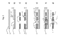
- the second step of forming a mold 13 of level N1 is followed by the production of a second layer 19 of resin of level N2, directly superimposed on the level N1, to achieve the result illustrated by FIG. figure 2b .
- This second layer 19 advantageously makes it possible to produce positioning pins.
- the silicon plate 14 is independently structured, for example by a DRIE method, to form through openings 15, at least one corresponding to a positioning pin and at least one intended to be superimposed on a zone 13 without resin of the first level mold N1.
- this structured plate can undergo other treatments, such as treatment by oxidation, doping or any other technique (nitriding, annealing, ALD layer, CVD) to give it the required properties.
- the structured plate is then associated with the structure previously formed as illustrated in FIG. Figure 2c , so that a through opening is traversed by a positioning pin.
- This architecture ensures precise positioning of the silicon wafer on the level N2, as represented by the figure 2d , in particular a good alignment and a precise superimposition of its (or its) through opening 15 above a zone 13 without material of the first level N1.
- the silicon plate 14 is thus held by the resin, both vertically by the first N1 level resin layer and horizontally by at least one resin positioning pin formed by the layer 19.
- complementary structuring processing, micromachining
- the hybrid watch component obtained represented by the figure 2g , is very similar to the one illustrated by the figure 1 boy Wut. It further comprises a through opening 2 formed only in the first part 4.
- the manufacturing method described by the two previous embodiments may comprise other variants.
- the method may comprise an intermediate metallization step between two steps described above, so as to form an electrically conductive layer on the non-conductive surfaces of resin and / or silicon, to ensure a correct deposition of the metal, for example on the shoulders.
- the photosensitive resin deposition and structuring steps can be multiple within the same step, in order to create molds of more complex shape and finally a component of more complex structure.
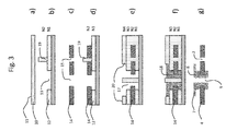
- Figures 3a to 3g illustrate a second variant embodiment of the manufacturing method, in which only the differences will be explained.
- the first steps relating to Figures 3a to 3d correspond to the steps relating to Figures 2a to 2d of the previously described variant.
- the method comprises arranging and structuring a layer 16 of resin on a level N3 and then arranging and structuring an additional layer of resin on a level N4, forming a mold 17 extending over four levels N1 to N4 instead of three in the previous variant.
- the next stage of electroplating is similar to that made with reference to the figure 2f , but on an additional level N4.
- the hybrid watch component obtained represented by the figure 3g , differs from the previous components in that it comprises a metal structure 7, for example wheel type, not in direct contact with the silicon part 4 of the watch component, while having a total cohesion.
- This second variant thus makes it possible to share the two parts of the watch component (for example silicon / metal wheel).
- first resin layer directly deposited on the substrate of the embodiments in two (or more) distinct layers, in a similar manner.
- the manufacturing method described above can be used for the manufacture of watch components such as, by way of illustrative examples and not limiters, an anchor, a jumper, a wheel, a pinion, a rake, a spring, a pendulum, a cam, or a bridge.
- the invention also relates to a hybrid watch component obtained by the method described above, as well as to a watch movement and a timepiece, for example a wristwatch, comprising such a hybrid watch component.
- the latter can be a needle with a metal insert for hunting, as represented by the figure 4a , or a counterbalanced needle for balancing, as represented by figure 4b .
- the hybrid watch component may be an anchor with a metal insert for driving, as represented by the figure 5a , or an anchor with metal pallets, as represented by the figure 5b .
- the hybrid watch component may be a balance with an inertia / weight ratio optimized as represented by the figure 6 .
- the hybrid watch component can be an anchor wheel with metal teeth as represented by the figure 7a , an anchor wheel with metal insert as represented by the figure 7b , or an anchor wheel with flexible metal structure as represented by the Figure 7c .
- the hybrid watch component can be a spiral with a metal flexible ferrule as represented by the figure 8a , a hairspring with a metal hairspring which is provided to allow attachment of the outer end of the hairspring or a metal pegging system, as shown by the figure 8b , a spiral with metal inserts for hunting on the spiral carrier as represented by the figure 8c , a hairspring with metal insert for the hunt at the ferrule as represented by the figure 8d .
- the manufacture of such a hairspring uses the variant of the manufacturing method described above, carrying out a preliminary structuring and independent of an oxidized silicon plate, in particular to form the turns which are advantageously made of oxidized silicon in order to give them optimum performance.
- the hybrid watch component may be a spring with the functional silicon part and the metal fastening part as represented by the figure 9 .
Landscapes
- Physics & Mathematics (AREA)
- General Physics & Mathematics (AREA)
- Engineering & Computer Science (AREA)
- Manufacturing & Machinery (AREA)
- Metallurgy (AREA)
- Microelectronics & Electronic Packaging (AREA)
- Optics & Photonics (AREA)
- Plasma & Fusion (AREA)
- Micromachines (AREA)
Abstract
Description
- La présente invention concerne un procédé de fabrication d'un composant horloger hybride, comprenant au moins deux matériaux différents. Elle porte aussi sur un composant horloger en tant que tel obtenu selon ce procédé, un mouvement de pièce d'horlogerie et une pièce d'horlogerie comprenant un tel composant horloger hybride.
- Il est connu de fabriquer des composants horlogers hybrides composés par exemple d'une première partie en silicium, ou plus généralement en tout matériau micro-usinable, et d'une seconde partie en métal. Un procédé de fabrication d'un tel composant horloger hybride utilise un premier procédé de fabrication par micro-usinage, notamment par gravure ionique réactive profonde (acronyme DRIE en anglais), pour former la première partie, et un second procédé de fabrication basé sur l'électroformage, notamment connu par l'acronyme LIGA, pour faire croître la seconde partie en métal. Cette seconde partie métallique peut être rapportée a posteriori, mais il est plus précis de la faire croître directement en combinaison avec la première partie en silicium.
- Le document
EP1932804 décrit par exemple une méthode de fabrication d'un tel composant horloger hybride qui comprend la gravure d'une plaque de silicium placée sur un substrat de travail, sur laquelle sera ensuite déposée une couche de résine photosensible (photoresist) formant un moule pour la croissance d'une couche de métal électroformée. La plaque en silicium comporte au moins une cavité traversante qui est aussi comblée par le métal électroformé. Cette technique apporte l'avantage de garantir la précision de positionnement des deux matériaux distincts du composant horloger. Il en résulte donc un composant horloger qui comprend un premier niveau partiellement en silicium et partiellement en métal et un second niveau en métal, superposé sur la surface supérieure du premier niveau. Une liaison dite intime entre les deux matériaux distincts du composant obtenu est assurée par la croissance de la partie métallique le long des flancs du silicium, au niveau de la cavité traversante du premier niveau. Toutefois, cette liaison n'est ni chimique, ni mécaniquement résistante, car elle ne repose que sur la seule rugosité de ces flancs, ce qui peut s'avérer trop faible pour assurer la cohésion de l'ensemble lorsqu'il est soumis à certaines contraintes ou à une variation de température importante. Ainsi, les composants horlogers ainsi obtenus présentent un risque de décohésion entre les deux matériaux, c'est-à-dire au niveau de la liaison entre le métal et le silicium. - Pour pallier ces inconvénients, le document
WO2009062943 décrit un procédé de fabrication d'un composant hybride silicium - métal, caractérisé en ce que la partie métallique enserre la partie en silicium « en sandwich ». Pour cela, le procédé de fabrication met en oeuvre deux étapes distinctes de croissance de la partie métallique, respectivement sur chaque surface supérieure et inférieure de la partie en silicium. Cette approche améliore la cohésion entre les deux parties du composant horloger en matériaux différents. Toutefois, elle nécessite la mise en oeuvre d'un procédé de fabrication complexe, notamment du fait de l'obligation de retourner le substrat pour réaliser la croissance sur la surface inférieure de la partie en silicium. En complément, on constate de plus une faiblesse au niveau de l'interface entre les différentes couches distinctes de métal formées par les deux étapes distinctes de croissance de la partie métallique. - Ainsi, la présente invention a pour objet d'améliorer la fabrication d'un composant horloger hybride. Notamment, cette invention s'applique à la fabrication de tout composant horloger comprenant une première partie dans un premier matériau, de préférence micro-usinable, et une seconde partie dans un second matériau différent, en métal.
- Plus précisément, un premier objet de l'invention est de permettre d'atteindre une cohésion et une résistance mécanique satisfaisante d'un composant horloger hybride.
- Un second objet de l'invention est de proposer un procédé de fabrication simple d'un composant horloger hybride.
- A cet effet, l'invention concerne un procédé de fabrication d'un composant horloger hybride, caractérisé en ce qu'il comprend les étapes suivantes :
- Structurer au moins une plaque d'un premier matériau micro-usinable de sorte à former au moins une ouverture traversante au sein de la plaque, ladite plaque structurée étant destinée à former une première partie du composant horloger hybride ;
- Déposer un métal par électroformage, de sorte que le métal s'étende au travers l'ouverture traversante et sur les deux faces supérieure et inférieure de la plaque d'un seul tenant résultant d'une même étape d'électroformage, le métal électroformé étant destiné à former une seconde partie du composant horloger hybride.
- L'invention porte aussi sur un composant horloger hybride comprenant une première partie en un premier matériau micro-usinable, caractérisé en ce qu'il comprend une seconde partie dans un matériau métallique différent du premier matériau, cette seconde partie s'étendant de manière continue d'un seul tenant sur la surface supérieure de la première partie, au travers une ouverture traversante de la première partie puis sur la surface inférieure de ladite première partie, de sorte que la première partie se trouve entourée de part et d'autre par la seconde partie, ce qui garantit le maintien mécanique entre les deux parties.
- L'invention est plus particulièrement définie par les revendications.
- Ces objets, caractéristiques et avantages de la présente invention seront exposés en détail dans la description suivante de modes de réalisation particuliers faits à titre non-limitatif en relation avec les figures jointes parmi lesquelles :
- Les
figures 1a à 1g illustrent les étapes successives d'un procédé de fabrication d'un composant horloger hybride selon un mode de réalisation de l'invention. - Les
figures 2a à 2g illustrent les étapes successives d'un procédé de fabrication d'un composant horloger hybride selon une variante du mode de réalisation de l'invention. - Les
figures 3a à 3g illustrent les étapes successives d'un procédé de fabrication d'un composant horloger hybride selon une deuxième variante du mode de réalisation de l'invention - Les
figures 4 à 9 illustrent différents composants horlogers hybrides selon le mode de réalisation de l'invention. - Pour une raison de simplification, nous utiliserons les termes « métal » et « métallique » dans la description suivante pour désigner un matériau métallique ou un alliage métallique. De plus, les mêmes références seront utilisées pour des éléments identiques ou similaires dans les différentes variantes de réalisation de l'invention.
- La
figure 1a illustre une première étape du procédé de fabrication d'un composant horloger hybride selon le mode de réalisation de l'invention. Cette étape consiste à se munir d'un substrat 10 de travail qui servira de support à la fabrication du composant horloger. Ce substrat est destiné à être retiré, c'est-à-dire qu'il ne fait pas partie du composant horloger final. Il est soit en métal ou en tout matériau conducteur, soit formé à base d'un matériau non conducteur, dont la surface supérieure 11 est rendue conductrice par métallisation. Ainsi, le substrat de travail peut être constitué d'une plaque de silicium comportant une couche métallique obtenue par dépôt PVD, par électroformage, d'une plaque de silicium dopé ou d'une plaque métallique ou par tout autre substrat plat dont la surface supérieure conduit le courant électrique. - La construction du composant horloger va être réalisée à l'aide d'un empilement de couches dans une direction sensiblement perpendiculaire à la surface supérieure 11 du substrat 10, que nous appellerons par convention direction verticale z, orientée vers le haut sur les figures. Ce substrat 10 plan définit de même par convention un plan horizontal.
- La
figure 1b illustre la seconde étape du procédé de fabrication d'un composant horloger hybride qui consiste à déposer et structurer une première couche 12 de résine photosensible afin de former la partie inférieure du moule destiné à contrôler la croissance inférieure de la partie métallique du composant horloger hybride. - De manière connue, la résine est une résine photosensible, adaptée à la photolithographie. La résine peut être négative ou positive. Dans le premier cas, elle est conçue pour devenir insoluble ou difficilement soluble à un révélateur sous l'action d'un rayonnement, alors que, dans le second cas, elle est conçue pour devenir soluble à un révélateur sous l'action d'un rayonnement, alors que la partie non exposée au rayonnement reste insoluble ou difficilement soluble. Dans l'exemple particulier du mode de réalisation, la résine utilisée peut être de type « SU-8 », qui est une résine photosensible négative qui polymérise sous l'action d'un rayonnement UV. Une étape de photolithographie de la couche initiale de résine est réalisée, qui consiste à exposer à une radiation lumineuse ou insoler la couche initiale de résine à travers un masque comprenant des ouvertures et des zones opaques. Ce masque définit le motif à reproduire pour la réalisation du premier niveau du composant à fabriquer. Les radiations lumineuses utilisées pour irradier ou insoler la résine sont ici des rayonnements UV émis par une source UV. Les rayonnements sont perpendiculaires au plan dans lequel s'étend le masque de manière à n'irradier que les zones de la résine situées au droit des ouvertures ménagées dans le masque. Dans l'exemple de réalisation particulier décrit ici, les zones de résine insolées deviennent insensibles ou insolubles à la plupart des liquides de développement. L'étape précédente d'exposition à des radiations lumineuses est suivie optionnellement d'une étape de traitement thermique de réticulation, puis d'une étape de développement. Le développement consiste à éliminer les zones de résine non exposées selon un procédé adapté à la résine utilisée, par exemple par dissolution avec un produit chimique ou par un procédé plasma. Après dissolution, la surface supérieure 11 conductrice du substrat 10 apparaît au moins sur une zone du moule 13 où la résine a été éliminée. Toute autre méthode de l'état de la technique permettant de former un moule peut en variante être utilisée.
- A l'issue de cette étape, on obtient donc le moule 13 et la structure illustrée par la
figure 1b , dans laquelle la surface supérieure 11 conductrice du substrat 10 est recouverte d'un moule 13 en résine sur une couche formant un premier niveau N1. Avantageusement, la première couche de résine photosensible est d'épaisseur (hauteur dans la direction z par convention) identique à l'épaisseur souhaitée pour la partie inférieure de la partie métallique du composant horloger hybride. - L'étape suivante, illustrée par la
figure 1c , consiste à déposer sur cette première couche 12 de résine photosensible formant le moule 13 sur le niveau N1 une plaque 14 de silicium, formant un second niveau N2 de la structure, superposé au niveau N1. Cette plaque 14 de silicium est destinée à former une première partie en un premier matériau du composant horloger hybride final. - Ensuite, le procédé met en oeuvre une étape de structuration de la plaque 14 de silicium, par gravure DRIE par exemple, de manière à former au moins une ouverture traversante 15 au moins partiellement superposée à une zone 13 sans résine du premier niveau N1. En remarque, la surface supérieure 11 du substrat 10 reste donc accessible par cette au moins une ouverture traversante 15 de la plaque en silicium. La
figure 1d illustre le résultat obtenu par cette étape. En remarque, l'ouverture traversante 15 est idéalement moins étendue dans au moins une direction donnée que la zone sans matière au-dessus de laquelle elle est formée, pour favoriser la cohésion du composant final qui sera formé, comme cela sera précisé par la suite. Autrement dit, la surface inférieure de la plaque 14 recouvre au moins une partie d'une zone 13 sans résine de premier niveau N1. - Le procédé met ensuite en oeuvre une étape consistant à déposer et structurer une deuxième couche 16 de résine photosensible, formant un troisième niveau N3 au-dessus de la surface supérieure de la plaque 14 en silicium et remplissant éventuellement au moins une partie d'au moins une ouverture traversante 15 de la plaque 14. La
figure 1e illustre un exemple de résultat obtenu par cette étape, qui consiste à former un moule 17, s'étendant donc en partie sur le niveau N3 sur la surface supérieure de la plaque 14 en silicium, et en partie (de manière optionnelle) à l'intérieur des ouvertures traversantes 15 de la plaque en silicium, jusqu'à la surface supérieure 11 du substrat. Ce moule 17 est donc formé par la combinaison du moule 13 du niveau N1, l'ouverture traversante 15 du niveau N2 et une zone sans matière au moins en partie superposée du niveau N3. Il s'étend depuis la surface supérieure 11 du substrat 10 jusqu'à la surface supérieure du niveau N3. Dans l'exemple illustré, l'ouverture traversante 15 est cylindrique, et la couche 16 présente une partie cylindrique de plus petit diamètre disposé au centre du cylindre formé par l'ouverture traversante 15, laissant un anneau vide sur son pourtour formant une partie annulaire du moule 17. Au niveau N3, le moule 16 laisse idéalement au moins une surface de la plaque 14 apparente au niveau d'une ouverture traversante 15, directement sur un abord de cette ouverture traversante 15. - Le procédé met ensuite en oeuvre une étape qui consiste à électrodéposer un métal dans le moule constitué par les différentes couches de résine photosensible et la partie en silicium du composant horloger hybride. Cette croissance de métal, destinée à former une seconde partie en un second matériau du composant horloger hybride final, est poursuivie au moins en partie sur le niveau N3. Le résultat est illustré sur la
figure 1f . Il apparait donc que le métal électroformé 18 forme une partie d'un seul tenant qui s'étend depuis la surface supérieure 11 du substrat 10 jusqu'à la couche de niveau N3, au-dessus de la plaque en silicium. Le métal s'étend notamment à la fois sur la surface inférieure et sur la surface supérieure de la plaque 14, tout en la traversant par une ouverture traversante 15, ce qui forme une structure sandwich à l'aide d'une partie métallique d'un seul tenant formée par une seule et même étape d'électroformage. Le composant horloger comprend donc une première couche sur un premier niveau N1 ne comprenant que du métal, une seconde couche sur un second niveau N2 comprenant du métal et du silicium, et une troisième couche sur un troisième niveau N3 ne comprenant que du métal. - Enfin, le procédé met en oeuvre une dernière étape de libération du composant horloger hybride de son support, c'est-à-dire le substrat 10, qui permet d'obtenir le composant horloger hybride 1 illustré par la
figure 1g , formé par une partie en silicium 4 provenant de la plaque 14 de silicium utilisée et une partie en métal 8 provenant du métal électroformé 18. En complément, les résines utilisées ont été supprimées, de manière connue, avant ou après le retrait du substrat 10. - L'invention porte aussi sur un tel composant horloger hybride obtenu par ce procédé de fabrication. Un tel composant comprend donc une première partie 4 dans un premier matériau, par exemple du silicium ou tout autre matériau micro-usinable, et une seconde partie en métal. Cette seconde partie 8 forme une zone continue qui s'étend sur la surface supérieure 5 de la première partie 4, traverse la première partie 4 sur toute son épaisseur puis s'étend sur la surface inférieure 6 de ladite première partie 4. Il en résulte que la première partie 4 est emprisonnée entre deux portions de la seconde partie 8, ce qui garantit le maintien mécanique entre les deux parties. D'autre part, la seconde partie 8 est obtenue d'un seul tenant, ce qui garantit sa résistance maximale tout en permettant sa formation simple par une seule étape d'électroformage. Selon le mode de réalisation illustré, le composant horloger comprend de plus une ouverture traversante cylindrique 9 au sein de la seconde partie 8, ce qui permet d'insérer un axe de rotation par exemple, ou de former un insert métallique pour le chassage du composant horloger hybride.
- La première partie du composant horloger hybride peut être dans tout matériau micro-usinable comme par exemple le silicium, le diamant, le quartz ou une céramique. En variante, le matériau micro-usinable utilisé peut être constitué de deux ou plusieurs couches, ou de plusieurs plaques superposées les unes aux autres comme par exemple une plaque de silicium dite SOI.
- De plus, le composant horloger hybride peut comporter plus de deux parties, au moins un troisième partie en un troisième matériau distinct des deux matériaux, qui peut être un matériau micro-usinable ou un métal électroformé, associé à l'architecture de manière similaire aux deux premiers matériaux.
- Les
figures 2a à 2f illustrent une variante de réalisation, dans laquelle seules les différences vont être explicitées. - Selon cette variante du procédé, la seconde étape de formation d'un moule 13 de niveau N1 est suivie de la réalisation d'une seconde couche 19 de résine de niveau N2, directement superposée au niveau N1, pour atteindre le résultat illustré par la
figure 2b . Cette seconde couche 19 permet avantageusement de réaliser des goupilles de positionnement. - Ensuite et comme illustré par la
figure 2c , la plaque 14 en silicium est structurée de manière indépendante, par exemple par une méthode DRIE, pour former des ouvertures traversantes 15, dont au moins une correspondant à une goupille de positionnement et au moins une destinée à être superposée à une zone 13 sans résine du moule de premier niveau N1. En remarque, cette plaque structurée peut subir d'autres traitements, comme un traitement par oxydation, par dopage ou par toute autre technique (nitruration, recuit, avec couche ALD, CVD) visant à lui conférer les propriétés requises. La plaque structurée est ensuite associée à la structure précédemment formée comme illustré à lafigure 2c , de sorte qu'une ouverture traversante soit traversée par une goupille de positionnement. Cette architecture garantit un positionnement précis de la plaque de silicium sur le niveau N2, comme représenté par lafigure 2d , notamment un bon alignement et une superposition précise de son (ou de ses) ouverture traversante 15 au-dessus d'une zone 13 sans matière du premier niveau N1. En remarque, la plaque 14 en silicium est ainsi maintenue par la résine, tant de manière verticale par la première couche de résine de niveau N1 qu'horizontalement par au moins une goupille de positionnement en résine formé par la couche 19. Naturellement, il est aussi possible en option d'ajouter des structurations (traitement, micro-usinage) complémentaires à la plaque 14 de silicium après sa disposition sur le niveau N2 de l'architecture précédente. - Les étapes suivantes, illustrées par les
figures 2e à 2g correspondent respectivement aux étapes illustrées par lesfigures 1e à 1g décrites précédemment. - Le composant horloger hybride obtenu, représenté par la
figure 2g , se présente de manière très similaire à celui illustré par lafigure 1 g. Il comprend de plus une ouverture traversante 2 formée uniquement dans la première partie 4. - Le procédé de fabrication décrit par les deux variantes de réalisation précédentes peut comprendre d'autres variantes de réalisation.
- Par exemple, le procédé peut comprendre une étape intermédiaire de métallisation entre deux étapes décrites précédemment, de manière à former une couche électriquement conductrice sur les surfaces non conductrices de résine et/ou de silicium, pour assurer une déposition correcte du métal, par exemple sur les épaulements.
- Selon une autre variante, les étapes de déposition et structuration de résine photosensible peuvent être multiples au sein d'une même étape, afin de créer des moules de forme plus complexe et finalement un composant de structure plus complexe.
- En variante, il est possible d'ajouter une ou plusieurs autres couches de résine pour obtenir une structure plus complexe.
- A cet effet, Les
figures 3a à 3g illustrent une seconde variante de réalisation du procédé de fabrication, dans laquelle seules les différences vont être explicitées. - Les premières étapes relatives aux
figures 3a à 3d correspondent aux étapes relatives auxfigures 2a à 2d de la variante précédemment décrite. - Ensuite, le procédé comprend la disposition et structuration d'une couche 16 de résine sur un niveau N3 puis la disposition et structuration d'une couche 20 supplémentaire de résine sur un niveau N4, formant un moule 17 s'étendant sur quatre niveaux N1 à N4 au lieu de trois dans la variante précédente.
- L'étape suivante d'électrodéposition, dont le résultat est illustré par la
figure 3f , s'apparente à celle réalisée en référence à lafigure 2f , mais sur un niveau supplémentaire N4. - Le composant horloger hybride obtenu, représenté par la
figure 3g , se différencie des composants précédents en ce qu'il comprend une structure en métal 7, par exemple de type roue, non en contact direct avec la partie en silicium 4 du composant horloger, tout en présentant une cohésion totale. Cette seconde variante permet ainsi un partage des deux parties du composant horloger (par exemple silicium/roue métallique). - Il est évidemment également possible de structurer la première couche de résine directement déposée sur le substrat des réalisations en deux (ou plus) couches distinctes, de manière analogue.
- Le procédé de fabrication décrit précédemment peut être utilisé pour la fabrication de composants horlogers tels que, à titre d'exemples illustratifs et non limitatifs, une ancre, un sautoir, une roue, un pignon, un râteau, un ressort, un balancier, une came, ou encore un pont.
- L'invention porte aussi sur un composant horloger hybride obtenu par le procédé décrit précédemment, ainsi que sur un mouvement horloger et une pièce d'horlogerie, par exemple une montre-bracelet, comprenant un tel composant horloger hybride.
- Ce dernier peut être une aiguille avec insert métallique pour le chassage, comme représenté par la
figure 4a , ou une aiguille avec contrepoids pour équilibrage, comme représenté par lafigure 4b . - Le composant horloger hybride peut être une ancre avec insert métallique pour le chassage, comme représenté par la
figure 5a , ou une ancre avec palettes métalliques, comme représenté par lafigure 5b . - Le composant horloger hybride peut être un balancier avec un rapport inertie/poids optimisé comme représenté par la
figure 6 . - Le composant horloger hybride peut être une roue d'ancre avec dents métalliques comme représenté par la
figure 7a , une roue d'ancre avec insert métalliques comme représenté par lafigure 7b , ou une roue d'ancre avec structure métallique flexible comme représenté par lafigure 7c . - Le composant horloger hybride peut être un spiral avec virole flexible métallique comme représenté par la
figure 8a , un spiral avec un porte-spiral en métal qui est prévu pour permettre la fixation de l'extrémité extérieure du spiral ou un système de pitonnage en métal, comme représenté par lafigure 8b , un spiral avec inserts métalliques pour le chassage sur le porte-spiral comme représenté par lafigure 8c , un spiral avec insert métallique pour le chassage à la virole comme représenté par lafigure 8d . La fabrication d'un tel spiral utilise la variante du procédé de fabrication décrit précédemment, réalisant une structuration préalable et indépendante d'une plaque en silicium oxydé, notamment pour former les spires qui sont avantageusement réalisées en silicium oxydé afin de leur conférer les performances optimales. - Le composant horloger hybride peut être un ressort avec la partie fonctionnelle en silicium et la partie d'attache en métal comme représenté par la
figure 9 .
Claims (12)
- Procédé de fabrication d'un composant horloger hybride, caractérisé en ce qu'il comprend les étapes suivantes:- Structurer au moins une plaque (14) d'un premier matériau micro-usinable de sorte à former au moins une ouverture traversante (15) au sein de la plaque (14), ladite plaque (14) structurée étant destinée à former une première partie (4) du composant horloger hybride ;- Déposer un métal par électroformage, de sorte que le métal s'étende au travers l'ouverture traversante (15) et sur les deux faces supérieure et inférieure de la plaque (14) d'un seul tenant résultant d'une même étape d'électroformage, le métal électroformé étant destiné à former une seconde partie (8) du composant horloger hybride.
- Procédé de fabrication d'un composant horloger hybride selon la revendication précédente, caractérisé en ce qu'il comprend les étapes suivantes :- se munir d'un substrat (10) dont au moins la surface supérieure (11) est conductrice ;- former un moule (13) en résine au-dessus de la surface supérieure (11) du substrat (10), le moule (13) comprenant au moins une zone sans matière au-dessus du substrat (10) ;- structurer au moins une plaque (14) d'un premier matériau micro-usinable et disposer la au moins une plaque (14) au-dessus du moule (13) en résine formé à l'étape précédente ou inversement, disposer au moins une plaque (14) d'un premier matériau micro-usinable au-dessus du moule (13) en résine formé à l'étape précédente et structurer la au moins une plaque (14), de sorte à former au moins une ouverture traversante (15) de la au moins une plaque (14) au moins partiellement superposée à une zone sans matière du moule (12) en résine formé à l'étape précédente ;- former un moule (17) en résine au-dessus de la plaque (14), comprenant des zones sans matière s'étendant depuis la surface supérieure (11) du substrat (10) jusqu'à la surface supérieure de l'empilement, notamment au niveau d'une ouverture traversante (15) de la plaque (14) ;- Déposer un métal ou un alliage par électroformage de sorte que le métal s'étende depuis la surface supérieure (11) du substrat (10) jusqu'au dessus de la plaque (14) ;- libérer le composant horloger hybride par le retrait du substrat (10).
- Procédé de fabrication d'un composant horloger hybride selon la revendication précédente, caractérisé en ce qu'il comprend les étapes complémentaires suivantes :- former au moins une ouverture traversante (15) dans la au moins une plaque (14) superposée à une zone sans matière du moule (13) en résine de sorte que la face inférieure de la plaque (14) recouvre au moins partiellement la zone sans matière du moule (13) ; et- former un moule (17) en résine au-dessus de la plaque (14) qui laisse libre au moins une partie de la surface supérieure de la plaque (14) au niveau d'une ouverture traversante (15) de la plaque (14).
- Procédé de fabrication d'un composant horloger hybride selon la revendication 2 ou 3, caractérisé en ce qu'il comprend une étape de formation d'une seconde couche (19) en résine au-dessus du moule (13) en résine formé au-dessus de la surface supérieure (11) du substrat (10), la seconde couche (19) formant au moins une goupille de positionnement permettant la disposition postérieure d'une plaque (14) structurée dont une ouverture traversante vient coopérer avec une goupille de positionnement pour assurer son maintien horizontal.
- Procédé de fabrication d'un composant horloger hybride selon l'une des revendications 2 à 4, caractérisé en ce que le substrat (10) est constitué d'une plaque de silicium comportant une couche métallique, notamment obtenue par dépôt PVD, par électroformage, ou d'une plaque de silicium dopé ou d'une plaque métallique.
- Procédé de fabrication d'un composant horloger hybride selon l'une des revendications 2 à 5, caractérisé en ce que l'étape consistant à former un moule (13) en résine au-dessus de la surface supérieure (11) du substrat (10) forme un moule (13) dont l'épaisseur correspond à la hauteur de métal disposée sur la face inférieure (6) de la première partie (4) du composant horloger hybride.
- Procédé de fabrication d'un composant horloger hybride selon l'une des revendications précédentes, caractérisé en ce qu'il fait partie du groupe comportant une aiguille, une ancre, un balancier, un pignon, une roue d'ancre, un spiral, un ressort.
- Composant horloger hybride comprenant une première partie (4) en un premier matériau micro-usinable, caractérisé en ce qu'il comprend une seconde partie (8) dans un matériau métallique différent du premier matériau, cette seconde partie (8) s'étendant de manière continue d'un seul tenant sur la surface supérieure (5) de la première partie (4), au travers une ouverture traversante de la première partie (4) puis sur la surface inférieure (6) de ladite première partie (4), de sorte que la première partie (4) se trouve entourée de part et d'autre par la seconde partie (8), ce qui garantit le maintien mécanique entre les deux parties (4, 8).
- Composant horloger hybride selon la revendication précédente, caractérisé en ce qu'il comprend une ouverture traversante cylindrique (9) au sein de la seconde partie (8), pour former un insert métallique apte à recevoir un axe de rotation ou pour le chassage du composant horloger hybride.
- Composant horloger hybride selon la revendication 8 ou 9, caractérisé en ce qu'il est :- une aiguille avec insert métallique pour le chassage, ou- une aiguille avec contrepoids pour équilibrage, ou- une ancre avec insert métallique pour le chassage, ou- une ancre avec palettes métalliques, ou- un balancier avec un rapport inertie/poids optimisé, ou- une roue d'ancre avec insert métalliques, ou- une roue d'ancre avec structure métallique flexible, ou- un spiral avec virole flexible métallique, ou- un spiral avec porte-spiral en métal, ou- un spiral avec inserts métalliques pour le chassage sur un porte-spiral, ou- un spiral avec insert métallique pour le chassage à la virole, ou- un ressort avec la partie fonctionnelle en silicium et la partie d'attache en métal.
- Mouvement d'horlogerie, caractérisé en ce qu'il comprend un composant horloger hybride selon l'une des revendications 8 à 10.
- Pièce d'horlogerie, notamment montre-bracelet, caractérisée en ce qu'elle comprend un mouvement d'horlogerie selon la revendication précédente.
Priority Applications (5)
| Application Number | Priority Date | Filing Date | Title |
|---|---|---|---|
| EP16154126.3A EP3202708B1 (fr) | 2016-02-03 | 2016-02-03 | Procédé de fabrication d'un composant horloger hybride |
| US15/417,854 US10359738B2 (en) | 2016-02-03 | 2017-01-27 | Process for manufacturing a hybrid timepiece component |
| JP2017017182A JP6964414B2 (ja) | 2016-02-03 | 2017-02-02 | ハイブリッド型時計部品の製造方法 |
| CN201710063435.4A CN107065501B (zh) | 2016-02-03 | 2017-02-03 | 用于制造混合钟表组件的方法 |
| US16/440,662 US20190294118A1 (en) | 2016-02-03 | 2019-06-13 | Process for manufacturing a hybrid timepiece component |
Applications Claiming Priority (1)
| Application Number | Priority Date | Filing Date | Title |
|---|---|---|---|
| EP16154126.3A EP3202708B1 (fr) | 2016-02-03 | 2016-02-03 | Procédé de fabrication d'un composant horloger hybride |
Publications (2)
| Publication Number | Publication Date |
|---|---|
| EP3202708A1 true EP3202708A1 (fr) | 2017-08-09 |
| EP3202708B1 EP3202708B1 (fr) | 2023-05-03 |
Family
ID=55299372
Family Applications (1)
| Application Number | Title | Priority Date | Filing Date |
|---|---|---|---|
| EP16154126.3A Active EP3202708B1 (fr) | 2016-02-03 | 2016-02-03 | Procédé de fabrication d'un composant horloger hybride |
Country Status (4)
| Country | Link |
|---|---|
| US (2) | US10359738B2 (fr) |
| EP (1) | EP3202708B1 (fr) |
| JP (1) | JP6964414B2 (fr) |
| CN (1) | CN107065501B (fr) |
Cited By (3)
| Publication number | Priority date | Publication date | Assignee | Title |
|---|---|---|---|---|
| EP3748437A1 (fr) * | 2019-06-07 | 2020-12-09 | Rolex Sa | Fabrication d'un composant horloger |
| CN113253594A (zh) * | 2020-02-12 | 2021-08-13 | 尼瓦洛克斯-法尔股份有限公司 | 尤其用于钟表的具有柔性条带的一件式硅装置的制造方法 |
| EP3926413A1 (fr) * | 2020-06-17 | 2021-12-22 | Rubattel et Weyermann S.A. | Formation d'un objet tridimensionnel sur un cadran |
Families Citing this family (5)
| Publication number | Priority date | Publication date | Assignee | Title |
|---|---|---|---|---|
| EP3956731B1 (fr) * | 2019-04-15 | 2026-05-20 | Rolex Sa | Composant horloger de type came |
| EP3779607A1 (fr) * | 2019-08-16 | 2021-02-17 | Nivarox-FAR S.A. | Procédé de réalisation d'un assemblage d'un ensemble organe de maintien élastique - composant d'horlogerie avec un élément de support |
| EP3839626B1 (fr) * | 2019-12-18 | 2023-10-11 | Nivarox-FAR S.A. | Procede de fabrication d'un composant horloger |
| USD928009S1 (en) * | 2020-02-05 | 2021-08-17 | Cheng Qiuting | Second hand for a watch |
| EP4407382A1 (fr) * | 2023-01-25 | 2024-07-31 | Rolex Sa | Ressort spiral pour mouvement horloger |
Citations (4)
| Publication number | Priority date | Publication date | Assignee | Title |
|---|---|---|---|---|
| EP1932804A2 (fr) | 2006-12-11 | 2008-06-18 | Mimotec S.A. | Pièces mixtes silicium/métal et méthodes de fabrication s'y référant |
| WO2009062943A1 (fr) | 2007-11-16 | 2009-05-22 | Nivarox-Far S.A. | Pièce de micromécanique composite silicium-métal et son procédé de fabrication |
| JP2012167808A (ja) * | 2011-01-27 | 2012-09-06 | Seiko Instruments Inc | 機械部品、機械組立体、機械部品の製造方法および時計 |
| CH706645A1 (fr) * | 2012-06-26 | 2013-12-31 | Cornel Marxer | Système d'accouplement solidaire d'une pièce en matériau cassant à une axe métallique. |
Family Cites Families (5)
| Publication number | Priority date | Publication date | Assignee | Title |
|---|---|---|---|---|
| US6242163B1 (en) * | 1998-08-31 | 2001-06-05 | Board Of Trustees Of The Leland Stanford Junior University | Shape deposition manufacturing of microscopic ceramic and metallic parts using silicon molds |
| JP5317635B2 (ja) * | 2007-11-30 | 2013-10-16 | 株式会社半導体エネルギー研究所 | 微小電気機械式装置の作製方法 |
| CH701972A2 (fr) * | 2009-10-07 | 2011-04-15 | Nivarox Sa | Rouage avec mobile monté fou en matériau micro-usinable, son procédé de fabrication et pièce d'horlogerie comportant un tel rouage. |
| EP2908183B1 (fr) * | 2014-02-14 | 2018-04-18 | ETA SA Manufacture Horlogère Suisse | Spiral d'horlogerie |
| JP6529516B2 (ja) * | 2014-12-12 | 2019-06-12 | シチズン時計株式会社 | 電鋳部品の製造方法 |
-
2016
- 2016-02-03 EP EP16154126.3A patent/EP3202708B1/fr active Active
-
2017
- 2017-01-27 US US15/417,854 patent/US10359738B2/en active Active
- 2017-02-02 JP JP2017017182A patent/JP6964414B2/ja active Active
- 2017-02-03 CN CN201710063435.4A patent/CN107065501B/zh active Active
-
2019
- 2019-06-13 US US16/440,662 patent/US20190294118A1/en not_active Abandoned
Patent Citations (4)
| Publication number | Priority date | Publication date | Assignee | Title |
|---|---|---|---|---|
| EP1932804A2 (fr) | 2006-12-11 | 2008-06-18 | Mimotec S.A. | Pièces mixtes silicium/métal et méthodes de fabrication s'y référant |
| WO2009062943A1 (fr) | 2007-11-16 | 2009-05-22 | Nivarox-Far S.A. | Pièce de micromécanique composite silicium-métal et son procédé de fabrication |
| JP2012167808A (ja) * | 2011-01-27 | 2012-09-06 | Seiko Instruments Inc | 機械部品、機械組立体、機械部品の製造方法および時計 |
| CH706645A1 (fr) * | 2012-06-26 | 2013-12-31 | Cornel Marxer | Système d'accouplement solidaire d'une pièce en matériau cassant à une axe métallique. |
Cited By (5)
| Publication number | Priority date | Publication date | Assignee | Title |
|---|---|---|---|---|
| EP3748437A1 (fr) * | 2019-06-07 | 2020-12-09 | Rolex Sa | Fabrication d'un composant horloger |
| US12447648B2 (en) | 2019-06-07 | 2025-10-21 | Rolex Sa | Manufacture of a horology component |
| CN113253594A (zh) * | 2020-02-12 | 2021-08-13 | 尼瓦洛克斯-法尔股份有限公司 | 尤其用于钟表的具有柔性条带的一件式硅装置的制造方法 |
| EP3926413A1 (fr) * | 2020-06-17 | 2021-12-22 | Rubattel et Weyermann S.A. | Formation d'un objet tridimensionnel sur un cadran |
| WO2021255043A1 (fr) * | 2020-06-17 | 2021-12-23 | Rubattel Et Weyermann S.A. | Formation d'un objet tridimensionnel sur un cadran |
Also Published As
| Publication number | Publication date |
|---|---|
| EP3202708B1 (fr) | 2023-05-03 |
| US20170220004A1 (en) | 2017-08-03 |
| US10359738B2 (en) | 2019-07-23 |
| CN107065501B (zh) | 2023-10-20 |
| JP6964414B2 (ja) | 2021-11-10 |
| JP2017138314A (ja) | 2017-08-10 |
| CN107065501A (zh) | 2017-08-18 |
| US20190294118A1 (en) | 2019-09-26 |
Similar Documents
| Publication | Publication Date | Title |
|---|---|---|
| EP3202708B1 (fr) | Procédé de fabrication d'un composant horloger hybride | |
| EP2347036B1 (fr) | Procédé liga hétérogène | |
| EP2229470B1 (fr) | Procédé de fabrication d'une microstructure métallique et microstructure obtenue selon ce procédé | |
| EP2105807B1 (fr) | Spiral à élévation de courbe monobloc et son procédé de fabrication | |
| EP2257856B1 (fr) | Organe régulateur monobloc et son procédé de fabrication | |
| EP2145237A2 (fr) | Composant horloger et son procédé de fabrication | |
| EP3454122B1 (fr) | Procede de fabrication par technologie liga d'une microstructure metallique comportant au moins deux niveaux | |
| EP4381352A1 (fr) | Procédé de fabrication d'un composant horloger | |
| EP3839659B1 (fr) | Procédé de décoration d'une pièce mécanique | |
| EP4381349A1 (fr) | Procédé de fabrication d'un composant horloger | |
| WO2009115470A1 (fr) | Spiral monobloc en matériau à base de silicium et son procédé de fabrication | |
| EP3839624A1 (fr) | Procede de fabrication d'un composant horloger et composant obtenu selon ce procede | |
| EP3839627B1 (fr) | Methode de fabrication d'un micromoule pour electroformage de composants micromecaniques | |
| WO2009083487A2 (fr) | Procédé de fabrication d'une microstructure métallique et microstructure obtenue selon ce procédé | |
| EP3168058B1 (fr) | Procédé de fabrication d'une pièce métallique avec au moins un motif a illusion d'optique | |
| EP3951512B1 (fr) | Procede de fabrication d'une piece comprenant au moins un motif metallise en trois dimensions | |
| EP3670440A1 (fr) | Procédé de fabrication d'un composant horloger | |
| EP3748437A1 (fr) | Fabrication d'un composant horloger | |
| EP3786722A1 (fr) | Procede de decoration d'une piece mecanique | |
| EP3453787B1 (fr) | Procede de fabrication d'un lot de pieces de micromecanique multi-niveau en metal | |
| EP3467151B1 (fr) | Moule pour galvanoplastie et son procédé de fabrication | |
| EP3839625A1 (fr) | Procede de fabrication d'un composant horloger et composant obtenu selon ce procede | |
| EP4564105A1 (fr) | Procédé de fabrication d'un balancier | |
| EP4663814A1 (fr) | Procédé de fabrication d'un moule de galvanoplastie ou de croissance métallique | |
| CH716363B1 (fr) | Procédé de décoration d'une pièce mécanique. |
Legal Events
| Date | Code | Title | Description |
|---|---|---|---|
| PUAI | Public reference made under article 153(3) epc to a published international application that has entered the european phase |
Free format text: ORIGINAL CODE: 0009012 |
|
| STAA | Information on the status of an ep patent application or granted ep patent |
Free format text: STATUS: THE APPLICATION HAS BEEN PUBLISHED |
|
| AK | Designated contracting states |
Kind code of ref document: A1 Designated state(s): AL AT BE BG CH CY CZ DE DK EE ES FI FR GB GR HR HU IE IS IT LI LT LU LV MC MK MT NL NO PL PT RO RS SE SI SK SM TR |
|
| AX | Request for extension of the european patent |
Extension state: BA ME |
|
| STAA | Information on the status of an ep patent application or granted ep patent |
Free format text: STATUS: REQUEST FOR EXAMINATION WAS MADE |
|
| 17P | Request for examination filed |
Effective date: 20180208 |
|
| RBV | Designated contracting states (corrected) |
Designated state(s): AL AT BE BG CH CY CZ DE DK EE ES FI FR GB GR HR HU IE IS IT LI LT LU LV MC MK MT NL NO PL PT RO RS SE SI SK SM TR |
|
| STAA | Information on the status of an ep patent application or granted ep patent |
Free format text: STATUS: EXAMINATION IS IN PROGRESS |
|
| 17Q | First examination report despatched |
Effective date: 20201210 |
|
| GRAP | Despatch of communication of intention to grant a patent |
Free format text: ORIGINAL CODE: EPIDOSNIGR1 |
|
| STAA | Information on the status of an ep patent application or granted ep patent |
Free format text: STATUS: GRANT OF PATENT IS INTENDED |
|
| INTG | Intention to grant announced |
Effective date: 20221130 |
|
| GRAS | Grant fee paid |
Free format text: ORIGINAL CODE: EPIDOSNIGR3 |
|
| GRAA | (expected) grant |
Free format text: ORIGINAL CODE: 0009210 |
|
| STAA | Information on the status of an ep patent application or granted ep patent |
Free format text: STATUS: THE PATENT HAS BEEN GRANTED |
|
| AK | Designated contracting states |
Kind code of ref document: B1 Designated state(s): AL AT BE BG CH CY CZ DE DK EE ES FI FR GB GR HR HU IE IS IT LI LT LU LV MC MK MT NL NO PL PT RO RS SE SI SK SM TR |
|
| REG | Reference to a national code |
Ref country code: GB Ref legal event code: FG4D Free format text: NOT ENGLISH |
|
| REG | Reference to a national code |
Ref country code: DE Ref legal event code: R096 Ref document number: 602016079125 Country of ref document: DE |
|
| REG | Reference to a national code |
Ref country code: AT Ref legal event code: REF Ref document number: 1564469 Country of ref document: AT Kind code of ref document: T Effective date: 20230515 Ref country code: CH Ref legal event code: EP |
|
| REG | Reference to a national code |
Ref country code: IE Ref legal event code: FG4D Free format text: LANGUAGE OF EP DOCUMENT: FRENCH |
|
| P01 | Opt-out of the competence of the unified patent court (upc) registered |
Effective date: 20230529 |
|
| REG | Reference to a national code |
Ref country code: LT Ref legal event code: MG9D |
|
| REG | Reference to a national code |
Ref country code: NL Ref legal event code: MP Effective date: 20230503 |
|
| REG | Reference to a national code |
Ref country code: AT Ref legal event code: MK05 Ref document number: 1564469 Country of ref document: AT Kind code of ref document: T Effective date: 20230503 |
|
| PG25 | Lapsed in a contracting state [announced via postgrant information from national office to epo] |
Ref country code: SE Free format text: LAPSE BECAUSE OF FAILURE TO SUBMIT A TRANSLATION OF THE DESCRIPTION OR TO PAY THE FEE WITHIN THE PRESCRIBED TIME-LIMIT Effective date: 20230503 Ref country code: PT Free format text: LAPSE BECAUSE OF FAILURE TO SUBMIT A TRANSLATION OF THE DESCRIPTION OR TO PAY THE FEE WITHIN THE PRESCRIBED TIME-LIMIT Effective date: 20230904 Ref country code: NO Free format text: LAPSE BECAUSE OF FAILURE TO SUBMIT A TRANSLATION OF THE DESCRIPTION OR TO PAY THE FEE WITHIN THE PRESCRIBED TIME-LIMIT Effective date: 20230803 Ref country code: NL Free format text: LAPSE BECAUSE OF FAILURE TO SUBMIT A TRANSLATION OF THE DESCRIPTION OR TO PAY THE FEE WITHIN THE PRESCRIBED TIME-LIMIT Effective date: 20230503 Ref country code: ES Free format text: LAPSE BECAUSE OF FAILURE TO SUBMIT A TRANSLATION OF THE DESCRIPTION OR TO PAY THE FEE WITHIN THE PRESCRIBED TIME-LIMIT Effective date: 20230503 Ref country code: AT Free format text: LAPSE BECAUSE OF FAILURE TO SUBMIT A TRANSLATION OF THE DESCRIPTION OR TO PAY THE FEE WITHIN THE PRESCRIBED TIME-LIMIT Effective date: 20230503 |
|
| PG25 | Lapsed in a contracting state [announced via postgrant information from national office to epo] |
Ref country code: RS Free format text: LAPSE BECAUSE OF FAILURE TO SUBMIT A TRANSLATION OF THE DESCRIPTION OR TO PAY THE FEE WITHIN THE PRESCRIBED TIME-LIMIT Effective date: 20230503 Ref country code: PL Free format text: LAPSE BECAUSE OF FAILURE TO SUBMIT A TRANSLATION OF THE DESCRIPTION OR TO PAY THE FEE WITHIN THE PRESCRIBED TIME-LIMIT Effective date: 20230503 Ref country code: LV Free format text: LAPSE BECAUSE OF FAILURE TO SUBMIT A TRANSLATION OF THE DESCRIPTION OR TO PAY THE FEE WITHIN THE PRESCRIBED TIME-LIMIT Effective date: 20230503 Ref country code: LT Free format text: LAPSE BECAUSE OF FAILURE TO SUBMIT A TRANSLATION OF THE DESCRIPTION OR TO PAY THE FEE WITHIN THE PRESCRIBED TIME-LIMIT Effective date: 20230503 Ref country code: IS Free format text: LAPSE BECAUSE OF FAILURE TO SUBMIT A TRANSLATION OF THE DESCRIPTION OR TO PAY THE FEE WITHIN THE PRESCRIBED TIME-LIMIT Effective date: 20230903 Ref country code: HR Free format text: LAPSE BECAUSE OF FAILURE TO SUBMIT A TRANSLATION OF THE DESCRIPTION OR TO PAY THE FEE WITHIN THE PRESCRIBED TIME-LIMIT Effective date: 20230503 Ref country code: GR Free format text: LAPSE BECAUSE OF FAILURE TO SUBMIT A TRANSLATION OF THE DESCRIPTION OR TO PAY THE FEE WITHIN THE PRESCRIBED TIME-LIMIT Effective date: 20230804 |
|
| PG25 | Lapsed in a contracting state [announced via postgrant information from national office to epo] |
Ref country code: FI Free format text: LAPSE BECAUSE OF FAILURE TO SUBMIT A TRANSLATION OF THE DESCRIPTION OR TO PAY THE FEE WITHIN THE PRESCRIBED TIME-LIMIT Effective date: 20230503 |
|
| PG25 | Lapsed in a contracting state [announced via postgrant information from national office to epo] |
Ref country code: SK Free format text: LAPSE BECAUSE OF FAILURE TO SUBMIT A TRANSLATION OF THE DESCRIPTION OR TO PAY THE FEE WITHIN THE PRESCRIBED TIME-LIMIT Effective date: 20230503 |
|
| PG25 | Lapsed in a contracting state [announced via postgrant information from national office to epo] |
Ref country code: SM Free format text: LAPSE BECAUSE OF FAILURE TO SUBMIT A TRANSLATION OF THE DESCRIPTION OR TO PAY THE FEE WITHIN THE PRESCRIBED TIME-LIMIT Effective date: 20230503 Ref country code: SK Free format text: LAPSE BECAUSE OF FAILURE TO SUBMIT A TRANSLATION OF THE DESCRIPTION OR TO PAY THE FEE WITHIN THE PRESCRIBED TIME-LIMIT Effective date: 20230503 Ref country code: RO Free format text: LAPSE BECAUSE OF FAILURE TO SUBMIT A TRANSLATION OF THE DESCRIPTION OR TO PAY THE FEE WITHIN THE PRESCRIBED TIME-LIMIT Effective date: 20230503 Ref country code: EE Free format text: LAPSE BECAUSE OF FAILURE TO SUBMIT A TRANSLATION OF THE DESCRIPTION OR TO PAY THE FEE WITHIN THE PRESCRIBED TIME-LIMIT Effective date: 20230503 Ref country code: DK Free format text: LAPSE BECAUSE OF FAILURE TO SUBMIT A TRANSLATION OF THE DESCRIPTION OR TO PAY THE FEE WITHIN THE PRESCRIBED TIME-LIMIT Effective date: 20230503 Ref country code: CZ Free format text: LAPSE BECAUSE OF FAILURE TO SUBMIT A TRANSLATION OF THE DESCRIPTION OR TO PAY THE FEE WITHIN THE PRESCRIBED TIME-LIMIT Effective date: 20230503 |
|
| REG | Reference to a national code |
Ref country code: DE Ref legal event code: R097 Ref document number: 602016079125 Country of ref document: DE |
|
| PLBE | No opposition filed within time limit |
Free format text: ORIGINAL CODE: 0009261 |
|
| STAA | Information on the status of an ep patent application or granted ep patent |
Free format text: STATUS: NO OPPOSITION FILED WITHIN TIME LIMIT |
|
| 26N | No opposition filed |
Effective date: 20240206 |
|
| PG25 | Lapsed in a contracting state [announced via postgrant information from national office to epo] |
Ref country code: SI Free format text: LAPSE BECAUSE OF FAILURE TO SUBMIT A TRANSLATION OF THE DESCRIPTION OR TO PAY THE FEE WITHIN THE PRESCRIBED TIME-LIMIT Effective date: 20230503 |
|
| PG25 | Lapsed in a contracting state [announced via postgrant information from national office to epo] |
Ref country code: SI Free format text: LAPSE BECAUSE OF FAILURE TO SUBMIT A TRANSLATION OF THE DESCRIPTION OR TO PAY THE FEE WITHIN THE PRESCRIBED TIME-LIMIT Effective date: 20230503 Ref country code: IT Free format text: LAPSE BECAUSE OF FAILURE TO SUBMIT A TRANSLATION OF THE DESCRIPTION OR TO PAY THE FEE WITHIN THE PRESCRIBED TIME-LIMIT Effective date: 20230503 |
|
| PG25 | Lapsed in a contracting state [announced via postgrant information from national office to epo] |
Ref country code: MC Free format text: LAPSE BECAUSE OF FAILURE TO SUBMIT A TRANSLATION OF THE DESCRIPTION OR TO PAY THE FEE WITHIN THE PRESCRIBED TIME-LIMIT Effective date: 20230503 |
|
| PG25 | Lapsed in a contracting state [announced via postgrant information from national office to epo] |
Ref country code: LU Free format text: LAPSE BECAUSE OF NON-PAYMENT OF DUE FEES Effective date: 20240203 |
|
| PG25 | Lapsed in a contracting state [announced via postgrant information from national office to epo] |
Ref country code: LU Free format text: LAPSE BECAUSE OF NON-PAYMENT OF DUE FEES Effective date: 20240203 |
|
| PG25 | Lapsed in a contracting state [announced via postgrant information from national office to epo] |
Ref country code: BG Free format text: LAPSE BECAUSE OF FAILURE TO SUBMIT A TRANSLATION OF THE DESCRIPTION OR TO PAY THE FEE WITHIN THE PRESCRIBED TIME-LIMIT Effective date: 20230503 |
|
| PG25 | Lapsed in a contracting state [announced via postgrant information from national office to epo] |
Ref country code: BG Free format text: LAPSE BECAUSE OF FAILURE TO SUBMIT A TRANSLATION OF THE DESCRIPTION OR TO PAY THE FEE WITHIN THE PRESCRIBED TIME-LIMIT Effective date: 20230503 |
|
| REG | Reference to a national code |
Ref country code: BE Ref legal event code: MM Effective date: 20240229 |
|
| PG25 | Lapsed in a contracting state [announced via postgrant information from national office to epo] |
Ref country code: BE Free format text: LAPSE BECAUSE OF NON-PAYMENT OF DUE FEES Effective date: 20240229 |
|
| PG25 | Lapsed in a contracting state [announced via postgrant information from national office to epo] |
Ref country code: IE Free format text: LAPSE BECAUSE OF NON-PAYMENT OF DUE FEES Effective date: 20240203 |
|
| PG25 | Lapsed in a contracting state [announced via postgrant information from national office to epo] |
Ref country code: IE Free format text: LAPSE BECAUSE OF NON-PAYMENT OF DUE FEES Effective date: 20240203 Ref country code: BE Free format text: LAPSE BECAUSE OF NON-PAYMENT OF DUE FEES Effective date: 20240229 |
|
| PG25 | Lapsed in a contracting state [announced via postgrant information from national office to epo] |
Ref country code: CY Free format text: LAPSE BECAUSE OF FAILURE TO SUBMIT A TRANSLATION OF THE DESCRIPTION OR TO PAY THE FEE WITHIN THE PRESCRIBED TIME-LIMIT; INVALID AB INITIO Effective date: 20160203 |
|
| PG25 | Lapsed in a contracting state [announced via postgrant information from national office to epo] |
Ref country code: HU Free format text: LAPSE BECAUSE OF FAILURE TO SUBMIT A TRANSLATION OF THE DESCRIPTION OR TO PAY THE FEE WITHIN THE PRESCRIBED TIME-LIMIT; INVALID AB INITIO Effective date: 20160203 |
|
| PG25 | Lapsed in a contracting state [announced via postgrant information from national office to epo] |
Ref country code: TR Free format text: LAPSE BECAUSE OF FAILURE TO SUBMIT A TRANSLATION OF THE DESCRIPTION OR TO PAY THE FEE WITHIN THE PRESCRIBED TIME-LIMIT Effective date: 20230503 |
|
| REG | Reference to a national code |
Ref country code: CH Ref legal event code: U11 Free format text: ST27 STATUS EVENT CODE: U-0-0-U10-U11 (AS PROVIDED BY THE NATIONAL OFFICE) Effective date: 20260301 |
|
| PGFP | Annual fee paid to national office [announced via postgrant information from national office to epo] |
Ref country code: GB Payment date: 20260219 Year of fee payment: 11 |
|
| PGFP | Annual fee paid to national office [announced via postgrant information from national office to epo] |
Ref country code: DE Payment date: 20260206 Year of fee payment: 11 |
|
| PGFP | Annual fee paid to national office [announced via postgrant information from national office to epo] |
Ref country code: FR Payment date: 20260227 Year of fee payment: 11 |
|
| PGFP | Annual fee paid to national office [announced via postgrant information from national office to epo] |
Ref country code: CH Payment date: 20260301 Year of fee payment: 11 |