EP3202699A1 - Method for controlling a stairlift - Google Patents
Method for controlling a stairlift Download PDFInfo
- Publication number
- EP3202699A1 EP3202699A1 EP16154071.1A EP16154071A EP3202699A1 EP 3202699 A1 EP3202699 A1 EP 3202699A1 EP 16154071 A EP16154071 A EP 16154071A EP 3202699 A1 EP3202699 A1 EP 3202699A1
- Authority
- EP
- European Patent Office
- Prior art keywords
- carrier
- support
- acceleration sensor
- orientation
- value
- Prior art date
- Legal status (The legal status is an assumption and is not a legal conclusion. Google has not performed a legal analysis and makes no representation as to the accuracy of the status listed.)
- Granted
Links
Images


Classifications
-
- B—PERFORMING OPERATIONS; TRANSPORTING
- B66—HOISTING; LIFTING; HAULING
- B66B—ELEVATORS; ESCALATORS OR MOVING WALKWAYS
- B66B9/00—Kinds or types of lifts in, or associated with, buildings or other structures
- B66B9/06—Kinds or types of lifts in, or associated with, buildings or other structures inclined, e.g. serving blast furnaces
- B66B9/08—Kinds or types of lifts in, or associated with, buildings or other structures inclined, e.g. serving blast furnaces associated with stairways, e.g. for transporting disabled persons
- B66B9/0838—Levelling gears
Definitions
- the invention refers to a method for controlling a lift, in particular a stairlift, and a lift, controlled by this method.
- Such lifts may be mounted at a stairway of residential homes. Often these stairs have a curved shape. Here, only lifts having a rail with changing inclination over the path of travel can be used. Therefore, a levelling mechanism is provided within the lift, to keep the seat of the chair of the stairlift in a horizontal position. Already small deviations of the stair from the horizontal orientation would cause a feeling of unsafety to a person using the stairlift.
- carrier and support are used as follows:
- support is used for the unit of the lift, which is mounted via a levelling mechanism on the carrier.
- the levelling mechanism is adapted to keep the support in a constant orientation, even if the orientation of the carrier is changing.
- a transport platform in particular a chair, may be attached to the support.
- EP 2 216 284 B1 discloses an apparatus for transporting load from a first to a second level, in particular a stairlift.
- an acceleration sensor and a first gyroscope are mounted on the support.
- a second gyroscope is mounted on the carrier.
- the acceleration sensor and a first gyroscope output values of very low amplitude variation.
- the acceleration sensor and the gyroscope thus have a very poor Signal-to-Noise-ratio. To be able to use the values of the sensors mounted at the support, expensive sensors must used. Further this system tends to generate oscillations during operation, which is undesirable.
- EP 1 037 846 B1 uses an orientation sensor mounted on the carrier to detect, if the carrier is traveling along a section of the rail with increasing or decreasing inclination. The kind of sensors is not described.
- Absolute orientation sensors may use the magnetic earth field of registering a change in the orientation. These sensors are quite expensive if particular if these sensors are robust against electromagnetic perturbation and noise. Acceleration sensors are not capable of measuring an absolute orientation on their own since these sensors are not sensitive to the magnetic earth field, as explained below.
- the object of the invention is to provide an improved method for controlling a lift, in particular a stairlift, which is robust against perturbation, at the same time the possibility to use cheaper components is desirable.
- This object is solved by the method according to claim 1 and the elevator according to claim 5; preferred embodiments are disclosed in the subclaims and the description.
- the lift in particular a stairlift, comprises: a carrier, which is movable along a path of travel defined by a rail, wherein the rail is designed so that an inclination angle of the path of travel is changing along the path of travel; a support, on which a user interface is mounted, in particular a chair, mounted on the support; a levelling mechanism, adapted to keep the support in a constant orientation compared to a horizontal plane, when the orientation of the carrier is changing due to the changing inclination angle; a first lateral acceleration sensor for providing lateral acceleration values; an angular acceleration sensor for providing an (at least one) angular acceleration value.
- the method comprises the following method steps: measuring lateral acceleration values of the carrier by the lateral acceleration sensor, which is mounted at the carrier; measuring an (at least one) angular acceleration value of the carrier by the angular acceleration sensor unit, which is mounted at the carrier; combining the provided lateral acceleration values and the angular acceleration value to calculate an absolute orientation value of the carrier; based on the calculated absolute orientation value calculating a control signal of the levelling mechanism, adapted to keep the support in a desired orientation.
- a main aspect of the invention is to use a lateral acceleration sensor and an angular acceleration sensor on the carrier for determining the orientation of the chair, which is the main input value for the levelling mechanism.
- Providing the sensors on the carrier leads to a better quality of controlling since the signal-to-noise-ratio of the sensor values can be improved compared to an arrangement which uses the sensors mounted at the support. This leads also to the advantage, that cheaper components can be used. Due to the better signal quality, the control loop can be designed more stable, thus oscillations can be prevented.
- the desired orientation is validated.
- the second acceleration sensor outputs second lateral acceleration values.
- the second acceleration values may be used for setting up the starting position in the stationary state.
- the support can be brought into the desired starting orientation by means of the second acceleration sensor, by turning the support into an orientation, in which the second acceleration sensor values indicated the desired orientation.
- first and/or the second acceleration sensor is merely sensitive to lateral acceleration, in particular not sensitive to magnetic earth field, and/or in particular not sensitive to angular acceleration.
- the angular acceleration sensor is merely sensitive to angular acceleration, in particular not sensitive to lateral acceleration, and/or in particular not sensitive magnetic earth field.
- the invention is further directed to a lift as described above.
- the lift comprise a control unit, adapted to control the levelling mechanism according to the method of any of the previous claims.
- the term "mounted at the carrier / support” means with respect to the acceleration sensor, that this sensor is connected to the carrier / support in such way, that the sensor is capable of measuring accelerations, which originally occur to the carrier / support.
- the sensor may be connected directly or indirectly to the carrier / support.
- Figures 1 and 2 show a stairlift 1 mounted at a stairway 6 of residential homes.
- a rail 20 follows the course of the stairway 6 and defines a path of travel T.
- a carrier 3 is attached to the rail 2 and is driveable along the path of travel by a non shown drive motor. Thereby an orientation angle ⁇ of the carrier 3 against a horizontal plane H follows the inclination of the rail 2.
- a support 4 is mounted on the carrier 3.
- a chair 5 is supported by the support 4.
- a levelling mechanism 10 is provided, to keep the support 4 in a constant orientation and to keep the seat 5 in a horizontal orientation.
- the levelling mechanism 10 therefore comprises a levelling motor 11.
- An angle ⁇ between the seat 5 and the horizontal plane H should be 0° during operation.
- the levelling mechanism 10 comprises a levelling motor 11, capable of rotating the support 4 against the carrier 3.
- the levelling mechanism comprises further a number of sensors, namely a first acceleration sensor 13 mounted at the carriage 3, a gyroscope 14 mounted at the carriage 3 and a second acceleration sensor 15 mounted at the support 4.
- the rail 2 comprises sections 21-25 of different inclination.
- a first end section 21 and a second end section 25 the inclination angle of the rail is in this case 0°. Any other angle between 0° and 90° is possible.
- a central section 23 the inclination angle ⁇ is constant at about 45° or any other angle, which is mostly pre-set by the inclination of the stairway.
- a first transitional section 22 between the first end section 21 and the central section 23 the inclination angle ⁇ is increasing
- a second transitional section 24 between the central section 23 and the second end section 25 the inclination is decreasing.
- an orientation ⁇ of the carrier 3 against the horizontal plane H is at first 0° (first end sections 21), then increasing (first transitional section 22), then about 45° or any other constant value above 0° (central section 23), then decreasing (second transitional section 24), and finally 0° (second end section). This course of the angle ⁇ is drawn in figure 4 .
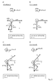
- Figure 3 shows schematically the working principle and the output values of the first acceleration sensor 13 and the gyroscope 14, mounted at the carrier 3.
- the first acceleration sensor 13 outputs at least two acceleration values, namely a first acceleration value a13x and a second acceleration value a13y, each representing accelerations in directions perpendicular to each other. Based on these two acceleration values a13x, a13y a resulting acceleration value a13 may be calculated.
- an accelerometer is a compact device designed to measure gravital or non-gravitational acceleration.
- the lateral accelerometer is not capable to measure the absolute orientation with the help of sensing the magnetic earth field.
- An angular accelerometer in particular a gyroscope, is a device that may use a freely-rotating disk called a rotor, mounted onto a spinning axis in the centre of a larger and more stable wheel. This device is only sensitive to angular accelerations and not sensitive for lateral accelerations and the magnetic earth field.
- the carrier 3 and the sensor 13 travel with constant speed along the first horizontal section 21, after the carrier has been accelerated by the drive means. Since gravity g in this stage is the only acceleration affecting the first acceleration sensor 13, the resulting acceleration value a13 represents the gravity which is indicated by the second acceleration value. The first acceleration value is 0.
- the resulting acceleration value a13 represents the gravity (here the amount of centrifugal force in the first transitional section 22 is neglected).
- an angle ⁇ * can be calculated using the function arctan(a13x/a13y).
- this calculated angle of orientation ⁇ * constitutes the correct angle of orientation ⁇ of the carrier 3 and the acceleration sensor 13 against the horizontal plane.
- the carrier 3 is located in the first end section and is at the moment accelerated by the drive motor.
- the first acceleration values a13x represents the acceleration, affected by the lateral acceleration by the drive motor.
- the second acceleration values a13y represent the gravity g.
- a defective, apparent inclination angle ⁇ * is calculated, which does not represent the true orientation ⁇ of the carrier 3 against the horizontal plane H.
- an angular acceleration value a14 ⁇ is measured by the gyroscope 14. As long as the carrier 3 is traveling in a section, where the inclination angle ⁇ is constant (sections 21, 23 and 25) the angular acceleration values a14 ⁇ is 0.
- the angular acceleration values differs from 0. But since in section 21 no angular acceleration a14 ⁇ is detected by the gyroscope 14, no change in the angular orientation ⁇ of the carrier is detected, even if the calculated angle ⁇ * or the relationship of the lateral acceleration values a13x, a13y fake the presence of an inclination.
- the acceleration values a13x, a13y are combined with the course of the angular acceleration value a14 ⁇ .
- the levelling control unit 12 determines an angle ⁇ between support 3 and carriage 4, based on which the levelling motor 11 is controlled.
- the first acceleration sensor may be adapted to measure a further third acceleration value, which is perpendicular to the first and second acceleration values a13x, a13y. This can improve the signal-quality of the first acceleration sensor.
- the additional, second acceleration sensor 15 on the support 4 is merely used to validate, that the support 4 or the chair 5 is in the desired orientation and to set a proper starting position in the stationary state.
- this stationary state merely gravity is affecting the second lateral acceleration sensor. Since the drive motor is not running, only small amount of noise is affecting the sensor.
- the second acceleration sensor is sufficiently adapted for delivering values for calculating the absolute orientation.
- the method for calculating is the same as described e.g. with reference to the first sensor in figure 3d .
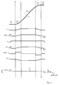
- FIG. 4 The course of the relevant values is drawn in figure 4 .
- a control loop diagram is drawn in figure 5 .
- a Kalman-filter 16 is shown which filters noise and faults and which delivers the pure orientation angle ⁇ of the carrier 3 against the horizontal level H based on the values obtained from the sensors mounted on the carrier 3.
- Levelling algorithm 17 calculates the desired angle ⁇ between the support 4 and the carriage 3 which is fed to the levelling motor 11.
- EP 2 216 284 B1 The advantage of using an acceleration sensor and gyroscope with respect to EP 2 216 284 B1 is explained with the help of value a13*x, drawn at the bottom of figure 4 .
- the levelling mechanism is operated based on an first acceleration sensor 13*, located at the support (also indicated for comparison in figure 1 ).
- the amplitude of the first acceleration value a13*x which is a relevant value for calculating the orientation of the acceleration sensor, has a main peak, when the carrier is accelerated in section 21.
- the amplitude is more or less constant, since the levelling mechanism continuously holds the support in a constant orientation.
- Figure 4 shows merely idealized courses of the different values.
- Figure 6 shows the first acceleration value a13x (according to the invention) and a13*x (according to the embodiment as in EP 2 216 284 B1 ) which include also noise.
- the amplitude of first acceleration value a13x according to the invention has a wide signal range S during travel along the path T, also resulting in a relatively high signal to noise ration SNR.
- the amplitude of first acceleration value a13*x according to prior art has a small signal range S during travel along the path T, resulting in a relatively low signal to noise ration SNR.
- the main relevant input value has a higher SNR compared to the prior art. Since in the prior art expensive sensors need to be used for compensating the pure SNR, in the inventive method this compensation is not necessary due to the improved SNR. So in the inventive method cheaper sensors can be used, which is the main improvement of the invention over the prior art. Also the system according to the prior art tends to produce oscillations, which is caused by the pure SNR; this problem is prevented by the inventive method.
- the first lateral acceleration sensor, the angular acceleration sensor and the second acceleration sensor are the only sensors, which are used for detecting the orientation or changes in the orientation of the carrier and support.
Landscapes
- Engineering & Computer Science (AREA)
- Mechanical Engineering (AREA)
- Transportation (AREA)
- Automation & Control Theory (AREA)
- Structural Engineering (AREA)
- Types And Forms Of Lifts (AREA)
Abstract
Method for controlling a lift (1), in particular a stairlift (1), the lift (1) comprises:
- a carrier (3), which is movable along a path of travel (T) defined by a rail (2), wherein the rail (2) is designed so that an inclination angle (α) of the path of travel is changing along the path of travel (T),
- a support (4), on which a user interface is mounted, in particular a chair (5), mounted on the support (4),
- a levelling mechanism (10), adapted to keep the support (4) in a constant orientation compared to a horizontal plane (H), when the orientation of the carrier (3) is changing due to the changing inclination angle (α),
- a first lateral acceleration sensor (13) for providing lateral acceleration values (a13x, a13y);
- an angular acceleration sensor (14) for providing an angular acceleration value (a14α);
comprising the following method steps:
measuring lateral acceleration values (a13x, a13y) of the carrier (3) by the first lateral acceleration sensor (13), which is mounted at the carrier (3);
measuring an angular acceleration value (a14α) of the carrier (3) by the angular acceleration sensor unit (14), which is mounted at the carrier (3);
combining the provided lateral accelerations values (a13x, a13y) and the angular acceleration value (a14α) to calculate an absolute orientation value (α) of the carrier (3);
based on the calculated absolute orientation value (α) calculating a control signal (18) of the levelling mechanism (10), adapted to keep the support (4) in a desired orientation (θ=0°; β=-α).
Description
- The invention refers to a method for controlling a lift, in particular a stairlift, and a lift, controlled by this method.
- Such lifts may be mounted at a stairway of residential homes. Often these stairs have a curved shape. Here, only lifts having a rail with changing inclination over the path of travel can be used. Therefore, a levelling mechanism is provided within the lift, to keep the seat of the chair of the stairlift in a horizontal position. Already small deviations of the stair from the horizontal orientation would cause a feeling of unsafety to a person using the stairlift.
- Within this application the terms carrier and support are used as follows:
- The term "carrier" is used for the unit of the lift, which is traveling along the rail and which orientation over the horizontal plane is changed with the inclination of the rail. The carrier connects the support with the rail.
- The term "support" is used for the unit of the lift, which is mounted via a levelling mechanism on the carrier. The levelling mechanism is adapted to keep the support in a constant orientation, even if the orientation of the carrier is changing. A transport platform, in particular a chair, may be attached to the support.
-
EP 2 216 284 B1 -
EP 1 037 846 B1 uses an orientation sensor mounted on the carrier to detect, if the carrier is traveling along a section of the rail with increasing or decreasing inclination. The kind of sensors is not described. - Absolute orientation sensors may use the magnetic earth field of registering a change in the orientation. These sensors are quite expensive if particular if these sensors are robust against electromagnetic perturbation and noise. Acceleration sensors are not capable of measuring an absolute orientation on their own since these sensors are not sensitive to the magnetic earth field, as explained below.
- The object of the invention is to provide an improved method for controlling a lift, in particular a stairlift, which is robust against perturbation, at the same time the possibility to use cheaper components is desirable. This object is solved by the method according to
claim 1 and the elevator according toclaim 5; preferred embodiments are disclosed in the subclaims and the description. - The lift, in particular a stairlift, comprises: a carrier, which is movable along a path of travel defined by a rail, wherein the rail is designed so that an inclination angle of the path of travel is changing along the path of travel; a support, on which a user interface is mounted, in particular a chair, mounted on the support; a levelling mechanism, adapted to keep the support in a constant orientation compared to a horizontal plane, when the orientation of the carrier is changing due to the changing inclination angle; a first lateral acceleration sensor for providing lateral acceleration values; an angular acceleration sensor for providing an (at least one) angular acceleration value.
- According to the invention the method comprises the following method steps: measuring lateral acceleration values of the carrier by the lateral acceleration sensor, which is mounted at the carrier; measuring an (at least one) angular acceleration value of the carrier by the angular acceleration sensor unit, which is mounted at the carrier; combining the provided lateral acceleration values and the angular acceleration value to calculate an absolute orientation value of the carrier; based on the calculated absolute orientation value calculating a control signal of the levelling mechanism, adapted to keep the support in a desired orientation.
- A main aspect of the invention is to use a lateral acceleration sensor and an angular acceleration sensor on the carrier for determining the orientation of the chair, which is the main input value for the levelling mechanism. Providing the sensors on the carrier leads to a better quality of controlling since the signal-to-noise-ratio of the sensor values can be improved compared to an arrangement which uses the sensors mounted at the support. This leads also to the advantage, that cheaper components can be used. Due to the better signal quality, the control loop can be designed more stable, thus oscillations can be prevented.
- In a preferred embodiment, by means of a second acceleration sensor, which is mounted at the support, the desired orientation is validated. The second acceleration sensor outputs second lateral acceleration values.
- The second acceleration values may be used for setting up the starting position in the stationary state. In the stationary state, the acceleration values are not influenced by lateral acceleration of the support, caused by the drive motor. So in the stationary state (speed of lift = 0) the second lateral acceleration sensor mounted at the support is useful to calculate the absolute orientation of the support, considering the direction of gravity. The possibility of calculating any orientation with the help of only of a lateral acceleration sensor (during a period without any other acceleration) is later described with reference to
figure 3b-3d , which is also applicable here. - So before starting the operation the support can be brought into the desired starting orientation by means of the second acceleration sensor, by turning the support into an orientation, in which the second acceleration sensor values indicated the desired orientation.
- In particular the first and/or the second acceleration sensor is merely sensitive to lateral acceleration, in particular not sensitive to magnetic earth field, and/or in particular not sensitive to angular acceleration.
- In particular the angular acceleration sensor is merely sensitive to angular acceleration, in particular not sensitive to lateral acceleration, and/or in particular not sensitive magnetic earth field.
- Such components can be purchased cost efficiently. Operated in the inventive method these cheap sensors can deliver sufficient values for improved levelling.
- The invention is further directed to a lift as described above. The lift comprise a control unit, adapted to control the levelling mechanism according to the method of any of the previous claims.
- The term "mounted at the carrier / support" means with respect to the acceleration sensor, that this sensor is connected to the carrier / support in such way, that the sensor is capable of measuring accelerations, which originally occur to the carrier / support. The sensor may be connected directly or indirectly to the carrier / support.
- The invention is illustrated in more detail below by means of drawings.
- Fig. 1
- shows a stairlift according to the invention, comprising a carrier 3 and a
chair support 4 withlevelling mechanism 10 for controlling the levelling of the support; - Fig. 2
- shows the path of the
rails 20, comprisingsections - Fig. 3
- shows schematically
sensors - Fig. 4
- shows the course of relevant values during operation;
- Fig. 5
- shows a control loop of the levelling mechanism;
- Fig. 6
- shows selected values from
figure 4 comprising noise. -
Figures 1 and 2 show astairlift 1 mounted at astairway 6 of residential homes. Arail 20 follows the course of thestairway 6 and defines a path of travel T. A carrier 3 is attached to therail 2 and is driveable along the path of travel by a non shown drive motor. Thereby an orientation angle α of the carrier 3 against a horizontal plane H follows the inclination of therail 2. - A
support 4 is mounted on the carrier 3. Achair 5 is supported by thesupport 4. Alevelling mechanism 10 is provided, to keep thesupport 4 in a constant orientation and to keep theseat 5 in a horizontal orientation. Thelevelling mechanism 10 therefore comprises a levellingmotor 11. An angle θ between theseat 5 and the horizontal plane H should be 0° during operation. - The
levelling mechanism 10 comprises a levellingmotor 11, capable of rotating thesupport 4 against the carrier 3. The levelling mechanism comprises further a number of sensors, namely afirst acceleration sensor 13 mounted at the carriage 3, agyroscope 14 mounted at the carriage 3 and asecond acceleration sensor 15 mounted at thesupport 4. - The
rail 2 comprises sections 21-25 of different inclination. In afirst end section 21 and asecond end section 25 the inclination angle of the rail is in thiscase 0°. Any other angle between 0° and 90° is possible. In acentral section 23 the inclination angle α is constant at about 45° or any other angle, which is mostly pre-set by the inclination of the stairway. In a firsttransitional section 22 between thefirst end section 21 and thecentral section 23 the inclination angle α is increasing, in a secondtransitional section 24 between thecentral section 23 and thesecond end section 25 the inclination is decreasing. If the carrier 3 is traveling along the rail, an orientation α of the carrier 3 against the horizontal plane H is at first 0° (first end sections 21), then increasing (first transitional section 22), then about 45° or any other constant value above 0° (central section 23), then decreasing (second transitional section 24), and finally 0° (second end section). This course of the angle α is drawn infigure 4 . -
Figure 3 shows schematically the working principle and the output values of thefirst acceleration sensor 13 and thegyroscope 14, mounted at the carrier 3. Thefirst acceleration sensor 13 outputs at least two acceleration values, namely a first acceleration value a13x and a second acceleration value a13y, each representing accelerations in directions perpendicular to each other. Based on these two acceleration values a13x, a13y a resulting acceleration value a13 may be calculated. - In this context an accelerometer is a compact device designed to measure gravital or non-gravitational acceleration. The lateral accelerometer is not capable to measure the absolute orientation with the help of sensing the magnetic earth field. An angular accelerometer, in particular a gyroscope, is a device that may use a freely-rotating disk called a rotor, mounted onto a spinning axis in the centre of a larger and more stable wheel. This device is only sensitive to angular accelerations and not sensitive for lateral accelerations and the magnetic earth field.
- In
figure 3b , the carrier 3 and thesensor 13 travel with constant speed along the firsthorizontal section 21, after the carrier has been accelerated by the drive means. Since gravity g in this stage is the only acceleration affecting thefirst acceleration sensor 13, the resulting acceleration value a13 represents the gravity which is indicated by the second acceleration value. The first acceleration value is 0. - In
figure 3c the angle α of orientation of the carrier 3 and thefirst acceleration sensor 13 against the horizontal direction H is greater than 0°, during travel in the firsttransitional section 22 with a constant speed. - Since gravity g is the only acceleration, affecting the
fist acceleration sensor 13, the resulting acceleration value a13 represents the gravity (here the amount of centrifugal force in the firsttransitional section 22 is neglected). From the first acceleration value a13x and the second acceleration value a13y, an angle α* can be calculated using the function arctan(a13x/a13y). Here this calculated angle of orientation α* constitutes the correct angle of orientation α of the carrier 3 and theacceleration sensor 13 against the horizontal plane. - Mainly same applies when the carrier is driving through
central section 23 with constant speed, as shown infigure 3d . The difference tofigure 3c is merely, that the angular acceleration a14α is 0 and the orientation angle α is increased. - In
figure 3a , the carrier 3 is located in the first end section and is at the moment accelerated by the drive motor. Here, the first acceleration values a13x represents the acceleration, affected by the lateral acceleration by the drive motor. Additionally the second acceleration values a13y represent the gravity g. Using again the arctan-function, here a defective, apparent inclination angle α* is calculated, which does not represent the true orientation α of the carrier 3 against the horizontal plane H. To ensure proper calculation of the orientation angle α, additionally an angular acceleration value a14α is measured by thegyroscope 14. As long as the carrier 3 is traveling in a section, where the inclination angle α is constant (sections transitional sections rail 2 is increasing/decreasing, the angular acceleration values differs from 0. But since insection 21 no angular acceleration a14α is detected by thegyroscope 14, no change in the angular orientation α of the carrier is detected, even if the calculated angle α* or the relationship of the lateral acceleration values a13x, a13y fake the presence of an inclination. - Thus, to calculate a proper angle of orientation α, the acceleration values a13x, a13y are combined with the course of the angular acceleration value a14α. The levelling
control unit 12 then determines an angle β between support 3 andcarriage 4, based on which the levellingmotor 11 is controlled. - The first acceleration sensor may be adapted to measure a further third acceleration value, which is perpendicular to the first and second acceleration values a13x, a13y. This can improve the signal-quality of the first acceleration sensor.
- The additional,
second acceleration sensor 15 on thesupport 4 is merely used to validate, that thesupport 4 or thechair 5 is in the desired orientation and to set a proper starting position in the stationary state. In this stationary state merely gravity is affecting the second lateral acceleration sensor. Since the drive motor is not running, only small amount of noise is affecting the sensor. In this state, the second acceleration sensor is sufficiently adapted for delivering values for calculating the absolute orientation. The method for calculating is the same as described e.g. with reference to the first sensor infigure 3d . - The course of the relevant values is drawn in
figure 4 . A control loop diagram is drawn infigure 5 . Here additionally a Kalman-filter 16 is shown which filters noise and faults and which delivers the pure orientation angle α of the carrier 3 against the horizontal level H based on the values obtained from the sensors mounted on the carrier 3. Levellingalgorithm 17 calculates the desired angle β between thesupport 4 and the carriage 3 which is fed to the levellingmotor 11. - The advantage of using an acceleration sensor and gyroscope with respect to
EP 2 216 284 B1figure 4 . According toEP 2 216 284 B1first acceleration sensor 13*, located at the support (also indicated for comparison infigure 1 ). Infigure 4 the amplitude of the first acceleration value a13*x, which is a relevant value for calculating the orientation of the acceleration sensor, has a main peak, when the carrier is accelerated insection 21. During the further operation, the amplitude is more or less constant, since the levelling mechanism continuously holds the support in a constant orientation. If there are deviations from the horizontal orientation (here indicated with D) the levelling mechanism quickly tries to bring the support back into the horizontal orientation. Thus, an idealized course of the first acceleration value a13*x, if sensor is mounted on thesupport 4, would always be a constant value (with exception during the phase of lateral acceleration). Merely from small deviations from desired orientation of θ=0° the control loop is prompted to correct the orientation. -
Figure 4 shows merely idealized courses of the different values.Figure 6 shows the first acceleration value a13x (according to the invention) and a13*x (according to the embodiment as inEP 2 216 284 B1 - According to the inventive arrangement of the acceleration sensor for controlling the levelling mechanism, the main relevant input value has a higher SNR compared to the prior art. Since in the prior art expensive sensors need to be used for compensating the pure SNR, in the inventive method this compensation is not necessary due to the improved SNR. So in the inventive method cheaper sensors can be used, which is the main improvement of the invention over the prior art. Also the system according to the prior art tends to produce oscillations, which is caused by the pure SNR; this problem is prevented by the inventive method.
- In particular, the first lateral acceleration sensor, the angular acceleration sensor and the second acceleration sensor are the only sensors, which are used for detecting the orientation or changes in the orientation of the carrier and support.
-
- 1
- stairlift
- 2
- rail
- 3
- carriage
- 4
- support
- 5
- chair
- 6
- stairway
- 10
- levelling mechanism
- 11
- levelling drive
- 12
- levelling control unit
- 13
- first accelerometer at carriage
- 13*
- first accelerometer at carriage (as in prior art)
- 14
- gyroscope at carriage
- 15
- second accelerometer at support
- 16
- Kalman-filter
- 17
- levelling algorithm
- 18
- control signal for levelling motor
- 20
- path of travel
- 21
- first end section
- 22
- first transitional section
- 23
- central section
- 24
- second transitional section
- 25
- second end section
- α
- (true) orientation angle of carriage against horizontal plane
- β
- angle between support and carriage
- θ
- angle between support and horizontal plane
- α*
- (defective) orientation angle calculated by lateral acceleration values only
- T
- transport direction
- H
- horizontal plane
- g
- gravity
- T
- transport direction
- S
- signal amplitude
- N
- noise amplitude
- SNR
- signal-to-noise-ratio
- a13x
- lateral acceleration value in x-direction of
first acceleration sensor 13 - a13y
- lateral acceleration value in y-direction of
first acceleration sensor 13 - a13*x
- lateral acceleration value in x-direction of
first acceleration sensor 13*, as installed in the prior art - a13
- lateral resulting acceleration vector
- a14α
- angular acceleration value of gyroscope at carriage
Claims (6)
- Method for controlling a lift (1), in particular a stairlift (1),
the lift (1) comprises:- a carrier (3), which is movable along a path of travel (20) defined by a rail (2), wherein the rail (2) is designed so that an inclination angle (α) of the path of travel is changing along the path of travel (2),- a support (4), on which a user interface is mounted, in particular a chair (5), mounted on the support (4),- a levelling mechanism (11), adapted to keep the support (4) in a constant orientation compared to a horizontal plane (H), when the orientation of the carrier (3) is changing due to the changing inclination angle (α),- a first lateral acceleration sensor (13) for providing lateral acceleration values (a13x, a13y);- an angular acceleration sensor (14) for providing an angular acceleration value (a14α);characterized by the following method steps:measuring lateral acceleration values (a13x, a13y) of the carrier (3) by the first lateral acceleration sensor (13), which is mounted at the carrier (3);measuring an angular acceleration value (a14α) of the carrier (3) by the angular acceleration sensor unit (14), which is mounted at the carrier (3);combining the provided lateral accelerations values (a13x, a13y) and the angular acceleration value (a14α) to calculate an absolute orientation value (α) of the carrier (4);based on the calculated absolute orientation value (α) calculating a control signal (18) of the levelling mechanism (10), adapted to keep the support (4) in a desired orientation (θ=0°; β=-α). - Method according to the previous claim,
characterized in
that by means of a second acceleration sensor (15) mounted on the support (4) the desired orientation (θ=0°) is validated. - Method according to any of the previous claims,
characterized in
that by means of a second acceleration sensor (15) the orientation of the support (4) is set to a starting position in the stationary state. - Method according the previous claim,
characterized in
that the first acceleration sensor (13) is merely sensitive to lateral acceleration in particular not sensitive to magnetic earth field, and that the angular acceleration sensor is merely sensitive to angular acceleration (a14α), in particular not sensitive to lateral acceleration. - Lift (1), comprising- a carrier (3), which is movable along a path of travel (20) defined by a rail (2), wherein the rail (2) is designed so that an inclination angle ( ) of the path of travel is changing along the path of travel (2),- a support (4), on which a user interface is mounted, in particular a chair (5), mounted on the support (4),- a levelling mechanism (11), adapted to keep the support (4) in a constant orientation compared to a horizontal plane (H), when the orientation of the carrier (3) is changing due to the changing inclination angle (α),- a first lateral acceleration sensor (13) for providing lateral acceleration values (a13x, a13y);- an angular acceleration sensor (14) for providing an angular acceleration value (a14α);- a control unit (12), adapted to control the levelling mechanism (11) according to the method of any of the previous claims.
- Elevator (1), according the previous claim,
characterized by
a second acceleration sensor (15), mounted at the support (4).
Priority Applications (1)
| Application Number | Priority Date | Filing Date | Title |
|---|---|---|---|
| EP16154071.1A EP3202699B1 (en) | 2016-02-03 | 2016-02-03 | Method for controlling a stairlift |
Applications Claiming Priority (1)
| Application Number | Priority Date | Filing Date | Title |
|---|---|---|---|
| EP16154071.1A EP3202699B1 (en) | 2016-02-03 | 2016-02-03 | Method for controlling a stairlift |
Publications (2)
| Publication Number | Publication Date |
|---|---|
| EP3202699A1 true EP3202699A1 (en) | 2017-08-09 |
| EP3202699B1 EP3202699B1 (en) | 2022-08-10 |
Family
ID=55304888
Family Applications (1)
| Application Number | Title | Priority Date | Filing Date |
|---|---|---|---|
| EP16154071.1A Active EP3202699B1 (en) | 2016-02-03 | 2016-02-03 | Method for controlling a stairlift |
Country Status (1)
| Country | Link |
|---|---|
| EP (1) | EP3202699B1 (en) |
Cited By (2)
| Publication number | Priority date | Publication date | Assignee | Title |
|---|---|---|---|---|
| GB2566333A (en) * | 2017-09-12 | 2019-03-13 | Stannah Stairlifts Ltd | Improvements in or relating to stairlifts |
| US20220315386A1 (en) * | 2019-05-31 | 2022-10-06 | Bruno Independent Living Aids, Inc. | Multi-function stairlift connectivity system |
Citations (4)
| Publication number | Priority date | Publication date | Assignee | Title |
|---|---|---|---|---|
| GB2358389A (en) * | 1999-12-23 | 2001-07-25 | Brooks Stairlifts Ltd | Stairlift seat orientation controller |
| EP1037846B1 (en) | 1997-12-11 | 2002-05-08 | Thyssen De Reus B.V. | Stairlift |
| EP2216284B1 (en) | 2009-02-06 | 2012-06-20 | Otto Ooms B.V. | Apparatus for transporting a load from a first to a second level, in particular a stairlift |
| GB2526621A (en) * | 2014-05-30 | 2015-12-02 | Stannah Stairlifts Ltd | Improvements in or relating to stairlifts |
-
2016
- 2016-02-03 EP EP16154071.1A patent/EP3202699B1/en active Active
Patent Citations (4)
| Publication number | Priority date | Publication date | Assignee | Title |
|---|---|---|---|---|
| EP1037846B1 (en) | 1997-12-11 | 2002-05-08 | Thyssen De Reus B.V. | Stairlift |
| GB2358389A (en) * | 1999-12-23 | 2001-07-25 | Brooks Stairlifts Ltd | Stairlift seat orientation controller |
| EP2216284B1 (en) | 2009-02-06 | 2012-06-20 | Otto Ooms B.V. | Apparatus for transporting a load from a first to a second level, in particular a stairlift |
| GB2526621A (en) * | 2014-05-30 | 2015-12-02 | Stannah Stairlifts Ltd | Improvements in or relating to stairlifts |
Cited By (5)
| Publication number | Priority date | Publication date | Assignee | Title |
|---|---|---|---|---|
| GB2566333A (en) * | 2017-09-12 | 2019-03-13 | Stannah Stairlifts Ltd | Improvements in or relating to stairlifts |
| WO2019053410A1 (en) * | 2017-09-12 | 2019-03-21 | Stannah Stairlifts Ltd | Improvements in or relating to stairlifts |
| GB2566333B (en) * | 2017-09-12 | 2022-10-12 | Stannah Stairlifts Ltd | Improvements in or relating to stairlifts |
| US20220315386A1 (en) * | 2019-05-31 | 2022-10-06 | Bruno Independent Living Aids, Inc. | Multi-function stairlift connectivity system |
| US12208993B2 (en) * | 2019-05-31 | 2025-01-28 | Bruno Independent Living Aids, Inc. | Multi-function stairlift connectivity system |
Also Published As
| Publication number | Publication date |
|---|---|
| EP3202699B1 (en) | 2022-08-10 |
Similar Documents
| Publication | Publication Date | Title |
|---|---|---|
| US8589059B2 (en) | Vehicle with inclination estimation | |
| CN107428507B (en) | Stair lift speed control | |
| EP2771270B1 (en) | Stairlift system | |
| JPH11123994A (en) | Apparatus and method for controlling start-up device of automobile accident prevention device | |
| CN104718148A (en) | Safety device of an elevator system | |
| CA2540431A1 (en) | Elevator apparatus | |
| EP3202699B1 (en) | Method for controlling a stairlift | |
| WO2018155489A1 (en) | Vehicle control device, vehicle control method, and program | |
| JP2008044680A (en) | Control device of elevator | |
| EP3757049B1 (en) | Building drift determination based on elevator roping position | |
| KR102135192B1 (en) | Elevator control device and control method | |
| WO2019053410A1 (en) | Improvements in or relating to stairlifts | |
| GB2526621A (en) | Improvements in or relating to stairlifts | |
| JPH10139371A (en) | Trolley camera position detecting device | |
| WO2020079395A2 (en) | Stairlift and method of operating a stairlift | |
| JP6911284B2 (en) | Rotational synchronous phase detector and magnetic bearing device | |
| JPWO2020115860A1 (en) | Elevator tension measuring device | |
| GB2527410A (en) | Lift system | |
| JP6223636B2 (en) | Elevator moving distance measuring device and elevator moving distance measuring method | |
| US20120065812A1 (en) | Vehicle controller | |
| JP2005298171A (en) | Elevator abnormality detection device | |
| JPH09272605A (en) | Running controller for stacker crane | |
| CN109956375A (en) | Elevator control device and elevator control method | |
| JP6325924B2 (en) | Elevator control device | |
| JP6187310B2 (en) | Inverted moving body |
Legal Events
| Date | Code | Title | Description |
|---|---|---|---|
| PUAI | Public reference made under article 153(3) epc to a published international application that has entered the european phase |
Free format text: ORIGINAL CODE: 0009012 |
|
| STAA | Information on the status of an ep patent application or granted ep patent |
Free format text: STATUS: THE APPLICATION HAS BEEN PUBLISHED |
|
| AK | Designated contracting states |
Kind code of ref document: A1 Designated state(s): AL AT BE BG CH CY CZ DE DK EE ES FI FR GB GR HR HU IE IS IT LI LT LU LV MC MK MT NL NO PL PT RO RS SE SI SK SM TR |
|
| AX | Request for extension of the european patent |
Extension state: BA ME |
|
| RAP1 | Party data changed (applicant data changed or rights of an application transferred) |
Owner name: THYSSENKRUPP ACCESSIBILITY B.V. Owner name: THYSSENKRUPP AG |
|
| STAA | Information on the status of an ep patent application or granted ep patent |
Free format text: STATUS: REQUEST FOR EXAMINATION WAS MADE |
|
| 17P | Request for examination filed |
Effective date: 20180208 |
|
| RBV | Designated contracting states (corrected) |
Designated state(s): AL AT BE BG CH CY CZ DE DK EE ES FI FR GB GR HR HU IE IS IT LI LT LU LV MC MK MT NL NO PL PT RO RS SE SI SK SM TR |
|
| RAP1 | Party data changed (applicant data changed or rights of an application transferred) |
Owner name: THYSSENKRUPP STAIRLIFTS B.V. Owner name: THYSSENKRUPP AG |
|
| RAP1 | Party data changed (applicant data changed or rights of an application transferred) |
Owner name: THYSSENKRUPP STAIRLIFTS B.V. |
|
| STAA | Information on the status of an ep patent application or granted ep patent |
Free format text: STATUS: EXAMINATION IS IN PROGRESS |
|
| 17Q | First examination report despatched |
Effective date: 20210326 |
|
| RAP3 | Party data changed (applicant data changed or rights of an application transferred) |
Owner name: TK HOME SOLUTIONS B.V. |
|
| GRAP | Despatch of communication of intention to grant a patent |
Free format text: ORIGINAL CODE: EPIDOSNIGR1 |
|
| STAA | Information on the status of an ep patent application or granted ep patent |
Free format text: STATUS: GRANT OF PATENT IS INTENDED |
|
| INTG | Intention to grant announced |
Effective date: 20220405 |
|
| GRAS | Grant fee paid |
Free format text: ORIGINAL CODE: EPIDOSNIGR3 |
|
| GRAA | (expected) grant |
Free format text: ORIGINAL CODE: 0009210 |
|
| STAA | Information on the status of an ep patent application or granted ep patent |
Free format text: STATUS: THE PATENT HAS BEEN GRANTED |
|
| AK | Designated contracting states |
Kind code of ref document: B1 Designated state(s): AL AT BE BG CH CY CZ DE DK EE ES FI FR GB GR HR HU IE IS IT LI LT LU LV MC MK MT NL NO PL PT RO RS SE SI SK SM TR |
|
| REG | Reference to a national code |
Ref country code: AT Ref legal event code: REF Ref document number: 1510416 Country of ref document: AT Kind code of ref document: T Effective date: 20220815 Ref country code: CH Ref legal event code: EP |
|
| REG | Reference to a national code |
Ref country code: IE Ref legal event code: FG4D |
|
| REG | Reference to a national code |
Ref country code: DE Ref legal event code: R096 Ref document number: 602016074098 Country of ref document: DE |
|
| REG | Reference to a national code |
Ref country code: NL Ref legal event code: FP |
|
| REG | Reference to a national code |
Ref country code: LT Ref legal event code: MG9D |
|
| PG25 | Lapsed in a contracting state [announced via postgrant information from national office to epo] |
Ref country code: SE Free format text: LAPSE BECAUSE OF FAILURE TO SUBMIT A TRANSLATION OF THE DESCRIPTION OR TO PAY THE FEE WITHIN THE PRESCRIBED TIME-LIMIT Effective date: 20220810 Ref country code: RS Free format text: LAPSE BECAUSE OF FAILURE TO SUBMIT A TRANSLATION OF THE DESCRIPTION OR TO PAY THE FEE WITHIN THE PRESCRIBED TIME-LIMIT Effective date: 20220810 Ref country code: PT Free format text: LAPSE BECAUSE OF FAILURE TO SUBMIT A TRANSLATION OF THE DESCRIPTION OR TO PAY THE FEE WITHIN THE PRESCRIBED TIME-LIMIT Effective date: 20221212 Ref country code: NO Free format text: LAPSE BECAUSE OF FAILURE TO SUBMIT A TRANSLATION OF THE DESCRIPTION OR TO PAY THE FEE WITHIN THE PRESCRIBED TIME-LIMIT Effective date: 20221110 Ref country code: LV Free format text: LAPSE BECAUSE OF FAILURE TO SUBMIT A TRANSLATION OF THE DESCRIPTION OR TO PAY THE FEE WITHIN THE PRESCRIBED TIME-LIMIT Effective date: 20220810 Ref country code: LT Free format text: LAPSE BECAUSE OF FAILURE TO SUBMIT A TRANSLATION OF THE DESCRIPTION OR TO PAY THE FEE WITHIN THE PRESCRIBED TIME-LIMIT Effective date: 20220810 Ref country code: FI Free format text: LAPSE BECAUSE OF FAILURE TO SUBMIT A TRANSLATION OF THE DESCRIPTION OR TO PAY THE FEE WITHIN THE PRESCRIBED TIME-LIMIT Effective date: 20220810 Ref country code: ES Free format text: LAPSE BECAUSE OF FAILURE TO SUBMIT A TRANSLATION OF THE DESCRIPTION OR TO PAY THE FEE WITHIN THE PRESCRIBED TIME-LIMIT Effective date: 20220810 |
|
| REG | Reference to a national code |
Ref country code: AT Ref legal event code: MK05 Ref document number: 1510416 Country of ref document: AT Kind code of ref document: T Effective date: 20220810 |
|
| PG25 | Lapsed in a contracting state [announced via postgrant information from national office to epo] |
Ref country code: PL Free format text: LAPSE BECAUSE OF FAILURE TO SUBMIT A TRANSLATION OF THE DESCRIPTION OR TO PAY THE FEE WITHIN THE PRESCRIBED TIME-LIMIT Effective date: 20220810 Ref country code: IS Free format text: LAPSE BECAUSE OF FAILURE TO SUBMIT A TRANSLATION OF THE DESCRIPTION OR TO PAY THE FEE WITHIN THE PRESCRIBED TIME-LIMIT Effective date: 20221210 Ref country code: HR Free format text: LAPSE BECAUSE OF FAILURE TO SUBMIT A TRANSLATION OF THE DESCRIPTION OR TO PAY THE FEE WITHIN THE PRESCRIBED TIME-LIMIT Effective date: 20220810 Ref country code: GR Free format text: LAPSE BECAUSE OF FAILURE TO SUBMIT A TRANSLATION OF THE DESCRIPTION OR TO PAY THE FEE WITHIN THE PRESCRIBED TIME-LIMIT Effective date: 20221111 |
|
| PG25 | Lapsed in a contracting state [announced via postgrant information from national office to epo] |
Ref country code: SM Free format text: LAPSE BECAUSE OF FAILURE TO SUBMIT A TRANSLATION OF THE DESCRIPTION OR TO PAY THE FEE WITHIN THE PRESCRIBED TIME-LIMIT Effective date: 20220810 Ref country code: RO Free format text: LAPSE BECAUSE OF FAILURE TO SUBMIT A TRANSLATION OF THE DESCRIPTION OR TO PAY THE FEE WITHIN THE PRESCRIBED TIME-LIMIT Effective date: 20220810 Ref country code: DK Free format text: LAPSE BECAUSE OF FAILURE TO SUBMIT A TRANSLATION OF THE DESCRIPTION OR TO PAY THE FEE WITHIN THE PRESCRIBED TIME-LIMIT Effective date: 20220810 Ref country code: CZ Free format text: LAPSE BECAUSE OF FAILURE TO SUBMIT A TRANSLATION OF THE DESCRIPTION OR TO PAY THE FEE WITHIN THE PRESCRIBED TIME-LIMIT Effective date: 20220810 Ref country code: AT Free format text: LAPSE BECAUSE OF FAILURE TO SUBMIT A TRANSLATION OF THE DESCRIPTION OR TO PAY THE FEE WITHIN THE PRESCRIBED TIME-LIMIT Effective date: 20220810 |
|
| REG | Reference to a national code |
Ref country code: DE Ref legal event code: R097 Ref document number: 602016074098 Country of ref document: DE |
|
| PG25 | Lapsed in a contracting state [announced via postgrant information from national office to epo] |
Ref country code: SK Free format text: LAPSE BECAUSE OF FAILURE TO SUBMIT A TRANSLATION OF THE DESCRIPTION OR TO PAY THE FEE WITHIN THE PRESCRIBED TIME-LIMIT Effective date: 20220810 Ref country code: EE Free format text: LAPSE BECAUSE OF FAILURE TO SUBMIT A TRANSLATION OF THE DESCRIPTION OR TO PAY THE FEE WITHIN THE PRESCRIBED TIME-LIMIT Effective date: 20220810 |
|
| PLBE | No opposition filed within time limit |
Free format text: ORIGINAL CODE: 0009261 |
|
| STAA | Information on the status of an ep patent application or granted ep patent |
Free format text: STATUS: NO OPPOSITION FILED WITHIN TIME LIMIT |
|
| PG25 | Lapsed in a contracting state [announced via postgrant information from national office to epo] |
Ref country code: AL Free format text: LAPSE BECAUSE OF FAILURE TO SUBMIT A TRANSLATION OF THE DESCRIPTION OR TO PAY THE FEE WITHIN THE PRESCRIBED TIME-LIMIT Effective date: 20220810 |
|
| P01 | Opt-out of the competence of the unified patent court (upc) registered |
Effective date: 20230526 |
|
| 26N | No opposition filed |
Effective date: 20230511 |
|
| PG25 | Lapsed in a contracting state [announced via postgrant information from national office to epo] |
Ref country code: SI Free format text: LAPSE BECAUSE OF FAILURE TO SUBMIT A TRANSLATION OF THE DESCRIPTION OR TO PAY THE FEE WITHIN THE PRESCRIBED TIME-LIMIT Effective date: 20220810 |
|
| PG25 | Lapsed in a contracting state [announced via postgrant information from national office to epo] |
Ref country code: MC Free format text: LAPSE BECAUSE OF FAILURE TO SUBMIT A TRANSLATION OF THE DESCRIPTION OR TO PAY THE FEE WITHIN THE PRESCRIBED TIME-LIMIT Effective date: 20220810 |
|
| REG | Reference to a national code |
Ref country code: CH Ref legal event code: PL |
|
| PG25 | Lapsed in a contracting state [announced via postgrant information from national office to epo] |
Ref country code: LU Free format text: LAPSE BECAUSE OF NON-PAYMENT OF DUE FEES Effective date: 20230203 Ref country code: LI Free format text: LAPSE BECAUSE OF NON-PAYMENT OF DUE FEES Effective date: 20230228 Ref country code: CH Free format text: LAPSE BECAUSE OF NON-PAYMENT OF DUE FEES Effective date: 20230228 |
|
| REG | Reference to a national code |
Ref country code: IE Ref legal event code: MM4A |
|
| PG25 | Lapsed in a contracting state [announced via postgrant information from national office to epo] |
Ref country code: IE Free format text: LAPSE BECAUSE OF NON-PAYMENT OF DUE FEES Effective date: 20230203 |
|
| PG25 | Lapsed in a contracting state [announced via postgrant information from national office to epo] |
Ref country code: IT Free format text: LAPSE BECAUSE OF FAILURE TO SUBMIT A TRANSLATION OF THE DESCRIPTION OR TO PAY THE FEE WITHIN THE PRESCRIBED TIME-LIMIT Effective date: 20220810 |
|
| PG25 | Lapsed in a contracting state [announced via postgrant information from national office to epo] |
Ref country code: BG Free format text: LAPSE BECAUSE OF FAILURE TO SUBMIT A TRANSLATION OF THE DESCRIPTION OR TO PAY THE FEE WITHIN THE PRESCRIBED TIME-LIMIT Effective date: 20220810 |
|
| PG25 | Lapsed in a contracting state [announced via postgrant information from national office to epo] |
Ref country code: BG Free format text: LAPSE BECAUSE OF FAILURE TO SUBMIT A TRANSLATION OF THE DESCRIPTION OR TO PAY THE FEE WITHIN THE PRESCRIBED TIME-LIMIT Effective date: 20220810 |
|
| PG25 | Lapsed in a contracting state [announced via postgrant information from national office to epo] |
Ref country code: CY Free format text: LAPSE BECAUSE OF FAILURE TO SUBMIT A TRANSLATION OF THE DESCRIPTION OR TO PAY THE FEE WITHIN THE PRESCRIBED TIME-LIMIT; INVALID AB INITIO Effective date: 20160203 |
|
| PG25 | Lapsed in a contracting state [announced via postgrant information from national office to epo] |
Ref country code: HU Free format text: LAPSE BECAUSE OF FAILURE TO SUBMIT A TRANSLATION OF THE DESCRIPTION OR TO PAY THE FEE WITHIN THE PRESCRIBED TIME-LIMIT; INVALID AB INITIO Effective date: 20160203 |
|
| PG25 | Lapsed in a contracting state [announced via postgrant information from national office to epo] |
Ref country code: TR Free format text: LAPSE BECAUSE OF FAILURE TO SUBMIT A TRANSLATION OF THE DESCRIPTION OR TO PAY THE FEE WITHIN THE PRESCRIBED TIME-LIMIT Effective date: 20220810 |
|
| PGFP | Annual fee paid to national office [announced via postgrant information from national office to epo] |
Ref country code: NL Payment date: 20260218 Year of fee payment: 11 |
|
| PGFP | Annual fee paid to national office [announced via postgrant information from national office to epo] |
Ref country code: GB Payment date: 20260219 Year of fee payment: 11 |
|
| PGFP | Annual fee paid to national office [announced via postgrant information from national office to epo] |
Ref country code: DE Payment date: 20260218 Year of fee payment: 11 |
|
| PGFP | Annual fee paid to national office [announced via postgrant information from national office to epo] |
Ref country code: BE Payment date: 20260218 Year of fee payment: 11 |
|
| PGFP | Annual fee paid to national office [announced via postgrant information from national office to epo] |
Ref country code: FR Payment date: 20260218 Year of fee payment: 11 |