EP3202648A1 - Track vehicle with fluidly damped idler recoil system - Google Patents
Track vehicle with fluidly damped idler recoil system Download PDFInfo
- Publication number
- EP3202648A1 EP3202648A1 EP17154109.7A EP17154109A EP3202648A1 EP 3202648 A1 EP3202648 A1 EP 3202648A1 EP 17154109 A EP17154109 A EP 17154109A EP 3202648 A1 EP3202648 A1 EP 3202648A1
- Authority
- EP
- European Patent Office
- Prior art keywords
- fluid
- track
- recoiler
- circuit
- tensioner
- Prior art date
- Legal status (The legal status is an assumption and is not a legal conclusion. Google has not performed a legal analysis and makes no representation as to the accuracy of the status listed.)
- Granted
Links
Images


Classifications
-
- B—PERFORMING OPERATIONS; TRANSPORTING
- B62—LAND VEHICLES FOR TRAVELLING OTHERWISE THAN ON RAILS
- B62D—MOTOR VEHICLES; TRAILERS
- B62D55/00—Endless track vehicles
- B62D55/08—Endless track units; Parts thereof
- B62D55/30—Track-tensioning means
-
- B—PERFORMING OPERATIONS; TRANSPORTING
- B62—LAND VEHICLES FOR TRAVELLING OTHERWISE THAN ON RAILS
- B62D—MOTOR VEHICLES; TRAILERS
- B62D55/00—Endless track vehicles
- B62D55/06—Endless track vehicles with tracks without ground wheels
-
- B—PERFORMING OPERATIONS; TRANSPORTING
- B62—LAND VEHICLES FOR TRAVELLING OTHERWISE THAN ON RAILS
- B62D—MOTOR VEHICLES; TRAILERS
- B62D55/00—Endless track vehicles
- B62D55/08—Endless track units; Parts thereof
- B62D55/14—Arrangement, location, or adaptation of rollers
-
- E—FIXED CONSTRUCTIONS
- E02—HYDRAULIC ENGINEERING; FOUNDATIONS; SOIL SHIFTING
- E02F—DREDGING; SOIL-SHIFTING
- E02F3/00—Dredgers; Soil-shifting machines
- E02F3/04—Dredgers; Soil-shifting machines mechanically-driven
- E02F3/76—Graders, bulldozers, or the like with scraper plates or ploughshare-like elements; Levelling scarifying devices
- E02F3/7609—Scraper blade mounted forwardly of the tractor on a pair of pivoting arms which are linked to the sides of the tractor, e.g. bulldozers
Definitions
- the present invention relates to track vehicles, and, more particularly, to track vehicles with idler recoil systems.
- a tracked drive is a system of vehicle propulsion in which a continuous band of treads, which can be referred to as a track, is driven by two or more wheels.
- This band is typically made of modular steel plates, in the case of military vehicles and construction equipment, or rubber reinforced with steel wires in the case of agricultural or lighter construction vehicles.
- the large surface area of the track distributes the weight of the vehicle better than wheels on an equivalent vehicle, enabling a continuous tracked vehicle to traverse soft ground with superior traction and less likelihood of becoming stuck.
- a driving wheel such as a sprocket
- a driving wheel such as a sprocket
- the chain pins can press into the space between the sprocket teeth and the sprocket teeth can press into the space between chain pins as the sprocket rotates, allowing rotation of the sprocket to also rotate the track.
- idler wheels push on and engage the track at a front and rear of the track.
- a tensioner can be provided that will initially force the idler wheels into the track. This allows the track to maintain a desired front-to-rear length as the track rotates about the sprocket without slacking.
- the recoil systems can include, for example, a spring that compresses upon the front-to-rear length of the track being decreased, with the stored force/energy then pushing the idler wheels back into their original operating position upon the track becoming slacked.
- the present invention provides a track vehicle with a tensioner and a recoiler coupled to a fluid damper which can allow substantially unrestricted forcing on the recoiler by an idler wheel and reduce the noise and shock created when the recoiler pushes the idler wheel back into its original operating position.
- the invention in one form is directed to a track vehicle including: a track frame; a driving wheel carried by the track frame and configured to rotate; a track rotatably engaged with the driving wheel; at least one idler wheel engaged with the track; a tensioner coupled to the at least one idler wheel and configured to force the at least one idler wheel into engagement with the track; a recoiler coupled to the tensioner; and a fluid damper attached to the track frame and coupled to the tensioner and the recoiler.
- the fluid damper includes: a fluid chamber having a first port and a second port; a piston coupled to at least one of the tensioner and the recoiler within the fluid chamber; and a restriction circuit fluidly connected to the first port and the second port and configured to form a closed fluid circuit, the restriction circuit configured to permit a substantially unrestricted fluid flow through the closed fluid circuit when the piston moves in a first direction and a restricted fluid flow through the closed fluid circuit when the piston moves in a second direction opposite to the first direction.
- the invention in another form is directed to an idler system including an idler wheel; a tensioner coupled to the idler wheel; a recoiler coupled to the tensioner; and a fluid damper coupled to the tensioner and the recoiler.
- the fluid damper includes: a fluid chamber having a first port and a second port; a piston coupled to at least one of the tensioner and the recoiler within the fluid chamber; and a restriction circuit fluidly connected to the first port and the second port and configured to form a closed fluid circuit, the restriction circuit configured to permit a substantially unrestricted fluid flow through the closed fluid circuit when the piston moves in a first direction and a restricted fluid flow through the closed fluid circuit when the piston moves in a second direction opposite to the first direction.
- An advantage of the present invention is the fluid damper can reduce the shock and noise created when the recoiler returns the idler wheel back to its desired position.
- Another advantage is the fluid damper can be easily incorporated into many different track vehicle arrangements.
- fluid damper can also smooth out the return of the idler to its original operating position.
- fluid damper can have an adjustable size restriction orifice that allows for adjustments to the restricted fluid flow through the closed fluid circuit.
- adjustable size restriction orifice can be adjusted in response to changes in the viscosity of the fluid caused by fluid temperature changes.
- a tracked work vehicle 10 shown as a crawler dozer, according to the present invention which generally includes a chassis 12, one or more undercarriage systems 13 carried by the chassis 12 and having a track frame 14 carrying a driving wheel 16, such as a sprocket, which rotates to drive a track 18, and an idler system 20, which can include an optional cover 25, carried by the track frame 14.
- the work vehicle 10 can also include a driver compartment 21 where an operator can sit and control the work vehicle 10 during operation.
- the sprocket 16 engages the track 18 so that as the sprocket 16 rotates, the track 18 also rotates about the sprocket 16 to propel the work vehicle 10 forward and backwards.
- the sprocket 16 can be coupled to an engine (not shown) or other power source of the work vehicle 10 by a final drive 23 to provide the power needed to rotate the sprocket 16.
- the idler system 20 includes one or more idler wheels 22 that engage the track 18.
- One or more of the idler wheels 22 can be placed at the front of the idler system 20, with the track 18 forming an endless track over the sprocket 16 and idler wheel 22. In some tracked vehicle configurations, one or more additional idler wheels can also be placed at the rear of the undercarriage system 13.
- the idler wheel 22 exerts outward force on the track 18 to keep the track 18 taut and minimize the formation of slack in the track 18. It should be appreciated that the driving wheel 16 and idler wheel 22 can have alternate arrangements to rotate the track 18 and keep the track 18 taut, with the shown embodiment illustrating only one possible arrangement.
- the undercarriage system 13 can also have one or more roller wheels 24 on the top and bottom to support the undercarriage system 13 and roll along the track 18 when the track 18 is propelled around the undercarriage system 13 by the sprocket 16.
- the idler system 20 includes at least one idler wheel 22 engaged with the track 18, a tensioner 26 coupled to the idler wheel(s) 22, a recoiler 28 coupled to the tensioner 26, and a fluid damper 30 attached to the track frame 14 and coupled to the tensioner 26 and/or the recoiler 28.
- the tensioner 26 is configured to force the idler wheel(s) 22 into engagement with the track 18 in order to keep the track 18 taut during operation.
- the tensioner 26 can be, for example, a grease-filled cylinder that can increase or decrease the amount of grease in the cylinder to adjust the amount of tension applied to the idler wheel(s) 22.
- the tensioner 26 therefore, keeps an outwardly applied force to the idler wheel(s) 22 during operation to minimize slack in the track 18.
- the track 18 will lengthen in certain areas, such as around the sprocket 16, which requires a compensatory decrease in the length of the track 18 in other areas so the track 18 does not get over-tensioned and/or snap.
- the tensioner 26 is coupled to a recoiler 28 in order to allow the idler wheel(s) 22 at the front and back of the undercarriage system 13 to move closer together when a compressing force is applied, while also allowing the idler wheel(s) 22 at the front and back to be forced back outward following the compressing force being removed.
- the recoiler 28 can include, for example, a compression spring 29 that compresses when the compressing force is applied to the spring 29 by the idler wheel(s) 22 through the tensioner 26. Once the compressing force is reduced and/or removed, the energy stored in the spring 29 can be spontaneously released to force the idler wheel(s) 22 back into its original operating position through the tensioner 26. This allows the idler wheel(s) 22 to spontaneously adjust to differing track conditions with a reduced risk of damaging the track 18 during operation. It should be appreciated that the described tensioner 26 and recoiler 28 are exemplary only, and any suitable tensioner and recoiler can be utilized according to the present invention.
- a cylinder 30 of the tensioner 26 can be connected to a recoiler rod 32 of the recoiler 28.
- the cylinder 30 can have a coupling portion 34 with an opening 36 formed therein, with a coupling end 38 of the recoiler rod 32 piloted within the opening 36 to couple with the cylinder 30.
- the recoiler 28 can have the spring 29 held within a recoiler body 40.
- a pressing plate 42 can be held in the recoiler body 40 and forced toward an end 44 of the recoiler body 40 by the spring 29.
- the pressing plate 42 can be connected to the recoiler rod 32 such that when the recoiler rod 32 is moved toward the spring 29, the pressing plate 42 applies a compressing force to the spring 29 and compresses the spring 29. Once the compressing force is reduced and/or removed, the spring 29 then forces the pressing plate 42 back toward the end 44 of the recoiler body 40, moving the recoiler rod 32 in the process. The recoiler rod 32 then forces the tensioner 26 outward by pushing on the coupling portion 34 of the cylinder 30, pushing the idler wheel(s) 22 outward as well. It should be appreciated that the described coupling of the tensioner 26 to the recoiler 28 is exemplary only, and other suitable ways to couple the tensioner 26 to the recoiler 28 can be utilized according to the present invention.
- the tensioner 26 can apply forces to the idler wheel(s) 22 by coupling to the idler wheel(s) 22 through an idler yoke 46 connected to the cylinder 30 and also connected to an idler axle 48 (shown in Fig. 2 ) defining an axis of rotation for the idler wheel(s) 22. Forces applied to the tensioner 26 can thus be transmitted to and from the idler wheel(s) 22 through the connection of the idler axle 48 to the tensioner 26 via idler yoke 46, allowing adjustment of the idler wheel(s) 22 during operation of the work vehicle 10.
- the outward extension of the recoiler 28 on the idler wheel(s) 22 is normally limited by a stop (such as end 44) formed in the recoiler 28 or by the track 18 tightening and preventing further extension of the idler wheel(s) 22.
- a stop such as end 44
- the movement of the idler wheel(s) 22 suddenly stops, a loud noise and large shock can be created that transmits throughout the vehicle 10 and disturbs an operator in the driver compartment 22. The operator may believe that there has been a malfunction in the vehicle 10, and cease operation of the vehicle 10 to alert service personnel to find a malfunction that does not exist.
- the resulting shock from the sudden impact and stopping of the idler wheel(s) 22 movement can damage the undercarriage system 13 due to cracks, denting, and loosening of joints in the undercarriage system 13 around, for example, the sprocket 16, reducing the lifespan of the undercarriage system 13.
- the idler system 20 includes a fluid damper 30 which is attached to the track frame 14 and is coupled to the tensioner 26 and/or the recoiler 28.
- the fluid damper 30 includes a fluid chamber 50, shown as a cylinder, that has a first port 52 and a second port 54, a piston 56 coupled to the tensioner 26 and/or recoiler 28 placed within the fluid chamber 50, and a restriction circuit 58 fluidly connected to the first port 52 and the second port 54.
- the fluid chamber 50 can have any suitable shape that allows the piston 56 within the fluid chamber 50 to couple to the tensioner 26 and/or recoiler 28. While the tensioner 26 is shown as being coupled to the recoiler 28 within the fluid chamber 50 and the piston 56 is shown as coupling to the recoiler rod 32 within the fluid chamber 50, it should be appreciated that the coupling between the tensioner 26 and recoiler 28 does not need to occur in the fluid chamber 50 and the piston 56 within the fluid chamber 50 can couple to the tensioner 26, the recoiler 28 (as shown), or both. As can be seen in Figs.
- the piston 56 can have a piston diameter PD that is roughly equivalent to a cylinder diameter CD of the fluid chamber 50, when the fluid chamber 50 is a cylinder, to form a substantially fluid-tight seal with the walls of the fluid chamber 50, splitting the fluid chamber 50 into two sub-chambers, with each sub-chamber being on one side of the piston 56.
- the fluid can be, for example, oil or other hydraulic fluid filling the fluid chamber 50 and restriction circuit 58, which will be described further herein.
- the first port 52 and second port 54 can be formed in the fluid chamber 50 at opposite ends 60, 62 of the fluid chamber 50.
- the reason for forming the ports 52 and 54 at opposite ends 60 and 62 will be further described herein.
- the ports 52 and 54 can be roughly equal in size, so fluid flow through either port 52 or 54 is not restricted by a size difference in the ports 52 and 54.
- Each port 52 and 54 connects to the restriction circuit 58, utilizing hoses 64 or other suitable elements, so the restriction circuit 58 and fluid chamber 50 can form a closed fluid circuit.
- the closed fluid circuit can be filled with the previously described fluid so movement of the piston 56 in the fluid chamber 50 displaces fluid in the fluid chamber 50 and causes fluid flow throughout the closed fluid circuit.
- the fluid in the closed fluid circuit can be a non-compressible fluid, such as the previously described oil or other hydraulic fluid.
- the restriction circuit 58 which is shown as a fluid flow diagram in Fig. 4 , can include a check valve 66 and a restriction orifice 68 that are arranged in parallel within the restriction circuit 58.
- the restriction circuit 58 can be, for example, a valve manifold or other similar element having one or more fluid flow paths within and having a check valve 66 and a restriction orifice 68.
- the check valve 66 can be any type of valve that allows substantially unrestricted fluid flow therethrough in one direction, and substantially prevents fluid flow in the opposite direction. As shown in Fig.
- the check valve 66 is arranged such that fluid flow through the closed fluid circuit is prevented in a fluid flow direction through the first port 52 toward the second port 54 by a ball 70 of the check valve 66, causing any fluid flow in this direction to be forced through the restriction orifice 68.
- fluid flow through the closed fluid circuit in a fluid flow direction through the second port 54 toward the first port 52 is substantially unrestricted by the check valve 66, as the fluid flow can force the ball 70 to compress a valve spring 72 of the check valve 66 and allow fluid flow through the check valve 66.
- the restriction orifice 68 on the other hand, always restricts fluid flow therethrough by having a reduced opening size compared to other flow paths through the restriction circuit 58.
- the restriction orifice 68 can be a fixed size opening or be an adjustable size opening that will allow an operator to adjust the magnitude of restriction of fluid flow through the restriction orifice 68. Adjusting the size of the restriction orifice 68 may occur, for example, in response to temperature changes of the fluid in the fluid chamber 50 affecting the fluid viscosity, which is described further herein. As is known, a larger sized restriction orifice 68 will be less restrictive to fluid flow than a relatively smaller sized restriction orifice, so it can be useful for an operator to adjust the size of the restriction orifice 68 to adjust the fluid flow restriction through the restriction orifice 68, the reasons for which are further described herein.
- restriction orifice 68 passively restricts fluid flow therethrough, as the geometry of the restriction orifice 68 causes the restricted fluid flow therethrough and no additional energy is required to restrict the fluid flow through the restriction orifice 68.
- the restriction circuit 58 can also be connected to an accumulator 74 that will compensate for changes in fluid volume within the closed fluid circuit and can also have a shut-off valve 76 that allows for the addition of fluid to the closed fluid circuit or the purging of air from the closed fluid circuit.
- the fluid damper 30 allows for compressing forces to be applied to the recoiler 28 with relatively little resistance while the subsequent forces applied by the recoiler 28 to the idler wheel(s) 22 are damped. This is due to the piston 56 displacing the fluid in the fluid chamber 50 as the piston 56 moves, causing the movement of the piston 56 to force the fluid through the ports 52, 54 and restriction circuit 58.
- the piston 56 moves, for example, in a first direction, denoted by arrow 78, toward the spring 29 of the recoiler 28, corresponding to a compressing force acting on the idler wheel(s) 22, the piston 56 causes fluid in the fluid chamber 50 to flow in the first direction 78 as well.
- the piston 56 forces the fluid through the second port 54 and toward the first port 52 as the piston 56 moves in the first direction 78.
- fluid flow in this manner is substantially unrestricted due to the check valve 66 being arranged to allow substantially unrestricted fluid flow from the second port 54 toward the first port 52.
- the substantially unrestricted fluid flow through the closed fluid circuit allows the recoiler rod 32 to force the pressing plate 42 to compress the spring 29 with little fluid resistance occurring between the fluid in the fluid chamber 50 and the piston 56, which is coupled to the recoiler rod 32 either directly or indirectly.
- the piston 56 displaces fluid in the fluid chamber 50 in a manner that causes the fluid to flow in the closed fluid circuit through the first port 52 toward the second port 54. Fluid flow in this direction is not allowed through the check valve 66, as previously described, and thus all fluid flow in this direction must pass through the restriction orifice 68. Since the restriction orifice 68 has a reduced opening size compared to the ports 52, 54, the restriction orifice 68 is a chokepoint in the flow path that does not allow the fluid to freely flow therethrough.
- the restriction orifice 68 causes fluid flow through the closed fluid circuit to be a restricted fluid flow when the restriction orifice 68 is in the only fluid flow path that the fluid can take. Due to the restriction of fluid flow through the restriction orifice 68 when the piston 56 moves in the second direction 80, the fluid in the fluid chamber 50 provides substantial fluid resistance to the movement of the piston 56 through the fluid chamber in the second direction 80. The rate of the piston 56 moving through the fluid chamber 50, therefore, depends on the rate of fluid displaced by the moving piston 56 forcing fluid in the closed fluid circuit through the restriction orifice 68.
- the restriction orifice 68 is made very small, for example, the rate of fluid passing through the restriction orifice 68 will be decreased, compared to a larger sized restriction orifice, and the movement speed of the piston 56 in the second direction 80 will be decreased as well.
- the fluid resistance to the piston 56 moving through the fluid chamber 50 in the second direction 80 slows down the movement speed of the piston 56 and coupled tensioner 26, also slowing down the extension of the recoiler 28 and idler wheel(s) 22 back to the original operating position.
- the reduced movement speed of the elements can reduce the amount of noise and shock that transmit through the work vehicle 10 by such a degree that the operator is not even aware that the recoiler 28 has forced the idler wheel(s) 22 back to the original operating position.
- the fluid damper 30 of the present invention therefore, can allow the spring 29 to become compressed with little interference while damping the release of the energy in the spring 29 to return the idler wheel(s) 22 back to the original operating position.
- the damping ability of the fluid damper 30 depends on the flow of fluid through the closed fluid circuit of the fluid damper 30 and corresponding resistance to the movement of the piston 56 through the fluid chamber 50, it should be appreciated that many adjustments can be made to the fluid damper 30 to achieve desired damping characteristics.
- the axial distance between ports 52 and 54 can be equal to the maximum recoil distance that the recoiler 28 moves the piston 56 as the recoiler 28 forces the idler wheel(s) 22 back to the original operating position.
- a chamber length CL of the fluid chamber 50 can be equal to the maximum recoil distance so the movement of the piston 56 in the axial direction cannot exceed the maximum recoil distance.
- the restriction circuit 58 can also be configured as desired to permit a substantially unrestricted fluid flow through the closed fluid circuit when the piston 56 moves in the first direction 78 and a restricted fluid flow through the closed fluid circuit when the piston 56 moves in the second direction 80 opposite the first direction 78.
- the restricted fluid flow can be caused in the closed fluid circuit by a passive element, such as the restriction orifice 68, which does not require activation to restrict the fluid flow, or a selectively activated element that is controlled to manually or automatically restrict fluid flow in the closed fluid circuit.
- a temperature sensor 82 can be fluidly connected to the closed fluid circuit, for example, by being fluidly connected to the hose 64 fluidly connecting the first port 52 to the restriction circuit 58.
- the temperature sensor 82 can be coupled to a controller 84 which is configured to adjust the size of the restriction orifice 68.
- the restriction orifice 68 can be adjusted, for example, by advancing an actuated element (not shown) in one direction in the restriction circuit 58 to decrease the size of the restriction orifice 68 and advancing the actuated element in the opposite direction to increase the size of the restriction orifice 68, with the controller 84 controlling how the actuated element is advanced.
- the temperature sensor 82 allows the controller 84 to measure the temperature of the fluid in the closed fluid circuit and, if desired, determine the viscosity of the fluid in the closed fluid circuit based on the temperature and fluid type.
- the viscosity of a fluid is generally inversely related to the temperature of the fluid, with higher fluid temperatures tending to lower the fluid viscosity.
- the damping ability of the fluid damper 50 is affected by the ability of the fluid in the closed fluid circuit to resist the movement of the piston 56 due to viscosity, variable viscosities caused by temperature changes can cause undesired damping ability of the fluid damper 50.
- the controller 84 can compensate for variable viscosities by adjusting the size of the restriction orifice 68 in response to a measured temperature and/or determined viscosity of the fluid in the closed fluid circuit.
- the controller 84 can be programmed to make the restriction orifice 68 a certain size at a first temperature, and then decrease the size of the restriction orifice 68 at a second temperature which is higher than the first temperature in order to maintain an equivalent restricted fluid flow through the closed fluid circuit despite a lowered viscosity of the fluid when the fluid is the higher second temperature rather than the first temperature.
- the controller 84 can be programmed, for example, to continuously adjust the size of the restriction orifice 68 by utilizing an algorithm correlating the temperature and/or viscosity of the fluid to an associated restriction opening size, so each change in the fluid temperature and/or viscosity causes a corresponding change in the size of the restriction orifice 68.
- the controller 84 can be programmed to adjust the size of the restriction orifice 68 at certain fluid temperature setpoints so the controller 84 will only adjust the size of the restriction orifice 68 to a certain size once the temperature of the fluid in the closed fluid circuit reaches a certain temperature.
- controller 84 adjusting the size of the restriction orifice 68 are exemplary only, and the controller 84 can adjust the size of the restriction orifice 68 in response to events other than temperature/viscosity change, such as the fluid in the closed fluid circuit being replaced.
- the fluid chamber 50 is shown attached to the track frame 14 and coupled to the tensioner 26 and the recoiler 28.
- the restriction circuit 58 is not shown in Fig. 5 , but can also be attached to the track frame 14, as shown in Figs. 2-3 . Since the fluid flow resistance in the fluid damper 30 arises from the flow restriction at the restriction orifice 68, the damped force caused by the piston 56 flowing against the resisting fluid in the fluid chamber 50 gets transmitted to the fluid damper 30.
- the fluid damper 30 being attached to the track frame 14 allows the fluid damper 30 to be grounded to the track frame 14, and the energy of the recoiler 28 forcing the idler wheel(s) 22 back to the original operating position is grounded in the fluid damper 30 to the track frame 14.
- the fluid damper 30 according to the present invention can be incorporated in many different types of track vehicles with tensioners and recoilers with relative ease and few changes to the track vehicle design.
Abstract
Description
- The present invention relates to track vehicles, and, more particularly, to track vehicles with idler recoil systems.
- A tracked drive is a system of vehicle propulsion in which a continuous band of treads, which can be referred to as a track, is driven by two or more wheels. This band is typically made of modular steel plates, in the case of military vehicles and construction equipment, or rubber reinforced with steel wires in the case of agricultural or lighter construction vehicles. The large surface area of the track distributes the weight of the vehicle better than wheels on an equivalent vehicle, enabling a continuous tracked vehicle to traverse soft ground with superior traction and less likelihood of becoming stuck.
- To drive the track, a driving wheel, such as a sprocket, is provided that has teeth which engage chain pins provided on an interior of the track. Specifically, the chain pins can press into the space between the sprocket teeth and the sprocket teeth can press into the space between chain pins as the sprocket rotates, allowing rotation of the sprocket to also rotate the track. To keep the track taut and at the proper length during rotation, idler wheels push on and engage the track at a front and rear of the track. To adjust the amount of force the idler wheels exert on the track, a tensioner can be provided that will initially force the idler wheels into the track. This allows the track to maintain a desired front-to-rear length as the track rotates about the sprocket without slacking.
- During rotation of the sprocket, material such as mud and debris can become packed into the space between the sprocket teeth and/or chain pins, causing the chain pins to raise over the outer diameter of the sprocket. Large amounts of torque bias can also cause the chain pins to raise over the outer diameter of the sprocket. When the chain pins are raised over the outer diameter of the sprocket, the length of the track in the area adjacent to the sprocket is elongated, which requires a compensatory decrease in the front-to-rear length of the track to prevent the track from becoming over-tensioned and/or snapping. Typically, the front-to-rear length is decreased by the front and rear idler wheel(s) moving closer together. Since the chain pins raising over the outer diameter is extremely difficult, if not impossible, to prevent in all cases, many track vehicles are equipped with recoil systems that push the idler wheels back into their original position after the chain pins fall back into place. The recoil systems can include, for example, a spring that compresses upon the front-to-rear length of the track being decreased, with the stored force/energy then pushing the idler wheels back into their original operating position upon the track becoming slacked.
- One problem with current track vehicles with recoil systems occurs when the recoil system rapidly returns the idler wheel back to its original position to minimize the effects of a slacked track. Once the idler stops moving, due to the track tightening and/or the recoil system hitting a stop, a loud noise and shock are created that transmit through the track vehicle. The noise and shock can be so large as to disturb a user driving the track vehicle. The user, unaware of the cause of the loud noise and shock, may believe that there is something wrong with the track vehicle and discontinue operation of the track vehicle until a service check is performed. This causes unnecessary down time of the vehicle, since there has not been a malfunction in the track vehicle, and can cause a user to ignore other loud noises which may actually be indicative of a malfunction. Further, the shock transmitted through the vehicle can reduce the lifetime of the undercarriage due to the impact causing cracks, denting, and loosening of undercarriage joints.
- What is needed in the art is a track vehicle with a recoil system that is less prone to causing loud noises and damaging shock during normal operation.
- The present invention provides a track vehicle with a tensioner and a recoiler coupled to a fluid damper which can allow substantially unrestricted forcing on the recoiler by an idler wheel and reduce the noise and shock created when the recoiler pushes the idler wheel back into its original operating position.
- The invention in one form is directed to a track vehicle including: a track frame; a driving wheel carried by the track frame and configured to rotate; a track rotatably engaged with the driving wheel; at least one idler wheel engaged with the track; a tensioner coupled to the at least one idler wheel and configured to force the at least one idler wheel into engagement with the track; a recoiler coupled to the tensioner; and a fluid damper attached to the track frame and coupled to the tensioner and the recoiler. The fluid damper includes: a fluid chamber having a first port and a second port; a piston coupled to at least one of the tensioner and the recoiler within the fluid chamber; and a restriction circuit fluidly connected to the first port and the second port and configured to form a closed fluid circuit, the restriction circuit configured to permit a substantially unrestricted fluid flow through the closed fluid circuit when the piston moves in a first direction and a restricted fluid flow through the closed fluid circuit when the piston moves in a second direction opposite to the first direction.
- The invention in another form is directed to an idler system including an idler wheel; a tensioner coupled to the idler wheel; a recoiler coupled to the tensioner; and a fluid damper coupled to the tensioner and the recoiler. The fluid damper includes: a fluid chamber having a first port and a second port; a piston coupled to at least one of the tensioner and the recoiler within the fluid chamber; and a restriction circuit fluidly connected to the first port and the second port and configured to form a closed fluid circuit, the restriction circuit configured to permit a substantially unrestricted fluid flow through the closed fluid circuit when the piston moves in a first direction and a restricted fluid flow through the closed fluid circuit when the piston moves in a second direction opposite to the first direction.
- An advantage of the present invention is the fluid damper can reduce the shock and noise created when the recoiler returns the idler wheel back to its desired position.
- Another advantage is the fluid damper can be easily incorporated into many different track vehicle arrangements.
- Yet another advantage is the fluid damper can also smooth out the return of the idler to its original operating position.
- Yet another advantage is the fluid damper can have an adjustable size restriction orifice that allows for adjustments to the restricted fluid flow through the closed fluid circuit.
- Yet another advantage is the adjustable size restriction orifice can be adjusted in response to changes in the viscosity of the fluid caused by fluid temperature changes.
- The above-mentioned and other features and advantages of this invention, and the manner of attaining them, will become more apparent and the invention will be better understood by reference to the following description of an embodiment of the invention taken in conjunction with the accompanying drawings, wherein:
-
Fig. 1 is a perspective view of an embodiment of a dozer vehicle according to the present invention; -
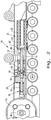
Fig. 2 is a cross-sectional view of a portion of the dozer vehicle shown inFig. 1 taken along line 2-2; -
Fig. 3 is an enlargement of a portion of the cross-sectional view shown inFig. 2 ; -
Fig. 4 is a cross-sectional view of a fluid chamber of the fluid damper shown inFigs. 2-3 connected to a restricting circuit, which is represented as a fluid flow diagram; -
Fig. 5 is a perspective view of a portion of a fluid damper shown inFigs. 2-4 ; and -
Fig. 6 is a perspective view of a coupling between the fluid damper shown inFigs. 2- 4 and an idler wheel. - Corresponding reference characters indicate corresponding parts throughout the several views. The exemplification set out herein illustrates one embodiment of the invention and such exemplification is not to be construed as limiting the scope of the invention in any manner.
- Referring now to the drawings, and more particularly to
Fig. 1 , there is shown an embodiment of a trackedwork vehicle 10, shown as a crawler dozer, according to the present invention which generally includes achassis 12, one ormore undercarriage systems 13 carried by thechassis 12 and having atrack frame 14 carrying adriving wheel 16, such as a sprocket, which rotates to drive atrack 18, and anidler system 20, which can include anoptional cover 25, carried by thetrack frame 14. Thework vehicle 10 can also include adriver compartment 21 where an operator can sit and control thework vehicle 10 during operation. As can be seen, thesprocket 16 engages thetrack 18 so that as thesprocket 16 rotates, thetrack 18 also rotates about thesprocket 16 to propel thework vehicle 10 forward and backwards. Thesprocket 16 can be coupled to an engine (not shown) or other power source of thework vehicle 10 by afinal drive 23 to provide the power needed to rotate thesprocket 16. To maintain thetrack 18 as a taut, endless track, theidler system 20 includes one ormore idler wheels 22 that engage thetrack 18. - One or more of the
idler wheels 22 can be placed at the front of theidler system 20, with thetrack 18 forming an endless track over thesprocket 16 andidler wheel 22. In some tracked vehicle configurations, one or more additional idler wheels can also be placed at the rear of theundercarriage system 13. Theidler wheel 22 exerts outward force on thetrack 18 to keep thetrack 18 taut and minimize the formation of slack in thetrack 18. It should be appreciated that thedriving wheel 16 andidler wheel 22 can have alternate arrangements to rotate thetrack 18 and keep thetrack 18 taut, with the shown embodiment illustrating only one possible arrangement. Theundercarriage system 13 can also have one ormore roller wheels 24 on the top and bottom to support theundercarriage system 13 and roll along thetrack 18 when thetrack 18 is propelled around theundercarriage system 13 by thesprocket 16. - Referring now to
Fig. 2 , a cross-sectional view of an embodiment of anidler system 20 according to the present invention is shown. Theidler system 20 includes at least oneidler wheel 22 engaged with thetrack 18, atensioner 26 coupled to the idler wheel(s) 22, arecoiler 28 coupled to thetensioner 26, and afluid damper 30 attached to thetrack frame 14 and coupled to thetensioner 26 and/or therecoiler 28. Thetensioner 26 is configured to force the idler wheel(s) 22 into engagement with thetrack 18 in order to keep thetrack 18 taut during operation. Thetensioner 26 can be, for example, a grease-filled cylinder that can increase or decrease the amount of grease in the cylinder to adjust the amount of tension applied to the idler wheel(s) 22. Thetensioner 26, therefore, keeps an outwardly applied force to the idler wheel(s) 22 during operation to minimize slack in thetrack 18. Sometimes, thetrack 18 will lengthen in certain areas, such as around thesprocket 16, which requires a compensatory decrease in the length of thetrack 18 in other areas so thetrack 18 does not get over-tensioned and/or snap. To allow for the compensatory decrease in the length of thetrack 18, thetensioner 26 is coupled to arecoiler 28 in order to allow the idler wheel(s) 22 at the front and back of theundercarriage system 13 to move closer together when a compressing force is applied, while also allowing the idler wheel(s) 22 at the front and back to be forced back outward following the compressing force being removed. Therecoiler 28 can include, for example, acompression spring 29 that compresses when the compressing force is applied to thespring 29 by the idler wheel(s) 22 through thetensioner 26. Once the compressing force is reduced and/or removed, the energy stored in thespring 29 can be spontaneously released to force the idler wheel(s) 22 back into its original operating position through thetensioner 26. This allows the idler wheel(s) 22 to spontaneously adjust to differing track conditions with a reduced risk of damaging thetrack 18 during operation. It should be appreciated that the describedtensioner 26 andrecoiler 28 are exemplary only, and any suitable tensioner and recoiler can be utilized according to the present invention. - To couple the
tensioner 26 to therecoiler 28, acylinder 30 of thetensioner 26 can be connected to arecoiler rod 32 of therecoiler 28. Thecylinder 30 can have acoupling portion 34 with anopening 36 formed therein, with acoupling end 38 of therecoiler rod 32 piloted within theopening 36 to couple with thecylinder 30. Therecoiler 28 can have thespring 29 held within arecoiler body 40. Apressing plate 42 can be held in therecoiler body 40 and forced toward anend 44 of therecoiler body 40 by thespring 29. Thepressing plate 42 can be connected to therecoiler rod 32 such that when therecoiler rod 32 is moved toward thespring 29, thepressing plate 42 applies a compressing force to thespring 29 and compresses thespring 29. Once the compressing force is reduced and/or removed, thespring 29 then forces thepressing plate 42 back toward theend 44 of therecoiler body 40, moving therecoiler rod 32 in the process. Therecoiler rod 32 then forces thetensioner 26 outward by pushing on thecoupling portion 34 of thecylinder 30, pushing the idler wheel(s) 22 outward as well. It should be appreciated that the described coupling of thetensioner 26 to therecoiler 28 is exemplary only, and other suitable ways to couple thetensioner 26 to therecoiler 28 can be utilized according to the present invention. - Referring now to
Fig. 6 , it can be seen that thetensioner 26 can apply forces to the idler wheel(s) 22 by coupling to the idler wheel(s) 22 through anidler yoke 46 connected to thecylinder 30 and also connected to an idler axle 48 (shown inFig. 2 ) defining an axis of rotation for the idler wheel(s) 22. Forces applied to thetensioner 26 can thus be transmitted to and from the idler wheel(s) 22 through the connection of theidler axle 48 to thetensioner 26 viaidler yoke 46, allowing adjustment of the idler wheel(s) 22 during operation of thework vehicle 10. - When the
recoiler 28 forces the idler wheel(s) 22 back into its original operating position from a compressed position, the outward extension of therecoiler 28 on the idler wheel(s) 22 is normally limited by a stop (such as end 44) formed in therecoiler 28 or by thetrack 18 tightening and preventing further extension of the idler wheel(s) 22. When the movement of the idler wheel(s) 22 suddenly stops, a loud noise and large shock can be created that transmits throughout thevehicle 10 and disturbs an operator in thedriver compartment 22. The operator may believe that there has been a malfunction in thevehicle 10, and cease operation of thevehicle 10 to alert service personnel to find a malfunction that does not exist. Further, the resulting shock from the sudden impact and stopping of the idler wheel(s) 22 movement can damage theundercarriage system 13 due to cracks, denting, and loosening of joints in theundercarriage system 13 around, for example, thesprocket 16, reducing the lifespan of theundercarriage system 13. - To reduce the occurrence of the loud noise and large shock, and referring now to
Figs. 2-4 , theidler system 20 according to the present invention includes afluid damper 30 which is attached to thetrack frame 14 and is coupled to thetensioner 26 and/or therecoiler 28. Thefluid damper 30 includes afluid chamber 50, shown as a cylinder, that has afirst port 52 and asecond port 54, apiston 56 coupled to thetensioner 26 and/orrecoiler 28 placed within thefluid chamber 50, and arestriction circuit 58 fluidly connected to thefirst port 52 and thesecond port 54. While thefluid chamber 50 is shown as a cylinder, thefluid chamber 50 can have any suitable shape that allows thepiston 56 within thefluid chamber 50 to couple to thetensioner 26 and/orrecoiler 28. While thetensioner 26 is shown as being coupled to therecoiler 28 within thefluid chamber 50 and thepiston 56 is shown as coupling to therecoiler rod 32 within thefluid chamber 50, it should be appreciated that the coupling between thetensioner 26 andrecoiler 28 does not need to occur in thefluid chamber 50 and thepiston 56 within thefluid chamber 50 can couple to thetensioner 26, the recoiler 28 (as shown), or both. As can be seen inFigs. 3-4 , thepiston 56 can have a piston diameter PD that is roughly equivalent to a cylinder diameter CD of thefluid chamber 50, when thefluid chamber 50 is a cylinder, to form a substantially fluid-tight seal with the walls of thefluid chamber 50, splitting thefluid chamber 50 into two sub-chambers, with each sub-chamber being on one side of thepiston 56. This allows movement of thepiston 56, through coupling to thetensioner 26 and/orrecoiler 28, to displace fluid in thefluid chamber 50 in the direction of movement, forcing the fluid to move in the forced direction. The fluid can be, for example, oil or other hydraulic fluid filling thefluid chamber 50 andrestriction circuit 58, which will be described further herein. - Referring specifically now to
Fig. 4 , it can be seen that thefirst port 52 andsecond port 54 can be formed in thefluid chamber 50 at opposite ends 60, 62 of thefluid chamber 50. The reason for forming theports ports port ports port restriction circuit 58, utilizinghoses 64 or other suitable elements, so therestriction circuit 58 andfluid chamber 50 can form a closed fluid circuit. The closed fluid circuit can be filled with the previously described fluid so movement of thepiston 56 in thefluid chamber 50 displaces fluid in thefluid chamber 50 and causes fluid flow throughout the closed fluid circuit. To ensure that the fluid in the closed fluid circuit flows through the closed fluid circuit as thepiston 56 moves, rather than the fluid compressing, the fluid in the closed fluid circuit can be a non-compressible fluid, such as the previously described oil or other hydraulic fluid. - As can be seen, the
restriction circuit 58, which is shown as a fluid flow diagram inFig. 4 , can include acheck valve 66 and arestriction orifice 68 that are arranged in parallel within therestriction circuit 58. Therestriction circuit 58 can be, for example, a valve manifold or other similar element having one or more fluid flow paths within and having acheck valve 66 and arestriction orifice 68. Thecheck valve 66 can be any type of valve that allows substantially unrestricted fluid flow therethrough in one direction, and substantially prevents fluid flow in the opposite direction. As shown inFig. 4 , thecheck valve 66 is arranged such that fluid flow through the closed fluid circuit is prevented in a fluid flow direction through thefirst port 52 toward thesecond port 54 by aball 70 of thecheck valve 66, causing any fluid flow in this direction to be forced through therestriction orifice 68. Similarly, fluid flow through the closed fluid circuit in a fluid flow direction through thesecond port 54 toward thefirst port 52 is substantially unrestricted by thecheck valve 66, as the fluid flow can force theball 70 to compress avalve spring 72 of thecheck valve 66 and allow fluid flow through thecheck valve 66. Therestriction orifice 68, on the other hand, always restricts fluid flow therethrough by having a reduced opening size compared to other flow paths through therestriction circuit 58. Therestriction orifice 68 can be a fixed size opening or be an adjustable size opening that will allow an operator to adjust the magnitude of restriction of fluid flow through therestriction orifice 68. Adjusting the size of therestriction orifice 68 may occur, for example, in response to temperature changes of the fluid in thefluid chamber 50 affecting the fluid viscosity, which is described further herein. As is known, a largersized restriction orifice 68 will be less restrictive to fluid flow than a relatively smaller sized restriction orifice, so it can be useful for an operator to adjust the size of therestriction orifice 68 to adjust the fluid flow restriction through therestriction orifice 68, the reasons for which are further described herein. In this sense, therestriction orifice 68 passively restricts fluid flow therethrough, as the geometry of therestriction orifice 68 causes the restricted fluid flow therethrough and no additional energy is required to restrict the fluid flow through therestriction orifice 68. Therestriction circuit 58 can also be connected to an accumulator 74 that will compensate for changes in fluid volume within the closed fluid circuit and can also have a shut-offvalve 76 that allows for the addition of fluid to the closed fluid circuit or the purging of air from the closed fluid circuit. - During operation, the
fluid damper 30 allows for compressing forces to be applied to therecoiler 28 with relatively little resistance while the subsequent forces applied by therecoiler 28 to the idler wheel(s) 22 are damped. This is due to thepiston 56 displacing the fluid in thefluid chamber 50 as thepiston 56 moves, causing the movement of thepiston 56 to force the fluid through theports restriction circuit 58. When thepiston 56 moves, for example, in a first direction, denoted byarrow 78, toward thespring 29 of therecoiler 28, corresponding to a compressing force acting on the idler wheel(s) 22, thepiston 56 causes fluid in thefluid chamber 50 to flow in thefirst direction 78 as well. Since thefluid chamber 50 andrestriction circuit 58 are a closed fluid circuit, thepiston 56 forces the fluid through thesecond port 54 and toward thefirst port 52 as thepiston 56 moves in thefirst direction 78. As previously described, fluid flow in this manner is substantially unrestricted due to thecheck valve 66 being arranged to allow substantially unrestricted fluid flow from thesecond port 54 toward thefirst port 52. The substantially unrestricted fluid flow through the closed fluid circuit allows therecoiler rod 32 to force thepressing plate 42 to compress thespring 29 with little fluid resistance occurring between the fluid in thefluid chamber 50 and thepiston 56, which is coupled to therecoiler rod 32 either directly or indirectly. - On the other hand, when the compressing force is reduced and/or removed and the
recoiler 28 forces therecoiler rod 32, and coupledpiston 56, in a second direction, designated byarrow 80, that is opposite to thefirst direction 78, thepiston 56 displaces fluid in thefluid chamber 50 in a manner that causes the fluid to flow in the closed fluid circuit through thefirst port 52 toward thesecond port 54. Fluid flow in this direction is not allowed through thecheck valve 66, as previously described, and thus all fluid flow in this direction must pass through therestriction orifice 68. Since therestriction orifice 68 has a reduced opening size compared to theports restriction orifice 68 is a chokepoint in the flow path that does not allow the fluid to freely flow therethrough. In other words, therestriction orifice 68 causes fluid flow through the closed fluid circuit to be a restricted fluid flow when therestriction orifice 68 is in the only fluid flow path that the fluid can take. Due to the restriction of fluid flow through therestriction orifice 68 when thepiston 56 moves in thesecond direction 80, the fluid in thefluid chamber 50 provides substantial fluid resistance to the movement of thepiston 56 through the fluid chamber in thesecond direction 80. The rate of thepiston 56 moving through thefluid chamber 50, therefore, depends on the rate of fluid displaced by the movingpiston 56 forcing fluid in the closed fluid circuit through therestriction orifice 68. If therestriction orifice 68 is made very small, for example, the rate of fluid passing through therestriction orifice 68 will be decreased, compared to a larger sized restriction orifice, and the movement speed of thepiston 56 in thesecond direction 80 will be decreased as well. The fluid resistance to thepiston 56 moving through thefluid chamber 50 in thesecond direction 80 slows down the movement speed of thepiston 56 and coupledtensioner 26, also slowing down the extension of therecoiler 28 and idler wheel(s) 22 back to the original operating position. The reduced movement speed of the elements can reduce the amount of noise and shock that transmit through thework vehicle 10 by such a degree that the operator is not even aware that therecoiler 28 has forced the idler wheel(s) 22 back to the original operating position. Thefluid damper 30 of the present invention, therefore, can allow thespring 29 to become compressed with little interference while damping the release of the energy in thespring 29 to return the idler wheel(s) 22 back to the original operating position. - As the damping ability of the
fluid damper 30 depends on the flow of fluid through the closed fluid circuit of thefluid damper 30 and corresponding resistance to the movement of thepiston 56 through thefluid chamber 50, it should be appreciated that many adjustments can be made to thefluid damper 30 to achieve desired damping characteristics. For example, the axial distance betweenports recoiler 28 moves thepiston 56 as therecoiler 28 forces the idler wheel(s) 22 back to the original operating position. Similarly, a chamber length CL of thefluid chamber 50 can be equal to the maximum recoil distance so the movement of thepiston 56 in the axial direction cannot exceed the maximum recoil distance. Therestriction circuit 58 can also be configured as desired to permit a substantially unrestricted fluid flow through the closed fluid circuit when thepiston 56 moves in thefirst direction 78 and a restricted fluid flow through the closed fluid circuit when thepiston 56 moves in thesecond direction 80 opposite thefirst direction 78. The restricted fluid flow can be caused in the closed fluid circuit by a passive element, such as therestriction orifice 68, which does not require activation to restrict the fluid flow, or a selectively activated element that is controlled to manually or automatically restrict fluid flow in the closed fluid circuit. - As can be seen in
Fig. 4 , atemperature sensor 82 can be fluidly connected to the closed fluid circuit, for example, by being fluidly connected to thehose 64 fluidly connecting thefirst port 52 to therestriction circuit 58. Thetemperature sensor 82 can be coupled to acontroller 84 which is configured to adjust the size of therestriction orifice 68. Therestriction orifice 68 can be adjusted, for example, by advancing an actuated element (not shown) in one direction in therestriction circuit 58 to decrease the size of therestriction orifice 68 and advancing the actuated element in the opposite direction to increase the size of therestriction orifice 68, with thecontroller 84 controlling how the actuated element is advanced. Thetemperature sensor 82 allows thecontroller 84 to measure the temperature of the fluid in the closed fluid circuit and, if desired, determine the viscosity of the fluid in the closed fluid circuit based on the temperature and fluid type. As is known, the viscosity of a fluid is generally inversely related to the temperature of the fluid, with higher fluid temperatures tending to lower the fluid viscosity. As the damping ability of thefluid damper 50 is affected by the ability of the fluid in the closed fluid circuit to resist the movement of thepiston 56 due to viscosity, variable viscosities caused by temperature changes can cause undesired damping ability of thefluid damper 50. Thecontroller 84 can compensate for variable viscosities by adjusting the size of therestriction orifice 68 in response to a measured temperature and/or determined viscosity of the fluid in the closed fluid circuit. For example, thecontroller 84 can be programmed to make the restriction orifice 68 a certain size at a first temperature, and then decrease the size of therestriction orifice 68 at a second temperature which is higher than the first temperature in order to maintain an equivalent restricted fluid flow through the closed fluid circuit despite a lowered viscosity of the fluid when the fluid is the higher second temperature rather than the first temperature. Thecontroller 84 can be programmed, for example, to continuously adjust the size of therestriction orifice 68 by utilizing an algorithm correlating the temperature and/or viscosity of the fluid to an associated restriction opening size, so each change in the fluid temperature and/or viscosity causes a corresponding change in the size of therestriction orifice 68. Alternatively, thecontroller 84 can be programmed to adjust the size of therestriction orifice 68 at certain fluid temperature setpoints so thecontroller 84 will only adjust the size of therestriction orifice 68 to a certain size once the temperature of the fluid in the closed fluid circuit reaches a certain temperature. It should be appreciated that the described ways of thecontroller 84 adjusting the size of therestriction orifice 68 are exemplary only, and thecontroller 84 can adjust the size of therestriction orifice 68 in response to events other than temperature/viscosity change, such as the fluid in the closed fluid circuit being replaced. - Referring now to
Fig. 5 , thefluid chamber 50 is shown attached to thetrack frame 14 and coupled to thetensioner 26 and therecoiler 28. Therestriction circuit 58 is not shown inFig. 5 , but can also be attached to thetrack frame 14, as shown inFigs. 2-3 . Since the fluid flow resistance in thefluid damper 30 arises from the flow restriction at therestriction orifice 68, the damped force caused by thepiston 56 flowing against the resisting fluid in thefluid chamber 50 gets transmitted to thefluid damper 30. Thefluid damper 30 being attached to thetrack frame 14 allows thefluid damper 30 to be grounded to thetrack frame 14, and the energy of therecoiler 28 forcing the idler wheel(s) 22 back to the original operating position is grounded in thefluid damper 30 to thetrack frame 14. This allows for therecoiler 28 to operate as it does in currently known systems, but significantly reduces the accompanying loud noise and shock. It should therefore be appreciated that thefluid damper 30 according to the present invention can be incorporated in many different types of track vehicles with tensioners and recoilers with relative ease and few changes to the track vehicle design. - While this invention has been described with respect to at least one embodiment, the present invention can be further modified within the spirit and scope of this disclosure. This application is therefore intended to cover any variations, uses, or adaptations of the invention using its general principles. Further, this application is intended to cover such departures from the present disclosure as come within known or customary practice in the art to which this invention pertains and which fall within the limits of the appended claims.
Claims (10)
- A track vehicle (10), comprising:a track frame (14);a driving wheel (16) carried by said track frame (14) and configured to rotate;a track (18) rotatably engaged with said driving wheel (16);at least one idler wheel (22) engaged with said track (18);a tensioner (26) coupled to said at least one idler wheel (22) and configured to force said at least one idler wheel (22) into engagement with said track (18); anda recoiler (28) coupled to said tensioner (26);characterized by:a fluid damper (30) attached to said track frame (14) and coupled to said tensioner (26) and said recoiler (28), said fluid damper (30) comprising:a fluid chamber (50) having a first port (52) and a second port (54);a piston (56) coupled to said tensioner (26) and/or said recoiler (28) within said fluid chamber (50); anda restriction circuit (58) fluidly connected to said first port (52) and said second port (54) and configured to form a closed fluid circuit, said restriction circuit (58) configured to permit a substantially unrestricted fluid flow through said closed fluid circuit when said piston (56) moves in a first direction (78) and a restricted fluid flow through said closed fluid circuit when said piston (56) moves in a second direction (80) opposite to said first direction (78).
- The track vehicle (10) of claim 1, wherein said restriction circuit (58) includes a check valve (66) and a restriction orifice (68).
- The track vehicle (10) of claim 2, wherein said check valve (66) and said restriction orifice (68) are arranged in parallel.
- The track vehicle (10) of claims 2 to 3, wherein said restriction orifice (68) is an adjustable size opening or a fixed size opening.
- The track vehicle (10) of claim 4, further comprising a temperature sensor (82) fluidly connected to said closed fluid circuit and a controller (84) coupled to said temperature sensor (82).
- The track vehicle (10) of claim 5, wherein said restriction orifice (68) is an adjustable size opening and said controller (84) is configured to adjust said adjustable size opening (68) based on a temperature and/or a viscosity of a fluid in said closed fluid circuit.
- The track vehicle (10) of claim 1, wherein said first port (52) is formed adjacent a first end (60) of said fluid chamber (50) and said second port (54) is formed adjacent a second end (62) of said fluid chamber (50) opposite said first end (60).
- The track vehicle (10) of any of the preceding claims, wherein said recoiler (28) is a compression spring.
- The track vehicle (10) of any of the preceding claims, wherein said piston (56) travels toward said recoiler (28) in said first direction (78) and said piston (56) travels toward said idler wheel (22) in said second direction (80).
- The track vehicle (10) of claim 9, wherein fluid flow through said closed fluid circuit is passively restricted when said piston (56) moves in said second direction (80).
Applications Claiming Priority (1)
| Application Number | Priority Date | Filing Date | Title |
|---|---|---|---|
| US15/014,649 US10336382B2 (en) | 2016-02-03 | 2016-02-03 | Track vehicle with fluidly damped idler recoil system |
Publications (2)
| Publication Number | Publication Date |
|---|---|
| EP3202648A1 true EP3202648A1 (en) | 2017-08-09 |
| EP3202648B1 EP3202648B1 (en) | 2019-09-25 |
Family
ID=57963039
Family Applications (1)
| Application Number | Title | Priority Date | Filing Date |
|---|---|---|---|
| EP17154109.7A Active EP3202648B1 (en) | 2016-02-03 | 2017-02-01 | Track vehicle with fluidly damped idler recoil system |
Country Status (3)
| Country | Link |
|---|---|
| US (1) | US10336382B2 (en) |
| EP (1) | EP3202648B1 (en) |
| BR (1) | BR102017002243B1 (en) |
Families Citing this family (4)
| Publication number | Priority date | Publication date | Assignee | Title |
|---|---|---|---|---|
| CN109068588B (en) * | 2016-04-27 | 2022-05-17 | 苏州宝时得电动工具有限公司 | Intelligent crawler-type mobile equipment |
| DE102017116428A1 (en) * | 2017-07-20 | 2019-01-24 | Komatsu Germany Gmbh | Assembly arrangement for tensioning units in tracked chassis of large machines |
| US20220049726A1 (en) * | 2018-12-13 | 2022-02-17 | Agco Corporation | Controlled cylinder retraction with a closed hydraulic system |
| US11667342B2 (en) | 2019-10-03 | 2023-06-06 | Deere & Company | Active track-chain sag management systems for crawler vehicles |
Citations (4)
| Publication number | Priority date | Publication date | Assignee | Title |
|---|---|---|---|---|
| US4149757A (en) * | 1977-01-27 | 1979-04-17 | Caterpillar Tractor Co. | Automatic track chain tensioner |
| DE3507805A1 (en) * | 1985-03-05 | 1986-09-18 | Liebherr-Werk Telfs GmbH, Telfs | DEVICE FOR TENSIONING THE CHAIN OF CHAIN VEHICLES |
| US20030117017A1 (en) * | 2001-12-21 | 2003-06-26 | Hoff Brian D. | Track tension adjustment management system |
| US20030122422A1 (en) * | 2001-12-31 | 2003-07-03 | Hoff Brian D. | Track tension adjustment management actuator |
Family Cites Families (10)
| Publication number | Priority date | Publication date | Assignee | Title |
|---|---|---|---|---|
| US3765730A (en) | 1970-07-31 | 1973-10-16 | Komatsu Mfg Co Ltd | Device for automatically adjusting track shoe assembly in crawler tractor |
| US3901563A (en) | 1974-05-17 | 1975-08-26 | Caterpillar Tractor Co | Hydromechanical recoil and track adjuster system |
| JPS597183Y2 (en) | 1979-08-29 | 1984-03-05 | 株式会社小松製作所 | Track adjustment device for tracked vehicles |
| JPS61155073A (en) | 1984-12-27 | 1986-07-14 | Hitachi Constr Mach Co Ltd | Caterpillar tensile force adjusting device for track-laying type vehicle |
| US5511868A (en) | 1994-10-12 | 1996-04-30 | Caterpillar Inc. | Booster recoil mechanism for endless track machine |
| US5984436A (en) * | 1997-12-19 | 1999-11-16 | Caterpillar Inc. | Hydraulic track tensioning circuit |
| US6305762B1 (en) * | 1999-12-16 | 2001-10-23 | Caterpillar Inc. | Valve assembly for controlling actuation of an actuator of a track tensioning system |
| GB2388347A (en) * | 2002-05-11 | 2003-11-12 | Ford New Holland Nv | Endless track tension system |
| JP2004314938A (en) * | 2003-03-31 | 2004-11-11 | Komatsu Ltd | Crawler tension adjusting device |
| US7914087B2 (en) | 2007-09-14 | 2011-03-29 | Deere & Company | Automatic track tensioning system |
-
2016
- 2016-02-03 US US15/014,649 patent/US10336382B2/en active Active
-
2017
- 2017-02-01 EP EP17154109.7A patent/EP3202648B1/en active Active
- 2017-02-02 BR BR102017002243-9A patent/BR102017002243B1/en active IP Right Grant
Patent Citations (4)
| Publication number | Priority date | Publication date | Assignee | Title |
|---|---|---|---|---|
| US4149757A (en) * | 1977-01-27 | 1979-04-17 | Caterpillar Tractor Co. | Automatic track chain tensioner |
| DE3507805A1 (en) * | 1985-03-05 | 1986-09-18 | Liebherr-Werk Telfs GmbH, Telfs | DEVICE FOR TENSIONING THE CHAIN OF CHAIN VEHICLES |
| US20030117017A1 (en) * | 2001-12-21 | 2003-06-26 | Hoff Brian D. | Track tension adjustment management system |
| US20030122422A1 (en) * | 2001-12-31 | 2003-07-03 | Hoff Brian D. | Track tension adjustment management actuator |
Also Published As
| Publication number | Publication date |
|---|---|
| BR102017002243A2 (en) | 2017-12-12 |
| EP3202648B1 (en) | 2019-09-25 |
| US20170217517A1 (en) | 2017-08-03 |
| BR102017002243B1 (en) | 2023-04-04 |
| US10336382B2 (en) | 2019-07-02 |
Similar Documents
| Publication | Publication Date | Title |
|---|---|---|
| US11286013B2 (en) | Dynamic tensioner locking device for a track system and method thereof | |
| EP3202648B1 (en) | Track vehicle with fluidly damped idler recoil system | |
| US10640162B2 (en) | Tensioning system for an endless track system | |
| US8764129B2 (en) | Track over tire system and method | |
| US3645586A (en) | Track-adjusting and recoil mechanism | |
| JP4310103B2 (en) | Tension adjustment mechanism for work machines | |
| CN109562800B (en) | Track system for work vehicle | |
| JP4237482B2 (en) | Crawler belt tension adjustment management actuator | |
| CN210235140U (en) | Track tensioning mechanism and tracked vehicle | |
| CA1306485C (en) | Tensioning and recoil system for a tracked vehicle | |
| EP3894307B1 (en) | Controlled cylinder retraction with a closed hydraulic system | |
| GB2393696A (en) | Tensioning system for a tracked vehicle | |
| US20160318566A1 (en) | Track tensioner | |
| AU2080288A (en) | Track recoil and tensioning mechanism | |
| US3477766A (en) | Apparatus for tensioning a track or the like | |
| US11046375B2 (en) | Track roller unit for an agricultural working machine | |
| CA2982193C (en) | Dynamic tensioner locking device for a track system and method thereof | |
| CA2129178A1 (en) | Track tensioning system for tracked vehicles | |
| JP4594752B2 (en) | Track tension adjusting device for crawler traveling device | |
| JP2009274630A (en) | Tension regulation apparatus of crawler-mounted travel device | |
| JPH0526770U (en) | Crawler type traveling device | |
| KR980008983A (en) | Infinitely variable track tensioning device for infinite track vehicles | |
| JPH025625B2 (en) | ||
| JP2009255730A (en) | Working machine |
Legal Events
| Date | Code | Title | Description |
|---|---|---|---|
| PUAI | Public reference made under article 153(3) epc to a published international application that has entered the european phase |
Free format text: ORIGINAL CODE: 0009012 |
|
| STAA | Information on the status of an ep patent application or granted ep patent |
Free format text: STATUS: THE APPLICATION HAS BEEN PUBLISHED |
|
| AK | Designated contracting states |
Kind code of ref document: A1 Designated state(s): AL AT BE BG CH CY CZ DE DK EE ES FI FR GB GR HR HU IE IS IT LI LT LU LV MC MK MT NL NO PL PT RO RS SE SI SK SM TR |
|
| AX | Request for extension of the european patent |
Extension state: BA ME |
|
| STAA | Information on the status of an ep patent application or granted ep patent |
Free format text: STATUS: REQUEST FOR EXAMINATION WAS MADE |
|
| 17P | Request for examination filed |
Effective date: 20180209 |
|
| RBV | Designated contracting states (corrected) |
Designated state(s): AL AT BE BG CH CY CZ DE DK EE ES FI FR GB GR HR HU IE IS IT LI LT LU LV MC MK MT NL NO PL PT RO RS SE SI SK SM TR |
|
| GRAP | Despatch of communication of intention to grant a patent |
Free format text: ORIGINAL CODE: EPIDOSNIGR1 |
|
| STAA | Information on the status of an ep patent application or granted ep patent |
Free format text: STATUS: GRANT OF PATENT IS INTENDED |
|
| INTG | Intention to grant announced |
Effective date: 20190416 |
|
| GRAS | Grant fee paid |
Free format text: ORIGINAL CODE: EPIDOSNIGR3 |
|
| GRAA | (expected) grant |
Free format text: ORIGINAL CODE: 0009210 |
|
| STAA | Information on the status of an ep patent application or granted ep patent |
Free format text: STATUS: THE PATENT HAS BEEN GRANTED |
|
| AK | Designated contracting states |
Kind code of ref document: B1 Designated state(s): AL AT BE BG CH CY CZ DE DK EE ES FI FR GB GR HR HU IE IS IT LI LT LU LV MC MK MT NL NO PL PT RO RS SE SI SK SM TR |
|
| REG | Reference to a national code |
Ref country code: GB Ref legal event code: FG4D |
|
| REG | Reference to a national code |
Ref country code: CH Ref legal event code: EP |
|
| REG | Reference to a national code |
Ref country code: AT Ref legal event code: REF Ref document number: 1183566 Country of ref document: AT Kind code of ref document: T Effective date: 20191015 |
|
| REG | Reference to a national code |
Ref country code: IE Ref legal event code: FG4D |
|
| REG | Reference to a national code |
Ref country code: DE Ref legal event code: R096 Ref document number: 602017007220 Country of ref document: DE |
|
| REG | Reference to a national code |
Ref country code: NL Ref legal event code: MP Effective date: 20190925 |
|
| PG25 | Lapsed in a contracting state [announced via postgrant information from national office to epo] |
Ref country code: NO Free format text: LAPSE BECAUSE OF FAILURE TO SUBMIT A TRANSLATION OF THE DESCRIPTION OR TO PAY THE FEE WITHIN THE PRESCRIBED TIME-LIMIT Effective date: 20191225 Ref country code: HR Free format text: LAPSE BECAUSE OF FAILURE TO SUBMIT A TRANSLATION OF THE DESCRIPTION OR TO PAY THE FEE WITHIN THE PRESCRIBED TIME-LIMIT Effective date: 20190925 Ref country code: BG Free format text: LAPSE BECAUSE OF FAILURE TO SUBMIT A TRANSLATION OF THE DESCRIPTION OR TO PAY THE FEE WITHIN THE PRESCRIBED TIME-LIMIT Effective date: 20191225 Ref country code: LT Free format text: LAPSE BECAUSE OF FAILURE TO SUBMIT A TRANSLATION OF THE DESCRIPTION OR TO PAY THE FEE WITHIN THE PRESCRIBED TIME-LIMIT Effective date: 20190925 Ref country code: FI Free format text: LAPSE BECAUSE OF FAILURE TO SUBMIT A TRANSLATION OF THE DESCRIPTION OR TO PAY THE FEE WITHIN THE PRESCRIBED TIME-LIMIT Effective date: 20190925 Ref country code: SE Free format text: LAPSE BECAUSE OF FAILURE TO SUBMIT A TRANSLATION OF THE DESCRIPTION OR TO PAY THE FEE WITHIN THE PRESCRIBED TIME-LIMIT Effective date: 20190925 |
|
| REG | Reference to a national code |
Ref country code: LT Ref legal event code: MG4D |
|
| PG25 | Lapsed in a contracting state [announced via postgrant information from national office to epo] |
Ref country code: GR Free format text: LAPSE BECAUSE OF FAILURE TO SUBMIT A TRANSLATION OF THE DESCRIPTION OR TO PAY THE FEE WITHIN THE PRESCRIBED TIME-LIMIT Effective date: 20191226 Ref country code: RS Free format text: LAPSE BECAUSE OF FAILURE TO SUBMIT A TRANSLATION OF THE DESCRIPTION OR TO PAY THE FEE WITHIN THE PRESCRIBED TIME-LIMIT Effective date: 20190925 Ref country code: LV Free format text: LAPSE BECAUSE OF FAILURE TO SUBMIT A TRANSLATION OF THE DESCRIPTION OR TO PAY THE FEE WITHIN THE PRESCRIBED TIME-LIMIT Effective date: 20190925 |
|
| REG | Reference to a national code |
Ref country code: AT Ref legal event code: MK05 Ref document number: 1183566 Country of ref document: AT Kind code of ref document: T Effective date: 20190925 |
|
| PG25 | Lapsed in a contracting state [announced via postgrant information from national office to epo] |
Ref country code: RO Free format text: LAPSE BECAUSE OF FAILURE TO SUBMIT A TRANSLATION OF THE DESCRIPTION OR TO PAY THE FEE WITHIN THE PRESCRIBED TIME-LIMIT Effective date: 20190925 Ref country code: AL Free format text: LAPSE BECAUSE OF FAILURE TO SUBMIT A TRANSLATION OF THE DESCRIPTION OR TO PAY THE FEE WITHIN THE PRESCRIBED TIME-LIMIT Effective date: 20190925 Ref country code: EE Free format text: LAPSE BECAUSE OF FAILURE TO SUBMIT A TRANSLATION OF THE DESCRIPTION OR TO PAY THE FEE WITHIN THE PRESCRIBED TIME-LIMIT Effective date: 20190925 Ref country code: AT Free format text: LAPSE BECAUSE OF FAILURE TO SUBMIT A TRANSLATION OF THE DESCRIPTION OR TO PAY THE FEE WITHIN THE PRESCRIBED TIME-LIMIT Effective date: 20190925 Ref country code: PL Free format text: LAPSE BECAUSE OF FAILURE TO SUBMIT A TRANSLATION OF THE DESCRIPTION OR TO PAY THE FEE WITHIN THE PRESCRIBED TIME-LIMIT Effective date: 20190925 Ref country code: PT Free format text: LAPSE BECAUSE OF FAILURE TO SUBMIT A TRANSLATION OF THE DESCRIPTION OR TO PAY THE FEE WITHIN THE PRESCRIBED TIME-LIMIT Effective date: 20200127 Ref country code: ES Free format text: LAPSE BECAUSE OF FAILURE TO SUBMIT A TRANSLATION OF THE DESCRIPTION OR TO PAY THE FEE WITHIN THE PRESCRIBED TIME-LIMIT Effective date: 20190925 Ref country code: NL Free format text: LAPSE BECAUSE OF FAILURE TO SUBMIT A TRANSLATION OF THE DESCRIPTION OR TO PAY THE FEE WITHIN THE PRESCRIBED TIME-LIMIT Effective date: 20190925 |
|
| PG25 | Lapsed in a contracting state [announced via postgrant information from national office to epo] |
Ref country code: CZ Free format text: LAPSE BECAUSE OF FAILURE TO SUBMIT A TRANSLATION OF THE DESCRIPTION OR TO PAY THE FEE WITHIN THE PRESCRIBED TIME-LIMIT Effective date: 20190925 Ref country code: IS Free format text: LAPSE BECAUSE OF FAILURE TO SUBMIT A TRANSLATION OF THE DESCRIPTION OR TO PAY THE FEE WITHIN THE PRESCRIBED TIME-LIMIT Effective date: 20200224 Ref country code: SK Free format text: LAPSE BECAUSE OF FAILURE TO SUBMIT A TRANSLATION OF THE DESCRIPTION OR TO PAY THE FEE WITHIN THE PRESCRIBED TIME-LIMIT Effective date: 20190925 Ref country code: SM Free format text: LAPSE BECAUSE OF FAILURE TO SUBMIT A TRANSLATION OF THE DESCRIPTION OR TO PAY THE FEE WITHIN THE PRESCRIBED TIME-LIMIT Effective date: 20190925 |
|
| REG | Reference to a national code |
Ref country code: DE Ref legal event code: R097 Ref document number: 602017007220 Country of ref document: DE |
|
| PG2D | Information on lapse in contracting state deleted |
Ref country code: IS |
|
| PG25 | Lapsed in a contracting state [announced via postgrant information from national office to epo] |
Ref country code: DK Free format text: LAPSE BECAUSE OF FAILURE TO SUBMIT A TRANSLATION OF THE DESCRIPTION OR TO PAY THE FEE WITHIN THE PRESCRIBED TIME-LIMIT Effective date: 20190925 Ref country code: IS Free format text: LAPSE BECAUSE OF FAILURE TO SUBMIT A TRANSLATION OF THE DESCRIPTION OR TO PAY THE FEE WITHIN THE PRESCRIBED TIME-LIMIT Effective date: 20200126 |
|
| PLBE | No opposition filed within time limit |
Free format text: ORIGINAL CODE: 0009261 |
|
| STAA | Information on the status of an ep patent application or granted ep patent |
Free format text: STATUS: NO OPPOSITION FILED WITHIN TIME LIMIT |
|
| 26N | No opposition filed |
Effective date: 20200626 |
|
| REG | Reference to a national code |
Ref country code: CH Ref legal event code: PL |
|
| REG | Reference to a national code |
Ref country code: BE Ref legal event code: MM Effective date: 20200229 |
|
| PG25 | Lapsed in a contracting state [announced via postgrant information from national office to epo] |
Ref country code: LU Free format text: LAPSE BECAUSE OF NON-PAYMENT OF DUE FEES Effective date: 20200201 Ref country code: MC Free format text: LAPSE BECAUSE OF FAILURE TO SUBMIT A TRANSLATION OF THE DESCRIPTION OR TO PAY THE FEE WITHIN THE PRESCRIBED TIME-LIMIT Effective date: 20190925 |
|
| PG25 | Lapsed in a contracting state [announced via postgrant information from national office to epo] |
Ref country code: LI Free format text: LAPSE BECAUSE OF NON-PAYMENT OF DUE FEES Effective date: 20200229 Ref country code: CH Free format text: LAPSE BECAUSE OF NON-PAYMENT OF DUE FEES Effective date: 20200229 Ref country code: SI Free format text: LAPSE BECAUSE OF FAILURE TO SUBMIT A TRANSLATION OF THE DESCRIPTION OR TO PAY THE FEE WITHIN THE PRESCRIBED TIME-LIMIT Effective date: 20190925 |
|
| PG25 | Lapsed in a contracting state [announced via postgrant information from national office to epo] |
Ref country code: IE Free format text: LAPSE BECAUSE OF NON-PAYMENT OF DUE FEES Effective date: 20200201 |
|
| PG25 | Lapsed in a contracting state [announced via postgrant information from national office to epo] |
Ref country code: BE Free format text: LAPSE BECAUSE OF NON-PAYMENT OF DUE FEES Effective date: 20200229 |
|
| PG25 | Lapsed in a contracting state [announced via postgrant information from national office to epo] |
Ref country code: TR Free format text: LAPSE BECAUSE OF FAILURE TO SUBMIT A TRANSLATION OF THE DESCRIPTION OR TO PAY THE FEE WITHIN THE PRESCRIBED TIME-LIMIT Effective date: 20190925 Ref country code: MT Free format text: LAPSE BECAUSE OF FAILURE TO SUBMIT A TRANSLATION OF THE DESCRIPTION OR TO PAY THE FEE WITHIN THE PRESCRIBED TIME-LIMIT Effective date: 20190925 Ref country code: CY Free format text: LAPSE BECAUSE OF FAILURE TO SUBMIT A TRANSLATION OF THE DESCRIPTION OR TO PAY THE FEE WITHIN THE PRESCRIBED TIME-LIMIT Effective date: 20190925 |
|
| PG25 | Lapsed in a contracting state [announced via postgrant information from national office to epo] |
Ref country code: MK Free format text: LAPSE BECAUSE OF FAILURE TO SUBMIT A TRANSLATION OF THE DESCRIPTION OR TO PAY THE FEE WITHIN THE PRESCRIBED TIME-LIMIT Effective date: 20190925 |
|
| REG | Reference to a national code |
Ref country code: FR Ref legal event code: PLFP Year of fee payment: 7 |
|
| PGFP | Annual fee paid to national office [announced via postgrant information from national office to epo] |
Ref country code: FR Payment date: 20230222 Year of fee payment: 7 |
|
| PGFP | Annual fee paid to national office [announced via postgrant information from national office to epo] |
Ref country code: IT Payment date: 20230210 Year of fee payment: 7 Ref country code: GB Payment date: 20230220 Year of fee payment: 7 Ref country code: DE Payment date: 20230223 Year of fee payment: 7 |