EP3202639A1 - Steering system - Google Patents
Steering system Download PDFInfo
- Publication number
- EP3202639A1 EP3202639A1 EP17154035.4A EP17154035A EP3202639A1 EP 3202639 A1 EP3202639 A1 EP 3202639A1 EP 17154035 A EP17154035 A EP 17154035A EP 3202639 A1 EP3202639 A1 EP 3202639A1
- Authority
- EP
- European Patent Office
- Prior art keywords
- yoke
- shaft
- angle
- steering
- intermediate shaft
- Prior art date
- Legal status (The legal status is an assumption and is not a legal conclusion. Google has not performed a legal analysis and makes no representation as to the accuracy of the status listed.)
- Granted
Links
Images



Classifications
-
- F—MECHANICAL ENGINEERING; LIGHTING; HEATING; WEAPONS; BLASTING
- F16—ENGINEERING ELEMENTS AND UNITS; GENERAL MEASURES FOR PRODUCING AND MAINTAINING EFFECTIVE FUNCTIONING OF MACHINES OR INSTALLATIONS; THERMAL INSULATION IN GENERAL
- F16D—COUPLINGS FOR TRANSMITTING ROTATION; CLUTCHES; BRAKES
- F16D3/00—Yielding couplings, i.e. with means permitting movement between the connected parts during the drive
- F16D3/16—Universal joints in which flexibility is produced by means of pivots or sliding or rolling connecting parts
- F16D3/26—Hooke's joints or other joints with an equivalent intermediate member to which each coupling part is pivotally or slidably connected
- F16D3/38—Hooke's joints or other joints with an equivalent intermediate member to which each coupling part is pivotally or slidably connected with a single intermediate member with trunnions or bearings arranged on two axes perpendicular to one another
- F16D3/382—Hooke's joints or other joints with an equivalent intermediate member to which each coupling part is pivotally or slidably connected with a single intermediate member with trunnions or bearings arranged on two axes perpendicular to one another constructional details of other than the intermediate member
- F16D3/387—Fork construction; Mounting of fork on shaft; Adapting shaft for mounting of fork
-
- B—PERFORMING OPERATIONS; TRANSPORTING
- B62—LAND VEHICLES FOR TRAVELLING OTHERWISE THAN ON RAILS
- B62D—MOTOR VEHICLES; TRAILERS
- B62D1/00—Steering controls, i.e. means for initiating a change of direction of the vehicle
- B62D1/02—Steering controls, i.e. means for initiating a change of direction of the vehicle vehicle-mounted
- B62D1/16—Steering columns
- B62D1/20—Connecting steering column to steering gear
-
- F—MECHANICAL ENGINEERING; LIGHTING; HEATING; WEAPONS; BLASTING
- F16—ENGINEERING ELEMENTS AND UNITS; GENERAL MEASURES FOR PRODUCING AND MAINTAINING EFFECTIVE FUNCTIONING OF MACHINES OR INSTALLATIONS; THERMAL INSULATION IN GENERAL
- F16D—COUPLINGS FOR TRANSMITTING ROTATION; CLUTCHES; BRAKES
- F16D1/00—Couplings for rigidly connecting two coaxial shafts or other movable machine elements
- F16D1/06—Couplings for rigidly connecting two coaxial shafts or other movable machine elements for attachment of a member on a shaft or on a shaft-end
- F16D1/08—Couplings for rigidly connecting two coaxial shafts or other movable machine elements for attachment of a member on a shaft or on a shaft-end with clamping hub; with hub and longitudinal key
- F16D1/0847—Couplings for rigidly connecting two coaxial shafts or other movable machine elements for attachment of a member on a shaft or on a shaft-end with clamping hub; with hub and longitudinal key with radial clamping due to a radial screw
-
- F—MECHANICAL ENGINEERING; LIGHTING; HEATING; WEAPONS; BLASTING
- F16—ENGINEERING ELEMENTS AND UNITS; GENERAL MEASURES FOR PRODUCING AND MAINTAINING EFFECTIVE FUNCTIONING OF MACHINES OR INSTALLATIONS; THERMAL INSULATION IN GENERAL
- F16D—COUPLINGS FOR TRANSMITTING ROTATION; CLUTCHES; BRAKES
- F16D1/00—Couplings for rigidly connecting two coaxial shafts or other movable machine elements
- F16D1/06—Couplings for rigidly connecting two coaxial shafts or other movable machine elements for attachment of a member on a shaft or on a shaft-end
- F16D1/08—Couplings for rigidly connecting two coaxial shafts or other movable machine elements for attachment of a member on a shaft or on a shaft-end with clamping hub; with hub and longitudinal key
- F16D1/0852—Couplings for rigidly connecting two coaxial shafts or other movable machine elements for attachment of a member on a shaft or on a shaft-end with clamping hub; with hub and longitudinal key with radial clamping between the mating surfaces of the hub and shaft
- F16D1/0864—Couplings for rigidly connecting two coaxial shafts or other movable machine elements for attachment of a member on a shaft or on a shaft-end with clamping hub; with hub and longitudinal key with radial clamping between the mating surfaces of the hub and shaft due to tangential loading of the hub, e.g. a split hub
-
- F—MECHANICAL ENGINEERING; LIGHTING; HEATING; WEAPONS; BLASTING
- F16—ENGINEERING ELEMENTS AND UNITS; GENERAL MEASURES FOR PRODUCING AND MAINTAINING EFFECTIVE FUNCTIONING OF MACHINES OR INSTALLATIONS; THERMAL INSULATION IN GENERAL
- F16C—SHAFTS; FLEXIBLE SHAFTS; ELEMENTS OR CRANKSHAFT MECHANISMS; ROTARY BODIES OTHER THAN GEARING ELEMENTS; BEARINGS
- F16C3/00—Shafts; Axles; Cranks; Eccentrics
- F16C3/02—Shafts; Axles
- F16C3/03—Shafts; Axles telescopic
-
- F—MECHANICAL ENGINEERING; LIGHTING; HEATING; WEAPONS; BLASTING
- F16—ENGINEERING ELEMENTS AND UNITS; GENERAL MEASURES FOR PRODUCING AND MAINTAINING EFFECTIVE FUNCTIONING OF MACHINES OR INSTALLATIONS; THERMAL INSULATION IN GENERAL
- F16D—COUPLINGS FOR TRANSMITTING ROTATION; CLUTCHES; BRAKES
- F16D1/00—Couplings for rigidly connecting two coaxial shafts or other movable machine elements
- F16D1/06—Couplings for rigidly connecting two coaxial shafts or other movable machine elements for attachment of a member on a shaft or on a shaft-end
- F16D1/08—Couplings for rigidly connecting two coaxial shafts or other movable machine elements for attachment of a member on a shaft or on a shaft-end with clamping hub; with hub and longitudinal key
- F16D1/0894—Couplings for rigidly connecting two coaxial shafts or other movable machine elements for attachment of a member on a shaft or on a shaft-end with clamping hub; with hub and longitudinal key with other than axial keys, e.g. diametral pins, cotter pins and no other radial clamping
-
- F—MECHANICAL ENGINEERING; LIGHTING; HEATING; WEAPONS; BLASTING
- F16—ENGINEERING ELEMENTS AND UNITS; GENERAL MEASURES FOR PRODUCING AND MAINTAINING EFFECTIVE FUNCTIONING OF MACHINES OR INSTALLATIONS; THERMAL INSULATION IN GENERAL
- F16D—COUPLINGS FOR TRANSMITTING ROTATION; CLUTCHES; BRAKES
- F16D1/00—Couplings for rigidly connecting two coaxial shafts or other movable machine elements
- F16D1/10—Quick-acting couplings in which the parts are connected by simply bringing them together axially
- F16D1/108—Quick-acting couplings in which the parts are connected by simply bringing them together axially having retaining means rotating with the coupling and acting by interengaging parts, i.e. positive coupling
- F16D1/116—Quick-acting couplings in which the parts are connected by simply bringing them together axially having retaining means rotating with the coupling and acting by interengaging parts, i.e. positive coupling the interengaging parts including a continuous or interrupted circumferential groove in the surface of one of the coupling parts
-
- F—MECHANICAL ENGINEERING; LIGHTING; HEATING; WEAPONS; BLASTING
- F16—ENGINEERING ELEMENTS AND UNITS; GENERAL MEASURES FOR PRODUCING AND MAINTAINING EFFECTIVE FUNCTIONING OF MACHINES OR INSTALLATIONS; THERMAL INSULATION IN GENERAL
- F16D—COUPLINGS FOR TRANSMITTING ROTATION; CLUTCHES; BRAKES
- F16D1/00—Couplings for rigidly connecting two coaxial shafts or other movable machine elements
- F16D1/10—Quick-acting couplings in which the parts are connected by simply bringing them together axially
- F16D2001/103—Quick-acting couplings in which the parts are connected by simply bringing them together axially the torque is transmitted via splined connections
-
- F—MECHANICAL ENGINEERING; LIGHTING; HEATING; WEAPONS; BLASTING
- F16—ENGINEERING ELEMENTS AND UNITS; GENERAL MEASURES FOR PRODUCING AND MAINTAINING EFFECTIVE FUNCTIONING OF MACHINES OR INSTALLATIONS; THERMAL INSULATION IN GENERAL
- F16D—COUPLINGS FOR TRANSMITTING ROTATION; CLUTCHES; BRAKES
- F16D2250/00—Manufacturing; Assembly
- F16D2250/0061—Joining
-
- F—MECHANICAL ENGINEERING; LIGHTING; HEATING; WEAPONS; BLASTING
- F16—ENGINEERING ELEMENTS AND UNITS; GENERAL MEASURES FOR PRODUCING AND MAINTAINING EFFECTIVE FUNCTIONING OF MACHINES OR INSTALLATIONS; THERMAL INSULATION IN GENERAL
- F16D—COUPLINGS FOR TRANSMITTING ROTATION; CLUTCHES; BRAKES
- F16D2250/00—Manufacturing; Assembly
- F16D2250/0061—Joining
- F16D2250/0076—Welding, brazing
Definitions
- the invention relates to a steering system.
- a steering system generally includes an intermediate shaft that couples a steering shaft on which a steering wheel is installed to a pinion shaft of a steering gear.
- a universal joint is interposed between the intermediate shaft and the steering shaft and between the intermediate shaft and the pinion shaft. See, for example, Japanese Patent Application Publication No. 2015-110988 ( JP 2015-110988 A ).
- the universal joint between the intermediate shaft and the pinion shaft is coupled to the pinion shaft via a bolt.
- the bolt is attached in a direction in which an attachment operation is not easy, an operation of assembling the universal joint in the steering system may be inefficient.
- An object of the invention is to provide a steering system that can be more efficiently assembled in a vehicle body.
- a steering system in an aspect of the invention includes an intermediate shaft to which a turning force of a steering member is transmitted through a first end of the intermediate shaft, a first universal joint coupled to the first end of the intermediate shaft, and a second universal joint coupled to a second end of the intermediate shaft.
- the first universal joint includes a first yoke coupled to the intermediate shaft and a second yoke paired with the first yoke
- the second universal joint includes a third yoke coupled to the intermediate shaft, a fourth yoke paired with the third yoke, and a shaft attachment portion coupled to the fourth yoke and via which a shaft is attached to the fourth yoke.
- a bolt insertion hole is formed in the shaft attachment portion to allow the shaft to be clamped.
- an angle between the intermediate shaft and a shaft coupled to the second yoke is set to ⁇ 1
- an around-axis angle of the first yoke in a rotating direction around an axial direction is set to ⁇ 1
- an angle between the intermediate shaft and the shaft coupled to the fourth yoke is set to ⁇ 2
- a junction angle between the fourth yoke and the shaft attachment portion in the rotating direction is adjusted to set an around-axis angle of the bolt insertion hole in the shaft attachment portion in the rotating direction to a preset angle ⁇ 2.
- the steering system in this aspect when the angle between the intermediate shaft and the shaft coupled to the second yoke is set to ⁇ 1, the around-axis angle of the first yoke in the rotating direction around the axial direction is set to ⁇ 1, and the angle between the intermediate shaft and the shaft coupled to the fourth yoke is set to ⁇ 2, the junction angle between the fourth yoke and the shaft attachment portion in the rotating direction is adjusted to set the around-axis angle of the bolt insertion hole in the shaft attachment portion in the rotating direction to the angle (preset angle) ⁇ 2, at which an operation of inserting the bolt through the bolt insertion hole is facilitated.
- the steering system can be more efficiently assembled into the vehicle body.
- a pair of arm portions of the first yoke may be arranged in a vertical direction or a lateral direction when the steering member is in a steering neutral position.
- the arm portions of the first yoke are arranged in the vertical direction or the lateral direction.
- a torsional rigidity of the intermediate shaft varies in the same manner regardless of whether a driver of a vehicle steers the steering member rightward or leftward with respect to the steering neutral position.
- the driver of the vehicle have the same steering feeling regardless of whether the driver steers the steering member rightward or leftward with respect to the steering neutral position. This allows the steering system to be more efficiently assembled into the vehicle body without undermining the driver's favorable steering feeling.
- the fourth yoke and the shaft attachment portion may be serration-fitted together.
- the junction angle between the fourth yoke and the shaft attachment portion can be easily adjusted.
- the fourth yoke and the shaft attachment portion may be joined together.
- the fourth yoke and the shaft attachment portion are joined together and thus firmly fixed together.
- FIG. 1 is a schematic diagram of a steering system 1 according to a first embodiment of the invention.
- the steering system 1 includes an intermediate shaft 4 to which a turning force of a steering member 2 such as a steering wheel is transmitted through a first end 4A via a steering shaft 3 to which the steering member 2 is coupled at a first end of the steering shaft 3.
- the intermediate shaft 4 transmits the turning force to a steering operation mechanism A which steers steered wheels W.
- the steering system 1 further includes a first universal joint 9 coupled to the first end 4A (the end closer to the steering member 2) and the steering shaft 3 and a second universal joint 10 coupled to a second end 4B (an end opposite to the steering member 2) of the intermediate shaft 4 and a pinion shaft 5 of the steering operation mechanism A.
- the intermediate shaft 4 is extendable and retractable in an axial direction X of the intermediate shaft 4 and includes a first shaft 11 and a second shaft 12 fitted together by, for example, splining, so as to be relatively movable and integrally rotatable.
- the first universal joint 9 is coupled to the first shaft 11, and the second universal joint 10 is coupled to the second shaft 12.
- a pinion 5A is formed which meshes with a rack 6A formed on a rack shaft 6 forming the steering operation mechanism A along with the pinion shaft 5.
- the rack shaft 6 is shaped like a rod that is elongate in a lateral direction H and that extends horizontally rightward and leftward in the vehicle.
- the rack shaft 6 is inserted through a rack housing 7.
- the lateral direction H corresponds to a vehicle width direction.
- Tie rods 8 are coupled to respective ends of the rack shaft 6 in the lateral direction H.
- the tie rods 8 are coupled to the steered wheels W via respective knuckle arms (not depicted in the drawings).
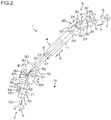
- FIG. 2 is a side view depicting a periphery of the intermediate shaft 4.
- members of the steering system are illustrated with the lateral direction H set to coincide with a direction perpendicular to the sheet of the drawing.
- a rotating direction S hereinafter refers to a rotating direction around a central axis C1 of the steering shaft 3, a rotating direction around a central axis C2 of the intermediate shaft 4, and a rotating direction around a central axis C3 of the pinion shaft 5.
- the rotating direction S is a direction around the axial direction of the steering shaft 3, the intermediate shaft 4, and the pinion shaft 5.
- the first universal joint 9 includes a first yoke 20 coupled to the intermediate shaft 4, a second yoke 30 paired with the first yoke 20, and a joint spider 40 that couples the first yoke 20 and the second yoke 30 together so as to make the first yoke 20 and the second yoke 30 relatively displaceable.
- the first yoke 20 integrally includes a flange portion 22 fixed to the first end 4A of the intermediate shaft 4 by welding or the like and a pair of first arm portions 21 extending in the axial direction X from the first end 4A and facing each other across the central axis C2.
- the second yoke 30 includes a tubular portion 31 through which the steering shaft 3 is inserted and a pair of clamping plates 32 extending from the tubular portion 31 and clamping the steering shaft 3 via the tubular portion 31.
- the second yoke 30 further includes a pair of second arm portions 34 extending from the tubular portion 31 in an axial direction thereof and facing each other across the central axis C1 at a position displaced from the position of the first arm portions 21 in the rotating direction S by 90° along the rotating direction S.
- the tubular portion 31, the clamping plates 32, and the second arm portions 34 are integrally formed.
- a clamping bolt 36 is inserted through the clamping plates 32 to clamp the steering shaft 3.
- the clamping bolt 36 clamps the clamping plates 32 together to clamp the steering shaft 3 in the tubular portion 31.
- the second universal joint 10 includes a third yoke 50 coupled to the intermediate shaft 4, a fourth yoke 60 paired with the third yoke 50, a shaft attachment portion 70 joined to the fourth yoke 60 and via which the pinion shaft 5 is attached to the fourth yoke 60, and a joint spider 80 that couples the third yoke 50 and the fourth yoke 60 together so as to make the third yoke 50 and the fourth yoke 60 relatively displaceable.
- the fourth yoke 60 and the shaft attachment portion 70 are serration-fitted together and joined together by welding.
- the third yoke 50 integrally includes a flange portion 52 fixed to a second end 4B of the intermediate shaft 4 by welding or the like and a pair of third arm portions 51 extending in the axial direction X from the flange portion 52 and facing each other across the central axis C2.
- the fourth yoke 60 includes a flange portion 62 joined to the shaft attachment portion 70 and a pair of fourth arm portions 63 extending in an axial direction Z in which the central axis C3 extends and facing each other at a position displaced from the position of the third arm portions 51 by 90° in the rotating direction S.
- An angle between the intermediate shaft 4 and the steering shaft 3 as viewed in the lateral direction H is designated as an angle ⁇ .
- the angle ⁇ is 0° when the steering shaft 3 and the intermediate shaft 4 are arranged coaxially and adjacent to each other in the axial direction X.
- An angle between the intermediate shaft 4 and the pinion shaft 5 as viewed in the lateral direction H is designated as an angle ⁇ .
- the angle ⁇ is 0° when the intermediate shaft 4 and the pinion shaft 5 are arranged coaxially and adjacent to each other in the axial direction X.
- the angle P is set to an angle ⁇ 1 preset in accordance with specifications or the like
- the angle ⁇ is set to an angle ⁇ 2 preset in accordance with the specifications or the like
- the first universal joint 9 and the second universal joint 10 are arranged at predetermined positions in the rotating direction S.
- the pinion shaft 5 is inserted through the shaft attachment portion 70 of the second universal joint 10, and the pinion shaft 5 is attached to the shaft attachment portion 70 with the clamping bolt 74.
- the following description relates to a coupling structure for the second universal joint 10 and the pinion shaft 5, and the positions of the first universal joint 9 and the second universal joint 10 in the rotating direction S.
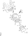
- FIG. 3 is an exploded perspective view of a periphery of the fourth yoke 60 and the shaft attachment portion 70 of the second universal joint 10.
- the shaft attachment portion 70 integrally includes a tubular portion 71 externally fitted over a shaft such as the pinion shaft 5 and a pair of clamping plates 72 extending from the tubular portion 71 and configured to clamp a shaft such as the pinion shaft 5 via the tubular portion 71; the tubular portion 71 and the clamping plates 72 are formed into a single member.
- a slit 71A is formed which extends along the axial direction Z of the tubular portion 71 between the clamping plates 72.
- an internal serration 71B is formed which is serration-fitted to an external serration 5B formed at an end of the pinion shaft 5.
- a bolt insertion hole 73 is formed in each of the clamping plates 72 to allow the shaft such as the pinion shaft 5 to be clamped.
- a clamping bolt 74 is inserted through the bolt insertion holes 73.
- the clamping bolt 74 is fitted in a peripheral groove 5C of the pinion shaft 5 (see also FIG. 2 ).
- the clamping bolt 74 allows retaining of the pinion shaft 5 in the tubular portion 71 to be achieved.
- the clamping bolt 74 clamps the clamping plates 72 together to clamp the pinion shaft 5 in the tubular portion 71.
- the tubular portion 71 is serration-fitted to the flange portion 62.
- An external serration 71C is formed in a portion of an outer peripheral surface of the tubular portion 71 that is closer to the flange portion 62 than the clamping plates 72.
- an insertion hole 62A is formed through which the tubular portion 71 is inserted.
- an internal serration 62B is formed which is serration-fitted to the external serration 71C.
- the fourth yoke 60 and the shaft attachment portion 70 are not limited to junction based on welding but may be joined together by clinching or friction welding.
- the clinching is performed on the fourth yoke 60 and the shaft attachment portion 70 serration fitted together, by plastically deforming the flange portion 62 of the fourth yoke 60 or the tubular portion 71 of the shaft attachment portion 70 to couple the flange portion 62 and the tubular portion 71 together.
- the length of the serration fitting between the tubular portion 71 and the flange portion 62 is adjusted to allow adjustment of the sum (yoke length) of the lengths of the fourth yoke 60 and the shaft attachment portion 70 in the axial direction.
- the fourth yoke 60 and the shaft attachment portion 70 may be joined together by clinching or frictional welding with the yoke length adjusted.
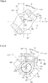
- FIG. 4 is a schematic sectional view taken along line IV-IV in FIG. 2 .
- illustration of the joint spider 80 is omitted for convenience of description.
- the first arm portions 21 of the first yoke 20 are depicted by a long dashed double-short dashed line for convenience of description.
- a clockwise direction along the rotating direction S as viewed from a side opposite to the steering member 2 is designated as an S1 direction.
- a counterclockwise direction along the rotating direction S as viewed from the side opposite to the steering member 2 is designated as an S2 direction.
- a line L0 hereinafter indicates a virtual line intersecting the central axis C2 and extending horizontally (in the lateral direction H).
- a line L1 indicates a virtual line intersecting the central axis C2 and extending in a direction in which the first arm portions 21 face each other.
- the line L1 is displaced from the line L0 by an around-axis angle ⁇ in the S1 direction.
- the around-axis angle ⁇ is represented by an angle smaller than 360° (0° ⁇ ⁇ ⁇ 360°).
- the around-axis angle is set to the angle ⁇ 1 preset in accordance with the specifications or the like.
- the angle ⁇ 1 is set such that, with the steering member 2 located in the steering neutral position, the around-axis angle ⁇ is 90° or 270°.
- the steering neutral position refers to the position of the steering member 2 in the rotating direction S during straight traveling of the vehicle.
- the first arm portions 21 are arranged in the vertical direction (the direction orthogonal to the lateral direction H). In this state, the line L1 and the line L0 are orthogonal to each other.
- a line L3 indicates a virtual line intersecting the central axis C2 and extending in a direction in which the third arm portions 51 face each other.
- the line L3 is displaced from the line L1 by a phase angle ⁇ in the S1 direction (0° ⁇ ⁇ ⁇ 360°).
- the phase angle ⁇ is set to an angle ⁇ 3 at which a turning force from the steering shaft 3 can be efficiently transmitted to the pinion shaft 5.
- FIG. 5 is a schematic diagram of a periphery of the second universal joint 10 as viewed in the direction of arrow V in FIG. 2 .
- illustration of the pinion shaft 5 and the third yoke 50 is omitted for convenience of description.
- the line L3 extending in the direction in which the third arm portions 51 face each other is depicted for convenience of description.
- a line L4 indicates a virtual line intersecting the central axis C3 and extending in a direction in which the fourth arm portions 63 face each other.
- the fourth arm portions 63 face each other at a position displaced from the position of the third arm portions 51 by 90°, and thus, the line L4 is orthogonal to the line L3.
- a line L5 indicates a virtual line intersecting the central axis C3 and a central axis CB of the bolt insertion hole 73.
- a bolt insertion direction B in which the clamping bolt 74 is inserted into the bolt insertion hole 73 extends along the central axis CB.
- the angle between the line L0 and the line L5 is designated as an around-axis angle ⁇ of the bolt insertion hole 73 in the rotating direction S.
- the around-axis angle ⁇ is represented by an angle smaller than 360° (0° ⁇ ⁇ ⁇ 360°).
- the around-axis angle ⁇ of the bolt insertion hole 73 in the rotating direction S is set to an angle ⁇ 2 preset in accordance with the specifications or the like.
- the angle ⁇ 2 refers to an angle to which the bolt insertion direction B is preset so as to facilitate an operation of inserting the clamping bolt 74 into the second universal joint 10.
- the angle ⁇ between the intermediate shaft 4 and the steering shaft 3 is set to the preset angle ⁇ 1 and the angle ⁇ between the intermediate shaft 4 and the pinion shaft 5 is set to the preset angle ⁇ 2, that is, when the phase angle ⁇ is set to the angle ⁇ 3 and the around-axis angle ⁇ of the first arm portions 21 of the first yoke 20 is set to the preset angle ⁇ 1, a junction angle ⁇ between the fourth yoke 60 and the shaft attachment portion 70 in the rotating direction S is adjusted (0° ⁇ ⁇ ⁇ 360°) so as to set the around-axis angle ⁇ of the bolt insertion hole 73 in the shaft attachment portion 70 in the rotating direction S to the angle ⁇ 2.
- the junction angle ⁇ refers to an angle between the line L4 and the line L5.
- the junction angle ⁇ between the fourth yoke 60 and the shaft attachment portion 70 in the rotating direction S can be adjusted so as to set the around-axis angle ⁇ of the bolt insertion hole 73 in the shaft attachment portion 70 in the rotating direction S to the angle ⁇ 2, at which the operation of inserting the clamping bolt 74 into the bolt insertion hole 73 is facilitated.
- the steering system 1 can be more efficiently assembled into the vehicle body.
- the shaft attachment portion 70 with the bolt insertion hole 73 formed therein is serration-fitted to the fourth arm portions 63 to enable the around-axis angle ⁇ of the bolt insertion hole 73 in the rotating direction S to be set to the angle ⁇ 2. Consequently, the junction angle ⁇ between the fourth yoke 60 and the shaft attachment portion 70 can be easily adjusted.
- the fourth yoke 60 and the shaft attachment portion 70 are joined together by weld clinching, friction welding, or the like. Thus, the fourth yoke 60 and the shaft attachment portion 70 can be firmly fixed together.
- the shaft attachment portion 70 and the fourth yoke 60 are firmly fixed together by serration fitting, welding, or the like, even when a separately formed shaft attachment portion 70 and a separately formed fourth yoke 60 are used for the second universal joint 10, the rigidity and strength of the intermediate shaft 4 can be maintained.
- FIG. 6 is a graph illustrating a relation between the around-axis angle ⁇ of the first yoke 20 and torsional rigidity of the intermediate shaft 4.
- an axis of abscissas represents the around-axis angle (°) ⁇
- an axis of ordinate represents the torsional rigidity (Nm/°) of the intermediate shaft 4.
- the torsional rigidity of the intermediate shaft 4 varies with a period of 180°, and thus, illustration of a part of the graph in which the around-axis angle ⁇ is larger than 180° is omitted.
- the torsional rigidity of the intermediate shaft 4 is highest when the around-axis angle ⁇ is 90°, and is lowest when the around-axis angle ⁇ is 180°.
- the first arm portions 21 of the first yoke 20 are arranged in the vertical direction when the steering member 2 is in the steering neutral position.
- the around-axis angle ⁇ is 90° when the steering member 2 is in the steering neutral position.
- the torsional rigidity of the intermediate shaft 4 is highest when the steering member 2 is in the steering neutral position, and decreases when the steering member 2 is steered with respect to the steering neutral position such that the manner of the decrease is the same regardless of whether the steering member 2 is steered rightward or leftward.
- the driver of the vehicle has the same stable steering feeling regardless of whether the steering member 2 is steered rightward or leftward with respect to the steering neutral position. This allows the steering system 1 to be more efficiently assembled into the vehicle body without undermining the driver's favorable steering feeling.
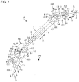
- FIG. 7 is a side view depicting a periphery of the intermediate shaft 4 in the steering system 1P.
- members of the steering system are illustrated with the lateral direction H set to coincide with a direction perpendicular to the sheet of the drawing.
- FIG. 8 is a schematic sectional view taken along line VIII-VIII in FIG. 7 .
- members of the second embodiment similar to the corresponding members described above are denoted by the same reference numerals and will thus not be described.
- the steering system 1P according to the second embodiment is different from the steering system 1 according to the first embodiment (see FIG. 2 ) in that first arm portions 21P of a first yoke 20P of a first universal joint 9P are arranged in the lateral direction H when the steering member 2 is in the steering neutral position.
- a line L1P indicates a virtual line intersecting the central axis C2 and extending in a direction in which first arm portions 21 P face each other.
- the line L1P is located at a position displaced from the line L0 by the around-axis angle ⁇ in the S 1 direction.
- the around-axis angle ⁇ is represented by an angle smaller than 360° (0° ⁇ ⁇ ⁇ 360°).
- the around-axis angle ⁇ is set to the preset angle ⁇ 1.
- the angle ⁇ 1 is set such that the around-axis angle ⁇ is 0° or 180° when the steering member 2 (see FIG. 7 ) is in the steering neutral position. In this state, the line L1P overlaps the line L0.
- the virtual line L3 extending in the direction in which the third arm portions 51 of the third yoke 50 in the rotating direction S face each other is located at a position displaced from the line L1P by the phase angle ⁇ in the S2 direction (0° ⁇ ⁇ ⁇ 360°).
- the angle ⁇ 1 is set such that the around-axis angle ⁇ is 0° or 180° when the steering member 2 is in the steering neutral position.
- the second embodiment produces the same effects as those of the first embodiment. That is, when the angle P is set to ⁇ 1, the around-axis angle ⁇ is set to ⁇ 1, and the angle ⁇ is set to ⁇ 2, the junction angle ⁇ between the fourth yoke 60 and the shaft attachment portion 70 can be adjusted so as to set the around-axis angle ⁇ of the bolt insertion hole 73 in the shaft attachment portion 70 in the rotating direction S to the angle ⁇ 2, at which the operation of inserting the clamping bolt 74 into the bolt insertion hole 73 is facilitated.
- the steering system 1 can be more efficiently assembled into the vehicle body.
- the first arm portions 21P of the first yoke 20P are arranged in the lateral direction when the steering member 2 is in the steering neutral position.
- the around-axis angle ⁇ is 0° or 180° when the steering member 2 is in the steering neutral position.
- the torsional rigidity of the intermediate shaft 4 is lowest when the steering member 2 is in the steering neutral position (see FIG. 6 ), and increases when the steering member 2 is steered with respect to the steering neutral position such that the manner of the increases is the same regardless of whether the steering member 2 is steered rightward or leftward.
- the driver of the vehicle has the same smooth steering feeling regardless of whether the steering member 2 is steered rightward or leftward with respect to the steering neutral position. This allows the steering system 1 to be more efficiently assembled into the vehicle body without undermining the driver's favorable steering feeling.
- the external serration 71 C may be omitted from the tubular portion 71, and the internal serration 62B may be omitted from the flange portion 62.
- the tubular portion 71 and the flange portion 62 are joined together while being supported with a jig or the like with the junction angle ⁇ adjusted to set the around-axis angle ⁇ of the bolt insertion hole 73 in the rotating direction S to the angle ⁇ 2.
- Examples of a method for the junction include welding and clinching.
- the fourth yoke 60 may be a casting with the junction angle ⁇ pre-adjusted to set the around-axis angle ⁇ of the bolt insertion hole 73 in the rotating direction S to the angle ⁇ 2.
- the angle ⁇ 1 need not necessarily be set so as to arrange the first arm portions 21, 21P in the vertical direction or the lateral direction at the steering neutral position.
- the angle ⁇ 1 may be set so as to minimize adverse effects of vibration input through the steered wheels W or the like. This enables a reduction in the degree of elimination of possible backlash between the members of the steering system 1 and also enables a reduction in rubber (not depicted in the drawings) or the like provided in the steering system 1 to prevent possible vibration.
Landscapes
- Engineering & Computer Science (AREA)
- General Engineering & Computer Science (AREA)
- Mechanical Engineering (AREA)
- Chemical & Material Sciences (AREA)
- Combustion & Propulsion (AREA)
- Transportation (AREA)
- Steering Controls (AREA)
- Vehicle Body Suspensions (AREA)
Abstract
Description
- The invention relates to a steering system.
- A steering system generally includes an intermediate shaft that couples a steering shaft on which a steering wheel is installed to a pinion shaft of a steering gear. A universal joint is interposed between the intermediate shaft and the steering shaft and between the intermediate shaft and the pinion shaft. See, for example, Japanese Patent Application Publication No.
2015-110988 JP 2015-110988 A - As disclosed in
JP 2015-110988 A - An object of the invention is to provide a steering system that can be more efficiently assembled in a vehicle body.
- A steering system in an aspect of the invention includes an intermediate shaft to which a turning force of a steering member is transmitted through a first end of the intermediate shaft, a first universal joint coupled to the first end of the intermediate shaft, and a second universal joint coupled to a second end of the intermediate shaft. The first universal joint includes a first yoke coupled to the intermediate shaft and a second yoke paired with the first yoke, and the second universal joint includes a third yoke coupled to the intermediate shaft, a fourth yoke paired with the third yoke, and a shaft attachment portion coupled to the fourth yoke and via which a shaft is attached to the fourth yoke. A bolt insertion hole is formed in the shaft attachment portion to allow the shaft to be clamped. When an angle between the intermediate shaft and a shaft coupled to the second yoke is set to θ1, an around-axis angle of the first yoke in a rotating direction around an axial direction is set to ω1, and an angle between the intermediate shaft and the shaft coupled to the fourth yoke is set to θ2, a junction angle between the fourth yoke and the shaft attachment portion in the rotating direction is adjusted to set an around-axis angle of the bolt insertion hole in the shaft attachment portion in the rotating direction to a preset angle ω2.
- In the steering system in this aspect, when the angle between the intermediate shaft and the shaft coupled to the second yoke is set to θ1, the around-axis angle of the first yoke in the rotating direction around the axial direction is set to ω1, and the angle between the intermediate shaft and the shaft coupled to the fourth yoke is set to θ2, the junction angle between the fourth yoke and the shaft attachment portion in the rotating direction is adjusted to set the around-axis angle of the bolt insertion hole in the shaft attachment portion in the rotating direction to the angle (preset angle) ω2, at which an operation of inserting the bolt through the bolt insertion hole is facilitated. Thus, the steering system can be more efficiently assembled into the vehicle body.
- In the steering system in the above-described aspect, with the around-axis angle of the first yoke set to ω1, a pair of arm portions of the first yoke may be arranged in a vertical direction or a lateral direction when the steering member is in a steering neutral position.
- In the steering system in the above-described aspect, with the around-axis angle of the first yoke set to ω1, the arm portions of the first yoke are arranged in the vertical direction or the lateral direction. Thus, a torsional rigidity of the intermediate shaft varies in the same manner regardless of whether a driver of a vehicle steers the steering member rightward or leftward with respect to the steering neutral position. Thus, the driver of the vehicle have the same steering feeling regardless of whether the driver steers the steering member rightward or leftward with respect to the steering neutral position. This allows the steering system to be more efficiently assembled into the vehicle body without undermining the driver's favorable steering feeling.
- In the steering system in the above-described aspect, the fourth yoke and the shaft attachment portion may be serration-fitted together.
- In the steering system in the above-described aspect, since the fourth yoke and the shaft attachment portion are serration-fitted together, the junction angle between the fourth yoke and the shaft attachment portion can be easily adjusted.
- In the steering system in the above-described aspect, the fourth yoke and the shaft attachment portion may be joined together.
- In the steering system in the above-described aspect, the fourth yoke and the shaft attachment portion are joined together and thus firmly fixed together.
- The foregoing and further features and advantages of the invention will become apparent from the following description of example embodiments with reference to the accompanying drawings, wherein like numerals are used to represent like elements and wherein:
-
FIG. 1 is a schematic diagram of a steering system according to a first embodiment of the invention; -
FIG. 2 is a side view depicting a periphery of an intermediate shaft; -
FIG. 3 is an exploded perspective view of a periphery of a fourth yoke and a shaft attachment portion of a second universal joint; -
FIG. 4 is a schematic sectional view taken along line IV-IV inFIG. 2 ; -
FIG. 5 is a schematic diagram of a periphery of the second universal joint as viewed in the direction of arrow V inFIG. 2 ; -
FIG. 6 is a graph illustrating a relation between an around-axis angle of a first yoke and a torsional rigidity of the intermediate shaft; -
FIG. 7 is a side view depicting a periphery of an intermediate shaft of a steering system according to a second embodiment of the invention; and -
FIG. 8 is a schematic sectional view taken along line VIII-VIII inFIG. 7 . - Embodiments of the invention will be described below with reference to the attached drawings.
-
FIG. 1 is a schematic diagram of a steering system 1 according to a first embodiment of the invention. The steering system 1 includes anintermediate shaft 4 to which a turning force of asteering member 2 such as a steering wheel is transmitted through afirst end 4A via asteering shaft 3 to which thesteering member 2 is coupled at a first end of thesteering shaft 3. Theintermediate shaft 4 transmits the turning force to a steering operation mechanism A which steers steered wheels W. - The steering system 1 further includes a first
universal joint 9 coupled to thefirst end 4A (the end closer to the steering member 2) and thesteering shaft 3 and a seconduniversal joint 10 coupled to asecond end 4B (an end opposite to the steering member 2) of theintermediate shaft 4 and apinion shaft 5 of the steering operation mechanism A. - The
intermediate shaft 4 is extendable and retractable in an axial direction X of theintermediate shaft 4 and includes afirst shaft 11 and asecond shaft 12 fitted together by, for example, splining, so as to be relatively movable and integrally rotatable. The firstuniversal joint 9 is coupled to thefirst shaft 11, and the seconduniversal joint 10 is coupled to thesecond shaft 12. - On the
pinion shaft 5, apinion 5A is formed which meshes with arack 6A formed on arack shaft 6 forming the steering operation mechanism A along with thepinion shaft 5. Therack shaft 6 is shaped like a rod that is elongate in a lateral direction H and that extends horizontally rightward and leftward in the vehicle. Therack shaft 6 is inserted through arack housing 7. The lateral direction H corresponds to a vehicle width direction.Tie rods 8 are coupled to respective ends of therack shaft 6 in the lateral direction H. Thetie rods 8 are coupled to the steered wheels W via respective knuckle arms (not depicted in the drawings). -
FIG. 2 is a side view depicting a periphery of theintermediate shaft 4. InFIG. 2 , members of the steering system are illustrated with the lateral direction H set to coincide with a direction perpendicular to the sheet of the drawing. - A rotating direction S hereinafter refers to a rotating direction around a central axis C1 of the
steering shaft 3, a rotating direction around a central axis C2 of theintermediate shaft 4, and a rotating direction around a central axis C3 of thepinion shaft 5. The rotating direction S is a direction around the axial direction of thesteering shaft 3, theintermediate shaft 4, and thepinion shaft 5. - As seen in
FIG. 2 , the firstuniversal joint 9 includes afirst yoke 20 coupled to theintermediate shaft 4, asecond yoke 30 paired with thefirst yoke 20, and ajoint spider 40 that couples thefirst yoke 20 and thesecond yoke 30 together so as to make thefirst yoke 20 and thesecond yoke 30 relatively displaceable. - The
first yoke 20 integrally includes aflange portion 22 fixed to thefirst end 4A of theintermediate shaft 4 by welding or the like and a pair offirst arm portions 21 extending in the axial direction X from thefirst end 4A and facing each other across the central axis C2. - The
second yoke 30 includes atubular portion 31 through which thesteering shaft 3 is inserted and a pair ofclamping plates 32 extending from thetubular portion 31 and clamping thesteering shaft 3 via thetubular portion 31. Thesecond yoke 30 further includes a pair ofsecond arm portions 34 extending from thetubular portion 31 in an axial direction thereof and facing each other across the central axis C1 at a position displaced from the position of thefirst arm portions 21 in the rotating direction S by 90° along the rotating direction S. Thetubular portion 31, theclamping plates 32, and thesecond arm portions 34 are integrally formed. - A clamping
bolt 36 is inserted through theclamping plates 32 to clamp thesteering shaft 3. The clampingbolt 36 clamps theclamping plates 32 together to clamp thesteering shaft 3 in thetubular portion 31. - The second
universal joint 10 includes athird yoke 50 coupled to theintermediate shaft 4, afourth yoke 60 paired with thethird yoke 50, ashaft attachment portion 70 joined to thefourth yoke 60 and via which thepinion shaft 5 is attached to thefourth yoke 60, and ajoint spider 80 that couples thethird yoke 50 and thefourth yoke 60 together so as to make thethird yoke 50 and thefourth yoke 60 relatively displaceable. Thefourth yoke 60 and theshaft attachment portion 70 are serration-fitted together and joined together by welding. - The
third yoke 50 integrally includes aflange portion 52 fixed to asecond end 4B of theintermediate shaft 4 by welding or the like and a pair ofthird arm portions 51 extending in the axial direction X from theflange portion 52 and facing each other across the central axis C2. - The
fourth yoke 60 includes aflange portion 62 joined to theshaft attachment portion 70 and a pair offourth arm portions 63 extending in an axial direction Z in which the central axis C3 extends and facing each other at a position displaced from the position of thethird arm portions 51 by 90° in the rotating direction S. - An angle between the
intermediate shaft 4 and thesteering shaft 3 as viewed in the lateral direction H is designated as an angle β. The angle β is 0° when thesteering shaft 3 and theintermediate shaft 4 are arranged coaxially and adjacent to each other in the axial direction X. - An angle between the
intermediate shaft 4 and thepinion shaft 5 as viewed in the lateral direction H is designated as an angle γ. The angle γ is 0° when theintermediate shaft 4 and thepinion shaft 5 are arranged coaxially and adjacent to each other in the axial direction X. - When the steering system 1 as described above is assembled into a vehicle body, the following operation is performed. The angle P is set to an angle θ1 preset in accordance with specifications or the like, the angle γ is set to an angle θ2 preset in accordance with the specifications or the like, and the first
universal joint 9 and the seconduniversal joint 10 are arranged at predetermined positions in the rotating direction S. Then, thepinion shaft 5 is inserted through theshaft attachment portion 70 of the seconduniversal joint 10, and thepinion shaft 5 is attached to theshaft attachment portion 70 with the clampingbolt 74. - The following description relates to a coupling structure for the second
universal joint 10 and thepinion shaft 5, and the positions of the firstuniversal joint 9 and the second universal joint 10 in the rotating direction S. -
FIG. 3 is an exploded perspective view of a periphery of thefourth yoke 60 and theshaft attachment portion 70 of the seconduniversal joint 10. - As seen in
FIG. 3 , theshaft attachment portion 70 integrally includes atubular portion 71 externally fitted over a shaft such as thepinion shaft 5 and a pair of clampingplates 72 extending from thetubular portion 71 and configured to clamp a shaft such as thepinion shaft 5 via thetubular portion 71; thetubular portion 71 and theclamping plates 72 are formed into a single member. - In the
tubular portion 71, aslit 71A is formed which extends along the axial direction Z of thetubular portion 71 between the clampingplates 72. On an inner periphery of thetubular portion 71, aninternal serration 71B is formed which is serration-fitted to anexternal serration 5B formed at an end of thepinion shaft 5. - A
bolt insertion hole 73 is formed in each of the clampingplates 72 to allow the shaft such as thepinion shaft 5 to be clamped. A clampingbolt 74 is inserted through the bolt insertion holes 73. The clampingbolt 74 is fitted in aperipheral groove 5C of the pinion shaft 5 (see alsoFIG. 2 ). The clampingbolt 74 allows retaining of thepinion shaft 5 in thetubular portion 71 to be achieved. The clampingbolt 74 clamps the clampingplates 72 together to clamp thepinion shaft 5 in thetubular portion 71. - The
tubular portion 71 is serration-fitted to theflange portion 62. An external serration 71C is formed in a portion of an outer peripheral surface of thetubular portion 71 that is closer to theflange portion 62 than the clampingplates 72. In theflange portion 62, aninsertion hole 62A is formed through which thetubular portion 71 is inserted. On an inner peripheral surface of theinsertion hole 62A, aninternal serration 62B is formed which is serration-fitted to the external serration 71C. - The
fourth yoke 60 and theshaft attachment portion 70 are not limited to junction based on welding but may be joined together by clinching or friction welding. The clinching is performed on thefourth yoke 60 and theshaft attachment portion 70 serration fitted together, by plastically deforming theflange portion 62 of thefourth yoke 60 or thetubular portion 71 of theshaft attachment portion 70 to couple theflange portion 62 and thetubular portion 71 together. - The length of the serration fitting between the
tubular portion 71 and theflange portion 62 is adjusted to allow adjustment of the sum (yoke length) of the lengths of thefourth yoke 60 and theshaft attachment portion 70 in the axial direction. Thefourth yoke 60 and theshaft attachment portion 70 may be joined together by clinching or frictional welding with the yoke length adjusted. -
FIG. 4 is a schematic sectional view taken along line IV-IV inFIG. 2 . InFIG. 4 , illustration of thejoint spider 80 is omitted for convenience of description. Furthermore, inFIG. 4 , thefirst arm portions 21 of thefirst yoke 20 are depicted by a long dashed double-short dashed line for convenience of description. A clockwise direction along the rotating direction S as viewed from a side opposite to the steeringmember 2 is designated as an S1 direction. A counterclockwise direction along the rotating direction S as viewed from the side opposite to the steeringmember 2 is designated as an S2 direction. A line L0 hereinafter indicates a virtual line intersecting the central axis C2 and extending horizontally (in the lateral direction H). - A line L1 indicates a virtual line intersecting the central axis C2 and extending in a direction in which the
first arm portions 21 face each other. The line L1 is displaced from the line L0 by an around-axis angle α in the S1 direction. The around-axis angle α is represented by an angle smaller than 360° (0° ≤ α < 360°). - The around-axis angle is set to the angle ω1 preset in accordance with the specifications or the like. In the present embodiment, the angle ω1 is set such that, with the steering
member 2 located in the steering neutral position, the around-axis angle α is 90° or 270°. The steering neutral position refers to the position of the steeringmember 2 in the rotating direction S during straight traveling of the vehicle. With the steeringmember 2 in the steering neutral position, thefirst arm portions 21 are arranged in the vertical direction (the direction orthogonal to the lateral direction H). In this state, the line L1 and the line L0 are orthogonal to each other. - A line L3 indicates a virtual line intersecting the central axis C2 and extending in a direction in which the
third arm portions 51 face each other. The line L3 is displaced from the line L1 by a phase angle δ in the S1 direction (0° ≤ δ < 360°). - When the angle β between the
intermediate shaft 4 and thesteering shaft 3 is set to the angle θ1 preset in accordance with the specifications or the like and the angle γ between theintermediate shaft 4 and thepinion shaft 5 is set to the angle θ2 preset in accordance with the specifications or the like, the phase angle δ is set to an angle θ3 at which a turning force from the steeringshaft 3 can be efficiently transmitted to thepinion shaft 5. -
FIG. 5 is a schematic diagram of a periphery of the second universal joint 10 as viewed in the direction of arrow V inFIG. 2 . InFIG. 5 , illustration of thepinion shaft 5 and thethird yoke 50 is omitted for convenience of description. Furthermore, inFIG. 5 , the line L3 extending in the direction in which thethird arm portions 51 face each other is depicted for convenience of description. - As seen in
FIG. 5 , a line L4 indicates a virtual line intersecting the central axis C3 and extending in a direction in which thefourth arm portions 63 face each other. Thefourth arm portions 63 face each other at a position displaced from the position of thethird arm portions 51 by 90°, and thus, the line L4 is orthogonal to the line L3. - A line L5 indicates a virtual line intersecting the central axis C3 and a central axis CB of the
bolt insertion hole 73. A bolt insertion direction B in which theclamping bolt 74 is inserted into thebolt insertion hole 73 extends along the central axis CB. The angle between the line L0 and the line L5 is designated as an around-axis angle φ of thebolt insertion hole 73 in the rotating direction S. The around-axis angle φ is represented by an angle smaller than 360° (0° ≤ φ < 360°). - The around-axis angle φ of the
bolt insertion hole 73 in the rotating direction S is set to an angle ω2 preset in accordance with the specifications or the like. The angle ω2 refers to an angle to which the bolt insertion direction B is preset so as to facilitate an operation of inserting the clampingbolt 74 into the seconduniversal joint 10. - When the angle β between the
intermediate shaft 4 and thesteering shaft 3 is set to the preset angle θ1 and the angle γ between theintermediate shaft 4 and thepinion shaft 5 is set to the preset angle θ2, that is, when the phase angle δ is set to the angle θ3 and the around-axis angle α of thefirst arm portions 21 of thefirst yoke 20 is set to the preset angle ω1, a junction angle ε between thefourth yoke 60 and theshaft attachment portion 70 in the rotating direction S is adjusted (0° ≤ ε < 360°) so as to set the around-axis angle φ of thebolt insertion hole 73 in theshaft attachment portion 70 in the rotating direction S to the angle ω2. The junction angle ε refers to an angle between the line L4 and the line L5. - In the first embodiment, when the angle β is set to θ1, the around-axis angle α is set to ω1, and the angle γ is set to θ2, the junction angle ε between the
fourth yoke 60 and theshaft attachment portion 70 in the rotating direction S can be adjusted so as to set the around-axis angle φ of thebolt insertion hole 73 in theshaft attachment portion 70 in the rotating direction S to the angle ω2, at which the operation of inserting the clampingbolt 74 into thebolt insertion hole 73 is facilitated. Thus, the steering system 1 can be more efficiently assembled into the vehicle body. - With the junction angle ε adjusted, the
shaft attachment portion 70 with thebolt insertion hole 73 formed therein is serration-fitted to thefourth arm portions 63 to enable the around-axis angle φ of thebolt insertion hole 73 in the rotating direction S to be set to the angle ω2. Consequently, the junction angle ε between thefourth yoke 60 and theshaft attachment portion 70 can be easily adjusted. - The
fourth yoke 60 and theshaft attachment portion 70 are joined together by weld clinching, friction welding, or the like. Thus, thefourth yoke 60 and theshaft attachment portion 70 can be firmly fixed together. - Since the
shaft attachment portion 70 and thefourth yoke 60 are firmly fixed together by serration fitting, welding, or the like, even when a separately formedshaft attachment portion 70 and a separately formedfourth yoke 60 are used for the seconduniversal joint 10, the rigidity and strength of theintermediate shaft 4 can be maintained. -
FIG. 6 is a graph illustrating a relation between the around-axis angle α of thefirst yoke 20 and torsional rigidity of theintermediate shaft 4. In the graph inFIG. 6 , an axis of abscissas represents the around-axis angle (°) α, and an axis of ordinate represents the torsional rigidity (Nm/°) of theintermediate shaft 4. InFIG. 6 , the torsional rigidity of theintermediate shaft 4 varies with a period of 180°, and thus, illustration of a part of the graph in which the around-axis angle α is larger than 180° is omitted. For 0° < α ≤ 180°, the torsional rigidity of theintermediate shaft 4 is highest when the around-axis angle α is 90°, and is lowest when the around-axis angle α is 180°. - With the around-axis angle α set to the angle ω1, the
first arm portions 21 of thefirst yoke 20 are arranged in the vertical direction when the steeringmember 2 is in the steering neutral position. In other words, the around-axis angle α is 90° when the steeringmember 2 is in the steering neutral position. In this case, the torsional rigidity of theintermediate shaft 4 is highest when the steeringmember 2 is in the steering neutral position, and decreases when the steeringmember 2 is steered with respect to the steering neutral position such that the manner of the decrease is the same regardless of whether the steeringmember 2 is steered rightward or leftward. Thus, the driver of the vehicle has the same stable steering feeling regardless of whether the steeringmember 2 is steered rightward or leftward with respect to the steering neutral position. This allows the steering system 1 to be more efficiently assembled into the vehicle body without undermining the driver's favorable steering feeling. - A
steering system 1P according to a second embodiment of the invention will be described below.FIG. 7 is a side view depicting a periphery of theintermediate shaft 4 in thesteering system 1P. InFIG. 7 , members of the steering system are illustrated with the lateral direction H set to coincide with a direction perpendicular to the sheet of the drawing.FIG. 8 is a schematic sectional view taken along line VIII-VIII inFIG. 7 . InFIG. 7 andFIG. 8 , members of the second embodiment similar to the corresponding members described above are denoted by the same reference numerals and will thus not be described. - As seen in
FIG. 7 , thesteering system 1P according to the second embodiment is different from the steering system 1 according to the first embodiment (seeFIG. 2 ) in thatfirst arm portions 21P of afirst yoke 20P of a first universal joint 9P are arranged in the lateral direction H when the steeringmember 2 is in the steering neutral position. - As seen in
FIG. 8 , a line L1P indicates a virtual line intersecting the central axis C2 and extending in a direction in whichfirst arm portions 21 P face each other. The line L1P is located at a position displaced from the line L0 by the around-axis angle α in the S 1 direction. The around-axis angle α is represented by an angle smaller than 360° (0° ≤ α < 360°). - The around-axis angle α is set to the preset angle ω1. In the second embodiment, the angle ω1 is set such that the around-axis angle α is 0° or 180° when the steering member 2 (see
FIG. 7 ) is in the steering neutral position. In this state, the line L1P overlaps the line L0. - In the second embodiment, the virtual line L3 extending in the direction in which the
third arm portions 51 of thethird yoke 50 in the rotating direction S face each other is located at a position displaced from the line L1P by the phase angle δ in the S2 direction (0° ≤ δ < 360°). - In the second embodiment, the angle ω1 is set such that the around-axis angle α is 0° or 180° when the steering
member 2 is in the steering neutral position. However, the second embodiment produces the same effects as those of the first embodiment. That is, when the angle P is set to θ1, the around-axis angle α is set to ω1, and the angle γ is set to θ2, the junction angle ε between thefourth yoke 60 and theshaft attachment portion 70 can be adjusted so as to set the around-axis angle φ of thebolt insertion hole 73 in theshaft attachment portion 70 in the rotating direction S to the angle ω2, at which the operation of inserting the clampingbolt 74 into thebolt insertion hole 73 is facilitated. Thus, the steering system 1 can be more efficiently assembled into the vehicle body. - In the second embodiment, with the around-axis angle α set to the angle ω1, the
first arm portions 21P of thefirst yoke 20P are arranged in the lateral direction when the steeringmember 2 is in the steering neutral position. In other words, the around-axis angle α is 0° or 180° when the steeringmember 2 is in the steering neutral position. In this case, the torsional rigidity of theintermediate shaft 4 is lowest when the steeringmember 2 is in the steering neutral position (seeFIG. 6 ), and increases when the steeringmember 2 is steered with respect to the steering neutral position such that the manner of the increases is the same regardless of whether the steeringmember 2 is steered rightward or leftward. Thus, the driver of the vehicle has the same smooth steering feeling regardless of whether the steeringmember 2 is steered rightward or leftward with respect to the steering neutral position. This allows the steering system 1 to be more efficiently assembled into the vehicle body without undermining the driver's favorable steering feeling. - The invention is not limited to the above-described embodiments but various changes may be made to the embodiments.
- For example, the external serration 71 C may be omitted from the
tubular portion 71, and theinternal serration 62B may be omitted from theflange portion 62. In this case, thetubular portion 71 and theflange portion 62 are joined together while being supported with a jig or the like with the junction angle ε adjusted to set the around-axis angle φ of thebolt insertion hole 73 in the rotating direction S to the angle ω2. Examples of a method for the junction include welding and clinching. - Unlike in the present embodiment, the
fourth yoke 60 may be a casting with the junction angle ε pre-adjusted to set the around-axis angle φ of thebolt insertion hole 73 in the rotating direction S to the angle ω2. - The angle ω1 need not necessarily be set so as to arrange the
first arm portions
Claims (4)
- A steering system comprising:an intermediate shaft to which a turning force of a steering member is transmitted through a first end of the intermediate shaft;a first universal joint coupled to the first end of the intermediate shaft; anda second universal joint coupled to a second end of the intermediate shaft, whereinthe first universal joint includes a first yoke coupled to the intermediate shaft and a second yoke paired with the first yoke, and the second universal joint includes a third yoke coupled to the intermediate shaft, a fourth yoke paired with the third yoke, and a shaft attachment portion coupled to the fourth yoke and via which a shaft is attached to the fourth yoke,
a bolt insertion hole is formed in the shaft attachment portion to allow the shaft to be clamped, and
when an angle between the intermediate shaft and a shaft coupled to the second yoke is set to θ1, an around-axis angle of the first yoke in a rotating direction around an axial direction is set to ω1, and an angle between the intermediate shaft and the shaft coupled to the fourth yoke is set to θ2, a junction angle between the fourth yoke and the shaft attachment portion in the rotating direction is adjusted to set an around-axis angle of the bolt insertion hole in the shaft attachment portion in the rotating direction to a preset angle ω2. - The steering system according to claim 1, wherein
with the around-axis angle of the first yoke set to ω1, a pair of arm portions of the first yoke is arranged in a vertical direction or a lateral direction when the steering member is in a steering neutral position. - The steering system according to claim 1 or 2, wherein
the fourth yoke and the shaft attachment portion are serration-fitted together. - The steering system according to any one of claims 1 to 3, wherein the fourth yoke and the shaft attachment portion are joined together.
Applications Claiming Priority (1)
| Application Number | Priority Date | Filing Date | Title |
|---|---|---|---|
| JP2016017256A JP2017136889A (en) | 2016-02-01 | 2016-02-01 | Steering device |
Publications (2)
| Publication Number | Publication Date |
|---|---|
| EP3202639A1 true EP3202639A1 (en) | 2017-08-09 |
| EP3202639B1 EP3202639B1 (en) | 2019-09-18 |
Family
ID=57956146
Family Applications (1)
| Application Number | Title | Priority Date | Filing Date |
|---|---|---|---|
| EP17154035.4A Active EP3202639B1 (en) | 2016-02-01 | 2017-01-31 | Steering system |
Country Status (4)
| Country | Link |
|---|---|
| US (2) | US20170219016A1 (en) |
| EP (1) | EP3202639B1 (en) |
| JP (1) | JP2017136889A (en) |
| CN (1) | CN107054442A (en) |
Families Citing this family (5)
| Publication number | Priority date | Publication date | Assignee | Title |
|---|---|---|---|---|
| CN109533005A (en) * | 2018-11-27 | 2019-03-29 | 南京金龙新能源汽车研究院有限公司 | A kind of steering column band countershaft assembly |
| CN109630555A (en) * | 2018-12-05 | 2019-04-16 | 兰州飞行控制有限责任公司 | A kind of gear-driven assembly |
| JP7587974B2 (en) | 2020-12-09 | 2024-11-21 | 日本精工株式会社 | Yoke integrated shaft |
| JP2022143667A (en) * | 2021-03-18 | 2022-10-03 | 本田技研工業株式会社 | Vehicle steering device and its assembly method |
| DE102024130492B4 (en) * | 2024-10-21 | 2026-05-07 | Schaeffler Technologies AG & Co. KG | Articulated fork for rear axle steering |
Citations (5)
| Publication number | Priority date | Publication date | Assignee | Title |
|---|---|---|---|---|
| DE102005001082A1 (en) * | 2004-12-13 | 2006-06-14 | Rempel Stanztechnik Gmbh & Co.Kg | Method for manufacture of joint component for especially cardan joint entails fitting attachment blank or fastening flange into fork bridge and turning it by angle in relation to pivot axis according to assembly requirements |
| WO2007092764A1 (en) * | 2006-02-03 | 2007-08-16 | Drivesol Worldwide, Inc. | Assembly aid for a steering column |
| WO2013117982A1 (en) * | 2012-02-08 | 2013-08-15 | Jtekt Corporation | Universal joint and yoke |
| EP2735752A2 (en) * | 2012-11-27 | 2014-05-28 | Jtekt Corporation | Coupling structure for coupling shaft to universal joint yoke, coupling method for coupling shaft to universal joint yoke, and intermediate shaft |
| JP2015110988A (en) | 2013-06-14 | 2015-06-18 | 日本精工株式会社 | Joint-shaft coupling structure |
Family Cites Families (9)
| Publication number | Priority date | Publication date | Assignee | Title |
|---|---|---|---|---|
| JP2534772B2 (en) * | 1989-07-07 | 1996-09-18 | 日本精工株式会社 | Universal joint yoke manufacturing method |
| JPH05286444A (en) * | 1992-04-09 | 1993-11-02 | Mazda Motor Corp | Vehicular steering device and attaching method thereof |
| US5366316A (en) * | 1992-06-02 | 1994-11-22 | General Motors Corporation | Intermediate steering shaft assembly and method |
| JPH06270819A (en) * | 1993-01-22 | 1994-09-27 | Toyota Motor Corp | Steering shaft assembly method and steering mechanism |
| JPH06321118A (en) * | 1993-05-19 | 1994-11-22 | Toyota Motor Corp | Automotive steering system |
| JP4271176B2 (en) * | 2005-09-15 | 2009-06-03 | 本田技研工業株式会社 | Vehicle steering device |
| US8965743B2 (en) * | 2010-10-06 | 2015-02-24 | Nsk Ltd. | Steering device design assisting apparatus and steering device design assisting method |
| JP2013133898A (en) * | 2011-12-27 | 2013-07-08 | Nsk Ltd | Connecting part between rotary shaft and yoke of universal joint, and method of manufacturing rotary shaft |
| JP6182874B2 (en) * | 2013-01-22 | 2017-08-23 | 株式会社ジェイテクト | Steering device coupling device |
-
2016
- 2016-02-01 JP JP2016017256A patent/JP2017136889A/en active Pending
-
2017
- 2017-01-24 CN CN201710059788.7A patent/CN107054442A/en active Pending
- 2017-01-25 US US15/414,724 patent/US20170219016A1/en not_active Abandoned
- 2017-01-31 EP EP17154035.4A patent/EP3202639B1/en active Active
-
2019
- 2019-06-21 US US16/448,644 patent/US20190309802A1/en not_active Abandoned
Patent Citations (5)
| Publication number | Priority date | Publication date | Assignee | Title |
|---|---|---|---|---|
| DE102005001082A1 (en) * | 2004-12-13 | 2006-06-14 | Rempel Stanztechnik Gmbh & Co.Kg | Method for manufacture of joint component for especially cardan joint entails fitting attachment blank or fastening flange into fork bridge and turning it by angle in relation to pivot axis according to assembly requirements |
| WO2007092764A1 (en) * | 2006-02-03 | 2007-08-16 | Drivesol Worldwide, Inc. | Assembly aid for a steering column |
| WO2013117982A1 (en) * | 2012-02-08 | 2013-08-15 | Jtekt Corporation | Universal joint and yoke |
| EP2735752A2 (en) * | 2012-11-27 | 2014-05-28 | Jtekt Corporation | Coupling structure for coupling shaft to universal joint yoke, coupling method for coupling shaft to universal joint yoke, and intermediate shaft |
| JP2015110988A (en) | 2013-06-14 | 2015-06-18 | 日本精工株式会社 | Joint-shaft coupling structure |
Also Published As
| Publication number | Publication date |
|---|---|
| US20170219016A1 (en) | 2017-08-03 |
| CN107054442A (en) | 2017-08-18 |
| US20190309802A1 (en) | 2019-10-10 |
| EP3202639B1 (en) | 2019-09-18 |
| JP2017136889A (en) | 2017-08-10 |
Similar Documents
| Publication | Publication Date | Title |
|---|---|---|
| US20190309802A1 (en) | Steering system | |
| US9039041B2 (en) | Steering column anti-rotation pin | |
| JP5788829B2 (en) | Steering device | |
| US20140147197A1 (en) | Coupling structure for coupling shaft to universal joint yoke, coupling method for coupling shaft to universal joint yoke, and intermediate shaft | |
| US9765823B2 (en) | Steering apparatus | |
| WO2014119630A1 (en) | Steering column | |
| EP3315381A1 (en) | Outer column with bracket, steering column with bracket, and steering device | |
| JP6690659B2 (en) | Torque transmission shaft | |
| JP2017136889A5 (en) | ||
| JP7400731B2 (en) | Torque transmission shaft | |
| JP6673308B2 (en) | Torque transmission shaft for steering | |
| EP2796342B1 (en) | Steering device | |
| JP2008189223A (en) | Steering device shaft and manufacturing method thereof | |
| US10099718B2 (en) | Electric power steering device and method for assembling the same | |
| JP6673309B2 (en) | Torque transmission shaft | |
| JP6642551B2 (en) | Torque transmission shaft | |
| JP7119284B2 (en) | UNIVERSAL JOINT AND STEERING DEVICE WITH THE UNIVERSAL JOINT | |
| CN111065835B (en) | torque transmission shaft | |
| JP2008202742A (en) | Yoke-shaft connection structure and steering device using the same | |
| JP7099157B2 (en) | A method for manufacturing a joint portion between a shaft and a clamp member and a joint portion between a shaft and a clamp member. | |
| JP2008303980A (en) | Fitting | |
| JP4736929B2 (en) | Universal joint and shaft connection structure | |
| JP5935928B2 (en) | Steering device | |
| JP5636828B2 (en) | Universal joint and processing method thereof | |
| JP7375768B2 (en) | Steering column and steering device |
Legal Events
| Date | Code | Title | Description |
|---|---|---|---|
| PUAI | Public reference made under article 153(3) epc to a published international application that has entered the european phase |
Free format text: ORIGINAL CODE: 0009012 |
|
| STAA | Information on the status of an ep patent application or granted ep patent |
Free format text: STATUS: THE APPLICATION HAS BEEN PUBLISHED |
|
| AK | Designated contracting states |
Kind code of ref document: A1 Designated state(s): AL AT BE BG CH CY CZ DE DK EE ES FI FR GB GR HR HU IE IS IT LI LT LU LV MC MK MT NL NO PL PT RO RS SE SI SK SM TR |
|
| AX | Request for extension of the european patent |
Extension state: BA ME |
|
| STAA | Information on the status of an ep patent application or granted ep patent |
Free format text: STATUS: REQUEST FOR EXAMINATION WAS MADE |
|
| 17P | Request for examination filed |
Effective date: 20180208 |
|
| RBV | Designated contracting states (corrected) |
Designated state(s): AL AT BE BG CH CY CZ DE DK EE ES FI FR GB GR HR HU IE IS IT LI LT LU LV MC MK MT NL NO PL PT RO RS SE SI SK SM TR |
|
| GRAP | Despatch of communication of intention to grant a patent |
Free format text: ORIGINAL CODE: EPIDOSNIGR1 |
|
| STAA | Information on the status of an ep patent application or granted ep patent |
Free format text: STATUS: GRANT OF PATENT IS INTENDED |
|
| RIC1 | Information provided on ipc code assigned before grant |
Ipc: F16D 1/08 20060101ALI20181026BHEP Ipc: F16C 3/03 20060101ALI20181026BHEP Ipc: B62D 1/20 20060101AFI20181026BHEP Ipc: F16D 3/38 20060101ALI20181026BHEP |
|
| INTG | Intention to grant announced |
Effective date: 20181127 |
|
| RIN1 | Information on inventor provided before grant (corrected) |
Inventor name: KOBAYASHI, MASANORI Inventor name: KOYAMA, TAKESHI Inventor name: TSUJI, NAOKI |
|
| GRAJ | Information related to disapproval of communication of intention to grant by the applicant or resumption of examination proceedings by the epo deleted |
Free format text: ORIGINAL CODE: EPIDOSDIGR1 |
|
| STAA | Information on the status of an ep patent application or granted ep patent |
Free format text: STATUS: REQUEST FOR EXAMINATION WAS MADE |
|
| GRAP | Despatch of communication of intention to grant a patent |
Free format text: ORIGINAL CODE: EPIDOSNIGR1 |
|
| STAA | Information on the status of an ep patent application or granted ep patent |
Free format text: STATUS: GRANT OF PATENT IS INTENDED |
|
| INTG | Intention to grant announced |
Effective date: 20190402 |
|
| GRAS | Grant fee paid |
Free format text: ORIGINAL CODE: EPIDOSNIGR3 |
|
| GRAA | (expected) grant |
Free format text: ORIGINAL CODE: 0009210 |
|
| STAA | Information on the status of an ep patent application or granted ep patent |
Free format text: STATUS: THE PATENT HAS BEEN GRANTED |
|
| AK | Designated contracting states |
Kind code of ref document: B1 Designated state(s): AL AT BE BG CH CY CZ DE DK EE ES FI FR GB GR HR HU IE IS IT LI LT LU LV MC MK MT NL NO PL PT RO RS SE SI SK SM TR |
|
| REG | Reference to a national code |
Ref country code: GB Ref legal event code: FG4D |
|
| REG | Reference to a national code |
Ref country code: CH Ref legal event code: EP |
|
| REG | Reference to a national code |
Ref country code: DE Ref legal event code: R096 Ref document number: 602017007049 Country of ref document: DE |
|
| REG | Reference to a national code |
Ref country code: AT Ref legal event code: REF Ref document number: 1180948 Country of ref document: AT Kind code of ref document: T Effective date: 20191015 |
|
| REG | Reference to a national code |
Ref country code: IE Ref legal event code: FG4D |
|
| REG | Reference to a national code |
Ref country code: NL Ref legal event code: MP Effective date: 20190918 |
|
| PG25 | Lapsed in a contracting state [announced via postgrant information from national office to epo] |
Ref country code: BG Free format text: LAPSE BECAUSE OF FAILURE TO SUBMIT A TRANSLATION OF THE DESCRIPTION OR TO PAY THE FEE WITHIN THE PRESCRIBED TIME-LIMIT Effective date: 20191218 Ref country code: LT Free format text: LAPSE BECAUSE OF FAILURE TO SUBMIT A TRANSLATION OF THE DESCRIPTION OR TO PAY THE FEE WITHIN THE PRESCRIBED TIME-LIMIT Effective date: 20190918 Ref country code: NO Free format text: LAPSE BECAUSE OF FAILURE TO SUBMIT A TRANSLATION OF THE DESCRIPTION OR TO PAY THE FEE WITHIN THE PRESCRIBED TIME-LIMIT Effective date: 20191218 Ref country code: SE Free format text: LAPSE BECAUSE OF FAILURE TO SUBMIT A TRANSLATION OF THE DESCRIPTION OR TO PAY THE FEE WITHIN THE PRESCRIBED TIME-LIMIT Effective date: 20190918 Ref country code: HR Free format text: LAPSE BECAUSE OF FAILURE TO SUBMIT A TRANSLATION OF THE DESCRIPTION OR TO PAY THE FEE WITHIN THE PRESCRIBED TIME-LIMIT Effective date: 20190918 Ref country code: FI Free format text: LAPSE BECAUSE OF FAILURE TO SUBMIT A TRANSLATION OF THE DESCRIPTION OR TO PAY THE FEE WITHIN THE PRESCRIBED TIME-LIMIT Effective date: 20190918 |
|
| REG | Reference to a national code |
Ref country code: LT Ref legal event code: MG4D |
|
| PG25 | Lapsed in a contracting state [announced via postgrant information from national office to epo] |
Ref country code: RS Free format text: LAPSE BECAUSE OF FAILURE TO SUBMIT A TRANSLATION OF THE DESCRIPTION OR TO PAY THE FEE WITHIN THE PRESCRIBED TIME-LIMIT Effective date: 20190918 Ref country code: AL Free format text: LAPSE BECAUSE OF FAILURE TO SUBMIT A TRANSLATION OF THE DESCRIPTION OR TO PAY THE FEE WITHIN THE PRESCRIBED TIME-LIMIT Effective date: 20190918 Ref country code: LV Free format text: LAPSE BECAUSE OF FAILURE TO SUBMIT A TRANSLATION OF THE DESCRIPTION OR TO PAY THE FEE WITHIN THE PRESCRIBED TIME-LIMIT Effective date: 20190918 Ref country code: GR Free format text: LAPSE BECAUSE OF FAILURE TO SUBMIT A TRANSLATION OF THE DESCRIPTION OR TO PAY THE FEE WITHIN THE PRESCRIBED TIME-LIMIT Effective date: 20191219 |
|
| REG | Reference to a national code |
Ref country code: AT Ref legal event code: MK05 Ref document number: 1180948 Country of ref document: AT Kind code of ref document: T Effective date: 20190918 |
|
| PG25 | Lapsed in a contracting state [announced via postgrant information from national office to epo] |
Ref country code: PT Free format text: LAPSE BECAUSE OF FAILURE TO SUBMIT A TRANSLATION OF THE DESCRIPTION OR TO PAY THE FEE WITHIN THE PRESCRIBED TIME-LIMIT Effective date: 20200120 Ref country code: IT Free format text: LAPSE BECAUSE OF FAILURE TO SUBMIT A TRANSLATION OF THE DESCRIPTION OR TO PAY THE FEE WITHIN THE PRESCRIBED TIME-LIMIT Effective date: 20190918 Ref country code: AT Free format text: LAPSE BECAUSE OF FAILURE TO SUBMIT A TRANSLATION OF THE DESCRIPTION OR TO PAY THE FEE WITHIN THE PRESCRIBED TIME-LIMIT Effective date: 20190918 Ref country code: ES Free format text: LAPSE BECAUSE OF FAILURE TO SUBMIT A TRANSLATION OF THE DESCRIPTION OR TO PAY THE FEE WITHIN THE PRESCRIBED TIME-LIMIT Effective date: 20190918 Ref country code: NL Free format text: LAPSE BECAUSE OF FAILURE TO SUBMIT A TRANSLATION OF THE DESCRIPTION OR TO PAY THE FEE WITHIN THE PRESCRIBED TIME-LIMIT Effective date: 20190918 Ref country code: RO Free format text: LAPSE BECAUSE OF FAILURE TO SUBMIT A TRANSLATION OF THE DESCRIPTION OR TO PAY THE FEE WITHIN THE PRESCRIBED TIME-LIMIT Effective date: 20190918 Ref country code: PL Free format text: LAPSE BECAUSE OF FAILURE TO SUBMIT A TRANSLATION OF THE DESCRIPTION OR TO PAY THE FEE WITHIN THE PRESCRIBED TIME-LIMIT Effective date: 20190918 Ref country code: EE Free format text: LAPSE BECAUSE OF FAILURE TO SUBMIT A TRANSLATION OF THE DESCRIPTION OR TO PAY THE FEE WITHIN THE PRESCRIBED TIME-LIMIT Effective date: 20190918 |
|
| PG25 | Lapsed in a contracting state [announced via postgrant information from national office to epo] |
Ref country code: IS Free format text: LAPSE BECAUSE OF FAILURE TO SUBMIT A TRANSLATION OF THE DESCRIPTION OR TO PAY THE FEE WITHIN THE PRESCRIBED TIME-LIMIT Effective date: 20200224 Ref country code: SM Free format text: LAPSE BECAUSE OF FAILURE TO SUBMIT A TRANSLATION OF THE DESCRIPTION OR TO PAY THE FEE WITHIN THE PRESCRIBED TIME-LIMIT Effective date: 20190918 Ref country code: CZ Free format text: LAPSE BECAUSE OF FAILURE TO SUBMIT A TRANSLATION OF THE DESCRIPTION OR TO PAY THE FEE WITHIN THE PRESCRIBED TIME-LIMIT Effective date: 20190918 Ref country code: SK Free format text: LAPSE BECAUSE OF FAILURE TO SUBMIT A TRANSLATION OF THE DESCRIPTION OR TO PAY THE FEE WITHIN THE PRESCRIBED TIME-LIMIT Effective date: 20190918 |
|
| REG | Reference to a national code |
Ref country code: DE Ref legal event code: R097 Ref document number: 602017007049 Country of ref document: DE |
|
| PLBE | No opposition filed within time limit |
Free format text: ORIGINAL CODE: 0009261 |
|
| STAA | Information on the status of an ep patent application or granted ep patent |
Free format text: STATUS: NO OPPOSITION FILED WITHIN TIME LIMIT |
|
| PG2D | Information on lapse in contracting state deleted |
Ref country code: IS |
|
| PG25 | Lapsed in a contracting state [announced via postgrant information from national office to epo] |
Ref country code: IS Free format text: LAPSE BECAUSE OF FAILURE TO SUBMIT A TRANSLATION OF THE DESCRIPTION OR TO PAY THE FEE WITHIN THE PRESCRIBED TIME-LIMIT Effective date: 20200119 Ref country code: DK Free format text: LAPSE BECAUSE OF FAILURE TO SUBMIT A TRANSLATION OF THE DESCRIPTION OR TO PAY THE FEE WITHIN THE PRESCRIBED TIME-LIMIT Effective date: 20190918 |
|
| 26N | No opposition filed |
Effective date: 20200619 |
|
| PG25 | Lapsed in a contracting state [announced via postgrant information from national office to epo] |
Ref country code: MC Free format text: LAPSE BECAUSE OF FAILURE TO SUBMIT A TRANSLATION OF THE DESCRIPTION OR TO PAY THE FEE WITHIN THE PRESCRIBED TIME-LIMIT Effective date: 20190918 Ref country code: SI Free format text: LAPSE BECAUSE OF FAILURE TO SUBMIT A TRANSLATION OF THE DESCRIPTION OR TO PAY THE FEE WITHIN THE PRESCRIBED TIME-LIMIT Effective date: 20190918 |
|
| REG | Reference to a national code |
Ref country code: CH Ref legal event code: PL |
|
| REG | Reference to a national code |
Ref country code: BE Ref legal event code: MM Effective date: 20200131 |
|
| PG25 | Lapsed in a contracting state [announced via postgrant information from national office to epo] |
Ref country code: LU Free format text: LAPSE BECAUSE OF NON-PAYMENT OF DUE FEES Effective date: 20200131 |
|
| PG25 | Lapsed in a contracting state [announced via postgrant information from national office to epo] |
Ref country code: CH Free format text: LAPSE BECAUSE OF NON-PAYMENT OF DUE FEES Effective date: 20200131 Ref country code: LI Free format text: LAPSE BECAUSE OF NON-PAYMENT OF DUE FEES Effective date: 20200131 Ref country code: BE Free format text: LAPSE BECAUSE OF NON-PAYMENT OF DUE FEES Effective date: 20200131 |
|
| PG25 | Lapsed in a contracting state [announced via postgrant information from national office to epo] |
Ref country code: IE Free format text: LAPSE BECAUSE OF NON-PAYMENT OF DUE FEES Effective date: 20200131 |
|
| GBPC | Gb: european patent ceased through non-payment of renewal fee |
Effective date: 20210131 |
|
| PG25 | Lapsed in a contracting state [announced via postgrant information from national office to epo] |
Ref country code: GB Free format text: LAPSE BECAUSE OF NON-PAYMENT OF DUE FEES Effective date: 20210131 |
|
| PG25 | Lapsed in a contracting state [announced via postgrant information from national office to epo] |
Ref country code: TR Free format text: LAPSE BECAUSE OF FAILURE TO SUBMIT A TRANSLATION OF THE DESCRIPTION OR TO PAY THE FEE WITHIN THE PRESCRIBED TIME-LIMIT Effective date: 20190918 Ref country code: MT Free format text: LAPSE BECAUSE OF FAILURE TO SUBMIT A TRANSLATION OF THE DESCRIPTION OR TO PAY THE FEE WITHIN THE PRESCRIBED TIME-LIMIT Effective date: 20190918 Ref country code: CY Free format text: LAPSE BECAUSE OF FAILURE TO SUBMIT A TRANSLATION OF THE DESCRIPTION OR TO PAY THE FEE WITHIN THE PRESCRIBED TIME-LIMIT Effective date: 20190918 |
|
| PG25 | Lapsed in a contracting state [announced via postgrant information from national office to epo] |
Ref country code: MK Free format text: LAPSE BECAUSE OF FAILURE TO SUBMIT A TRANSLATION OF THE DESCRIPTION OR TO PAY THE FEE WITHIN THE PRESCRIBED TIME-LIMIT Effective date: 20190918 |
|
| PGFP | Annual fee paid to national office [announced via postgrant information from national office to epo] |
Ref country code: FR Payment date: 20251128 Year of fee payment: 10 |
|
| PGFP | Annual fee paid to national office [announced via postgrant information from national office to epo] |
Ref country code: DE Payment date: 20251210 Year of fee payment: 10 |