EP3202587A1 - Binding device - Google Patents
Binding device Download PDFInfo
- Publication number
- EP3202587A1 EP3202587A1 EP15847286.0A EP15847286A EP3202587A1 EP 3202587 A1 EP3202587 A1 EP 3202587A1 EP 15847286 A EP15847286 A EP 15847286A EP 3202587 A1 EP3202587 A1 EP 3202587A1
- Authority
- EP
- European Patent Office
- Prior art keywords
- unit
- sheet bundle
- binding device
- storage unit
- cassette
- Prior art date
- Legal status (The legal status is an assumption and is not a legal conclusion. Google has not performed a legal analysis and makes no representation as to the accuracy of the status listed.)
- Withdrawn
Links
Images













Classifications
-
- B—PERFORMING OPERATIONS; TRANSPORTING
- B25—HAND TOOLS; PORTABLE POWER-DRIVEN TOOLS; MANIPULATORS
- B25C—HAND-HELD NAILING OR STAPLING TOOLS; MANUALLY OPERATED PORTABLE STAPLING TOOLS
- B25C5/00—Manually operated portable stapling tools; Hand-held power-operated stapling tools; Staple feeding devices therefor
- B25C5/02—Manually operated portable stapling tools; Hand-held power-operated stapling tools; Staple feeding devices therefor with provision for bending the ends of the staples on to the work
- B25C5/04—Manually operated portable stapling tools; Hand-held power-operated stapling tools; Staple feeding devices therefor with provision for bending the ends of the staples on to the work with means for forming the staples in the tool
-
- B—PERFORMING OPERATIONS; TRANSPORTING
- B42—BOOKBINDING; ALBUMS; FILES; SPECIAL PRINTED MATTER
- B42F—SHEETS TEMPORARILY ATTACHED TOGETHER; FILING APPLIANCES; FILE CARDS; INDEXING
- B42F13/00—Filing appliances with means for engaging perforations or slots
- B42F13/02—Filing appliances with means for engaging perforations or slots with flexible or resilient means
- B42F13/06—Filing appliances with means for engaging perforations or slots with flexible or resilient means with strips or bands
-
- B—PERFORMING OPERATIONS; TRANSPORTING
- B25—HAND TOOLS; PORTABLE POWER-DRIVEN TOOLS; MANIPULATORS
- B25C—HAND-HELD NAILING OR STAPLING TOOLS; MANUALLY OPERATED PORTABLE STAPLING TOOLS
- B25C5/00—Manually operated portable stapling tools; Hand-held power-operated stapling tools; Staple feeding devices therefor
- B25C5/16—Staple-feeding devices, e.g. with feeding means, supports for staples or accessories concerning feeding devices
- B25C5/1686—Staple-feeding devices, e.g. with feeding means, supports for staples or accessories concerning feeding devices using pre-loaded cassettes
-
- B—PERFORMING OPERATIONS; TRANSPORTING
- B26—HAND CUTTING TOOLS; CUTTING; SEVERING
- B26D—CUTTING; DETAILS COMMON TO MACHINES FOR PERFORATING, PUNCHING, CUTTING-OUT, STAMPING-OUT OR SEVERING
- B26D1/00—Cutting through work characterised by the nature or movement of the cutting member or particular materials not otherwise provided for; Apparatus or machines therefor; Cutting members therefor
- B26D1/0006—Cutting members therefor
-
- B—PERFORMING OPERATIONS; TRANSPORTING
- B26—HAND CUTTING TOOLS; CUTTING; SEVERING
- B26D—CUTTING; DETAILS COMMON TO MACHINES FOR PERFORATING, PUNCHING, CUTTING-OUT, STAMPING-OUT OR SEVERING
- B26D1/00—Cutting through work characterised by the nature or movement of the cutting member or particular materials not otherwise provided for; Apparatus or machines therefor; Cutting members therefor
- B26D1/01—Cutting through work characterised by the nature or movement of the cutting member or particular materials not otherwise provided for; Apparatus or machines therefor; Cutting members therefor involving a cutting member which does not travel with the work
- B26D1/04—Cutting through work characterised by the nature or movement of the cutting member or particular materials not otherwise provided for; Apparatus or machines therefor; Cutting members therefor involving a cutting member which does not travel with the work having a linearly-movable cutting member
- B26D1/06—Cutting through work characterised by the nature or movement of the cutting member or particular materials not otherwise provided for; Apparatus or machines therefor; Cutting members therefor involving a cutting member which does not travel with the work having a linearly-movable cutting member wherein the cutting member reciprocates
- B26D1/08—Cutting through work characterised by the nature or movement of the cutting member or particular materials not otherwise provided for; Apparatus or machines therefor; Cutting members therefor involving a cutting member which does not travel with the work having a linearly-movable cutting member wherein the cutting member reciprocates of the guillotine type
-
- B—PERFORMING OPERATIONS; TRANSPORTING
- B26—HAND CUTTING TOOLS; CUTTING; SEVERING
- B26D—CUTTING; DETAILS COMMON TO MACHINES FOR PERFORATING, PUNCHING, CUTTING-OUT, STAMPING-OUT OR SEVERING
- B26D9/00—Cutting apparatus combined with punching or perforating apparatus or with dissimilar cutting apparatus
-
- B—PERFORMING OPERATIONS; TRANSPORTING
- B26—HAND CUTTING TOOLS; CUTTING; SEVERING
- B26F—PERFORATING; PUNCHING; CUTTING-OUT; STAMPING-OUT; SEVERING BY MEANS OTHER THAN CUTTING
- B26F1/00—Perforating; Punching; Cutting-out; Stamping-out; Apparatus therefor
-
- B—PERFORMING OPERATIONS; TRANSPORTING
- B26—HAND CUTTING TOOLS; CUTTING; SEVERING
- B26F—PERFORATING; PUNCHING; CUTTING-OUT; STAMPING-OUT; SEVERING BY MEANS OTHER THAN CUTTING
- B26F1/00—Perforating; Punching; Cutting-out; Stamping-out; Apparatus therefor
- B26F1/02—Perforating by punching, e.g. with relatively-reciprocating punch and bed
-
- B—PERFORMING OPERATIONS; TRANSPORTING
- B26—HAND CUTTING TOOLS; CUTTING; SEVERING
- B26F—PERFORATING; PUNCHING; CUTTING-OUT; STAMPING-OUT; SEVERING BY MEANS OTHER THAN CUTTING
- B26F1/00—Perforating; Punching; Cutting-out; Stamping-out; Apparatus therefor
- B26F1/32—Hand-held perforating or punching apparatus, e.g. awls
-
- B—PERFORMING OPERATIONS; TRANSPORTING
- B42—BOOKBINDING; ALBUMS; FILES; SPECIAL PRINTED MATTER
- B42B—PERMANENTLY ATTACHING TOGETHER SHEETS, QUIRES OR SIGNATURES OR PERMANENTLY ATTACHING OBJECTS THERETO
- B42B5/00—Permanently attaching together sheets, quires or signatures otherwise than by stitching
- B42B5/04—Permanently attaching together sheets, quires or signatures otherwise than by stitching by laces or ribbons
-
- B—PERFORMING OPERATIONS; TRANSPORTING
- B42—BOOKBINDING; ALBUMS; FILES; SPECIAL PRINTED MATTER
- B42C—BOOKBINDING
- B42C1/00—Collating or gathering sheets combined with processes for permanently attaching together sheets or signatures or for interposing inserts
- B42C1/12—Machines for both collating or gathering and permanently attaching together the sheets or signatures
-
- B—PERFORMING OPERATIONS; TRANSPORTING
- B42—BOOKBINDING; ALBUMS; FILES; SPECIAL PRINTED MATTER
- B42C—BOOKBINDING
- B42C11/00—Casing-in
- B42C11/02—Machines or equipment for casing-in or applying covers to pamphlets, magazines, pads, or other paper-covered booklets
-
- B—PERFORMING OPERATIONS; TRANSPORTING
- B42—BOOKBINDING; ALBUMS; FILES; SPECIAL PRINTED MATTER
- B42C—BOOKBINDING
- B42C19/00—Multi-step processes for making books
- B42C19/04—Multi-step processes for making books starting with signatures
-
- B—PERFORMING OPERATIONS; TRANSPORTING
- B65—CONVEYING; PACKING; STORING; HANDLING THIN OR FILAMENTARY MATERIAL
- B65H—HANDLING THIN OR FILAMENTARY MATERIAL, e.g. SHEETS, WEBS, CABLES
- B65H3/00—Separating articles from piles
- B65H3/44—Simultaneously, alternately, or selectively separating articles from two or more piles
-
- B—PERFORMING OPERATIONS; TRANSPORTING
- B65—CONVEYING; PACKING; STORING; HANDLING THIN OR FILAMENTARY MATERIAL
- B65H—HANDLING THIN OR FILAMENTARY MATERIAL, e.g. SHEETS, WEBS, CABLES
- B65H35/00—Delivering articles from cutting or line-perforating machines; Article or web delivery apparatus incorporating cutting or line-perforating devices, e.g. adhesive tape dispensers
- B65H35/0006—Article or web delivery apparatus incorporating cutting or line-perforating devices
- B65H35/002—Hand-held or table apparatus
- B65H35/0026—Hand-held or table apparatus for delivering pressure-sensitive adhesive tape
- B65H35/0033—Hand-held or table apparatus for delivering pressure-sensitive adhesive tape and affixing it to a surface
-
- B—PERFORMING OPERATIONS; TRANSPORTING
- B65—CONVEYING; PACKING; STORING; HANDLING THIN OR FILAMENTARY MATERIAL
- B65H—HANDLING THIN OR FILAMENTARY MATERIAL, e.g. SHEETS, WEBS, CABLES
- B65H37/00—Article or web delivery apparatus incorporating devices for performing specified auxiliary operations
- B65H37/04—Article or web delivery apparatus incorporating devices for performing specified auxiliary operations for securing together articles or webs, e.g. by adhesive, stitching or stapling
-
- B—PERFORMING OPERATIONS; TRANSPORTING
- B26—HAND CUTTING TOOLS; CUTTING; SEVERING
- B26D—CUTTING; DETAILS COMMON TO MACHINES FOR PERFORATING, PUNCHING, CUTTING-OUT, STAMPING-OUT OR SEVERING
- B26D1/00—Cutting through work characterised by the nature or movement of the cutting member or particular materials not otherwise provided for; Apparatus or machines therefor; Cutting members therefor
- B26D1/0006—Cutting members therefor
- B26D2001/006—Cutting members therefor the cutting blade having a special shape, e.g. a special outline, serrations
-
- B—PERFORMING OPERATIONS; TRANSPORTING
- B26—HAND CUTTING TOOLS; CUTTING; SEVERING
- B26D—CUTTING; DETAILS COMMON TO MACHINES FOR PERFORATING, PUNCHING, CUTTING-OUT, STAMPING-OUT OR SEVERING
- B26D7/00—Details of apparatus for cutting, cutting-out, stamping-out, punching, perforating, or severing by means other than cutting
- B26D2007/0012—Details, accessories or auxiliary or special operations not otherwise provided for
- B26D2007/0087—Details, accessories or auxiliary or special operations not otherwise provided for for use on a desktop
-
- B—PERFORMING OPERATIONS; TRANSPORTING
- B42—BOOKBINDING; ALBUMS; FILES; SPECIAL PRINTED MATTER
- B42D—BOOKS; BOOK COVERS; LOOSE LEAVES; PRINTED MATTER CHARACTERISED BY IDENTIFICATION OR SECURITY FEATURES; PRINTED MATTER OF SPECIAL FORMAT OR STYLE NOT OTHERWISE PROVIDED FOR; DEVICES FOR USE THEREWITH AND NOT OTHERWISE PROVIDED FOR; MOVABLE-STRIP WRITING OR READING APPARATUS
- B42D3/00—Book covers
- B42D3/002—Covers or strips provided with adhesive for binding
-
- B—PERFORMING OPERATIONS; TRANSPORTING
- B65—CONVEYING; PACKING; STORING; HANDLING THIN OR FILAMENTARY MATERIAL
- B65H—HANDLING THIN OR FILAMENTARY MATERIAL, e.g. SHEETS, WEBS, CABLES
- B65H2301/00—Handling processes for sheets or webs
- B65H2301/50—Auxiliary process performed during handling process
- B65H2301/51—Modifying a characteristic of handled material
- B65H2301/516—Securing handled material to another material
- B65H2301/5161—Binding processes
- B65H2301/51611—Binding processes involving at least a binding element traversing the handled material, e.g. staple
-
- B—PERFORMING OPERATIONS; TRANSPORTING
- B65—CONVEYING; PACKING; STORING; HANDLING THIN OR FILAMENTARY MATERIAL
- B65H—HANDLING THIN OR FILAMENTARY MATERIAL, e.g. SHEETS, WEBS, CABLES
- B65H2402/00—Constructional details of the handling apparatus
- B65H2402/40—Details of frames, housings or mountings of the whole handling apparatus
- B65H2402/41—Portable or hand-held apparatus
- B65H2402/412—Portable or hand-held apparatus details or the parts to be hold by the user, e.g. handle
-
- B—PERFORMING OPERATIONS; TRANSPORTING
- B65—CONVEYING; PACKING; STORING; HANDLING THIN OR FILAMENTARY MATERIAL
- B65H—HANDLING THIN OR FILAMENTARY MATERIAL, e.g. SHEETS, WEBS, CABLES
- B65H2402/00—Constructional details of the handling apparatus
- B65H2402/40—Details of frames, housings or mountings of the whole handling apparatus
- B65H2402/44—Housings
- B65H2402/441—Housings movable for facilitating access to area inside the housing, e.g. pivoting or sliding
-
- B—PERFORMING OPERATIONS; TRANSPORTING
- B65—CONVEYING; PACKING; STORING; HANDLING THIN OR FILAMENTARY MATERIAL
- B65H—HANDLING THIN OR FILAMENTARY MATERIAL, e.g. SHEETS, WEBS, CABLES
- B65H2402/00—Constructional details of the handling apparatus
- B65H2402/40—Details of frames, housings or mountings of the whole handling apparatus
- B65H2402/46—Table apparatus
-
- B—PERFORMING OPERATIONS; TRANSPORTING
- B65—CONVEYING; PACKING; STORING; HANDLING THIN OR FILAMENTARY MATERIAL
- B65H—HANDLING THIN OR FILAMENTARY MATERIAL, e.g. SHEETS, WEBS, CABLES
- B65H2405/00—Parts for holding the handled material
- B65H2405/40—Holders, supports for rolls
- B65H2405/42—Supports for rolls fully removable from the handling machine
- B65H2405/421—Supports for rolls fully removable from the handling machine and serving also as package
-
- G—PHYSICS
- G03—PHOTOGRAPHY; CINEMATOGRAPHY; ANALOGOUS TECHNIQUES USING WAVES OTHER THAN OPTICAL WAVES; ELECTROGRAPHY; HOLOGRAPHY
- G03G—ELECTROGRAPHY; ELECTROPHOTOGRAPHY; MAGNETOGRAPHY
- G03G2215/00—Apparatus for electrophotographic processes
- G03G2215/00362—Apparatus for electrophotographic processes relating to the copy medium handling
- G03G2215/00789—Adding properties or qualities to the copy medium
- G03G2215/00822—Binder, e.g. glueing device
Definitions
- the present invention relates to a binding device configured to bind a sheet bundle with a piece made of an easily bendable non-metal material having a thin foil shape such as paper, resin or the like.
- a technology has been suggested in which a cassette configured to accommodate therein a long disposable having the piece bonded to the disposable is attached at the rear of a device main body (refer to Patent Documents 1, 2 and 3).
- a sheet bundle is penetrated with a cutting blade, the piece is held with the cutting blade, the piece is inserted into the sheet bundle by an operation of inserting and pulling out the cutting blade into and from the sheet bundle.
- the cassette having the disposable accommodated therein is attached at the rear of the device main body (refer to Patent Document 4).
- Patent Document 1 Patent Document 2 and Patent Document 3
- the storage unit, the cassette to be mounted to the storage unit, and the like protrude from the rear of the device main body.
- the sheet bundle is bound with the piece, since the disposable of which a plurality of sides is bonded to a long release paper is supplied with being wound into a roll shape, a space for accommodating therein the disposable becomes large.
- the cassette to be mounted to the storage unit, and the like protrude from the rear of the device main body, a size of the device main body in a front and rear direction increases, so that a wide operation space is required.
- Patent Document 1 Patent Document 2 and Patent Document 3
- the device is configured to perform the binding by straightly pushing down a pressing handle, a pushing-down member or a pushing-down part in an upper and lower direction, without the assumption that the binding operation is performed with gripping the device main body.
- Patent Document 1 Regard the device configured to perform the binding by straightly pushing down the pressing handle, the pushing-down member or the pushing-down part in the upper and lower direction, as disclosed in Patent Document 1, Patent Document 2 and Patent Document 3, a device having an operation handle configured to rotate about a shaft serving as a support point has been also suggested, as disclosed in Patent Document 4.
- the device is a large-scale device capable of performing the binding at two places at the same time, so that it is difficult to perform the binding operation with gripping the device main body.
- the present invention has been made in view of the above situations, and an object thereof is to provide a small-scale binding device capable of performing a binding operation with gripping a device main body.
- the present invention is a binding device comprising a device main body comprising a base unit, on which a sheet bundle is to be placed, and an operation member, a cutting blade configured to penetrate the sheet bundle by an operation of the operation member and to insert a piece into the sheet bundle, a storage unit configured to store therein a disposable of which a plurality of pieces is bonded to a long release paper, and a conveying unit configured to convey the disposable pulled out from the storage unit, wherein the storage unit is provided at a part of the device main body in front of or at a rear of a gripping part of the operation member.
- the present invention is a binding device comprising, a device main body comprising a base unit, on which a sheet bundle is to be placed, and an operation member, a cutting blade configured to penetrate the sheet bundle by an operation of the operation member and to insert a piece into the sheet bundle, a storage unit configured to store therein a disposable of which a plurality of pieces is bonded to a long release paper, and a conveying unit configured to convey the disposable pulled out from the storage unit, wherein the storage unit is provided at a part of the device main body, which faces a gripping part of the operation member via the sheet bundle, which is to be placed on the base unit, being interposed therebetween.
- the present invention is a binding device comprising a device main body comprising a base unit, on which a sheet bundle is to be placed, and an operation member, a cutting blade configured to penetrate the sheet bundle by an operation of the operation member and to insert a piece into the sheet bundle, a storage unit configured to store therein a disposable of which a plurality of pieces is bonded to a long release paper, and a conveying unit configured to convey the disposable pulled out from the storage unit, wherein the storage unit is provided at a part of the device main body, which is in front of or at a rear of a first gripping part of the operation member or a second gripping part of the base part.
- the storage unit of the disposable is provided at the part of the device main body, in front of or at the rear of the gripping part of the operation member. Therefore, it is possible to grip the device main body without any difficulty in gripping the gripping part of the operation member and to perform the operation with gripping the device main body.
- the storage unit of the disposable since the storage unit of the disposable is provided at the part of the device main body, which faces the gripping part of the operation member via the sheet bundle, which is to be placed on the base unit, being interposed therebetween, it is possible to make the device main body smaller. Also, it is possible to grip the device main body without any difficulty in gripping the gripping part of the operation member and to perform the operation with gripping the device main body.
- the storage unit of the disposable is provided at the part of the device main body, in front of or at the rear of the first gripping part of the operation member or the second gripping part of the base unit. Therefore, it is possible to grip the device main body without any difficulty in gripping the first gripping part of the operation member or the second gripping part of the base unit and to perform the operation with gripping the device main body.
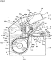
- FIGS. 1 and 2 are configuration views depicting an example of a binding device in accordance with a first embodiment.
- FIG. 1 depicts an internal configuration of a binding device 1A
- FIG. 2 depicts an external configuration of the binding device 1A.
- FIG. 3 is a configuration view depicting an example of a piece having bound a sheet bundle
- FIG. 4 is a configuration view depicting an example of the piece.
- the binding device 1A of the first embodiment is a device configured to bind a sheet bundle 10 by winding a piece 2, which is a disposable, to the sheet bundle 10 having a plurality of stacked sheets.
- the sheet bundle 10 is formed by stacking sheets such as documents, sheet-like members formed of a metal or resin material, and the like.
- One side of the piece 2 is wound from a lower surface, which is-one surface of the sheet bundle 10, to an end portion 10a-side of the sheet bundle 10. Also, the other side of the piece 2 is wound through a through-hole 10b formed in the sheet bundle 10. The respective end portions of the piece 2 are bonded to an upper surface, which is the other surface of the sheet bundle 10, so that the piece binds the sheet bundle 10.
- the piece 2 has a rectangular shape, for example.
- One surface 2a of the piece 2 is a planar surface, and the other surface 2b is provided with an adhesive layer 3.
- a plurality of the pieces 2 is temporarily bonded to a long release paper 4 in a longitudinal direction, for example. Thereby, even when the piece is used after it has been left for a long time, it is possible to prevent an adhesive force of the adhesive layer 3 from being lowered.
- the piece 2 is made of an easily bendable non-metal material having a thin foil shape.
- a tape 5 consisting of the piece 2 and the release paper 4 is wound into a roll shape and is accommodated in the binding device 1A, as a roll body, for example.
- the piece 2 and the release paper 4 are formed with a plurality of engaging holes 6, in which a mechanism configured to convey the tape 5 is to be engaged, with a predetermined interval in the longitudinal direction.
- the binding device 1A is configured to preliminarily shape the piece 2 by relative movement between the sheet bundle 10 and the piece 2 resulting from movement of the sheet bundle 10.
- the binding device includes a base unit 11A and a handle unit 12 configured to be rotatable relative to the base unit 11A.
- the binding device 1A includes a holding unit 20 configured to hold and move the sheet bundle 10, which is a binding target, a binding unit 40 configured to shape the piece 2 in corporation with the holding unit 20 and to bind the sheet bundle 10 with the piece 2, a conveyor unit 50 as an example of the piece conveyor unit configured to convey the tape 5 in corporation with the holding unit 20, and a cassette storage unit 60A to which a cassette 8 having a roll body 7 of the tape 5 accommodated therein is to be detachably mounted.
- the handle unit 12 is an example of the operation member.
- a shaft 12m provided at one end portion-side of the handle unit 12 is engaged with a shaft support part 11m provided at one end portion-side of the base unit 11A.
- the handle unit 12 is attached to the base unit 11A so that one end portion-side thereof can rotate about the shaft 12m, which is a support point, and the other end portion-side becomes a free end.
- the handle unit 12 is provided with a gripping part 12a for gripping and operating the binding device 1A. When operating the binding device 1A, it is possible to operate the same with gripping the gripping part 12a.
- the binding device 1A is configured so that when the free end-side of the handle unit 12 is operated, the handle unit 12 is rotated about the shaft 12m serving as a support point and the rotating operation of the handle unit 12 is transmitted to the binding unit 40 to operate the binding unit 40, as described later.
- a side at which the base unit 11A is provided is defined as a lower side in an upper and lower direction, such as a lower surface, a lower side, a downward side and the like, and a side at which the handle unit 12 is defined as an upper side in the upper and lower direction, such as an upper surface, an upper side, an upward side and the like.
- the free end-side of the handle unit 12 is defined as a front side in a front and rear direction, such as a front surface, a front side, a forward side and the like, and a side at which the shaft 12m is defined as a rear side in the front and rear direction, such as a rear surface, a rear side, a rearwards side and the like.
- the base unit 11A has a main frame body 11e and a lower frame body 11f.
- the base unit 11A is provided with the shaft support part 11m at a rear and upper part of the main frame body 11e.
- the base unit 11A is attached with the lower frame body 11f to be rotatable about a shaft 11g provided at a rear and lower part of the main frame body 11e and serving as a support point.
- the base unit 11A is configured so that when the lower frame body 11f is rotated in an arrow J 1 direction and an arrow J 2 direction, the lower frame body 11f is opened rearwards and a lower part of the base unit 11A is opened and closed.
- the base unit 11A has a movement support part 11n configured to moveably support the holding unit 20 and provided at the main frame body 11e.
- the movement support part 11n is provided at a front and upper surface-side of the base unit 11A with facing the free end-side of the handle unit 12 and is configured as a groove part provided along the front and rear direction and configured to guide movement of the holding unit 20 in an arrow F direction and an arrow R direction.
- the holding unit 20 is an example of the placement unit, is attached to a front and upper surface of the base unit 11A so as to be moveable in the front and rear direction by the movement support part 11n, and is configured to be moveable between an inserting/drawing position of the sheet bundle 10 located below the free end-side of the handle unit 12 and a binding position located below the binding unit 40.
- the holding unit 20 includes a tray 23 on which the sheet bundle 10, which is a binding target, is to be placed, and a pushing member 24 rotatably attached to the tray 23 and configured to push the sheet bundle 10 to the tray 23 by a rotation operation.
- the holding unit 20 since the holding unit 20 relates to a partial preliminary shaping of an operation of once winding the piece 2 to the sheet bundle 10, the holding unit configures the preliminary shaping unit. Also, since the holding unit 20 relates to a part of an operation of conveying the tape 5, the holding unit configures the conveying unit.
- the tray 23 is configured to have a rectangular flat plate shape in conformity to the shape of the base unit 11A, and has a placement part 23a on which the sheet bundle 10 is to be placed, and an engaging guide part 23b to be engaged with the movement support part 11n of the base unit 11A.
- the engaging guide part 23b has a shape protruding downwards from a lower surface of the placement part 23a, and is configured to engage with the movement support part 11n of the base unit 11A. Thereby, the holding unit 20 can move between the inserting/drawing position and the binding position as the engaging guide part 23b is guided to the movement support part 11n.
- the holding unit 20 is provided with a rotary shaft 23c configured to rotatably support the pushing member 24 at a rear end portion of the placement part 23a.
- a rear end-side of the placement part 23a is provided with a cutout part 23d having a rectangular shape at a substantial center in a width direction.
- the cutout part 23d is configured by providing the placement part 23a with an opening, in which the piece 2 configured to bind the sheet bundle 10 and a cutting blade 44 (which will be described later) of the binding unit 40 can be introduced when the holding unit 20 is moved to the binding position, while avoiding the adhesion position of the piece 2.
- the holding unit 20 has a holding claw 23e configured to hold the release paper 4.
- the holding claw 23e is an example of the conveying unit, is provided at the engaging guide part 23b with facing a conveyance path of the release paper 4, and moves in the arrow F direction and the R direction when the holding unit 20 moves.
- the holding claw 23e is configured to be rotatable by a rotation operation about a shaft 23f serving as a support point, which is provided at an upstream side with respect to the conveying direction in which the release paper 4 is to be drawn out, and is urged in the direction of the release paper 4 by a spring 23g.
- the holding claw 23e When the holding claw 23e is moved in the arrow R direction by an operation of moving the holding unit 20 from the inserting/drawing position to the binding position, the holding claw rotates about the shaft 23f serving as a support point in an arrow G 1 direction, against the spring 23g, and retreats from the conveyance path of the release paper 4. Thereby, the holding claw is not engaged with the engaging hole 6 of the release paper 4, so that the tape 5 and the release paper 4 are not reversely conveyed by the operation of moving the holding unit 20 from the inserting/drawing position to the binding position.
- the holding claw 23e when the holding claw 23e is moved in the arrow F direction by an operation of moving the holding unit 20 from the binding position to the inserting/drawing position, the holding claw rotates about the shaft 23f serving as a support point in an arrow G 2 direction by a force of the spring 23g and protrudes into the conveyance path of the release paper 4. Thereby, the holding claw 23e is engaged with the engaging hole 6 of the release paper 4, so that the tape 5 and the release paper 4 are drawn out by the operation of moving the holding unit 20 from the binding position to the inserting/drawing position.
- the pushing member 24 is rotatably supported at a rear end-side by the rotary shaft 23c, and is configured to rotate in an arrow H 1 direction and an arrow H 2 direction with respect to the tray 23, thereby opening and closing a front side of the tray 23.
- the pushing member 24 is made of an elastic material, and elastic pieces 24b of which a front side is configured as a base end are integrally provided.
- the elastic pieces 24b are provided by two members protruding from the pushing member 24 so that they are positioned at right and left sides of the cutout part 23d of the placement part 23a.
- a rear end-side of the elastic piece is a free end and is bent towards the tray 23.
- the elastic pieces 24b are contacted at rear ends thereof to the tray 23 and are configured to raise and keep the entire pushing member 24.
- the pushing member 24 is provided so that a binding position of the sheet bundle 10 is not to deviate from the tray 23.
- the pushing member 24 is not necessarily provided.
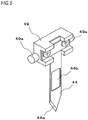
- FIG. 5 is a perspective view depicting a driving mechanism of the cutting blade.
- a mechanism configured to operate the binding unit 40 and the cutting blade 44 by the handle unit 12 is described with reference to the respective drawings.
- the binding unit 40 has a driving member 41 provided on an inner and lower surface of the handle unit 12. Also, the binding unit 40 has a guide lever 42 configured to move in an upper and lower direction by displacement of the driving member 41, a pressing lever 43 configured to press the piece 2 configured to bind the sheet bundle 10, and a cutting blade 44 configured to penetrate the sheet bundle 10, which are provided in a component arranging part 27.
- the component arranging part 27 is integrally provided with the base unit 11A, and an entrance groove 28 in which the holding unit 20 moving to the binding position is to be introduced is provided on a moving path of the holding unit 20. Also, the component arranging part 27 and the base unit 11A have a piece standby part 28a at which the piece 2 released from the release paper 4 is to stand by and which is provided on a moving path of the sheet bundle 10 held by the holding unit 20 to be inserted into the entrance groove 28.
- the entrance groove 28 is an opening provided with being spaced between the base unit 11A and the component arranging part 27.
- the pushing member 24 When the holding unit 20 is introduced into the entrance groove, the pushing member 24 is pressed in an arrow H 1 direction of coming close to the tray 23, so that the sheet bundle 10 is interposed and held between the tray 23 and the pushing member 24.
- the holding unit 20, the entrance groove 28 and the pressing lever 43 configure the preliminary shaping unit configured to preliminarily shape the piece 2 by the relative rotation between the sheet bundle 10 and the piece 2 resulting from the movement of the holding unit 20.
- the binding unit 40 has the pressing lever 43 and the cutting blade 44, which are provided above the entrance groove 28, and the driving member 41 configured to transmit the movement of the handle unit 12 to the pressing lever 43 via the cutting blade 44 and the guide lever 42 and having first guide holes 41a and second guide holes 41b.
- the first guide hole 41a is configured as a long hole and a convex portion 42a of the guide lever 42 is engaged thereto.
- the second guide hole 41b is configured as a long hole and a convex portion 49a of an attaching member 49 ( FIG. 5 ) having the cutting blade 44 attached thereto is engaged to the second guide hole.
- the guide lever 42 is configured so that it is to be guided and moved in the upper and lower direction by the component arranging part 27.
- an elastic member such as a coil spring 45 is wound and inserted.
- the coil spring 45 configures a so-called return spring of the handle unit 12, and a lower end portion thereof is received at the base unit 11A by a receiving part 46 of the component arranging part 27.
- an upper end portion of the coil spring 45 is received at the handle unit 12 by the convex portion 42a of the guide lever 42 engaged to the first guide hole 41 a of the driving member 41.
- the handle unit 12 is urged in an arrow U direction of separating from the base unit 11A by the coil spring 45. Also, when the handle unit 12 is pushed in an arrow D direction, the coil spring 45 is contracted and the guide lever 42 is linearly moved in the arrow D direction.
- the first guide hole 41a is configured as a long hole, so that the convex portion 42a can move along the first guide hole 41a of which a locus of displacement is a circular arc shape about the shaft 12m and the guide lever 42 is linearly moved without a locus of displacement of the convex portion 42a forming into a circular arc shape.
- the pressing lever 43 is provided in front of the guide lever 42.
- the pressing lever 43 has a pressing part 43a configured to press and bond the piece 2 to the sheet bundle 10.
- the pressing lever 43 is wound with a pressing spring 47 consisting of an elastic member such as a coil spring.
- the pressing spring 47 has one end engaged to the pressing part 43a and the other end engaged to the moving member 48 configured to move in conjunction with the guide lever 42.
- the cutting blade 44 is provided in front of the pressing lever 43. As shown in FIG. 5 , the cutting blade 44 is formed with an insertion hole 44b, which is provided above a blade part 44a and the piece 2 is to be inserted therein. The cutting blade 44 is attached to the attaching member 49, and the attaching member 49 is connected to the guide lever 42.
- the blade part 44a of the cutting blade 44 which is provided at a tip end, does not protrude downwards from the entrance groove 28.
- a height and a moving amount of the blade part 44a are set so that when the handle unit 12 is pressed in the arrow U direction, the blade part penetrates the sheet bundle 10 pressed by the pressing part 43a of the pressing lever 43.
- the convex portions 49a protrude laterally from right and left sides of the attaching member 49 having the cutting blade 44.
- Each convex portion 49a is engaged to the second guide hole 41 b of the driving member 41.
- the second guide hole 41b is configured as a long hole, so that the convex portion 49a can move along the second guide hole 41b of which a locus of displacement is a circular arc shape about the shaft 12m and the cutting blade 44 is linearly moved without a locus of displacement of the convex portion 49a forming a circular arc shape.
- the handle unit 12 when the handle unit 12 is pressed down in the arrow D direction, the handle unit 12 is rotated above the shaft 12m serving as a support point in the arrow D direction, so that the convex portions 49a configured to drive the cutting blade 44 by the second guide holes 41b of the driving member 41 are pressed and the cutting blade 44 is thus moved in the arrow D direction. Thereby, the cutting blade 44 penetrates the sheet bundle 10.
- the handle unit 12 when the handle unit 12 is pushed up in the arrow U direction, the handle unit 12 is rotated above the shaft 12m serving as a support point in the arrow U direction, so that the convex portions 49a configured to drive the cutting blade 44 by the second guide holes 41b of the driving member 41 are pushed up and the cutting blade 44 is thus moved in the arrow U direction. Thereby, the cutting blade 44 having penetrated the sheet bundle 10 is pulled out. During the pulling-out operation of the cutting blade 44, the piece 2 held by the cutting blade 44 is pulled out to the surface-side of the sheet bundle 10, in succession to the cutting blade 44, as described later.
- a pressing roller 56 configuring a part of the binding unit 40 is described.
- the pressing roller 56 is provided in front of the cutting blade 44.
- the pressing roller 56 is urged downwards by an elastic member such as a coil spring 57, and presses the piece 2 having bound the sheet bundle 10 when the holding unit 20 is moved between the binding position and the inserting/drawing position.
- the conveyor unit 50 is an example of the conveying unit, and has a first guide configuring member 50a provided at the main frame body 11e of the base unit 11A and a second guide configuring member 50b provided at the lower frame body 11f with facing the first guide configuring member 50a, which members configure a conveyance path 51 of the tape 5 before the piece 2 to be carried by the operation of the holding unit 20 is to be released and the release paper 4 from which the piece 2 has been released.
- the conveyor unit 50 has a first roller 52a configured to guide the tape 5 pulled out from the cassette 8 accommodated in the cassette storage unit 60A and a second roller 52b configured to face more downwards than a horizontal direction on the conveyance path of the tape 5 at a downstream side of the first roller 52a, and configures a bent conveyance path. Also, the conveyor unit 50 has an engaging claw 52c configured to hold the release paper 4 and a retreat part 52d configured to retreat the release paper 4 held with the engaging claw 52c.
- the first roller 52a of the conveyor unit 50 is provided at the first guide configuring member 50a. Also, the second roller 52b and the engaging claw 52c of the conveyor unit 50 are provided at the second guide configuring member 50b. In addition, the retreat part 52d of the conveyor unit 50 is configured in a space between the first guide configuring member 50a and the second guide configuring member 50b.
- the conveyor unit 50 is configured to bend the conveyance path to an acute angle by the second roller 52b, thereby configuring a release part 52e configured to release the piece 2 from the tape 5 by using rigidness of the piece 2.
- the tape 5 pulled out from the cassette 8 accommodated in the cassette storage unit 60A is conveyed upwards with being guided to the first roller 52a.
- the tape 5 is guided to the second roller 52b and is bent to an acute angle.
- the release paper 4 is bent to an acute angle at the release part 52e, so that only the piece 2 temporarily attached to the release paper 4 travels straight upwards and the piece 2 is straightly released by about a half from the release paper 4 without being bent.
- the piece 2 released from the release paper 4 waits for the sheet bundle 10 with the adhesive layer 3 shown in FIG. 4 facing towards the sheet bundle 10 that is being introduced with being held by the holding unit 20.
- the release paper 4 downstream of the second roller 52b is conveyed to the front of the base unit 11A and is discharged.
- the engaging claw 52c is provided downstream of the second roller 52b, protrudes to the conveyance path 51 with being inclined forward, and is engaged with the engaging hole 6 of the release paper 4.
- the retreat part 52d is configured by providing a space, in which the release paper 4 is to be introduced, at a position facing the engaging claw 52c.
- the holding claw 23e is moved in the arrow R direction and the tape 5 and the release paper 4 are thus applied with a force in a reverse conveying direction, the engaging claw 52c is engaged with the engaging hole 6 of the release paper 4, so that the tape 5 and the release paper 4 are not reversely conveyed.
- the holding claw 23e is moved in the arrow F direction and the tape 5 and the release paper 4 are thus applied with a force in a forward conveying direction, the engaging claw 52c is disengaged from the engaging hole 6 of the release paper 4, the release paper 4 is introduced into the retreat part 52d and the tape 5 and the release paper 4 can be conveyed in the forward direction.
- the engaging hole 6 of the release paper 4 is engaged with the engaging claw 52c.
- the cassette storage unit 60A is an example of the storage unit, and is provided at a lower part of the device main body 110A having the base unit 11A and the handle unit 12.
- the cassette storage unit 60A is provided at a rear and lower part of the base unit 11A, in the first embodiment.
- the roll body 7 of which the tape 5 is wound in an involution form where the surface having the piece 2 bonded thereto faces towards an inner side is accommodated, and the tape 5 is to be pulled out from a drawing port 8a.
- the cassette 8 is accommodated in a vertical direction so that a circumferential direction of the roll body 7 becomes a vertical direction, and the tape 5 pulled out from the drawing port 8a of the cassette 8 is guided to the conveyance path 51 from the lower part of the conveyor unit 50.
- an external shape of the cassette 8 is configured so that it does not protrude rearwards beyond the rear end of the handle unit 12.
- the cassette storage unit 60A is provided at a part of the device main body 110A, which is at the rear of the gripping part 12a of the handle unit 12, i.e., at the base unit 11A in the first embodiment. Also, the cassette storage unit 60A is provided at a part facing the cutting blade 44 with the sheet bundle 10, which is to be placed as described later by the holding unit 20, being interposed therebetween. Also, the cassette storage unit 60A is provided at a part of a side at which the drawing port 8a of the cassette 8 faces the cutting blade 44 via the conveyor unit 50 being interposed therebetween. Also, the cassette storage unit 60A is provided at a part of a side that faces the gripping part 12a of the handle unit 12 via the sheet bundle 10, which is to be placed by the holding unit 20, being interposed therebetween.
- the cassette 8 is accommodated in the cassette storage unit 60A so that the drawing port 8a is positioned just below the conveyance path reaching the release part 52e, i.e., so that the drawing port 8a faces upwards, in the first embodiment, and a part at which the tape 5 is to be pulled out from the drawing port 8a is provided below the conveyance path 51. Thereby, the conveyance path from the drawing port 8a to the release part 52e is substantially linear.
- the release part 52e is configured to bend the conveyance path to an acute angle with the second roller 52b, thereby releasing the piece 2 from the tape 5 by using the rigidness of the piece 2.
- the conveyance path reaching the release part 52e is made to be linear, so that the load is reduced upon the conveying of the tape 5 and the release paper 4.
- the accommodation position of the cassette 8 is set in conformity to the position of the shaft 11g of the lower frame body 11f. Thereby, the cassette storage unit is opened and closed by the rotation operation of the lower frame body 11f about the shaft 11g serving as a support point.
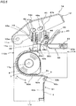
- FIG. 6 illustrates an opened and closed state of the cassette storage unit. In the below, operations of attaching and detaching the cassette 8, the tape 5 and the release paper 4 in the binding device 1A are described.
- the second guide configuring member 50b is opened downwards with respect to the first guide configuring member 50a, and the second roller 52b and the engaging claw 52c are retreated from the conveyance path, so that the conveyance path 51 is exposed.
- the cassette 8 is held in the cassette storage unit 60A. Also, when the lower frame body 11f is closed, the first guide configuring member 50a and the second guide configuring member 50b face each other and form the conveyance path 51 and the tape 5 and the release paper 4 are mounted to a predetermined conveyance path.
- the cassette storage unit 60A is provided at the lower part of the base unit 11A and the lower frame body 11f is configured to be openable and closable, so that the cassette storage unit 60A and the conveyance path 51 can be opened and closed. Therefore, at the state where the lower frame body 11f is opened, the entire conveyance path of the tape 5 and the release paper 4, including parts to be pulled out from the cassette storage unit 60A, is exposed, as shown in FIG. 6 . Thereby, it is possible to easily attach and detach the tape 5 and the release paper 4.
- the roll body 7 is accommodated in the cassette 8.
- a configuration where the cassette storage unit 60A is formed in conformity to the roll body 7 and the roll body 7 can be directly accommodated in the cassette storage unit 60A is also possible.
- FIG. 7 illustrates an outline of an operation of binding the sheet bundle with the piece
- FIGS. 8 to 13 illustrate an example of an operation of the binding device of the first embodiment.
- an operation of binding the sheet bundle 10 with the piece 2 in the binding device 1A of the first embodiment is described.
- the handle unit 12 is not operated and the cutting blade 44 is retreated to a standby position above the entrance groove 28. Also, the pushing member 24 is rotated in the arrow H 2 direction, so that the holding unit 20 is opened relative to the tray 23 and is located at the inserting/drawing position Pp1.
- the pushing member 24 and the elastic piece 24b are elastically deformed in accordance with a thickness of the sheet bundle 10 and is temporarily pressed to the placement part 23a by the elastic pieces 24b.
- the holding unit 20 holding the sheet bundle 10 is moved from the inserting/drawing position Pp1 in the arrow R direction, so that the end portion 10a of the sheet bundle 10 is contacted to the piece 2 standing by at the piece standby part 28a.
- the sheet bundle 10 and the piece 2 pushed to the sheet bundle 10 are interposed between the pressing part 43a of the pressing lever 43 and the entrance groove 28.
- the piece 2 is introduced into an unevenness shape formed by a combination of the pressing part 43a of the pressing lever 43, the entrance groove 28 and the end portion 10a of the sheet bundle 10, as shown in FIG. 7B .
- the piece 2 is preliminarily shaped in conformity to the shape formed by the end portion 10a of the sheet bundle 10, the pressing part 43a of the pressing lever 43 and the entrance groove 28 and is released from the release paper 4.
- the tape 5 and the release paper 4 are applied with a force in the reverse conveying direction, so that the engaging claw 52c is engaged with the engaging hole 6 of the release paper 4.
- the holding claw 23e is rotated above the shaft 23f serving as a support point in the arrow G 1 direction, against the spring 23g, and is retreated from the conveyance path of the release paper 4. Thereby, the holding claw 23e is disengaged from the engaging hole 6 of the release paper 4, and the tape 5 and the release paper 4 are not reversely conveyed with the operation of moving the holding unit 20 from the inserting/drawing position Pp1 to the binding position Pp2.
- the convex portion 49a configured to drive the cutting blade 44 by the second guide hole 41b of the driving member 41 is pressed with the rotation operation of the handle unit 12 about the shaft 12m serving as a support point in the arrow D direction, so that the cutting blade 44 is moved in the arrow D direction.
- the cutting blade 44 penetrates the sheet bundle 10 at the state where the sheet bundle 10 is pressed by the pressing lever 43, as shown in FIG. 7C .
- a free end of the back surface of the sheet bundle 10 which is a part of the piece 2 not bonded to the sheet bundle 10, is introduced into the insertion hole 44b of the cutting blade 44.
- the convex portion 49a configured to drive the cutting blade 44 by the second guide hole 41b of the driving member 41 is pushed up with the rotation operation of the handle unit 12 about the shaft 12m serving as a support point in the arrow U direction, so that the cutting blade 44 is moved in the arrow U direction. Then, as shown in FIG. 7D , as the cutting blade 44 returns, i.e., the cutting blade 44 having penetrated the sheet bundle 10 is pulled out, the free end of the piece 2 inserted in the insertion hole 44b is pulled out to the surface-side of the sheet bundle 10, in succession to the cutting blade 44.
- the holding unit 20 holding the sheet bundle 10 is moved in the arrow F direction.
- the piece 2 inserted in the sheet bundle 10 is interposed between the sheet bundle 10 and the pressing roller 56, as shown in FIG. 7E .
- the piece 2 is pressed to the sheet bundle 10 by the pressing roller 56, so that the piece 2 is bonded to the sheet bundle 10 and is finally shaped.
- the holding claw 23e is moved in the arrow F direction, so that the holding claw is rotated about the shaft 23f serving as a support point in the arrow G 2 direction by the force of the spring 23g and protrudes to the conveyance path of the release paper 4.
- the holding claw 23e is engaged with the engaging hole 6 of the release paper 4, and the force of moving the release paper 4 in the arrow F direction is applied.
- the engaging claw 52c is disengaged from the engaging hole 6 of the release paper 4 and the release paper 4 is introduced into the retreat part 52d.
- the tape 5 and the release paper 4 are pulled out by a length of one piece 2 by the operation of moving the holding unit 20 from the binding position Pp2 to the inserting/drawing position Pp1.
- the engaging claw 52c is engaged with the engaging hole 6 of the release paper 4.
- the binding device 1A has the configuration where the handle unit 12 is displaced by the rotation operation about the shaft 12m serving as a support point.
- the cassette storage unit 60A is provided at the part of the device main body 110A, which faces the gripping part 12a of the handle unit 12 via the sheet bundle 10, which is to be placed by the holding unit 20m, being interposed therebetween, in the first embodiment, the part at the rear of the gripping part 12a of the handle unit 12, i.e., the part of the side that faces the cutting blade 44 via the sheet bundle 10 being interposed therebetween. Therefore, any problem is not caused when gripping the gripping part 12a of the handle unit 12.
- the size of the device main body 110A in the front and rear direction can be made small, and the external shape of the cassette 8 to be accommodated in the cassette storage unit 60A is configured so that the cassette does not protrude rearwards beyond the rear end of the handle unit 12, in the first embodiment. Therefore, even when the device is used on a desk, it is possible to reduce a provision area thereof.
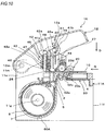
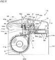
- FIG. 14 is a configuration view depicting an example of a binding device in accordance with a second embodiment.
- a binding device 1B of the second embodiment is configured to accommodate the cassette 8 at a front and lower part.
- the equivalent configurations to the binding device 1A of the first embodiment are denoted with the same reference numerals and the detailed descriptions thereof are omitted.
- the binding device 1B has a cassette storage unit 60B configured to detachably mount the cassette 8 thereto and provided at a lower part of a device main body 110B having a base unit 11B and the handle unit 12, in the second embodiment, at a front and lower part of the base unit 11B, which is an opposite side to the shaft 12m about which the handle unit 12 is to rotate.
- the base unit 11B has a main frame body 11h and a lower frame body 11i.
- the base unit 11B has the shaft support part 11m provided at a rear and upper part of the main frame body 11h. Also, the base unit 11B is attached so that the lower frame body 11i can rotate about a shaft 11j provided in front of the main frame body 11h and serving as a support point.
- the base unit 11B is configured so that the lower frame body 11i is to be opened forward and the lower part of the base unit 11B can be opened and closed by a rotation operation of the lower frame body 11i in an arrow K 1 direction and an arrow K 2 direction.
- the handle unit 12 is provided with the gripping part 12a for gripping and operating the binding device 1B, and when operating the binding device 1B, it is possible to operate the same with gripping the gripping part 12a.
- the conveyor unit 50 has a configuration where the main frame body 11h of the base unit 11B is provided with the first guide configuring member 50a and the first guide configuring member 50a is provided with the first roller 52a. Also, the conveyor unit 50 has a configuration where the lower frame body 11i of the base unit 11 B is provided with the second guide configuring member 50b and the second guide configuring member 50b is provided with the second roller 52b and the engaging claw 52c.
- the cassette storage unit 60B is an example of the storage unit, and is provided at a part of the device main body 110B, which faces the shaft 12m of the rotation operation of the handle unit 12 via the cutting blade 44 being interposed therebetween, in the second embodiment, at a front and lower part of the base unit 11B.
- the cassette storage unit 60B is configured so that the tape 5 provided at the lower frame body 11i and pulled out from the drawing port 8a of the cassette 8 is to be guided to the conveyance path 51 from the lower part of the conveyor unit 50 and the external shape of the cassette 8 to be accommodated therein does not protrude forward beyond a front end of the main frame body 11h, in the second embodiment.
- the cassette 8 is accommodated so that the drawing port 8a is positioned just below the conveyance path reaching the release part 52e, in the second embodiment, so that the drawing port 8a faces upwards, and a part at which the tape 5 is to be pulled out from the drawing port 8a is provided below the conveyance path 51, like the binding device 1A of the first embodiment.
- the cassette storage unit 60B is provided at a part of the device main body 110B, in front of the gripping part 12a of the handle unit 12. Also, the cassette storage unit 60B is provided at a part that faces the cutting blade 44 via the sheet bundle 10, which is to be placed by the holding unit 20, being interposed therebetween. Also, the cassette storage unit 60B is provided at a part of a side at which the drawing port 8a of the cassette 8 faces the cutting blade 44 via the conveyor unit 50 being interposed therebetween. Also, the cassette storage unit 60B is provided at a part of a side that faces the gripping part 12a of the handle unit 12 via the sheet bundle 10, which is to be placed by the holding unit 20, being interposed therebetween.
- the cassette storage unit 60B is provided at the lower frame body 11i, so that it can be opened and closed by the rotation operation of the lower frame body 11i about the shaft 11j serving as a support point.
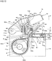
- FIG. 15 illustrates an opened and closed state of the cassette storage unit. In the below, operations of attaching and detaching the cassette 8, the tape 5 and the release paper 4 in the binding device 1B are described.
- the cassette storage unit 60B is opened. Thereby, the cassette 8 can be attached and detached from the lower side of the base unit 11B.
- the second guide configuring member 50b is opened downwards with respect to the first guide configuring member 50a, and the second roller 52b and the engaging claw 52c are retreated from the conveyance path, so that the conveyance path 51 is exposed.
- the cassette 8 is mounted to a predetermined position, the first guide configuring member 50a and the second guide configuring member 50b face each other and form the conveyance path 51, and the tape 5 and the release paper 4 are mounted to a predetermined conveyance path.
- the cassette storage unit 60B is provided at the lower part of the base unit 11B and the lower frame body 11i is configured to be openable and closable, so that the cassette storage unit 60B and the conveyance path 51 can be opened and closed. Therefore, at the state where the lower frame body 11i is opened, the entire conveyance path of the tape 5 and the release paper 4, including parts to be pulled out from the cassette storage unit 60B, is exposed, as shown in FIG. 15 . Thereby, it is possible to easily attach and detach the tape 5 and the release paper 4.
- the roll body 7 is accommodated in the cassette 8.
- a configuration where the cassette storage unit 60B is formed in conformity to the roll body 7 and the roll body 7 can be directly accommodated in the cassette storage unit 60B is also possible.
- the binding device 1B also has the configuration where the handle unit 12 is displaced by the rotation operation about the shaft 12m serving as a support point.
- the cassette storage unit 60B is provided at the part of the device main body 110B, which faces the gripping part 12a of the handle unit 12 via the sheet bundle 10, which is to be placed by the holding unit 20m, being interposed therebetween, in the second embodiment, the part in front of the gripping part 12a of the handle unit 12, i.e., the part of the side that faces the cutting blade 44 via the sheet bundle 10 being interposed therebetween. Therefore, any problem is not caused when gripping the gripping part 12a of the handle unit 12.
- the size of the device main body 110B in the front and rear direction can be made small, and the external shape of the cassette 8 to be accommodated in the cassette storage unit 60B is configured so that the cassette does not protrude rearwards beyond the rear end of the handle unit 12, in the second embodiment. Therefore, even when the device is used on a desk, it is possible to reduce a provision area thereof.
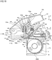
- FIG. 16 is a configuration view depicting a modified embodiment of the binding device in accordance with the second embodiment.
- the equivalent configurations to the binding device 1B of the second embodiment are denoted with the same reference numerals and the detailed descriptions thereof are omitted.
- the handle unit 12 is provided with a first gripping part 12a 1 for gripping and operating the binding device 1B 1 .
- a second gripping part 11d 1 for gripping and operating the binding device 1B 1 is provided by cutting a rear and lower part of the main frame body 11h, which is a non-formation position of the cassette storage unit 60B.
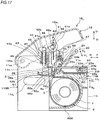
- FIG. 17 is a configuration view depicting another modified embodiment of the binding device in accordance with the second embodiment.
- the equivalent configurations to the binding device 1B of the second embodiment are denoted with the same reference numerals and the detailed descriptions thereof are omitted.
- the handle unit 12 is provided with a first gripping part 12a 1 for gripping and operating the binding device 1B 2 .
- a second gripping part 11d 2 for gripping and operating the binding device 1B 2 is provided by forming a long opening in which a finger is to enter at a rear and lower part of the main frame body 11h, which is a non-formation position of the cassette storage unit 60B.
- the cassette storage unit 60B is provided at the part of the device main body 110B in front of the first gripping part 12a 1 of the handle unit 12. Therefore, a degree of freedom of the shape of the base unit 11B increases, so that it is possible to form a shape more appropriate to the gripping.
- FIGS. 18 and 19 are configuration views depicting an example of a binding device in accordance with a third embodiment.
- FIG. 18 is a side view depicting an internal configuration of the binding device 1C
- FIG. 19 is a plan view of the binding device 1C.
- a binding device 1C of the third embodiment is configured to accommodate the cassette 8 in a front and lower part with keeping the same in the horizontal direction.
- the equivalent configurations to the binding device 1A of the first embodiment are denoted with the same reference numerals and the detailed descriptions thereof are omitted.
- the binding device 1C has a cassette storage unit 60C configured to detachably mount the cassette 8 thereto and provided at a lower part of a device main body 110C having a base unit 11C and the handle unit 12, in the third embodiment, at a front and lower part of the base unit 11C, which is an opposite side to the shaft 12m about which the handle unit 12 is to rotate.
- the base unit 11C has a main frame body 11p and a lower frame body 11q.
- the base unit 11C has the shaft support part 11m provided at a rear and upper part of the main frame body 11p. Also, the base unit 11C is attached so that the lower frame body 11q can rotate about a shaft 11r provided in front of the main frame body 11p and serving as a support point.
- the base unit 11C is configured so that the lower frame body 11q is to be opened forward and the lower part of the base unit 11C can be opened and closed by a rotation operation of the lower frame body 11 q in the arrow K 1 direction and the arrow K 2 direction.
- the handle unit 12 is provided with the first gripping part 12a 1 for gripping and operating the binding device 1C.
- the binding device 1C is provided with a second gripping part 12d 3 for gripping and operating the binding device 1C.
- the conveyor unit 50 has a configuration where the main frame body 11p of the base unit 11C is provided with the first guide configuring member 50a and the first guide configuring member 50a is provided with the first roller 52a. Also, the conveyor unit 50 has a configuration where the lower frame body 11q of the base unit 11C is provided with the second guide configuring member 50b and the second guide configuring member 50b is provided with the second roller 52b and the engaging claw 52c.
- the cassette storage unit 60B is opened and the cassette 8 can be attached and detached.
- the second guide configuring member 50b is opened downwards with respect to the first guide configuring member 50a and the conveyance path 51 is exposed, so that the tape 5 and the release paper 4 can be attached and detached.
- the cassette 8 is mounted to a predetermined position, the first guide configuring member 50a and the second guide configuring member 50b face each other and form the conveyance path 51 and the tape 5 and the release paper 4 are mounted to a predetermined conveyance path.
- the cassette 8 is accommodated in the horizontal direction so that the circumferential direction of the roll body 7 becomes the horizontal direction, and the tape 5 pulled out from the drawing port 8a of the cassette 8 is guided to the conveyance path 51 from the lower part of the conveyor unit 50.
- an external shape of the cassette 8 is configured so that it does not protrude forward beyond the front end of the main frame body 11h. That is, the cassette storage unit 60C is provided at a part of the device main body 110B, which faces the shaft 12m of the rotation operation of the handle unit 12 via the cutting blade 44 being interposed therebetween.
- a part at which the tape 5 is to be pulled out from the drawing port 8a is provided below the conveyance path 51, and the conveyance path is bent so that the tape 5, which is to be pulled out from the drawing port 8a of the cassette 8 in the horizontal direction, is to be conveyed in the vertical direction at the release part 52e, as shown in FIG. 19 .
- the cassette storage unit 60C is provided at a part of the device main body 110C, in front of the first gripping part 12a 1 of the handle unit 12 or the second gripping part 11d 3 of the base unit 11C. Also, the cassette storage unit 60C is provided at a part of a side that faces the cutting blade 44 via the sheet bundle 10, which is to be placed by the holding unit 20, being interposed therebetween. Also, the cassette storage unit 60C is provided at a part of a side at which the drawing port 8a of the cassette 8 faces the cutting blade 44 via the conveyor unit 50 being interposed therebetween. Also, the cassette storage unit 60C is provided at a part of a side that faces the first gripping part 12a 1 of the handle unit 12 via the sheet bundle 10, which is to be placed by the holding unit 20, being interposed therebetween.
- the cassette 8 is attached in the horizontal direction, so that it is possible to suppress a size in a height direction, too. Thereby, a degree of freedom of the shape of the base unit 11C increases, so that it is possible to form a shape more appropriate to the gripping. Also, it is possible to make the size of the device main body 110C in the front and rear direction small, and even when the device is used on a desk, it is possible to reduce a provision area thereof.
- the piece 2 is preliminarily shaped by the relative movement between the sheet bundle 10 and the piece 2 resulting from the movement of the sheet bundle 10, and the operation of the holding unit 20 moving the sheet bundle 10 may be performed in conjunction with the operation of the handle unit 12. Also, the piece 2 may preliminarily shaped by the relative movement between the sheet bundle 10 and the piece 2 resulting from movement of the piece 2, without moving the sheet bundle 10.
- the operation member configured to move the cutting blade 44 and the pressing lever 43 by the linear movement may be provided just above the cutting blade 44 and the pressing lever 43.
- FIGS. 20 and 21 are configuration views depicting an example of a binding device in accordance with a fourth embodiment.
- a binding device 1D has a base unit 111 and a handle unit 122 provided to be rotatable relative to the base unit 111.
- the base unit 111 has a cassette storage unit 111a, to which the cassette 8 having the roll body 7 of the tape 5 accommodated therein is to be detachably mounted, at a front and lower part. Also, the base unit 111 has an entrance groove 111b in which the sheet bundle 10 is to be inserted. Also, although not shown, the base unit 111 has the conveyor unit configured to convey the tape 5 and the release paper 4 pulled out from the cassette 8, the configuration for preliminarily shaping the piece, and the like, which have been described in the respective embodiments.
- the handle unit 122 is an example of the operation member and is attached to the base unit 111 so as to be rotatable about a shaft 122a serving as a support point.
- the handle unit 122 has a coupling part 122b, to which a cutting blade 140 is to be coupled, at one end portion-side, and the other end portion-side becomes a free end.
- the handle unit 122 is provided with a first gripping part 122d for gripping and operating the binding device 1D.
- the base unit 111 is provided with a second gripping part 111d for gripping and operating the binding device 1D, and when operating the binding device 1D, it is possible to operate the same with gripping the first gripping part 122d and the second gripping part 111d.
- the cassette storage unit 111a is provided at a part in front of the first gripping part 122d of the handle unit 122 or the second gripping part 111d of the base unit 111. Also, the cassette storage unit 111a is provided at a part of a side that faces the cutting blade 44 via the sheet bundle 10, which is to be placed on the entrance groove 111b, being interposed therebetween. Also, the cassette storage unit 111a is provided at a part of a side that faces the first gripping part 122d of the handle unit 122, via the sheet bundle 10, which is to be placed on the entrance groove 111b, being interposed therebetween.
- the handle unit 122 rotates about the shaft 122a serving as a support point, and the rotation operation of the handle unit 122 is transmitted to the cutting blade 140.
- the handle unit 122 When the handle unit 122 is operated in an arrow L 1 direction, it rotates about the shaft 122a serving as a support point, so that the cutting blade 140 is moved in an arrow L 11 direction and penetrates the sheet bundle 10 inserted in the entrance groove 111b. Also, although not shown, the preliminarily shaped piece is held by the cutting blade 140.
- the handle unit 122 When the handle unit 122 is operated in an arrow L 2 direction, it rotates about the shaft 122a serving as a support point, so that the cutting blade 140 is moved in an arrow L 21 direction and the cutting blade 140 having penetrated the sheet bundle 10 is pulled out. By this operation, the piece is pulled out to the surface-side of the sheet bundle 10, in succession to the cutting blade 140.
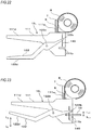
- FIGS. 22 and 23 are configuration views depicting a modified embodiment of the binding device in accordance with the fourth embodiment.
- a cassette storage unit 111a 1 is provided at a part in front of the first gripping part 122d of the handle unit 122 or the second gripping part 111d of the base unit 111.
- the cassette storage unit 111a 1 is provided at a part of a side that faces the cutting blade 44.
- the cassette storage unit 111a 1 is provided at a part of a side that faces the first gripping part 122d of the handle unit 122 via the sheet bundle 10, which is to be placed on the entrance groove 111b, being interposed therebetween.
- the cassette 8 is attached to the front and lower part of the device, and in the binding device 1D 1 , the cassette 8 is attached to a front and upper part of the device, so that there is no shape protruding rearwards from the handle unit 122-side.
- the degree of freedom of shapes of the handle unit 122 and the base unit 111 increases. Therefore, for example, it is possible to make a shape by which it is possible to grip the device with one hand.
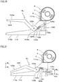
- FIGS. 24 and 25 are configuration views depicting an example of a binding device in accordance with a fifth embodiment.
- a binding device 1E has a base unit 112, a handle unit 123 provided to be rotatable relative to the base unit 112 and a link 124 configured to transmit an operation of the handle unit 123 to the cutting blade 140.
- the base unit 112 has a cassette storage unit 112a, to which the cassette 8 having the roll body 7 of the tape 5 accommodated therein is to be detachably mounted, at a front and lower part. Also, the base unit 112 has an entrance groove 112b in which the sheet bundle 10 is to be inserted. Also, although not shown, the base unit 112 has the conveyor unit configured to convey the tape 5 and the release paper 4 pulled out from the cassette 8, the configuration for preliminarily shaping the piece, and the like, which have been described in the respective embodiments.
- the handle unit 123 is an example of the operation member and is attached to the base unit 112 so as to be rotatable about a shaft 123a serving as a support point.
- the handle unit 123 has a coupling part 123b, to which the link 124 is to be coupled, at one end portion-side, and the other end portion-side becomes a free end.
- the handle unit 123 is provided with a first gripping part 123e for gripping and operating the binding device 1E.
- the base unit 112 is provided with a second gripping part 112e for gripping and operating the binding device 1E, and when operating the binding device 1E, it is possible to operate the same with gripping the first gripping part 123e and the second gripping part 112e.
- the cassette storage unit 112a is provided at a part in front of the first gripping part 123e of the handle unit 123 or the second gripping part 112e of the base unit 112. Also, the cassette storage unit 112a is provided at a part of a side that faces the cutting blade 44 via the sheet bundle 10, which is to be placed on the entrance groove 112b, being interposed therebetween. Also, the cassette storage unit 112a is provided at a part of a side that faces the first gripping part 123e of the handle unit 123 via the sheet bundle 10, which is to be placed on the entrance groove 112b, being interposed therebetween.
- the link 124 is attached to the base unit 112 so as to be rotatable about a shaft 124a serving as a support point.
- the link 124 has a coupling shaft 124b, which is to be coupled with the coupling part 123b of the handle unit 123, at one end portion and a coupling part 124c, to which the cutting blade 140 is to be coupled, at the other end portion.
- the handle unit 123 rotates the shaft 123a serving as a support point
- the link 124 rotates about the shaft 124a serving as a support point
- the rotation operations of the handle unit 123 and the link 124 are transmitted to the cutting blade 140.
- the handle unit 123 When the handle unit 123 is operated in an arrow M 1 direction, the handle unit 123 rotates about the shaft 123a serving as a support point and the link 124 rotates about the shaft 124a serving as a support point, so that the cutting blade 140 is moved in an arrow M 11 direction and penetrates the sheet bundle 10 inserted in the entrance groove 112b. Also, although not shown, the preliminarily shaped piece is held by the cutting blade 140.
- the handle unit 123 When the handle unit 123 is operated in an arrow M 2 direction, the handle unit 123 rotates about the shaft 123a serving as a support point and the link 124 rotates about the shaft 124a serving as a support point, so that the cutting blade 140 is moved in an arrow M 21 direction and the cutting blade 140 having penetrated the sheet bundle 10 is pulled out. By this operation, the piece is pulled out to the surface-side of the sheet bundle 10, in succession to the cutting blade 140.
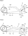
- FIGS. 26 and 27 are configuration views depicting a modified embodiment of the binding device in accordance with the fifth embodiment.
- a cassette storage unit 111a 1 is provided at a part in front of the first gripping part 123e of the handle unit 123 or the second gripping part 112e of the base unit 112. Also, the cassette storage unit 111a 1 is provided at a part of a side that faces the cutting blade 44. Also, the cassette storage unit 111a 1 is provided at a part of a side that faces the first gripping part 123e of the handle unit 123 via the sheet bundle 10, which is to be placed on the entrance groove 111b, being interposed therebetween.
- the cassette 8 is attached to the front and lower part of the device, and in the binding device 1E 1 , the cassette 8 is attached to a front and upper part of the device, so that there is no shape protruding rearwards from the handle unit 123-side.
- a degree of freedom of shapes of the handle unit 123 and the base unit 112 increases. Therefore, for example, it is possible to make a shape by which it is possible to grip the device with one hand.
- the operation of the handle unit 123 is transmitted to the cutting blade 140 by the link 124. Thereby, a degree of freedom of a setting of an operation ratio of the cutting blade 140 to the operation of the handle unit 123 is improved, and the degree of freedom of the shape of the handle unit 123 is further improved.
- FIG. 28 is a configuration view depicting an example of a binding device in accordance with a sixth embodiment.
- a binding device 1F of the sixth embodiment is configured to accommodate the cassette 8 at the rear thereof.
- the equivalent configurations to the binding device 1A of the first embodiment are denoted with the same reference numerals, and the detailed descriptions thereof are omitted.
- the handle unit 12 is provided with the first gripping part 12a 1 for gripping and operating the binding device 1F.
- a base unit 11K is provided with a second gripping part 11K 1 for gripping and operating the binding device 1F, and when operating the binding device 1F, it is possible to operate the same with gripping the first gripping part 12a 1 and the second gripping part 11K 1 .
- the binding device 1F has a cassette storage unit 60F, to which the cassette 8 is to be detachably mounted, at the rear of a device main body 110F having the base unit 11 K and the handle unit 12.
- the cassette storage unit 60F is an example of the storage unit and is provided at a part of the device main body 110F, which is at the rear of the first gripping part 12a 1 of the handle unit 12 or the second gripping part 11k 1 of the base unit 11K, in the sixth embodiment, at the rear of the base unit 11K.
- the cassette 8 is attached to the rear of the device main body 110F, so that it is possible to suppress the size in the height direction. Thereby, the degree of freedom of the shape of the base unit 11K increases, so that it is possible to make a shape suitable for the gripping.
- FIGS. 29 and 30 are configuration views depicting an example of a binding device in accordance with a seventh embodiment.
- the equivalent configurations to the binding device 1D of the fourth embodiment are denoted with the same reference numerals, and the detailed descriptions thereof are omitted.
- the handle unit 122 is provided with the first gripping part 122d for gripping and operating the binding device 1G.
- the base unit 111 is provided with the second gripping part 111d for gripping and operating the binding device 1G, and when operating the binding device 1G, it is possible to operate the same with gripping the first gripping part 122d and the second gripping part 111d.
- a cassette storage unit 111g is provided at a part of the base unit 111, which is at the rear of the second gripping part 111d.
- the cassette 8 is attached to a position at the rear of the device, at which the gripping is not disturbed.
- the degree of freedom of the shapes of the handle unit 122 and the base unit 111 increases. Therefore, for example, it is possible to make a shape by which it is possible to grip the device with one hand.
- FIGS. 31 and 32 are configuration views depicting an example of a binding device in accordance with an eighth embodiment.
- the equivalent configurations to the binding device 1E of the fifth embodiment are denoted with the same reference numerals, and the detailed descriptions thereof are omitted.
- the handle unit 123 is provided with the first gripping part 123e for gripping and operating the binding device 1H.
- the base unit 112 is provided with the second gripping part 112e for gripping and operating the binding device 1H, and when operating the binding device 1H, it is possible to operate the same with gripping the first gripping part 123e and the second gripping part 112e.
- a cassette storage unit 112h is provided at a part of the base unit 111, which is at the rear of the second gripping part 112e.
- the cassette 8 is attached to a position at the rear of the device, at which the gripping is not disturbed.
- the degree of freedom of the shapes of the handle unit 123 and the base unit 112 increases. Therefore, for example, it is possible to make a shape by which it is possible to grip the device with one hand.
- FIG. 33 illustrates a modified embodiment of the cassette.
- a modified embodiment of the accommodation shape of the tape 5, which is the disposable, is described.
- a cassette 80 has a configuration where the long tape 5 is to be accommodated with being folded in a bellows shape and is to be pulled out from the drawing port 80a.
- the accommodation shape of the tape 5 is not particularly limited inasmuch as it folded so that it is accommodated with a predetermined size, such as a shape wound in a roll shape, a shape folded in a bellows shape, and the like.
- the present invention is applied to a device configured to bind a sheet bundle with a piece made of paper or the like.
Landscapes
- Engineering & Computer Science (AREA)
- Mechanical Engineering (AREA)
- Life Sciences & Earth Sciences (AREA)
- Forests & Forestry (AREA)
- Textile Engineering (AREA)
- Folding Of Thin Sheet-Like Materials, Special Discharging Devices, And Others (AREA)
- Perforating, Stamping-Out Or Severing By Means Other Than Cutting (AREA)
- Basic Packing Technique (AREA)
Abstract
Description
- The present invention relates to a binding device configured to bind a sheet bundle with a piece made of an easily bendable non-metal material having a thin foil shape such as paper, resin or the like.
- A device configured to bind a sheet bundle such as documents with a member referred to as a piece made of paper or the like, not a metal needle, has been known.
- As the device, a technology has been suggested in which a cassette configured to accommodate therein a long disposable having the piece bonded to the disposable is attached at the rear of a device main body (refer to
Patent Documents - Also in a device where a configuration for penetrating the sheet bundle and a configuration for binding the sheet bundle with the piece are separately provided, the cassette having the disposable accommodated therein is attached at the rear of the device main body (refer to Patent Document 4).
-
- Patent Document 1: Japanese Patent Application Publication No.
H10-871A - Patent Document 2: Japanese Patent No.
3,122,807B - Patent Document 3: Japanese Patent Application Publication No.
2003-25753A - Patent Document 4: Japanese Patent Application Publication No.
H10-24669A - For example, as disclosed in
Patent Document 1,Patent Document 2 andPatent Document 3, according to the configuration where the storage unit configured to store therein the disposable is provided at the rear of the device main body, the storage unit, the cassette to be mounted to the storage unit, and the like protrude from the rear of the device main body. In the configuration where the sheet bundle is bound with the piece, since the disposable of which a plurality of sides is bonded to a long release paper is supplied with being wound into a roll shape, a space for accommodating therein the disposable becomes large. For this reason, in the configuration where the storage unit configured to accommodate therein the disposable, the cassette to be mounted to the storage unit, and the like protrude from the rear of the device main body, a size of the device main body in a front and rear direction increases, so that a wide operation space is required. - Also, in
Patent Document 1,Patent Document 2 andPatent Document 3, it is difficult to perform the binding operation with gripping the device main body. Particular, inPatent Document 1,Patent Document 2 andPatent Document 3, the device is configured to perform the binding by straightly pushing down a pressing handle, a pushing-down member or a pushing-down part in an upper and lower direction, without the assumption that the binding operation is performed with gripping the device main body. - Also, regarding the device configured to perform the binding by straightly pushing down the pressing handle, the pushing-down member or the pushing-down part in the upper and lower direction, as disclosed in
Patent Document 1,Patent Document 2 andPatent Document 3, a device having an operation handle configured to rotate about a shaft serving as a support point has been also suggested, as disclosed inPatent Document 4. However, the device is a large-scale device capable of performing the binding at two places at the same time, so that it is difficult to perform the binding operation with gripping the device main body. - The present invention has been made in view of the above situations, and an object thereof is to provide a small-scale binding device capable of performing a binding operation with gripping a device main body.
- In order to solve the above problems, the present invention is a binding device comprising a device main body comprising a base unit, on which a sheet bundle is to be placed, and an operation member, a cutting blade configured to penetrate the sheet bundle by an operation of the operation member and to insert a piece into the sheet bundle, a storage unit configured to store therein a disposable of which a plurality of pieces is bonded to a long release paper, and a conveying unit configured to convey the disposable pulled out from the storage unit, wherein the storage unit is provided at a part of the device main body in front of or at a rear of a gripping part of the operation member.
- The present invention is a binding device comprising, a device main body comprising a base unit, on which a sheet bundle is to be placed, and an operation member, a cutting blade configured to penetrate the sheet bundle by an operation of the operation member and to insert a piece into the sheet bundle, a storage unit configured to store therein a disposable of which a plurality of pieces is bonded to a long release paper, and a conveying unit configured to convey the disposable pulled out from the storage unit, wherein the storage unit is provided at a part of the device main body, which faces a gripping part of the operation member via the sheet bundle, which is to be placed on the base unit, being interposed therebetween.
- The present invention is a binding device comprising a device main body comprising a base unit, on which a sheet bundle is to be placed, and an operation member, a cutting blade configured to penetrate the sheet bundle by an operation of the operation member and to insert a piece into the sheet bundle, a storage unit configured to store therein a disposable of which a plurality of pieces is bonded to a long release paper, and a conveying unit configured to convey the disposable pulled out from the storage unit, wherein the storage unit is provided at a part of the device main body, which is in front of or at a rear of a first gripping part of the operation member or a second gripping part of the base part.
- According to the present invention, the storage unit of the disposable is provided at the part of the device main body, in front of or at the rear of the gripping part of the operation member. Therefore, it is possible to grip the device main body without any difficulty in gripping the gripping part of the operation member and to perform the operation with gripping the device main body.
- Also, according to the present invention, since the storage unit of the disposable is provided at the part of the device main body, which faces the gripping part of the operation member via the sheet bundle, which is to be placed on the base unit, being interposed therebetween, it is possible to make the device main body smaller. Also, it is possible to grip the device main body without any difficulty in gripping the gripping part of the operation member and to perform the operation with gripping the device main body.
- Also, according to the present invention, the storage unit of the disposable is provided at the part of the device main body, in front of or at the rear of the first gripping part of the operation member or the second gripping part of the base unit. Therefore, it is possible to grip the device main body without any difficulty in gripping the first gripping part of the operation member or the second gripping part of the base unit and to perform the operation with gripping the device main body.
-
-
FIG. 1 is a configuration view depicting an example of a binding device in accordance with a first embodiment. -
FIG. 2 is a configuration view depicting an example of the binding device in accordance with the first embodiment. -
FIG. 3 is a configuration view depicting an example of a piece having bound a sheet bundle. -
FIG. 4 is a configuration view depicting an example of the piece. -
FIG. 5 is a perspective view depicting a driving mechanism of a cutting blade. -
FIG. 6 illustrates an open and closed state of a cassette storage unit. -
FIGS. 7A to 7E illustrate an outline of an operation of binding a sheet bundle with the piece. -
FIG. 8 illustrates an example of an operation of the binding device in accordance with the first embodiment. -
FIG. 9 illustrates an example of the operation of the binding device in accordance with the first embodiment. -
FIG. 10 illustrates an example of the operation of the binding device in accordance with the first embodiment. -
FIG. 11 illustrates an example of the operation of the binding device in accordance with the first embodiment. -
FIG. 12 illustrates an example of the operation of the binding device in accordance with the first embodiment. -
FIG. 13 illustrates an example of the operation of the binding device in accordance with the first embodiment. -
FIG. 14 is a configuration view depicting an example of a binding device in accordance with a second embodiment. -
FIG. 15 illustrates an open and closed state of a cassette storage unit. -
FIG. 16 is a configuration view depicting a modified embodiment of the binding device in accordance with the second embodiment. -
FIG. 17 is a configuration view depicting another modified embodiment of the binding device in accordance with the second embodiment. -
FIG. 18 is a configuration view depicting an example of a binding device in accordance with a third embodiment. -
FIG. 19 is a configuration view depicting an example of the binding device in accordance with the third embodiment. -
FIG. 20 is a configuration view depicting an example of a binding device in accordance with a fourth embodiment. -
FIG. 21 is a configuration view depicting an example of the binding device in accordance with the fourth embodiment. -
FIG. 22 is a configuration view depicting a modified embodiment of the binding device in accordance with the fourth embodiment. -
FIG. 23 is a configuration view depicting the modified embodiment of the binding device in accordance with the fourth embodiment. -
FIG. 24 is a configuration view depicting an example of a binding device in accordance with a fifth embodiment. -
FIG. 25 is a configuration view depicting an example of the binding device in accordance with the fifth embodiment. -
FIG. 26 is a configuration view depicting a modified embodiment of the binding device in accordance with the fifth embodiment. -
FIG. 27 is a configuration view depicting the modified embodiment of the binding device in accordance with the fifth embodiment. -
FIG. 28 is a configuration view depicting an example of a binding device in accordance with a sixth embodiment. -
FIG. 29 is a configuration view depicting an example of a binding device in accordance with a seventh embodiment. -
FIG. 30 is a configuration view depicting an example of the binding device in accordance with the seventh embodiment. -
FIG. 31 is a configuration view depicting an example of a binding device in accordance with an eighth embodiment. -
FIG. 32 is a configuration view depicting an example of the binding device in accordance with the eighth embodiment. -
FIG. 33 illustrates a modified embodiment of the cassette. - Hereinafter, embodiments of the binding device of the present invention will be described with reference to the drawings.
-
FIGS. 1 and2 are configuration views depicting an example of a binding device in accordance with a first embodiment. Here,FIG. 1 depicts an internal configuration of abinding device 1A, andFIG. 2 depicts an external configuration of thebinding device 1A. Also,FIG. 3 is a configuration view depicting an example of a piece having bound a sheet bundle, andFIG. 4 is a configuration view depicting an example of the piece. - First, a piece and a sheet bundle, which are processing targets of the
binding device 1A, are described. As shown inFIG. 3 , thebinding device 1A of the first embodiment is a device configured to bind asheet bundle 10 by winding apiece 2, which is a disposable, to thesheet bundle 10 having a plurality of stacked sheets. Thesheet bundle 10 is formed by stacking sheets such as documents, sheet-like members formed of a metal or resin material, and the like. - One side of the
piece 2 is wound from a lower surface, which is-one surface of thesheet bundle 10, to anend portion 10a-side of thesheet bundle 10. Also, the other side of thepiece 2 is wound through a through-hole 10b formed in thesheet bundle 10. The respective end portions of thepiece 2 are bonded to an upper surface, which is the other surface of thesheet bundle 10, so that the piece binds thesheet bundle 10. - As shown in
FIG. 4 , thepiece 2 has a rectangular shape, for example. Onesurface 2a of thepiece 2 is a planar surface, and theother surface 2b is provided with anadhesive layer 3. A plurality of thepieces 2 is temporarily bonded to along release paper 4 in a longitudinal direction, for example. Thereby, even when the piece is used after it has been left for a long time, it is possible to prevent an adhesive force of theadhesive layer 3 from being lowered. Also, thepiece 2 is made of an easily bendable non-metal material having a thin foil shape. - Also, a
tape 5 consisting of thepiece 2 and therelease paper 4 is wound into a roll shape and is accommodated in thebinding device 1A, as a roll body, for example. Thepiece 2 and therelease paper 4 are formed with a plurality of engagingholes 6, in which a mechanism configured to convey thetape 5 is to be engaged, with a predetermined interval in the longitudinal direction. - Subsequently, a configuration of the
binding device 1A is described. Thebinding device 1A is configured to preliminarily shape thepiece 2 by relative movement between thesheet bundle 10 and thepiece 2 resulting from movement of thesheet bundle 10. As shown inFIGS. 1 and2 , the binding device includes abase unit 11A and ahandle unit 12 configured to be rotatable relative to thebase unit 11A. Also, thebinding device 1A includes a holdingunit 20 configured to hold and move thesheet bundle 10, which is a binding target, a bindingunit 40 configured to shape thepiece 2 in corporation with the holdingunit 20 and to bind thesheet bundle 10 with thepiece 2, aconveyor unit 50 as an example of the piece conveyor unit configured to convey thetape 5 in corporation with the holdingunit 20, and acassette storage unit 60A to which acassette 8 having aroll body 7 of thetape 5 accommodated therein is to be detachably mounted. - The
handle unit 12 is an example of the operation member. Ashaft 12m provided at one end portion-side of thehandle unit 12 is engaged with ashaft support part 11m provided at one end portion-side of thebase unit 11A. Thereby, thehandle unit 12 is attached to thebase unit 11A so that one end portion-side thereof can rotate about theshaft 12m, which is a support point, and the other end portion-side becomes a free end. Thehandle unit 12 is provided with agripping part 12a for gripping and operating thebinding device 1A. When operating thebinding device 1A, it is possible to operate the same with gripping thegripping part 12a. - The
binding device 1A is configured so that when the free end-side of thehandle unit 12 is operated, thehandle unit 12 is rotated about theshaft 12m serving as a support point and the rotating operation of thehandle unit 12 is transmitted to the bindingunit 40 to operate the bindingunit 40, as described later. - Herein, a using aspect that the
binding device 1A is used with being placed on a desk or the like is assumed. In below descriptions, a side at which thebase unit 11A is provided is defined as a lower side in an upper and lower direction, such as a lower surface, a lower side, a downward side and the like, and a side at which thehandle unit 12 is defined as an upper side in the upper and lower direction, such as an upper surface, an upper side, an upward side and the like. Also, the free end-side of thehandle unit 12 is defined as a front side in a front and rear direction, such as a front surface, a front side, a forward side and the like, and a side at which theshaft 12m is defined as a rear side in the front and rear direction, such as a rear surface, a rear side, a rearwards side and the like. - The
base unit 11A has amain frame body 11e and alower frame body 11f. Thebase unit 11A is provided with theshaft support part 11m at a rear and upper part of themain frame body 11e. Also, thebase unit 11A is attached with thelower frame body 11f to be rotatable about ashaft 11g provided at a rear and lower part of themain frame body 11e and serving as a support point. Thebase unit 11A is configured so that when thelower frame body 11f is rotated in an arrow J1 direction and an arrow J2 direction, thelower frame body 11f is opened rearwards and a lower part of thebase unit 11A is opened and closed. In addition, thebase unit 11A has amovement support part 11n configured to moveably support the holdingunit 20 and provided at themain frame body 11e. - The
movement support part 11n is provided at a front and upper surface-side of thebase unit 11A with facing the free end-side of thehandle unit 12 and is configured as a groove part provided along the front and rear direction and configured to guide movement of the holdingunit 20 in an arrow F direction and an arrow R direction. - Subsequently, the holding
unit 20 is described. The holdingunit 20 is an example of the placement unit, is attached to a front and upper surface of thebase unit 11A so as to be moveable in the front and rear direction by themovement support part 11n, and is configured to be moveable between an inserting/drawing position of thesheet bundle 10 located below the free end-side of thehandle unit 12 and a binding position located below the bindingunit 40. - The holding
unit 20 includes atray 23 on which thesheet bundle 10, which is a binding target, is to be placed, and a pushingmember 24 rotatably attached to thetray 23 and configured to push thesheet bundle 10 to thetray 23 by a rotation operation. - In the meantime, as described later, since the holding
unit 20 relates to a partial preliminary shaping of an operation of once winding thepiece 2 to thesheet bundle 10, the holding unit configures the preliminary shaping unit. Also, since the holdingunit 20 relates to a part of an operation of conveying thetape 5, the holding unit configures the conveying unit. - In the first embodiment, the
tray 23 is configured to have a rectangular flat plate shape in conformity to the shape of thebase unit 11A, and has aplacement part 23a on which thesheet bundle 10 is to be placed, and an engagingguide part 23b to be engaged with themovement support part 11n of thebase unit 11A. The engagingguide part 23b has a shape protruding downwards from a lower surface of theplacement part 23a, and is configured to engage with themovement support part 11n of thebase unit 11A. Thereby, the holdingunit 20 can move between the inserting/drawing position and the binding position as the engagingguide part 23b is guided to themovement support part 11n. - Also, the holding
unit 20 is provided with arotary shaft 23c configured to rotatably support the pushingmember 24 at a rear end portion of theplacement part 23a. In addition, a rear end-side of theplacement part 23a is provided with acutout part 23d having a rectangular shape at a substantial center in a width direction. Thecutout part 23d is configured by providing theplacement part 23a with an opening, in which thepiece 2 configured to bind thesheet bundle 10 and a cutting blade 44 (which will be described later) of the bindingunit 40 can be introduced when the holdingunit 20 is moved to the binding position, while avoiding the adhesion position of thepiece 2. - The holding
unit 20 has a holdingclaw 23e configured to hold therelease paper 4. The holdingclaw 23e is an example of the conveying unit, is provided at the engagingguide part 23b with facing a conveyance path of therelease paper 4, and moves in the arrow F direction and the R direction when the holdingunit 20 moves. The holdingclaw 23e is configured to be rotatable by a rotation operation about ashaft 23f serving as a support point, which is provided at an upstream side with respect to the conveying direction in which therelease paper 4 is to be drawn out, and is urged in the direction of therelease paper 4 by aspring 23g. - When the holding
claw 23e is moved in the arrow R direction by an operation of moving the holdingunit 20 from the inserting/drawing position to the binding position, the holding claw rotates about theshaft 23f serving as a support point in an arrow G1 direction, against thespring 23g, and retreats from the conveyance path of therelease paper 4. Thereby, the holding claw is not engaged with the engaginghole 6 of therelease paper 4, so that thetape 5 and therelease paper 4 are not reversely conveyed by the operation of moving the holdingunit 20 from the inserting/drawing position to the binding position. - In the meantime, when the holding
claw 23e is moved in the arrow F direction by an operation of moving the holdingunit 20 from the binding position to the inserting/drawing position, the holding claw rotates about theshaft 23f serving as a support point in an arrow G2 direction by a force of thespring 23g and protrudes into the conveyance path of therelease paper 4. Thereby, the holdingclaw 23e is engaged with the engaginghole 6 of therelease paper 4, so that thetape 5 and therelease paper 4 are drawn out by the operation of moving the holdingunit 20 from the binding position to the inserting/drawing position. - The pushing
member 24 is rotatably supported at a rear end-side by therotary shaft 23c, and is configured to rotate in an arrow H1 direction and an arrow H2 direction with respect to thetray 23, thereby opening and closing a front side of thetray 23. The pushingmember 24 is made of an elastic material, andelastic pieces 24b of which a front side is configured as a base end are integrally provided. - The
elastic pieces 24b are provided by two members protruding from the pushingmember 24 so that they are positioned at right and left sides of thecutout part 23d of theplacement part 23a. A rear end-side of the elastic piece is a free end and is bent towards thetray 23. Theelastic pieces 24b are contacted at rear ends thereof to thetray 23 and are configured to raise and keep the entire pushingmember 24. - In the meantime, regarding the
tray 23 and the pushingmember 24 configuring the holdingunit 20, the pushingmember 24 is provided so that a binding position of thesheet bundle 10 is not to deviate from thetray 23. When the binding position of thesheet bundle 1 is set not to deviate from thetray 23 upon a binding operation, the pushingmember 24 is not necessarily provided. -
FIG. 5 is a perspective view depicting a driving mechanism of the cutting blade. In the below, a mechanism configured to operate the bindingunit 40 and thecutting blade 44 by thehandle unit 12 is described with reference to the respective drawings. - The binding
unit 40 has a drivingmember 41 provided on an inner and lower surface of thehandle unit 12. Also, the bindingunit 40 has aguide lever 42 configured to move in an upper and lower direction by displacement of the drivingmember 41, apressing lever 43 configured to press thepiece 2 configured to bind thesheet bundle 10, and acutting blade 44 configured to penetrate thesheet bundle 10, which are provided in acomponent arranging part 27. - The
component arranging part 27 is integrally provided with thebase unit 11A, and anentrance groove 28 in which the holdingunit 20 moving to the binding position is to be introduced is provided on a moving path of the holdingunit 20. Also, thecomponent arranging part 27 and thebase unit 11A have a piecestandby part 28a at which thepiece 2 released from therelease paper 4 is to stand by and which is provided on a moving path of thesheet bundle 10 held by the holdingunit 20 to be inserted into theentrance groove 28. Theentrance groove 28 is an opening provided with being spaced between thebase unit 11A and thecomponent arranging part 27. When the holdingunit 20 is introduced into the entrance groove, the pushingmember 24 is pressed in an arrow H1 direction of coming close to thetray 23, so that thesheet bundle 10 is interposed and held between thetray 23 and the pushingmember 24. The holdingunit 20, theentrance groove 28 and thepressing lever 43 configure the preliminary shaping unit configured to preliminarily shape thepiece 2 by the relative rotation between thesheet bundle 10 and thepiece 2 resulting from the movement of the holdingunit 20. - The binding
unit 40 has thepressing lever 43 and thecutting blade 44, which are provided above theentrance groove 28, and the drivingmember 41 configured to transmit the movement of thehandle unit 12 to thepressing lever 43 via thecutting blade 44 and theguide lever 42 and havingfirst guide holes 41a and second guide holes 41b. Thefirst guide hole 41a is configured as a long hole and aconvex portion 42a of theguide lever 42 is engaged thereto. Thesecond guide hole 41b is configured as a long hole and aconvex portion 49a of an attaching member 49 (FIG. 5 ) having the cuttingblade 44 attached thereto is engaged to the second guide hole. - When the free end-side of the
handle unit 12 is operated and thehandle unit 12 is thus rotated about theshaft 12m serving as a support point, positions of thefirst guide hole 41a and thesecond guide hole 41b of the drivingmember 41 are displaced in the upper and lower direction. Thereby, the rotation of thehandle unit 12 linearly moves theguide lever 42 in the upper and lower direction. Also, thecutting blade 44 is linearly moved in the upper and lower direction. - The
guide lever 42 is configured so that it is to be guided and moved in the upper and lower direction by thecomponent arranging part 27. In theguide lever 42, an elastic member such as acoil spring 45 is wound and inserted. Thecoil spring 45 configures a so-called return spring of thehandle unit 12, and a lower end portion thereof is received at thebase unit 11A by a receivingpart 46 of thecomponent arranging part 27. Also, an upper end portion of thecoil spring 45 is received at thehandle unit 12 by theconvex portion 42a of theguide lever 42 engaged to thefirst guide hole 41 a of the drivingmember 41. - Thereby, the
handle unit 12 is urged in an arrow U direction of separating from thebase unit 11A by thecoil spring 45. Also, when thehandle unit 12 is pushed in an arrow D direction, thecoil spring 45 is contracted and theguide lever 42 is linearly moved in the arrow D direction. Herein, thefirst guide hole 41a is configured as a long hole, so that theconvex portion 42a can move along thefirst guide hole 41a of which a locus of displacement is a circular arc shape about theshaft 12m and theguide lever 42 is linearly moved without a locus of displacement of theconvex portion 42a forming into a circular arc shape. - The
pressing lever 43 is provided in front of theguide lever 42. Thepressing lever 43 has apressing part 43a configured to press and bond thepiece 2 to thesheet bundle 10. Thepressing lever 43 is wound with apressing spring 47 consisting of an elastic member such as a coil spring. Thepressing spring 47 has one end engaged to thepressing part 43a and the other end engaged to the movingmember 48 configured to move in conjunction with theguide lever 42. - The
cutting blade 44 is provided in front of thepressing lever 43. As shown inFIG. 5 , thecutting blade 44 is formed with aninsertion hole 44b, which is provided above ablade part 44a and thepiece 2 is to be inserted therein. Thecutting blade 44 is attached to the attachingmember 49, and the attachingmember 49 is connected to theguide lever 42. - At a state where the
handle unit 12 is at a standby position, theblade part 44a of thecutting blade 44, which is provided at a tip end, does not protrude downwards from theentrance groove 28. A height and a moving amount of theblade part 44a are set so that when thehandle unit 12 is pressed in the arrow U direction, the blade part penetrates thesheet bundle 10 pressed by thepressing part 43a of thepressing lever 43. - As shown in
FIG. 5 , theconvex portions 49a protrude laterally from right and left sides of the attachingmember 49 having the cuttingblade 44. Eachconvex portion 49a is engaged to thesecond guide hole 41 b of the drivingmember 41. Herein, thesecond guide hole 41b is configured as a long hole, so that theconvex portion 49a can move along thesecond guide hole 41b of which a locus of displacement is a circular arc shape about theshaft 12m and thecutting blade 44 is linearly moved without a locus of displacement of theconvex portion 49a forming a circular arc shape. - According to the binding
unit 40 configured as described above, when thehandle unit 12 is pressed down in the arrow D direction, thehandle unit 12 is rotated above theshaft 12m serving as a support point in the arrow D direction, so that theconvex portions 49a configured to drive the cuttingblade 44 by the second guide holes 41b of the drivingmember 41 are pressed and thecutting blade 44 is thus moved in the arrow D direction. Thereby, thecutting blade 44 penetrates thesheet bundle 10. - Also, when the
handle unit 12 is pushed up in the arrow U direction, thehandle unit 12 is rotated above theshaft 12m serving as a support point in the arrow U direction, so that theconvex portions 49a configured to drive the cuttingblade 44 by the second guide holes 41b of the drivingmember 41 are pushed up and thecutting blade 44 is thus moved in the arrow U direction. Thereby, thecutting blade 44 having penetrated thesheet bundle 10 is pulled out. During the pulling-out operation of thecutting blade 44, thepiece 2 held by thecutting blade 44 is pulled out to the surface-side of thesheet bundle 10, in succession to thecutting blade 44, as described later. - Subsequently, a
pressing roller 56 configuring a part of the bindingunit 40 is described. Thepressing roller 56 is provided in front of thecutting blade 44. Thepressing roller 56 is urged downwards by an elastic member such as acoil spring 57, and presses thepiece 2 having bound thesheet bundle 10 when the holdingunit 20 is moved between the binding position and the inserting/drawing position. - Subsequently, the
conveyor unit 50 and thecassette storage unit 60A are described. Theconveyor unit 50 is an example of the conveying unit, and has a firstguide configuring member 50a provided at themain frame body 11e of thebase unit 11A and a secondguide configuring member 50b provided at thelower frame body 11f with facing the firstguide configuring member 50a, which members configure aconveyance path 51 of thetape 5 before thepiece 2 to be carried by the operation of the holdingunit 20 is to be released and therelease paper 4 from which thepiece 2 has been released. - The
conveyor unit 50 has afirst roller 52a configured to guide thetape 5 pulled out from thecassette 8 accommodated in thecassette storage unit 60A and asecond roller 52b configured to face more downwards than a horizontal direction on the conveyance path of thetape 5 at a downstream side of thefirst roller 52a, and configures a bent conveyance path. Also, theconveyor unit 50 has an engagingclaw 52c configured to hold therelease paper 4 and a retreat part 52d configured to retreat therelease paper 4 held with the engagingclaw 52c. - The
first roller 52a of theconveyor unit 50 is provided at the firstguide configuring member 50a. Also, thesecond roller 52b and the engagingclaw 52c of theconveyor unit 50 are provided at the secondguide configuring member 50b. In addition, the retreat part 52d of theconveyor unit 50 is configured in a space between the firstguide configuring member 50a and the secondguide configuring member 50b. - The
conveyor unit 50 is configured to bend the conveyance path to an acute angle by thesecond roller 52b, thereby configuring arelease part 52e configured to release thepiece 2 from thetape 5 by using rigidness of thepiece 2. In theconveyor unit 50, thetape 5 pulled out from thecassette 8 accommodated in thecassette storage unit 60A is conveyed upwards with being guided to thefirst roller 52a. Then, thetape 5 is guided to thesecond roller 52b and is bent to an acute angle. Therelease paper 4 is bent to an acute angle at therelease part 52e, so that only thepiece 2 temporarily attached to therelease paper 4 travels straight upwards and thepiece 2 is straightly released by about a half from therelease paper 4 without being bent. Thepiece 2 released from therelease paper 4 waits for thesheet bundle 10 with theadhesive layer 3 shown inFIG. 4 facing towards thesheet bundle 10 that is being introduced with being held by the holdingunit 20. Therelease paper 4 downstream of thesecond roller 52b is conveyed to the front of thebase unit 11A and is discharged. - The engaging
claw 52c is provided downstream of thesecond roller 52b, protrudes to theconveyance path 51 with being inclined forward, and is engaged with the engaginghole 6 of therelease paper 4. The retreat part 52d is configured by providing a space, in which therelease paper 4 is to be introduced, at a position facing the engagingclaw 52c. - When the holding
unit 20 is moved from the inserting/drawing position to the binding position, the holdingclaw 23e is moved in the arrow R direction and thetape 5 and therelease paper 4 are thus applied with a force in a reverse conveying direction, the engagingclaw 52c is engaged with the engaginghole 6 of therelease paper 4, so that thetape 5 and therelease paper 4 are not reversely conveyed. - On the other hand, when the holding
unit 20 is moved from the binding position to the inserting/drawing position, the holdingclaw 23e is moved in the arrow F direction and thetape 5 and therelease paper 4 are thus applied with a force in a forward conveying direction, the engagingclaw 52c is disengaged from the engaginghole 6 of therelease paper 4, therelease paper 4 is introduced into the retreat part 52d and thetape 5 and therelease paper 4 can be conveyed in the forward direction. When the force of conveying therelease paper 4 is not applied, the engaginghole 6 of therelease paper 4 is engaged with the engagingclaw 52c. - The
cassette storage unit 60A is an example of the storage unit, and is provided at a lower part of the devicemain body 110A having thebase unit 11A and thehandle unit 12. Thecassette storage unit 60A is provided at a rear and lower part of thebase unit 11A, in the first embodiment. In thecassette 8 to be accommodated in thecassette storage unit 60A, theroll body 7 of which thetape 5 is wound in an involution form where the surface having thepiece 2 bonded thereto faces towards an inner side is accommodated, and thetape 5 is to be pulled out from a drawingport 8a. - In the
cassette storage unit 60A, thecassette 8 is accommodated in a vertical direction so that a circumferential direction of theroll body 7 becomes a vertical direction, and thetape 5 pulled out from the drawingport 8a of thecassette 8 is guided to theconveyance path 51 from the lower part of theconveyor unit 50. In the first embodiment, an external shape of thecassette 8 is configured so that it does not protrude rearwards beyond the rear end of thehandle unit 12. - The
cassette storage unit 60A is provided at a part of the devicemain body 110A, which is at the rear of thegripping part 12a of thehandle unit 12, i.e., at thebase unit 11A in the first embodiment. Also, thecassette storage unit 60A is provided at a part facing thecutting blade 44 with thesheet bundle 10, which is to be placed as described later by the holdingunit 20, being interposed therebetween. Also, thecassette storage unit 60A is provided at a part of a side at which thedrawing port 8a of thecassette 8 faces thecutting blade 44 via theconveyor unit 50 being interposed therebetween. Also, thecassette storage unit 60A is provided at a part of a side that faces thegripping part 12a of thehandle unit 12 via thesheet bundle 10, which is to be placed by the holdingunit 20, being interposed therebetween. - The
cassette 8 is accommodated in thecassette storage unit 60A so that the drawingport 8a is positioned just below the conveyance path reaching therelease part 52e, i.e., so that the drawingport 8a faces upwards, in the first embodiment, and a part at which thetape 5 is to be pulled out from the drawingport 8a is provided below theconveyance path 51. Thereby, the conveyance path from the drawingport 8a to therelease part 52e is substantially linear. - The
release part 52e is configured to bend the conveyance path to an acute angle with thesecond roller 52b, thereby releasing thepiece 2 from thetape 5 by using the rigidness of thepiece 2. The conveyance path reaching therelease part 52e is made to be linear, so that the load is reduced upon the conveying of thetape 5 and therelease paper 4. - In the
cassette storage unit 60A, the accommodation position of thecassette 8 is set in conformity to the position of theshaft 11g of thelower frame body 11f. Thereby, the cassette storage unit is opened and closed by the rotation operation of thelower frame body 11f about theshaft 11g serving as a support point. -
FIG. 6 illustrates an opened and closed state of the cassette storage unit. In the below, operations of attaching and detaching thecassette 8, thetape 5 and therelease paper 4 in thebinding device 1A are described. - As shown in
FIG. 6 , when thelower frame body 11f is opened by a rotation operation about theshaft 11g serving as a support point in an arrow J1 direction, the front side of thecassette storage unit 60A is opened. Thereby, thecassette 8 can be attached and detached from the front side of thebase unit 11A. - Also, when the
lower frame body 11f is opened, the secondguide configuring member 50b is opened downwards with respect to the firstguide configuring member 50a, and thesecond roller 52b and the engagingclaw 52c are retreated from the conveyance path, so that theconveyance path 51 is exposed. Thereby, it is possible to easily perform the operations of pulling out thetape 5 from thecassette 8 mounted to thecassette storage unit 60A, hooking the engaging hole 6 (FIG. 4 ) to the engagingclaw 52c and mounting thetape 5 and therelease paper 4 to theconveyance path 51. - As shown in
FIG. 1 , when thelower frame body 11f is closed by a rotation operation about theshaft 11g serving as a support point in an arrow J2 direction, thecassette 8 is held in thecassette storage unit 60A. Also, when thelower frame body 11f is closed, the firstguide configuring member 50a and the secondguide configuring member 50b face each other and form theconveyance path 51 and thetape 5 and therelease paper 4 are mounted to a predetermined conveyance path. - In this way, the
cassette storage unit 60A is provided at the lower part of thebase unit 11A and thelower frame body 11f is configured to be openable and closable, so that thecassette storage unit 60A and theconveyance path 51 can be opened and closed. Therefore, at the state where thelower frame body 11f is opened, the entire conveyance path of thetape 5 and therelease paper 4, including parts to be pulled out from thecassette storage unit 60A, is exposed, as shown inFIG. 6 . Thereby, it is possible to easily attach and detach thetape 5 and therelease paper 4. - In the meantime, in the first embodiment, the
roll body 7 is accommodated in thecassette 8. However, a configuration where thecassette storage unit 60A is formed in conformity to theroll body 7 and theroll body 7 can be directly accommodated in thecassette storage unit 60A is also possible. -
FIG. 7 illustrates an outline of an operation of binding the sheet bundle with the piece, andFIGS. 8 to 13 illustrate an example of an operation of the binding device of the first embodiment. In the below, an operation of binding thesheet bundle 10 with thepiece 2 in thebinding device 1A of the first embodiment is described. - At a standby state shown in
FIGS. 7A and8 , thehandle unit 12 is not operated and thecutting blade 44 is retreated to a standby position above theentrance groove 28. Also, the pushingmember 24 is rotated in the arrow H2 direction, so that the holdingunit 20 is opened relative to thetray 23 and is located at the inserting/drawing position Pp1. - Also, about a half part of the
piece 2 released from therelease paper 4 protrudes to the piecestandby part 28a, is held by the holdingunit 20 and stands by on a moving path of thesheet bundle 10 moving from the inserting/drawing position Pp1 to the binding position Pp2, as shown inFIG. 7A . - In the
binding device 1A at the standby state, when thesheet bundle 10 is put on theplacement part 23a of thetray 23, the pushingmember 24 and theelastic piece 24b are elastically deformed in accordance with a thickness of thesheet bundle 10 and is temporarily pressed to theplacement part 23a by theelastic pieces 24b. - At a holding state of the
sheet bundle 10 shown inFIG. 9 , when the pushingmember 24 is pushed in the arrow H1 direction by an operator, the pushingmember 24 is rotated about therotary shaft 23c serving as a support point in the arrow H1 direction and the pushingmember 24 and theelastic pieces 24b are further elastically deformed, so that thesheet bundle 10 is held between the pushingmember 24 and thetray 23 by theelastic pieces 24b. - At a state of
FIG. 10 where thepiece 2 is to be preliminarily shaped, when the holdingunit 20 holding thesheet bundle 10 is pushed in the arrow R direction by the operator, the holdingunit 20 holding thesheet bundle 10 is moved from the inserting/drawing position Pp1 in the arrow R direction, so that theend portion 10a of thesheet bundle 10 is contacted to thepiece 2 standing by at the piecestandby part 28a. When the holdingunit 20 holding thesheet bundle 10 is further pushed in the arrow R direction, thesheet bundle 10 and thepiece 2 pushed to thesheet bundle 10 are interposed between thepressing part 43a of thepressing lever 43 and theentrance groove 28. - Then, when the holding
unit 20 holding thesheet bundle 10 is moved to the binding position Pp2, thepiece 2 is introduced into an unevenness shape formed by a combination of thepressing part 43a of thepressing lever 43, theentrance groove 28 and theend portion 10a of thesheet bundle 10, as shown inFIG. 7B . Thereby, thepiece 2 is preliminarily shaped in conformity to the shape formed by theend portion 10a of thesheet bundle 10, thepressing part 43a of thepressing lever 43 and theentrance groove 28 and is released from therelease paper 4. - During the operation in which the holding
unit 20 holding thesheet bundle 10 is moved from the inserting/drawing position Pp1 to the binding position Pp2, thetape 5 and therelease paper 4 are applied with a force in the reverse conveying direction, so that the engagingclaw 52c is engaged with the engaginghole 6 of therelease paper 4. Also, the holdingclaw 23e is rotated above theshaft 23f serving as a support point in the arrow G1 direction, against thespring 23g, and is retreated from the conveyance path of therelease paper 4. Thereby, the holdingclaw 23e is disengaged from the engaginghole 6 of therelease paper 4, and thetape 5 and therelease paper 4 are not reversely conveyed with the operation of moving the holdingunit 20 from the inserting/drawing position Pp1 to the binding position Pp2. - At a state of
FIG. 11 where thesheet bundle 10 is to be punched with thecutting blade 44, when the operator grips thegripping part 12a of thehandle unit 12 and pushes down thehandle unit 12 in the arrow D direction, against the urging force of thecoil spring 45, theconvex portion 42a of theguide lever 42 is pressed by thefirst guide hole 41a of the drivingmember 41 with the rotation operation of thehandle unit 12 about theshaft 12m serving as a support point in the arrow D direction, so that theguide lever 42 is moved in the arrow D direction. - When the
guide lever 42 is moved in the arrow D direction, the movingmember 48 is pressed by theguide lever 42 and thepressing lever 43 is pressed via thepressing spring 47, so that thepressing lever 43 is moved in the arrow D direction. Thereby, thesheet bundle 10 moved to the binding position Pp2 with being held with the holdingunit 20 is pressed by thepressing part 43a of thepressing lever 43, and a part of the preliminarily shaped thepiece 2 interposed between thepressing part 43a of thepressing lever 43 and theentrance groove 28 is bonded to a front surface and a back surface of thesheet bundle 10. - Also, when the
handle unit 12 is pushed down in the arrow D direction, theconvex portion 49a configured to drive the cuttingblade 44 by thesecond guide hole 41b of the drivingmember 41 is pressed with the rotation operation of thehandle unit 12 about theshaft 12m serving as a support point in the arrow D direction, so that thecutting blade 44 is moved in the arrow D direction. - Then, when the
handle unit 12 is pushed down until it reaches a bottom dead point, thecutting blade 44 penetrates thesheet bundle 10 at the state where thesheet bundle 10 is pressed by the pressinglever 43, as shown inFIG. 7C . When thecutting blade 44 penetrates thesheet bundle 10, a free end of the back surface of thesheet bundle 10, which is a part of thepiece 2 not bonded to thesheet bundle 10, is introduced into theinsertion hole 44b of thecutting blade 44. - At a state of
FIG. 12 where thepiece 2 is to be inserted into thesheet bundle 10, when the force of pressing thehandle unit 12 becomes weaker than the restoring force of thecoil spring 45 as the force of gripping thegripping part 12a of thehandle unit 12 is weakened, for example, thefirst guide hole 41a of the drivingmember 41 is pressed with the restoring force of thecoil spring 45 via theconvex portion 42a of theguide lever 42, so that thehandle unit 12 is pushed up in the arrow U direction. - When the
guide lever 42 is moved in the arrow U direction by the rotation operation of thehandle unit 12 about theshaft 12m serving as a support point in the arrow U direction, the pressinglever 43 is pushed up via thepressing spring 47, so that thepressing lever 43 is moved in the arrow U direction and thesheet bundle 10 is released from the pressed state. - Also, the
convex portion 49a configured to drive the cuttingblade 44 by thesecond guide hole 41b of the drivingmember 41 is pushed up with the rotation operation of thehandle unit 12 about theshaft 12m serving as a support point in the arrow U direction, so that thecutting blade 44 is moved in the arrow U direction. Then, as shown inFIG. 7D , as thecutting blade 44 returns, i.e., thecutting blade 44 having penetrated thesheet bundle 10 is pulled out, the free end of thepiece 2 inserted in theinsertion hole 44b is pulled out to the surface-side of thesheet bundle 10, in succession to thecutting blade 44. - At a state of
FIG. 13 where thepiece 2 is to be finally shaped and thesheet bundle 10 is to be pulled out, after thehandle unit 12 is pushed up to a top dead point and returns to the standby position, the holdingunit 20 holding thesheet bundle 10 is moved in the arrow F direction. During the operation where the holdingunit 20 is moved from the binding position Pp2 to the inserting/drawing position Pp1, thepiece 2 inserted in thesheet bundle 10 is interposed between thesheet bundle 10 and thepressing roller 56, as shown inFIG. 7E . Then, thepiece 2 is pressed to thesheet bundle 10 by the pressingroller 56, so that thepiece 2 is bonded to thesheet bundle 10 and is finally shaped. - During the operation where the holding
unit 20 is moved from the binding position Pp2 to the inserting/drawing position Pp1, the holdingclaw 23e is moved in the arrow F direction, so that the holding claw is rotated about theshaft 23f serving as a support point in the arrow G2 direction by the force of thespring 23g and protrudes to the conveyance path of therelease paper 4. Thereby, the holdingclaw 23e is engaged with the engaginghole 6 of therelease paper 4, and the force of moving therelease paper 4 in the arrow F direction is applied. When the force of moving therelease paper 4 in the arrow F direction is applied, the engagingclaw 52c is disengaged from the engaginghole 6 of therelease paper 4 and therelease paper 4 is introduced into the retreat part 52d. - Thereby, the
tape 5 and therelease paper 4 are pulled out by a length of onepiece 2 by the operation of moving the holdingunit 20 from the binding position Pp2 to the inserting/drawing position Pp1. When the holdingunit 20 is stopped and the force of moving therelease paper 4 is not applied any more, the engagingclaw 52c is engaged with the engaginghole 6 of therelease paper 4. When thetape 5 and therelease paper 4 are pulled out by a length of onepiece 2, about a half part of anext piece 2, which is released from therelease paper 4, protrudes to the piecestandby part 28a. - After the holding
unit 20 is moved to the inserting/drawing position Pp1, when the pushingmember 24 is rotated about therotary shaft 23c serving as a support point in the arrow H2 direction and the pushingmember 24 is thus opened, so that thesheet bundle 10 can be pulled out from thetray 23. - The
binding device 1A has the configuration where thehandle unit 12 is displaced by the rotation operation about theshaft 12m serving as a support point. Thecassette storage unit 60A is provided at the part of the devicemain body 110A, which faces thegripping part 12a of thehandle unit 12 via thesheet bundle 10, which is to be placed by the holding unit 20m, being interposed therebetween, in the first embodiment, the part at the rear of thegripping part 12a of thehandle unit 12, i.e., the part of the side that faces thecutting blade 44 via thesheet bundle 10 being interposed therebetween. Therefore, any problem is not caused when gripping thegripping part 12a of thehandle unit 12. - Also, the size of the device
main body 110A in the front and rear direction can be made small, and the external shape of thecassette 8 to be accommodated in thecassette storage unit 60A is configured so that the cassette does not protrude rearwards beyond the rear end of thehandle unit 12, in the first embodiment. Therefore, even when the device is used on a desk, it is possible to reduce a provision area thereof. -
FIG. 14 is a configuration view depicting an example of a binding device in accordance with a second embodiment. Abinding device 1B of the second embodiment is configured to accommodate thecassette 8 at a front and lower part. In the meantime, the equivalent configurations to thebinding device 1A of the first embodiment are denoted with the same reference numerals and the detailed descriptions thereof are omitted. - The
binding device 1B has acassette storage unit 60B configured to detachably mount thecassette 8 thereto and provided at a lower part of a devicemain body 110B having abase unit 11B and thehandle unit 12, in the second embodiment, at a front and lower part of thebase unit 11B, which is an opposite side to theshaft 12m about which thehandle unit 12 is to rotate. Thebase unit 11B has amain frame body 11h and alower frame body 11i. Thebase unit 11B has theshaft support part 11m provided at a rear and upper part of themain frame body 11h. Also, thebase unit 11B is attached so that thelower frame body 11i can rotate about ashaft 11j provided in front of themain frame body 11h and serving as a support point. Thebase unit 11B is configured so that thelower frame body 11i is to be opened forward and the lower part of thebase unit 11B can be opened and closed by a rotation operation of thelower frame body 11i in an arrow K1 direction and an arrow K2 direction. Also in thebinding device 1B, thehandle unit 12 is provided with thegripping part 12a for gripping and operating thebinding device 1B, and when operating thebinding device 1B, it is possible to operate the same with gripping thegripping part 12a. - The
conveyor unit 50 has a configuration where themain frame body 11h of thebase unit 11B is provided with the firstguide configuring member 50a and the firstguide configuring member 50a is provided with thefirst roller 52a. Also, theconveyor unit 50 has a configuration where thelower frame body 11i of thebase unit 11 B is provided with the secondguide configuring member 50b and the secondguide configuring member 50b is provided with thesecond roller 52b and the engagingclaw 52c. - The
cassette storage unit 60B is an example of the storage unit, and is provided at a part of the devicemain body 110B, which faces theshaft 12m of the rotation operation of thehandle unit 12 via thecutting blade 44 being interposed therebetween, in the second embodiment, at a front and lower part of thebase unit 11B. Thecassette storage unit 60B is configured so that thetape 5 provided at thelower frame body 11i and pulled out from the drawingport 8a of thecassette 8 is to be guided to theconveyance path 51 from the lower part of theconveyor unit 50 and the external shape of thecassette 8 to be accommodated therein does not protrude forward beyond a front end of themain frame body 11h, in the second embodiment. - Also in the
cassette storage unit 60B, thecassette 8 is accommodated so that the drawingport 8a is positioned just below the conveyance path reaching therelease part 52e, in the second embodiment, so that the drawingport 8a faces upwards, and a part at which thetape 5 is to be pulled out from the drawingport 8a is provided below theconveyance path 51, like thebinding device 1A of the first embodiment. - The
cassette storage unit 60B is provided at a part of the devicemain body 110B, in front of thegripping part 12a of thehandle unit 12. Also, thecassette storage unit 60B is provided at a part that faces thecutting blade 44 via thesheet bundle 10, which is to be placed by the holdingunit 20, being interposed therebetween. Also, thecassette storage unit 60B is provided at a part of a side at which thedrawing port 8a of thecassette 8 faces thecutting blade 44 via theconveyor unit 50 being interposed therebetween. Also, thecassette storage unit 60B is provided at a part of a side that faces thegripping part 12a of thehandle unit 12 via thesheet bundle 10, which is to be placed by the holdingunit 20, being interposed therebetween. - The
cassette storage unit 60B is provided at thelower frame body 11i, so that it can be opened and closed by the rotation operation of thelower frame body 11i about theshaft 11j serving as a support point. -
FIG. 15 illustrates an opened and closed state of the cassette storage unit. In the below, operations of attaching and detaching thecassette 8, thetape 5 and therelease paper 4 in thebinding device 1B are described. - As shown in
FIG. 15 , when thelower frame body 11i is opened by a rotation operation about theshaft 11j serving as a support point in the arrow K1 direction, thecassette storage unit 60B is opened. Thereby, thecassette 8 can be attached and detached from the lower side of thebase unit 11B. - Also, when the
lower frame body 11i is opened, the secondguide configuring member 50b is opened downwards with respect to the firstguide configuring member 50a, and thesecond roller 52b and the engagingclaw 52c are retreated from the conveyance path, so that theconveyance path 51 is exposed. Thereby, it is possible to easily perform the operations of pulling out thetape 5 from thecassette 8 mounted to thecassette storage unit 60B, hooking the engaging hole 6 (FIG. 4 ) to the engagingclaw 52c and mounting thetape 5 and therelease paper 4 to theconveyance path 51. - As shown in
FIG. 14 , when thelower frame body 11i is closed by a rotation operation about theshaft 11j serving as a support point in the arrow K2 direction, thecassette 8 is mounted to a predetermined position, the firstguide configuring member 50a and the secondguide configuring member 50b face each other and form theconveyance path 51, and thetape 5 and therelease paper 4 are mounted to a predetermined conveyance path. - In this way, the
cassette storage unit 60B is provided at the lower part of thebase unit 11B and thelower frame body 11i is configured to be openable and closable, so that thecassette storage unit 60B and theconveyance path 51 can be opened and closed. Therefore, at the state where thelower frame body 11i is opened, the entire conveyance path of thetape 5 and therelease paper 4, including parts to be pulled out from thecassette storage unit 60B, is exposed, as shown inFIG. 15 . Thereby, it is possible to easily attach and detach thetape 5 and therelease paper 4. - In the meantime, also in the second embodiment, the
roll body 7 is accommodated in thecassette 8. However, a configuration where thecassette storage unit 60B is formed in conformity to theroll body 7 and theroll body 7 can be directly accommodated in thecassette storage unit 60B is also possible. - The
binding device 1B also has the configuration where thehandle unit 12 is displaced by the rotation operation about theshaft 12m serving as a support point. Thecassette storage unit 60B is provided at the part of the devicemain body 110B, which faces thegripping part 12a of thehandle unit 12 via thesheet bundle 10, which is to be placed by the holding unit 20m, being interposed therebetween, in the second embodiment, the part in front of thegripping part 12a of thehandle unit 12, i.e., the part of the side that faces thecutting blade 44 via thesheet bundle 10 being interposed therebetween. Therefore, any problem is not caused when gripping thegripping part 12a of thehandle unit 12. - Also, the size of the device
main body 110B in the front and rear direction can be made small, and the external shape of thecassette 8 to be accommodated in thecassette storage unit 60B is configured so that the cassette does not protrude rearwards beyond the rear end of thehandle unit 12, in the second embodiment. Therefore, even when the device is used on a desk, it is possible to reduce a provision area thereof. -
FIG. 16 is a configuration view depicting a modified embodiment of the binding device in accordance with the second embodiment. In the meantime, the equivalent configurations to thebinding device 1B of the second embodiment are denoted with the same reference numerals and the detailed descriptions thereof are omitted. - In a
binding device 1B1 of the modified embodiment, thehandle unit 12 is provided with a firstgripping part 12a1 for gripping and operating thebinding device 1B1. Also, a second gripping part 11d1 for gripping and operating thebinding device 1B1 is provided by cutting a rear and lower part of themain frame body 11h, which is a non-formation position of thecassette storage unit 60B. When operating thebinding device 1B1, it is possible to operate the same with gripping the firstgripping part 12a1 and the second gripping part 11d1. -
FIG. 17 is a configuration view depicting another modified embodiment of the binding device in accordance with the second embodiment. In the meantime, the equivalent configurations to thebinding device 1B of the second embodiment are denoted with the same reference numerals and the detailed descriptions thereof are omitted. - In a
binding device 1B2 of another modified embodiment, thehandle unit 12 is provided with a firstgripping part 12a1 for gripping and operating thebinding device 1B2. Also, a second gripping part 11d2 for gripping and operating thebinding device 1B2 is provided by forming a long opening in which a finger is to enter at a rear and lower part of themain frame body 11h, which is a non-formation position of thecassette storage unit 60B. When operating thebinding device 1B2, it is possible to operate the same with gripping the firstgripping part 12a1 and the second gripping part 11d2. - In any of the modified embodiments, the
cassette storage unit 60B is provided at the part of the devicemain body 110B in front of the firstgripping part 12a1 of thehandle unit 12. Therefore, a degree of freedom of the shape of thebase unit 11B increases, so that it is possible to form a shape more appropriate to the gripping. -
FIGS. 18 and19 are configuration views depicting an example of a binding device in accordance with a third embodiment. Herein,FIG. 18 is a side view depicting an internal configuration of thebinding device 1C, andFIG. 19 is a plan view of thebinding device 1C. Abinding device 1C of the third embodiment is configured to accommodate thecassette 8 in a front and lower part with keeping the same in the horizontal direction. In the meantime, the equivalent configurations to thebinding device 1A of the first embodiment are denoted with the same reference numerals and the detailed descriptions thereof are omitted. - The
binding device 1C has acassette storage unit 60C configured to detachably mount thecassette 8 thereto and provided at a lower part of a devicemain body 110C having abase unit 11C and thehandle unit 12, in the third embodiment, at a front and lower part of thebase unit 11C, which is an opposite side to theshaft 12m about which thehandle unit 12 is to rotate. Thebase unit 11C has amain frame body 11p and alower frame body 11q. Thebase unit 11C has theshaft support part 11m provided at a rear and upper part of themain frame body 11p. Also, thebase unit 11C is attached so that thelower frame body 11q can rotate about ashaft 11r provided in front of themain frame body 11p and serving as a support point. Thebase unit 11C is configured so that thelower frame body 11q is to be opened forward and the lower part of thebase unit 11C can be opened and closed by a rotation operation of thelower frame body 11 q in the arrow K1 direction and the arrow K2 direction. In thebinding device 1C, thehandle unit 12 is provided with the firstgripping part 12a1 for gripping and operating thebinding device 1C. Also, thebinding device 1C is provided with a second gripping part 12d3 for gripping and operating thebinding device 1C. When operating thebinding device 1C, it is possible to operate the same with gripping the firstgripping part 12a1 and the second gripping part 12d3. - The
conveyor unit 50 has a configuration where themain frame body 11p of thebase unit 11C is provided with the firstguide configuring member 50a and the firstguide configuring member 50a is provided with thefirst roller 52a. Also, theconveyor unit 50 has a configuration where thelower frame body 11q of thebase unit 11C is provided with the secondguide configuring member 50b and the secondguide configuring member 50b is provided with thesecond roller 52b and the engagingclaw 52c. - Thereby, when the
lower frame body 11q is opened by a rotation operation about theshaft 11r serving as a support point in the arrow K1 direction, thecassette storage unit 60B is opened and thecassette 8 can be attached and detached. Also, the secondguide configuring member 50b is opened downwards with respect to the firstguide configuring member 50a and theconveyance path 51 is exposed, so that thetape 5 and therelease paper 4 can be attached and detached. - Also, when the
lower frame body 11q is closed by a rotation operation about theshaft 11r serving as a support point in the arrow K2 direction, thecassette 8 is mounted to a predetermined position, the firstguide configuring member 50a and the secondguide configuring member 50b face each other and form theconveyance path 51 and thetape 5 and therelease paper 4 are mounted to a predetermined conveyance path. - In the
cassette storage unit 60C, thecassette 8 is accommodated in the horizontal direction so that the circumferential direction of theroll body 7 becomes the horizontal direction, and thetape 5 pulled out from the drawingport 8a of thecassette 8 is guided to theconveyance path 51 from the lower part of theconveyor unit 50. In the third embodiment, an external shape of thecassette 8 is configured so that it does not protrude forward beyond the front end of themain frame body 11h. That is, thecassette storage unit 60C is provided at a part of the devicemain body 110B, which faces theshaft 12m of the rotation operation of thehandle unit 12 via thecutting blade 44 being interposed therebetween. - In the
cassette storage unit 60C, a part at which thetape 5 is to be pulled out from the drawingport 8a is provided below theconveyance path 51, and the conveyance path is bent so that thetape 5, which is to be pulled out from the drawingport 8a of thecassette 8 in the horizontal direction, is to be conveyed in the vertical direction at therelease part 52e, as shown inFIG. 19 . - The
cassette storage unit 60C is provided at a part of the devicemain body 110C, in front of the firstgripping part 12a1 of thehandle unit 12 or the second gripping part 11d3 of thebase unit 11C. Also, thecassette storage unit 60C is provided at a part of a side that faces thecutting blade 44 via thesheet bundle 10, which is to be placed by the holdingunit 20, being interposed therebetween. Also, thecassette storage unit 60C is provided at a part of a side at which thedrawing port 8a of thecassette 8 faces thecutting blade 44 via theconveyor unit 50 being interposed therebetween. Also, thecassette storage unit 60C is provided at a part of a side that faces the firstgripping part 12a1 of thehandle unit 12 via thesheet bundle 10, which is to be placed by the holdingunit 20, being interposed therebetween. - In the
binding device 1C, thecassette 8 is attached in the horizontal direction, so that it is possible to suppress a size in a height direction, too. Thereby, a degree of freedom of the shape of thebase unit 11C increases, so that it is possible to form a shape more appropriate to the gripping. Also, it is possible to make the size of the devicemain body 110C in the front and rear direction small, and even when the device is used on a desk, it is possible to reduce a provision area thereof. - Meanwhile, in the
binding device 1A, thebinding device 1B and thebinding device 1C, thepiece 2 is preliminarily shaped by the relative movement between thesheet bundle 10 and thepiece 2 resulting from the movement of thesheet bundle 10, and the operation of the holdingunit 20 moving thesheet bundle 10 may be performed in conjunction with the operation of thehandle unit 12. Also, thepiece 2 may preliminarily shaped by the relative movement between thesheet bundle 10 and thepiece 2 resulting from movement of thepiece 2, without moving thesheet bundle 10. - Also, in the
binding device 1A, thebinding device 1B and thebinding device 1C, the operation member configured to move thecutting blade 44 and thepressing lever 43 by the linear movement may be provided just above thecutting blade 44 and thepressing lever 43. -
FIGS. 20 and 21 are configuration views depicting an example of a binding device in accordance with a fourth embodiment. Abinding device 1D has abase unit 111 and ahandle unit 122 provided to be rotatable relative to thebase unit 111. - The
base unit 111 has acassette storage unit 111a, to which thecassette 8 having theroll body 7 of thetape 5 accommodated therein is to be detachably mounted, at a front and lower part. Also, thebase unit 111 has anentrance groove 111b in which thesheet bundle 10 is to be inserted. Also, although not shown, thebase unit 111 has the conveyor unit configured to convey thetape 5 and therelease paper 4 pulled out from thecassette 8, the configuration for preliminarily shaping the piece, and the like, which have been described in the respective embodiments. - The
handle unit 122 is an example of the operation member and is attached to thebase unit 111 so as to be rotatable about ashaft 122a serving as a support point. Thehandle unit 122 has acoupling part 122b, to which acutting blade 140 is to be coupled, at one end portion-side, and the other end portion-side becomes a free end. In thebinding device 1D, thehandle unit 122 is provided with a firstgripping part 122d for gripping and operating thebinding device 1D. Also, thebase unit 111 is provided with a secondgripping part 111d for gripping and operating thebinding device 1D, and when operating thebinding device 1D, it is possible to operate the same with gripping the firstgripping part 122d and the secondgripping part 111d. - The
cassette storage unit 111a is provided at a part in front of the firstgripping part 122d of thehandle unit 122 or the secondgripping part 111d of thebase unit 111. Also, thecassette storage unit 111a is provided at a part of a side that faces thecutting blade 44 via thesheet bundle 10, which is to be placed on theentrance groove 111b, being interposed therebetween. Also, thecassette storage unit 111a is provided at a part of a side that faces the firstgripping part 122d of thehandle unit 122, via thesheet bundle 10, which is to be placed on theentrance groove 111b, being interposed therebetween. - In the
binding device 1D, when the firstgripping part 122d and the secondgripping part 111d are gripped, thehandle unit 122 rotates about theshaft 122a serving as a support point, and the rotation operation of thehandle unit 122 is transmitted to thecutting blade 140. - When the
handle unit 122 is operated in an arrow L1 direction, it rotates about theshaft 122a serving as a support point, so that thecutting blade 140 is moved in an arrow L11 direction and penetrates thesheet bundle 10 inserted in theentrance groove 111b. Also, although not shown, the preliminarily shaped piece is held by thecutting blade 140. - When the
handle unit 122 is operated in an arrow L2 direction, it rotates about theshaft 122a serving as a support point, so that thecutting blade 140 is moved in an arrow L21 direction and thecutting blade 140 having penetrated thesheet bundle 10 is pulled out. By this operation, the piece is pulled out to the surface-side of thesheet bundle 10, in succession to thecutting blade 140. -
FIGS. 22 and 23 are configuration views depicting a modified embodiment of the binding device in accordance with the fourth embodiment. In abinding device 1D1 of the modified embodiment, acassette storage unit 111a1 is provided at a part in front of the firstgripping part 122d of thehandle unit 122 or the secondgripping part 111d of thebase unit 111. Also, thecassette storage unit 111a1 is provided at a part of a side that faces thecutting blade 44. Also, thecassette storage unit 111a1 is provided at a part of a side that faces the firstgripping part 122d of thehandle unit 122 via thesheet bundle 10, which is to be placed on theentrance groove 111b, being interposed therebetween. - In the
binding device 1D, thecassette 8 is attached to the front and lower part of the device, and in thebinding device 1D1, thecassette 8 is attached to a front and upper part of the device, so that there is no shape protruding rearwards from the handle unit 122-side. Thereby, the degree of freedom of shapes of thehandle unit 122 and thebase unit 111 increases. Therefore, for example, it is possible to make a shape by which it is possible to grip the device with one hand. -
FIGS. 24 and 25 are configuration views depicting an example of a binding device in accordance with a fifth embodiment. Abinding device 1E has abase unit 112, ahandle unit 123 provided to be rotatable relative to thebase unit 112 and alink 124 configured to transmit an operation of thehandle unit 123 to thecutting blade 140. - The
base unit 112 has a cassette storage unit 112a, to which thecassette 8 having theroll body 7 of thetape 5 accommodated therein is to be detachably mounted, at a front and lower part. Also, thebase unit 112 has anentrance groove 112b in which thesheet bundle 10 is to be inserted. Also, although not shown, thebase unit 112 has the conveyor unit configured to convey thetape 5 and therelease paper 4 pulled out from thecassette 8, the configuration for preliminarily shaping the piece, and the like, which have been described in the respective embodiments. - The
handle unit 123 is an example of the operation member and is attached to thebase unit 112 so as to be rotatable about ashaft 123a serving as a support point. Thehandle unit 123 has acoupling part 123b, to which thelink 124 is to be coupled, at one end portion-side, and the other end portion-side becomes a free end. In thebinding device 1E, thehandle unit 123 is provided with a firstgripping part 123e for gripping and operating thebinding device 1E. Also, thebase unit 112 is provided with a secondgripping part 112e for gripping and operating thebinding device 1E, and when operating thebinding device 1E, it is possible to operate the same with gripping the firstgripping part 123e and the secondgripping part 112e. - The cassette storage unit 112a is provided at a part in front of the first
gripping part 123e of thehandle unit 123 or the secondgripping part 112e of thebase unit 112. Also, the cassette storage unit 112a is provided at a part of a side that faces thecutting blade 44 via thesheet bundle 10, which is to be placed on theentrance groove 112b, being interposed therebetween. Also, the cassette storage unit 112a is provided at a part of a side that faces the firstgripping part 123e of thehandle unit 123 via thesheet bundle 10, which is to be placed on theentrance groove 112b, being interposed therebetween. - The
link 124 is attached to thebase unit 112 so as to be rotatable about ashaft 124a serving as a support point. Thelink 124 has acoupling shaft 124b, which is to be coupled with thecoupling part 123b of thehandle unit 123, at one end portion and acoupling part 124c, to which thecutting blade 140 is to be coupled, at the other end portion. - In the
binding device 1E, when the firstgripping part 123e and the secondgripping part 112e are gripped, thehandle unit 123 rotates theshaft 123a serving as a support point, thelink 124 rotates about theshaft 124a serving as a support point, and the rotation operations of thehandle unit 123 and thelink 124 are transmitted to thecutting blade 140. - When the
handle unit 123 is operated in an arrow M1 direction, thehandle unit 123 rotates about theshaft 123a serving as a support point and thelink 124 rotates about theshaft 124a serving as a support point, so that thecutting blade 140 is moved in an arrow M11 direction and penetrates thesheet bundle 10 inserted in theentrance groove 112b. Also, although not shown, the preliminarily shaped piece is held by thecutting blade 140. - When the
handle unit 123 is operated in an arrow M2 direction, thehandle unit 123 rotates about theshaft 123a serving as a support point and thelink 124 rotates about theshaft 124a serving as a support point, so that thecutting blade 140 is moved in an arrow M21 direction and thecutting blade 140 having penetrated thesheet bundle 10 is pulled out. By this operation, the piece is pulled out to the surface-side of thesheet bundle 10, in succession to thecutting blade 140. -
FIGS. 26 and 27 are configuration views depicting a modified embodiment of the binding device in accordance with the fifth embodiment. In abinding device 1E1 of the modified embodiment, acassette storage unit 111a1 is provided at a part in front of the firstgripping part 123e of thehandle unit 123 or the secondgripping part 112e of thebase unit 112. Also, thecassette storage unit 111a1 is provided at a part of a side that faces thecutting blade 44. Also, thecassette storage unit 111a1 is provided at a part of a side that faces the firstgripping part 123e of thehandle unit 123 via thesheet bundle 10, which is to be placed on theentrance groove 111b, being interposed therebetween. - In the
binding device 1E, thecassette 8 is attached to the front and lower part of the device, and in thebinding device 1E1, thecassette 8 is attached to a front and upper part of the device, so that there is no shape protruding rearwards from the handle unit 123-side. Thereby, a degree of freedom of shapes of thehandle unit 123 and thebase unit 112 increases. Therefore, for example, it is possible to make a shape by which it is possible to grip the device with one hand. Also, the operation of thehandle unit 123 is transmitted to thecutting blade 140 by thelink 124. Thereby, a degree of freedom of a setting of an operation ratio of thecutting blade 140 to the operation of thehandle unit 123 is improved, and the degree of freedom of the shape of thehandle unit 123 is further improved. -
FIG. 28 is a configuration view depicting an example of a binding device in accordance with a sixth embodiment. Abinding device 1F of the sixth embodiment is configured to accommodate thecassette 8 at the rear thereof. In the meantime, the equivalent configurations to thebinding device 1A of the first embodiment are denoted with the same reference numerals, and the detailed descriptions thereof are omitted. - In the
binding device 1F, thehandle unit 12 is provided with the firstgripping part 12a1 for gripping and operating thebinding device 1F. Also, abase unit 11K is provided with a secondgripping part 11K1 for gripping and operating thebinding device 1F, and when operating thebinding device 1F, it is possible to operate the same with gripping the firstgripping part 12a1 and the secondgripping part 11K1. - The
binding device 1F has acassette storage unit 60F, to which thecassette 8 is to be detachably mounted, at the rear of a devicemain body 110F having thebase unit 11 K and thehandle unit 12. - The
cassette storage unit 60F is an example of the storage unit and is provided at a part of the devicemain body 110F, which is at the rear of the firstgripping part 12a1 of thehandle unit 12 or the second gripping part 11k1 of thebase unit 11K, in the sixth embodiment, at the rear of thebase unit 11K. - In the
binding device 1F, thecassette 8 is attached to the rear of the devicemain body 110F, so that it is possible to suppress the size in the height direction. Thereby, the degree of freedom of the shape of thebase unit 11K increases, so that it is possible to make a shape suitable for the gripping. -
FIGS. 29 and 30 are configuration views depicting an example of a binding device in accordance with a seventh embodiment. In the meantime, the equivalent configurations to thebinding device 1D of the fourth embodiment are denoted with the same reference numerals, and the detailed descriptions thereof are omitted. - In a
binding device 1G, thehandle unit 122 is provided with the firstgripping part 122d for gripping and operating thebinding device 1G. Also, thebase unit 111 is provided with the secondgripping part 111d for gripping and operating thebinding device 1G, and when operating thebinding device 1G, it is possible to operate the same with gripping the firstgripping part 122d and the secondgripping part 111d. - A
cassette storage unit 111g is provided at a part of thebase unit 111, which is at the rear of the secondgripping part 111d. - In the
binding device 1G, thecassette 8 is attached to a position at the rear of the device, at which the gripping is not disturbed. Thereby, the degree of freedom of the shapes of thehandle unit 122 and thebase unit 111 increases. Therefore, for example, it is possible to make a shape by which it is possible to grip the device with one hand. -
FIGS. 31 and 32 are configuration views depicting an example of a binding device in accordance with an eighth embodiment. In the meantime, the equivalent configurations to thebinding device 1E of the fifth embodiment are denoted with the same reference numerals, and the detailed descriptions thereof are omitted. - In a
binding device 1H, thehandle unit 123 is provided with the firstgripping part 123e for gripping and operating thebinding device 1H. Also, thebase unit 112 is provided with the secondgripping part 112e for gripping and operating thebinding device 1H, and when operating thebinding device 1H, it is possible to operate the same with gripping the firstgripping part 123e and the secondgripping part 112e. - A
cassette storage unit 112h is provided at a part of thebase unit 111, which is at the rear of the secondgripping part 112e. - In the
binding device 1H, thecassette 8 is attached to a position at the rear of the device, at which the gripping is not disturbed. Thereby, the degree of freedom of the shapes of thehandle unit 123 and thebase unit 112 increases. Therefore, for example, it is possible to make a shape by which it is possible to grip the device with one hand. -
FIG. 33 illustrates a modified embodiment of the cassette. A modified embodiment of the accommodation shape of thetape 5, which is the disposable, is described. Acassette 80 has a configuration where thelong tape 5 is to be accommodated with being folded in a bellows shape and is to be pulled out from the drawingport 80a. Like this, the accommodation shape of thetape 5 is not particularly limited inasmuch as it folded so that it is accommodated with a predetermined size, such as a shape wound in a roll shape, a shape folded in a bellows shape, and the like. - The subject application is based on a Japanese Patent Application No.
2014-201663 filed on September 30, 2014 - The present invention is applied to a device configured to bind a sheet bundle with a piece made of paper or the like.
- 1A to 1H...binding device, 2... piece, 3...adhesive layer, 4...release paper, 5...
tape 6... engaging hole, 7...roll body, 8... cassette, 10...sheet bundle, 11A to 11C...base unit 12...handle unit, 20...holding unit, 40...binding unit, 44...cuttingblade 50...conveyor unit, 60A to 60C...cassette storage unit
Claims (9)
- A binding device comprising:a device main body comprising a base unit, on which a sheet bundle is to be placed, and an operation member;a cutting blade configured to penetrate the sheet bundle by an operation of the operation member and to insert a piece into the sheet bundle;a storage unit configured to store therein a disposable of which a plurality of pieces is bonded to a long release paper; anda conveying unit configured to convey the disposable pulled out from the storage unit,wherein the storage unit is provided at a part of the device main body in front of or at a rear of a gripping part of the operation member.
- A binding device comprising:a device main body comprising a base unit, on which a sheet bundle is to be placed, and an operation member;a cutting blade configured to penetrate the sheet bundle by an operation of the operation member and to insert a piece into the sheet bundle;a storage unit configured to store therein a disposable of which a plurality of pieces is bonded to a long release paper; anda conveying unit configured to convey the disposable pulled out from the storage unit,wherein the storage unit is provided at a part of the device main body, which faces a gripping part of the operation member via the sheet bundle, which is to be placed on the base unit, being interposed therebetween.
- A binding device comprising:a device main body comprising a base unit, on which a sheet bundle is to be placed, and an operation member;a cutting blade configured to penetrate the sheet bundle by an operation of the operation member and to insert a piece into the sheet bundle;a storage unit configured to store therein a disposable of which a plurality of pieces is bonded to a long release paper; anda conveying unit configured to convey the disposable pulled out from the storage unit,wherein the storage unit is provided at a part of the device main body, which is in front of or at a rear of a first gripping part of the operation member or a second gripping part of the base part.
- The binding device according to any one of claims 1 to 3, wherein the operation member is provided to be rotatable about a shaft serving as a support point relative to the base unit.
- The binding device according to any one of claims 1 to 3, wherein the storage unit is provided at a part of the device main body, which faces the cutting blade via the sheet bundle, which is to be placed on the base unit, being interposed therebetween.
- The binding device according to claim 1, wherein the operation member is provided to be rotatable about a shaft serving as a support point relative to the base unit, and
wherein the storage unit is provided at a part of the device main body, which faces the shaft via the cutting blade being interposed therebetween. - The binding device according to claim 1, wherein the storage unit is provided at a part of the device main body, at which a part from which the disposable is to be pulled out faces the cutting blade via the conveying unit being interposed therebetween.
- The binding device according to claim 2, wherein the storage unit is provided at a part of the device main body, which is in front of or at the rear of the gripping part of the operation member.
- The binding device according to any one of claims 1 to 3, wherein each piece is made of an easily bendable non-metal material having a thin foil shape.
Applications Claiming Priority (2)
| Application Number | Priority Date | Filing Date | Title |
|---|---|---|---|
| JP2014201663A JP6413568B2 (en) | 2014-09-30 | 2014-09-30 | Binding device |
| PCT/JP2015/076367 WO2016052210A1 (en) | 2014-09-30 | 2015-09-16 | Binding device |
Publications (2)
| Publication Number | Publication Date |
|---|---|
| EP3202587A1 true EP3202587A1 (en) | 2017-08-09 |
| EP3202587A4 EP3202587A4 (en) | 2018-06-20 |
Family
ID=52299810
Family Applications (1)
| Application Number | Title | Priority Date | Filing Date |
|---|---|---|---|
| EP15847286.0A Withdrawn EP3202587A4 (en) | 2014-09-30 | 2015-09-16 | Binding device |
Country Status (6)
| Country | Link |
|---|---|
| US (1) | US20170275129A1 (en) |
| EP (1) | EP3202587A4 (en) |
| JP (1) | JP6413568B2 (en) |
| CN (1) | CN107073998B (en) |
| TW (1) | TW201632369A (en) |
| WO (1) | WO2016052210A1 (en) |
Families Citing this family (6)
| Publication number | Priority date | Publication date | Assignee | Title |
|---|---|---|---|---|
| JP6926607B2 (en) * | 2016-04-22 | 2021-08-25 | マックス株式会社 | Stapler |
| JP6926606B2 (en) * | 2016-04-22 | 2021-08-25 | マックス株式会社 | Stapler |
| JP7325706B2 (en) * | 2018-07-18 | 2023-08-15 | マックス株式会社 | Binding tape, binding method, tape wound body and reel |
| TWI767131B (en) | 2018-07-18 | 2022-06-11 | 日商美克司股份有限公司 | strapping belt |
| EP4069467B1 (en) * | 2019-12-02 | 2024-07-24 | Avery Dennison Corporation | Staple apparatus and methods for stapling |
| USD1125557S1 (en) * | 2022-05-19 | 2026-05-05 | Welch Allyn, Inc. | Patient monitor |
Family Cites Families (5)
| Publication number | Priority date | Publication date | Assignee | Title |
|---|---|---|---|---|
| JP3122807B2 (en) * | 1994-08-03 | 2001-01-09 | 株式会社ピッカード | Tape binding device |
| JPH07101178A (en) * | 1993-10-01 | 1995-04-18 | Pitsukaade:Kk | Binder with tape |
| JP2004034640A (en) * | 2002-07-08 | 2004-02-05 | Hiroaki Kitagawa | Pressure-sensitive adhesive tape-type simplified paper binding machine |
| JP2008044060A (en) * | 2006-08-11 | 2008-02-28 | Max Co Ltd | Stapler and method of conveying staple |
| JP5861486B2 (en) * | 2012-02-15 | 2016-02-16 | マックス株式会社 | Stapler |
-
2014
- 2014-09-30 JP JP2014201663A patent/JP6413568B2/en active Active
-
2015
- 2015-09-16 US US15/510,800 patent/US20170275129A1/en not_active Abandoned
- 2015-09-16 EP EP15847286.0A patent/EP3202587A4/en not_active Withdrawn
- 2015-09-16 WO PCT/JP2015/076367 patent/WO2016052210A1/en not_active Ceased
- 2015-09-16 CN CN201580049999.1A patent/CN107073998B/en not_active Expired - Fee Related
- 2015-09-30 TW TW104132022A patent/TW201632369A/en unknown
Also Published As
| Publication number | Publication date |
|---|---|
| WO2016052210A1 (en) | 2016-04-07 |
| TW201632369A (en) | 2016-09-16 |
| EP3202587A4 (en) | 2018-06-20 |
| CN107073998B (en) | 2018-09-14 |
| JP2015003526A (en) | 2015-01-08 |
| JP6413568B2 (en) | 2018-10-31 |
| US20170275129A1 (en) | 2017-09-28 |
| CN107073998A (en) | 2017-08-18 |
Similar Documents
| Publication | Publication Date | Title |
|---|---|---|
| US20170275129A1 (en) | Binding device | |
| EP2628579B1 (en) | Stapler | |
| EP2930133A1 (en) | Paper post-processing device | |
| JP2005206298A (en) | Sheet post-processing apparatus and image forming apparatus | |
| JP6387805B2 (en) | Binding device | |
| US12138765B2 (en) | Staple removal device | |
| US20140231487A1 (en) | Stapler | |
| JP6330647B2 (en) | Binding device | |
| JP6387806B2 (en) | Binding device | |
| JP5704273B2 (en) | Binding device | |
| JP5704278B2 (en) | Binding device | |
| EP3064366B1 (en) | Piece winding device | |
| US9539846B2 (en) | Binding machine | |
| JP6459357B2 (en) | Binding device | |
| JP5704274B2 (en) | Binding device | |
| JP2007185818A (en) | Binding implement and binding mechanism | |
| JP2014168954A (en) | Clip rolling device | |
| JP2016055616A (en) | Document binder with use of adhesive tape | |
| JP2014168955A (en) | Clip winding device | |
| TW201540562A (en) | Strip-winding device | |
| TW201545908A (en) | Piece binding device | |
| JP2007260808A (en) | Outward bending stapler | |
| JP2014168956A (en) | Clip winding device |
Legal Events
| Date | Code | Title | Description |
|---|---|---|---|
| PUAI | Public reference made under article 153(3) epc to a published international application that has entered the european phase |
Free format text: ORIGINAL CODE: 0009012 |
|
| 17P | Request for examination filed |
Effective date: 20170313 |
|
| AK | Designated contracting states |
Kind code of ref document: A1 Designated state(s): AL AT BE BG CH CY CZ DE DK EE ES FI FR GB GR HR HU IE IS IT LI LT LU LV MC MK MT NL NO PL PT RO RS SE SI SK SM TR |
|
| AX | Request for extension of the european patent |
Extension state: BA ME |
|
| DAV | Request for validation of the european patent (deleted) | ||
| DAX | Request for extension of the european patent (deleted) | ||
| A4 | Supplementary search report drawn up and despatched |
Effective date: 20180518 |
|
| RIC1 | Information provided on ipc code assigned before grant |
Ipc: B26F 1/32 20060101ALI20180514BHEP Ipc: B26F 1/00 20060101ALI20180514BHEP Ipc: B42C 1/12 20060101ALI20180514BHEP Ipc: B25C 5/04 20060101ALI20180514BHEP Ipc: B42C 11/02 20060101ALI20180514BHEP Ipc: B42B 5/04 20060101AFI20180514BHEP Ipc: B65H 3/44 20060101ALI20180514BHEP Ipc: B65H 37/04 20060101ALI20180514BHEP |
|
| STAA | Information on the status of an ep patent application or granted ep patent |
Free format text: STATUS: THE APPLICATION HAS BEEN WITHDRAWN |
|
| 18W | Application withdrawn |
Effective date: 20180918 |