EP3202523A1 - Overlay material for laser shock peening - Google Patents
Overlay material for laser shock peening Download PDFInfo
- Publication number
- EP3202523A1 EP3202523A1 EP16154216.2A EP16154216A EP3202523A1 EP 3202523 A1 EP3202523 A1 EP 3202523A1 EP 16154216 A EP16154216 A EP 16154216A EP 3202523 A1 EP3202523 A1 EP 3202523A1
- Authority
- EP
- European Patent Office
- Prior art keywords
- solid overlay
- overlay
- component
- shock peening
- solid
- Prior art date
- Legal status (The legal status is an assumption and is not a legal conclusion. Google has not performed a legal analysis and makes no representation as to the accuracy of the status listed.)
- Granted
Links
Images

Classifications
-
- B—PERFORMING OPERATIONS; TRANSPORTING
- B23—MACHINE TOOLS; METAL-WORKING NOT OTHERWISE PROVIDED FOR
- B23K—SOLDERING OR UNSOLDERING; WELDING; CLADDING OR PLATING BY SOLDERING OR WELDING; CUTTING BY APPLYING HEAT LOCALLY, e.g. FLAME CUTTING; WORKING BY LASER BEAM
- B23K26/00—Working by laser beam, e.g. welding, cutting or boring
- B23K26/352—Working by laser beam, e.g. welding, cutting or boring for surface treatment
- B23K26/356—Working by laser beam, e.g. welding, cutting or boring for surface treatment by shock processing
-
- B—PERFORMING OPERATIONS; TRANSPORTING
- B23—MACHINE TOOLS; METAL-WORKING NOT OTHERWISE PROVIDED FOR
- B23K—SOLDERING OR UNSOLDERING; WELDING; CLADDING OR PLATING BY SOLDERING OR WELDING; CUTTING BY APPLYING HEAT LOCALLY, e.g. FLAME CUTTING; WORKING BY LASER BEAM
- B23K26/00—Working by laser beam, e.g. welding, cutting or boring
- B23K26/009—Working by laser beam, e.g. welding, cutting or boring using a non-absorbing, e.g. transparent, reflective or refractive, layer on the workpiece
-
- C—CHEMISTRY; METALLURGY
- C21—METALLURGY OF IRON
- C21D—MODIFYING THE PHYSICAL STRUCTURE OF FERROUS METALS; GENERAL DEVICES FOR HEAT TREATMENT OF FERROUS OR NON-FERROUS METALS OR ALLOYS; MAKING METAL MALLEABLE, e.g. BY DECARBURISATION OR TEMPERING
- C21D10/00—Modifying the physical properties by methods other than heat treatment or deformation
- C21D10/005—Modifying the physical properties by methods other than heat treatment or deformation by laser shock processing
-
- B—PERFORMING OPERATIONS; TRANSPORTING
- B23—MACHINE TOOLS; METAL-WORKING NOT OTHERWISE PROVIDED FOR
- B23K—SOLDERING OR UNSOLDERING; WELDING; CLADDING OR PLATING BY SOLDERING OR WELDING; CUTTING BY APPLYING HEAT LOCALLY, e.g. FLAME CUTTING; WORKING BY LASER BEAM
- B23K2101/00—Articles made by soldering, welding or cutting
- B23K2101/001—Turbines
-
- C—CHEMISTRY; METALLURGY
- C21—METALLURGY OF IRON
- C21D—MODIFYING THE PHYSICAL STRUCTURE OF FERROUS METALS; GENERAL DEVICES FOR HEAT TREATMENT OF FERROUS OR NON-FERROUS METALS OR ALLOYS; MAKING METAL MALLEABLE, e.g. BY DECARBURISATION OR TEMPERING
- C21D2221/00—Treating localised areas of an article
Definitions
- the invention generally relates to a customised overlay material for plasma confinement for the processing of aircraft components by laser shock peening.
- the invention relates to a solid overlay for laser shock peening, a method for laser shock peening, and an aircraft component processed by laser shock peening.
- Laser shock peening is based on the coupling of high energy pulsed laser beams into materials or components whereby the propagation of shock waves is caused and, hence, a near-surface residual compressive stress is generated and material hardening is achieved.
- US 4,937,421 describes a laser peening apparatus and method for peening a workpiece utilizing a laser beam.
- the therein described system includes a foil aligned with a surface of the workpiece to be peened.
- the therein described foil absorbs energy from the beam thereby the foil is vaporized creating a hot plasma.
- the plasma creates a shock wave which passes through the foil and peens the workpiece surface.
- a solid overlay for laser shock peening comprising: a transparent or translucent material, wherein the solid overlay is structured and adapted to a shape of a surface of a component to be treated by the laser shock peening.
- the present invention relates to a method for laser shock peening, the method comprising the steps of providing a component with a surface to be treated by the laser shock peening; providing a solid overlay on the surface, wherein the solid overlay comprises a transparent or translucent material, wherein the solid overlay is structured and adapted to a shape of the surface; and applying laser light to the component, wherein the laser light is transmitted through the solid overlay and absorbed at the surface, generating a plasma plume.
- an aircraft component processed by a method according to the second aspect or according to any implementation of the second aspect is provided.
- the surface to be treated is covered with a transparent, solid layer, wherein this layer lets the laser beam pass through and provides that the laser beam hits afterwards the surface of the component to be treated, for instance the component is further covered with a protective, ablative layer such as a paint or a tape.
- the laser beam vaporizes material of the component at the surface or material from the protective or ablative layer and consequently a plasma plume is formed.
- the transparent or translucent overlay provides that the generated plasma is confined thereby enhancing the deforming effect of the plasma on the surface of the component to be treated.
- the high pressure plasma would reflect backwards into the air instead of travelling into the material and would create a high amplitude stress shock wave.
- Using a solid, transparent or translucent overlay provides the advantage that the laser shock peening process can be used even if electrical systems are adjacent to the surface to be processed.
- the present invention provides a transparent or a translucent overlay to confine the plasma, wherein the transparent or translucent overlay is to be shaped to follow the contour of the surface of the component to be treated.
- the solid overlay is structured and adapted to a shape of a surface of a component
- the present invention may be used to define that a certain shape or two-dimensional or three-dimensional contour of the surface of the component to be treated corresponds to the shape or in the two-dimensional contour or in the three-dimensional contour of the solid overlay.
- the threshold distance may for instance be up to 2 ⁇ m, up to 10 ⁇ m or up to 100 ⁇ m or up to 1000 ⁇ m or up to 10 mm or up to 100 mm or up to 20 cm.
- the thickness of the transparent or the translucent overlay may be for instance without limitation between 2 ⁇ m and 25 000 ⁇ m or between 5 ⁇ m and 7500 ⁇ m or between 10 ⁇ m and 500 ⁇ m.
- the solid overlay is configured to be producible by additive manufacturing. This advantageously allows synthesizing the solid overlay as a three-dimensional object based on three-dimensional printing, wherein successive layers of material are formed under computer control to create the solid overlay. Any kind of transparent or translucent polymer may be used for the three-dimensional printing process.
- the solid overlay is configured to be producible by cutting processes. This advantageously allows easily cutting the solid overlay out of a bulk layer structure.
- the solid overlay may further comprise a surface texture, wherein the surface texture is configured to adapt a pressure pulse transmitted to the surface of the component upon laser shock peening.
- the used laser systems may be high energy, Nd-glass lasers producing pulse energies, for instance without limitation, up to 20 J or up to 40 J or up to 60 J.
- Pulse duration may be for instance without limitation between 2 ns and 200 ⁇ s or between 10 ns and 20 ⁇ s or between 20 ns and 100 ns.
- the solid overlay is configured to confine a plasma plume generated by the laser light. This advantageously allows further controlling the laser shock peening process.
- the solid overlay is configured to prevent backward reflections of the plasma plume with respect to the surface of the component. This advantageously allows further improving the laser shock peening process.
- the solid overlay is configured to be coupled to the surface of the component.
- the solid overlay is a metallic layer and the solid overlay is coupled to the surface by an adjoining process.
- the solid overlay is configured to be coupled to the surface of the component by a protective layer or by an ablative layer.
- the protective layer or the ablative layer may be a tape, for instance an adhesive tape.
- the method describes a processing method for processing components used for aircraft.
- the method may also be used for processing components used for non-aircraft applications, for instance, components for marine vehicles, components for land vehicles, or for stationary machines or any further components.
- Fig. 1 shows an aircraft structure near to electrical systems inside cockpit areas according to an exemplary embodiment of the present invention.
- Using a transparent or translucent overlay for the laser shock peening technique provides that the laser shock peening may be applied more effectively in aircraft manufacture.
- Using a transparent or translucent overlay allows removing the water layer that is currently applied ubiquitously in laser peening manufacturing.
- the water layer is usually applied by a nozzle, with the water running down the workpiece under gravity.
- a solid overlay material may be fabricated that would be a perfect match to any surface.
- the overlay may be formed with a textured surface in order to customise the pressure pulse profile into the material.
- Fig. 1 shows the assembly of structural components of the aircraft fuselage 1 as the aircraft's main body section.
- the cockpit 5 may comprise components 200, which are located adjacent to electrical systems of the aircraft.
- Using a solid, transparent or translucent overlay 100 provides the advantage that the laser shock peening process can be used even if electrical systems are adjacent to the surface to be processed.
- transparent may refer to a physical property of allowing light to pass through the material without being scattered or absorbed. In other words, at least a certain threshold value, for instance more than 95 % of the incoming light may be allowed to pass through the material without being absorbed or scattered by the material.
- translucent may refer to a physical property of allowing light to pass through the material without being absorbed. In other words, at least a certain threshold value, for instance more than 95 % of the incoming light may be allowed to pass through the material without being absorbed by the material.
- a translucent medium allows the transport of light while a transparent medium not only allows the transport of light but allows for image formation.
- Fig. 2 schematically shows a perspective view of a component to be treated by laser shock peening according to an exemplary embodiment of the present invention.
- a solid overlay 100 for laser shock peening may be deposited on top of a surface 210 of a component 200 to be treated by the laser shock peening. Without the solid overlay 100, the plasma plume 230 would not be confined and would not shift from the surface and, lowering the peak pressure.
- the laser shock peening, LSP, method may be based on the coupling of high energy pulsed laser beams into materials or components 200, generating a propagation of shock waves and, hence, of near-surface residual compressive stresses and hardening of the surface 210 or of surface-near parts - up to several mm of structural depth depending on the energy applied - of the bulk material of the component 200.
- the laser used for the laser shock peening may for instance be a pulsed Nd:YAG laser or a laser with 1054 nm wavelength and 2 - 20 ns laser pulse length.
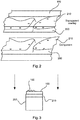
- Fig. 3 schematically shows a solid overlay for laser shock peening and a component to be treated by the laser shock peening according to an exemplary embodiment of the present invention.
- a solid overlay 100 for laser shock peening may comprise a transparent or translucent material, wherein the solid overlay 100 is structured and adapted to a shape 220 of a surface 210 of a component 200 to be treated by the laser shock peening.
- the solid overlay 100 may be configured to be producible by additive manufacturing, producible by liquid spraying, or by cutting processes.
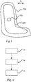
- Fig. 4 schematically shows a solid overlay for laser shock peening and a component to be treated by the laser shock peening according to an exemplary embodiment of the present invention.
- the component 200 may be separated from the solid overlay 100 by a threshold distance D.
- the threshold distance D may for instance be up to 2 ⁇ m, up to 10 ⁇ m or up to 100 ⁇ m or up to 1000 ⁇ m or up to 10 mm or up to 100 mm or up to 20 cm.
- the thickness of the transparent or the translucent overlay may be for instance without limitation between 2 ⁇ m and 25 000 ⁇ m or between 5 ⁇ m and 7500 ⁇ m or between 10 ⁇ m and 500 ⁇ m.
- Fig. 5 schematically shows a flow-chart diagram of a method for laser shock peening according to an exemplary embodiment of the present invention.
- the method may comprise the following steps of:
Landscapes
- Engineering & Computer Science (AREA)
- Physics & Mathematics (AREA)
- Optics & Photonics (AREA)
- Mechanical Engineering (AREA)
- Chemical & Material Sciences (AREA)
- Plasma & Fusion (AREA)
- Thermal Sciences (AREA)
- Crystallography & Structural Chemistry (AREA)
- Materials Engineering (AREA)
- Metallurgy (AREA)
- Organic Chemistry (AREA)
- Laser Beam Processing (AREA)
Abstract
Description
- The invention generally relates to a customised overlay material for plasma confinement for the processing of aircraft components by laser shock peening.
- In particular, the invention relates to a solid overlay for laser shock peening, a method for laser shock peening, and an aircraft component processed by laser shock peening.
- Laser shock peening is based on the coupling of high energy pulsed laser beams into materials or components whereby the propagation of shock waves is caused and, hence, a near-surface residual compressive stress is generated and material hardening is achieved.
-
US 4,937,421 describes a laser peening apparatus and method for peening a workpiece utilizing a laser beam. The therein described system includes a foil aligned with a surface of the workpiece to be peened. The therein described foil absorbs energy from the beam thereby the foil is vaporized creating a hot plasma. The plasma creates a shock wave which passes through the foil and peens the workpiece surface. - It is an object of the present invention to provide an improved laser shock peening process.
- This object is achieved by the subject-matter of the independent claims. Further exemplary embodiments are evident from the dependent claims and the following description.
- According to a first aspect of the present invention, a solid overlay for laser shock peening is provided, the solid overlay comprising: a transparent or translucent material, wherein the solid overlay is structured and adapted to a shape of a surface of a component to be treated by the laser shock peening.
- According to a further, second aspect, the present invention relates to a method for laser shock peening, the method comprising the steps of providing a component with a surface to be treated by the laser shock peening; providing a solid overlay on the surface, wherein the solid overlay comprises a transparent or translucent material, wherein the solid overlay is structured and adapted to a shape of the surface; and applying laser light to the component, wherein the laser light is transmitted through the solid overlay and absorbed at the surface, generating a plasma plume.
- According to a further, third aspect of the present invention, an aircraft component processed by a method according to the second aspect or according to any implementation of the second aspect is provided.
- In other words, for the laser shock peening process, the surface to be treated is covered with a transparent, solid layer, wherein this layer lets the laser beam pass through and provides that the laser beam hits afterwards the surface of the component to be treated, for instance the component is further covered with a protective, ablative layer such as a paint or a tape. The laser beam vaporizes material of the component at the surface or material from the protective or ablative layer and consequently a plasma plume is formed. The transparent or translucent overlay provides that the generated plasma is confined thereby enhancing the deforming effect of the plasma on the surface of the component to be treated.
- Without confining the generated plasma plume the high pressure plasma would reflect backwards into the air instead of travelling into the material and would create a high amplitude stress shock wave.
- As the stress wave propagates into the material, since it is reflected by the overlay, deformation is caused and thereby residual stress is generated which hardens the material.
- Using a solid, transparent or translucent overlay provides the advantage that the laser shock peening process can be used even if electrical systems are adjacent to the surface to be processed.
- The present invention provides a transparent or a translucent overlay to confine the plasma, wherein the transparent or translucent overlay is to be shaped to follow the contour of the surface of the component to be treated.
- The term "the solid overlay is structured and adapted to a shape of a surface of a component" as used by the present invention may be used to define that a certain shape or two-dimensional or three-dimensional contour of the surface of the component to be treated corresponds to the shape or in the two-dimensional contour or in the three-dimensional contour of the solid overlay. In other words, there may be a threshold distance for a minimal distance between the surface of the component to be treated and the contour of the solid overlay.
- The threshold distance may for instance be up to 2 µm, up to 10 µm or up to 100 µm or up to 1000 µm or up to 10 mm or up to 100 mm or up to 20 cm. The thickness of the transparent or the translucent overlay may be for instance without limitation between 2 µm and 25 000 µm or between 5 µm and 7500 µm or between 10 µm and 500 µm.
- According to an embodiment of the present invention, the solid overlay is configured to be producible by additive manufacturing. This advantageously allows synthesizing the solid overlay as a three-dimensional object based on three-dimensional printing, wherein successive layers of material are formed under computer control to create the solid overlay. Any kind of transparent or translucent polymer may be used for the three-dimensional printing process.
- According to another embodiment of the present invention, the solid overlay is configured to be producible by cutting processes. This advantageously allows easily cutting the solid overlay out of a bulk layer structure.
- According to another embodiment of the present invention, the solid overlay may further comprise a surface texture, wherein the surface texture is configured to adapt a pressure pulse transmitted to the surface of the component upon laser shock peening. This advantageously allows further adapting and adjusting the intensity of the surface treatment process. The used laser systems may be high energy, Nd-glass lasers producing pulse energies, for instance without limitation, up to 20 J or up to 40 J or up to 60 J. Pulse duration may be for instance without limitation between 2 ns and 200 µs or between 10 ns and 20 µs or between 20 ns and 100 ns.
- According to another exemplary embodiment of the present invention, the solid overlay is configured to confine a plasma plume generated by the laser light. This advantageously allows further controlling the laser shock peening process.
- According to another embodiment of the present invention, the solid overlay is configured to prevent backward reflections of the plasma plume with respect to the surface of the component. This advantageously allows further improving the laser shock peening process.
- According to another exemplary embodiment of the present invention, the solid overlay is configured to be coupled to the surface of the component. For instance, the solid overlay is a metallic layer and the solid overlay is coupled to the surface by an adjoining process.
- According to another embodiment of the present invention, the solid overlay is configured to be coupled to the surface of the component by a protective layer or by an ablative layer. The protective layer or the ablative layer may be a tape, for instance an adhesive tape.
- In general, the method describes a processing method for processing components used for aircraft. The method may also be used for processing components used for non-aircraft applications, for instance, components for marine vehicles, components for land vehicles, or for stationary machines or any further components.
-
-
Fig. 1 schematically shows an aircraft structure near to electrical systems inside cockpit areas according to an exemplary embodiment of the present invention. -
Fig. 2 schematically shows a perspective view of a component to be treated by laser shock peening according to an exemplary embodiment of the present invention. -
Fig. 3 schematically shows a solid overlay for laser shock peening and a component to be treated by the laser shock peening according to an exemplary embodiment of the present invention. -
Fig. 4 schematically shows a solid overlay for laser shock peening and a component to be treated by the laser shock peening according to an exemplary embodiment of the present invention. -
Fig. 5 schematically shows a flow-chart diagram of a method for laser shock peening according to an exemplary embodiment of the present invention. -
Fig. 1 shows an aircraft structure near to electrical systems inside cockpit areas according to an exemplary embodiment of the present invention. - Using a transparent or translucent overlay for the laser shock peening technique provides that the laser shock peening may be applied more effectively in aircraft manufacture.
- Using a transparent or translucent overlay allows removing the water layer that is currently applied ubiquitously in laser peening manufacturing. The water layer is usually applied by a nozzle, with the water running down the workpiece under gravity.
- With three-dimensonal, 3D, -printing or machining techniques, combined with detailed 3D-surface profilometry, a solid overlay material may be fabricated that would be a perfect match to any surface.
- The overlay may be formed with a textured surface in order to customise the pressure pulse profile into the material.
-
Fig. 1 shows the assembly of structural components of theaircraft fuselage 1 as the aircraft's main body section. Thecockpit 5 may comprisecomponents 200, which are located adjacent to electrical systems of the aircraft. - Using a solid, transparent or
translucent overlay 100 provides the advantage that the laser shock peening process can be used even if electrical systems are adjacent to the surface to be processed. - The term "transparent" as used by the present invention may refer to a physical property of allowing light to pass through the material without being scattered or absorbed. In other words, at least a certain threshold value, for instance more than 95 % of the incoming light may be allowed to pass through the material without being absorbed or scattered by the material.
- The term "translucent" as used by the present invention may refer to a physical property of allowing light to pass through the material without being absorbed. In other words, at least a certain threshold value, for instance more than 95 % of the incoming light may be allowed to pass through the material without being absorbed by the material.
- In other words, a translucent medium allows the transport of light while a transparent medium not only allows the transport of light but allows for image formation.
-
Fig. 2 schematically shows a perspective view of a component to be treated by laser shock peening according to an exemplary embodiment of the present invention. - A
solid overlay 100 for laser shock peening may be deposited on top of asurface 210 of acomponent 200 to be treated by the laser shock peening. Without thesolid overlay 100, theplasma plume 230 would not be confined and would not shift from the surface and, lowering the peak pressure. - The laser shock peening, LSP, method may be based on the coupling of high energy pulsed laser beams into materials or
components 200, generating a propagation of shock waves and, hence, of near-surface residual compressive stresses and hardening of thesurface 210 or of surface-near parts - up to several mm of structural depth depending on the energy applied - of the bulk material of thecomponent 200. - The laser used for the laser shock peening may for instance be a pulsed Nd:YAG laser or a laser with 1054 nm wavelength and 2 - 20 ns laser pulse length.
-
Fig. 3 schematically shows a solid overlay for laser shock peening and a component to be treated by the laser shock peening according to an exemplary embodiment of the present invention. - A
solid overlay 100 for laser shock peening may comprise a transparent or translucent material, wherein thesolid overlay 100 is structured and adapted to ashape 220 of asurface 210 of acomponent 200 to be treated by the laser shock peening. - The
solid overlay 100 may be configured to be producible by additive manufacturing, producible by liquid spraying, or by cutting processes. -
Fig. 4 schematically shows a solid overlay for laser shock peening and a component to be treated by the laser shock peening according to an exemplary embodiment of the present invention. - The
component 200, or theshape 220 of the component, may be separated from thesolid overlay 100 by a threshold distance D. - The threshold distance D may for instance be up to 2 µm, up to 10 µm or up to 100 µm or up to 1000 µm or up to 10 mm or up to 100 mm or up to 20 cm. The thickness of the transparent or the translucent overlay may be for instance without limitation between 2 µm and 25 000 µm or between 5 µm and 7500 µm or between 10 µm and 500 µm.
-
Fig. 5 schematically shows a flow-chart diagram of a method for laser shock peening according to an exemplary embodiment of the present invention. - The method may comprise the following steps of:
- As a first step of the method, providing S1 a
component 200 with asurface 210 to be treated by the laser shock peening may be performed. - As a second step of the method, providing S2 a
solid overlay 100 on thesurface 210 may be performed, wherein thesolid overlay 100 comprises a transparent or translucent material, wherein thesolid overlay 100 is structured and adapted to ashape 220 of thesurface 210. - As a third step of the method, applying S3 laser light to the
component 200 may be conducted, wherein the laser light is transmitted through thesolid overlay 100 and absorbed at thesurface 210, generating aplasma plume 230. - While the invention has been illustrated and described in detail in the drawings and the foregoing description, such illustration and description are to be considered illustrative and exemplary and not restrictive; the invention is not limited to the disclosed embodiments.
- Other variations to the disclosed embodiments can be understood and effected by those skilled in the art and practicing the claimed invention, from a study of the drawings, the disclosure, and the appended clams. In the claims the term "comprising" does not exclude other elements, and the indefinite article "a" or "an" does not exclude a plurality.
- The mere fact that certain measures are recited in mutually different claims does not indicate that a combination of these measures cannot be used to advantage. Any reference signs in the claims should not be construed as limiting the scope of protection.
Claims (14)
- A solid overlay (100) for laser shock peening, the solid overlay (100) comprising:a transparent or translucent material, wherein the solid overlay (100) is structured and adapted to a shape (220) of a surface (210) of a component (200) to be treated by the laser shock peening.
- The solid overlay (100) according to claim 1,
wherein the solid overlay (100) is configured to be producible by additive manufacturing. - The solid overlay (100) according to anyone of the preceding claims,
wherein the solid overlay (100) is configured to be producible by cutting processes. - The solid overlay (100) according to anyone of the preceding claims, further comprising a surface texture (102), which is configured to adapt a pressure pulse transmitted to the surface (210) of the component (200) upon laser shock peening.
- The solid overlay (100) according to anyone of the preceding claims,
wherein the solid overlay (100) is configured to confine a plasma plume (230) generated by laser light. - The solid overlay (100) according to claim 5,
wherein the solid overlay (100) is configured to prevent backward reflections of the plasma plume (230) with respect to the surface (210) of the component (200). - The solid overlay (100) according to anyone of the preceding claims,
wherein the solid overlay (100) is configured to be coupled to the surface (210) of the component (200). - The solid overlay (100) according to claim 7,
wherein the solid overlay (100) is configured to be coupled to the surface (210) of the component (200) by a protective layer or by a ablative layer. - Use of the solid overlay (100) according to anyone of the preceding claims for laser shock peening.
- A method for laser shock peening, the method comprising the steps of- Providing (S1) a component (200) with a surface (210) to be treated by the laser shock peening;- Providing (S2) a solid overlay (100) on the surface (210), wherein the solid overlay (100) comprise a transparent or translucent material, wherein the solid overlay (100) is structured and adapted to a shape (220) of the surface (210); and- Applying (S3) laser light to the component (200), wherein the laser light is transmitted through the solid overlay (100) and absorbed at the surface (210), generating a plasma plume.
- The method according to claim 10,
wherein the solid overlay (100) is produced by additive manufacturing. - The method according to anyone of the preceding claims 10 to 11,
wherein the solid overlay (100) is produced by cutting processes. - The method according to anyone of the preceding claims 10 to 12,
wherein a surface texture (102) of the solid overlay (100) adapts a pressure pulse transmitted to the surface (210) of the component (200) upon laser shock peening. - Aircraft component processed by a method according to one of claims 10 to 13.
Priority Applications (2)
| Application Number | Priority Date | Filing Date | Title |
|---|---|---|---|
| EP16154216.2A EP3202523B1 (en) | 2016-02-04 | 2016-02-04 | Overlay material for laser shock peening |
| US15/422,939 US20170225266A1 (en) | 2016-02-04 | 2017-02-02 | Overlay Material For Laser Shock Peening |
Applications Claiming Priority (1)
| Application Number | Priority Date | Filing Date | Title |
|---|---|---|---|
| EP16154216.2A EP3202523B1 (en) | 2016-02-04 | 2016-02-04 | Overlay material for laser shock peening |
Publications (2)
| Publication Number | Publication Date |
|---|---|
| EP3202523A1 true EP3202523A1 (en) | 2017-08-09 |
| EP3202523B1 EP3202523B1 (en) | 2019-04-03 |
Family
ID=55304900
Family Applications (1)
| Application Number | Title | Priority Date | Filing Date |
|---|---|---|---|
| EP16154216.2A Active EP3202523B1 (en) | 2016-02-04 | 2016-02-04 | Overlay material for laser shock peening |
Country Status (2)
| Country | Link |
|---|---|
| US (1) | US20170225266A1 (en) |
| EP (1) | EP3202523B1 (en) |
Families Citing this family (1)
| Publication number | Priority date | Publication date | Assignee | Title |
|---|---|---|---|---|
| CN119589118B (en) * | 2024-12-26 | 2025-12-26 | 上海交通大学 | A Laser Shock-Based Additive Manufacturing Method |
Citations (4)
| Publication number | Priority date | Publication date | Assignee | Title |
|---|---|---|---|---|
| US4937421A (en) | 1989-07-03 | 1990-06-26 | General Electric Company | Laser peening system and method |
| FR2709762A1 (en) * | 1993-09-07 | 1995-03-17 | Aerospatiale | Process for the application of laser pulses to a crystalline solid material |
| US5744781A (en) * | 1995-08-07 | 1998-04-28 | General Electric Company | Method and apparatus for laser shock peening |
| US6057003A (en) * | 1995-10-23 | 2000-05-02 | Lsp Technologies, Inc. | Peening process with reduction of dielectric breakdown to increase peak pressure pulse |
Family Cites Families (1)
| Publication number | Priority date | Publication date | Assignee | Title |
|---|---|---|---|---|
| US8049137B2 (en) * | 2004-02-13 | 2011-11-01 | Boston Scientific Scimed, Inc. | Laser shock peening of medical devices |
-
2016
- 2016-02-04 EP EP16154216.2A patent/EP3202523B1/en active Active
-
2017
- 2017-02-02 US US15/422,939 patent/US20170225266A1/en not_active Abandoned
Patent Citations (4)
| Publication number | Priority date | Publication date | Assignee | Title |
|---|---|---|---|---|
| US4937421A (en) | 1989-07-03 | 1990-06-26 | General Electric Company | Laser peening system and method |
| FR2709762A1 (en) * | 1993-09-07 | 1995-03-17 | Aerospatiale | Process for the application of laser pulses to a crystalline solid material |
| US5744781A (en) * | 1995-08-07 | 1998-04-28 | General Electric Company | Method and apparatus for laser shock peening |
| US6057003A (en) * | 1995-10-23 | 2000-05-02 | Lsp Technologies, Inc. | Peening process with reduction of dielectric breakdown to increase peak pressure pulse |
Also Published As
| Publication number | Publication date |
|---|---|
| US20170225266A1 (en) | 2017-08-10 |
| EP3202523B1 (en) | 2019-04-03 |
Similar Documents
| Publication | Publication Date | Title |
|---|---|---|
| EP2986410B1 (en) | Process diagnostic system for and method of performing laser shock peening on a target with a fluid flow path sandwiched beteen a transparent to laser light solid medium and the target | |
| CN1228460C (en) | Metal shaping by laser hardening | |
| US7507312B2 (en) | Using laser shock loads to debond structures | |
| US20180361509A1 (en) | Powder-Bed-Based Additive Manufacturing Method With Surface Post-Treatment | |
| US20170057014A1 (en) | Additive manufacturing | |
| GB2541810B (en) | Additive Manufacturing | |
| CN106893855B (en) | A kind of leading two-sided asynchronous excitation impact reinforcing method in side of turbo blade | |
| US11638970B2 (en) | Enhanced material shock using spatiotemporal laser pulse formatting | |
| US10189117B2 (en) | Adhesion improvement via material nanostructuring or texturizing | |
| US20230219294A1 (en) | Hybrid additive manufacturing method | |
| JP6547933B2 (en) | Laser processing method for fiber reinforced composite material and laser processing apparatus therefor | |
| US20110290770A1 (en) | Method for preventing crack formation and for slowing down the advancement of a crack in metal aircraft structures by means of laser shock rays | |
| EP3202523B1 (en) | Overlay material for laser shock peening | |
| JP2006061966A (en) | Method of preventing stress corrosion cracking associated with cold working of steel and alloy steel including stainless steel using fs (femtosecond) ultrashort pulse kW class high average power laser | |
| US10035577B2 (en) | Reinforced vehicle structural part and vehicle | |
| JP5172191B2 (en) | Laser shock hardening processing method and laser shock hardening processing apparatus | |
| Don-Liyanage et al. | Schlieren imaging of laser-generated ultrasound | |
| WO2023101861A3 (en) | Systems and methods for fabricating an article with an angled edge using a laser beam focal line | |
| Kugotova et al. | Processes of Poly (Methyl Methacrylate) Destruction by High-Speed Impact and Pulse Laser Action: A Comparative Analysis | |
| METSIOS | Q-switch laser surface refurbishment of sea vessels | |
| Balasubramanian Nagarajana et al. | The Effects of Ablative Coating Thickness at Various Laser Intensities and Multiple Laser Pulses in High-Strain-Rate Laser Shock Forming of Thin Copper Sheet | |
| Gilath et al. | Behavior of materials at dynamic stress conditions using laser-induced shock waves | |
| Feit et al. | Importance of free surfaces for damage crater formation | |
| Napadłek et al. | Ablative laser cleaning of lacquer coating |
Legal Events
| Date | Code | Title | Description |
|---|---|---|---|
| PUAI | Public reference made under article 153(3) epc to a published international application that has entered the european phase |
Free format text: ORIGINAL CODE: 0009012 |
|
| STAA | Information on the status of an ep patent application or granted ep patent |
Free format text: STATUS: THE APPLICATION HAS BEEN PUBLISHED |
|
| AK | Designated contracting states |
Kind code of ref document: A1 Designated state(s): AL AT BE BG CH CY CZ DE DK EE ES FI FR GB GR HR HU IE IS IT LI LT LU LV MC MK MT NL NO PL PT RO RS SE SI SK SM TR |
|
| AX | Request for extension of the european patent |
Extension state: BA ME |
|
| STAA | Information on the status of an ep patent application or granted ep patent |
Free format text: STATUS: REQUEST FOR EXAMINATION WAS MADE |
|
| 17P | Request for examination filed |
Effective date: 20180209 |
|
| RBV | Designated contracting states (corrected) |
Designated state(s): AL AT BE BG CH CY CZ DE DK EE ES FI FR GB GR HR HU IE IS IT LI LT LU LV MC MK MT NL NO PL PT RO RS SE SI SK SM TR |
|
| REG | Reference to a national code |
Ref country code: DE Ref legal event code: R079 Ref document number: 602016011727 Country of ref document: DE Free format text: PREVIOUS MAIN CLASS: B23K0026000000 Ipc: B23K0026356000 |
|
| GRAP | Despatch of communication of intention to grant a patent |
Free format text: ORIGINAL CODE: EPIDOSNIGR1 |
|
| STAA | Information on the status of an ep patent application or granted ep patent |
Free format text: STATUS: GRANT OF PATENT IS INTENDED |
|
| RIC1 | Information provided on ipc code assigned before grant |
Ipc: B23K 101/00 20060101ALI20180903BHEP Ipc: B23K 26/00 20140101ALI20180903BHEP Ipc: B23K 26/356 20140101AFI20180903BHEP Ipc: C21D 10/00 20060101ALI20180903BHEP |
|
| INTG | Intention to grant announced |
Effective date: 20181002 |
|
| GRAS | Grant fee paid |
Free format text: ORIGINAL CODE: EPIDOSNIGR3 |
|
| GRAA | (expected) grant |
Free format text: ORIGINAL CODE: 0009210 |
|
| STAA | Information on the status of an ep patent application or granted ep patent |
Free format text: STATUS: THE PATENT HAS BEEN GRANTED |
|
| AK | Designated contracting states |
Kind code of ref document: B1 Designated state(s): AL AT BE BG CH CY CZ DE DK EE ES FI FR GB GR HR HU IE IS IT LI LT LU LV MC MK MT NL NO PL PT RO RS SE SI SK SM TR |
|
| REG | Reference to a national code |
Ref country code: GB Ref legal event code: FG4D |
|
| REG | Reference to a national code |
Ref country code: CH Ref legal event code: EP Ref country code: AT Ref legal event code: REF Ref document number: 1115129 Country of ref document: AT Kind code of ref document: T Effective date: 20190415 |
|
| REG | Reference to a national code |
Ref country code: DE Ref legal event code: R096 Ref document number: 602016011727 Country of ref document: DE |
|
| REG | Reference to a national code |
Ref country code: IE Ref legal event code: FG4D |
|
| REG | Reference to a national code |
Ref country code: NL Ref legal event code: MP Effective date: 20190403 |
|
| REG | Reference to a national code |
Ref country code: LT Ref legal event code: MG4D |
|
| REG | Reference to a national code |
Ref country code: AT Ref legal event code: MK05 Ref document number: 1115129 Country of ref document: AT Kind code of ref document: T Effective date: 20190403 |
|
| PG25 | Lapsed in a contracting state [announced via postgrant information from national office to epo] |
Ref country code: NL Free format text: LAPSE BECAUSE OF FAILURE TO SUBMIT A TRANSLATION OF THE DESCRIPTION OR TO PAY THE FEE WITHIN THE PRESCRIBED TIME-LIMIT Effective date: 20190403 |
|
| PG25 | Lapsed in a contracting state [announced via postgrant information from national office to epo] |
Ref country code: FI Free format text: LAPSE BECAUSE OF FAILURE TO SUBMIT A TRANSLATION OF THE DESCRIPTION OR TO PAY THE FEE WITHIN THE PRESCRIBED TIME-LIMIT Effective date: 20190403 Ref country code: NO Free format text: LAPSE BECAUSE OF FAILURE TO SUBMIT A TRANSLATION OF THE DESCRIPTION OR TO PAY THE FEE WITHIN THE PRESCRIBED TIME-LIMIT Effective date: 20190703 Ref country code: LT Free format text: LAPSE BECAUSE OF FAILURE TO SUBMIT A TRANSLATION OF THE DESCRIPTION OR TO PAY THE FEE WITHIN THE PRESCRIBED TIME-LIMIT Effective date: 20190403 Ref country code: PT Free format text: LAPSE BECAUSE OF FAILURE TO SUBMIT A TRANSLATION OF THE DESCRIPTION OR TO PAY THE FEE WITHIN THE PRESCRIBED TIME-LIMIT Effective date: 20190803 Ref country code: AL Free format text: LAPSE BECAUSE OF FAILURE TO SUBMIT A TRANSLATION OF THE DESCRIPTION OR TO PAY THE FEE WITHIN THE PRESCRIBED TIME-LIMIT Effective date: 20190403 Ref country code: ES Free format text: LAPSE BECAUSE OF FAILURE TO SUBMIT A TRANSLATION OF THE DESCRIPTION OR TO PAY THE FEE WITHIN THE PRESCRIBED TIME-LIMIT Effective date: 20190403 Ref country code: SE Free format text: LAPSE BECAUSE OF FAILURE TO SUBMIT A TRANSLATION OF THE DESCRIPTION OR TO PAY THE FEE WITHIN THE PRESCRIBED TIME-LIMIT Effective date: 20190403 Ref country code: CZ Free format text: LAPSE BECAUSE OF FAILURE TO SUBMIT A TRANSLATION OF THE DESCRIPTION OR TO PAY THE FEE WITHIN THE PRESCRIBED TIME-LIMIT Effective date: 20190403 Ref country code: HR Free format text: LAPSE BECAUSE OF FAILURE TO SUBMIT A TRANSLATION OF THE DESCRIPTION OR TO PAY THE FEE WITHIN THE PRESCRIBED TIME-LIMIT Effective date: 20190403 |
|
| PG25 | Lapsed in a contracting state [announced via postgrant information from national office to epo] |
Ref country code: RS Free format text: LAPSE BECAUSE OF FAILURE TO SUBMIT A TRANSLATION OF THE DESCRIPTION OR TO PAY THE FEE WITHIN THE PRESCRIBED TIME-LIMIT Effective date: 20190403 Ref country code: PL Free format text: LAPSE BECAUSE OF FAILURE TO SUBMIT A TRANSLATION OF THE DESCRIPTION OR TO PAY THE FEE WITHIN THE PRESCRIBED TIME-LIMIT Effective date: 20190403 Ref country code: GR Free format text: LAPSE BECAUSE OF FAILURE TO SUBMIT A TRANSLATION OF THE DESCRIPTION OR TO PAY THE FEE WITHIN THE PRESCRIBED TIME-LIMIT Effective date: 20190704 Ref country code: BG Free format text: LAPSE BECAUSE OF FAILURE TO SUBMIT A TRANSLATION OF THE DESCRIPTION OR TO PAY THE FEE WITHIN THE PRESCRIBED TIME-LIMIT Effective date: 20190703 Ref country code: LV Free format text: LAPSE BECAUSE OF FAILURE TO SUBMIT A TRANSLATION OF THE DESCRIPTION OR TO PAY THE FEE WITHIN THE PRESCRIBED TIME-LIMIT Effective date: 20190403 |
|
| PG25 | Lapsed in a contracting state [announced via postgrant information from national office to epo] |
Ref country code: AT Free format text: LAPSE BECAUSE OF FAILURE TO SUBMIT A TRANSLATION OF THE DESCRIPTION OR TO PAY THE FEE WITHIN THE PRESCRIBED TIME-LIMIT Effective date: 20190403 Ref country code: IS Free format text: LAPSE BECAUSE OF FAILURE TO SUBMIT A TRANSLATION OF THE DESCRIPTION OR TO PAY THE FEE WITHIN THE PRESCRIBED TIME-LIMIT Effective date: 20190803 |
|
| REG | Reference to a national code |
Ref country code: DE Ref legal event code: R097 Ref document number: 602016011727 Country of ref document: DE |
|
| PG25 | Lapsed in a contracting state [announced via postgrant information from national office to epo] |
Ref country code: EE Free format text: LAPSE BECAUSE OF FAILURE TO SUBMIT A TRANSLATION OF THE DESCRIPTION OR TO PAY THE FEE WITHIN THE PRESCRIBED TIME-LIMIT Effective date: 20190403 Ref country code: RO Free format text: LAPSE BECAUSE OF FAILURE TO SUBMIT A TRANSLATION OF THE DESCRIPTION OR TO PAY THE FEE WITHIN THE PRESCRIBED TIME-LIMIT Effective date: 20190403 Ref country code: DK Free format text: LAPSE BECAUSE OF FAILURE TO SUBMIT A TRANSLATION OF THE DESCRIPTION OR TO PAY THE FEE WITHIN THE PRESCRIBED TIME-LIMIT Effective date: 20190403 Ref country code: SK Free format text: LAPSE BECAUSE OF FAILURE TO SUBMIT A TRANSLATION OF THE DESCRIPTION OR TO PAY THE FEE WITHIN THE PRESCRIBED TIME-LIMIT Effective date: 20190403 |
|
| PLBE | No opposition filed within time limit |
Free format text: ORIGINAL CODE: 0009261 |
|
| STAA | Information on the status of an ep patent application or granted ep patent |
Free format text: STATUS: NO OPPOSITION FILED WITHIN TIME LIMIT |
|
| PG25 | Lapsed in a contracting state [announced via postgrant information from national office to epo] |
Ref country code: IT Free format text: LAPSE BECAUSE OF FAILURE TO SUBMIT A TRANSLATION OF THE DESCRIPTION OR TO PAY THE FEE WITHIN THE PRESCRIBED TIME-LIMIT Effective date: 20190403 Ref country code: SM Free format text: LAPSE BECAUSE OF FAILURE TO SUBMIT A TRANSLATION OF THE DESCRIPTION OR TO PAY THE FEE WITHIN THE PRESCRIBED TIME-LIMIT Effective date: 20190403 |
|
| 26N | No opposition filed |
Effective date: 20200106 |
|
| PG25 | Lapsed in a contracting state [announced via postgrant information from national office to epo] |
Ref country code: TR Free format text: LAPSE BECAUSE OF FAILURE TO SUBMIT A TRANSLATION OF THE DESCRIPTION OR TO PAY THE FEE WITHIN THE PRESCRIBED TIME-LIMIT Effective date: 20190403 |
|
| PG25 | Lapsed in a contracting state [announced via postgrant information from national office to epo] |
Ref country code: SI Free format text: LAPSE BECAUSE OF FAILURE TO SUBMIT A TRANSLATION OF THE DESCRIPTION OR TO PAY THE FEE WITHIN THE PRESCRIBED TIME-LIMIT Effective date: 20190403 |
|
| REG | Reference to a national code |
Ref country code: CH Ref legal event code: PL |
|
| REG | Reference to a national code |
Ref country code: BE Ref legal event code: MM Effective date: 20200229 |
|
| PG25 | Lapsed in a contracting state [announced via postgrant information from national office to epo] |
Ref country code: MC Free format text: LAPSE BECAUSE OF FAILURE TO SUBMIT A TRANSLATION OF THE DESCRIPTION OR TO PAY THE FEE WITHIN THE PRESCRIBED TIME-LIMIT Effective date: 20190403 Ref country code: LU Free format text: LAPSE BECAUSE OF NON-PAYMENT OF DUE FEES Effective date: 20200204 |
|
| PG25 | Lapsed in a contracting state [announced via postgrant information from national office to epo] |
Ref country code: CH Free format text: LAPSE BECAUSE OF NON-PAYMENT OF DUE FEES Effective date: 20200229 Ref country code: LI Free format text: LAPSE BECAUSE OF NON-PAYMENT OF DUE FEES Effective date: 20200229 |
|
| PG25 | Lapsed in a contracting state [announced via postgrant information from national office to epo] |
Ref country code: IE Free format text: LAPSE BECAUSE OF NON-PAYMENT OF DUE FEES Effective date: 20200204 Ref country code: FR Free format text: LAPSE BECAUSE OF NON-PAYMENT OF DUE FEES Effective date: 20200229 |
|
| PG25 | Lapsed in a contracting state [announced via postgrant information from national office to epo] |
Ref country code: BE Free format text: LAPSE BECAUSE OF NON-PAYMENT OF DUE FEES Effective date: 20200229 |
|
| PG25 | Lapsed in a contracting state [announced via postgrant information from national office to epo] |
Ref country code: MT Free format text: LAPSE BECAUSE OF FAILURE TO SUBMIT A TRANSLATION OF THE DESCRIPTION OR TO PAY THE FEE WITHIN THE PRESCRIBED TIME-LIMIT Effective date: 20190403 Ref country code: CY Free format text: LAPSE BECAUSE OF FAILURE TO SUBMIT A TRANSLATION OF THE DESCRIPTION OR TO PAY THE FEE WITHIN THE PRESCRIBED TIME-LIMIT Effective date: 20190403 |
|
| PG25 | Lapsed in a contracting state [announced via postgrant information from national office to epo] |
Ref country code: MK Free format text: LAPSE BECAUSE OF FAILURE TO SUBMIT A TRANSLATION OF THE DESCRIPTION OR TO PAY THE FEE WITHIN THE PRESCRIBED TIME-LIMIT Effective date: 20190403 |
|
| PGFP | Annual fee paid to national office [announced via postgrant information from national office to epo] |
Ref country code: GB Payment date: 20260219 Year of fee payment: 11 |
|
| PGFP | Annual fee paid to national office [announced via postgrant information from national office to epo] |
Ref country code: DE Payment date: 20260218 Year of fee payment: 11 |