EP3202516A1 - Chuck structure - Google Patents
Chuck structure Download PDFInfo
- Publication number
- EP3202516A1 EP3202516A1 EP15845959.4A EP15845959A EP3202516A1 EP 3202516 A1 EP3202516 A1 EP 3202516A1 EP 15845959 A EP15845959 A EP 15845959A EP 3202516 A1 EP3202516 A1 EP 3202516A1
- Authority
- EP
- European Patent Office
- Prior art keywords
- chuck
- workpiece
- leaf spring
- members
- pressing
- Prior art date
- Legal status (The legal status is an assumption and is not a legal conclusion. Google has not performed a legal analysis and makes no representation as to the accuracy of the status listed.)
- Granted
Links
Images



Classifications
-
- B—PERFORMING OPERATIONS; TRANSPORTING
- B23—MACHINE TOOLS; METAL-WORKING NOT OTHERWISE PROVIDED FOR
- B23B—TURNING; BORING
- B23B31/00—Chucks; Expansion mandrels; Adaptations thereof for remote control
- B23B31/02—Chucks
- B23B31/10—Chucks characterised by the retaining or gripping devices or their immediate operating means
- B23B31/12—Chucks with simultaneously-acting jaws, whether or not also individually adjustable
- B23B31/1207—Chucks with simultaneously-acting jaws, whether or not also individually adjustable moving obliquely to the axis of the chuck in a plane containing this axis
- B23B31/1253—Jaws movement actuated by an axially movable member
-
- B—PERFORMING OPERATIONS; TRANSPORTING
- B23—MACHINE TOOLS; METAL-WORKING NOT OTHERWISE PROVIDED FOR
- B23B—TURNING; BORING
- B23B31/00—Chucks; Expansion mandrels; Adaptations thereof for remote control
- B23B31/02—Chucks
- B23B31/10—Chucks characterised by the retaining or gripping devices or their immediate operating means
- B23B31/117—Retention by friction only, e.g. using springs, resilient sleeves, tapers
- B23B31/1173—Retention by friction only, e.g. using springs, resilient sleeves, tapers using springs
-
- B—PERFORMING OPERATIONS; TRANSPORTING
- B23—MACHINE TOOLS; METAL-WORKING NOT OTHERWISE PROVIDED FOR
- B23B—TURNING; BORING
- B23B31/00—Chucks; Expansion mandrels; Adaptations thereof for remote control
- B23B31/02—Chucks
- B23B31/10—Chucks characterised by the retaining or gripping devices or their immediate operating means
- B23B31/117—Retention by friction only, e.g. using springs, resilient sleeves, tapers
-
- B—PERFORMING OPERATIONS; TRANSPORTING
- B23—MACHINE TOOLS; METAL-WORKING NOT OTHERWISE PROVIDED FOR
- B23B—TURNING; BORING
- B23B31/00—Chucks; Expansion mandrels; Adaptations thereof for remote control
- B23B31/40—Expansion mandrels
- B23B31/4006—Gripping the work or tool by a split sleeve
-
- B—PERFORMING OPERATIONS; TRANSPORTING
- B23—MACHINE TOOLS; METAL-WORKING NOT OTHERWISE PROVIDED FOR
- B23B—TURNING; BORING
- B23B31/00—Chucks; Expansion mandrels; Adaptations thereof for remote control
- B23B31/40—Expansion mandrels
- B23B31/404—Gripping the work or tool by jaws moving radially controlled by conical surfaces
-
- B—PERFORMING OPERATIONS; TRANSPORTING
- B23—MACHINE TOOLS; METAL-WORKING NOT OTHERWISE PROVIDED FOR
- B23B—TURNING; BORING
- B23B31/00—Chucks; Expansion mandrels; Adaptations thereof for remote control
- B23B31/40—Expansion mandrels
- B23B31/42—Expansion mandrels characterised by features relating primarily to remote control of the gripping means
-
- B—PERFORMING OPERATIONS; TRANSPORTING
- B24—GRINDING; POLISHING
- B24B—MACHINES, DEVICES, OR PROCESSES FOR GRINDING OR POLISHING; DRESSING OR CONDITIONING OF ABRADING SURFACES; FEEDING OF GRINDING, POLISHING, OR LAPPING AGENTS
- B24B41/00—Component parts such as frames, beds, carriages, headstocks
- B24B41/06—Work supports, e.g. adjustable steadies
- B24B41/061—Work supports, e.g. adjustable steadies axially supporting turning workpieces, e.g. magnetically, pneumatically
-
- B—PERFORMING OPERATIONS; TRANSPORTING
- B24—GRINDING; POLISHING
- B24B—MACHINES, DEVICES, OR PROCESSES FOR GRINDING OR POLISHING; DRESSING OR CONDITIONING OF ABRADING SURFACES; FEEDING OF GRINDING, POLISHING, OR LAPPING AGENTS
- B24B41/00—Component parts such as frames, beds, carriages, headstocks
- B24B41/06—Work supports, e.g. adjustable steadies
- B24B41/067—Work supports, e.g. adjustable steadies radially supporting workpieces
-
- B—PERFORMING OPERATIONS; TRANSPORTING
- B23—MACHINE TOOLS; METAL-WORKING NOT OTHERWISE PROVIDED FOR
- B23B—TURNING; BORING
- B23B2260/00—Details of constructional elements
- B23B2260/136—Springs
-
- B—PERFORMING OPERATIONS; TRANSPORTING
- B23—MACHINE TOOLS; METAL-WORKING NOT OTHERWISE PROVIDED FOR
- B23B—TURNING; BORING
- B23B31/00—Chucks; Expansion mandrels; Adaptations thereof for remote control
- B23B31/02—Chucks
- B23B31/08—Chucks holding tools yieldably
-
- Y—GENERAL TAGGING OF NEW TECHNOLOGICAL DEVELOPMENTS; GENERAL TAGGING OF CROSS-SECTIONAL TECHNOLOGIES SPANNING OVER SEVERAL SECTIONS OF THE IPC; TECHNICAL SUBJECTS COVERED BY FORMER USPC CROSS-REFERENCE ART COLLECTIONS [XRACs] AND DIGESTS
- Y10—TECHNICAL SUBJECTS COVERED BY FORMER USPC
- Y10T—TECHNICAL SUBJECTS COVERED BY FORMER US CLASSIFICATION
- Y10T279/00—Chucks or sockets
- Y10T279/10—Expanding
- Y10T279/1037—Axially moving actuator
- Y10T279/1041—Wedge
- Y10T279/1045—Internal cone
-
- Y—GENERAL TAGGING OF NEW TECHNOLOGICAL DEVELOPMENTS; GENERAL TAGGING OF CROSS-SECTIONAL TECHNOLOGIES SPANNING OVER SEVERAL SECTIONS OF THE IPC; TECHNICAL SUBJECTS COVERED BY FORMER USPC CROSS-REFERENCE ART COLLECTIONS [XRACs] AND DIGESTS
- Y10—TECHNICAL SUBJECTS COVERED BY FORMER USPC
- Y10T—TECHNICAL SUBJECTS COVERED BY FORMER US CLASSIFICATION
- Y10T279/00—Chucks or sockets
- Y10T279/10—Expanding
- Y10T279/1037—Axially moving actuator
- Y10T279/1041—Wedge
- Y10T279/1054—Wedge with resilient means contacting nonresilient jaw
-
- Y—GENERAL TAGGING OF NEW TECHNOLOGICAL DEVELOPMENTS; GENERAL TAGGING OF CROSS-SECTIONAL TECHNOLOGIES SPANNING OVER SEVERAL SECTIONS OF THE IPC; TECHNICAL SUBJECTS COVERED BY FORMER USPC CROSS-REFERENCE ART COLLECTIONS [XRACs] AND DIGESTS
- Y10—TECHNICAL SUBJECTS COVERED BY FORMER USPC
- Y10T—TECHNICAL SUBJECTS COVERED BY FORMER US CLASSIFICATION
- Y10T279/00—Chucks or sockets
- Y10T279/17—Socket type
- Y10T279/17411—Spring biased jaws
- Y10T279/17461—Nonresilient member biased by a resilient member
-
- Y—GENERAL TAGGING OF NEW TECHNOLOGICAL DEVELOPMENTS; GENERAL TAGGING OF CROSS-SECTIONAL TECHNOLOGIES SPANNING OVER SEVERAL SECTIONS OF THE IPC; TECHNICAL SUBJECTS COVERED BY FORMER USPC CROSS-REFERENCE ART COLLECTIONS [XRACs] AND DIGESTS
- Y10—TECHNICAL SUBJECTS COVERED BY FORMER USPC
- Y10T—TECHNICAL SUBJECTS COVERED BY FORMER US CLASSIFICATION
- Y10T279/00—Chucks or sockets
- Y10T279/17—Socket type
- Y10T279/17411—Spring biased jaws
- Y10T279/17487—Moving-cam actuator
- Y10T279/17521—Reciprocating cam sleeve
Definitions
- the present invention relates to a chuck structure, which is configured to chuck an annular workpiece from a radially outer side of the workpiece in a machine tool such as a grinding machine.
- Patent Literature 1 an outer diameter collet chuck which includes a collet having a plurality of gripping claws arranged along a circumferential direction of the collet.
- an outer surface on a distal end side of each of the gripping claws is formed into a tapered surface tapered from a distal end side of each of the gripping claws to a proximal end side thereof, and a radially inner surface of a cylindrical part, which is arranged on an outer peripheral side of each of the gripping claws, is formed into a tapered surface tapered from a distal end side of the cylindrical part to a proximal end side thereof.
- Patent Literature 2 there can be proposed the device configured to clamp the workpiece by the pair of leaf spring members. That is, the device has the structure of clamping the workpiece by the opposing two leaf spring members.
- Patent Literature 2 is configured to chuck a minute workpiece. Accordingly, it is structurally difficult to employ the device disclosed in Patent Literature 2 to chuck the workpiece on a main spindle of a machine tool configured to perform working on an annular workpiece having a large diameter.
- the present invention has been made in view of the above-mentioned problems, and has an object to provide a chuck structure capable of stably chucking an annular workpiece without deforming the workpiece.
- a chuck structure which is configured to chuck an annular workpiece from a radially outer side of the workpiece, comprising: leaf spring members arranged at a predetermined pitch along a circumferential direction of the chuck structure so as to be symmetrical with respect to a mechanism center axis; chuck claw members mounted to distal ends of the leaf spring members, respectively; and a pressing force applying mechanism configured to apply a force of pressing the leaf spring members radially inward, to thereby elastically press the chuck claw members onto a radially outer surface of the workpiece.
- a chucking force of elastically pressing the chuck clawmembers onto the radially outer surface of the workpiece can be applied through the pressing force applying mechanism.
- the workpiece can be chucked from the radially outer surface side of the workpiece.
- the chuck claw members are arranged at a predetermined pitch along the circumferential direction so as to be symmetrical with respect to the mechanism center axis. Accordingly, even when each of the chuck claw members exerts a small pressing force on the radially outer surface of the workpiece, the chuck structure can stably chuck the workpiece.
- Each of the leaf spring members is arranged in an oblique posture so that a distal end side of the each of the leaf spring members is directed radially outward.
- the pressing force applying mechanism comprises a pressing member to be brought into contact with a radially outer side of the each of the leaf spring members.
- the chuck claw members can be tightened and loosened by up-and-down movement of the pressing member.
- the chuck claw members respectively mounted to the leaf spring members can be tightened and loosened in a radial direction by up-and-down movement of the pressing member. Accordingly, a moving amount of each of the chuck claw members during a shift from a chucked state to an unchucked state or during a shift from the unchucked state to the chucked state can be stably secured.
- the pressing member comprise a plurality of pressing members arranged to correspond to the leaf spring members, respectively, and that the plurality of pressing members be moved up and down in synchronization with each other.
- the chuck claw members are tightened and loosened in the radial direction in synchronization with each other.
- the chuck structure further comprise: a first vertically-movable shaft configured to hold the leaf spring members; a second vertically-movable shaft configured to hold the pressing member; and a vertically moving mechanism configured to vertically move the first vertically-movable shaft and the second vertically-movable shaft independently of each other.
- the leaf spring members and the pressing members can be moved up and down at the same time by the same amount, or the leaf spring members and the pressing members can be moved up and down separately by the same amount or different amounts.
- the chuck structure may further comprise a backing plate that forms a positioning reference surface for the workpiece, wherein, under a state in which the leaf spring members chuck the workpiece, simultaneous and relative movement of the first vertically-movable shaft and the second vertically-movable shaft with respect to the backing plate enables a lower end surface of the workpiece to be pressed onto the backing plate.
- the chuck structure can be used to chuck the workpiece on a rotary spindle of a machine tool, and can be used for, for example, a grinding machine, as the machine tool.
- a chuck structure which is configured to chuck an annular workpiece from a radially inner side of the workpiece, comprising: leaf spring members arranged at a predetermined pitch along a circumferential direction of the chuck structure so as to be symmetrical with respect to a mechanism center axis; chuck claw members mounted to distal ends of the leaf spring members, respectively; and a pressing force applying mechanism configured to apply a force of pressing the leaf spring members radially outward, to thereby elastically press the chuck claw members onto a radially inner surface of the workpiece.
- a chucking force of elastically pressing the chuck clawmembers onto the radially inner surface of the workpiece can be applied through the pressing force applying mechanism.
- the workpiece can be chucked from the radially inner surface side of the workpiece.
- the chuck claw members are arranged at a predetermined pitch along the circumferential direction so as to be symmetrical with respect to the mechanism center axis. Accordingly, even when each of the chuck claw members exerts a small pressing force on the radially inner surface of the workpiece, the chuck structure can stably chuck the workpiece.
- the chuck structure according to the first aspect of the present invention can stably chuck the workpiece.
- the chuck structure can stably chuck the workpiece without deforming the workpiece.
- each of the leaf spring members there is used a leaf spring member arranged in an oblique posture so that a distal end side of the leaf spring member is directed radially outward.
- a moving amount of each of the chuck claw members during a shift from a chucked state to an unchucked state or during a shift from the unchucked state to the chucked state can be stably secured.
- a relatively large moving amount is secured as the moving amount of each of the chuck claw members . Accordingly, even when a circularity of the radially outer surface of the workpiece is somewhat poor, the workpiece can be chucked with less influence on deformation. Further, accuracy of loading is not required.
- the chuck claw members are tightened and loosened in the radial direction in synchronization with each other, thereby being capable of chucking the workpiece with high accuracy.
- the leaf spring members and the pressing members can be moved up and down at the same time by the same amount, or the leaf spring members and the pressing members can be moved up and down separately by the same amount or different amounts.
- a chucking force can be freely changed by freely varying a shifting amount of the leaf spring members.
- the chuck structure comprises the backing plate
- the workpiece can be stably seated on the backing plate.
- working on the workpiece through use of a machine tool such as a grinding machine employing the above-mentioned chuck structure can be performed with high accuracy.
- the chuck structure according to the second aspect of the present invention can stably chuck the workpiece.
- the chuck structure can stably chuck the workpiece without deforming the workpiece.
- a chuck structure according to the present invention is a chuck structure configured to chuck an annular workpiece W from a radially outer side of the workpiece W.
- the chuck structure is arranged on a first vertically-movable shaft 1 and a second vertically-movable shaft 2 that are mounted to a rotary spindle 3 of a machine tool such as a grinding machine.
- the first vertically-movable shaft 1 comprises a base shaft 4 formed of a tubular body, and a distal end boss section 5 formed continuously with a distal end (upper end) of the base shaft 4.
- the distal end boss section 5 comprises a main body portion 5a, and a tubular portion 5b extending in a suspended manner from a lower surface of the main body portion 5a.
- a hole, which is to be communicated to the tubular portion 5b, is formed in the lower surface of the main body portion 5a. That is, the tubular portion 5b and the hole define a fitting hole 6 into which the second vertically-movable shaft 2 is to be fitted.
- a lower end surface 7 of the tubular portion 5b of the distal end boss section 5 is placed on an upper end surface 8 of the base shaft 4, and screw members 9 are inserted through the distal end boss section 5 to be respectively screwed into screw holes 10 formed in the upper end surface 8 of the base shaft 4.
- the base shaft 4 and the distal end boss section 5 are integrated with each other.
- the second vertically-movable shaft 2 is fitted into the fitting hole 6 or an inside of the base shaft 4 formed of the tubular body.
- a spacer 11 is interposed between the first vertically-movable shaft 1 and the second vertically-movable shaft 2, and the first vertically-movable shaft 1 and the second vertically-movable shaft 2 are vertically moved along an axial direction of each shaft relative to each other. That is, the first vertically-movable shaft 1 and the second vertically-movable shaft 2 are vertically moved along a direction of an axial center of each shaft independent of each other. In this case, the first vertically-movable shaft 1 and the second vertically-movable shaft 2 can be vertically moved by a key-and-keyway mechanism (not shown) relative to each other, but are restrained from rotating relative to each other.
- the first vertically-movable shaft 1 is fitted into the rotary spindle 3 through intermediation of a spacer 12.
- the rotary spindle 3 comprises a tubular main body 13, and a receiving chamber section 14.
- the receiving chamber section 14 is formed continuously with an upper portion of the main body 13, and is formed of a short tubular portion having a large diameter.
- the receiving chamber section 14 comprises a disc portion 14a and a ring portion 14b having a large diameter.
- the disc portion 14a is coupled to an upper end of the tubular main body 13 with a bolt member 15.
- the ring portion 14b is coupled to the disc portion 14a with bolt members 16.
- a clearance 18 is defined between a radially outer surface of the main body portion 5a and a radially inner surface of the ring portion 14b of the receiving chamber section 14.
- a backing plate 19 is formed on the rotary spindle 3. That is, an inner flange portion 20 is formed on an upper opening of the receiving chamber section 14, and six through-holes 20a are formed in the inner flange portion 20 at positions corresponding to leaf spring members 21 to be described later, that is, at a 60-degree pitch along a circumferential direction of the rotary spindle 3.
- the backing plate 19 is formed of an inner peripheral edge of the inner flange portion 20.
- the rotary spindle 3 and the first vertically-movable shaft 1 can be vertically moved by a key-and-keyway mechanism (not shown) relative to each other, but are restrained from rotating relative to each other. Accordingly, when the rotary spindle 3 is driven to rotate about an axial center thereof, the first vertically-movable shaft 1 and the second vertically-movable shaft 2 are rotated in synchronization with the rotary spindle 3.
- the rotary spindle 3 can be driven to rotate about the axial center thereof by a rotary drive mechanism (not shown). Further, the first vertically-movable shaft 1 and the second vertically-movable shaft 2 can be vertically moved independently of each other by a vertically moving mechanism (not shown) . In this case, the first vertically-movable shaft 1 and the second vertically-movable shaft 2 can be vertically moved by separate drive sources independent of each other. However, even when the chuck structure comprises the above-mentioned separate drive sources, the first vertically-movable shaft 1 and the second vertically-movable shaft 2 can be vertically moved in synchronization with each other.
- the rotary spindle 3 is restrained from reciprocating in an axial center direction thereof. That is, the rotary spindle 3 is allowed by a bearing mechanism (not shown) only to rotate about the axial center thereof.
- the chuck structure according to the present invention comprises the leaf spring members 21 arranged at a predetermined pitch along the circumferential direction so as to be symmetrical with respect to a mechanism center axis, chuck clawmembers 22 mounted to distal ends of the leaf spring members 21, respectively, and a pressing force applying mechanism 23 configured to apply a force of pressing the leaf spring members 21 radially inward, to thereby elastically press the chuck claw members 22 onto a radially outer surface Wa of the workpiece W.
- a swelling portion 25 is formed on an outer peripheral portion of a lower end of the distal end boss section 5.
- the swelling portion 25 may be formed of a ring portion formed along the circumferential direction, or six protruding portions formed at a 60-degree pitch along the circumferential direction so as to correspond to the leaf spring members 21.
- an outer surface of the swelling portion 25 is formed of a tapered surface 25a tapered from an upper side to a lower side thereof. Accordingly, under a state in which the tapered surface 25a and a retaining piece 26 clamp a lower end of each leaf spring member 21, the retaining piece 26 is mounted to the swelling portion 25 with a bolt member 27. Accordingly, as illustrated in FIG. 2A , in a free state, each leaf spring member 21 is arranged in an oblique posture so that a distal end side of the leaf spring member 21 is directed radially outward.
- a distal end of the chuck claw member 22 mounted to the distal end of each leaf spring member 21 is formed as a frictional resistance increasing portion 22a.
- the frictional resistance increasing portion 22a can be formed of a member comprising an uneven and rubbed surface, a member comprising a resin layer formed on a surface thereof, or a member having a large coefficient of friction.
- the frictional resistance increasing portion 22a is held in surface contact (surface press-contact) with the radially outer surface Wa of the workpiece W.
- the retaining piece 28 is mounted to the chuck claw member 22 with a bolt member 29.
- the pressing force applying mechanism 23 comprises pressing members 30 each formed of a round bar with a small length.
- the pressing members 30 are moved up and down (vertically moved) with respect to the first vertically-movable shaft 1.
- the pressing members 30 are held on a holding frame body 32 mounted to the second vertically-movable shaft 2.
- An axial length of each of the pressing members 30 is set to be substantially equal to a width dimension of each of the leaf spring members 21.
- the expression “substantially equal” means that the axial length of each pressing member 30 may be equal to the width dimension of each leaf spring member 21, that the axial length of each pressing member 30 may be slightly larger than the width dimension of each leaf spring member 21, and that the axial length of each pressing member 30 may be slightly smaller than the width dimension of each leaf spring member 21.
- the holding frame body 32 comprises a ring body 33, and a fixed portion 34 fixed to the upper end surface of the second vertically-movable shaft 2 with bolt members 35.
- a protruding portion 2a is formed on a center portion of the upper end surface of the second vertically-movable shaft 2, and a through-hole 34a is formed in the fixed portion 34.
- the protruding portion 2a formed on the center portion of the upper end surface of the second vertically-movable shaft 2 is fitted into the through-hole 34a of the fixed portion 34.
- the fixed portion 34 is formed of a plate-like member, and is fitted into a slit 36 formed in the distal end boss section 5 of the first vertically-movable shaft 1.
- Each of the pressing members 30 is held on the ring body 33 by a holding member 37 mounted to the ring body 33.
- the holding member 37 comprises a block body 40 and a screw member 41.
- the block body 40 has an engagement piece portion 40a formed at a distal end of the block body 40.
- the screw member 41 is configured to mount the block body 40 to the ring body 33.
- the engagement piece portion 40a comprises an inner inclined surface 42a and an outer inclined surface 42b, and is gradually reduced in thickness toward a tip thereof.
- the inner inclined surface 42a of the engagement piece portion 40a of the pressing members 30 retains the holding member 37.
- the pressing members 30 is supported on the ring body 33.
- a part of each of the pressing members 30 protrudes from a distal edge of the engagement piece portion 40a of the holding member 37 to the distal end boss section 5 side of the first vertically-movable shaft 1.
- An inclination of the outer inclined surface 42b of the engagement piece portion 40a of the holding member 37 is set to such an angle as to prevent the outer inclined surface 42b from coming into contact with the leaf spring member 21.
- adjusting members 45 are screwed into the ring body 33.
- the adjusting members 45 are each formed of a setscrew, and are configured to adjust protruding amounts of the pressing members 30 to the distal end boss section 5 side. That is, the adjusting members 45 are turned in a tightening or loosening direction, thereby being capable of adjusting the protruding amounts of the pressing members 30.
- This adjusting mechanism is arranged because intervals between the leaf spring members 21 and the pressing members 30 vary due to component accuracy and assembly accuracy.
- Each pressing member 30 is held in contact with each leaf spring member 21 under the state illustrated in FIG. 2A , that is, under a state in which the leaf spring member 21 extends straight.
- the pressing member 30 is raised.
- the pressing member 30 presses a center portion of the leaf spring member 21 in a length direction of the leaf spring member 21 to the distal end boss section 5 side.
- the chuck claw member 22 presses the radially outer surface Wa of the workpiece W in a direction indicated by the arrow F.
- the pressing member 30 is moved to a side opposite to the distal end boss section, thereby being capable of cancelling the pressing force applied from the chuck claw member 22 to the radially outer surface Wa of the workpiece W.
- the leaf spring member 21 is tilted radially outward so that the chuck claw member 22 is moved away from the radially outer surface Wa of the workpiece W.
- the ring body 33 is lowered with respect to the first vertically-movable shaft 1. That is, the second vertically-movable shaft 2 is lowered with respect to the first vertically-movable shaft 1.
- the pressing members 30 are held in contact with the leaf spring members 21, respectively, and a diameter of an arc, which is formed by an inner surface of each of the plurality of chuck claw members 22, is set to be larger than a diameter of the radially outer surface Wa of the workpiece W.
- a clearance is defined between the frictional resistance increasing portions 22a of the plurality of chuck claw members 22 and the radially outer surface Wa of the workpiece W.
- the workpiece W is easily arranged within the plurality of chuck claw members 22.
- the leaf spring members 21 can be pressed by the pressing members 30 to the radially inner side, that is, to the distal end boss section 5 side of the first vertically-movable shaft 1, and the chuck claw members 22 can apply the pressing force to the radially outer surface Wa of the workpiece W.
- the workpiece W is chucked by the chuck structure. That is, the workpiece W is brought into the state illustrated in FIG. 4 .
- the first vertically-movable shaft 1 and the second vertically-movable shaft 2 are lowered with respect to the rotary spindle 3 by an amount of ⁇ 2 (see FIG. 5 ).
- the workpiece W can be reliably seated on the backing plate 19. There is a fear in that the workpiece W is inclined with respect to the backing plate 19 depending on an arrangement way of the workpiece.
- the ring body 33 is lowered with respect to the first vertically-movable shaft 1 by the amount of ⁇ 1 from the state illustrated in FIG. 1 to lower the pressing members 30 with respect to the first vertically-movable shaft 1, the pressing of the workpiece W by the chuck claw members 22 can be cancelled. Further, when the first vertically-movable shaft 1 and the second vertically-movable shaft 2 are raised by the amount of ⁇ 2 afterward, the chuck structure can be returned to the state illustrated in FIG. 3 .
- a chucking force of elastically pressing the chuck claw members 22 onto the radially outer surface Wa of the workpiece W can be applied through the pressing force applying mechanism 23.
- the workpiece W can be chucked from the radially outer surface Wa side.
- the chuck claw members 22 are arranged at a predetermined pitch along the circumferential direction so as to be symmetrical with respect to the mechanism center axis. Accordingly, even when each of the chuck claw members 22 exerts a small pressing force on the radially outer surface Wa of the workpiece W, the chuck structure can stably chuck the workpiece W. Thus, even when the workpiece W is thin and annular, the chuck structure can stably chuck the workpiece W without deforming the workpiece W.
- each of the leaf spring members 21 there is used a leaf spring member arranged in an oblique posture so that a distal end side of the leaf spring member is directed radially outward.
- a moving amount of each chuck claw member 22 during a shift from a chucked state to an unchucked state or during a shifted from the unchucked state to the chucked state can be stably secured.
- a relatively large moving amount is secured as the moving amount of the chuck claw member 22. Accordingly, even when a circularity of the radially outer surface Wa of the workpiece W is somewhat poor, there is less influence on deformation, and accuracy of loading is not required.
- the pressing members 30 can be moved up and down in synchronization with each other. Accordingly, the chuck claw members 22 are tightened and loosened in a radial direction in synchronization with each other, thereby being capable of chucking the workpiece with high accuracy.
- the leaf spring members 21 and the pressing members 30 can be moved up and down at the same time by the same amount, or the leaf spring members 21 and the pressing members 30 can be moved up and down separately by the same amount or different amounts .
- the chucking force can be freely changed by freely varying a shifting amount of the leaf spring members.
- the workpiece W can be stably seated on the backing plate 19.
- working on the workpiece through use of a machine tool such as a grinding machine employing the chuck structure can be performed with high accuracy.
- the pressing members 30 are held in contact with the leaf spring members 21 even when the workpiece is unchucked.
- the leaf spring members 21 and the chuck claw members 22 can be prevented from behaving unstably due to, for example, working fluid or a centrifugal force generated by rotation of the rotary spindle.
- a surface of each chuck claw member 22 to be brought into contact with the workpiece is formed as the frictional resistance increasing portion 22a.
- the chuck claw members 22 can exert more stable chucking force.
- the force of pressing the workpiece W by the chuck claw members 22 can be increased.
- the pressing force of the chuck claw members 22 with respect to the workpiece W can be reduced. Accordingly, during working and the like, the chucking force applied to the workpiece W can be changed in accordance with working efficiency.
- the present invention is described above. However, the present invention is not limited to the above-mentioned embodiment, and various modifications may be made thereto.
- the leaf spring members 21 each comprising the chuck clawmember 22 six leaf springmembers are used in the above-mentioned embodiment. However, the number of the leaf spring members may be increased or reduced as appropriate. It is only necessary that at least three leaf spring members be arranged at a 120-degree pitch along the circumferential direction.
- a length dimension, a width dimension, and a thickness dimension of each leaf spring member 21, an inclination angle of the leaf spring member in a free state, and the like can be set as appropriate as long as the leaf spring member 21 can be pressed by the pressing member 30 and can be tightened and loosened by up-and-down movement of the pressing member 30 and as long as the chuck claw member 22 can press the radially outer surface Wa of the workpiece W.
- the chuck structure chucks the annular workpiece from the radially outer side of the workpiece.
- the chuck structure may chuck the annular workpiece from a radially inner side of the workpiece.
- the chuck structure may comprise leaf spring members arranged at a predetermined pitch along a circumferential direction of the chuck structure so as to be symmetrical with respect to a mechanism center axis, chuck claw members mounted to distal ends of the leaf spring members, respectively, and a pressing force applying mechanism configured to apply a force of pressing the leaf spring members radially outward, to thereby elastically press the chuck clawmembers onto a radially inner surface of the workpiece.
- the chuck structure configured to chuck the annular workpiece from the radially inner side of the workpiece, a chucking force of elastically pressing the chuck clawmembers onto the radially inner surface of the workpiece can be applied through the pressing force applying mechanism.
- the chuck claw members are arranged at a predetermined pitch along the circumferential direction so as to be symmetrical with respect to the mechanism center axis. Accordingly, even when each of the chuck claw members exerts a small pressing force on the radially inner surface of the workpiece, the chuck structure can stably chuck the workpiece.
- the chuck structure can stably chuck the workpiece without deforming the workpiece.
- the chuck structure according to the invention of the subject application comprises leaf spring members arranged at a predetermined pitch along a circumferential direction of the chuck structure so as to be symmetrical with respect to a mechanism center axis, chuck claw members mounted to distal ends of the leaf spring members, respectively, and a pressing force applying mechanism configured to apply a force of pressing the leaf spring members, to thereby elastically press the chuck claw members onto the workpiece.
- the pressing force applying mechanism applies the force of pressing the leaf spring members radially inward or radially outward, to thereby elastically press the chuck claw members onto a radially outer surface or a radially inner surface of the workpiece.
- each of the pressing members 30, in addition to the round bar a member having another shape such as a spherical shape may be used.
- the chuck structure according to the present invention may be used not only for a grinding machine but also for various machine tools such as a lathe, a drilling machine, and a milling machine.
Landscapes
- Engineering & Computer Science (AREA)
- Mechanical Engineering (AREA)
- Gripping On Spindles (AREA)
- Jigs For Machine Tools (AREA)
- Grinding Of Cylindrical And Plane Surfaces (AREA)
Abstract
Description
- The present invention relates to a chuck structure, which is configured to chuck an annular workpiece from a radially outer side of the workpiece in a machine tool such as a grinding machine.
- Hitherto, as a chuck structure of this type, there has been known an outer diameter collet chuck which includes a collet having a plurality of gripping claws arranged along a circumferential direction of the collet (Patent Literature 1) . That is, in the outer diameter collet chuck, an outer surface on a distal end side of each of the gripping claws is formed into a tapered surface tapered from a distal end side of each of the gripping claws to a proximal end side thereof, and a radially inner surface of a cylindrical part, which is arranged on an outer peripheral side of each of the gripping claws, is formed into a tapered surface tapered from a distal end side of the cylindrical part to a proximal end side thereof. Accordingly, the gripping claws are tightened and loosened through reciprocation in an axial direction. Thus, the gripping claws can chuck a workpiece from a radially outer side of the workpiece.
- Further, hitherto, there has been known a chuck device using a pair of leaf spring members, though the chuck device is not configured to chuck an annular workpiece (Patent Literature 2) . That is, the pair of leaf spring members clamps the workpiece.
-
- Patent Literature 1:
JP 08-19908 A - Patent Literature 2:
JP 2002-292590 A - In the outer diameter collet chuck disclosed in
Patent Literature 1, there is a fear in that a radially outer surface of the workpiece may be chucked with an excessively large force. Accordingly, even if working is intended to be performed on the workpiece with high accuracy, e.g., working accuracy of 1/1000 mm through use of the outer diameter collet chuck disclosed inPatent Literature 1, when the outer diameter collet chuck chucks an annular workpiece, in particular, a thin and annular workpiece, there is a fear in that the workpiece is deformed by being chucked so that the working accuracy is degraded. - Accordingly, it is necessary to chuck the thin and annular workpiece with a relatively small force. In this context, as disclosed in
Patent Literature 2, there can be proposed the device configured to clamp the workpiece by the pair of leaf spring members. That is, the device has the structure of clamping the workpiece by the opposing two leaf spring members. - However, when the workpiece is chucked by the two leaf spring members, the workpiece cannot be held satisfactorily in a radial direction. Further, the device disclosed in
Patent Literature 2 is configured to chuck a minute workpiece. Accordingly, it is structurally difficult to employ the device disclosed inPatent Literature 2 to chuck the workpiece on a main spindle of a machine tool configured to perform working on an annular workpiece having a large diameter. - The present invention has been made in view of the above-mentioned problems, and has an object to provide a chuck structure capable of stably chucking an annular workpiece without deforming the workpiece.
- According to a first aspect of the present invention, there is provided a chuck structure, which is configured to chuck an annular workpiece from a radially outer side of the workpiece, comprising: leaf spring members arranged at a predetermined pitch along a circumferential direction of the chuck structure so as to be symmetrical with respect to a mechanism center axis; chuck claw members mounted to distal ends of the leaf spring members, respectively; and a pressing force applying mechanism configured to apply a force of pressing the leaf spring members radially inward, to thereby elastically press the chuck claw members onto a radially outer surface of the workpiece.
- According to the chuck structure of the first aspect of the present invention, a chucking force of elastically pressing the chuck clawmembers onto the radially outer surface of the workpiece can be applied through the pressing force applying mechanism. Thus, the workpiece can be chucked from the radially outer surface side of the workpiece. In addition, the chuck claw members are arranged at a predetermined pitch along the circumferential direction so as to be symmetrical with respect to the mechanism center axis. Accordingly, even when each of the chuck claw members exerts a small pressing force on the radially outer surface of the workpiece, the chuck structure can stably chuck the workpiece.
- Each of the leaf spring members is arranged in an oblique posture so that a distal end side of the each of the leaf spring members is directed radially outward. The pressing force applying mechanism comprises a pressing member to be brought into contact with a radially outer side of the each of the leaf spring members. The chuck claw members can be tightened and loosened by up-and-down movement of the pressing member. With this configuration, the chuck claw members respectively mounted to the leaf spring members can be tightened and loosened in a radial direction by up-and-down movement of the pressing member. Accordingly, a moving amount of each of the chuck claw members during a shift from a chucked state to an unchucked state or during a shift from the unchucked state to the chucked state can be stably secured.
- It is preferred that the pressing member comprise a plurality of pressing members arranged to correspond to the leaf spring members, respectively, and that the plurality of pressing members be moved up and down in synchronization with each other. When the pressing members are moved up and down in synchronization with each other, the chuck claw members are tightened and loosened in the radial direction in synchronization with each other.
- It is preferred that the chuck structure further comprise: a first vertically-movable shaft configured to hold the leaf spring members; a second vertically-movable shaft configured to hold the pressing member; and a vertically moving mechanism configured to vertically move the first vertically-movable shaft and the second vertically-movable shaft independently of each other. With this configuration, the leaf spring members and the pressing members can be moved up and down at the same time by the same amount, or the leaf spring members and the pressing members can be moved up and down separately by the same amount or different amounts.
- The chuck structure may further comprise a backing plate that forms a positioning reference surface for the workpiece, wherein, under a state in which the leaf spring members chuck the workpiece, simultaneous and relative movement of the first vertically-movable shaft and the second vertically-movable shaft with respect to the backing plate enables a lower end surface of the workpiece to be pressed onto the backing plate.
- The chuck structure can be used to chuck the workpiece on a rotary spindle of a machine tool, and can be used for, for example, a grinding machine, as the machine tool.
- According to a second aspect of the present invention, there is provided a chuck structure, which is configured to chuck an annular workpiece from a radially inner side of the workpiece, comprising: leaf spring members arranged at a predetermined pitch along a circumferential direction of the chuck structure so as to be symmetrical with respect to a mechanism center axis; chuck claw members mounted to distal ends of the leaf spring members, respectively; and a pressing force applying mechanism configured to apply a force of pressing the leaf spring members radially outward, to thereby elastically press the chuck claw members onto a radially inner surface of the workpiece.
- According to the chuck structure of the second aspect of the present invention, a chucking force of elastically pressing the chuck clawmembers onto the radially inner surface of the workpiece can be applied through the pressing force applying mechanism. Thus, the workpiece can be chucked from the radially inner surface side of the workpiece. In addition, the chuck claw members are arranged at a predetermined pitch along the circumferential direction so as to be symmetrical with respect to the mechanism center axis. Accordingly, even when each of the chuck claw members exerts a small pressing force on the radially inner surface of the workpiece, the chuck structure can stably chuck the workpiece.
- Even when each of the chuck claw members exerts a small pressing force on the radially outer surface of the workpiece, the chuck structure according to the first aspect of the present invention can stably chuck the workpiece. Thus, even when the workpiece is thin and annular, the chuck structure can stably chuck the workpiece without deforming the workpiece.
- As each of the leaf spring members, there is used a leaf spring member arranged in an oblique posture so that a distal end side of the leaf spring member is directed radially outward. With this configuration, a moving amount of each of the chuck claw members during a shift from a chucked state to an unchucked state or during a shift from the unchucked state to the chucked state can be stably secured. In addition, a relatively large moving amount is secured as the moving amount of each of the chuck claw members . Accordingly, even when a circularity of the radially outer surface of the workpiece is somewhat poor, the workpiece can be chucked with less influence on deformation. Further, accuracy of loading is not required.
- When the pressing members can be moved up and down in synchronization with each other, the chuck claw members are tightened and loosened in the radial direction in synchronization with each other, thereby being capable of chucking the workpiece with high accuracy. When the first vertically-movable shaft and the second vertically-movable shaft can be vertically moved independently of each other, the leaf spring members and the pressing members can be moved up and down at the same time by the same amount, or the leaf spring members and the pressing members can be moved up and down separately by the same amount or different amounts. Thus, a chucking force can be freely changed by freely varying a shifting amount of the leaf spring members.
- When the chuck structure comprises the backing plate, the workpiece can be stably seated on the backing plate. Thus, working on the workpiece through use of a machine tool such as a grinding machine employing the above-mentioned chuck structure can be performed with high accuracy.
- Even when each of the chuck claw members exerts a small pressing force on the radially inner surface of the workpiece, the chuck structure according to the second aspect of the present invention can stably chuck the workpiece. Thus, even when the workpiece is thin and annular, the chuck structure can stably chuck the workpiece without deforming the workpiece.
-
-
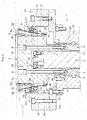
FIG. 1 is a sectional view for illustrating relevant parts of a chuck structure according to the present invention. -
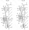
FIG. 2A is an enlarged view for illustrating a relationship between leaf spring members and a pressing force applying mechanism before a workpiece is chucked. -
FIG. 2B is an enlarged view for illustrating a relationship between the leaf spring members and the pressing force applying mechanism under a state in which the workpiece is chucked. -
FIG. 3 is a sectional view for illustrating a state after the workpiece is arranged (before the workpiece is chucked). -
FIG. 4 is a sectional view for illustrating a state in which only a second vertically-movable shaft is raised from the state illustrated inFIG. 3 . -
FIG. 5 is a sectional view for illustrating a relationship among the state illustrated inFIG. 1 , the state illustrated inFIG. 3 , and the state illustrated inFIG. 4 . - Now, an embodiment of the present invention is described with reference to
FIG. 1 to FIG. 5 . A chuck structure according to the present invention is a chuck structure configured to chuck an annular workpiece W from a radially outer side of the workpiece W. The chuck structure is arranged on a first vertically-movable shaft 1 and a second vertically-movable shaft 2 that are mounted to arotary spindle 3 of a machine tool such as a grinding machine. - The first vertically-
movable shaft 1 comprises abase shaft 4 formed of a tubular body, and a distalend boss section 5 formed continuously with a distal end (upper end) of thebase shaft 4. The distalend boss section 5 comprises amain body portion 5a, and atubular portion 5b extending in a suspended manner from a lower surface of themain body portion 5a. A hole, which is to be communicated to thetubular portion 5b, is formed in the lower surface of themain body portion 5a. That is, thetubular portion 5b and the hole define afitting hole 6 into which the second vertically-movable shaft 2 is to be fitted. - In this case, a
lower end surface 7 of thetubular portion 5b of the distalend boss section 5 is placed on anupper end surface 8 of thebase shaft 4, andscrew members 9 are inserted through the distalend boss section 5 to be respectively screwed into screw holes 10 formed in theupper end surface 8 of thebase shaft 4. In this manner, thebase shaft 4 and the distalend boss section 5 are integrated with each other. Further, the second vertically-movable shaft 2 is fitted into thefitting hole 6 or an inside of thebase shaft 4 formed of the tubular body. - A
spacer 11 is interposed between the first vertically-movable shaft 1 and the second vertically-movable shaft 2, and the first vertically-movable shaft 1 and the second vertically-movable shaft 2 are vertically moved along an axial direction of each shaft relative to each other. That is, the first vertically-movable shaft 1 and the second vertically-movable shaft 2 are vertically moved along a direction of an axial center of each shaft independent of each other. In this case, the first vertically-movable shaft 1 and the second vertically-movable shaft 2 can be vertically moved by a key-and-keyway mechanism (not shown) relative to each other, but are restrained from rotating relative to each other. - The first vertically-
movable shaft 1 is fitted into therotary spindle 3 through intermediation of aspacer 12. In this case, therotary spindle 3 comprises a tubularmain body 13, and a receivingchamber section 14. The receivingchamber section 14 is formed continuously with an upper portion of themain body 13, and is formed of a short tubular portion having a large diameter. The receivingchamber section 14 comprises adisc portion 14a and aring portion 14b having a large diameter. Thedisc portion 14a is coupled to an upper end of the tubularmain body 13 with abolt member 15. Thering portion 14b is coupled to thedisc portion 14a withbolt members 16. That is, themain body portion 5a of the distalend boss section 5 of the first vertically-movable shaft 1 is received in the receivingchamber section 14 of therotary spindle 3. In this case, aclearance 18 is defined between a radially outer surface of themain body portion 5a and a radially inner surface of thering portion 14b of the receivingchamber section 14. - Further, a
backing plate 19 is formed on therotary spindle 3. That is, aninner flange portion 20 is formed on an upper opening of the receivingchamber section 14, and six through-holes 20a are formed in theinner flange portion 20 at positions corresponding toleaf spring members 21 to be described later, that is, at a 60-degree pitch along a circumferential direction of therotary spindle 3. Thebacking plate 19 is formed of an inner peripheral edge of theinner flange portion 20. - The
rotary spindle 3 and the first vertically-movable shaft 1 can be vertically moved by a key-and-keyway mechanism (not shown) relative to each other, but are restrained from rotating relative to each other. Accordingly, when therotary spindle 3 is driven to rotate about an axial center thereof, the first vertically-movable shaft 1 and the second vertically-movable shaft 2 are rotated in synchronization with therotary spindle 3. - The
rotary spindle 3 can be driven to rotate about the axial center thereof by a rotary drive mechanism (not shown). Further, the first vertically-movable shaft 1 and the second vertically-movable shaft 2 can be vertically moved independently of each other by a vertically moving mechanism (not shown) . In this case, the first vertically-movable shaft 1 and the second vertically-movable shaft 2 can be vertically moved by separate drive sources independent of each other. However, even when the chuck structure comprises the above-mentioned separate drive sources, the first vertically-movable shaft 1 and the second vertically-movable shaft 2 can be vertically moved in synchronization with each other. Therotary spindle 3 is restrained from reciprocating in an axial center direction thereof. That is, therotary spindle 3 is allowed by a bearing mechanism (not shown) only to rotate about the axial center thereof. - The chuck structure according to the present invention comprises the
leaf spring members 21 arranged at a predetermined pitch along the circumferential direction so as to be symmetrical with respect to a mechanism center axis, chuckclawmembers 22 mounted to distal ends of theleaf spring members 21, respectively, and a pressingforce applying mechanism 23 configured to apply a force of pressing theleaf spring members 21 radially inward, to thereby elastically press thechuck claw members 22 onto a radially outer surface Wa of the workpiece W. - In this case, six
leaf spring members 21 are arranged at a 60-degree pitch along the circumferential direction on the distalend boss section 5 of the second vertically-movable shaft 2. That is, a swellingportion 25 is formed on an outer peripheral portion of a lower end of the distalend boss section 5. The swellingportion 25 may be formed of a ring portion formed along the circumferential direction, or six protruding portions formed at a 60-degree pitch along the circumferential direction so as to correspond to theleaf spring members 21. - As illustrated in
FIG. 2A and FIG. 2B , an outer surface of the swellingportion 25 is formed of atapered surface 25a tapered from an upper side to a lower side thereof. Accordingly, under a state in which the taperedsurface 25a and a retainingpiece 26 clamp a lower end of eachleaf spring member 21, the retainingpiece 26 is mounted to the swellingportion 25 with abolt member 27. Accordingly, as illustrated inFIG. 2A , in a free state, eachleaf spring member 21 is arranged in an oblique posture so that a distal end side of theleaf spring member 21 is directed radially outward. - A distal end of the
chuck claw member 22 mounted to the distal end of eachleaf spring member 21 is formed as a frictionalresistance increasing portion 22a. In this case, the frictionalresistance increasing portion 22a can be formed of a member comprising an uneven and rubbed surface, a member comprising a resin layer formed on a surface thereof, or a member having a large coefficient of friction. When the workpiece is chucked, the frictionalresistance increasing portion 22a is held in surface contact (surface press-contact) with the radially outer surface Wa of the workpiece W. In this case, under a state in which a back taperedsurface 22b of thechuck claw member 22 and a retainingpiece 28 clamp an upper end of eachleaf spring member 21, the retainingpiece 28 is mounted to thechuck claw member 22 with abolt member 29. - The pressing
force applying mechanism 23 comprises pressingmembers 30 each formed of a round bar with a small length. Thepressing members 30 are moved up and down (vertically moved) with respect to the first vertically-movable shaft 1. In this case, under a state in which each of thepressing members 30 is arranged so that an axis thereof is parallel to a direction orthogonal to an axis of the first vertically-movable shaft 1 and an axis of the second vertically-movable shaft 2, thepressing members 30 are held on a holdingframe body 32 mounted to the second vertically-movable shaft 2. An axial length of each of thepressing members 30 is set to be substantially equal to a width dimension of each of theleaf spring members 21. Herein, the expression "substantially equal" means that the axial length of each pressingmember 30 may be equal to the width dimension of eachleaf spring member 21, that the axial length of each pressingmember 30 may be slightly larger than the width dimension of eachleaf spring member 21, and that the axial length of each pressingmember 30 may be slightly smaller than the width dimension of eachleaf spring member 21. - As illustrated in
FIG. 1 , the holdingframe body 32 comprises aring body 33, and a fixedportion 34 fixed to the upper end surface of the second vertically-movable shaft 2 withbolt members 35. A protrudingportion 2a is formed on a center portion of the upper end surface of the second vertically-movable shaft 2, and a through-hole 34a is formed in the fixedportion 34. The protrudingportion 2a formed on the center portion of the upper end surface of the second vertically-movable shaft 2 is fitted into the through-hole 34a of the fixedportion 34. Further, the fixedportion 34 is formed of a plate-like member, and is fitted into aslit 36 formed in the distalend boss section 5 of the first vertically-movable shaft 1. - Each of the
pressing members 30 is held on thering body 33 by a holdingmember 37 mounted to thering body 33. In this case, as illustrated inFIG. 2A and FIG. 2B ,cutout portions 38 are formed on a radially inner side of thering body 33, and thepressing members 30 are fitted into thecutout portions 38, respectively. The holdingmember 37 comprises ablock body 40 and ascrew member 41. Theblock body 40 has anengagement piece portion 40a formed at a distal end of theblock body 40. Thescrew member 41 is configured to mount theblock body 40 to thering body 33. Theengagement piece portion 40a comprises an innerinclined surface 42a and an outerinclined surface 42b, and is gradually reduced in thickness toward a tip thereof. - That is, under a state in which the
pressing members 30 are fitted into thecutout portions 38 of thering body 33, respectively, when eachblock body 40 is mounted to thering body 33 with thescrew member 41, the innerinclined surface 42a of theengagement piece portion 40a of the pressing members 30retains the holdingmember 37. In this manner, thepressing members 30 is supported on thering body 33. In this case, a part of each of thepressing members 30 protrudes from a distal edge of theengagement piece portion 40a of the holdingmember 37 to the distalend boss section 5 side of the first vertically-movable shaft 1. An inclination of the outerinclined surface 42b of theengagement piece portion 40a of the holdingmember 37 is set to such an angle as to prevent the outerinclined surface 42b from coming into contact with theleaf spring member 21. - Further, adjusting
members 45 are screwed into thering body 33. The adjustingmembers 45 are each formed of a setscrew, and are configured to adjust protruding amounts of thepressing members 30 to the distalend boss section 5 side. That is, the adjustingmembers 45 are turned in a tightening or loosening direction, thereby being capable of adjusting the protruding amounts of thepressing members 30. This adjusting mechanism is arranged because intervals between theleaf spring members 21 and thepressing members 30 vary due to component accuracy and assembly accuracy. - Each pressing
member 30 is held in contact with eachleaf spring member 21 under the state illustrated inFIG. 2A , that is, under a state in which theleaf spring member 21 extends straight. When thering body 33 is raised with respect to theleaf spring member 21 from this state, the pressingmember 30 is raised. Then, as illustrated inFIG. 2B , the pressingmember 30 presses a center portion of theleaf spring member 21 in a length direction of theleaf spring member 21 to the distalend boss section 5 side. Accordingly, under the state illustrated inFIG. 2B , thechuck claw member 22 presses the radially outer surface Wa of the workpiece W in a direction indicated by the arrow F. - Further, when the
ring body 33 is lowered with respect to theleaf spring member 21 from the state illustrated inFIG. 2B , the pressingmember 30 is moved to a side opposite to the distal end boss section, thereby being capable of cancelling the pressing force applied from thechuck claw member 22 to the radially outer surface Wa of the workpiece W. When the pressingmember 30 is further lowered from the state illustrated inFIG. 2A , theleaf spring member 21 is tilted radially outward so that thechuck claw member 22 is moved away from the radially outer surface Wa of the workpiece W. - Next, description is made of a method of chucking the annular workpiece W through use of the chuck structure configured as described above. First, the
ring body 33 is lowered with respect to the first vertically-movable shaft 1. That is, the second vertically-movable shaft 2 is lowered with respect to the first vertically-movable shaft 1. At this time, thepressing members 30 are held in contact with theleaf spring members 21, respectively, and a diameter of an arc, which is formed by an inner surface of each of the plurality ofchuck claw members 22, is set to be larger than a diameter of the radially outer surface Wa of the workpiece W. In this manner, a clearance is defined between the frictionalresistance increasing portions 22a of the plurality ofchuck claw members 22 and the radially outer surface Wa of the workpiece W. Thus, the workpiece W is easily arranged within the plurality ofchuck claw members 22. - In this state, as illustrated in
FIG. 3 , theshaft 1 being the first vertically-movable shaft is raised with respect to therotary spindle 3 while theshaft 2 being the second vertically-movable shaft is lowered. In this state, the workpiece W is arranged within thechuck claw members 22 and on thebacking plate 19. After that, the second vertically-movable shaft 2 is raised with respect to the first vertically-movable shaft 1, and thering body 33 is raised with respect to the first vertically-movable shaft 1 by an amount of Δ1 (seeFIG. 5 ). - Thus, as illustrated in
FIG. 2B , theleaf spring members 21 can be pressed by thepressing members 30 to the radially inner side, that is, to the distalend boss section 5 side of the first vertically-movable shaft 1, and thechuck claw members 22 can apply the pressing force to the radially outer surface Wa of the workpiece W. In this way, the workpiece W is chucked by the chuck structure. That is, the workpiece W is brought into the state illustrated inFIG. 4 . After that, under a state in which the workpiece W remains chucked, the first vertically-movable shaft 1 and the second vertically-movable shaft 2 are lowered with respect to therotary spindle 3 by an amount of Δ2 (seeFIG. 5 ). Thus, as illustrated inFIG. 1 , the workpiece W can be reliably seated on thebacking plate 19. There is a fear in that the workpiece W is inclined with respect to thebacking plate 19 depending on an arrangement way of the workpiece. - Further, when the
ring body 33 is lowered with respect to the first vertically-movable shaft 1 by the amount of Δ1 from the state illustrated inFIG. 1 to lower thepressing members 30 with respect to the first vertically-movable shaft 1, the pressing of the workpiece W by thechuck claw members 22 can be cancelled. Further, when the first vertically-movable shaft 1 and the second vertically-movable shaft 2 are raised by the amount of Δ2 afterward, the chuck structure can be returned to the state illustrated inFIG. 3 . - According to the chuck structure of the present invention, a chucking force of elastically pressing the
chuck claw members 22 onto the radially outer surface Wa of the workpiece W can be applied through the pressingforce applying mechanism 23. Thus, the workpiece W can be chucked from the radially outer surface Wa side. In addition, thechuck claw members 22 are arranged at a predetermined pitch along the circumferential direction so as to be symmetrical with respect to the mechanism center axis. Accordingly, even when each of thechuck claw members 22 exerts a small pressing force on the radially outer surface Wa of the workpiece W, the chuck structure can stably chuck the workpiece W. Thus, even when the workpiece W is thin and annular, the chuck structure can stably chuck the workpiece W without deforming the workpiece W. - As each of the
leaf spring members 21, there is used a leaf spring member arranged in an oblique posture so that a distal end side of the leaf spring member is directed radially outward. With this configuration, a moving amount of eachchuck claw member 22 during a shift from a chucked state to an unchucked state or during a shifted from the unchucked state to the chucked state can be stably secured. In addition, a relatively large moving amount is secured as the moving amount of thechuck claw member 22. Accordingly, even when a circularity of the radially outer surface Wa of the workpiece W is somewhat poor, there is less influence on deformation, and accuracy of loading is not required. - The
pressing members 30 can be moved up and down in synchronization with each other. Accordingly, thechuck claw members 22 are tightened and loosened in a radial direction in synchronization with each other, thereby being capable of chucking the workpiece with high accuracy. When the first vertically-movable shaft 1 and the second vertically-movable shaft 2 can be vertically moved independent of each other, theleaf spring members 21 and thepressing members 30 can be moved up and down at the same time by the same amount, or theleaf spring members 21 and thepressing members 30 can be moved up and down separately by the same amount or different amounts . Thus, the chucking force can be freely changed by freely varying a shifting amount of the leaf spring members. - The workpiece W can be stably seated on the
backing plate 19. Thus, working on the workpiece through use of a machine tool such as a grinding machine employing the chuck structure can be performed with high accuracy. - Further, the
pressing members 30 are held in contact with theleaf spring members 21 even when the workpiece is unchucked. With this configuration, theleaf spring members 21 and thechuck claw members 22 can be prevented from behaving unstably due to, for example, working fluid or a centrifugal force generated by rotation of the rotary spindle. A surface of eachchuck claw member 22 to be brought into contact with the workpiece is formed as the frictionalresistance increasing portion 22a. Thus, thechuck claw members 22 can exert more stable chucking force. - Still further, when the second vertically-
movable shaft 2 is raised to raise thepressing members 30 under the state in which the workpiece is chucked as illustrated inFIG. 1 , the force of pressing the workpiece W by thechuck claw members 22 can be increased. Further, when the second vertically-movable shaft 2 is lowered to lower thepressing members 30 under the state in which the workpiece is chucked as illustrated inFIG. 1 , the pressing force of thechuck claw members 22 with respect to the workpiece W can be reduced. Accordingly, during working and the like, the chucking force applied to the workpiece W can be changed in accordance with working efficiency. - The embodiment of the present invention is described above. However, the present invention is not limited to the above-mentioned embodiment, and various modifications may be made thereto. As the
leaf spring members 21 each comprising thechuck clawmember 22, six leaf springmembers are used in the above-mentioned embodiment. However, the number of the leaf spring members may be increased or reduced as appropriate. It is only necessary that at least three leaf spring members be arranged at a 120-degree pitch along the circumferential direction. Further, a length dimension, a width dimension, and a thickness dimension of eachleaf spring member 21, an inclination angle of the leaf spring member in a free state, and the like can be set as appropriate as long as theleaf spring member 21 can be pressed by the pressingmember 30 and can be tightened and loosened by up-and-down movement of the pressingmember 30 and as long as thechuck claw member 22 can press the radially outer surface Wa of the workpiece W. - In the above-mentioned embodiment, the chuck structure chucks the annular workpiece from the radially outer side of the workpiece. However, the chuck structure may chuck the annular workpiece from a radially inner side of the workpiece. In this case, the chuck structure may comprise leaf spring members arranged at a predetermined pitch along a circumferential direction of the chuck structure so as to be symmetrical with respect to a mechanism center axis, chuck claw members mounted to distal ends of the leaf spring members, respectively, and a pressing force applying mechanism configured to apply a force of pressing the leaf spring members radially outward, to thereby elastically press the chuck clawmembers onto a radially inner surface of the workpiece.
- In the chuck structure configured to chuck the annular workpiece from the radially inner side of the workpiece, a chucking force of elastically pressing the chuck clawmembers onto the radially inner surface of the workpiece can be applied through the pressing force applying mechanism. Thus, the workpiece can be chucked from the radially inner surface side of the workpiece. In addition, the chuck claw members are arranged at a predetermined pitch along the circumferential direction so as to be symmetrical with respect to the mechanism center axis. Accordingly, even when each of the chuck claw members exerts a small pressing force on the radially inner surface of the workpiece, the chuck structure can stably chuck the workpiece. Thus, even when the workpiece is thin and annular, the chuck structure can stably chuck the workpiece without deforming the workpiece.
- That is, the chuck structure according to the invention of the subject application comprises leaf spring members arranged at a predetermined pitch along a circumferential direction of the chuck structure so as to be symmetrical with respect to a mechanism center axis, chuck claw members mounted to distal ends of the leaf spring members, respectively, and a pressing force applying mechanism configured to apply a force of pressing the leaf spring members, to thereby elastically press the chuck claw members onto the workpiece. The pressing force applying mechanism applies the force of pressing the leaf spring members radially inward or radially outward, to thereby elastically press the chuck claw members onto a radially outer surface or a radially inner surface of the workpiece.
- Further, as each of the
pressing members 30, in addition to the round bar, a member having another shape such as a spherical shape may be used. The chuck structure according to the present invention may be used not only for a grinding machine but also for various machine tools such as a lathe, a drilling machine, and a milling machine. -
- 1
- vertically-movable shaft
- 2
- vertically-movable shaft
- 19
- backing plate
- 21
- leaf spring member
- 22
- chuck claw member
- 23
- pressing force applying mechanism
- 30
- pressing member
- W
- workpiece
- Wa
- radially outer surface
Claims (8)
- A chuck structure, which is configured to chuck an annular workpiece from a radially outer side of the workpiece, comprising:leaf spring members arranged at a predetermined pitch along a circumferential direction of the chuck structure so as to be symmetrical with respect to a mechanism center axis;chuck claw members mounted to distal ends of the leaf spring members, respectively; anda pressing force applying mechanism configured to apply a force of pressing the leaf spring members radially inward, to thereby elastically press the chuck clawmembers onto a radially outer surface of the workpiece.
- The chuck structure according to claim 1,
wherein each of the leaf spring members is arranged in an oblique posture so that a distal end side of the each of the leaf spring members is directed radially outward,
wherein the pressing force applying mechanism comprises a pressing member to be brought into contact with a radially outer side of the each of the leaf spring members, and
wherein the chuck claw members are tightened and loosened by up-and-down movement of the pressing member. - The chuck structure according to claim 2,
wherein the pressing member comprises a plurality of pressing members arranged to correspond to the leaf spring members, respectively, and
wherein the plurality of pressing members are moved up and down in synchronization with each other. - The chuck structure according to claim 2 or 3, further comprising:a first vertically-movable shaft configured to hold the leaf spring members;a second vertically-movable shaft configured to hold the pressing member; anda vertically moving mechanism configured to vertically move the first vertically-movable shaft and the second vertically-movable shaft independently of each other.
- The chuck structure according to claim 4, further comprising a backing plate that forms a positioning reference surface for the workpiece,
wherein, under a state in which the leaf spring members chuck the workpiece, simultaneous and relative movement of the first vertically-movable shaft and the second vertically-movable shaft with respect to the backing plate enables a lower end surface of the workpiece to be pressed onto the backing plate. - The chuck structure according to any one of claims 1 to 5, which is used to chuck the workpiece on a rotary spindle of a machine tool.
- The chuck structure according to claim 6, wherein the machine tool comprises a grinding machine.
- A chuck structure, which is configured to chuck an annular workpiece from a radially inner side of the workpiece, comprising:leaf spring members arranged at a predetermined pitch along a circumferential direction of the chuck structure so as to be symmetrical with respect to a mechanism center axis;chuck claw members mounted to distal ends of the leaf spring members, respectively; anda pressing force applying mechanism configured to apply a force of pressing the leaf spring members radially outward, to thereby elastically press the chuck clawmembers onto a radially inner surface of the workpiece.
Applications Claiming Priority (2)
| Application Number | Priority Date | Filing Date | Title |
|---|---|---|---|
| JP2014198865A JP6479388B2 (en) | 2014-09-29 | 2014-09-29 | Chuck structure |
| PCT/JP2015/075378 WO2016052085A1 (en) | 2014-09-29 | 2015-09-08 | Chuck structure |
Publications (3)
| Publication Number | Publication Date |
|---|---|
| EP3202516A1 true EP3202516A1 (en) | 2017-08-09 |
| EP3202516A4 EP3202516A4 (en) | 2018-07-11 |
| EP3202516B1 EP3202516B1 (en) | 2024-10-30 |
Family
ID=55630128
Family Applications (1)
| Application Number | Title | Priority Date | Filing Date |
|---|---|---|---|
| EP15845959.4A Active EP3202516B1 (en) | 2014-09-29 | 2015-09-08 | Chuck structure |
Country Status (5)
| Country | Link |
|---|---|
| US (1) | US10201859B2 (en) |
| EP (1) | EP3202516B1 (en) |
| JP (1) | JP6479388B2 (en) |
| CN (1) | CN106604797B (en) |
| WO (1) | WO2016052085A1 (en) |
Cited By (1)
| Publication number | Priority date | Publication date | Assignee | Title |
|---|---|---|---|---|
| CN110170898A (en) * | 2019-06-04 | 2019-08-27 | 东阳客语环保科技有限公司 | A kind of combined method of photoelectric coupling lens |
Families Citing this family (8)
| Publication number | Priority date | Publication date | Assignee | Title |
|---|---|---|---|---|
| JP6777302B2 (en) * | 2016-04-11 | 2020-10-28 | 株式会社カワタテック | Vibration damping device |
| CN107322014A (en) * | 2017-08-30 | 2017-11-07 | 朗快智能科技(杭州)有限公司 | Valve element processes special main shaft device |
| CN109773228A (en) * | 2019-02-12 | 2019-05-21 | 秦皇岛中秦渤海轮毂有限公司 | A kind of novel positioning core axle structure |
| CN110977633B (en) * | 2019-11-27 | 2021-10-26 | 重庆红江机械有限责任公司 | Cylindrical grinding tool for barrel parts |
| CN111250745A (en) * | 2020-03-30 | 2020-06-09 | 盛瑞传动股份有限公司 | Self-centering tensioning clamp for brake disc |
| JP2022128150A (en) | 2021-02-22 | 2022-09-01 | 本田技研工業株式会社 | clamping device |
| CN114770254B (en) * | 2022-05-18 | 2022-12-13 | 梅州华和精密工业有限公司 | Elevator wheel surface finish machining device and process |
| CN115213932A (en) * | 2022-07-14 | 2022-10-21 | 中国科学院上海高等研究院 | Coaxial clamping device |
Family Cites Families (31)
| Publication number | Priority date | Publication date | Assignee | Title |
|---|---|---|---|---|
| US1075753A (en) * | 1913-10-14 | Expanding tool-hoideb | ||
| US855280A (en) * | 1906-11-14 | 1907-05-28 | Victor E Campbell | Interchangeable and adjustable screw-driver and combined tool-holder. |
| US1060845A (en) * | 1912-07-05 | 1913-05-06 | John W Johnson | Bit-holder. |
| US1202432A (en) * | 1916-09-18 | 1916-10-24 | Manson W Rozelle | Device for placing and removing electric-light bulbs. |
| US1232735A (en) * | 1917-02-19 | 1917-07-10 | Samuel S Torvik | Wrench-head. |
| US1279349A (en) * | 1918-02-13 | 1918-09-17 | Todd J Johnson | Wrench. |
| US1340841A (en) * | 1919-03-24 | 1920-05-18 | Scott James Arthur | Centering device for pistons, &c. |
| US1429556A (en) * | 1921-12-29 | 1922-09-19 | Krupp Ag | Inside gauge |
| US1535543A (en) * | 1922-10-16 | 1925-04-28 | Race Fred Oscar | Extension-bit holder |
| US2138012A (en) * | 1937-04-16 | 1938-11-29 | William H Robinowitz | Quill brush holder |
| US2746758A (en) * | 1953-05-07 | 1956-05-22 | Jacobs Mfg Co | Chucks |
| US2935329A (en) * | 1959-05-20 | 1960-05-03 | Gleason Works | Chuck and collet therefor |
| US2982557A (en) * | 1959-06-10 | 1961-05-02 | Pipe Machinery Company | Collet chuck |
| GB996557A (en) * | 1963-04-04 | 1965-06-30 | Stanley Works Great Britain Lt | Improvements in and relating to chucks |
| US3863940A (en) * | 1973-04-04 | 1975-02-04 | Philip T Cummings | Wide opening collet |
| US4215871A (en) * | 1979-03-05 | 1980-08-05 | Vargus Ltd. | Hand held collet |
| US4513980A (en) * | 1981-01-19 | 1985-04-30 | Kruse William C | Chuck collet |
| US4768269A (en) * | 1987-04-01 | 1988-09-06 | Deere & Company | Quick change collet and removal tool |
| AT400665B (en) * | 1993-06-28 | 1996-02-26 | Buermoos Dentalwerk | SURGICAL HANDPIECE |
| JP2740938B2 (en) | 1994-07-01 | 1998-04-15 | 合資会社日下歯車製作所 | Outer diameter collet chuck |
| DE59608317D1 (en) | 1996-01-08 | 2002-01-10 | Forkardt Schweiz Ag Effretikon | Method for fastening a clamping attachment on a workpiece and device for carrying it out |
| US5810366A (en) * | 1996-06-19 | 1998-09-22 | Power Tool Holders Incorporated | Tool-less machine tool chuck |
| DE29980181U1 (en) * | 1999-02-01 | 2001-09-27 | Franz Haimer Maschinenbau KG, 86568 Hollenbach | CLAMPING DEVICE FOR CLAMPING A ROTATING MACHINE ELEMENT AND BALANCING MACHINE WITH SUCH A CLAMPING DEVICE |
| DE20102880U1 (en) * | 2001-02-16 | 2001-07-19 | Robert Schröder GmbH & Co. KG, 42369 Wuppertal | Jaw |
| JP2002292590A (en) | 2001-03-30 | 2002-10-08 | N Ke Kk | Leaf spring chucking device |
| JP3769214B2 (en) * | 2001-09-05 | 2006-04-19 | 光洋機械工業株式会社 | Work support device and work rotation device |
| DE10243288B4 (en) * | 2002-09-18 | 2013-02-21 | Robert Bosch Gmbh | tool holder |
| JP2008180534A (en) * | 2007-01-23 | 2008-08-07 | Honda Motor Co Ltd | Cylindrical work inner surface inspection device |
| DE102010005706A1 (en) * | 2010-01-26 | 2011-07-28 | Stryker Trauma Ag | Clamping device for surgical elements |
| EP2548681B1 (en) * | 2011-07-19 | 2017-04-05 | Karl Hiestand | Clamping device for machine tools |
| DE102013217401B3 (en) * | 2013-09-02 | 2014-12-11 | Ringspann Gmbh | jig |
-
2014
- 2014-09-29 JP JP2014198865A patent/JP6479388B2/en active Active
-
2015
- 2015-09-08 US US15/512,628 patent/US10201859B2/en active Active
- 2015-09-08 EP EP15845959.4A patent/EP3202516B1/en active Active
- 2015-09-08 CN CN201580047751.1A patent/CN106604797B/en active Active
- 2015-09-08 WO PCT/JP2015/075378 patent/WO2016052085A1/en not_active Ceased
Cited By (2)
| Publication number | Priority date | Publication date | Assignee | Title |
|---|---|---|---|---|
| CN110170898A (en) * | 2019-06-04 | 2019-08-27 | 东阳客语环保科技有限公司 | A kind of combined method of photoelectric coupling lens |
| CN110170898B (en) * | 2019-06-04 | 2021-07-02 | 九江祥明光学科技有限公司 | Method for combining photoelectric coupling lens |
Also Published As
| Publication number | Publication date |
|---|---|
| US10201859B2 (en) | 2019-02-12 |
| CN106604797B (en) | 2020-06-05 |
| CN106604797A (en) | 2017-04-26 |
| EP3202516B1 (en) | 2024-10-30 |
| JP6479388B2 (en) | 2019-03-06 |
| US20170291225A1 (en) | 2017-10-12 |
| WO2016052085A1 (en) | 2016-04-07 |
| EP3202516A4 (en) | 2018-07-11 |
| JP2016068180A (en) | 2016-05-09 |
Similar Documents
| Publication | Publication Date | Title |
|---|---|---|
| EP3202516B1 (en) | Chuck structure | |
| TW201321122A (en) | Adjustable clamping device | |
| US20140361500A1 (en) | Expandable arbor, clamping system and method of clamping one of a workpiece and a tool to a machine | |
| US10751808B2 (en) | Positioning assembly and method | |
| JP5352247B2 (en) | Grinding equipment | |
| JP2012061566A (en) | Workpiece holding device in grinding device and method for manufacturing bearing ring of bearing | |
| CN206185202U (en) | Supporting sleeve part drill jig | |
| KR102164221B1 (en) | Fixing jig for mission plate | |
| JP6676599B2 (en) | Tool holder | |
| CN106513869A (en) | Gear grinding fixture adopting end surface drive for small gear shaft | |
| KR20140001865U (en) | Soft jaw for manufacturing ring | |
| JP2004291107A (en) | Work clamp method and jig for processing equipment | |
| JP5592294B2 (en) | Grinding method of work inner surface | |
| JP6486809B2 (en) | Chuck device | |
| JP2015150649A (en) | chuck device | |
| KR102035499B1 (en) | Center Calibrator | |
| JP6735211B2 (en) | Center device | |
| KR20170001814U (en) | CNC Lathe processing Jig of thin sectional cylindrical bearing Case | |
| US10293412B2 (en) | Chuck arrangement | |
| JP2015213968A (en) | Play regulation mechanism for drilling tool | |
| JP5375987B2 (en) | Sheet surface processing method | |
| KR101889805B1 (en) | Rear Stopper Jig for Lathe | |
| KR20100110683A (en) | The device which takes structure center perfectly | |
| KR20190011935A (en) | Manufactured goods fixing apparatus | |
| JP5251063B2 (en) | Cutting tools |
Legal Events
| Date | Code | Title | Description |
|---|---|---|---|
| STAA | Information on the status of an ep patent application or granted ep patent |
Free format text: STATUS: THE INTERNATIONAL PUBLICATION HAS BEEN MADE |
|
| PUAI | Public reference made under article 153(3) epc to a published international application that has entered the european phase |
Free format text: ORIGINAL CODE: 0009012 |
|
| STAA | Information on the status of an ep patent application or granted ep patent |
Free format text: STATUS: REQUEST FOR EXAMINATION WAS MADE |
|
| 17P | Request for examination filed |
Effective date: 20170425 |
|
| AK | Designated contracting states |
Kind code of ref document: A1 Designated state(s): AL AT BE BG CH CY CZ DE DK EE ES FI FR GB GR HR HU IE IS IT LI LT LU LV MC MK MT NL NO PL PT RO RS SE SI SK SM TR |
|
| AX | Request for extension of the european patent |
Extension state: BA ME |
|
| DAV | Request for validation of the european patent (deleted) | ||
| DAX | Request for extension of the european patent (deleted) | ||
| A4 | Supplementary search report drawn up and despatched |
Effective date: 20180612 |
|
| RIC1 | Information provided on ipc code assigned before grant |
Ipc: B23B 31/12 20060101ALI20180606BHEP Ipc: B23B 31/117 20060101ALI20180606BHEP Ipc: B23B 31/42 20060101ALI20180606BHEP Ipc: B23B 31/40 20060101ALI20180606BHEP Ipc: B23B 31/08 20060101AFI20180606BHEP Ipc: B24B 41/06 20120101ALI20180606BHEP |
|
| STAA | Information on the status of an ep patent application or granted ep patent |
Free format text: STATUS: EXAMINATION IS IN PROGRESS |
|
| 17Q | First examination report despatched |
Effective date: 20220421 |
|
| GRAP | Despatch of communication of intention to grant a patent |
Free format text: ORIGINAL CODE: EPIDOSNIGR1 |
|
| STAA | Information on the status of an ep patent application or granted ep patent |
Free format text: STATUS: GRANT OF PATENT IS INTENDED |
|
| INTG | Intention to grant announced |
Effective date: 20240531 |
|
| GRAS | Grant fee paid |
Free format text: ORIGINAL CODE: EPIDOSNIGR3 |
|
| GRAA | (expected) grant |
Free format text: ORIGINAL CODE: 0009210 |
|
| STAA | Information on the status of an ep patent application or granted ep patent |
Free format text: STATUS: THE PATENT HAS BEEN GRANTED |
|
| AK | Designated contracting states |
Kind code of ref document: B1 Designated state(s): AL AT BE BG CH CY CZ DE DK EE ES FI FR GB GR HR HU IE IS IT LI LT LU LV MC MK MT NL NO PL PT RO RS SE SI SK SM TR |
|
| REG | Reference to a national code |
Ref country code: GB Ref legal event code: FG4D |
|
| REG | Reference to a national code |
Ref country code: CH Ref legal event code: EP |
|
| REG | Reference to a national code |
Ref country code: DE Ref legal event code: R096 Ref document number: 602015090282 Country of ref document: DE |
|
| REG | Reference to a national code |
Ref country code: IE Ref legal event code: FG4D |
|
| REG | Reference to a national code |
Ref country code: LT Ref legal event code: MG9D |
|
| REG | Reference to a national code |
Ref country code: NL Ref legal event code: MP Effective date: 20241030 |
|
| PG25 | Lapsed in a contracting state [announced via postgrant information from national office to epo] |
Ref country code: IS Free format text: LAPSE BECAUSE OF FAILURE TO SUBMIT A TRANSLATION OF THE DESCRIPTION OR TO PAY THE FEE WITHIN THE PRESCRIBED TIME-LIMIT Effective date: 20250228 Ref country code: HR Free format text: LAPSE BECAUSE OF FAILURE TO SUBMIT A TRANSLATION OF THE DESCRIPTION OR TO PAY THE FEE WITHIN THE PRESCRIBED TIME-LIMIT Effective date: 20241030 Ref country code: PT Free format text: LAPSE BECAUSE OF FAILURE TO SUBMIT A TRANSLATION OF THE DESCRIPTION OR TO PAY THE FEE WITHIN THE PRESCRIBED TIME-LIMIT Effective date: 20250228 |
|
| PG25 | Lapsed in a contracting state [announced via postgrant information from national office to epo] |
Ref country code: FI Free format text: LAPSE BECAUSE OF FAILURE TO SUBMIT A TRANSLATION OF THE DESCRIPTION OR TO PAY THE FEE WITHIN THE PRESCRIBED TIME-LIMIT Effective date: 20241030 Ref country code: NL Free format text: LAPSE BECAUSE OF FAILURE TO SUBMIT A TRANSLATION OF THE DESCRIPTION OR TO PAY THE FEE WITHIN THE PRESCRIBED TIME-LIMIT Effective date: 20241030 |
|
| REG | Reference to a national code |
Ref country code: AT Ref legal event code: MK05 Ref document number: 1736429 Country of ref document: AT Kind code of ref document: T Effective date: 20241030 |
|
| PG25 | Lapsed in a contracting state [announced via postgrant information from national office to epo] |
Ref country code: BG Free format text: LAPSE BECAUSE OF FAILURE TO SUBMIT A TRANSLATION OF THE DESCRIPTION OR TO PAY THE FEE WITHIN THE PRESCRIBED TIME-LIMIT Effective date: 20241030 |
|
| PG25 | Lapsed in a contracting state [announced via postgrant information from national office to epo] |
Ref country code: ES Free format text: LAPSE BECAUSE OF FAILURE TO SUBMIT A TRANSLATION OF THE DESCRIPTION OR TO PAY THE FEE WITHIN THE PRESCRIBED TIME-LIMIT Effective date: 20241030 |
|
| PG25 | Lapsed in a contracting state [announced via postgrant information from national office to epo] |
Ref country code: NO Free format text: LAPSE BECAUSE OF FAILURE TO SUBMIT A TRANSLATION OF THE DESCRIPTION OR TO PAY THE FEE WITHIN THE PRESCRIBED TIME-LIMIT Effective date: 20250130 |
|
| PG25 | Lapsed in a contracting state [announced via postgrant information from national office to epo] |
Ref country code: LV Free format text: LAPSE BECAUSE OF FAILURE TO SUBMIT A TRANSLATION OF THE DESCRIPTION OR TO PAY THE FEE WITHIN THE PRESCRIBED TIME-LIMIT Effective date: 20241030 Ref country code: GR Free format text: LAPSE BECAUSE OF FAILURE TO SUBMIT A TRANSLATION OF THE DESCRIPTION OR TO PAY THE FEE WITHIN THE PRESCRIBED TIME-LIMIT Effective date: 20250131 Ref country code: AT Free format text: LAPSE BECAUSE OF FAILURE TO SUBMIT A TRANSLATION OF THE DESCRIPTION OR TO PAY THE FEE WITHIN THE PRESCRIBED TIME-LIMIT Effective date: 20241030 |
|
| PG25 | Lapsed in a contracting state [announced via postgrant information from national office to epo] |
Ref country code: PL Free format text: LAPSE BECAUSE OF FAILURE TO SUBMIT A TRANSLATION OF THE DESCRIPTION OR TO PAY THE FEE WITHIN THE PRESCRIBED TIME-LIMIT Effective date: 20241030 |
|
| PG25 | Lapsed in a contracting state [announced via postgrant information from national office to epo] |
Ref country code: RS Free format text: LAPSE BECAUSE OF FAILURE TO SUBMIT A TRANSLATION OF THE DESCRIPTION OR TO PAY THE FEE WITHIN THE PRESCRIBED TIME-LIMIT Effective date: 20250130 |
|
| PG25 | Lapsed in a contracting state [announced via postgrant information from national office to epo] |
Ref country code: SM Free format text: LAPSE BECAUSE OF FAILURE TO SUBMIT A TRANSLATION OF THE DESCRIPTION OR TO PAY THE FEE WITHIN THE PRESCRIBED TIME-LIMIT Effective date: 20241030 |
|
| PG25 | Lapsed in a contracting state [announced via postgrant information from national office to epo] |
Ref country code: DK Free format text: LAPSE BECAUSE OF FAILURE TO SUBMIT A TRANSLATION OF THE DESCRIPTION OR TO PAY THE FEE WITHIN THE PRESCRIBED TIME-LIMIT Effective date: 20241030 |
|
| PG25 | Lapsed in a contracting state [announced via postgrant information from national office to epo] |
Ref country code: EE Free format text: LAPSE BECAUSE OF FAILURE TO SUBMIT A TRANSLATION OF THE DESCRIPTION OR TO PAY THE FEE WITHIN THE PRESCRIBED TIME-LIMIT Effective date: 20241030 |
|
| PG25 | Lapsed in a contracting state [announced via postgrant information from national office to epo] |
Ref country code: RO Free format text: LAPSE BECAUSE OF FAILURE TO SUBMIT A TRANSLATION OF THE DESCRIPTION OR TO PAY THE FEE WITHIN THE PRESCRIBED TIME-LIMIT Effective date: 20241030 |
|
| PG25 | Lapsed in a contracting state [announced via postgrant information from national office to epo] |
Ref country code: SK Free format text: LAPSE BECAUSE OF FAILURE TO SUBMIT A TRANSLATION OF THE DESCRIPTION OR TO PAY THE FEE WITHIN THE PRESCRIBED TIME-LIMIT Effective date: 20241030 |
|
| PG25 | Lapsed in a contracting state [announced via postgrant information from national office to epo] |
Ref country code: CZ Free format text: LAPSE BECAUSE OF FAILURE TO SUBMIT A TRANSLATION OF THE DESCRIPTION OR TO PAY THE FEE WITHIN THE PRESCRIBED TIME-LIMIT Effective date: 20241030 |
|
| PG25 | Lapsed in a contracting state [announced via postgrant information from national office to epo] |
Ref country code: IT Free format text: LAPSE BECAUSE OF FAILURE TO SUBMIT A TRANSLATION OF THE DESCRIPTION OR TO PAY THE FEE WITHIN THE PRESCRIBED TIME-LIMIT Effective date: 20241030 |
|
| REG | Reference to a national code |
Ref country code: DE Ref legal event code: R097 Ref document number: 602015090282 Country of ref document: DE |
|
| PLBE | No opposition filed within time limit |
Free format text: ORIGINAL CODE: 0009261 |
|
| STAA | Information on the status of an ep patent application or granted ep patent |
Free format text: STATUS: NO OPPOSITION FILED WITHIN TIME LIMIT |
|
| PG25 | Lapsed in a contracting state [announced via postgrant information from national office to epo] |
Ref country code: SE Free format text: LAPSE BECAUSE OF FAILURE TO SUBMIT A TRANSLATION OF THE DESCRIPTION OR TO PAY THE FEE WITHIN THE PRESCRIBED TIME-LIMIT Effective date: 20241030 |
|
| 26N | No opposition filed |
Effective date: 20250731 |
|
| PGFP | Annual fee paid to national office [announced via postgrant information from national office to epo] |
Ref country code: DE Payment date: 20250923 Year of fee payment: 11 |
|
| PGFP | Annual fee paid to national office [announced via postgrant information from national office to epo] |
Ref country code: FR Payment date: 20250926 Year of fee payment: 11 |
|
| REG | Reference to a national code |
Ref country code: CH Ref legal event code: H13 Free format text: ST27 STATUS EVENT CODE: U-0-0-H10-H13 (AS PROVIDED BY THE NATIONAL OFFICE) Effective date: 20260504 |