EP3202491A1 - Anti-bubble generator - Google Patents
Anti-bubble generator Download PDFInfo
- Publication number
- EP3202491A1 EP3202491A1 EP16153781.6A EP16153781A EP3202491A1 EP 3202491 A1 EP3202491 A1 EP 3202491A1 EP 16153781 A EP16153781 A EP 16153781A EP 3202491 A1 EP3202491 A1 EP 3202491A1
- Authority
- EP
- European Patent Office
- Prior art keywords
- liquid
- bell
- gas
- bubble generator
- bubble
- Prior art date
- Legal status (The legal status is an assumption and is not a legal conclusion. Google has not performed a legal analysis and makes no representation as to the accuracy of the status listed.)
- Withdrawn
Links
- 239000007788 liquid Substances 0.000 claims abstract description 94
- 238000002347 injection Methods 0.000 claims abstract description 24
- 239000007924 injection Substances 0.000 claims abstract description 24
- 239000004094 surface-active agent Substances 0.000 claims description 17
- 238000000034 method Methods 0.000 claims description 15
- 239000000203 mixture Substances 0.000 claims description 12
- 102000004169 proteins and genes Human genes 0.000 claims description 6
- 108090000623 proteins and genes Proteins 0.000 claims description 6
- 239000002736 nonionic surfactant Substances 0.000 claims description 2
- GPRLSGONYQIRFK-MNYXATJNSA-N triton Chemical compound [3H+] GPRLSGONYQIRFK-MNYXATJNSA-N 0.000 claims description 2
- 239000007789 gas Substances 0.000 description 69
- 239000012528 membrane Substances 0.000 description 11
- PEDCQBHIVMGVHV-UHFFFAOYSA-N Glycerine Chemical compound OCC(O)CO PEDCQBHIVMGVHV-UHFFFAOYSA-N 0.000 description 6
- 239000006260 foam Substances 0.000 description 5
- 229920004890 Triton X-100 Polymers 0.000 description 4
- 238000004140 cleaning Methods 0.000 description 3
- 239000000126 substance Substances 0.000 description 3
- 230000004083 survival effect Effects 0.000 description 3
- LFQSCWFLJHTTHZ-UHFFFAOYSA-N Ethanol Chemical compound CCO LFQSCWFLJHTTHZ-UHFFFAOYSA-N 0.000 description 2
- 238000010521 absorption reaction Methods 0.000 description 2
- 239000000356 contaminant Substances 0.000 description 2
- 238000004090 dissolution Methods 0.000 description 2
- 238000009826 distribution Methods 0.000 description 2
- 239000000428 dust Substances 0.000 description 2
- 238000011049 filling Methods 0.000 description 2
- 238000001914 filtration Methods 0.000 description 2
- 238000011010 flushing procedure Methods 0.000 description 2
- 230000005661 hydrophobic surface Effects 0.000 description 2
- 230000002028 premature Effects 0.000 description 2
- 230000001105 regulatory effect Effects 0.000 description 2
- 239000010409 thin film Substances 0.000 description 2
- 229910021642 ultra pure water Inorganic materials 0.000 description 2
- 239000012498 ultrapure water Substances 0.000 description 2
- 239000013504 Triton X-100 Substances 0.000 description 1
- 239000002518 antifoaming agent Substances 0.000 description 1
- QVGXLLKOCUKJST-UHFFFAOYSA-N atomic oxygen Chemical compound [O] QVGXLLKOCUKJST-UHFFFAOYSA-N 0.000 description 1
- 235000013405 beer Nutrition 0.000 description 1
- 230000015572 biosynthetic process Effects 0.000 description 1
- 235000012174 carbonated soft drink Nutrition 0.000 description 1
- 230000003749 cleanliness Effects 0.000 description 1
- 239000000567 combustion gas Substances 0.000 description 1
- 238000011109 contamination Methods 0.000 description 1
- 238000005516 engineering process Methods 0.000 description 1
- 239000010408 film Substances 0.000 description 1
- 239000012530 fluid Substances 0.000 description 1
- 230000005484 gravity Effects 0.000 description 1
- 238000007654 immersion Methods 0.000 description 1
- 239000007791 liquid phase Substances 0.000 description 1
- 238000004519 manufacturing process Methods 0.000 description 1
- 230000005499 meniscus Effects 0.000 description 1
- 230000002906 microbiologic effect Effects 0.000 description 1
- 238000002156 mixing Methods 0.000 description 1
- 238000002663 nebulization Methods 0.000 description 1
- 239000001301 oxygen Substances 0.000 description 1
- 229910052760 oxygen Inorganic materials 0.000 description 1
- 238000000518 rheometry Methods 0.000 description 1
- 229920006395 saturated elastomer Polymers 0.000 description 1
- 239000013535 sea water Substances 0.000 description 1
- 239000010802 sludge Substances 0.000 description 1
- 239000000344 soap Substances 0.000 description 1
- 238000001179 sorption measurement Methods 0.000 description 1
- 238000005507 spraying Methods 0.000 description 1
Images

Classifications
-
- B—PERFORMING OPERATIONS; TRANSPORTING
- B01—PHYSICAL OR CHEMICAL PROCESSES OR APPARATUS IN GENERAL
- B01J—CHEMICAL OR PHYSICAL PROCESSES, e.g. CATALYSIS OR COLLOID CHEMISTRY; THEIR RELEVANT APPARATUS
- B01J13/00—Colloid chemistry, e.g. the production of colloidal materials or their solutions, not otherwise provided for; Making microcapsules or microballoons
- B01J13/02—Making microcapsules or microballoons
- B01J13/04—Making microcapsules or microballoons by physical processes, e.g. drying, spraying
-
- B—PERFORMING OPERATIONS; TRANSPORTING
- B01—PHYSICAL OR CHEMICAL PROCESSES OR APPARATUS IN GENERAL
- B01F—MIXING, e.g. DISSOLVING, EMULSIFYING OR DISPERSING
- B01F25/00—Flow mixers; Mixers for falling materials, e.g. solid particles
- B01F25/30—Injector mixers
- B01F25/31—Injector mixers in conduits or tubes through which the main component flows
- B01F25/313—Injector mixers in conduits or tubes through which the main component flows wherein additional components are introduced in the centre of the conduit
- B01F25/3132—Injector mixers in conduits or tubes through which the main component flows wherein additional components are introduced in the centre of the conduit by using two or more injector devices
- B01F25/31324—Injector mixers in conduits or tubes through which the main component flows wherein additional components are introduced in the centre of the conduit by using two or more injector devices arranged concentrically
-
- B—PERFORMING OPERATIONS; TRANSPORTING
- B01—PHYSICAL OR CHEMICAL PROCESSES OR APPARATUS IN GENERAL
- B01F—MIXING, e.g. DISSOLVING, EMULSIFYING OR DISPERSING
- B01F33/00—Other mixers; Mixing plants; Combinations of mixers
- B01F33/30—Micromixers
- B01F33/301—Micromixers using specific means for arranging the streams to be mixed, e.g. channel geometries or dispositions
- B01F33/3012—Interdigital streams, e.g. lamellae
- B01F33/30121—Interdigital streams, e.g. lamellae the interdigital streams being concentric lamellae
Definitions
- the present invention is related to an anti-bubble generator and a method for generating anti-bubbles.
- a soap bubble is a sphere formed by a thin film of liquid enclosing a gas, in a gas.
- the anti-bubble is an essentially spherical thin film of gas (shell, membrane), enclosing a liquid, in a liquid.
- the anti-bubble was reported as early as in 1932 and was formally named in 1974, the anti-bubble is still an almost unknown field.
- the anti-bubble has many potential applications: air nets formed by anti-bubble foams can filter the air, the gas-liquid surface areas of the anti-bubble foams are very large and can be used for chemical cleaning, or for dissolving gas in liquid, and a specific liquid may be contained inside the anti-bubble for substance transport, and so on.
- practical applications of the anti-bubble are rare, and one of the main reasons is that generation of the anti-bubble is very difficult, generation conditions are strict and the yield is small.
- the main method is to impact a liquid surface with droplets or liquid jets, to form a gas membrane between the droplets or liquid jets at the liquid surface.
- the droplets or liquid jets force the liquid surface to enter into the fluid under the action of gravity, and then the gas membrane is closed and becomes spherical under the action of surface tension, to form anti-bubbles.
- such a method for generating anti-bubbles requires high cleanliness of the liquid surface, the survival rate of the anti-bubbles being very low, and the yield being very small.
- the size distribution is also almost uncontrolled, leading to broad size distribution.
- the present invention discloses an anti-bubble generator comprising:
- the volume enclosed in the bell is less than 10l, more preferably less than 1l, even more preferably between 1 ⁇ l and 250 ml, advantageously between 1ml and 100ml.
- the injection tube end is located at a distance of the opened surface of the bell comprised between 10 ⁇ m and 100mm, preferably between 2 and 10mm. More preferably, the injection tube may slide relative to the bell to modify the distance between the injection tube end and the opened surface of the bell.
- the inner diameter of the injection tube is comprised between 0.05 mm and 5 mm, preferably between 0.2 and 3 mm.
- the generator comprises means for injecting a gas of predetermined composition and pressure in the bell.
- the anti-bubble generator comprises means for injecting intermittent liquid jet of predetermined volume and speed.
- Another aspect of the invention is related to a system for generating anti-bubbles comprising a plurality of anti-bubble generator according to the invention.
- the invention is also related to a method for generating anti-bubbles comprising the steps of:
- the droplets speed or liquid jets is comprised between 5 and 50cm/s, more preferably between 5 and 60 cm/s, more preferably between 30 and 50cm/s.
- the method of the invention comprises the step of flushing the bell with a gas of known composition before generating the anti-bubbles.
- the volume of gas entrapped in the bell is regulated by gas injection in the bell.
- the volume of gas entrapped in the bell is adjusted so that the meniscus formed by the liquid/gas interface has a concavity oriented towards the inside of the bell (i.e. the volume of the entrapped gas is a bit larger that the bell volume.
- the anti-bubbles 10 are generated in a confined environment which permits to have a better control of both the liquid/gas interface 8, and the gas 12 composition. This confinement is obtained by the use of a small bell 1 immersed in a first liquid 11, the bell 1 being oriented downwards, thereby entrapping the gas 12.
- the anti-bubbles 10 in the anti-bubble generator of the invention are generated by injecting a second liquid 4 through a tube 2 emerging in the entrapped gas 12, above the first liquid/gas interface 8, in the upper region of the bell 1.
- the tube 2 end comprises a nozzle 5 that can be a simple orifice, or comprises means for generating individual droplets from a continuous flow in the tube.
- the liquid injection can be performed by intermittent jet 7, preferably of predetermined speed and volume, or by nebulization of droplets 15 through a spraying nozzle or a vibrating nozzle.
- the second liquid 4 is therefore forming the liquid phase entrapped in the gas membrane 9, the anti-bubble 10 being immersed in the second liquid 11.
- the anti-bubble generator of the invention is scalable and can produce anti-bubble 10 of the size of a few tenths of micrometers to a few centimetres.
- the key parameters are mainly the speed of the jet, the diameter of the nozzle 5, the position of the nozzle 5 relative to the liquid/gas interface 8 (distance and/or orientation), and, in the case of intermittent jet 7, the volume of individual jets 7, or the volume of the droplets 15 in the case of droplets injection.
- the distance between the liquid surface and the nozzle 5 is selected so that individual droplets reaches the liquid/gas interface, and the nozzle diameter is selected, along with the jet speed and volume, to determine the droplets volume. Therefore, the distance of the nozzle 5 to the open surface of the bell is preferably comprised between 1 and 100 mm, and the nozzle 5 inner diameter is comprised between 0.01 and 10mm.
- the speed of the liquid, nozzle diameter and the distance between the nozzle and the liquid is selected so that, due to the Rayleigh-Plateau instability, the jet forms isolated droplets 15 before reaching the liquid/gas interface 8.
- opened surface of the bell it is meant in the present invention the surface coinciding, in use, with the liquid/gas interface, when the bell is completely filled up with gas.
- the distance between the opened surface of the bell and the nozzle 5 of the injection tube is preferably adjustable.
- the interstitial gas (forming the membrane) can advantageously be chosen. It can be a pure gas or a mixture, whose composition can be varied in time.
- the anti-bubble generator of the invention comprises means for injecting a gas of controlled composition and pressure in the bell.
- the injection means comprises a gas injection tube 3 emerging in the upper region of the bell 1.
- the gas injection tube 3 is connected to a pressurised source of gas, through a pressure gas regulator.
- the gas volume inside the bell 1 is regulated by using a level sensor, injecting gas when the level of the liquid/gas interface 8 relative to the bell 1 reaches a predetermined value.
- the pressurised source of gas can be a compressor, advantageously combined with filtering means, for filtering dust and other contaminant such as oil.
- the source of compressed gas may comprise a cylinder of compressed gas of known composition.
- the gas source may also be an exhaust gas to be filtred/cleaned by contact with the first and second liquid.
- the bell 1 is flushed with the gas 6 before the first use, after immersion of the bell in the first liquid 11.
- this flushing is performed by first filling the bell with the first liquid (when possible, by immersing it with its opening upwards), and then filling the bell 1 with the gas 6 of known composition. Thereby, a fresh liquid/gas interface 8 is generated, avoiding contamination from an opened environment.
- an advantage of the invention is that the anti-bubble 10 can be generated at any depth.
- the buoyancy of the gas membrane tends to move the anti-bubble upwards, so, generating the anti-bubble at higher depth may increase their survival rate (lifetime).
- This can be, for example, used for improving gas dissolution or cleaning in a liquid (for example CO 2 in carbonated soft drinks, oxygen in biological reactor,).
- a gas/liquid exchanger using the anti-bubble generator of the invention may comprise a high liquid column, comprising at his basis one or several anti-bubble generator of the invention.
- Such a reactor is represented in fig. 3 .
- the bell may take the form of an annular structure having the same cross-section as represented in figure 3 .
- the invention may also be implemented in microfluidic application.
- a device suitable for such application is for example represented in fig. 7 and 8 .
- an inner capillary 18 is enclosed in an intermediate capillary 16 (or gas capillary).
- the intermediate capillary 16 is enclosed in a microfluidic conduit 19.
- the microfluidic conduit 19 is filled up with the first liquid
- the intermediate capillary 16 is filled up with a suitable gas.
- the inner capillary 18 end is located inside the intermediate capillary 16 at a predetermined distance of the intermediate capillary 16 end, thereby defining a gas cavity 21 through which the second liquid jet 7 is injected upon use.
- said predetermined distance is comprised between 1 to 4 times the outside diameters of the inner capillary 16.
- the inner surface of the intermediate capillary 16 is a hydrophobic surface, the second liquid presenting a high contact angle on said hydrophobic surface (preferably higher that 90°).
- the bell wall is therefore formed by the intermediate capillary 16, the gas injection tube being co-axially connected to the bell.
- the anti-bubble generator may also advantageously be used for surface rheometry, for measuring critical thickness of film breaking, in microfluidic process, in antifoam systems, for improving contrasts in ultrasonic imagery, or for mixing liquids (i.e. the second liquid being efficiently dispersed in the first liquid by the process of the invention). It can also be used as foam generator in protein skimmer wherein the specific surface of the foam is improved, thereby increasing the ratio between the extracted surfactant (protein) and the interstitial liquid remaining in the foam.
- the jet angle is advantageously slightly shifted from the vertical.
- the bell axis is also shifted by a small angle from the vertical for the same reason.
- the anti-bubble may be moved away from the anti-bubble generator by a liquid flow.
- the buoyancy of the anti-bubble gas membrane can be compensated by increasing the density of the second liquid.
- the first and second liquid can be different or not, but preferably, at least one of them comprises a surfactant or a surfactant mixture, to stabilise the gas/liquid interfaces of the gas membrane around the anti-bubble.
- the surfactant comprises a non-ionic surfactant. It advantageously comprises a surfactant of developed chemical formula C x H 2x+1 -C 6 H 4 -(OC 2 H 4 )-OH, where x is comprised between 6 and 12.
- the surfactant comprises (or consist of) preferably Triton X-100 and/or Triton C12E6.
- the surfactant may also advantageously be based on biologically sourced surfactants such as proteins.
- biologically sourced surfactants such as proteins.
- liquids comprising natural protein surfactant are beer, microbiological reactor (for example for activated sludge treatment, or for production of specific molecules in the pharmaceutical industry), seawater (for example in protein skimmer).
- the surfactant concentration is above the critical micellar concentration (CMC), preferably, at least 3 times above the CMC, more preferably between 5 and 10 times the CMC. These concentrations are above the CMC in order to reduce the adsorption time at the interface of the surfactant.
- CMC critical micellar concentration
- the anti-bubbles of the invention comprises less contaminant, such as dust, thereby reducing premature collapsing of the anti-bubble, and improving their lifetime.
- a cylindrical bell having an inner diameter of 10 mm and a length of about 30 mm was used.
- the position of the nozzle was about 10 mm from the open surface, with the possibility of slightly moving the nozzle to optimize anti-bubble generation.
- the inner diameter of the nozzle was about 1.6 mm.
- the liquid jet's formation was produced by a pressure controller and an electric valve. While the controlled pressure adjusts the velocity of the liquid jet, the electric valve allows a fine tuning of the jet duration. Both of these conditions can be adjusted in order to produce anti-bubbles of a desired size.
- the first liquid (bulk) and the inner core (second liquid) of the anti-bubble is a mixture of ultra-pure water and Triton X100(TX100, Sigma-Aldrich, purity of 99%) at different concentrations.
- the liquids are saturated in gas (here air) in order to avoid the dissolution of the gas shell into the liquid.
- gas here air
- they are weighed down by adding glycerol to the core mixture (second liquid). Glycerol is flowed at the bottom of the tank so that a gradient density exists in order to avoid the anti-bubble to touch the bottom of the tank and explode from external perturbation.
- Figure 4 shows the anti-bubble lifetime versus anti-bubble diameter for a concentration of triton X100 of 5CMC. In this figure, there are two kinds of anti-bubbles.
- the lower group represents anti-bubbles that mostly die by touching an other anti-bubble while sinking.
- the middle group represents anti-bubbles that are closed to another smaller anti-bubble: when the smaller one bursts, the bigger one also explodes.
- Figure 5 shows the lifetime of anti-bubbles as a function of Triton X100 concentration, from 3 to 10 times CMC. Explained premature death has been rejected from results in this figure.
Landscapes
- Chemical & Material Sciences (AREA)
- Chemical Kinetics & Catalysis (AREA)
- Organic Chemistry (AREA)
- Dispersion Chemistry (AREA)
Abstract
The present invention is related to an anti-bubble generator comprising:
a bell (1);
an injection tube (2) emerging in the bell (1) for injecting liquid jets or droplets.
Description
- The present invention is related to an anti-bubble generator and a method for generating anti-bubbles.
- A soap bubble is a sphere formed by a thin film of liquid enclosing a gas, in a gas. However, many people ignore the existence of anti-bubbles similar to a bubble, but having an opposite structure. The anti-bubble is an essentially spherical thin film of gas (shell, membrane), enclosing a liquid, in a liquid. Although the anti-bubble was reported as early as in 1932 and was formally named in 1974, the anti-bubble is still an almost unknown field.
- The anti-bubble has many potential applications: air nets formed by anti-bubble foams can filter the air, the gas-liquid surface areas of the anti-bubble foams are very large and can be used for chemical cleaning, or for dissolving gas in liquid, and a specific liquid may be contained inside the anti-bubble for substance transport, and so on. However, practical applications of the anti-bubble are rare, and one of the main reasons is that generation of the anti-bubble is very difficult, generation conditions are strict and the yield is small.
- At present, there are only few known methods for generating anti-bubbles. The main method is to impact a liquid surface with droplets or liquid jets, to form a gas membrane between the droplets or liquid jets at the liquid surface. The droplets or liquid jets force the liquid surface to enter into the fluid under the action of gravity, and then the gas membrane is closed and becomes spherical under the action of surface tension, to form anti-bubbles. However, such a method for generating anti-bubbles requires high cleanliness of the liquid surface, the survival rate of the anti-bubbles being very low, and the yield being very small. The size distribution is also almost uncontrolled, leading to broad size distribution.
- Therefore, a new technology of generating anti-bubbles that can conveniently generate a large number of anti-bubbles with sufficient survival rate is required and in a monodisperse way, so as to meet the demands of large-scale industrial applications.
- The present invention discloses an anti-bubble generator comprising:
- o a bell;
- o an injection tube emerging in the bell for injecting liquid jets or droplets.
- Advantageously, the volume enclosed in the bell is less than 10l, more preferably less than 1l, even more preferably between 1µl and 250 ml, advantageously between 1ml and 100ml.
- Preferably, the injection tube end is located at a distance of the opened surface of the bell comprised between 10µm and 100mm, preferably between 2 and 10mm. More preferably, the injection tube may slide relative to the bell to modify the distance between the injection tube end and the opened surface of the bell.
- Advantageously, the inner diameter of the injection tube is comprised between 0.05 mm and 5 mm, preferably between 0.2 and 3 mm.
- Preferably, the generator comprises means for injecting a gas of predetermined composition and pressure in the bell.
- Advantageously, the anti-bubble generator comprises means for injecting intermittent liquid jet of predetermined volume and speed.
- Another aspect of the invention is related to a system for generating anti-bubbles comprising a plurality of anti-bubble generator according to the invention.
- The invention is also related to a method for generating anti-bubbles comprising the steps of:
- ∘ providing at least one of any of the previous claims;
- ∘ providing a first liquid;
- ∘ immerging the opened surface of the bell of the at least one anti-bubble generator, the opening of the bell being oriented downwards, thereby creating a liquid/gas interface at said opened surface of the bell;
- ∘ injecting droplets or liquid jets of a second liquid into the first liquid through the liquid/gas interface, thereby producing anti-bubbles.
- Preferably, the droplets speed or liquid jets is comprised between 5 and 50cm/s, more preferably between 5 and 60 cm/s, more preferably between 30 and 50cm/s.
- Advantageously, the method of the invention comprises the step of flushing the bell with a gas of known composition before generating the anti-bubbles.
- Preferably, the volume of gas entrapped in the bell is regulated by gas injection in the bell. Advantageously, the volume of gas entrapped in the bell is adjusted so that the meniscus formed by the liquid/gas interface has a concavity oriented towards the inside of the bell (i.e. the volume of the entrapped gas is a bit larger that the bell volume.
-
-
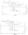
Fig. 1 represents an example of anti-bubble generator according to the invention. -
Fig. 2 represents another example of anti-bubble generator according to the invention. -
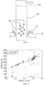
Fig. 3 represents a gas/liquid exchange column comprising of anti-bubble generators according to the invention. -
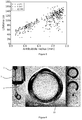
Figure 4 shows anti-bubbles lifetime as a function of anti-bubbles diameters. -
Figure 5 shows anti-bubbles lifetime as a function of surfactant concentration. -
Figure 6 shows different anti-bubbles stage, from birth to death. -
Figure 7 shows an example of micro-fluidic setup of the anti-bubble generator of the invention, during injection of a liquid jet. -
Figure 8 shows an example of micro-fluidic setup of the anti-bubble generator of the invention before the injection of a liquid jet. -
- 1.
- Bell
- 2.
- Liquid injection tube
- 3.
- Gas injection tube
- 4.
- Injected liquid (second liquid)
- 5.
- Nozzle
- 6.
- Injected gas
- 7.
- Liquid jet
- 8.
- Gas/liquid interface
- 9.
- Anti-bubble membrane
- 10.
- Anti-bubble
- 11.
- First liquid
- 12.
- Entrapped gas
- 13.
- Liquid column
- 14.
- Exhaust gas pipe
- 15.
- Droplets
- 16.
- Gas capillary
- 17.
- Gas gap between the gas capillary and the inner capillary
- 18.
- Inner liquid capillary
- 19.
- Microfluidic conduit
- 20.
- Microfluidic anti-bubble generator
- 21.
- Air cavity
- In the anti-bubble generator of the invention, the anti-bubbles 10 are generated in a confined environment which permits to have a better control of both the liquid/
gas interface 8, and thegas 12 composition. This confinement is obtained by the use of asmall bell 1 immersed in afirst liquid 11, thebell 1 being oriented downwards, thereby entrapping thegas 12. - The anti-bubbles 10 in the anti-bubble generator of the invention are generated by injecting a
second liquid 4 through atube 2 emerging in the entrappedgas 12, above the first liquid/gas interface 8, in the upper region of thebell 1. Thetube 2 end comprises anozzle 5 that can be a simple orifice, or comprises means for generating individual droplets from a continuous flow in the tube. The liquid injection can be performed byintermittent jet 7, preferably of predetermined speed and volume, or by nebulization ofdroplets 15 through a spraying nozzle or a vibrating nozzle. - The
second liquid 4 is therefore forming the liquid phase entrapped in the gas membrane 9, the anti-bubble 10 being immersed in thesecond liquid 11. - The anti-bubble generator of the invention is scalable and can produce anti-bubble 10 of the size of a few tenths of micrometers to a few centimetres.
- In order to control the size of the anti-bubbles 10, the key parameters are mainly the speed of the jet, the diameter of the
nozzle 5, the position of thenozzle 5 relative to the liquid/gas interface 8 (distance and/or orientation), and, in the case ofintermittent jet 7, the volume ofindividual jets 7, or the volume of thedroplets 15 in the case of droplets injection. - In use, the distance between the liquid surface and the
nozzle 5 is selected so that individual droplets reaches the liquid/gas interface, and the nozzle diameter is selected, along with the jet speed and volume, to determine the droplets volume. Therefore, the distance of thenozzle 5 to the open surface of the bell is preferably comprised between 1 and 100 mm, and thenozzle 5 inner diameter is comprised between 0.01 and 10mm. - When using continuous jet, the speed of the liquid, nozzle diameter and the distance between the nozzle and the liquid is selected so that, due to the Rayleigh-Plateau instability, the jet forms isolated
droplets 15 before reaching the liquid/gas interface 8. - By "opened surface of the bell", it is meant in the present invention the surface coinciding, in use, with the liquid/gas interface, when the bell is completely filled up with gas.
- The distance between the opened surface of the bell and the
nozzle 5 of the injection tube is preferably adjustable. - In the present invention, the interstitial gas (forming the membrane) can advantageously be chosen. It can be a pure gas or a mixture, whose composition can be varied in time.
- In order to have a control of the gas enclosed in the anti-bubble membrane, the anti-bubble generator of the invention comprises means for injecting a gas of controlled composition and pressure in the bell. Preferably, the injection means comprises a
gas injection tube 3 emerging in the upper region of thebell 1. Advantageously, thegas injection tube 3 is connected to a pressurised source of gas, through a pressure gas regulator. - Preferably, the gas volume inside the
bell 1 is regulated by using a level sensor, injecting gas when the level of the liquid/gas interface 8 relative to thebell 1 reaches a predetermined value. - When using air for the membrane forming the anti-bubble, the pressurised source of gas can be a compressor, advantageously combined with filtering means, for filtering dust and other contaminant such as oil.
- Alternatively, the source of compressed gas may comprise a cylinder of compressed gas of known composition.
- Advantageously, the gas source may also be an exhaust gas to be filtred/cleaned by contact with the first and second liquid.
- Preferably, when using the anti-bubble generator of the invention, the
bell 1 is flushed with thegas 6 before the first use, after immersion of the bell in thefirst liquid 11. Advantageously, this flushing is performed by first filling the bell with the first liquid (when possible, by immersing it with its opening upwards), and then filling thebell 1 with thegas 6 of known composition. Thereby, a fresh liquid/gas interface 8 is generated, avoiding contamination from an opened environment. - An advantage of the invention is that the anti-bubble 10 can be generated at any depth. This can bring several advantages. For example, the buoyancy of the gas membrane tends to move the anti-bubble upwards, so, generating the anti-bubble at higher depth may increase their survival rate (lifetime). This can be, for example, used for improving gas dissolution or cleaning in a liquid (for example CO2 in carbonated soft drinks, oxygen in biological reactor,...). For example, a gas/liquid exchanger using the anti-bubble generator of the invention may comprise a high liquid column, comprising at his basis one or several anti-bubble generator of the invention. Such a reactor is represented in
fig. 3 . In that exchanger, there can be a plurality of complete anti-bubble generator according to the invention, or one or more bell(s) comprising a plurality of injection tubes. For example, the bell may take the form of an annular structure having the same cross-section as represented infigure 3 . - Such exchange columns are already known for "normal" bubble (i.e. gas bubbles in a liquid). Those exchange columns are used for example for the cleaning/trapping of combustion gas. Anti-bubbles going up slower than bubbles allow to decrease the height of the absorption column. Thus allowing to build smaller absorption column for the same efficiency.
- The invention may also be implemented in microfluidic application. A device suitable for such application is for example represented in
fig. 7 and 8 . In that figure, aninner capillary 18 is enclosed in an intermediate capillary 16 (or gas capillary). And theintermediate capillary 16 is enclosed in amicrofluidic conduit 19. Upon use, themicrofluidic conduit 19 is filled up with the first liquid, and theintermediate capillary 16 is filled up with a suitable gas. Preferably, theinner capillary 18 end is located inside theintermediate capillary 16 at a predetermined distance of theintermediate capillary 16 end, thereby defining agas cavity 21 through which the secondliquid jet 7 is injected upon use. Preferably, said predetermined distance is comprised between 1 to 4 times the outside diameters of theinner capillary 16. Preferably, the inner surface of theintermediate capillary 16 is a hydrophobic surface, the second liquid presenting a high contact angle on said hydrophobic surface (preferably higher that 90°). - In the case of microfluidic application, the bell wall is therefore formed by the
intermediate capillary 16, the gas injection tube being co-axially connected to the bell. - The anti-bubble generator may also advantageously be used for surface rheometry, for measuring critical thickness of film breaking, in microfluidic process, in antifoam systems, for improving contrasts in ultrasonic imagery, or for mixing liquids (i.e. the second liquid being efficiently dispersed in the first liquid by the process of the invention). It can also be used as foam generator in protein skimmer wherein the specific surface of the foam is improved, thereby increasing the ratio between the extracted surfactant (protein) and the interstitial liquid remaining in the foam.
- In order to avoid the trapping of the anti-bubbles in the anti-bubble generator when they move upward, the jet angle is advantageously slightly shifted from the vertical. Preferably, the bell axis is also shifted by a small angle from the vertical for the same reason. Alternatively, the anti-bubble may be moved away from the anti-bubble generator by a liquid flow. Or, the buoyancy of the anti-bubble gas membrane can be compensated by increasing the density of the second liquid.
- The first and second liquid can be different or not, but preferably, at least one of them comprises a surfactant or a surfactant mixture, to stabilise the gas/liquid interfaces of the gas membrane around the anti-bubble. Preferably, the surfactant comprises a non-ionic surfactant. It advantageously comprises a surfactant of developed chemical formula CxH2x+1-C6H4-(OC2H4)-OH, where x is comprised between 6 and 12. The surfactant comprises (or consist of) preferably Triton X-100 and/or Triton C12E6.
- The surfactant may also advantageously be based on biologically sourced surfactants such as proteins. Examples of liquids comprising natural protein surfactant are beer, microbiological reactor (for example for activated sludge treatment, or for production of specific molecules in the pharmaceutical industry), seawater (for example in protein skimmer).
- Advantageously, the surfactant concentration is above the critical micellar concentration (CMC), preferably, at least 3 times above the CMC, more preferably between 5 and 10 times the CMC. These concentrations are above the CMC in order to reduce the adsorption time at the interface of the surfactant.
- Due the confined environment of the liquid/gas interface, the anti-bubbles of the invention comprises less contaminant, such as dust, thereby reducing premature collapsing of the anti-bubble, and improving their lifetime.
- In the present example, a cylindrical bell having an inner diameter of 10 mm and a length of about 30 mm was used. The position of the nozzle was about 10 mm from the open surface, with the possibility of slightly moving the nozzle to optimize anti-bubble generation. The inner diameter of the nozzle was about 1.6 mm.
- The liquid jet's formation was produced by a pressure controller and an electric valve. While the controlled pressure adjusts the velocity of the liquid jet, the electric valve allows a fine tuning of the jet duration. Both of these conditions can be adjusted in order to produce anti-bubbles of a desired size.
- Equipment are cleaned three times with ethanol and rinsed three times with ultra-pure water. The first liquid (bulk) and the inner core (second liquid) of the anti-bubble is a mixture of ultra-pure water and Triton X100(TX100, Sigma-Aldrich, purity of 99%) at different concentrations.
- The liquids are saturated in gas (here air) in order to avoid the dissolution of the gas shell into the liquid. In order to maintain anti-bubbles away from the gas surfaces (both in the bell and the free surface above the first liquid), they are weighed down by adding glycerol to the core mixture (second liquid). Glycerol is flowed at the bottom of the tank so that a gradient density exists in order to avoid the anti-bubble to touch the bottom of the tank and explode from external perturbation.
-
Figure 4 shows the anti-bubble lifetime versus anti-bubble diameter for a concentration of triton X100 of 5CMC. In this figure, there are two kinds of anti-bubbles. - The lower group represents anti-bubbles that mostly die by touching an other anti-bubble while sinking. The middle group represents anti-bubbles that are closed to another smaller anti-bubble: when the smaller one bursts, the bigger one also explodes. There are also very few anti-bubbles that exploded in the 2 lower groups without any visible explanation. This last situation is much less frequent than it is with prior art anti-bubble generator.
-
Figure 5 shows the lifetime of anti-bubbles as a function of Triton X100 concentration, from 3 to 10 times CMC. Explained premature death has been rejected from results in this figure. - A clear influence of the radius on the maximum lifetime of an anti-bubble can be seen in this figure.
Claims (15)
- Anti-bubble generator comprising:∘ a bell (1);∘ an injection tube (2) emerging in the bell (1) for injecting liquid jets or droplets.
- The anti-bubble generator of claim 1 wherein the volume (12) enclosed in the bell is less than 1l.
- The anti-bubble generator of any of the previous claims wherein the injection tube end is located at a distance of the opened surface of the bell comprised between 10µm and 10mm.
- The anti-bubble generator of any of the previous claims wherein the injection tube may slide relative to the bell to determine the distance between the opened surface of the bell and the injection tube end (5).
- The anti-bubble generator of any of the previous claims wherein the inner diameter of the injection tube (2) is comprised between 0.01 and 10mm.
- The anti-bubble generator of any of the previous claims wherein the generator comprises means (6) for injecting a gas of predetermined composition and pressure in the bell (1).
- The anti-bubble generator of any of the previous claims comprising means for injecting intermittent liquid jet of predetermined volume and speed.
- System for generating anti-bubbles comprising a plurality of anti-bubble generators according to any of the previous claims.
- Method for generating anti-bubbles comprising the steps of:∘ providing a first liquid (11);∘ providing a gas/liquid interface at a depth below the liquid surface;∘ injecting droplets (15) or liquid jets (7) of a second liquid (4) into the first liquid (11) through the liquid/gas interface, thereby producing anti-bubbles (10).
- The method of claim 9 comprising the step of providing at least one anti-bubble generator according to any of claim 1 to 8, wherein the gas liquid interface is provided by immerging the opened surface of the bell (1) of the at least one anti-bubble generator, the opening of the bell (1) being oriented downwards, thereby creating a liquid/gas interface (8) at said opened surface of the bell (1);
- The method of claim 9 or 10 wherein the droplets speed or liquid jets is comprised between 5 and 60cm/s.
- The method of any of claim 9 to 11 wherein the second liquid is different from first liquid.
- The method of any of claim 9 to 12 wherein the first and/or second liquid comprises a surfactant.
- The method of claim 13 wherein the surfactant is a non-ionic surfactant.
- The method of claim 13 wherein the surfactant is selected from the group consisting of Triton surfactant and protein surfactant.
Priority Applications (1)
| Application Number | Priority Date | Filing Date | Title |
|---|---|---|---|
| EP16153781.6A EP3202491A1 (en) | 2016-02-02 | 2016-02-02 | Anti-bubble generator |
Applications Claiming Priority (1)
| Application Number | Priority Date | Filing Date | Title |
|---|---|---|---|
| EP16153781.6A EP3202491A1 (en) | 2016-02-02 | 2016-02-02 | Anti-bubble generator |
Publications (1)
| Publication Number | Publication Date |
|---|---|
| EP3202491A1 true EP3202491A1 (en) | 2017-08-09 |
Family
ID=55484808
Family Applications (1)
| Application Number | Title | Priority Date | Filing Date |
|---|---|---|---|
| EP16153781.6A Withdrawn EP3202491A1 (en) | 2016-02-02 | 2016-02-02 | Anti-bubble generator |
Country Status (1)
| Country | Link |
|---|---|
| EP (1) | EP3202491A1 (en) |
Cited By (4)
| Publication number | Priority date | Publication date | Assignee | Title |
|---|---|---|---|---|
| CN109589649A (en) * | 2018-11-20 | 2019-04-09 | 浙江大学 | A kind of anti-bubble transport device and method |
| CN109663517A (en) * | 2018-11-20 | 2019-04-23 | 浙江大学 | A kind of stable time-controlling arrangement of anti-bubble |
| CN110304193A (en) * | 2019-07-11 | 2019-10-08 | 上海海事大学 | Anti-bubble drag reduction method and system for ships |
| CN112275150A (en) * | 2020-10-16 | 2021-01-29 | 上海海事大学 | A method for preparing anti-bubble by using pneumatic pulse device |
Citations (3)
| Publication number | Priority date | Publication date | Assignee | Title |
|---|---|---|---|---|
| US1907455A (en) * | 1929-12-28 | 1933-05-09 | Petroleum Rectifying Co California | Method of contacting fluids |
| WO1999030812A1 (en) * | 1997-12-17 | 1999-06-24 | Universidad De Sevilla | Device and method for aeration of fluids |
| WO2012162296A2 (en) * | 2011-05-23 | 2012-11-29 | President And Fellows Of Harvard College | Control of emulsions, including multiple emulsions |
-
2016
- 2016-02-02 EP EP16153781.6A patent/EP3202491A1/en not_active Withdrawn
Patent Citations (3)
| Publication number | Priority date | Publication date | Assignee | Title |
|---|---|---|---|---|
| US1907455A (en) * | 1929-12-28 | 1933-05-09 | Petroleum Rectifying Co California | Method of contacting fluids |
| WO1999030812A1 (en) * | 1997-12-17 | 1999-06-24 | Universidad De Sevilla | Device and method for aeration of fluids |
| WO2012162296A2 (en) * | 2011-05-23 | 2012-11-29 | President And Fellows Of Harvard College | Control of emulsions, including multiple emulsions |
Non-Patent Citations (1)
| Title |
|---|
| MU MAST: "Antibubble generator (ULB)", 2 December 2014 (2014-12-02), pages 1, XP054976651, Retrieved from the Internet <URL:https://www.youtube.com/watch?v=l49BoJCcf_I> [retrieved on 20160707] * |
Cited By (5)
| Publication number | Priority date | Publication date | Assignee | Title |
|---|---|---|---|---|
| CN109589649A (en) * | 2018-11-20 | 2019-04-09 | 浙江大学 | A kind of anti-bubble transport device and method |
| CN109663517A (en) * | 2018-11-20 | 2019-04-23 | 浙江大学 | A kind of stable time-controlling arrangement of anti-bubble |
| CN109663517B (en) * | 2018-11-20 | 2020-08-18 | 浙江大学 | Anti-bubble stabilization time control device |
| CN110304193A (en) * | 2019-07-11 | 2019-10-08 | 上海海事大学 | Anti-bubble drag reduction method and system for ships |
| CN112275150A (en) * | 2020-10-16 | 2021-01-29 | 上海海事大学 | A method for preparing anti-bubble by using pneumatic pulse device |
Similar Documents
| Publication | Publication Date | Title |
|---|---|---|
| KR102453570B1 (en) | Ultra-fine bubble generation method, ultra-fine bubble-containing liquid manufacturing apparatus and manufacturing method, and ultra-fine bubble-containing liquid | |
| Xie et al. | Preparation and characterization of microbubbles with a porous ceramic membrane | |
| Makuta et al. | Generation of microbubbles from hollow cylindrical ultrasonic horn | |
| US8726918B2 (en) | Nanofluid generator and cleaning apparatus | |
| CN102781561B (en) | Bubble generating device and method | |
| CN104096491B (en) | Anti-bubble generator and preparation method | |
| JP2006088154A (en) | Method and apparatus for controlling transient cavitation | |
| US20160236160A1 (en) | Microbubble generating device and contaminated water purifying system provided with microbubble generating device | |
| JP2011101827A (en) | Saturated water generator, and apparatus for making saturated water or saturated liquid | |
| CN204365155U (en) | Anti-bubble generator | |
| US20200156018A1 (en) | Fine bubble generating method and fine bubble generating apparatus | |
| WO2017056323A1 (en) | Device for dissolving oxygen in water and method for dissolving oxygen in water using same | |
| Hu et al. | Experimental investigation on submerged gas-liquid mixture injection into water through a micro-channel | |
| JP2010158672A (en) | Bubble generation method, bubble generation apparatus, and ozone water producing method | |
| US10384218B2 (en) | Liquid atomization method and device | |
| JP2007117799A (en) | Microbubble generator and microbubble generating apparatus using the same | |
| CN104984701B (en) | A kind of cavitation cloud microvesicle preparation facilities and its method | |
| JP2009106918A (en) | Fine bubble generator | |
| CN206229216U (en) | A kind of device for realizing anti-bubbles burst | |
| CN110368824B (en) | Gas-liquid mixing device | |
| JP4133045B2 (en) | Gas dissolver and water treatment apparatus equipped with them | |
| CN205084732U (en) | Cavitation cloud microbubble preparation facilities | |
| WO2019043970A1 (en) | Device for dissolving oxygen in water and method for dissolving oxygen in water using same | |
| KR101637885B1 (en) | Apparatus for absorbing the ultra-fine bubble and controlling the bubble size using the bubble stormer, and that method | |
| JP4866295B2 (en) | Fine bubble sorting and collection device |
Legal Events
| Date | Code | Title | Description |
|---|---|---|---|
| PUAI | Public reference made under article 153(3) epc to a published international application that has entered the european phase |
Free format text: ORIGINAL CODE: 0009012 |
|
| AK | Designated contracting states |
Kind code of ref document: A1 Designated state(s): AL AT BE BG CH CY CZ DE DK EE ES FI FR GB GR HR HU IE IS IT LI LT LU LV MC MK MT NL NO PL PT RO RS SE SI SK SM TR |
|
| AX | Request for extension of the european patent |
Extension state: BA ME |
|
| STAA | Information on the status of an ep patent application or granted ep patent |
Free format text: STATUS: THE APPLICATION IS DEEMED TO BE WITHDRAWN |
|
| 18D | Application deemed to be withdrawn |
Effective date: 20180210 |