EP3202367A1 - Dental prosthesis manufacture method - Google Patents
Dental prosthesis manufacture method Download PDFInfo
- Publication number
- EP3202367A1 EP3202367A1 EP15846160.8A EP15846160A EP3202367A1 EP 3202367 A1 EP3202367 A1 EP 3202367A1 EP 15846160 A EP15846160 A EP 15846160A EP 3202367 A1 EP3202367 A1 EP 3202367A1
- Authority
- EP
- European Patent Office
- Prior art keywords
- dental
- opening
- resin body
- resin
- reinforcement
- Prior art date
- Legal status (The legal status is an assumption and is not a legal conclusion. Google has not performed a legal analysis and makes no representation as to the accuracy of the status listed.)
- Granted
Links
Images




Classifications
-
- A—HUMAN NECESSITIES
- A61—MEDICAL OR VETERINARY SCIENCE; HYGIENE
- A61C—DENTISTRY; APPARATUS OR METHODS FOR ORAL OR DENTAL HYGIENE
- A61C13/00—Dental prostheses; Making same
- A61C13/0003—Making bridge-work, inlays, implants or the like
- A61C13/0004—Computer-assisted sizing or machining of dental prostheses
-
- A—HUMAN NECESSITIES
- A61—MEDICAL OR VETERINARY SCIENCE; HYGIENE
- A61C—DENTISTRY; APPARATUS OR METHODS FOR ORAL OR DENTAL HYGIENE
- A61C13/00—Dental prostheses; Making same
- A61C13/0003—Making bridge-work, inlays, implants or the like
- A61C13/0006—Production methods
-
- A—HUMAN NECESSITIES
- A61—MEDICAL OR VETERINARY SCIENCE; HYGIENE
- A61C—DENTISTRY; APPARATUS OR METHODS FOR ORAL OR DENTAL HYGIENE
- A61C13/00—Dental prostheses; Making same
- A61C13/08—Artificial teeth; Making same
- A61C13/087—Artificial resin teeth
-
- A—HUMAN NECESSITIES
- A61—MEDICAL OR VETERINARY SCIENCE; HYGIENE
- A61C—DENTISTRY; APPARATUS OR METHODS FOR ORAL OR DENTAL HYGIENE
- A61C5/00—Filling or capping teeth
- A61C5/70—Tooth crowns; Making thereof
- A61C5/77—Methods or devices for making crowns
-
- A—HUMAN NECESSITIES
- A61—MEDICAL OR VETERINARY SCIENCE; HYGIENE
- A61C—DENTISTRY; APPARATUS OR METHODS FOR ORAL OR DENTAL HYGIENE
- A61C9/00—Impression cups, i.e. impression trays; Impression methods
- A61C9/004—Means or methods for taking digitized impressions
- A61C9/0046—Data acquisition means or methods
-
- A—HUMAN NECESSITIES
- A61—MEDICAL OR VETERINARY SCIENCE; HYGIENE
- A61C—DENTISTRY; APPARATUS OR METHODS FOR ORAL OR DENTAL HYGIENE
- A61C8/00—Means to be fixed to the jaw-bone for consolidating natural teeth or for fixing dental prostheses thereon; Dental implants; Implanting tools
- A61C8/0048—Connecting the upper structure to the implant, e.g. bridging bars
- A61C8/005—Connecting devices for joining an upper structure with an implant member, e.g. spacers
-
- A—HUMAN NECESSITIES
- A61—MEDICAL OR VETERINARY SCIENCE; HYGIENE
- A61C—DENTISTRY; APPARATUS OR METHODS FOR ORAL OR DENTAL HYGIENE
- A61C8/00—Means to be fixed to the jaw-bone for consolidating natural teeth or for fixing dental prostheses thereon; Dental implants; Implanting tools
- A61C8/0048—Connecting the upper structure to the implant, e.g. bridging bars
- A61C8/005—Connecting devices for joining an upper structure with an implant member, e.g. spacers
- A61C8/0051—Abutment monobloc with restoration
-
- A—HUMAN NECESSITIES
- A61—MEDICAL OR VETERINARY SCIENCE; HYGIENE
- A61C—DENTISTRY; APPARATUS OR METHODS FOR ORAL OR DENTAL HYGIENE
- A61C9/00—Impression cups, i.e. impression trays; Impression methods
- A61C9/004—Means or methods for taking digitized impressions
- A61C9/0046—Data acquisition means or methods
- A61C9/0053—Optical means or methods, e.g. scanning the teeth by a laser or light beam
Definitions
- This invention relates to a method for manufacturing a dental prosthesis, and more particularly relates to a method for manufacturing a dental prosthesis made of resin where a dental reinforcement is arranged.
- a bridge is a dental prosthesis that is used when a part of teeth is lost and its root does not exist.
- This is a dental prosthesis that holds an artificial tooth in an space produced by a lost tooth, using a natural tooth (remaining tooth) remaining in one side of the space as a basis (abutment tooth) (or using natural teeth remaining in both sides of the space).
- a bridge is made as follows: prior to making a bridge, an abutment tooth is ground, to have a shape easy for a dental prosthesis to be attached to (for example, a frustoconical shape); an impression of a portion including a space produced by a lost tooth and the abutment tooth of the above described shape is taken, to obtain a counterdie of a shape of a portion for which a bridge is made; further, a plaster cast is made according to this impression, the shape is determined based on the plaster cast, to make the bridge out of resin.
- dentures where artificial teeth are arranged on denture bases that cover alveolar ridges are provided. Resin is also used for these denture bases.
- Patent Literature 2 describes formation of a bridge with a fiber-reinforced composite material for dental restorations ([0009] of Patent Literature 2).
- a cavity to face a treatment site (a portion where a tooth is lost) is formed in each adjacent tooth that is positioned in either side of the treatment site where a tooth is lost;
- the glass reinforced composite material is cut longer than a distance between the cavities in both adjacent teeth, and is immersed in resin or the like to put resin-coating thereon; after that, both ends thereof are placed in the cavities in both adjacent teeth as the center part thereof is bent toward a gum; resin material is poured into both cavities, to be polymerized and cured along with the fiber-reinforced composite material for dental restorations to be fixed; after that, resin material is built up in the shape of a tooth on this fixed glass reinforced composite material and cured, to make a bridge.
- the fiber-reinforced composite material for dental restorations is arranged so as to be laid across occlusal surfaces of crowns (crown-shaped artificial teeth attached to abutment teeth) and an occlusal surface of a false tooth (an artificial tooth held by a lost tooth portion) with preference to Fig. 2 , which is problematic in aesthetics etc.
- occlusal surfaces are ground, to arrange the fiber-reinforced composite material for dental restorations, and after that, resin material is built up. Occlusal surfaces are formed by this build-up, and are not exact surfaces obtained by an impression.
- An object of the present invention is to provide a method for manufacturing a dental prosthesis capable of properly arranging a dental reinforcement when a dental prosthesis made of resin where the dental reinforcement is arranged is manufactured.
- the present invention is a method for manufacturing a dental prosthesis where a dental reinforcement is arranged inside resin, the method comprising: turning information on an intraoral shape into data; designing, in a form of data, a shape of a resin body that is a part formed of resin based on the data obtained by said turning information; designing, in the form of data, a position of a dental reinforcement that is to be arranged inside the resin body; and forming, in the form of data, a space and an opening that communicates with an outside in the position in the resin body where the dental reinforcement is to be arranged, based on the position, to design a resin body with an opening.
- strength may be calculated after said designing a position of a dental reinforcement
- This invention may further include: after said forming a space and an opening, to design a resin body with an opening, making the resin body with an opening; inserting the dental reinforcement into the resin body with an opening; and covering the opening of the resin body with an opening.
- a dental reinforcement can be arranged at a proper position on a dental prosthesis made of resin in view of aesthetics, comfort and strength.
- a bridge 10 which is an example of a dental prosthesis manufactured according to the manufacturing method of the present invention will be described.
- Fig. 1 is an external perspective view of the bridge 10
- Fig. 2 is a cross-sectional view of the bridge 10 which is taken along the line II-II in Fig. 1 . That is, Fig. 2 is a cross-sectional view in a direction of aligning crowns 11 and a false tooth 12.
- FIGs. 1 and 2 two crowns 11 and the false tooth 12 arranged between the crowns 11 integrate, to form the bridge 10.
- a dental reinforcement 13 is arranged so as to be laid across the inside of these crowns 11 and the false tooth 12.
- Each crown 11 is a part formed of resin, and is arranged so as to cover an abutment tooth in the bridge 10 as publicly known, whereby the false tooth 12 is held in a lost tooth portion. Therefore, a recess 11 a is formed in each crown 11 in a side of the abutment tooth so as to open in the side of the abutment tooth. The abutment tooth is inserted into the recess 11 a. In the opposite side of the recess 11 a, an occlusal surface 11 b that copies an occlusal surface of a natural tooth is formed, to reproduce functions of a natural tooth.
- Publicly known embodiments can be employed as the crowns 11 as described above.
- the false tooth 12 is a part formed of resin, and is arranged at the lost tooth portion in an oral cavity by being held by the crowns 11.
- the false tooth 12 has an alveolar ridge opposite surface 12a that is arranged in a side of an alveolar ridge, and an occlusal surface 12b that is in the opposite side of the alveolar ridge opposite surface 12a.
- the alveolar ridge opposite surface 12a is a curved surface similar to a spherical face in this embodiment in order to prevent the alveolar ridge from being hurt.
- the occlusal surface 12b copies an occlusal surface of a natural tooth, to reproduce functions of a natural tooth.
- the dental reinforcement 13 is a board-like reinforcement member arranged inside the crowns 11 and the false tooth 12, as extending in the direction of arranging the crowns 11 and the false tooth 12. While publicly known one can be employed as the dental reinforcement 13, the dental reinforcement 13 is formed of material that can reinforce resin, such as glass fibers and a metallic plate.
- the arrangement of the dental reinforcement 13 is determined in the method for manufacturing a dental prosthesis described below.
- the dental reinforcement 13 is arranged closer to the recesses 11 a of the crowns 11 and the alveolar ridge opposite surface 12 of the false tooth 12, which are in the opposite side of the occlusal surfaces 11b and 12b.
- the occlusal surfaces 11b of the crowns 11 can be reproduced without changing occlusal surfaces obtained by impression taking, which makes it possible to obtain proper occlusion.
- the bridge 10 deforms in such a way that the false tooth 12 is pushed toward the alveolar ridge side upon occlusion.
- the dental reinforcement 13 be arranged in the side of the alveolar ridge opposite surface 12a also in view of reinforcement. in view of reinforcement.
- manufacturing method S1 the method for manufacturing a dental prosthesis S1 (hereinafter may be referred to as "manufacturing method S1") according to one embodiment will be described.
- manufacturing method S1 can be employed for manufacturing other types of dental prostheses.
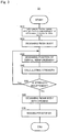
- Fig. 3 is a flowchart showing the flow of the manufacturing method S1.
- the manufacturing method S1 includes a step of digitizing an intraoral shape S10, a step of designing a resin body S20, a step of designing a position of a dental reinforcement S30, a step of calculating strength S40, a step of determining strength S50, a step of designing a resin body with an opening S60, and a step of making a prosthesis S70.
- abutment teeth Prior to the step of digitizing an intraoral shape S10, abutment teeth shall be ground by a publicly known method, and if needed (if digitized data is obtained from an impression), an impression based on this state shall be taken.
- information on an intraoral shape is turned into data.
- a means of turning the information into data include measuring the taken impression, measuring a model made from the impression, and directly measuring the inside of an oral cavity.
- Data of the shape obtained through such measurement is turned into CAD data.
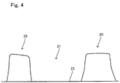
- a method of obtaining CAD data can be carried out with a publicly known device. For example, a three-dimensional optical scanner can be used. Whereby, for example as shown in Fig. 4 , such information is turned into data as forms of and positional relationship between two abutment teeth 20, a lost tooth portion 21 that in a space formed between the abutment teeth 20, and an alveolar ridge 22, which enables the information to be calculated.
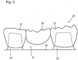
- a shape of a resin body 30 is determined in the form of data as shown in Fig. 5 based on the data obtained in the step of digitizing an intraoral shape S10.
- the resin body 30 has a form including crowns 31 and false tooth 32 except a dental reinforcement. At this time, a position of a dental reinforcement is not determined yet. While non-limiting methods of determining a shape of the resin body 30 in this step are used, such a method can be employed that selection is made based on shapes obtained through a database where a plurality of typical forms are stored, and the selected shape is combined with the shape of an occlusal surface that had been obtained in advance before the abutment teeth 20 were ground.
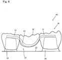
- the step of designing a position of a dental reinforcement S30 is a step of determining a position of a dental reinforcement in the resin body 30 obtained in the step of designing a resin body S20, in the form of data.
- a bridge 40 that is the resin body 30 where a dental reinforcement 33 is arranged is obtained in the form of data.
- a position of the dental reinforcement is determined to be arranged so as to reinforce a portion where a crack or the like forms upon applying occlusal pressure. At this time, it is important to take the thickness of the resin body 30 around the dental reinforcement 33 and the material of resin into consideration.
- the step of calculating strength S40 is a step of calculating strength of the bridge 40 obtained in the step of designing a position of a dental reinforcement S30. Whereby, the strength can be confirmed, and the effect of the reinforcement can be further surely confirmed.
- Publicly known simulation software can be used for the strength calculation.
- the strength is evaluated in the step of determining strength S50. If the strength is insufficient, the process returns to the step of designing a position of a dental reinforcement S30, and the form and the position of the dental reinforcement are changed. If there is no problem in the strength, the process goes on to the following step.
- step of calculating strength S40 is not necessarily carried out on a dental prosthesis all the time. If the step S40 is not carried out, the process can go on to the step of designing a resin body with an opening S60, skipping the step of calculating strength S40 and the step of determining strength S50.
- the step of designing a resin body with an opening S60 is a step of designing a resin body with an opening 35 that has a space and an opening for embedding the dental reinforcement 13 when the bridge 10 is manufactured.
- Fig. 7 shows this.
- a dental reinforcement arrangement space 36 that has an opening 36a is formed in the resin body 30 obtained in the step of designing a resin body S20, in the form of data in order that the dental reinforcement can be inserted into the position determined in the step of designing a position of a dental reinforcement S30, to be the resin body with an opening 35.
- the dental reinforcement can be properly arranged.
- Some methods are considered as means for filling this opening 36a in the end. Examples include: a method of filling the space 36 with resin before curing, and then curing the resin; a method of closing a lid made of resin to cover the opening 36a (at this time, a member to be the lid is separately made in the form of data as well); and a method of forming a plurality of parts into the resin body 30, one of which is the resin body with an opening 35, and combining the one with the other parts, to cover the opening 36a.
- the step of making a prosthesis S70 is a step of making the resin body with an opening 35 obtained in the form of data in the step of designing a resin body with an opening S60, with a tool device.
- Fig. 8 shows a flowchart of procedure of the step of making a prosthesis S70.
- the step of making a prosthesis S70 includes a step of making a resin body with an opening S71, a step of arranging a dental reinforcement S72 and a step of covering an opening S73.
- an actual resin body with an opening 15 is made based on the resin body with an opening 35 obtained in the form of data in the step of designing a resin body with an opening S60.
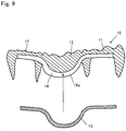
- a dental reinforcement arrangement space 16 corresponding to the dental reinforcement arrangement space 36, and an opening 16a corresponding to the opening 36a are formed (see Fig. 9 ).
- the resin body with an opening 15 can be made by cutting-out or the like with an NC machine tool.
- the step of arranging a dental reinforcement S72 is, as shown in Fig. 9 , a step of arranging the dental reinforcement 13 in the resin body with an opening 15 obtained in the step of making a resin body with an opening S71.
- the dental reinforcement 13 can be easily arranged because the dental reinforcement arrangement space 16 and the opening 16a for arranging the dental reinforcement 13 are provided with the resin body with an opening 15 in advance.
- the step of covering the opening S73 is a step of covering the opening with a proper method. Examples include: a method of filling the dental reinforcement arrangement space 16 with resin before curing, and then curing the resin; a method of closing a lid made of resin to cover the opening 16a (at this time, a member to be the lid is separately made as well); and a method of forming a plurality of parts, one of which is the resin body with an opening 15, and combining the one with the other parts, to cover the opening 16a.
- the bridge 10 can be obtained.
- the dental reinforcement 13 can be arranged anywhere except a portion where causes a problem about aesthetics or a portion necessary to be avoided.
- processing can be done on the data using CAD/CAM.
- the improvement of the strength can be more efficiently achieved by including the step of calculating strength S40.
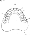
- Fig. 10 shows a dental prosthesis according to another example made with the manufacturing method S1.
- a dental prosthesis of this example is a denture 110.
- a dental reinforcement 113 is arranged inside a denture base 111.
- the denture 110 is composed of the denture base 111, the dental reinforcement 113 and a plurality of artificial teeth 121.
- the denture base 111 is a member that has functions of holding the artificial teeth 121 in predetermined positions, and stably attaching the denture itself onto an oral mucosa. As seen from FIG. 10 , the denture base 111 includes a ridge part 112 that rises like a ridge as a portion where the artificial teeth 121 are arranged, and the artificial teeth 121 are arranged along this ridge part 112.
- the dental reinforcement 113 is the same as the dental reinforcement 13 described above.
- the dental reinforcement 113 is arranged inside the denture base 111, closer to the side where the artificial teeth 121 are arranged. Whereby, it can be prevented that the dental reinforcement 113 hurts a surface of a use's mucosa.
- the dental reinforcement 113 has a shape like an arc along the direction where the artificial teeth 121 are arranged.
- the artificial teeth 121 are artificial teeth made so as to have the function of natural teeth that is lost, instead of the natural teeth.
- the artificial teeth 121 are arranged along the ridge part 112 of the denture base 111 like an arc, that is, like a row of teeth, and function as natural teeth.
Landscapes
- Health & Medical Sciences (AREA)
- Oral & Maxillofacial Surgery (AREA)
- Dentistry (AREA)
- Epidemiology (AREA)
- Life Sciences & Earth Sciences (AREA)
- Animal Behavior & Ethology (AREA)
- General Health & Medical Sciences (AREA)
- Public Health (AREA)
- Veterinary Medicine (AREA)
- Engineering & Computer Science (AREA)
- Manufacturing & Machinery (AREA)
- Dental Prosthetics (AREA)
Abstract
Description
- This invention relates to a method for manufacturing a dental prosthesis, and more particularly relates to a method for manufacturing a dental prosthesis made of resin where a dental reinforcement is arranged.
- For recent years, resin has been used for a dental prosthesis such as a bridge and a denture base for a false tooth according to development of dental resin material because resin has advantages of excellent aesthetics etc.
- For example, a bridge is a dental prosthesis that is used when a part of teeth is lost and its root does not exist. This is a dental prosthesis that holds an artificial tooth in an space produced by a lost tooth, using a natural tooth (remaining tooth) remaining in one side of the space as a basis (abutment tooth) (or using natural teeth remaining in both sides of the space).
- For example, a bridge is made as follows: prior to making a bridge, an abutment tooth is ground, to have a shape easy for a dental prosthesis to be attached to (for example, a frustoconical shape); an impression of a portion including a space produced by a lost tooth and the abutment tooth of the above described shape is taken, to obtain a counterdie of a shape of a portion for which a bridge is made; further, a plaster cast is made according to this impression, the shape is determined based on the plaster cast, to make the bridge out of resin.
- When all the teeth are lost, dentures where artificial teeth are arranged on denture bases that cover alveolar ridges are provided. Resin is also used for these denture bases.
- However, the mechanical strength of resin is lower than metal in tension and bending. Thus, a crack might form in some portion due to lack of the strength. For example, it is employed that lack of the strength is made up for by using a metallic frame together when a dental prosthesis is made using hard resin. However, this method takes a lot of effort.
- In contrast, as shown in
Fig. 1 ofPatent Literature 1, such a bridge is suggested that a fiber-reinforced composite material for dental restorations which comprises glass fibers in the shape of a bar is applied to. According to this, lack of the strength of a bridge made of resin can be made up for. - Patent Literature 2 describes formation of a bridge with a fiber-reinforced composite material for dental restorations ([0009] of Patent Literature 2). According to this, a cavity to face a treatment site (a portion where a tooth is lost) is formed in each adjacent tooth that is positioned in either side of the treatment site where a tooth is lost; the glass reinforced composite material is cut longer than a distance between the cavities in both adjacent teeth, and is immersed in resin or the like to put resin-coating thereon; after that, both ends thereof are placed in the cavities in both adjacent teeth as the center part thereof is bent toward a gum; resin material is poured into both cavities, to be polymerized and cured along with the fiber-reinforced composite material for dental restorations to be fixed; after that, resin material is built up in the shape of a tooth on this fixed glass reinforced composite material and cured, to make a bridge.
-
- Patent Literature 1:
JP H11-116422A - Patent Literature 2:
JP 2007-68821A - However, in the invention of
Patent Literature 1, concerning employment of the fiber-reinforced composite material for dental restorations to a bridge, the fiber-reinforced composite material for dental restorations is arranged so as to be laid across occlusal surfaces of crowns (crown-shaped artificial teeth attached to abutment teeth) and an occlusal surface of a false tooth (an artificial tooth held by a lost tooth portion) with preference toFig. 2 , which is problematic in aesthetics etc. - On the other hand, in the invention of Patent Literature 2, occlusal surfaces are ground, to arrange the fiber-reinforced composite material for dental restorations, and after that, resin material is built up. Occlusal surfaces are formed by this build-up, and are not exact surfaces obtained by an impression.
- It is difficult to properly arrange such a fiber-reinforced composite material for dental restorations (dental reinforcement) in a dental prosthesis in view of aesthetics, an effect of reinforcement, a shape of the dental prosthesis, and so on. For example, according to the above described
Patent Literatures 1 and 2, a problem might arise in aesthetics. If a dental reinforcement is arranged in a part other than a dental prosthesis in view of aesthetics, a thin portion of a resin part is formed by a groove and/or a hole for arranging the dental reinforcement, which sometimes causes the strength to lower conversely. - An object of the present invention is to provide a method for manufacturing a dental prosthesis capable of properly arranging a dental reinforcement when a dental prosthesis made of resin where the dental reinforcement is arranged is manufactured.
- The present invention will be described hereinafter.
- The present invention is a method for manufacturing a dental prosthesis where a dental reinforcement is arranged inside resin, the method comprising: turning information on an intraoral shape into data; designing, in a form of data, a shape of a resin body that is a part formed of resin based on the data obtained by said turning information; designing, in the form of data, a position of a dental reinforcement that is to be arranged inside the resin body; and forming, in the form of data, a space and an opening that communicates with an outside in the position in the resin body where the dental reinforcement is to be arranged, based on the position, to design a resin body with an opening.
- In this invention, strength may be calculated after said designing a position of a dental reinforcement
- This invention may further include: after said forming a space and an opening, to design a resin body with an opening, making the resin body with an opening; inserting the dental reinforcement into the resin body with an opening; and covering the opening of the resin body with an opening.
- According to the present invention, a dental reinforcement can be arranged at a proper position on a dental prosthesis made of resin in view of aesthetics, comfort and strength.
-
- Fig. 1
- is an external perspective view of a
bridge 10. - Fig. 2
- is a cross-sectional view of the
bridge 10. - Fig. 3
- is a flowchart of a method for manufacturing a dental prosthesis S1.
- Fig. 4
- shows a step of digitizing an intraoral shape S10.
- Fig. 5
- shows a step of designing a resin body S20.
- Fig.6
- shows a step of designing a position of a dental reinforcement S30.
- Fig. 7
- shows a step of designing a resin body with an opening S60.
- Fig. 8
- is a flowchart of a step of making a prosthesis S70.
- Fig. 9
- shows a step of arranging a dental reinforcement S72.
- Fig. 10
- is an external view of a
denture 110. - The present invention will be described hereinafter based on embodiments shown in the drawings. It is noted that this invention is not limited to these embodiments.
- First, a
bridge 10, which is an example of a dental prosthesis manufactured according to the manufacturing method of the present invention will be described.Fig. 1 is an external perspective view of thebridge 10, andFig. 2 is a cross-sectional view of thebridge 10 which is taken along the line II-II inFig. 1 . That is,Fig. 2 is a cross-sectional view in a direction of aligningcrowns 11 and afalse tooth 12. - As seen from
Figs. 1 and2 , twocrowns 11 and thefalse tooth 12 arranged between thecrowns 11 integrate, to form thebridge 10. Adental reinforcement 13 is arranged so as to be laid across the inside of thesecrowns 11 and thefalse tooth 12. - Each
crown 11 is a part formed of resin, and is arranged so as to cover an abutment tooth in thebridge 10 as publicly known, whereby thefalse tooth 12 is held in a lost tooth portion. Therefore, arecess 11 a is formed in eachcrown 11 in a side of the abutment tooth so as to open in the side of the abutment tooth. The abutment tooth is inserted into therecess 11 a. In the opposite side of therecess 11 a, anocclusal surface 11 b that copies an occlusal surface of a natural tooth is formed, to reproduce functions of a natural tooth. Publicly known embodiments can be employed as thecrowns 11 as described above. - The
false tooth 12 is a part formed of resin, and is arranged at the lost tooth portion in an oral cavity by being held by thecrowns 11. Thefalse tooth 12 has an alveolar ridge oppositesurface 12a that is arranged in a side of an alveolar ridge, and anocclusal surface 12b that is in the opposite side of the alveolar ridge oppositesurface 12a. While a publicly known embodiment can also be employed as thefalse tooth 12, the alveolar ridge oppositesurface 12a is a curved surface similar to a spherical face in this embodiment in order to prevent the alveolar ridge from being hurt. Theocclusal surface 12b copies an occlusal surface of a natural tooth, to reproduce functions of a natural tooth. - As seen from
Fig. 2 , thedental reinforcement 13 is a board-like reinforcement member arranged inside thecrowns 11 and thefalse tooth 12, as extending in the direction of arranging thecrowns 11 and thefalse tooth 12. While publicly known one can be employed as thedental reinforcement 13, thedental reinforcement 13 is formed of material that can reinforce resin, such as glass fibers and a metallic plate. - The arrangement of the
dental reinforcement 13 is determined in the method for manufacturing a dental prosthesis described below. In this embodiment, thedental reinforcement 13 is arranged closer to therecesses 11 a of thecrowns 11 and the alveolar ridge oppositesurface 12 of thefalse tooth 12, which are in the opposite side of theocclusal surfaces occlusal surfaces 11b of thecrowns 11 can be reproduced without changing occlusal surfaces obtained by impression taking, which makes it possible to obtain proper occlusion. - The
bridge 10 deforms in such a way that thefalse tooth 12 is pushed toward the alveolar ridge side upon occlusion. Thus, it is preferable that thedental reinforcement 13 be arranged in the side of the alveolar ridge oppositesurface 12a also in view of reinforcement. in view of reinforcement. - Next, the method for manufacturing a dental prosthesis S1 (hereinafter may be referred to as "manufacturing method S1") according to one embodiment will be described. Here, to manufacture the
bridge 10 will be described as an example for easy understanding. However, the manufacturing method S1 can be employed for manufacturing other types of dental prostheses. -
Fig. 3 is a flowchart showing the flow of the manufacturing method S1. As seen fromFig. 3 , the manufacturing method S1 includes a step of digitizing an intraoral shape S10, a step of designing a resin body S20, a step of designing a position of a dental reinforcement S30, a step of calculating strength S40, a step of determining strength S50, a step of designing a resin body with an opening S60, and a step of making a prosthesis S70. Hereinafter each step will be described. Prior to the step of digitizing an intraoral shape S10, abutment teeth shall be ground by a publicly known method, and if needed (if digitized data is obtained from an impression), an impression based on this state shall be taken. - In the step of digitizing an intraoral shape S10, information on an intraoral shape is turned into data. Examples of a means of turning the information into data include measuring the taken impression, measuring a model made from the impression, and directly measuring the inside of an oral cavity. Data of the shape obtained through such measurement is turned into CAD data. A method of obtaining CAD data can be carried out with a publicly known device. For example, a three-dimensional optical scanner can be used. Whereby, for example as shown in
Fig. 4 , such information is turned into data as forms of and positional relationship between twoabutment teeth 20, a losttooth portion 21 that in a space formed between theabutment teeth 20, and analveolar ridge 22, which enables the information to be calculated. - In the step of designing a resin body S20, a shape of a
resin body 30 is determined in the form of data as shown inFig. 5 based on the data obtained in the step of digitizing an intraoral shape S10. Theresin body 30 has aform including crowns 31 andfalse tooth 32 except a dental reinforcement. At this time, a position of a dental reinforcement is not determined yet. While non-limiting methods of determining a shape of theresin body 30 in this step are used, such a method can be employed that selection is made based on shapes obtained through a database where a plurality of typical forms are stored, and the selected shape is combined with the shape of an occlusal surface that had been obtained in advance before theabutment teeth 20 were ground. - The step of designing a position of a dental reinforcement S30 is a step of determining a position of a dental reinforcement in the
resin body 30 obtained in the step of designing a resin body S20, in the form of data. Whereby, as shown inFig. 6 , abridge 40 that is theresin body 30 where adental reinforcement 33 is arranged is obtained in the form of data. - A position of the dental reinforcement is determined to be arranged so as to reinforce a portion where a crack or the like forms upon applying occlusal pressure. At this time, it is important to take the thickness of the
resin body 30 around thedental reinforcement 33 and the material of resin into consideration. - The step of calculating strength S40 is a step of calculating strength of the
bridge 40 obtained in the step of designing a position of a dental reinforcement S30. Whereby, the strength can be confirmed, and the effect of the reinforcement can be further surely confirmed. Publicly known simulation software can be used for the strength calculation. - When the step of calculating strength S40 is carried out, the strength is evaluated in the step of determining strength S50. If the strength is insufficient, the process returns to the step of designing a position of a dental reinforcement S30, and the form and the position of the dental reinforcement are changed. If there is no problem in the strength, the process goes on to the following step.
- It is noted that the step of calculating strength S40 is not necessarily carried out on a dental prosthesis all the time. If the step S40 is not carried out, the process can go on to the step of designing a resin body with an opening S60, skipping the step of calculating strength S40 and the step of determining strength S50.
- The step of designing a resin body with an opening S60 is a step of designing a resin body with an
opening 35 that has a space and an opening for embedding thedental reinforcement 13 when thebridge 10 is manufactured.Fig. 7 shows this. As shown inFig. 7 , a dentalreinforcement arrangement space 36 that has anopening 36a is formed in theresin body 30 obtained in the step of designing a resin body S20, in the form of data in order that the dental reinforcement can be inserted into the position determined in the step of designing a position of a dental reinforcement S30, to be the resin body with anopening 35. Whereby, the dental reinforcement can be properly arranged. - Some methods are considered as means for filling this
opening 36a in the end. Examples include: a method of filling thespace 36 with resin before curing, and then curing the resin; a method of closing a lid made of resin to cover theopening 36a (at this time, a member to be the lid is separately made in the form of data as well); and a method of forming a plurality of parts into theresin body 30, one of which is the resin body with anopening 35, and combining the one with the other parts, to cover theopening 36a. - The step of making a prosthesis S70 is a step of making the resin body with an
opening 35 obtained in the form of data in the step of designing a resin body with an opening S60, with a tool device.Fig. 8 shows a flowchart of procedure of the step of making a prosthesis S70. As seen fromFig. 8 , the step of making a prosthesis S70 includes a step of making a resin body with an opening S71, a step of arranging a dental reinforcement S72 and a step of covering an opening S73. - In the step of making a resin body with an opening S71, an actual resin body with an
opening 15 is made based on the resin body with anopening 35 obtained in the form of data in the step of designing a resin body with an opening S60. Thus, in the resin body with anopening 15, a dentalreinforcement arrangement space 16 corresponding to the dentalreinforcement arrangement space 36, and anopening 16a corresponding to theopening 36a are formed (seeFig. 9 ). The resin body with anopening 15 can be made by cutting-out or the like with an NC machine tool. - The step of arranging a dental reinforcement S72 is, as shown in
Fig. 9 , a step of arranging thedental reinforcement 13 in the resin body with anopening 15 obtained in the step of making a resin body with an opening S71. In this invention, thedental reinforcement 13 can be easily arranged because the dentalreinforcement arrangement space 16 and theopening 16a for arranging thedental reinforcement 13 are provided with the resin body with anopening 15 in advance. - The step of covering the opening S73 is a step of covering the opening with a proper method. Examples include: a method of filling the dental
reinforcement arrangement space 16 with resin before curing, and then curing the resin; a method of closing a lid made of resin to cover theopening 16a (at this time, a member to be the lid is separately made as well); and a method of forming a plurality of parts, one of which is the resin body with anopening 15, and combining the one with the other parts, to cover theopening 16a. - According to the above described manufacturing method S1, the
bridge 10 can be obtained. According to themanufacturing method S 1, thedental reinforcement 13 can be arranged anywhere except a portion where causes a problem about aesthetics or a portion necessary to be avoided. At this time, for example, processing can be done on the data using CAD/CAM. Thus, it is possible to efficiently prevent the strength from erroneously lowering even if the shape is complicated. Further, the improvement of the strength can be more efficiently achieved by including the step of calculating strength S40. -
Fig. 10 shows a dental prosthesis according to another example made with the manufacturing method S1. A dental prosthesis of this example is adenture 110. Adental reinforcement 113 is arranged inside adenture base 111. - The
denture 110 is composed of thedenture base 111, thedental reinforcement 113 and a plurality ofartificial teeth 121. - The
denture base 111 is a member that has functions of holding theartificial teeth 121 in predetermined positions, and stably attaching the denture itself onto an oral mucosa. As seen fromFIG. 10 , thedenture base 111 includes aridge part 112 that rises like a ridge as a portion where theartificial teeth 121 are arranged, and theartificial teeth 121 are arranged along thisridge part 112. - The
dental reinforcement 113 is the same as thedental reinforcement 13 described above. In this example, thedental reinforcement 113 is arranged inside thedenture base 111, closer to the side where theartificial teeth 121 are arranged. Whereby, it can be prevented that thedental reinforcement 113 hurts a surface of a use's mucosa. In view of the improvement of strength, thedental reinforcement 113 has a shape like an arc along the direction where theartificial teeth 121 are arranged. - The
artificial teeth 121 are artificial teeth made so as to have the function of natural teeth that is lost, instead of the natural teeth. Theartificial teeth 121 are arranged along theridge part 112 of thedenture base 111 like an arc, that is, like a row of teeth, and function as natural teeth. -
- 10
- bridge (dental prosthesis)
- 11
- crown
- 12
- false tooth (artificial tooth)
- 11a
- recess
- 11b
- occlusal surface
- 12a
- alveolar ridge opposite
surface 12a - 12b
- occlusal surface
- 13
- dental reinforcement
- 20
- abutment tooth
- 21
- lost tooth portion
- 22
- alveolar ridge
- 30
- resin body
- 31
- crown
- 32
- false tooth
- 33
- dental reinforcement
- 35
- resin body with an opening
- 36
- space
- 36a
- opening
Claims (3)
- A method for manufacturing a dental prosthesis where a dental reinforcement is arranged inside resin, the method comprising:turning information on an intraoral shape into data;designing, in a form of data, a shape of a resin body that is a part formed of resin based on the data;designing, in the form of data, a position of a dental reinforcement that is to be arranged inside the resin body; andforming, in the form of data, a space and an opening that communicates with an outside in the position in the resin body where the dental reinforcement is to be arranged, based on the position, to design a resin body with an opening.
- The method according to claim 1, further comprising: calculating strength after said designing a position of a dental reinforcement.
- The method according to claim 1 or 2, further comprising:after said forming a space and an opening, to design a resin body with an opening,making the resin body with an opening;inserting the dental reinforcement into the resin body with an opening; andcovering the opening of the resin body with an opening.
Applications Claiming Priority (2)
| Application Number | Priority Date | Filing Date | Title |
|---|---|---|---|
| JP2014198111 | 2014-09-29 | ||
| PCT/JP2015/077062 WO2016052321A1 (en) | 2014-09-29 | 2015-09-25 | Dental prosthesis manufacture method |
Publications (3)
| Publication Number | Publication Date |
|---|---|
| EP3202367A1 true EP3202367A1 (en) | 2017-08-09 |
| EP3202367A4 EP3202367A4 (en) | 2018-05-23 |
| EP3202367B1 EP3202367B1 (en) | 2020-08-05 |
Family
ID=55630359
Family Applications (1)
| Application Number | Title | Priority Date | Filing Date |
|---|---|---|---|
| EP15846160.8A Active EP3202367B1 (en) | 2014-09-29 | 2015-09-25 | Dental prosthesis manufacture method |
Country Status (6)
| Country | Link |
|---|---|
| US (1) | US10603142B2 (en) |
| EP (1) | EP3202367B1 (en) |
| JP (1) | JP6267804B2 (en) |
| KR (1) | KR101893713B1 (en) |
| CN (1) | CN106714728B (en) |
| WO (1) | WO2016052321A1 (en) |
Families Citing this family (6)
| Publication number | Priority date | Publication date | Assignee | Title |
|---|---|---|---|---|
| KR102650950B1 (en) | 2017-09-29 | 2024-03-26 | 서울반도체 주식회사 | Light emitting device for display and display apparatus having the same |
| DE102017221002A1 (en) * | 2017-11-23 | 2019-05-23 | Sirona Dental Systems Gmbh | Process for the production of a dental prosthetic item and dental prosthesis |
| KR102070165B1 (en) * | 2018-08-24 | 2020-01-28 | 고려대학교 산학협력단 | Reinforced resin inlay and Method of manufacturing for the same |
| KR20200113383A (en) | 2019-03-25 | 2020-10-07 | 장만종 | Incinerator Apparatus Can be Transported |
| IT201900023226A1 (en) * | 2019-12-06 | 2021-06-06 | Moi Composites S R L | PROCESS TO MAKE A STRUCTURE FOR REINFORCEMENT FOR DENTAL PROSTHESES IN CONTINUOUS FIBER COMPOSITE MATERIALS |
| CN113995536B (en) | 2020-07-28 | 2025-11-18 | 株式会社松风 | Reinforced Implantable Denture with Base and its Fabrication Method |
Family Cites Families (21)
| Publication number | Priority date | Publication date | Assignee | Title |
|---|---|---|---|---|
| US3197866A (en) * | 1962-11-01 | 1965-08-03 | Joseph B Barron | Dental prosthetic appliance |
| DE3604125A1 (en) * | 1986-02-10 | 1987-09-10 | Implantec Gmbh & Co Kg | DENTURES |
| US6371763B1 (en) * | 1997-11-28 | 2002-04-16 | Robert J. Sicurelli, Jr. | Flexible post in a dental post and core system |
| US5788498A (en) * | 1995-12-19 | 1998-08-04 | Ivoclar Ag | Method for manufacturing dental crowns |
| EP0895774A3 (en) | 1997-08-06 | 2002-01-30 | JENERIC/PENTRON Incorporated | Radiopaque dental composites |
| US6200136B1 (en) * | 1998-08-07 | 2001-03-13 | Jeneric/Pentron Incorporated | Fiber-reinforced dental bridge and method of manufacture thereof |
| US6270348B1 (en) * | 1999-03-01 | 2001-08-07 | Richard Petersen | Chopped fiber reinforced dental material |
| WO2001015620A1 (en) * | 1999-09-02 | 2001-03-08 | Jeneric/Pentron Incorporated | Method for manufacturing dental restorations |
| WO2003007834A1 (en) * | 2001-07-13 | 2003-01-30 | Degudent Gmbh | Production of replacement teeth from a three-dimensionally determined and digitised positive model |
| JP2004285023A (en) * | 2003-03-25 | 2004-10-14 | Takahito Kanie | Resin-reinforcing material for denture base, and method for producing denture base by using the same |
| JP2008512152A (en) * | 2003-09-09 | 2008-04-24 | モリス,クリストファー | Ceramic reinforcement bar for direct dental bridge |
| JP2005350421A (en) * | 2004-06-14 | 2005-12-22 | 裕 ▲高▼橋 | Dental restoration material and dentures using the same |
| US7699610B2 (en) * | 2004-07-22 | 2010-04-20 | Bryan Childress | Flexible denture and method to make same |
| EP1629793A1 (en) * | 2004-08-25 | 2006-03-01 | Remedent NV | Dental appliances |
| DE102004052365B4 (en) * | 2004-10-28 | 2010-08-26 | BEGO Bremer Goldschlägerei Wilh. Herbst GmbH & Co. KG | Method for producing a rapid prototyping model, a green body, a ceramic component and a metallic component |
| JP2007068821A (en) | 2005-09-08 | 2007-03-22 | Gc Corp | Reinforcing material for dental bridge |
| BRPI0708173A2 (en) * | 2006-02-21 | 2011-05-17 | Nusmile Ltd | prefabricated dental crown |
| KR100928724B1 (en) * | 2007-07-26 | 2009-11-27 | 이세준 | Dental prosthesis |
| SE0702661L (en) * | 2007-11-26 | 2009-05-27 | Lindberg Implants Ab | A bridge construction and a method for making a bridge construction |
| JP2012036136A (en) * | 2010-08-09 | 2012-02-23 | Takeshi Kameda | Dental prosthesis with metal clay to be whitened by baking |
| DE102013211154B4 (en) * | 2013-06-14 | 2021-06-10 | Kulzer Gmbh | Method for making a denture |
-
2015
- 2015-09-25 US US15/512,871 patent/US10603142B2/en active Active
- 2015-09-25 JP JP2016551965A patent/JP6267804B2/en active Active
- 2015-09-25 EP EP15846160.8A patent/EP3202367B1/en active Active
- 2015-09-25 CN CN201580048486.9A patent/CN106714728B/en active Active
- 2015-09-25 KR KR1020177003752A patent/KR101893713B1/en active Active
- 2015-09-25 WO PCT/JP2015/077062 patent/WO2016052321A1/en not_active Ceased
Also Published As
| Publication number | Publication date |
|---|---|
| EP3202367A4 (en) | 2018-05-23 |
| JPWO2016052321A1 (en) | 2017-04-27 |
| US20170296311A1 (en) | 2017-10-19 |
| CN106714728B (en) | 2019-11-08 |
| CN106714728A (en) | 2017-05-24 |
| KR101893713B1 (en) | 2018-08-30 |
| KR20170031189A (en) | 2017-03-20 |
| JP6267804B2 (en) | 2018-01-24 |
| EP3202367B1 (en) | 2020-08-05 |
| WO2016052321A1 (en) | 2016-04-07 |
| US10603142B2 (en) | 2020-03-31 |
Similar Documents
| Publication | Publication Date | Title |
|---|---|---|
| EP3202367B1 (en) | Dental prosthesis manufacture method | |
| US20240131641A1 (en) | Method For Producing a Dentist Tool | |
| DK2400914T3 (en) | PROCEDURE FOR MANUFACTURING A DENTAL TOOL | |
| US20130196279A1 (en) | Individualized jig for orthodontic braces, assembly formed by that jig, a base and a bracket, and its design methods | |
| CN106132350B (en) | Artificial tooth | |
| EP3470013A1 (en) | Connected artificial teeth | |
| CN103429190A (en) | Denture system, and method for creating and method for repairing denture | |
| KR101682285B1 (en) | Method for producing dentures | |
| KR101538289B1 (en) | implant construct | |
| US8506297B2 (en) | Dental model | |
| US11877902B2 (en) | Reinforcing-structure simultaneous-embedding-type plate denture and method of fabricating the same | |
| KR20120136858A (en) | Rapid prototype of oral model assembly for fabricating intraoral appliance used for implant operation and method for fabricating intraoral appliance used for implant operation using the same | |
| US20180049850A1 (en) | Dental auxiliary structure and manufacturing method | |
| AU2019201385B2 (en) | A dentist tool | |
| JP7518794B2 (en) | Reinforced one-time insertion type removable denture and its manufacturing method | |
| US20250262036A1 (en) | Injection-molded partial denture appliances | |
| KR20190043682A (en) | Oral cavity model for fabricating a guide template of precise dental implant surgery |
Legal Events
| Date | Code | Title | Description |
|---|---|---|---|
| STAA | Information on the status of an ep patent application or granted ep patent |
Free format text: STATUS: THE INTERNATIONAL PUBLICATION HAS BEEN MADE |
|
| PUAI | Public reference made under article 153(3) epc to a published international application that has entered the european phase |
Free format text: ORIGINAL CODE: 0009012 |
|
| STAA | Information on the status of an ep patent application or granted ep patent |
Free format text: STATUS: REQUEST FOR EXAMINATION WAS MADE |
|
| 17P | Request for examination filed |
Effective date: 20170309 |
|
| AK | Designated contracting states |
Kind code of ref document: A1 Designated state(s): AL AT BE BG CH CY CZ DE DK EE ES FI FR GB GR HR HU IE IS IT LI LT LU LV MC MK MT NL NO PL PT RO RS SE SI SK SM TR |
|
| AX | Request for extension of the european patent |
Extension state: BA ME |
|
| DAV | Request for validation of the european patent (deleted) | ||
| DAX | Request for extension of the european patent (deleted) | ||
| A4 | Supplementary search report drawn up and despatched |
Effective date: 20180425 |
|
| RIC1 | Information provided on ipc code assigned before grant |
Ipc: A61C 13/007 20060101ALI20180419BHEP Ipc: A61C 9/00 20060101ALN20180419BHEP Ipc: A61C 13/003 20060101AFI20180419BHEP Ipc: A61C 13/087 20060101ALI20180419BHEP Ipc: A61C 13/00 20060101ALI20180419BHEP |
|
| STAA | Information on the status of an ep patent application or granted ep patent |
Free format text: STATUS: EXAMINATION IS IN PROGRESS |
|
| 17Q | First examination report despatched |
Effective date: 20191007 |
|
| GRAP | Despatch of communication of intention to grant a patent |
Free format text: ORIGINAL CODE: EPIDOSNIGR1 |
|
| STAA | Information on the status of an ep patent application or granted ep patent |
Free format text: STATUS: GRANT OF PATENT IS INTENDED |
|
| RIC1 | Information provided on ipc code assigned before grant |
Ipc: A61C 13/00 20060101ALI20200312BHEP Ipc: A61C 9/00 20060101ALN20200312BHEP Ipc: A61C 13/003 20060101AFI20200312BHEP Ipc: A61C 13/007 20060101ALI20200312BHEP Ipc: A61C 13/087 20060101ALI20200312BHEP |
|
| INTG | Intention to grant announced |
Effective date: 20200327 |
|
| RIC1 | Information provided on ipc code assigned before grant |
Ipc: A61C 13/003 20060101AFI20200313BHEP Ipc: A61C 13/007 20060101ALI20200313BHEP Ipc: A61C 13/00 20060101ALI20200313BHEP Ipc: A61C 9/00 20060101ALN20200313BHEP Ipc: A61C 13/087 20060101ALI20200313BHEP |
|
| GRAS | Grant fee paid |
Free format text: ORIGINAL CODE: EPIDOSNIGR3 |
|
| GRAA | (expected) grant |
Free format text: ORIGINAL CODE: 0009210 |
|
| STAA | Information on the status of an ep patent application or granted ep patent |
Free format text: STATUS: THE PATENT HAS BEEN GRANTED |
|
| AK | Designated contracting states |
Kind code of ref document: B1 Designated state(s): AL AT BE BG CH CY CZ DE DK EE ES FI FR GB GR HR HU IE IS IT LI LT LU LV MC MK MT NL NO PL PT RO RS SE SI SK SM TR |
|
| REG | Reference to a national code |
Ref country code: GB Ref legal event code: FG4D |
|
| REG | Reference to a national code |
Ref country code: CH Ref legal event code: EP Ref country code: CH Ref legal event code: NV Representative=s name: BOHEST AG, CH |
|
| REG | Reference to a national code |
Ref country code: AT Ref legal event code: REF Ref document number: 1297647 Country of ref document: AT Kind code of ref document: T Effective date: 20200815 |
|
| REG | Reference to a national code |
Ref country code: DE Ref legal event code: R096 Ref document number: 602015057117 Country of ref document: DE |
|
| REG | Reference to a national code |
Ref country code: IE Ref legal event code: FG4D |
|
| REG | Reference to a national code |
Ref country code: FI Ref legal event code: FGE |
|
| REG | Reference to a national code |
Ref country code: LT Ref legal event code: MG4D |
|
| REG | Reference to a national code |
Ref country code: NL Ref legal event code: MP Effective date: 20200805 |
|
| PG25 | Lapsed in a contracting state [announced via postgrant information from national office to epo] |
Ref country code: PT Free format text: LAPSE BECAUSE OF FAILURE TO SUBMIT A TRANSLATION OF THE DESCRIPTION OR TO PAY THE FEE WITHIN THE PRESCRIBED TIME-LIMIT Effective date: 20201207 Ref country code: LT Free format text: LAPSE BECAUSE OF FAILURE TO SUBMIT A TRANSLATION OF THE DESCRIPTION OR TO PAY THE FEE WITHIN THE PRESCRIBED TIME-LIMIT Effective date: 20200805 Ref country code: ES Free format text: LAPSE BECAUSE OF FAILURE TO SUBMIT A TRANSLATION OF THE DESCRIPTION OR TO PAY THE FEE WITHIN THE PRESCRIBED TIME-LIMIT Effective date: 20200805 Ref country code: SE Free format text: LAPSE BECAUSE OF FAILURE TO SUBMIT A TRANSLATION OF THE DESCRIPTION OR TO PAY THE FEE WITHIN THE PRESCRIBED TIME-LIMIT Effective date: 20200805 Ref country code: NO Free format text: LAPSE BECAUSE OF FAILURE TO SUBMIT A TRANSLATION OF THE DESCRIPTION OR TO PAY THE FEE WITHIN THE PRESCRIBED TIME-LIMIT Effective date: 20201105 Ref country code: BG Free format text: LAPSE BECAUSE OF FAILURE TO SUBMIT A TRANSLATION OF THE DESCRIPTION OR TO PAY THE FEE WITHIN THE PRESCRIBED TIME-LIMIT Effective date: 20201105 Ref country code: HR Free format text: LAPSE BECAUSE OF FAILURE TO SUBMIT A TRANSLATION OF THE DESCRIPTION OR TO PAY THE FEE WITHIN THE PRESCRIBED TIME-LIMIT Effective date: 20200805 Ref country code: GR Free format text: LAPSE BECAUSE OF FAILURE TO SUBMIT A TRANSLATION OF THE DESCRIPTION OR TO PAY THE FEE WITHIN THE PRESCRIBED TIME-LIMIT Effective date: 20201106 |
|
| PG25 | Lapsed in a contracting state [announced via postgrant information from national office to epo] |
Ref country code: RS Free format text: LAPSE BECAUSE OF FAILURE TO SUBMIT A TRANSLATION OF THE DESCRIPTION OR TO PAY THE FEE WITHIN THE PRESCRIBED TIME-LIMIT Effective date: 20200805 Ref country code: LV Free format text: LAPSE BECAUSE OF FAILURE TO SUBMIT A TRANSLATION OF THE DESCRIPTION OR TO PAY THE FEE WITHIN THE PRESCRIBED TIME-LIMIT Effective date: 20200805 Ref country code: NL Free format text: LAPSE BECAUSE OF FAILURE TO SUBMIT A TRANSLATION OF THE DESCRIPTION OR TO PAY THE FEE WITHIN THE PRESCRIBED TIME-LIMIT Effective date: 20200805 Ref country code: PL Free format text: LAPSE BECAUSE OF FAILURE TO SUBMIT A TRANSLATION OF THE DESCRIPTION OR TO PAY THE FEE WITHIN THE PRESCRIBED TIME-LIMIT Effective date: 20200805 Ref country code: IS Free format text: LAPSE BECAUSE OF FAILURE TO SUBMIT A TRANSLATION OF THE DESCRIPTION OR TO PAY THE FEE WITHIN THE PRESCRIBED TIME-LIMIT Effective date: 20201205 |
|
| PG25 | Lapsed in a contracting state [announced via postgrant information from national office to epo] |
Ref country code: EE Free format text: LAPSE BECAUSE OF FAILURE TO SUBMIT A TRANSLATION OF THE DESCRIPTION OR TO PAY THE FEE WITHIN THE PRESCRIBED TIME-LIMIT Effective date: 20200805 Ref country code: SM Free format text: LAPSE BECAUSE OF FAILURE TO SUBMIT A TRANSLATION OF THE DESCRIPTION OR TO PAY THE FEE WITHIN THE PRESCRIBED TIME-LIMIT Effective date: 20200805 Ref country code: RO Free format text: LAPSE BECAUSE OF FAILURE TO SUBMIT A TRANSLATION OF THE DESCRIPTION OR TO PAY THE FEE WITHIN THE PRESCRIBED TIME-LIMIT Effective date: 20200805 Ref country code: CZ Free format text: LAPSE BECAUSE OF FAILURE TO SUBMIT A TRANSLATION OF THE DESCRIPTION OR TO PAY THE FEE WITHIN THE PRESCRIBED TIME-LIMIT Effective date: 20200805 Ref country code: DK Free format text: LAPSE BECAUSE OF FAILURE TO SUBMIT A TRANSLATION OF THE DESCRIPTION OR TO PAY THE FEE WITHIN THE PRESCRIBED TIME-LIMIT Effective date: 20200805 |
|
| REG | Reference to a national code |
Ref country code: DE Ref legal event code: R097 Ref document number: 602015057117 Country of ref document: DE |
|
| PG25 | Lapsed in a contracting state [announced via postgrant information from national office to epo] |
Ref country code: AL Free format text: LAPSE BECAUSE OF FAILURE TO SUBMIT A TRANSLATION OF THE DESCRIPTION OR TO PAY THE FEE WITHIN THE PRESCRIBED TIME-LIMIT Effective date: 20200805 Ref country code: MC Free format text: LAPSE BECAUSE OF FAILURE TO SUBMIT A TRANSLATION OF THE DESCRIPTION OR TO PAY THE FEE WITHIN THE PRESCRIBED TIME-LIMIT Effective date: 20200805 |
|
| PLBE | No opposition filed within time limit |
Free format text: ORIGINAL CODE: 0009261 |
|
| STAA | Information on the status of an ep patent application or granted ep patent |
Free format text: STATUS: NO OPPOSITION FILED WITHIN TIME LIMIT |
|
| PG25 | Lapsed in a contracting state [announced via postgrant information from national office to epo] |
Ref country code: LU Free format text: LAPSE BECAUSE OF NON-PAYMENT OF DUE FEES Effective date: 20200925 Ref country code: SK Free format text: LAPSE BECAUSE OF FAILURE TO SUBMIT A TRANSLATION OF THE DESCRIPTION OR TO PAY THE FEE WITHIN THE PRESCRIBED TIME-LIMIT Effective date: 20200805 |
|
| 26N | No opposition filed |
Effective date: 20210507 |
|
| PG25 | Lapsed in a contracting state [announced via postgrant information from national office to epo] |
Ref country code: SI Free format text: LAPSE BECAUSE OF FAILURE TO SUBMIT A TRANSLATION OF THE DESCRIPTION OR TO PAY THE FEE WITHIN THE PRESCRIBED TIME-LIMIT Effective date: 20200805 Ref country code: IE Free format text: LAPSE BECAUSE OF NON-PAYMENT OF DUE FEES Effective date: 20200925 |
|
| PG25 | Lapsed in a contracting state [announced via postgrant information from national office to epo] |
Ref country code: TR Free format text: LAPSE BECAUSE OF FAILURE TO SUBMIT A TRANSLATION OF THE DESCRIPTION OR TO PAY THE FEE WITHIN THE PRESCRIBED TIME-LIMIT Effective date: 20200805 Ref country code: MT Free format text: LAPSE BECAUSE OF FAILURE TO SUBMIT A TRANSLATION OF THE DESCRIPTION OR TO PAY THE FEE WITHIN THE PRESCRIBED TIME-LIMIT Effective date: 20200805 Ref country code: CY Free format text: LAPSE BECAUSE OF FAILURE TO SUBMIT A TRANSLATION OF THE DESCRIPTION OR TO PAY THE FEE WITHIN THE PRESCRIBED TIME-LIMIT Effective date: 20200805 |
|
| PG25 | Lapsed in a contracting state [announced via postgrant information from national office to epo] |
Ref country code: MK Free format text: LAPSE BECAUSE OF FAILURE TO SUBMIT A TRANSLATION OF THE DESCRIPTION OR TO PAY THE FEE WITHIN THE PRESCRIBED TIME-LIMIT Effective date: 20200805 |
|
| P01 | Opt-out of the competence of the unified patent court (upc) registered |
Effective date: 20230420 |
|
| REG | Reference to a national code |
Ref country code: AT Ref legal event code: UEP Ref document number: 1297647 Country of ref document: AT Kind code of ref document: T Effective date: 20200805 |
|
| REG | Reference to a national code |
Ref country code: CH Ref legal event code: U11 Free format text: ST27 STATUS EVENT CODE: U-0-0-U10-U11 (AS PROVIDED BY THE NATIONAL OFFICE) Effective date: 20251001 |
|
| PGFP | Annual fee paid to national office [announced via postgrant information from national office to epo] |
Ref country code: FI Payment date: 20250912 Year of fee payment: 11 |
|
| PGFP | Annual fee paid to national office [announced via postgrant information from national office to epo] |
Ref country code: DE Payment date: 20250730 Year of fee payment: 11 |
|
| PGFP | Annual fee paid to national office [announced via postgrant information from national office to epo] |
Ref country code: IT Payment date: 20250825 Year of fee payment: 11 |
|
| PGFP | Annual fee paid to national office [announced via postgrant information from national office to epo] |
Ref country code: BE Payment date: 20250818 Year of fee payment: 11 Ref country code: GB Payment date: 20250807 Year of fee payment: 11 |
|
| PGFP | Annual fee paid to national office [announced via postgrant information from national office to epo] |
Ref country code: FR Payment date: 20250808 Year of fee payment: 11 Ref country code: AT Payment date: 20250827 Year of fee payment: 11 |
|
| PGFP | Annual fee paid to national office [announced via postgrant information from national office to epo] |
Ref country code: CH Payment date: 20251001 Year of fee payment: 11 |