EP3202129B1 - Test de ligne à large bande optimisée - Google Patents
Test de ligne à large bande optimisée Download PDFInfo
- Publication number
- EP3202129B1 EP3202129B1 EP15763607.7A EP15763607A EP3202129B1 EP 3202129 B1 EP3202129 B1 EP 3202129B1 EP 15763607 A EP15763607 A EP 15763607A EP 3202129 B1 EP3202129 B1 EP 3202129B1
- Authority
- EP
- European Patent Office
- Prior art keywords
- line
- snr
- snr margin
- test
- measurements
- Prior art date
- Legal status (The legal status is an assumption and is not a legal conclusion. Google has not performed a legal analysis and makes no representation as to the accuracy of the status listed.)
- Active
Links
- 238000012360 testing method Methods 0.000 title claims description 99
- 238000000034 method Methods 0.000 claims description 29
- 238000005259 measurement Methods 0.000 description 56
- 238000012545 processing Methods 0.000 description 19
- 230000001960 triggered effect Effects 0.000 description 15
- 230000008859 change Effects 0.000 description 7
- 238000004590 computer program Methods 0.000 description 6
- 238000013459 approach Methods 0.000 description 4
- 238000009826 distribution Methods 0.000 description 4
- 230000006872 improvement Effects 0.000 description 4
- RYGMFSIKBFXOCR-UHFFFAOYSA-N Copper Chemical compound [Cu] RYGMFSIKBFXOCR-UHFFFAOYSA-N 0.000 description 3
- 229910052802 copper Inorganic materials 0.000 description 3
- 239000010949 copper Substances 0.000 description 3
- 238000003745 diagnosis Methods 0.000 description 3
- 230000000694 effects Effects 0.000 description 3
- 238000012544 monitoring process Methods 0.000 description 3
- 230000008569 process Effects 0.000 description 3
- 229920006395 saturated elastomer Polymers 0.000 description 3
- XLYOFNOQVPJJNP-UHFFFAOYSA-N water Substances O XLYOFNOQVPJJNP-UHFFFAOYSA-N 0.000 description 3
- 230000009471 action Effects 0.000 description 2
- 239000004411 aluminium Substances 0.000 description 2
- 229910052782 aluminium Inorganic materials 0.000 description 2
- XAGFODPZIPBFFR-UHFFFAOYSA-N aluminium Chemical compound [Al] XAGFODPZIPBFFR-UHFFFAOYSA-N 0.000 description 2
- 230000002596 correlated effect Effects 0.000 description 2
- 230000001419 dependent effect Effects 0.000 description 2
- 238000010586 diagram Methods 0.000 description 2
- 230000001747 exhibiting effect Effects 0.000 description 2
- 238000012986 modification Methods 0.000 description 2
- 230000004048 modification Effects 0.000 description 2
- 239000008186 active pharmaceutical agent Substances 0.000 description 1
- 230000002776 aggregation Effects 0.000 description 1
- 238000004220 aggregation Methods 0.000 description 1
- 230000005540 biological transmission Effects 0.000 description 1
- 239000004020 conductor Substances 0.000 description 1
- 230000000875 corresponding effect Effects 0.000 description 1
- 238000005260 corrosion Methods 0.000 description 1
- 230000007797 corrosion Effects 0.000 description 1
- 230000001351 cycling effect Effects 0.000 description 1
- 230000002542 deteriorative effect Effects 0.000 description 1
- 238000002405 diagnostic procedure Methods 0.000 description 1
- 239000000835 fiber Substances 0.000 description 1
- 238000009413 insulation Methods 0.000 description 1
- 239000005433 ionosphere Substances 0.000 description 1
- 238000007726 management method Methods 0.000 description 1
- 230000007246 mechanism Effects 0.000 description 1
- 229910052751 metal Inorganic materials 0.000 description 1
- 239000002184 metal Substances 0.000 description 1
- 239000003595 mist Substances 0.000 description 1
- 238000001556 precipitation Methods 0.000 description 1
- 238000012797 qualification Methods 0.000 description 1
- 230000008439 repair process Effects 0.000 description 1
- 238000007789 sealing Methods 0.000 description 1
- 230000001360 synchronised effect Effects 0.000 description 1
- 238000013024 troubleshooting Methods 0.000 description 1
- 238000011144 upstream manufacturing Methods 0.000 description 1
Images


Classifications
-
- H—ELECTRICITY
- H04—ELECTRIC COMMUNICATION TECHNIQUE
- H04M—TELEPHONIC COMMUNICATION
- H04M3/00—Automatic or semi-automatic exchanges
- H04M3/22—Arrangements for supervision, monitoring or testing
- H04M3/26—Arrangements for supervision, monitoring or testing with means for applying test signals or for measuring
- H04M3/28—Automatic routine testing ; Fault testing; Installation testing; Test methods, test equipment or test arrangements therefor
- H04M3/30—Automatic routine testing ; Fault testing; Installation testing; Test methods, test equipment or test arrangements therefor for subscriber's lines, for the local loop
- H04M3/305—Automatic routine testing ; Fault testing; Installation testing; Test methods, test equipment or test arrangements therefor for subscriber's lines, for the local loop testing of physical copper line parameters, e.g. capacitance or resistance
- H04M3/306—Automatic routine testing ; Fault testing; Installation testing; Test methods, test equipment or test arrangements therefor for subscriber's lines, for the local loop testing of physical copper line parameters, e.g. capacitance or resistance for frequencies above the voice frequency, e.g. xDSL line qualification
-
- H—ELECTRICITY
- H04—ELECTRIC COMMUNICATION TECHNIQUE
- H04B—TRANSMISSION
- H04B3/00—Line transmission systems
- H04B3/02—Details
- H04B3/46—Monitoring; Testing
-
- H—ELECTRICITY
- H04—ELECTRIC COMMUNICATION TECHNIQUE
- H04M—TELEPHONIC COMMUNICATION
- H04M3/00—Automatic or semi-automatic exchanges
- H04M3/08—Indicating faults in circuits or apparatus
- H04M3/10—Providing fault- or trouble-signals
-
- H—ELECTRICITY
- H04—ELECTRIC COMMUNICATION TECHNIQUE
- H04M—TELEPHONIC COMMUNICATION
- H04M3/00—Automatic or semi-automatic exchanges
- H04M3/22—Arrangements for supervision, monitoring or testing
- H04M3/2209—Arrangements for supervision, monitoring or testing for lines also used for data transmission
-
- H—ELECTRICITY
- H04—ELECTRIC COMMUNICATION TECHNIQUE
- H04M—TELEPHONIC COMMUNICATION
- H04M2201/00—Electronic components, circuits, software, systems or apparatus used in telephone systems
- H04M2201/18—Comparators
Definitions
- This invention relates to a method of managing a digital subscriber line, in particular determining an optimum point at which to trigger a line test.
- Digital subscriber line (DSL) services are deployed using metallic PSTN lines that run between a digital subscriber line access multiplexer (DSLAM) and modems in subscribers' properties.
- DSL digital subscriber line access multiplexer
- ADSL digital subscriber line access multiplexer
- VDSL very-high bit-rate DSL
- the line is normally made up of a twisted copper pair, but can include lengths of aluminium.
- Faults on DSL lines are not uncommon, and currently most faults are found by customers reporting problems such as their line being noisy, having slower than expected broadband speed, or even interrupted broadband service. Troubleshooting a fault often includes performing line tests on the line. Line tests can also be performed proactively to identify faults before a customer reports them. These line tests are typically electrical line tests that measure the electrical characteristics of a line and check that the results meet a standard (for example, as set out in SIN349 by British Telecommunications pic). It is also possible to compare line tests over a period of time to see if the line's electrical characteristics are deteriorating. Once a fault has been detected, an engineer can use electrical line testing, typically pair quality tests, to try and determine where the fault is located and make the appropriate repairs.
- line tests typically electrical line tests that measure the electrical characteristics of a line and check that the results meet a standard (for example, as set out in SIN349 by British Telecommunications pic). It is also possible to compare line tests over a period of time to see if the line's
- joints are weather sealed, typically using a combination of gel filled crimp connectors and/or physical enclosures such as joint boxes, manholes and cabinets, and insulated from each other.
- weather sealing can fail allowing moisture into joints causing corrosion or conductivity between pairs, commonly known as a wet joint. Insulation can also be damaged by being abraded against physical objects such as trees, resulting in moisture affecting the line.
- EP 1349355 describes an invention based upon the analysis of the way in which DSL data transmission is allocated to the various Discrete Multi Tones (DMTs). By analysing the allocation, it is possible to identify lines that are not behaving as expected, thus indicating a possible fault condition.
- DMTs Discrete Multi Tones
- a method according to claim 1 there is provided a method according to claim 1. Further exemplary embodiments are provided by the dependent claims 2-4. According to a further aspect of the present invention, there is provided a control unit according to claim 5.
- SNR measurements in particular SNR margin, is advantageous as it is non-invasive, and can be harvested continuously by a modem on the line. Thus, the line can be continuously monitored without affecting the service on line, and only when specific conditions are met, is an electrical line test triggered.
- the method is particularly effective on intermittent faults, as well as weather related faults.
- standard line tests performed on-demand when a customer reports a problem may not capture line conditions when the fault is actually occurring.
- the technique could eliminate the need to carry out regular overnight line testing, which is also prone to capturing line data when the line may not be exhibiting any problems.
- This invention relates to a method of managing a digital subscriber line, where an optimum point at which to trigger a line test on the DSL line is determined.
- the invention continuously measures the signal to noise (SNR) margin on the DSL line, and compares the measurements to predetermined conditions based on SNR margin characteristics associated with a population of good lines. Once the SNR margin measurements fail to meet the predetermined conditions, an electrical line test is triggered. This can be done as soon as the predetermined conditions are not met. Thus, monitoring is done in the DSL domain, but the line test triggered is in the electrical domain.
- moisture level sensors provide a measure of the atmospheric moisture levels experienced by the line.
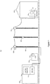
- FIG. 1 illustrates a simplified diagram of an asymmetric digital subscriber line (ADSL) network 100. Some elements have been omitted for simplicity, and conversely in some practical deployments, some elements shown are not required.
- ADSL digital subscriber line
- the network 100 including a customer's premises 102 connected to a telephone exchange 104 via a telephone line 106.
- the telephone line 106 is a twisted metallic pair made of copper or aluminium.
- a customer premises equipment CPE 108 such as a router or residential gateway, and comprises a DSL modem 110.
- the line 106 is connected to a digital subscriber line access multiplexer DSLAM 112.
- the DSLAM 112 is a network element that provides DSL services to connected lines and associated customer premises.
- the line 106 is thus also referred to as a digital subscriber line, or DSL line, though it will be appreciated that the line can also provide PSTN services.
- the exchange also houses electrical line test equipment 114, which can be connected to the line 106 by way of switching equipment in the exchange 104. Switching over to the test equipment 114 will disconnect the line from the DSLAM and thus disconnect the line from DSL services.
- the electrical line test equipment can measure various parameters associated with the line, including resistances, DC voltages, and capacitance.
- the line 106 passes through a number of connection points.
- the line 106 leaves the exchange and first passes through a Primary Cross-connection Point (PCP) 116, commonly referred to as a street cabinet, after it leaves the exchange 104.
- PCP Primary Cross-connection Point
- the cabling between the exchange 104 and the PCP 116 is largely to be found underground.
- the line 106 then goes overhead to a joint box 118 mounted on the top of a pole.
- the line continues to another pole and is jointed in another box 120 further down the pole.
- the line continues from there to yet another pole to an aerial Distribution Point (DP) 122.
- DP aerial Distribution Point
- the line 106 takes the form of an overhead drop wire, which terminates at the customer premises 102 at a network termination equipment (NTE) and onto the CPE 108 and modem 110.
- NTE network termination equipment
- connection point will have many lines passing through it, with the PCP 116 having the most, and the DP 122 having the fewest, as lines get routed to alternative destinations.
- connection point can be considered as a node or junction, as the line 106 is in practice made up of multiple sections of cable, and the joins between cable sections housed in the connection points.
- the CPE 108 further includes a control module 124.
- the control module 124 gathers various parameters and measurements associated with the line 106 via the modem 110, and processes them in accordance with the invention as described below.
- the control module 124 may be implemented as a software module incorporated into the firmware of the CPE 108.
- Sensor 126 is located at the site of the joint box 118, and sensor 128 at the PCP 116. Whilst only two sensors are shown here, more sensors can be used, and positioned elsewhere in the network 100. The locations of the sensors are preferably at one or more points along the line 106 that are most likely to experience weather impact, in particular moisture ingress. This is most likely to occur at junctions between sections of the cable that make up the line 106, for example in the PCP 116 or the joint box 118. Sensors could additionally or alternatively be placed at other distribution points (DPs) along the line. Furthermore, each sensor can be located externally or internally at the respective DP.
- DPs distribution points
- the present example shows a DSLAM 112 residing in the exchange 104
- the invention would still be applicable to configurations where the DSLAM is located elsewhere.
- the DSLAM 112 might be located in the PCP 116, an example of which is a roadside cabinet, which is typically located nearer the customer premises than the exchange.
- DSLAM like functionality can be provided by an MSAN (multi services access node), which also provides other capabilities such as voice.
- MSAN multi services access node
- the DSLAM and MSAN are both examples of aggregation transceiver devices, which effectively aggregate a number of DSL lines, terminating them at a plurality of modems housed within.
- the SNR margin is the difference between the measured SNR and the SNR required to operate the line at a specific synchronisation rate, where the measured SNR is an instantaneous measure of the ratio of the received wanted DSL signal power to unwanted interference signals or noise. For example, if the line is synchronised at 8Mbs and needs 35dB of SNR to operate at this rate, and the measured SNR is 41dB, then the SNR margin would be 6dB.
- the SNR margin is continuously monitored every 60 seconds over 24 hour cycles, and the results are gathered by the control module 124, which stores them for processing.
- the SNR margin measurements can be gathered more or less frequently depending on the configuration of the modem 110 in the CPE.
- the downstream SNR margin is used here, as it is the service on the downstream channel that a customer notices most, rather than the upstream channel.
- Figure 3 illustrates a graph of the (downstream) SNR margin over a 24 hour period for a line operating without any significant faults.
- the SNR margin exhibits a diurnal pattern (which is caused by radio interference increasing during the hours of darkness as a result of ionosphere effects) causing the SNR margin to drop between 8pm and 5am.
- the SNR margins from a large population of good lines are analysed in this way to determine SNR margin characteristics that are representative of the good lines.
- the SNR margin measurements can be taken over a number of days and averages taken, before being processed to identify the specific characteristics common to the good lines. In this example, the following characteristics are identified:
- the first characteristic reflects the diurnal variation over the course of a 24 hour period.
- the second characteristic reflects the gradual change in SNR margin that can take place.
- the third characteristic maps the minute by minute variation, usually due to background noise.
- SNR margin characteristics are used to generate test conditions with associated thresholds. Other characteristics might be identified and used as well or instead.
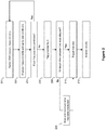
- the SNR margin measurements from step 200 are compared against these test conditions. A line with measurements that do not meet at least one of the test conditions is considered not to be operating normally and to be exhibiting a potential fault, and therefore tested with an electrical line test.
- test conditions and thresholds are set:
- test conditions are generated in advance but can be adjusted and updated by the network operator as required, and may be based on further inputs.
- the test conditions and predetermined thresholds are stored by the control module 124, and used in step 202. Note the thresholds are set slightly above the observed characteristics to account for minor variations that are not indicative of a fault.
- step 202 the control module 124 compares the SNR margin measurements against the test conditions. This is done continuously after each new SNR margin measurement is gathered from step 200, which in this example occurs every 60 seconds. Alternatively, a different period of time can be used between comparisons. However, the aim is to make the comparison using the current or most recent SNR margin measurements.
- step 204 if the measurements from the line 106 do pass all of the test conditions, then processing passes back to step 200, where the SNR margin continues to be monitored and analysed. If the measurements fail any one of the test conditions, then processing passes to step 206, as the line is deemed to be suffering from a potential fault.
- Figure 4 shows graphs of SNR margin measurements for an example line that fails to meet the test conditions.
- Figure 4 plots the (downstream) SNR margin reported every 60 seconds.
- the SNR margin characteristics of this line deviates from the target in a number of ways:
- the line actually re-syncs at a lower rate which is almost 1 Mbps lower than before but restores the SNR margin to the target 9dB.
- step 204 if the measurements fail at least one of the test conditions, as shown at certain times in the example illustrated in Figure 4 , then a potential fault is occurring and processing passes to step 206.
- SNR margin measurements that do not meet the test conditions can be referred to as SNR perturbations. In this example, it is the variations in the SNR margin measurements over a given period of time that are compared against the test conditions, which themselves are characterised over a period of time.
- step 206 the control module 124 flags a fault for the line 106, and an electrical line test needs to be triggered immediately to capture the instant the line is experiencing problems.
- a timer is used (counting down from a pre-set value) by the control module 124 to achieve this, but other methods could be used to delay the line test by the minimum time from the previous line test.
- the control module 124 determines if the minimum time between tests has elapsed. If it has, then processing passes directly to step 210 to trigger an electrical line test. If the minimum time has not elapsed, then the control module 124 waits until the minimum time has elapsed (step 209) before passing to step 210.
- an electrical line test is triggered. This can be done by the control unit 124 using an API running on a server on the network, which in turn can trigger the line test equipment 114. Alternatively, the control unit 124 can be configured to directly instruct the line test equipment 114 to perform the line test.
- the electrical line tests measure various parameters associated with the line, such as DC voltage A to earth, DC voltage B to earth, DC voltage A to B, capacitance A to earth, capacitance B to earth, capacitance A to B, resistance A to earth, and so on.
- step 212 The results are analysed in step 212. Some faults can be identified directly from analysis of parameters from the line test (using ranges and threshold values associated with known faults for example), though the specifics of this analysis and identification are not discussed here. Otherwise, other activities can be performed. For example, further fault events can be captured using the above method over a period of time, to build up a more detailed picture, which may result in improved diagnosis and an assessment on the impact to the DSL service of the fault level of service interruption. Alternatively, the fault event can be correlated with other information. Processing cycles back to step 200 after the line test is triggered in step 210.
- Atmospheric conditions can affect the operation of a DSL line.
- weather is dynamic and it is not always obvious that intermittent faults are being caused by weather.
- To assess whether a fault is correlated to the weather it is necessary to have nearby weather data available, the spatial distance and sample frequency will directly affect the correlation results.
- the network 100 in Figure 1 shows two sensors 126 and 128. These are used to assess the atmospheric moisture or wetness levels, as one particular problem that is encountered is water ingress on a line. Examples of the types of sensors that can be used include:
- the improved approach looks to correlate the atmospheric moisture levels, measured by one (or more) of sensors, with the SNR margin measurements on the line. If there is a correlation between the moisture levels and the SNR margin measurements, then the line is classified as having a weather related fault.
- a line test is triggered at a time when the SNR measurements fail to meet the test conditions described above, and whilst there is a correlation with the measured atmospheric moisture levels. The results of the line test in such a situation, together with the knowledge that the line may be experiencing a weather related fault, can lead to more focussed and accurate fault diagnosis.
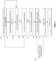
- the improved method is based on the main method described above, and summarised in Figure 2 , but includes some additional features that take into account an atmospheric moisture measure.
- the SNR margin measurement associated with the line 106 is gathered by the control module 124 from the modem 110.
- An atmospheric moisture measure is also collected from one of the sensors 126 and 128. Several sensors can be used, and the measurements averaged. In this example, a leaf wetness sensor is used, with the resulting leaf wetness measurements calibrated from 0 to 15, with 0 indicating dry and 15 indicated 100% saturated or wet. The leaf wetness measurements are gathered and stored by the control module 124.
- step 502 the resulting SNR margin measurements are analysed and compared by the control module 124 against the test conditions.
- the test conditions used in this example are the same as those described above. Also as before, the comparison is done after each new SNR margin measurement is gathered from step 500, which in this example occurs every 60 seconds, though other intervals can be used.
- step 504 if the SNR margin measurements from the line 106 do meet the test conditions, then processing passes back to step 500, where the SNR margin continues to be monitored and analysed every 60 seconds. Again, in this example, it is really the variations in the SNR margin measurements over a given period of time that are compared against the test conditions, which themselves are characterised over a period of time.
- step 505 determines whether there is a correlation between the SNR variations and the leaf wetness measurements.
- step 505 the moisture level measurements given by the leaf wetness sensors are analysed.
- the test is to see if the atmospheric moisture levels meet a certain threshold level - in this example, the threshold is set to the atmospheric moisture levels being high, at 100% saturation, or when leaf wetness measure of 15. Alternatively, the threshold could simply be set to anything non-zero/not dry.
- the moisture levels are high (i.e. leaf wetness is at 15)
- the line is classified as having a wet joint fault, and a line test should be triggered by moving to step 506. Otherwise processing passes back to step 500, and monitoring and analysis continue at regular intervals.
- the triggering of the line test should only occur whilst the line is experiencing a period of wetness (set at 100% saturation in this example) as identified by the leaf wetness measure.
- step 506 the control module 124 flags a wet joint fault for the line 106, and an electrical line test is triggered immediately to capture the instant the line is experiencing problems. However, and as described above, it is not ideal to run a line tests too frequently. Thus, in step 508, the control module 124 determines if the minimum time between tests has elapsed (see step 208), and if it has, then processing passes directly to step 510 to trigger an electrical line test. If the minimum time has not elapsed, then the control module 124 waits until the minimum time has elapsed (step 509) before passing to step 510.
- step 510 The line test triggered in step 510 and subsequent analysis in step 512 is as per steps 210 and 212 respectively of Figure 2 .
- Figure 6a shows a graph of SNR margin measurements over a 24 hour period for an example line
- Fig 6b the leaf wetness measurements for the same line. It can be seen from Fig 6a , that the SNR margin drops a little at around 07:00, when there is also a marginal leaf wetness measure. Then starting around 16:30, the SNR margin varies significantly, dropping progressively lower until 20:00 when the line resynchronises to a lower rate. The leaf wetness measure from around 16:30 moves from dry (0) to saturated (15) very quickly.
- step 504 the SNR variations are significant enough that the test conditions in step 504 are not met again. However, this time the moisture levels are high, with the leaf wetness sensor returning 15. Thus, processing passes to step 506, with the line flagged as experiencing a wet joint fault, and a line test triggered. After this point, the SNR margin variations remain significant for the next 4 hours or so, whilst the leaf wetness also remains high at 15, so line tests will be triggered regularly, at a rate capped by the minimum time between tests in step 508.
- a range of sensors are used.
- both a leaf wetness sensor and a rain sensor are used.
- the sensors are placed at the same point in the network somewhere along or near the line 106 (such as both at the PCP 116), or may be placed separately from each other (such as one at the PCP 116 and the other on the pole 118).
- Figure 7 is a flow chart illustrating the steps of this further improved method. In step 700, the SNR margin measurements are gathered from the line 106, as well as measurements from these two sensors.
- step 702 the resulting SNR margin measurements are analysed and compared by the control module 124 against the test conditions.
- step 704 if the SNR margin measurements from the line 106 do meet the test conditions, then processing passes back to step 700, where the SNR margin continues to be monitored and analysed repeatedly.
- step 706 the fault is assessed by determining the correlation, if any, between the SNR margin variations and the moisture level measurements. Using the resulting correlation results, a refined classification is generated for the fault.
- the correlation method is illustrated here with reference to an example line.
- Figure 8a shows a graph of SNR margin over a 24 hour period for an example line
- Fig 8b the moisture measurements for the line from the two sensors - leaf wetness levels and rain levels.
- the SNR margin shows minor variations, during which time the leaf wetness is also generally high. However, there is no rain measured during this period.
- the SNR margin shows a major variation and drops significantly, so much so that the DSL line actually resynchronises, during which time the leaf wetness levels are high, and the rain levels are also high during the same period.
- the correlation can be determined in various ways.
- One approach is to examine the measurements from the weather sensors (when the SNR margin variations do not meet the test conditions), and comparing the measurements to thresholds or ranges.
- the total correlation thus depends on the various measurements at a specific point in time.
- there is good correlation between the SNR margin variations and the leaf wetness levels but in the second period there is good correlation between the SNR margin variations and both the leaf wetness levels and rain levels.
- the degree of correlation between the SNR margin variations and the number of moisture level measurements is used to classify the line in step 708.
- the line 106 can be assigned a line fault classification that reflects the correlation.
- classifications is shown below:
- the method operates continuously by cycling back to step 700, and thus the generated line fault classification is updated continuously.
- the method will classify the line in Fig 8 with a class 2 fault up to around 06:30, and then around 16:00 the line will be classified with a class 1 fault, as only SNR perturbations are measured, but between 21:00 and 22:00, the line will be classed with a class 3 fault.
- each correlation can result in an individual correlation score of 1
- the final correlation is the sum of the individual correlation scores. For example, if SNR perturbations do not correlate with any of the moisture level measurements, then the individual correlations scores are 0, and the final correlation is 0. But if just one of either of moisture level measurements result in correlation with the SNR perturbations, then a single individual correlation score of 1 results, so the final correlation is 1. If both moisture level measurements correlate with the SNR perturbations, then two individual correlation scores result, which will result in a final correlation of 2. This approach gives scope for further moisture level measures or sensors to be used (e.g. a dew-point sensor), with the possibility of higher degrees of final correlation.
- a dew-point sensor e.g. a dew-point sensor
- the resulting classification can be used to trigger a suitable action in step 710.
- electrical line tests as described earlier can be set to only trigger for faults that have a certain classification. More specific testing or further an engineer visit can be allocated to lines that have classifications based on high correlations, which might be more problematic or difficult to resolve.
- Thresholds for wind speed can be set accordingly to determine correlation, such as corresponding to zero wind, low wind, and high wind.
- Exemplary embodiments of the invention are realised, at least in part, by executable computer program code which may be embodied in an application program data.
- executable computer program code When such computer program code is loaded into the memory of a processor in the control module 124, it provides a computer program code structure which is capable of performing at least part of the methods in accordance with the above described exemplary embodiments of the invention.
- computer program structure referred can correspond to the flow chart shown in Figure 2 , where each step of the flow chart can correspond to at least one line of computer program code and that such, in combination with the processor in the control module 124, provides apparatus for effecting the described process.
- computer program structure for the alternative methods can correspond to the flow charts shown in Figure 5 or Figure 7 .
Landscapes
- Engineering & Computer Science (AREA)
- Signal Processing (AREA)
- Computer Networks & Wireless Communication (AREA)
- Monitoring And Testing Of Exchanges (AREA)
Claims (5)
- Procédé de gestion d'une ligne d'abonné numérique (106) dans un réseau de télécommunications (100), comprenant :la mesure en continu (200) d'un paramètre de rapport signal-bruit associé à la ligne d'abonné numérique et l'identification de variations dans le paramètre de rapport signal-bruit ;la comparaison (202, 204) des variations avec une ou plusieurs condition(s) prédéterminée(s), dans lequel les conditions prédéterminées sont basées sur des caractéristiques de paramètre de rapport signal-bruit associées à une population de lignes fonctionnant sans un défaut ;le déclenchement (210) d'un test de ligne sur la ligne d'abonné numérique dès que les conditions prédéterminées ne sont pas satisfaites à l'étape de comparaison, et caractérisé en ce que le procédé comprend en outrela détermination d'une mesure d'humidité atmosphérique dans le réseau de télécommunications, et le déclenchement uniquement d'un test de ligne sur la ligne d'abonné numérique si les conditions prédéterminées ne sont pas satisfaites et que la mesure d'humidité atmosphérique satisfait un seuil prédéterminé.
- Procédé selon la revendication 1, dans lequel le seuil prédéterminé indique un niveau d'humidité élevée.
- Procédé selon la revendication 1 ou la revendication 2, dans lequel le paramètre de rapport signal-bruit est la marge du rapport signal-bruit.
- Procédé selon l'une quelconque revendication précédente, comprenant en outre de signaler un défaut sur la ligne si les conditions prédéterminées ne sont pas satisfaites.
- Unité de commande (124) pour gérer une ligne d'abonné numérique (106) dotée d'un moyen adapté pour :mesurer en continu (200) un paramètre de rapport signal-bruit associé à la ligne d'abonné numérique et identifier des variations dans le paramètre de rapport signal-bruit ;comparer (202, 204) les variations avec une ou plusieurs condition(s) prédéterminée(s), dans lequel les conditions prédéterminées sont basées sur des caractéristiques de paramètre de rapport signal-bruit associées à une population de lignes fonctionnant sans un défaut ;déclencher (210) un test de ligne sur la ligne d'abonné numérique dès que les conditions prédéterminées ne sont pas satisfaites, et caractérisé en ce que l'unité de commande est en outre adaptée pourdéterminer une mesure d'humidité atmosphérique dans le réseau de télécommunications, et déclencher uniquement un test de ligne sur la ligne d'abonné numérique si les conditions prédéterminées ne sont pas satisfaites et que la mesure d'humidité atmosphérique satisfait un seuil prédéterminé.
Applications Claiming Priority (2)
| Application Number | Priority Date | Filing Date | Title |
|---|---|---|---|
| EP14250114 | 2014-09-30 | ||
| PCT/EP2015/071256 WO2016050519A1 (fr) | 2014-09-30 | 2015-09-16 | Test de lignes à large bande optimisé |
Publications (2)
| Publication Number | Publication Date |
|---|---|
| EP3202129A1 EP3202129A1 (fr) | 2017-08-09 |
| EP3202129B1 true EP3202129B1 (fr) | 2018-06-27 |
Family
ID=51690308
Family Applications (1)
| Application Number | Title | Priority Date | Filing Date |
|---|---|---|---|
| EP15763607.7A Active EP3202129B1 (fr) | 2014-09-30 | 2015-09-16 | Test de ligne à large bande optimisée |
Country Status (3)
| Country | Link |
|---|---|
| US (1) | US9998590B2 (fr) |
| EP (1) | EP3202129B1 (fr) |
| WO (1) | WO2016050519A1 (fr) |
Families Citing this family (6)
| Publication number | Priority date | Publication date | Assignee | Title |
|---|---|---|---|---|
| EP3202128B1 (fr) * | 2014-09-30 | 2018-07-11 | British Telecommunications public limited company | Classification de défaut de ligne |
| US10194020B2 (en) * | 2015-09-30 | 2019-01-29 | British Telecommunications Public Limited Company | Line fault localisation |
| EP3669509A1 (fr) | 2017-08-14 | 2020-06-24 | British Telecommunications Public Limited Company | Procédés et appareil pour le codage de données audio et/ou vidéo |
| GB2572381B (en) * | 2018-03-28 | 2021-04-14 | British Telecomm | DSL line fault identification |
| CN113475052B (zh) | 2019-01-31 | 2023-06-06 | 英国电讯有限公司 | 对音频数据和/或视频数据进行编码的方法和装置 |
| EP3949133B1 (fr) * | 2019-03-29 | 2024-04-10 | British Telecommunications public limited company | Susceptibilité d'interférence de ligne dsl |
Family Cites Families (14)
| Publication number | Priority date | Publication date | Assignee | Title |
|---|---|---|---|---|
| US6970560B1 (en) * | 1999-11-11 | 2005-11-29 | Tokyo Electron Limited | Method and apparatus for impairment diagnosis in communication systems |
| US7564895B2 (en) * | 2001-03-29 | 2009-07-21 | Nortel Networks Limited | Method and apparatus for monitoring channel frequency response |
| US20030021391A1 (en) * | 2001-06-01 | 2003-01-30 | Rubin David A. | Method and apparatus for determining distance qualification and electrical qualification of a telephone line for high speed communications |
| EP1349355A1 (fr) * | 2002-03-28 | 2003-10-01 | BRITISH TELECOMMUNICATIONS public limited company | Procédé et dispositif de détection de défauts d'une ligne téléphonique |
| EP1569402A1 (fr) * | 2004-02-26 | 2005-08-31 | Alcatel | Modem numérique pour la ligne d'abonné avec attribution adaptative de bits, qui emploie un modèle d'etat de canal |
| US7881219B2 (en) * | 2006-04-13 | 2011-02-01 | Telefonaktiebolaget Lm Ericsson | Arrangement and method of configuring digital subscriber lines |
| CN101272160B (zh) * | 2007-03-20 | 2013-06-05 | 华为技术有限公司 | Dsl参考虚拟噪声的确定方法及装置、配置方法及系统 |
| US20080253079A1 (en) * | 2007-04-12 | 2008-10-16 | Robinson Ian N | Methods and systems of selecting functionality of a portable computer |
| BR112012012628A2 (pt) * | 2009-11-25 | 2019-09-24 | At&T Intelectual Property I L P | método e aparelho para detectar defeitos de fiação em uma linha de assinante digital. |
| WO2012091725A1 (fr) * | 2010-12-30 | 2012-07-05 | Adaptive Spectrum And Signal Alignment, Inc. | Centre de gestion pour un équipement installé dans les locaux d'un client de système de communication |
| US9060054B2 (en) * | 2012-03-19 | 2015-06-16 | Adaptive Spectrum And Signal Alignment, Inc. | System for diagnosing and optimizing vectored DSL lines |
| EP2645633A1 (fr) * | 2012-03-29 | 2013-10-02 | British Telecommunications Public Limited Company | Estimation de débit en ligne |
| US9420090B2 (en) | 2012-04-13 | 2016-08-16 | Adaptive Spectrum And Signal Alignment, Inc. | Diagnostic methods for twisted pair telephone lines based on line data distribution analysis |
| DE102013006548B4 (de) * | 2013-04-16 | 2022-02-03 | Dräger Safety AG & Co. KGaA | Messvorrichtung, Reaktionsträger und Messverfahren |
-
2015
- 2015-09-16 WO PCT/EP2015/071256 patent/WO2016050519A1/fr active Application Filing
- 2015-09-16 EP EP15763607.7A patent/EP3202129B1/fr active Active
- 2015-09-16 US US15/514,836 patent/US9998590B2/en active Active
Non-Patent Citations (1)
| Title |
|---|
| None * |
Also Published As
| Publication number | Publication date |
|---|---|
| US20170214791A1 (en) | 2017-07-27 |
| EP3202129A1 (fr) | 2017-08-09 |
| WO2016050519A1 (fr) | 2016-04-07 |
| US9998590B2 (en) | 2018-06-12 |
Similar Documents
| Publication | Publication Date | Title |
|---|---|---|
| EP3202129B1 (fr) | Test de ligne à large bande optimisée | |
| US10194020B2 (en) | Line fault localisation | |
| EP2882114A1 (fr) | Gestion de cycle de vie de défauts se produisant sur des fibres optiques | |
| EP3202128B1 (fr) | Classification de défaut de ligne | |
| US8447567B2 (en) | Measuring line performance | |
| US9178990B2 (en) | Systems and methods for characterizing loops based on single-ended line testing (SELT) | |
| US9584183B2 (en) | Fault identification using line attenuations | |
| US11140063B2 (en) | Dynamic subscriber network physical impairment detection techniques | |
| EP3949133B1 (fr) | Susceptibilité d'interférence de ligne dsl | |
| EP3383012A1 (fr) | Identification d'une interférence à large bande | |
| GB2542812A (en) | Line fault localisation | |
| US11089150B2 (en) | Method and network analyzer of evaluating a communication line | |
| CN111903064B (zh) | 确定存在和降低电力线路传输干扰的方法 | |
| EP2976839B1 (fr) | Identification de défauts de ligne à l'aide d'erreurs d'extrémité proche et distante | |
| EP3437202B1 (fr) | Estimation de la longueur de la ligne électrique d'une ligne d'abonné numérique | |
| GB2572381A (en) | DSL line fault identification | |
| EP2717486A1 (fr) | Dispositif et procédé permettant de détecter la présence d'une protection contre la surtension sur une ligne d'abonné numérique | |
| GB2582645A (en) | DSL line interference susceptibility | |
| GB2571259A (en) | Digital subscriber line interference identification | |
| EP2733891A1 (fr) | Appareil et procédé pour quantifier la dégradation de l'infrastructure d'un réseau |
Legal Events
| Date | Code | Title | Description |
|---|---|---|---|
| STAA | Information on the status of an ep patent application or granted ep patent |
Free format text: STATUS: THE INTERNATIONAL PUBLICATION HAS BEEN MADE |
|
| PUAI | Public reference made under article 153(3) epc to a published international application that has entered the european phase |
Free format text: ORIGINAL CODE: 0009012 |
|
| STAA | Information on the status of an ep patent application or granted ep patent |
Free format text: STATUS: REQUEST FOR EXAMINATION WAS MADE |
|
| 17P | Request for examination filed |
Effective date: 20170315 |
|
| AK | Designated contracting states |
Kind code of ref document: A1 Designated state(s): AL AT BE BG CH CY CZ DE DK EE ES FI FR GB GR HR HU IE IS IT LI LT LU LV MC MK MT NL NO PL PT RO RS SE SI SK SM TR |
|
| AX | Request for extension of the european patent |
Extension state: BA ME |
|
| DAV | Request for validation of the european patent (deleted) | ||
| DAX | Request for extension of the european patent (deleted) | ||
| RAP1 | Party data changed (applicant data changed or rights of an application transferred) |
Owner name: BRITISH TELECOMMUNICATIONS PUBLIC LIMITED COMPANY |
|
| GRAP | Despatch of communication of intention to grant a patent |
Free format text: ORIGINAL CODE: EPIDOSNIGR1 |
|
| STAA | Information on the status of an ep patent application or granted ep patent |
Free format text: STATUS: GRANT OF PATENT IS INTENDED |
|
| INTG | Intention to grant announced |
Effective date: 20180308 |
|
| GRAS | Grant fee paid |
Free format text: ORIGINAL CODE: EPIDOSNIGR3 |
|
| GRAA | (expected) grant |
Free format text: ORIGINAL CODE: 0009210 |
|
| STAA | Information on the status of an ep patent application or granted ep patent |
Free format text: STATUS: THE PATENT HAS BEEN GRANTED |
|
| AK | Designated contracting states |
Kind code of ref document: B1 Designated state(s): AL AT BE BG CH CY CZ DE DK EE ES FI FR GB GR HR HU IE IS IT LI LT LU LV MC MK MT NL NO PL PT RO RS SE SI SK SM TR |
|
| REG | Reference to a national code |
Ref country code: GB Ref legal event code: FG4D |
|
| REG | Reference to a national code |
Ref country code: AT Ref legal event code: REF Ref document number: 1013331 Country of ref document: AT Kind code of ref document: T Effective date: 20180715 |
|
| REG | Reference to a national code |
Ref country code: DE Ref legal event code: R096 Ref document number: 602015012817 Country of ref document: DE |
|
| REG | Reference to a national code |
Ref country code: IE Ref legal event code: FG4D |
|
| REG | Reference to a national code |
Ref country code: FR Ref legal event code: PLFP Year of fee payment: 4 |
|
| PG25 | Lapsed in a contracting state [announced via postgrant information from national office to epo] |
Ref country code: FI Free format text: LAPSE BECAUSE OF FAILURE TO SUBMIT A TRANSLATION OF THE DESCRIPTION OR TO PAY THE FEE WITHIN THE PRESCRIBED TIME-LIMIT Effective date: 20180627 Ref country code: NO Free format text: LAPSE BECAUSE OF FAILURE TO SUBMIT A TRANSLATION OF THE DESCRIPTION OR TO PAY THE FEE WITHIN THE PRESCRIBED TIME-LIMIT Effective date: 20180927 Ref country code: SE Free format text: LAPSE BECAUSE OF FAILURE TO SUBMIT A TRANSLATION OF THE DESCRIPTION OR TO PAY THE FEE WITHIN THE PRESCRIBED TIME-LIMIT Effective date: 20180627 Ref country code: LT Free format text: LAPSE BECAUSE OF FAILURE TO SUBMIT A TRANSLATION OF THE DESCRIPTION OR TO PAY THE FEE WITHIN THE PRESCRIBED TIME-LIMIT Effective date: 20180627 Ref country code: BG Free format text: LAPSE BECAUSE OF FAILURE TO SUBMIT A TRANSLATION OF THE DESCRIPTION OR TO PAY THE FEE WITHIN THE PRESCRIBED TIME-LIMIT Effective date: 20180927 |
|
| REG | Reference to a national code |
Ref country code: NL Ref legal event code: MP Effective date: 20180627 |
|
| REG | Reference to a national code |
Ref country code: LT Ref legal event code: MG4D |
|
| PG25 | Lapsed in a contracting state [announced via postgrant information from national office to epo] |
Ref country code: HR Free format text: LAPSE BECAUSE OF FAILURE TO SUBMIT A TRANSLATION OF THE DESCRIPTION OR TO PAY THE FEE WITHIN THE PRESCRIBED TIME-LIMIT Effective date: 20180627 Ref country code: RS Free format text: LAPSE BECAUSE OF FAILURE TO SUBMIT A TRANSLATION OF THE DESCRIPTION OR TO PAY THE FEE WITHIN THE PRESCRIBED TIME-LIMIT Effective date: 20180627 Ref country code: LV Free format text: LAPSE BECAUSE OF FAILURE TO SUBMIT A TRANSLATION OF THE DESCRIPTION OR TO PAY THE FEE WITHIN THE PRESCRIBED TIME-LIMIT Effective date: 20180627 Ref country code: GR Free format text: LAPSE BECAUSE OF FAILURE TO SUBMIT A TRANSLATION OF THE DESCRIPTION OR TO PAY THE FEE WITHIN THE PRESCRIBED TIME-LIMIT Effective date: 20180928 |
|
| REG | Reference to a national code |
Ref country code: AT Ref legal event code: MK05 Ref document number: 1013331 Country of ref document: AT Kind code of ref document: T Effective date: 20180627 |
|
| PG25 | Lapsed in a contracting state [announced via postgrant information from national office to epo] |
Ref country code: NL Free format text: LAPSE BECAUSE OF FAILURE TO SUBMIT A TRANSLATION OF THE DESCRIPTION OR TO PAY THE FEE WITHIN THE PRESCRIBED TIME-LIMIT Effective date: 20180627 |
|
| PG25 | Lapsed in a contracting state [announced via postgrant information from national office to epo] |
Ref country code: RO Free format text: LAPSE BECAUSE OF FAILURE TO SUBMIT A TRANSLATION OF THE DESCRIPTION OR TO PAY THE FEE WITHIN THE PRESCRIBED TIME-LIMIT Effective date: 20180627 Ref country code: SK Free format text: LAPSE BECAUSE OF FAILURE TO SUBMIT A TRANSLATION OF THE DESCRIPTION OR TO PAY THE FEE WITHIN THE PRESCRIBED TIME-LIMIT Effective date: 20180627 Ref country code: IS Free format text: LAPSE BECAUSE OF FAILURE TO SUBMIT A TRANSLATION OF THE DESCRIPTION OR TO PAY THE FEE WITHIN THE PRESCRIBED TIME-LIMIT Effective date: 20181027 Ref country code: AT Free format text: LAPSE BECAUSE OF FAILURE TO SUBMIT A TRANSLATION OF THE DESCRIPTION OR TO PAY THE FEE WITHIN THE PRESCRIBED TIME-LIMIT Effective date: 20180627 Ref country code: EE Free format text: LAPSE BECAUSE OF FAILURE TO SUBMIT A TRANSLATION OF THE DESCRIPTION OR TO PAY THE FEE WITHIN THE PRESCRIBED TIME-LIMIT Effective date: 20180627 Ref country code: PL Free format text: LAPSE BECAUSE OF FAILURE TO SUBMIT A TRANSLATION OF THE DESCRIPTION OR TO PAY THE FEE WITHIN THE PRESCRIBED TIME-LIMIT Effective date: 20180627 Ref country code: CZ Free format text: LAPSE BECAUSE OF FAILURE TO SUBMIT A TRANSLATION OF THE DESCRIPTION OR TO PAY THE FEE WITHIN THE PRESCRIBED TIME-LIMIT Effective date: 20180627 |
|
| PG25 | Lapsed in a contracting state [announced via postgrant information from national office to epo] |
Ref country code: SM Free format text: LAPSE BECAUSE OF FAILURE TO SUBMIT A TRANSLATION OF THE DESCRIPTION OR TO PAY THE FEE WITHIN THE PRESCRIBED TIME-LIMIT Effective date: 20180627 Ref country code: IT Free format text: LAPSE BECAUSE OF FAILURE TO SUBMIT A TRANSLATION OF THE DESCRIPTION OR TO PAY THE FEE WITHIN THE PRESCRIBED TIME-LIMIT Effective date: 20180627 Ref country code: ES Free format text: LAPSE BECAUSE OF FAILURE TO SUBMIT A TRANSLATION OF THE DESCRIPTION OR TO PAY THE FEE WITHIN THE PRESCRIBED TIME-LIMIT Effective date: 20180627 |
|
| REG | Reference to a national code |
Ref country code: DE Ref legal event code: R097 Ref document number: 602015012817 Country of ref document: DE |
|
| PG25 | Lapsed in a contracting state [announced via postgrant information from national office to epo] |
Ref country code: MC Free format text: LAPSE BECAUSE OF FAILURE TO SUBMIT A TRANSLATION OF THE DESCRIPTION OR TO PAY THE FEE WITHIN THE PRESCRIBED TIME-LIMIT Effective date: 20180627 |
|
| REG | Reference to a national code |
Ref country code: CH Ref legal event code: PL |
|
| PLBE | No opposition filed within time limit |
Free format text: ORIGINAL CODE: 0009261 |
|
| STAA | Information on the status of an ep patent application or granted ep patent |
Free format text: STATUS: NO OPPOSITION FILED WITHIN TIME LIMIT |
|
| PG25 | Lapsed in a contracting state [announced via postgrant information from national office to epo] |
Ref country code: DK Free format text: LAPSE BECAUSE OF FAILURE TO SUBMIT A TRANSLATION OF THE DESCRIPTION OR TO PAY THE FEE WITHIN THE PRESCRIBED TIME-LIMIT Effective date: 20180627 |
|
| 26N | No opposition filed |
Effective date: 20190328 |
|
| REG | Reference to a national code |
Ref country code: BE Ref legal event code: MM Effective date: 20180930 |
|
| REG | Reference to a national code |
Ref country code: IE Ref legal event code: MM4A |
|
| PG25 | Lapsed in a contracting state [announced via postgrant information from national office to epo] |
Ref country code: LU Free format text: LAPSE BECAUSE OF NON-PAYMENT OF DUE FEES Effective date: 20180916 |
|
| PG25 | Lapsed in a contracting state [announced via postgrant information from national office to epo] |
Ref country code: IE Free format text: LAPSE BECAUSE OF NON-PAYMENT OF DUE FEES Effective date: 20180916 |
|
| PG25 | Lapsed in a contracting state [announced via postgrant information from national office to epo] |
Ref country code: SI Free format text: LAPSE BECAUSE OF FAILURE TO SUBMIT A TRANSLATION OF THE DESCRIPTION OR TO PAY THE FEE WITHIN THE PRESCRIBED TIME-LIMIT Effective date: 20180627 Ref country code: BE Free format text: LAPSE BECAUSE OF NON-PAYMENT OF DUE FEES Effective date: 20180930 Ref country code: CH Free format text: LAPSE BECAUSE OF NON-PAYMENT OF DUE FEES Effective date: 20180930 Ref country code: LI Free format text: LAPSE BECAUSE OF NON-PAYMENT OF DUE FEES Effective date: 20180930 |
|
| PG25 | Lapsed in a contracting state [announced via postgrant information from national office to epo] |
Ref country code: AL Free format text: LAPSE BECAUSE OF FAILURE TO SUBMIT A TRANSLATION OF THE DESCRIPTION OR TO PAY THE FEE WITHIN THE PRESCRIBED TIME-LIMIT Effective date: 20180627 |
|
| PG25 | Lapsed in a contracting state [announced via postgrant information from national office to epo] |
Ref country code: MT Free format text: LAPSE BECAUSE OF NON-PAYMENT OF DUE FEES Effective date: 20180916 |
|
| PG25 | Lapsed in a contracting state [announced via postgrant information from national office to epo] |
Ref country code: TR Free format text: LAPSE BECAUSE OF FAILURE TO SUBMIT A TRANSLATION OF THE DESCRIPTION OR TO PAY THE FEE WITHIN THE PRESCRIBED TIME-LIMIT Effective date: 20180627 |
|
| PG25 | Lapsed in a contracting state [announced via postgrant information from national office to epo] |
Ref country code: PT Free format text: LAPSE BECAUSE OF FAILURE TO SUBMIT A TRANSLATION OF THE DESCRIPTION OR TO PAY THE FEE WITHIN THE PRESCRIBED TIME-LIMIT Effective date: 20180627 |
|
| PG25 | Lapsed in a contracting state [announced via postgrant information from national office to epo] |
Ref country code: MK Free format text: LAPSE BECAUSE OF NON-PAYMENT OF DUE FEES Effective date: 20180627 Ref country code: CY Free format text: LAPSE BECAUSE OF FAILURE TO SUBMIT A TRANSLATION OF THE DESCRIPTION OR TO PAY THE FEE WITHIN THE PRESCRIBED TIME-LIMIT Effective date: 20180627 Ref country code: HU Free format text: LAPSE BECAUSE OF FAILURE TO SUBMIT A TRANSLATION OF THE DESCRIPTION OR TO PAY THE FEE WITHIN THE PRESCRIBED TIME-LIMIT; INVALID AB INITIO Effective date: 20150916 |
|
| P01 | Opt-out of the competence of the unified patent court (upc) registered |
Effective date: 20230623 |
|
| PGFP | Annual fee paid to national office [announced via postgrant information from national office to epo] |
Ref country code: GB Payment date: 20230823 Year of fee payment: 9 |
|
| PGFP | Annual fee paid to national office [announced via postgrant information from national office to epo] |
Ref country code: FR Payment date: 20230822 Year of fee payment: 9 Ref country code: DE Payment date: 20230822 Year of fee payment: 9 |