EP3202014B1 - Steuervorrichtung für einen lichtmaschinenregler eines kraftfahrzeugs und lichtmaschine mit entsprechdendem regler - Google Patents
Steuervorrichtung für einen lichtmaschinenregler eines kraftfahrzeugs und lichtmaschine mit entsprechdendem regler Download PDFInfo
- Publication number
- EP3202014B1 EP3202014B1 EP15781129.0A EP15781129A EP3202014B1 EP 3202014 B1 EP3202014 B1 EP 3202014B1 EP 15781129 A EP15781129 A EP 15781129A EP 3202014 B1 EP3202014 B1 EP 3202014B1
- Authority
- EP
- European Patent Office
- Prior art keywords
- voltage
- regulator
- alternator
- motor vehicle
- fault
- Prior art date
- Legal status (The legal status is an assumption and is not a legal conclusion. Google has not performed a legal analysis and makes no representation as to the accuracy of the status listed.)
- Not-in-force
Links
Images

Classifications
-
- H—ELECTRICITY
- H02—GENERATION; CONVERSION OR DISTRIBUTION OF ELECTRIC POWER
- H02P—CONTROL OR REGULATION OF ELECTRIC MOTORS, ELECTRIC GENERATORS OR DYNAMO-ELECTRIC CONVERTERS; CONTROLLING TRANSFORMERS, REACTORS OR CHOKE COILS
- H02P9/00—Arrangements for controlling electric generators for the purpose of obtaining a desired output
-
- H—ELECTRICITY
- H02—GENERATION; CONVERSION OR DISTRIBUTION OF ELECTRIC POWER
- H02J—ELECTRIC POWER NETWORKS; CIRCUIT ARRANGEMENTS OR SYSTEMS FOR SUPPLYING OR DISTRIBUTING ELECTRIC POWER; SYSTEMS FOR STORING ELECTRIC ENERGY
- H02J7/00—Circuit arrangements for charging or discharging batteries or for supplying loads from batteries
- H02J7/14—Circuit arrangements for charging or discharging batteries or for supplying loads from batteries for charging batteries from dynamo-electric generators driven at varying speed, e.g. on vehicle
- H02J7/1469—Regulation of the charging current or voltage otherwise than by variation of field
- H02J7/1492—Regulation of the charging current or voltage otherwise than by variation of field by means of controlling devices between the generator output and the battery
-
- G—PHYSICS
- G01—MEASURING; TESTING
- G01R—MEASURING ELECTRIC VARIABLES; MEASURING MAGNETIC VARIABLES
- G01R31/00—Arrangements for testing electric properties; Arrangements for locating electric faults; Arrangements for electrical testing characterised by what is being tested not provided for elsewhere
- G01R31/34—Testing dynamo-electric machines
- G01R31/343—Testing dynamo-electric machines in operation
-
- H—ELECTRICITY
- H02—GENERATION; CONVERSION OR DISTRIBUTION OF ELECTRIC POWER
- H02K—DYNAMO-ELECTRIC MACHINES
- H02K11/00—Structural association of dynamo-electric machines with electric components or with devices for shielding, monitoring or protection
- H02K11/30—Structural association with control circuits or drive circuits
-
- H—ELECTRICITY
- H02—GENERATION; CONVERSION OR DISTRIBUTION OF ELECTRIC POWER
- H02P—CONTROL OR REGULATION OF ELECTRIC MOTORS, ELECTRIC GENERATORS OR DYNAMO-ELECTRIC CONVERTERS; CONTROLLING TRANSFORMERS, REACTORS OR CHOKE COILS
- H02P9/00—Arrangements for controlling electric generators for the purpose of obtaining a desired output
- H02P9/02—Details of the control
-
- H—ELECTRICITY
- H02—GENERATION; CONVERSION OR DISTRIBUTION OF ELECTRIC POWER
- H02J—ELECTRIC POWER NETWORKS; CIRCUIT ARRANGEMENTS OR SYSTEMS FOR SUPPLYING OR DISTRIBUTING ELECTRIC POWER; SYSTEMS FOR STORING ELECTRIC ENERGY
- H02J7/00—Circuit arrangements for charging or discharging batteries or for supplying loads from batteries
- H02J7/14—Circuit arrangements for charging or discharging batteries or for supplying loads from batteries for charging batteries from dynamo-electric generators driven at varying speed, e.g. on vehicle
- H02J7/16—Regulation of the charging current or voltage by variation of field
-
- H—ELECTRICITY
- H02—GENERATION; CONVERSION OR DISTRIBUTION OF ELECTRIC POWER
- H02J—ELECTRIC POWER NETWORKS; CIRCUIT ARRANGEMENTS OR SYSTEMS FOR SUPPLYING OR DISTRIBUTING ELECTRIC POWER; SYSTEMS FOR STORING ELECTRIC ENERGY
- H02J7/00—Circuit arrangements for charging or discharging batteries or for supplying loads from batteries
- H02J7/60—Circuit arrangements for charging or discharging batteries or for supplying loads from batteries including safety or protection arrangements
-
- H—ELECTRICITY
- H02—GENERATION; CONVERSION OR DISTRIBUTION OF ELECTRIC POWER
- H02J—ELECTRIC POWER NETWORKS; CIRCUIT ARRANGEMENTS OR SYSTEMS FOR SUPPLYING OR DISTRIBUTING ELECTRIC POWER; SYSTEMS FOR STORING ELECTRIC ENERGY
- H02J7/00—Circuit arrangements for charging or discharging batteries or for supplying loads from batteries
- H02J7/80—Circuit arrangements for charging or discharging batteries or for supplying loads from batteries including monitoring or indicating arrangements
-
- H—ELECTRICITY
- H02—GENERATION; CONVERSION OR DISTRIBUTION OF ELECTRIC POWER
- H02K—DYNAMO-ELECTRIC MACHINES
- H02K2211/00—Specific aspects not provided for in the other groups of this subclass relating to measuring or protective devices or electric components
-
- H—ELECTRICITY
- H02—GENERATION; CONVERSION OR DISTRIBUTION OF ELECTRIC POWER
- H02P—CONTROL OR REGULATION OF ELECTRIC MOTORS, ELECTRIC GENERATORS OR DYNAMO-ELECTRIC CONVERTERS; CONTROLLING TRANSFORMERS, REACTORS OR CHOKE COILS
- H02P2101/00—Special adaptation of control arrangements for generators
- H02P2101/45—Special adaptation of control arrangements for generators for motor vehicles, e.g. car alternators
-
- Y—GENERAL TAGGING OF NEW TECHNOLOGICAL DEVELOPMENTS; GENERAL TAGGING OF CROSS-SECTIONAL TECHNOLOGIES SPANNING OVER SEVERAL SECTIONS OF THE IPC; TECHNICAL SUBJECTS COVERED BY FORMER USPC CROSS-REFERENCE ART COLLECTIONS [XRACs] AND DIGESTS
- Y02—TECHNOLOGIES OR APPLICATIONS FOR MITIGATION OR ADAPTATION AGAINST CLIMATE CHANGE
- Y02T—CLIMATE CHANGE MITIGATION TECHNOLOGIES RELATED TO TRANSPORTATION
- Y02T10/00—Road transport of goods or passengers
- Y02T10/80—Technologies aiming to reduce greenhouse gasses emissions common to all road transportation technologies
- Y02T10/92—Energy efficient charging or discharging systems for batteries, ultracapacitors, supercapacitors or double-layer capacitors specially adapted for vehicles
Definitions
- the present invention relates to a control device of a regulator of an alternator of a motor vehicle, and the alternator comprising the regulator adapted to this control device.
- a regulator of a motor vehicle alternator is put into operation at the initiative of the driver by a vehicle ignition key.
- the controller is connected to the ignition key via a fault warning light.
- the circuitry of the regulator is constantly powered, but must go from a state of rest or standby, of reduced consumption, to an active state when it detects that the ignition key is closed.
- the central problem of such detection lies in the discrimination that must be made between the case where the key is open and the lamp extinguished, in which case a terminal of the lamp side regulator is at the potential of a mass through a resistance, and the case where the key is closed but the lamp, because of the existence of a fault, is lit, in which case the terminal of the lamp side regulator is at a fixed potential, for example by a waste voltage of a semiconductor switching element which supplies the lamp. And the lower this waste voltage, the more the potential of the regulator side lamp terminal is close to that of the mass, which makes it difficult to discriminate between the open and closed states of the key.
- the company VALEO ELECTRIC EQUIPMENTS MOTOR solves this difficulty by implementing in a sensing circuit a differential amplifier controlling the semiconductor switching element of the lamp from a difference between a voltage level of the lamp terminal on the regulator side and a reference level, so as to maintain the potential from this terminal to a level sufficient not to disable the controller while the alternator has a fault but the ignition key is closed.
- the discrimination between the open and closed states of the key is also made difficult by the existence of a leakage resistance between a terminal of the battery supplying the lamp and the lamp terminal of the regulator side, shorting the key of contact.
- Such a leakage resistance which is likely to appear in particular under the effect of conductive deposits, such as salt bridges created when the vehicle is exposed to salt spray, may have a value of 10 K ⁇ , or as low as 1 kOhms.
- this leakage resistance as a function of ambient conditions makes a voltage divider bridge formed by this leakage resistor and the fixed pulling resistor random, making reliable detection of the open and closed states of the key based on a comparison to a single and fixed reference level.
- EP0783994 a control device of a vehicle alternator voltage regulator.
- EP0822654 a control device of a vehicle alternator voltage regulator.
- the present invention aims to provide a solution to the known problems of the state of the prior art mentioned above, in particular the problem of parasitic leakage currents.
- the invention relates to a device for controlling a regulator of an alternator of a motor vehicle of the type of those comprising, on the one hand, a control circuit generating an activation command of the regulator in bringing to a first voltage higher than a predetermined high reference voltage a single-wire bidirectional communication line connected to, on the other hand, a detection circuit of a state of this activation command.
- the detection circuit includes means for generating a fault signal from a flag signaling a failure of the alternator by connecting the communication line to a ground by at least one semiconductor switching element. As a result, the communication line is raised to a second voltage lower than a predetermined fault voltage lower than the high reference voltage.
- the control circuit comprises means for detecting this fault signal.
- control circuit further transmits a modulated pulse width signal with a maximum amplitude greater than the high reference voltage and a minimum amplitude lower than a reference voltage. predetermined lower than the fault voltage, a duty cycle of this reference signal being representative of a regulator setpoint voltage.
- the detection circuit further comprises, according to the invention, a first voltage comparator, activated by activation means in the absence of failure of the alternator, which compares a voltage level. of the communication line at a first predetermined voltage threshold.
- the detection circuit further comprises a second voltage comparator activated by these activation means in the event of a failure of the alternator and comparing the voltage level of the communication line. at a second predetermined voltage threshold.
- the activation means are formed by a first AND logic gate connected as input to a first output of the first voltage comparator and to a flag complementary to the flag signaling the failure of the alternator, and by a second logic AND gate connected as input to a second output of the second voltage comparator and to the flag.
- the first and second logic gates AND are connected at the output to an OR logic gate so as to reconstitute the reference signal emitted by the control circuit in the form of a pulse width modulated signal (PWM, acronym for "Pulse”). Width Modulation "in English terminology).
- PWM pulse width modulated signal
- the detection circuit further comprises a differential voltage amplifier amplifying a difference between the voltage level of the communication line and a third predetermined voltage threshold, activated by the flag signaling the failure of the alternator and controlling the semiconductor switching element.
- the detection circuit further comprises a current comparator activated by the activation means in the event of a failure of the alternator and comparing a value of the current flowing in the semiconductor switching at a predetermined current threshold.
- the activation means are formed by a two-way multiplexer controlled by the flag signaling the failure of the alternator, and input connected to a first output of the first voltage comparator and at a second output of the current comparator so as to reconstruct the reference signal outputted from the control circuit.
- this current comparator comprises for example a current mirror.
- the invention also relates to a motor vehicle alternator of the type of those comprising an integrated regulator.
- this regulator comprises a detection circuit of a control device as described above.
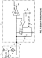
- connection terminal 3 is connected to the indicator 4 of the vehicle dashboard and the key switch 5, direct or indirect.
- the activation of the regulator is effected by the detection of a first voltage corresponding substantially to the battery voltage level VBat on a communication line 6 connecting the control circuit 1 to the detection circuit 2 during the switching of the key switch. 5.
- the detection circuit 2 of the regulator draws the potential of the communication line 6 to ground with a semiconductor switching element 7, formed by a power transistor of MOSFET type. , controlled by a flag LAMP_ON provided on a status terminal 8 by the faulty alternator, so as to thereby carry a second voltage of the communication line 6 below a predetermined fault voltage and to circulate a current in the line of communication 6 to report this defect.
- the voltage level V of the communication line 6 In order not to deactivate the regulator during a fault indication, the voltage level V of the communication line 6 must not fall below a predetermined detection threshold Vs.
- This voltage level is then maintained around for example 1.2 V by a control means 9, 10 of the power transistor 7, formed by a differential amplifier 9 amplifying a difference between the voltage level of the communication line 6 and the detection threshold Vs provided by a voltage reference of 1.2 V for example.
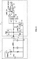
- the control device shown on the Figure 1 is changed as shown on the Figure 2 for implementing a communication protocol between the control circuit 1 and the detection circuit 2 enabling a motor control module (not shown) to set a reference voltage V0 of the regulator on a control terminal 15.
- the pilot light 4 is replaced by a load resistor 4, of the order of 470 ⁇ for example, and a control circuit 16 which transmits on the communication line 6 a PWM modulated reference signal.
- the value of the duty cycle corresponds to the voltage regulation setpoint.
- An amplitude of the setpoint signal depends on the operating mode of the controller.
- the control circuit 16 In normal mode without indication of a fault, the control circuit 16 imposes a first voltage higher than a high reference voltage on the communication line 6. When the high draw is released by the control circuit 16, the pulling resistor 11 to the regulator mass reduces the voltage level V on the communication line 6 to a second voltage lower than a low reference voltage, close to 0 V.
- a maximum of the reference signal is limited to the detection threshold Vs, that is to say to 1.2 V for example, by the control means 9, 10 of the transistor of power 7, while a minimum of this setpoint signal is brought back below the fault voltage, at substantially 0 V, by both the power transistor 7 and the pulling resistor 11 to ground.
- the detection of the reference signal by the regulator is effected without modification of its detection circuit 2 with respect to the known assembly of the state of the art shown in FIG. Figure 1 .
- the voltage level on the communication line 6 drops back to 0 V and crosses the detection threshold Vs closing the key 5.
- the reference signal transmitted by the control circuit 16 can therefore be detected by the first comparator circuit 14, recomposed on the output terminal 13 and sent to a logic control circuit of the regulator, which must be adapted to calculate the set voltage V0 to be applied to the alternator from this signal detected COM_DETECT.
- the control circuit 1 Since the battery charge indicator light 4 on the dashboard of the vehicle is no longer directly switched by the detection circuit 2 of the regulator, the control circuit 1 must be able to detect the draw below the fault voltage, c that is to say less than 1 V, of the communication line 6 when signaling the failure of the alternator. To do this, a second hysteresis comparator circuit 17 placed in the control circuit 1 detects the absence of activity on the communication line 6 and can trace this information to a cabin control module (not shown) via a terminal of signaling 18.
- the transmission to the regulator of the setpoint voltage V0 supplied by the engine control module and the fault indication transmitted by the regulator to the habitable control module can be simultaneous: the communication line 6 between the control circuit 1 and the circuit Detection 2 is a full duplex link.
- the disadvantage of this general approach is its sensitivity to leakage currents that may appear during the life of the control device 1, 2 between a power terminal B + A of the alternator supplying the battery and the connection terminal 3 from the regulator to the control circuit 1, for example because of a salt bridge, type of problems already indicated in the preamble.
- the equivalent leakage resistance 19 tends to raise the voltage level on the communication line 6 to a low state of the setpoint signal.
- the effect can be that the minimum of the reference signal is always higher than the low reference voltage and therefore the duty cycle of the reference signal can no longer be interpreted.
- the controller could also no longer return to standby mode during passive vehicle life cycles, which would help to discharge the battery.
- specifications of the communication protocol take into account a possible rise in the voltage level V to the low state of the setpoint signal in normal operating mode by appropriately selecting the high and low reference voltages, as well as the fault voltage.
- the high reference voltage is equal to 3.5 V for example, the low reference voltage is equal to 1.5 V for example and the fault voltage is of the order of 1 V.
- the minimum of the setpoint signal is thus included in 0 V and 1.5 V for example according to these specifications in normal operating mode. But in the event of a fault, the voltage level V is always less than 1 V. There is therefore no detection range common to both operating modes.
- two detection methods are implemented in the detection circuit 2 of the control device 1, 2 of a regulator according to the invention: one when the amplitude of the signals is important, the other in the fault with lower voltage levels.
- the detection circuit 2 comprises first and second voltage comparators 20, 21 for the setpoint signal in the two operating modes
- the first voltage comparator 20 compares the voltage level V on the communication line 6 with a first predetermined voltage threshold V1 of 2.5 V provided by a first reference source 22.
- the second voltage comparator 21 compares the voltage level V on the communication line 6 with a second predetermined voltage threshold V2 of 0.65 V provided by a second reference source 23.
- the reconstituted reference signal COM_DETECT is supplied on the output terminal 13 by the first voltage comparator 20 or the second voltage comparator 21 as a function of the mode.
- the differential voltage amplifier 9 driving the power transistor 7 amplifies the difference between the voltage level V of the communication line 6 and a third predetermined voltage threshold V3 of 0.9 V supplied by a third reference source 28.
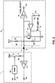
- a second particular embodiment of the invention schematically shown on the Figure 4 , provides an answer in this case.
- the detection circuit 2 comprises the first voltage comparator 20 already implemented in the first embodiment of the invention for detecting the setpoint signal in normal operating mode.
- the voltage sensing threshold is ideally above the ground offset voltage and below the high reference voltage.
- the high reference voltage equal to 3.5 V and the low reference voltage equal to 1.5 V of the communication protocol are most often suitable by choosing without modification the first predetermined voltage threshold which is compared with the voltage level of the communication line equal to 2.5 V.
- the detection circuit 2 comprises a current comparator 29.
- This current comparator 29 performs a comparison between a value of the current flowing in the power transistor 7, switching the communication line 6 to ground via a drain resistor 30, of the order of 100 ⁇ , and a current threshold. predetermined.
- This current threshold corresponds to a minimum value of the current making it possible to reduce the voltage level V on the communication line 6 to the fault voltage, ie 1 V.
- the current comparator 29 comprises a current mirror, that is to say that it comprises a signal transistor of a type identical to the power transistor 7, but of smaller dimensions, connected in parallel to the power transistor 7. It is therefore a drain-source current of this signal transistor, proportional to the current flowing in the power transistor 7 which allows comparison with the predetermined current threshold.
- the controller When changing its state in fault indication mode, the controller switches from the implementation of the first voltage comparator 20 to the implementation of the current comparator 29 for reading the duty cycle.
- the setpoint signal is reconstituted COM_DETECT on the output terminal 13 by a two-way multiplexer 31 controlled by the flag LAMP_ON and input connected to a first output of the first voltage comparator 20 and the current comparator 29.
- the output signals of the first voltage comparator 20 and the current comparator 29 must overlap at the time of the flip-flop between modes of operation. Thus the discontinuity will be minimized in the reading of the duty cycle. To do this, switching from the normal mode to the default mode is synchronized with a low state of the setpoint signal.
- the detection circuit 2 of the control device 1, 2 of a regulator according to the invention is embodied in the form of an ASIC.
- ASIC Application Specific Integrated Circuit
- This type of integrated circuit makes it easy to comply with the various specifications to be provided by automobile manufacturers, in particular concerning the communication protocol and relating to the high reference voltage, the low reference voltage, and the fault voltage, to satisfy all the demand for new generation programmable generators.
- the values of the passive electronic components such as the resistors 4, 11, 19, 30 and the types of active electronic components 7, 9, 14, 17, 20, 21, 24, 25, 26, 27, 28, 29 , 31 shown are just examples: the skilled person will use as much as necessary other electronic components to perform the same functions.
Landscapes
- Engineering & Computer Science (AREA)
- Power Engineering (AREA)
- Physics & Mathematics (AREA)
- General Physics & Mathematics (AREA)
- Control Of Charge By Means Of Generators (AREA)
- Control Of Eletrric Generators (AREA)
Claims (10)
- Steuervorrichtung (1, 2) für einen Regler einer Lichtmaschine eines Kraftfahrzeugs vom Typ derjenigen, welche einerseits eine Steuerschaltung (1) aufweisen, die einen Befehl zur Aktivierung (KEY_ON) des Reglers erzeugt, indem sie eine erste Spannung, die höher als eine vorbestimmte hohe Referenzspannung ist, an eine eindrähtige bidirektionale Kommunikationsleitung (6) anlegt, die andererseits mit einer Schaltung zur Detektion (2) eines Zustands (KEY_DETECT) des Aktivierungsbefehls (KEY_ON) verbunden ist, wobei die Detektionsschaltung (2) Mittel zur Erzeugung (7, 9) eines Fehlersignals ausgehend von einem Flag (LAMP_ON), das einen Ausfall der Lichtmaschine signalisiert, durch Verbinden der Kommunikationsleitung (6) mit einer Masse durch wenigstens ein Halbleiterschaltelement (7) aufweist, wodurch an die Kommunikationsleitung (6) eine zweite Spannung angelegt wird, die niedriger als eine vorbestimmte Fehlerspannung ist, die niedriger als die hohe Referenzspannung ist, und wobei die Steuerschaltung (1) Mittel zur Detektion (4) des Fehlersignals umfasst,
dadurch gekennzeichnet, dass die Steuerschaltung (1) außerdem über die Kommunikationsleitung ein pulsweitenmoduliertes Sollwertsignal überträgt, welches ein Maximum aufweist, das höher als die hohe Referenzspannung ist, und ein Minimum, das niedriger als eine vorbestimmte niedrige Referenzspannung ist, die höher als die Fehlerspannung ist, wobei ein Tastverhältnis des Sollwertsignals für eine Sollwertspannung (V0) des Reglers repräsentativ ist. - Steuervorrichtung (1, 2) für einen Regler einer Lichtmaschine eines Kraftfahrzeugs nach dem vorhergehenden Anspruch 1, dadurch gekennzeichnet, dass die Detektionsschaltung (2) außerdem einen ersten Spannungskomparator (20) umfasst, der bei Nichtvorliegen eines Ausfalls der Lichtmaschine von Aktivierungsmitteln (24, 25) aktiviert wird und einen Spannungspegel (V) der Kommunikationsleitung (6) mit einem vorbestimmten ersten Spannungsschwellenwert (V1) vergleicht.
- Steuervorrichtung (1, 2) für einen Regler einer Lichtmaschine eines Kraftfahrzeugs nach dem vorhergehenden Anspruch 2, dadurch gekennzeichnet, dass die Detektionsschaltung (2) außerdem einen zweiten Spannungskomparator (21) umfasst, der im Falle eines Ausfalls der Lichtmaschine von den Aktivierungsmitteln (26) aktiviert wird und den Spannungspegel (V) der Kommunikationsleitung (6) mit einem vorbestimmten zweiten Spannungsschwellenwert (V2) vergleicht.
- Steuervorrichtung (1, 2) für einen Regler einer Lichtmaschine eines Kraftfahrzeugs nach dem vorhergehenden Anspruch 3, dadurch gekennzeichnet, dass die Aktivierungsmittel (24, 25, 26) von einem ersten UND-Gatter (24), das am Eingang mit einem ersten Ausgang des ersten Spannungskomparators (20) und mit einem zu dem Flag (LAMP_ON) komplementären Flag verbunden ist, und von einem zweiten UND-Gatter (26), das am Eingang mit einem zweiten Ausgang des zweiten Spannungskomparators (21) und mit dem Flag (LAMP_ON) verbunden ist, gebildet werden, wobei das erste und das zweite UND-Gatter (24, 26) am Ausgang mit einem ODER-Gatter (27) verbunden sind, um so das Sollwertsignal (COM_DETECT) abzuleiten.
- Steuervorrichtung (1, 2) für einen Regler einer Lichtmaschine eines Kraftfahrzeugs nach einem der vorhergehenden Ansprüche 3 oder 4, dadurch gekennzeichnet, dass die Detektionsschaltung (2) außerdem einen Spannungsdifferenzverstärker (9) umfasst, der eine Differenz zwischen dem Spannungspegel (V) der Kommunikationsleitung (6) und einem vorbestimmten dritten Spannungsschwellenwert (V3) vergleicht, durch das Flag (LAMP_ON) aktiviert wird und das Schaltelement (7) steuert.
- Steuervorrichtung (1, 2) für einen Regler einer Lichtmaschine eines Kraftfahrzeugs nach dem vorhergehenden Anspruch 2, dadurch gekennzeichnet, dass die Detektionsschaltung (2) außerdem einen Stromkomparator (29) umfasst, der im Falle eines Ausfalls der Lichtmaschine von den Aktivierungsmitteln (31) aktiviert wird und einen Wert des Stroms, der in dem Schaltelement (7) fließt, mit einem vorbestimmten Stromschwellenwert vergleicht.
- Steuervorrichtung (1, 2) für einen Regler einer Lichtmaschine eines Kraftfahrzeugs nach dem vorhergehenden Anspruch 6, dadurch gekennzeichnet, dass die Aktivierungsmittel (31) von einem Zweiwege-Multiplexer (31) gebildet werden, der von dem Flag (LAMP_ON) gesteuert wird und am Eingang mit einem ersten Ausgang des ersten Spannungskomparators (20) und mit einem zweiten Ausgang des Stromkomparators (29) verbunden ist, um so das Sollwertsignal (COM_DETECT) abzuleiten.
- Steuervorrichtung (1, 2) für einen Regler einer Lichtmaschine eines Kraftfahrzeugs nach einem der vorhergehenden Ansprüche 6 oder 7, dadurch gekennzeichnet, dass der Stromkomparator (29) einen Stromspiegel umfasst.
- Steuervorrichtung (1, 2) für einen Regler einer Lichtmaschine eines Kraftfahrzeugs nach dem vorhergehenden Anspruch 8, dadurch gekennzeichnet, dass die vorbestimmte hohe und die vorbestimmte niedrige Referenzspannung, die Fehlerspannung, der erste, zweite und dritte vorbestimmte Spannungsschwellenwert ungefähr 3,5 V, 1,5 V, 1,0 V, 2,5 V, 0,65 V bzw. 0,9 V betragen.
- Lichtmaschine eines Kraftfahrzeugs vom Typ derjenigen, welche einen integrierten Regler aufweisen, dadurch gekennzeichnet, dass der Regler eine Detektionsschaltung (2) einer Steuervorrichtung (1, 2) nach einem der vorhergehenden Ansprüche 1 bis 9 umfasst.
Applications Claiming Priority (2)
| Application Number | Priority Date | Filing Date | Title |
|---|---|---|---|
| FR1459227A FR3026574B1 (fr) | 2014-09-30 | 2014-09-30 | Dispositif de commande d'un regulateur d'un alternateur d'un vehicule automobile et alternateur comprenant le regulateur correspondant |
| PCT/FR2015/052599 WO2016051075A1 (fr) | 2014-09-30 | 2015-09-29 | Dispositif de commande d'un regulateur d'un alternateur d'un vehicule automobile et alternateur comprenant le regulateur correspondant |
Publications (2)
| Publication Number | Publication Date |
|---|---|
| EP3202014A1 EP3202014A1 (de) | 2017-08-09 |
| EP3202014B1 true EP3202014B1 (de) | 2018-07-18 |
Family
ID=52423824
Family Applications (1)
| Application Number | Title | Priority Date | Filing Date |
|---|---|---|---|
| EP15781129.0A Not-in-force EP3202014B1 (de) | 2014-09-30 | 2015-09-29 | Steuervorrichtung für einen lichtmaschinenregler eines kraftfahrzeugs und lichtmaschine mit entsprechdendem regler |
Country Status (5)
| Country | Link |
|---|---|
| US (1) | US10193479B2 (de) |
| EP (1) | EP3202014B1 (de) |
| CN (1) | CN107078670A (de) |
| FR (1) | FR3026574B1 (de) |
| WO (1) | WO2016051075A1 (de) |
Families Citing this family (3)
| Publication number | Priority date | Publication date | Assignee | Title |
|---|---|---|---|---|
| KR102757507B1 (ko) * | 2017-02-13 | 2025-01-20 | 삼성전자주식회사 | 전력 소모를 감소한 역전압 모니터링 회로 및 이를 포함하는 반도체 장치 |
| DE102018118057A1 (de) * | 2018-07-26 | 2020-01-30 | Valeo Schalter Und Sensoren Gmbh | System zur automatisch überwachten Fahrzeugzustandssignalisierung und Verfahren zur Überwachung einer Fahrzeugzustandssignalisierungsvorrichtung |
| EP3627970B1 (de) * | 2018-09-24 | 2021-05-05 | Valeo Iluminacion | Detektorvorrichtung und kraftfahrzeugbeleuchtungsvorrichtung |
Family Cites Families (14)
| Publication number | Priority date | Publication date | Assignee | Title |
|---|---|---|---|---|
| US4000453A (en) * | 1975-12-17 | 1976-12-28 | General Motors Corporation | Storage battery charging system with alternator output fault indicating circuit |
| US4323837A (en) * | 1978-07-24 | 1982-04-06 | Nissan Motor Company, Limited | Power supply circuit for automotive vehicles |
| US4584515A (en) * | 1984-12-31 | 1986-04-22 | Motorola, Inc. | Re-regulation circuit for automobile tachometer detection circuit |
| FR2674063B1 (fr) * | 1991-03-12 | 1993-07-09 | Valeo Equip Electr Moteur | Circuit de detection de l'etat d'un interrupteur, notamment d'une cle de contact dans un regulateur de tension d'alternateur. |
| DE4311670A1 (de) * | 1993-04-08 | 1994-10-13 | Bosch Gmbh Robert | Spannungsregler zur Regelung der Ausgangsspannung eines Generators |
| FR2724268B1 (fr) | 1994-09-05 | 1997-10-10 | Valeo Equip Electr Moteur | Circuit de detection de la fermeture d'une cle de contact pour la commande d'un regulateur de la charge d'une batterie pour un alternateur, equipe de moyens de derivation des courants de fuite parasites |
| JPH0879981A (ja) * | 1994-09-06 | 1996-03-22 | Hitachi Ltd | 車両用交流発電機の異常判定方法 |
| JP3531771B2 (ja) * | 1994-12-28 | 2004-05-31 | 株式会社デンソー | 車両用充電装置 |
| DE59606547D1 (de) * | 1996-01-12 | 2001-04-12 | Bayerische Motoren Werke Ag | Steuerungssystem für einen Generator eines Kraftfahrzeuges |
| JP3518183B2 (ja) * | 1996-08-01 | 2004-04-12 | 株式会社デンソー | 車両用発電機の制御装置及びそれを用いた車両用発電装置 |
| JP2009303427A (ja) * | 2008-06-16 | 2009-12-24 | Mitsutoyo Corp | モータ駆動装置 |
| FR2949914B1 (fr) * | 2009-09-07 | 2014-11-21 | Valeo Equip Electr Moteur | Alternateur a redressement synchrone pour vehicule automobile, equipe de moyens electroniques de gestion de defauts |
| FR2976422B1 (fr) * | 2011-06-08 | 2014-10-31 | Valeo Equip Electr Moteur | Procede de controle d'un couple resistant d'un alternateur de vehicule automobile, et systeme de mise en oeuvre de ce procede |
| CN102684226A (zh) * | 2012-05-30 | 2012-09-19 | 大连美恒电气有限公司 | 一种可自并联向电网回馈电能的节能装置和方法 |
-
2014
- 2014-09-30 FR FR1459227A patent/FR3026574B1/fr not_active Expired - Fee Related
-
2015
- 2015-09-29 US US15/515,792 patent/US10193479B2/en not_active Expired - Fee Related
- 2015-09-29 EP EP15781129.0A patent/EP3202014B1/de not_active Not-in-force
- 2015-09-29 WO PCT/FR2015/052599 patent/WO2016051075A1/fr not_active Ceased
- 2015-09-29 CN CN201580049587.8A patent/CN107078670A/zh active Pending
Non-Patent Citations (1)
| Title |
|---|
| None * |
Also Published As
| Publication number | Publication date |
|---|---|
| US10193479B2 (en) | 2019-01-29 |
| FR3026574A1 (fr) | 2016-04-01 |
| EP3202014A1 (de) | 2017-08-09 |
| FR3026574B1 (fr) | 2016-10-28 |
| CN107078670A (zh) | 2017-08-18 |
| US20170310259A1 (en) | 2017-10-26 |
| WO2016051075A1 (fr) | 2016-04-07 |
Similar Documents
| Publication | Publication Date | Title |
|---|---|---|
| FR2523297A1 (fr) | Dispositif indicateur de faible niveau de carburant | |
| EP3202014B1 (de) | Steuervorrichtung für einen lichtmaschinenregler eines kraftfahrzeugs und lichtmaschine mit entsprechdendem regler | |
| EP2861450B1 (de) | Verfahren und system zur desaktivierung und aktivierung eines steuermoduls eines elektrischen fahrzeuges | |
| EP2766212A2 (de) | Sicheres verfahren zum abschneiden der stromversorgung eines elektromotors und entsprechende vorrichtung | |
| EP2561595B1 (de) | Verfahren zur steuerung der regelung der lichtmaschine eines kraftfahrzeugs und zugehörige vorrichtungen | |
| EP3028356B1 (de) | System zur verwaltung einer versorgungsspannung eines stromnetzes an bord eines kraftfahrzeugs | |
| EP2859217B1 (de) | Anlassverfahren einer brennkraftmaschine, system und steuergerät davon | |
| EP0505234B1 (de) | Schaltkreis zur Erkennung eines Schalterzustandes, namentlich eines Zündschlüssels in einem Spannungsregler eines Wechselstromgenerators | |
| FR3056709A1 (fr) | Pulseur d'air pour vehicule automobile alimente par deux reseaux d'alimentation electriques | |
| EP2481190A1 (de) | Steuerungsvorrichtung zum zurückstellen eines elektronischen elements eines kommunikationsnetzwerks vor dem neustart | |
| EP3272192A1 (de) | Diagnosevorrichtung | |
| FR2976151A1 (fr) | Dispositif de commutation d'une charge auxiliaire d'un bloc de leds. | |
| FR2966653A1 (fr) | Filtre de tension, commande | |
| FR2960298A1 (fr) | Procede de detection de defaut de connexion pour capteur de batterie dans un vehicule | |
| EP3744157B1 (de) | Verfahren zur diagnose von lösbaren lichtquellen für ein fahrzeug | |
| WO2008074952A1 (fr) | Procede et dispositif de detection de la defaillance du circuit d'excitation d'un alternateur polyphase | |
| FR2810494A1 (fr) | Circuit d'eclairage de lampe a decharge | |
| EP3646364B1 (de) | Elektrisches system zur steuerung eines funktionselements und system zum antrieb der räder eines kraftfahrzeugs | |
| FR2710886A1 (fr) | Système de clignotement de changement de direction et d'avertissement pour un véhicule automobile. | |
| FR2920883A1 (fr) | Procede de detection d'une defaillance sur un systeme d'alimentation d'une charge electrique. | |
| FR3056876A1 (fr) | Dispositif de chauffage electrique pour vehicule automobile alimente par deux reseaux d'alimentation electiques | |
| WO2025078345A1 (fr) | Dispositif lumineux ayant deux commandes | |
| Gupta | Method for Detecting the Head Lamp Switch Failure or Wiring Harness Failure and Controlling the Exterior and Interior Lights Using Intelligent Light Sensor | |
| WO2020260271A1 (fr) | Commutateur electronique | |
| FR3007345A1 (fr) | Dispositif de verrouillage d'organes electriques d'un vehicule via une communication numerique |
Legal Events
| Date | Code | Title | Description |
|---|---|---|---|
| PUAI | Public reference made under article 153(3) epc to a published international application that has entered the european phase |
Free format text: ORIGINAL CODE: 0009012 |
|
| 17P | Request for examination filed |
Effective date: 20170303 |
|
| AK | Designated contracting states |
Kind code of ref document: A1 Designated state(s): AL AT BE BG CH CY CZ DE DK EE ES FI FR GB GR HR HU IE IS IT LI LT LU LV MC MK MT NL NO PL PT RO RS SE SI SK SM TR |
|
| AX | Request for extension of the european patent |
Extension state: BA ME |
|
| DAV | Request for validation of the european patent (deleted) | ||
| DAX | Request for extension of the european patent (deleted) | ||
| GRAP | Despatch of communication of intention to grant a patent |
Free format text: ORIGINAL CODE: EPIDOSNIGR1 |
|
| RIC1 | Information provided on ipc code assigned before grant |
Ipc: H02J 7/14 20060101AFI20180112BHEP Ipc: H02J 7/16 20060101ALI20180112BHEP Ipc: H02P 9/02 20060101ALI20180112BHEP Ipc: H02K 11/30 20160101ALI20180112BHEP |
|
| INTG | Intention to grant announced |
Effective date: 20180213 |
|
| GRAS | Grant fee paid |
Free format text: ORIGINAL CODE: EPIDOSNIGR3 |
|
| GRAA | (expected) grant |
Free format text: ORIGINAL CODE: 0009210 |
|
| AK | Designated contracting states |
Kind code of ref document: B1 Designated state(s): AL AT BE BG CH CY CZ DE DK EE ES FI FR GB GR HR HU IE IS IT LI LT LU LV MC MK MT NL NO PL PT RO RS SE SI SK SM TR |
|
| REG | Reference to a national code |
Ref country code: GB Ref legal event code: FG4D Free format text: NOT ENGLISH |
|
| REG | Reference to a national code |
Ref country code: CH Ref legal event code: EP |
|
| REG | Reference to a national code |
Ref country code: IE Ref legal event code: FG4D Free format text: LANGUAGE OF EP DOCUMENT: FRENCH |
|
| REG | Reference to a national code |
Ref country code: AT Ref legal event code: REF Ref document number: 1020402 Country of ref document: AT Kind code of ref document: T Effective date: 20180815 |
|
| REG | Reference to a national code |
Ref country code: DE Ref legal event code: R096 Ref document number: 602015013814 Country of ref document: DE |
|
| REG | Reference to a national code |
Ref country code: FR Ref legal event code: PLFP Year of fee payment: 4 |
|
| REG | Reference to a national code |
Ref country code: NL Ref legal event code: MP Effective date: 20180718 |
|
| REG | Reference to a national code |
Ref country code: LT Ref legal event code: MG4D |
|
| REG | Reference to a national code |
Ref country code: AT Ref legal event code: MK05 Ref document number: 1020402 Country of ref document: AT Kind code of ref document: T Effective date: 20180718 |
|
| PG25 | Lapsed in a contracting state [announced via postgrant information from national office to epo] |
Ref country code: NL Free format text: LAPSE BECAUSE OF FAILURE TO SUBMIT A TRANSLATION OF THE DESCRIPTION OR TO PAY THE FEE WITHIN THE PRESCRIBED TIME-LIMIT Effective date: 20180718 |
|
| PG25 | Lapsed in a contracting state [announced via postgrant information from national office to epo] |
Ref country code: IS Free format text: LAPSE BECAUSE OF FAILURE TO SUBMIT A TRANSLATION OF THE DESCRIPTION OR TO PAY THE FEE WITHIN THE PRESCRIBED TIME-LIMIT Effective date: 20181118 Ref country code: PL Free format text: LAPSE BECAUSE OF FAILURE TO SUBMIT A TRANSLATION OF THE DESCRIPTION OR TO PAY THE FEE WITHIN THE PRESCRIBED TIME-LIMIT Effective date: 20180718 Ref country code: SE Free format text: LAPSE BECAUSE OF FAILURE TO SUBMIT A TRANSLATION OF THE DESCRIPTION OR TO PAY THE FEE WITHIN THE PRESCRIBED TIME-LIMIT Effective date: 20180718 Ref country code: RS Free format text: LAPSE BECAUSE OF FAILURE TO SUBMIT A TRANSLATION OF THE DESCRIPTION OR TO PAY THE FEE WITHIN THE PRESCRIBED TIME-LIMIT Effective date: 20180718 Ref country code: FI Free format text: LAPSE BECAUSE OF FAILURE TO SUBMIT A TRANSLATION OF THE DESCRIPTION OR TO PAY THE FEE WITHIN THE PRESCRIBED TIME-LIMIT Effective date: 20180718 Ref country code: GR Free format text: LAPSE BECAUSE OF FAILURE TO SUBMIT A TRANSLATION OF THE DESCRIPTION OR TO PAY THE FEE WITHIN THE PRESCRIBED TIME-LIMIT Effective date: 20181019 Ref country code: NO Free format text: LAPSE BECAUSE OF FAILURE TO SUBMIT A TRANSLATION OF THE DESCRIPTION OR TO PAY THE FEE WITHIN THE PRESCRIBED TIME-LIMIT Effective date: 20181018 Ref country code: AT Free format text: LAPSE BECAUSE OF FAILURE TO SUBMIT A TRANSLATION OF THE DESCRIPTION OR TO PAY THE FEE WITHIN THE PRESCRIBED TIME-LIMIT Effective date: 20180718 Ref country code: LT Free format text: LAPSE BECAUSE OF FAILURE TO SUBMIT A TRANSLATION OF THE DESCRIPTION OR TO PAY THE FEE WITHIN THE PRESCRIBED TIME-LIMIT Effective date: 20180718 Ref country code: BG Free format text: LAPSE BECAUSE OF FAILURE TO SUBMIT A TRANSLATION OF THE DESCRIPTION OR TO PAY THE FEE WITHIN THE PRESCRIBED TIME-LIMIT Effective date: 20181018 |
|
| PG25 | Lapsed in a contracting state [announced via postgrant information from national office to epo] |
Ref country code: LV Free format text: LAPSE BECAUSE OF FAILURE TO SUBMIT A TRANSLATION OF THE DESCRIPTION OR TO PAY THE FEE WITHIN THE PRESCRIBED TIME-LIMIT Effective date: 20180718 Ref country code: HR Free format text: LAPSE BECAUSE OF FAILURE TO SUBMIT A TRANSLATION OF THE DESCRIPTION OR TO PAY THE FEE WITHIN THE PRESCRIBED TIME-LIMIT Effective date: 20180718 Ref country code: AL Free format text: LAPSE BECAUSE OF FAILURE TO SUBMIT A TRANSLATION OF THE DESCRIPTION OR TO PAY THE FEE WITHIN THE PRESCRIBED TIME-LIMIT Effective date: 20180718 |
|
| REG | Reference to a national code |
Ref country code: DE Ref legal event code: R097 Ref document number: 602015013814 Country of ref document: DE |
|
| PG25 | Lapsed in a contracting state [announced via postgrant information from national office to epo] |
Ref country code: MC Free format text: LAPSE BECAUSE OF FAILURE TO SUBMIT A TRANSLATION OF THE DESCRIPTION OR TO PAY THE FEE WITHIN THE PRESCRIBED TIME-LIMIT Effective date: 20180718 Ref country code: RO Free format text: LAPSE BECAUSE OF FAILURE TO SUBMIT A TRANSLATION OF THE DESCRIPTION OR TO PAY THE FEE WITHIN THE PRESCRIBED TIME-LIMIT Effective date: 20180718 Ref country code: CZ Free format text: LAPSE BECAUSE OF FAILURE TO SUBMIT A TRANSLATION OF THE DESCRIPTION OR TO PAY THE FEE WITHIN THE PRESCRIBED TIME-LIMIT Effective date: 20180718 Ref country code: ES Free format text: LAPSE BECAUSE OF FAILURE TO SUBMIT A TRANSLATION OF THE DESCRIPTION OR TO PAY THE FEE WITHIN THE PRESCRIBED TIME-LIMIT Effective date: 20180718 Ref country code: EE Free format text: LAPSE BECAUSE OF FAILURE TO SUBMIT A TRANSLATION OF THE DESCRIPTION OR TO PAY THE FEE WITHIN THE PRESCRIBED TIME-LIMIT Effective date: 20180718 Ref country code: IT Free format text: LAPSE BECAUSE OF FAILURE TO SUBMIT A TRANSLATION OF THE DESCRIPTION OR TO PAY THE FEE WITHIN THE PRESCRIBED TIME-LIMIT Effective date: 20180718 |
|
| REG | Reference to a national code |
Ref country code: CH Ref legal event code: PL |
|
| PLBE | No opposition filed within time limit |
Free format text: ORIGINAL CODE: 0009261 |
|
| STAA | Information on the status of an ep patent application or granted ep patent |
Free format text: STATUS: NO OPPOSITION FILED WITHIN TIME LIMIT |
|
| PG25 | Lapsed in a contracting state [announced via postgrant information from national office to epo] |
Ref country code: DK Free format text: LAPSE BECAUSE OF FAILURE TO SUBMIT A TRANSLATION OF THE DESCRIPTION OR TO PAY THE FEE WITHIN THE PRESCRIBED TIME-LIMIT Effective date: 20180718 Ref country code: SK Free format text: LAPSE BECAUSE OF FAILURE TO SUBMIT A TRANSLATION OF THE DESCRIPTION OR TO PAY THE FEE WITHIN THE PRESCRIBED TIME-LIMIT Effective date: 20180718 Ref country code: SM Free format text: LAPSE BECAUSE OF FAILURE TO SUBMIT A TRANSLATION OF THE DESCRIPTION OR TO PAY THE FEE WITHIN THE PRESCRIBED TIME-LIMIT Effective date: 20180718 |
|
| REG | Reference to a national code |
Ref country code: BE Ref legal event code: MM Effective date: 20180930 |
|
| 26N | No opposition filed |
Effective date: 20190423 |
|
| REG | Reference to a national code |
Ref country code: IE Ref legal event code: MM4A |
|
| PG25 | Lapsed in a contracting state [announced via postgrant information from national office to epo] |
Ref country code: LU Free format text: LAPSE BECAUSE OF NON-PAYMENT OF DUE FEES Effective date: 20180929 |
|
| PG25 | Lapsed in a contracting state [announced via postgrant information from national office to epo] |
Ref country code: IE Free format text: LAPSE BECAUSE OF NON-PAYMENT OF DUE FEES Effective date: 20180929 |
|
| PG25 | Lapsed in a contracting state [announced via postgrant information from national office to epo] |
Ref country code: CH Free format text: LAPSE BECAUSE OF NON-PAYMENT OF DUE FEES Effective date: 20180930 Ref country code: LI Free format text: LAPSE BECAUSE OF NON-PAYMENT OF DUE FEES Effective date: 20180930 Ref country code: SI Free format text: LAPSE BECAUSE OF FAILURE TO SUBMIT A TRANSLATION OF THE DESCRIPTION OR TO PAY THE FEE WITHIN THE PRESCRIBED TIME-LIMIT Effective date: 20180718 Ref country code: BE Free format text: LAPSE BECAUSE OF NON-PAYMENT OF DUE FEES Effective date: 20180930 |
|
| PGFP | Annual fee paid to national office [announced via postgrant information from national office to epo] |
Ref country code: FR Payment date: 20190930 Year of fee payment: 5 Ref country code: DE Payment date: 20190913 Year of fee payment: 5 |
|
| PG25 | Lapsed in a contracting state [announced via postgrant information from national office to epo] |
Ref country code: MT Free format text: LAPSE BECAUSE OF FAILURE TO SUBMIT A TRANSLATION OF THE DESCRIPTION OR TO PAY THE FEE WITHIN THE PRESCRIBED TIME-LIMIT Effective date: 20180718 |
|
| PG25 | Lapsed in a contracting state [announced via postgrant information from national office to epo] |
Ref country code: TR Free format text: LAPSE BECAUSE OF FAILURE TO SUBMIT A TRANSLATION OF THE DESCRIPTION OR TO PAY THE FEE WITHIN THE PRESCRIBED TIME-LIMIT Effective date: 20180718 |
|
| PG25 | Lapsed in a contracting state [announced via postgrant information from national office to epo] |
Ref country code: PT Free format text: LAPSE BECAUSE OF FAILURE TO SUBMIT A TRANSLATION OF THE DESCRIPTION OR TO PAY THE FEE WITHIN THE PRESCRIBED TIME-LIMIT Effective date: 20180718 |
|
| PG25 | Lapsed in a contracting state [announced via postgrant information from national office to epo] |
Ref country code: MK Free format text: LAPSE BECAUSE OF NON-PAYMENT OF DUE FEES Effective date: 20180718 Ref country code: HU Free format text: LAPSE BECAUSE OF FAILURE TO SUBMIT A TRANSLATION OF THE DESCRIPTION OR TO PAY THE FEE WITHIN THE PRESCRIBED TIME-LIMIT; INVALID AB INITIO Effective date: 20150929 Ref country code: CY Free format text: LAPSE BECAUSE OF FAILURE TO SUBMIT A TRANSLATION OF THE DESCRIPTION OR TO PAY THE FEE WITHIN THE PRESCRIBED TIME-LIMIT Effective date: 20180718 |
|
| GBPC | Gb: european patent ceased through non-payment of renewal fee |
Effective date: 20190929 |
|
| PG25 | Lapsed in a contracting state [announced via postgrant information from national office to epo] |
Ref country code: GB Free format text: LAPSE BECAUSE OF NON-PAYMENT OF DUE FEES Effective date: 20190929 |
|
| REG | Reference to a national code |
Ref country code: DE Ref legal event code: R119 Ref document number: 602015013814 Country of ref document: DE |
|
| PG25 | Lapsed in a contracting state [announced via postgrant information from national office to epo] |
Ref country code: FR Free format text: LAPSE BECAUSE OF NON-PAYMENT OF DUE FEES Effective date: 20200930 Ref country code: DE Free format text: LAPSE BECAUSE OF NON-PAYMENT OF DUE FEES Effective date: 20210401 |
|
| P01 | Opt-out of the competence of the unified patent court (upc) registered |
Effective date: 20230528 |