EP3201732B1 - Haptic interface providing improved control of the haptic sensation - Google Patents
Haptic interface providing improved control of the haptic sensation Download PDFInfo
- Publication number
- EP3201732B1 EP3201732B1 EP15784581.9A EP15784581A EP3201732B1 EP 3201732 B1 EP3201732 B1 EP 3201732B1 EP 15784581 A EP15784581 A EP 15784581A EP 3201732 B1 EP3201732 B1 EP 3201732B1
- Authority
- EP
- European Patent Office
- Prior art keywords
- user
- interacting
- value
- speed
- actuation
- Prior art date
- Legal status (The legal status is an assumption and is not a legal conclusion. Google has not performed a legal analysis and makes no representation as to the accuracy of the status listed.)
- Active
Links
- 230000035807 sensation Effects 0.000 title 1
- 230000003993 interaction Effects 0.000 claims description 75
- 239000012530 fluid Substances 0.000 claims description 42
- 238000000034 method Methods 0.000 claims description 7
- 238000013519 translation Methods 0.000 claims description 7
- 239000000463 material Substances 0.000 claims description 4
- 238000012360 testing method Methods 0.000 description 40
- 238000004422 calculation algorithm Methods 0.000 description 25
- 230000035945 sensitivity Effects 0.000 description 7
- 238000004364 calculation method Methods 0.000 description 5
- 238000001514 detection method Methods 0.000 description 5
- 238000006073 displacement reaction Methods 0.000 description 5
- 238000005259 measurement Methods 0.000 description 5
- 230000036316 preload Effects 0.000 description 5
- 230000007423 decrease Effects 0.000 description 4
- 238000009877 rendering Methods 0.000 description 4
- 208000031968 Cadaver Diseases 0.000 description 3
- 230000000694 effects Effects 0.000 description 3
- 230000003071 parasitic effect Effects 0.000 description 3
- 238000012937 correction Methods 0.000 description 2
- 238000010008 shearing Methods 0.000 description 2
- 229910000838 Al alloy Inorganic materials 0.000 description 1
- 230000001594 aberrant effect Effects 0.000 description 1
- 238000004378 air conditioning Methods 0.000 description 1
- 230000015556 catabolic process Effects 0.000 description 1
- 238000006731 degradation reaction Methods 0.000 description 1
- 230000001419 dependent effect Effects 0.000 description 1
- 230000005684 electric field Effects 0.000 description 1
- 239000007788 liquid Substances 0.000 description 1
- 239000000696 magnetic material Substances 0.000 description 1
- 238000012986 modification Methods 0.000 description 1
- 230000004048 modification Effects 0.000 description 1
- 230000003287 optical effect Effects 0.000 description 1
- 238000011144 upstream manufacturing Methods 0.000 description 1
Images


Classifications
-
- G—PHYSICS
- G05—CONTROLLING; REGULATING
- G05G—CONTROL DEVICES OR SYSTEMS INSOFAR AS CHARACTERISED BY MECHANICAL FEATURES ONLY
- G05G5/00—Means for preventing, limiting or returning the movements of parts of a control mechanism, e.g. locking controlling member
- G05G5/03—Means for enhancing the operator's awareness of arrival of the controlling member at a command or datum position; Providing feel, e.g. means for creating a counterforce
-
- B—PERFORMING OPERATIONS; TRANSPORTING
- B60—VEHICLES IN GENERAL
- B60T—VEHICLE BRAKE CONTROL SYSTEMS OR PARTS THEREOF; BRAKE CONTROL SYSTEMS OR PARTS THEREOF, IN GENERAL; ARRANGEMENT OF BRAKING ELEMENTS ON VEHICLES IN GENERAL; PORTABLE DEVICES FOR PREVENTING UNWANTED MOVEMENT OF VEHICLES; VEHICLE MODIFICATIONS TO FACILITATE COOLING OF BRAKES
- B60T13/00—Transmitting braking action from initiating means to ultimate brake actuator with power assistance or drive; Brake systems incorporating such transmitting means, e.g. air-pressure brake systems
- B60T13/10—Transmitting braking action from initiating means to ultimate brake actuator with power assistance or drive; Brake systems incorporating such transmitting means, e.g. air-pressure brake systems with fluid assistance, drive, or release
- B60T13/66—Electrical control in fluid-pressure brake systems
-
- B—PERFORMING OPERATIONS; TRANSPORTING
- B60—VEHICLES IN GENERAL
- B60K—ARRANGEMENT OR MOUNTING OF PROPULSION UNITS OR OF TRANSMISSIONS IN VEHICLES; ARRANGEMENT OR MOUNTING OF PLURAL DIVERSE PRIME-MOVERS IN VEHICLES; AUXILIARY DRIVES FOR VEHICLES; INSTRUMENTATION OR DASHBOARDS FOR VEHICLES; ARRANGEMENTS IN CONNECTION WITH COOLING, AIR INTAKE, GAS EXHAUST OR FUEL SUPPLY OF PROPULSION UNITS IN VEHICLES
- B60K35/00—Arrangement of adaptations of instruments
-
- B60K35/10—
-
- B60K35/25—
-
- G—PHYSICS
- G06—COMPUTING; CALCULATING OR COUNTING
- G06F—ELECTRIC DIGITAL DATA PROCESSING
- G06F3/00—Input arrangements for transferring data to be processed into a form capable of being handled by the computer; Output arrangements for transferring data from processing unit to output unit, e.g. interface arrangements
- G06F3/01—Input arrangements or combined input and output arrangements for interaction between user and computer
- G06F3/016—Input arrangements with force or tactile feedback as computer generated output to the user
-
- B60K2360/126—
-
- G—PHYSICS
- G05—CONTROLLING; REGULATING
- G05G—CONTROL DEVICES OR SYSTEMS INSOFAR AS CHARACTERISED BY MECHANICAL FEATURES ONLY
- G05G1/00—Controlling members, e.g. knobs or handles; Assemblies or arrangements thereof; Indicating position of controlling members
- G05G1/08—Controlling members for hand actuation by rotary movement, e.g. hand wheels
-
- H—ELECTRICITY
- H01—ELECTRIC ELEMENTS
- H01H—ELECTRIC SWITCHES; RELAYS; SELECTORS; EMERGENCY PROTECTIVE DEVICES
- H01H19/00—Switches operated by an operating part which is rotatable about a longitudinal axis thereof and which is acted upon directly by a solid body external to the switch, e.g. by a hand
-
- H—ELECTRICITY
- H01—ELECTRIC ELEMENTS
- H01H—ELECTRIC SWITCHES; RELAYS; SELECTORS; EMERGENCY PROTECTIVE DEVICES
- H01H3/00—Mechanisms for operating contacts
- H01H2003/008—Mechanisms for operating contacts with a haptic or a tactile feedback controlled by electrical means, e.g. a motor or magnetofriction
Definitions
- the present invention relates to a haptic interface offering improved control of haptic feeling.
- a haptic interface can take the form of a rotary button manipulated by a user, in this case the interface opposes a torque resistant to the user depending on the angular position of the actuation button and the displacement applied by the user. , thus making it possible to define haptic patterns which will be felt by the user when he turns the button.
- the resisting torque can be transmitted to the button via a magneto-rheological fluid whose apparent viscosity is modified by the application of a magnetic field in order to define the predefined haptic patterns.
- Certain haptic patterns include numerous variations of the resistive torque in a relatively narrow angular zone. In this case, there is a decrease in the haptic feeling perceived by the user when the speed of actuation of the button increases.
- the document FR 2 930 655 A1 discloses a haptic interface according to the preamble of claims 1 and 2.
- the invention by applying a haptic pattern which is dependent on the speed of actuation of the element of interaction with the user, it is possible to modulate, for example to accentuate the haptic feeling as a function of the actuation speed of the user interaction element.
- This modulation can relate to amplitude or shape modifications of the pattern.
- the control of the haptic feeling is improved. This prevents, for example, a decrease in haptic feeling when the actuation speed is high.
- a slow speed pattern and a fast speed pattern are used and an interpolation is carried out between a value of a pattern at zero or low speed and a value of a pattern at fast speed for the measured position.
- a slow speed pattern and a fast speed pattern are used and a threshold is fixed below which the actuation speed of the interaction element is considered to be slow and beyond which one considers that the actuation speed of the user interaction element is high, and one or the other of the patterns is applied depending on whether the actuation speed is considered to be high or low.
- a stimulus value is determined for each actuation speed value according to a predetermined law or calculation algorithm taking the speed as an input parameter.
- provision may be made for implementing a device for determining the intention of action of the user before the movement applied to the user interaction element becomes noticeable to the user and to the position measurement sensor, in order to determine the direction of movement that the user intends to apply to the element of interaction with the user, which further improves the haptic rendering.
- the means for detecting the torque or the force applied by the user to the element for interaction with the user may comprise at least one force sensor, preferably mounted in prestressing mode or at least one sensor for the deformation caused by the torque or force to one of the elements of the haptic interface.
- the haptic interface may include a test body which is arranged so as to be deformed by the torque or the force applied by the user to the element of interaction with the user, the means for detecting the torque or the force being in contact with said test body.
- the test body is made of a material such that its deformation is not perceptible to the user.
- the means generating the orders implement an interpolation, for example a linear interpolation, between a value of the first database and a value of the second database or between a value of the third database and a value from the fourth database.
- an interpolation for example a linear interpolation
- the second given speed can be set as the maximum actuation speed in the first actuation direction and the given fourth speed is set as the maximum actuation speed in the second actuation direction
- the fluid is a magneto-rheological fluid, the stimulus being a magnetic field and the orders generated are intensities of current.
- the means for determining the actuation speed can for example calculate the derivatives of the information supplied by the means for determining the current position.
- the element of interaction with the user is movable in rotation and is integral with a rotation shaft of longitudinal axis of which is integral in rotation with the element of interaction with the fluid, the means for measuring the angular position being an angular position sensor.
- the element of interaction with the user is movable in translation.
- the value of a haptic pattern can be determined from a first value of a haptic pattern for an actuation speed lower than a first given value and not zero and a second value of a haptic pattern for an actuation speed at least equal to a second given value.
- step d) is a step of calculating said value of a haptic pattern for the actuation speed determined by means of a threshold function, the value of the pattern for the determined actuation speed being either the first value of a haptic pattern for an actuation speed lower than a first given value, ie the second value of a haptic pattern for an actuation speed at least equal to a second given value.
- the method may include the step prior to step d) of determining the intention of action of the user on the element of interaction with the user.
- the value of a haptic pattern can be determined from a first value of a haptic pattern for an actuation speed less than or equal to a first given value possibly zero and of a second value of a haptic pattern for an actuation speed at least equal to a second given value.
- Step d) can be a step of calculating said value of a haptic pattern for the actuation speed determined by interpolation, for example by linear interpolation.
- a haptic interface with a rotary button will be described in detail, but it will be understood that the invention also applies to a haptic interface with linear displacement of the cursor type.
- the interface described implements a magneto-rheological fluid, ie whose apparent viscosity varies as a function of the magnetic field applied, but the implementation of an electro-rheological fluid, ie a fluid whose apparent viscosity depends of the applied electric field, does not depart from the scope of the present invention.
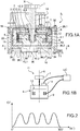
- the haptic interface I1 comprises an element 1 intended to be manipulated by a user and which will hereinafter be designated “button", this button is integral in rotation with a shaft 2 movable in rotation about the axis X, and a resistant force generation device 4 or magneto-rheological brake opposing the rotation of the shaft 2.
- the brake 4 comprises a fluid whose characteristics can be modified by means of a magnetic field and a system for generating a magnetic field 6 received in a housing 8.
- the fluid is, for example a magneto-rheological liquid.
- the assembly comprising the housing, the fluid and the system for generating a magnetic field forms a magneto-rheological brake.
- the housing 8 defines a sealed chamber 9 containing the magneto-rheological fluid. All or part of this room being subject to a field magnetic generated by the system 6.
- the housing 8 has a side wall 8.1, a lower bottom 8.2 and an upper bottom 8.3.
- the shaft 2 crosses the upper bottom 8.3, crosses the chamber 9 and crosses the lower bottom 8.2.
- the end 2.1 of the shaft 2, opposite to that carrying the button 1, is housed in the lower bottom of the housing 8 and is guided in rotation by means of a bearing 11 mounted in the lower bottom 8.2.
- the housing 8 defines a sealed chamber confining the magneto-rheological fluid.
- the brake 4 also includes an element 12 integral in rotation with the shaft 2 and housed in the sealed chamber 10. This element is capable of interacting with the magneto-rheological fluid, the rotation of the element 12 being more or less braked by the magneto-rheological fluid as a function of its apparent viscosity.
- the element 12 comprises two concentric side walls 12.1, 12.2 of circular cross section secured to a bottom 12.3, itself secured in rotation with the shaft.
- the element 12 may have only one side wall or more than two concentric side walls.
- the element 12 could be formed by a disc.
- the interaction element could include lights and / or protruding or recessed portions in order to increase the resistance to displacement.
- the lower bottom 8.2 of the housing 8 has a shape such that the interior volume of the sealed chamber 9 has a shape which corresponds to that of the interaction element 12, which makes it possible to reduce the amount of fluid required.
- a cylindrical element 13 of circular section integral with the housing is interposed between the two side walls 12.1, 12.2, this contributes to the shearing effect of the magneto-rheological fluid when the side walls 12.1 and 12.2 are rotated.
- the side walls 12.1, 12.2 of the element 12 can be made of magnetic or non-magnetic material.
- the system for generating a variable magnetic field 6 comprises a coil fixed to the housing and arranged inside the interaction element 12, and a current supply (not shown) controlled by a control unit according to the manipulation of the button and the pre-recorded patterns.
- the interface also includes a position sensor 14 which is, in the example shown, located outside the housing and partially secured to the shaft 2.
- the position sensor 14 makes it possible to measure the current position of the button, which is in the example shown the current angular position. It may for example be an incremental optical encoder.
- the haptic interface also comprises a frame 16 in which the housing 8 is disposed.
- the frame 16 comprises a first and a second end flange 18, 20 and a side wall 22 fixed to the two flanges 18, 20, the first flange 18 is crossed by the rotating shaft.
- the position sensor 14 is fixed to the first flange of the frame.
- the brake is intended to exert a resistant force opposing the movement of the element of interaction with the user.
- This resistant effort is determined from predefined haptic patterns as a function of the haptic rendering which it is desired to reproduce, these patterns are recorded in a database.
- a haptic pattern is therefore a set of braking force values to be applied to the button, ie a set of values defining the pattern, each value of the haptic pattern is associated with a given angular position of the button and with a direction of rotation of the button.
- Each braking force value corresponds to an apparent viscosity value which corresponds to a magnetic field value which corresponds to a current intensity supplying the system generating the magnetic field, for example a coil.
- the haptic interface includes a control unit UC intended to generate orders with said magnetic field generation system so that it applies the values of the pattern to be reproduced.
- a control unit UC intended to generate orders with said magnetic field generation system so that it applies the values of the pattern to be reproduced.
- control unit UC takes into account the value of the speed of actuation of the button, in addition to the direction of movement, to generate the order to the magnetic field generation system.
- Low speed is a speed whose value is less than or equal to a given threshold but is not zero.
- Fast speed is considered the maximum speed with which the button can be operated.
- the fast speed in the positive direction can be equal to or different from the fast speed in the negative direction.
- the actuation speed is advantageously approximated from the information provided by the position sensor, which makes it possible to offer a compact system.
- any other device other than the position sensor could be used to determine the speed of rotation.
- the position of the button, the actuation speed (variable SPEED) and the direction of actuation (variable DIRECTION) are determined from the information provided by the current position sensor.
- the DIRECTION variable can take the value +1 (direction of movement considered as positive), the value -1 (direction of movement considered as negative) or the value 0 when the speed is zero.
- Steps 102 and 104 can be simultaneous or sequential.
- a first step 200 it is checked whether the DIRECTION variable is equal to 0, if this is the case, in this example the control unit generates a command to the brake to apply no constraint to the button, ie no magnetic field is only applied to the fluid. The algorithm is finished. Alternatively, it could be decided to maintain the last magnetic field applied. This step could take place before step 102.
- SPEED being the absolute value of the variable SPEED
- V_MAX being the fixed value of the maximum actuation speed, this value is fixed for example at the usual maximum rotation speed with which a user usually actuates the button when he wishes to carry out rapid and coarse movements with the interface.
- V_MIN being the fixed value of the minimum actuation speed, this value is fixed for example at the usual minimum rotation speed with which a user usually actuates the button when he wishes to carry out slow and precise movements with the interface.
- V_MAX corresponds to the fast speed at which the MPR and MNR patterns are established without correction.
- V_MIN corresponds to the slow speed at which the MPL and MNL patterns are established without correction.
- the coefficient ALPHA is advantageously limited to 0 and 1 to avoid aberrant calculation results, in fact it may happen that, exceptionally, the button is actuated at a speed greater than the maximum speed which has been fixed, ie that the calculation of the ALPHA value provides a result greater than 1 since nothing mechanically limits the speed of actuation. In the same way it can happen that, in an exceptional way, the button is actuated at a speed lower than the minimum speed which was fixed, ie that the calculation of the value ALPHA provides a result lower than 0 since it is possible to choose for V_MIN a non-zero value.
- variable MOTIF_COURANT is applied to the brake.
- MOTIF_COURANT is calculated starting from a linear interpolation.
- a representation of this pattern can be seen as a function of the actuation speed in the case of actuation in the positive direction.
- any other interpolation for example a quadratic interpolation, can be used.
- the MOTIF_COURANT taking a value for a speed less than or equal to a threshold value and taking another value for a speed greater than the threshold value.
- the braking force is increased with the actuation speed if one chooses to take VPR> VPL (respectively VNR> VNL for the other actuation direction).
- the system for determining the intention of action of the user detects the torque exerted by the user on the button in the case of a rotary interface or the force applied by the user on the button in the case of a linear interface, and this before a movement of the button perceptible by the user and by the position sensor is applied to it.
- test body 26 of which we will detect the deformation caused by the torque applied by the user with force sensors.
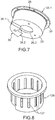
- the test body is shown alone on the figure 7 .
- the test body 26 is fixed by a longitudinal end 26.1 to the frame 16 and by the other longitudinal end 26.2 to the magneto-rheological brake, to the housing 8 in the example shown.
- the force sensors are in contact with the test body at its longitudinal end 26.2 secured to the housing 8.
- the test body 26 comprises a body of cylindrical shape with circular section closed by a bottom 28 at the longitudinal end 26.2.
- An annular flange 30 extends radially outward at the other longitudinal end 26.1.
- the internal diameter of the test body corresponds to the external diameter of the housing 8, increased by a clearance of operation.
- the bottom of the test body is disposed between the housing and the second flange 20 of the frame 16.
- test body is secured to the frame by means of at least one screw 32 passing through the flange 18 and the flange 30.
- the screws 32 also serve to connect the flange 18 to the side wall 28.
- the bottom 28 of the test body is fixed to the housing 8 by at least one screw 34.
- the test body 26 also includes an element 36 projecting from its longitudinal end 26.2 opposite to that in contact with the housing.
- the element 36 is received in a cavity 38 formed in the flange 20 of the frame.
- the projecting element 36 has the shape of an angular portion centered on the longitudinal axis.
- the angular portion 36 is delimited by two sides 36.1, 36.2.
- the cavity 38 has a shape corresponding to that of the angular portion 36 and is delimited by two faces 38.1 38.2 each facing a face 36.1, 36.2 of the angular portion 36.
- a force sensor 40.1 is mounted on the face 38.1 of the cavity in contact with the face 36.1 of the angular portion and a force sensor 40.2 is mounted on the face 38.2 of the cavity in contact with the face 36.2 of the angular portion 36.
- a point-type mechanical contact is ensured between each force sensor 40.1, 40.2 and the test body 26.
- the force sensors 40.1, 40.2 are advantageously mounted prestressed.
- the latter when a torque is applied to the button, the latter causes a torsional deformation of the test body 26 by means of the housing 8 itself in interaction with the fluid, itself in interaction with the element. interaction 12, itself linked to the shaft 2
- This deformation is detected by one or the other of the force sensors 40.1, 40.2 according to the direction of rotation of the button.
- the test body is for example made of plastic material, such as ABS.
- the material of the test body and its geometry can be determined according to the minimum and maximum torque applied, the sensitivity of the force sensors and the desired detection threshold.
- the deformation of the test body is such that it is not perceptible to the user. For example, it could be considered that a deformation of the test body of a few microns is not perceptible by the user.
- a torque sensor could be implemented directly on the housing 8 or on the rotary shaft, for this a torque sensor would be implemented.
- a torque sensor has a high cost and a large size compared to the force sensors.
- a torque sensor provides a precise and calibrated torque value while this information is not useful in the context of the invention.
- the force sensor is for example produced using piezoresistive elements assembled in the form of a Wheatstone bridge, they allow a sensitivity of the order of a few tens of mV per Newton with a sufficiently high stiffness to limit displacement to a few tens of microns at full charge.
- the force sensor (s) could be replaced by one or more deformation sensors formed, for example, by strain gauges directly applied to the test body to detect its deformation.
- test body 126 the general shape of which is identical to that of the test body 26, but also has longitudinal slots 127 in the side wall of the test body 126. From preferably, the lights 127 are distributed angularly in a regular manner.
- the test body has in this embodiment a greater ability to deformation. It is for example made of aluminum alloy.
- Lights inclined relative to the longitudinal axis and / or having a shape other than rectilinear for example a curved shape do not depart from the scope of the present invention. Furthermore, the lights do not necessarily have all the same dimensions.
- means may be provided for amplifying the deformation of the test body under an axial torsional stress while reducing the deformation of the test body for any other stress not relevant in the context of the invention, such as by example a radial stress which would be applied to the button in a parasitic way by the user.
- the detection sensitivity is thus improved and disturbances or false detections can be eliminated.
- test body Figures 1A , 6 to 8 increases the sensitivity of the measuring device by placing the sensors on the largest possible diameter.
- the walls 36.1 and 36.2 of the projecting element are arranged at 90 ° relative to each other.
- This positioning associated with a point contact at the level of the force sensors 40.1 and 40.2 makes it possible to decompose the stress of deformation of the test body and to favor the sensitivity to the forces according to two orthogonal components located in the plane of the frame 16.
- the sensitivity is greatly reduced for parasitic forces exerted perpendicular to the plane of the frame 16.
- a computational or algorithmic treatment on the components of the orthogonal forces measured by sensors 40.1 and 40.2, such as a calculation based on the difference in measurement between the two sensors weighted by the common measurement component of the two sensors in the case of a preferential assembly of the sensors with a load preload makes it possible to reduce to a certain extent the sensitivity to parasitic forces exerted parallel to the plane of the frame 16.
- the user turns the button around its axis in a first direction of rotation and brings it into an angular position defined as a stop.
- a magnetic field is applied to the magneto-rheological fluid so that its variation in apparent viscosity generates a torque at the level of the element for interaction with the fluid simulating a stop at the button in the first direction of rotation.
- test body 26 undergoes a torsional torque via the housing, itself in interaction with the fluid, itself in interaction with the element interaction 12, itself linked to tree 2
- This deformation is measured by the force sensor arranged downstream in the first direction of rotation. Knowing which of the force sensors is used makes it possible to know the direction in which the user intends to turn the button. Preferably, the measurements from the two force sensors assembled can be combined with a load preload to determine the direction in which the user intends to turn the button. Detection of a minimum torque makes it possible to confirm that the user actually intends to rotate the button. It follows that the user intends to keep the button in abutment. The magnetic field is maintained so as to oppose a force to the movement of the interaction element 12 via the viscous magneto-rheological fluid.
- the force sensor disposed upstream considering the first direction of rotation, which will be requested.
- this intention is confirmed by the detection of a minimum torque.
- the magnetic field is canceled, the apparent viscosity of the fluid decreases sharply, the interaction element can therefore rotate in the second direction without feeling any sticking effect.
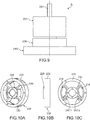
- an interface I2 comprising a frame 216, a brake 204, a test body 226 having the shape of a wheel and an element of interaction with the user 201, the element of interaction with the fluid not being visible.
- the wheel has a hub 228, an outer ring 232 and spokes 230 connecting the hub 228 to the outer ring 232.
- the hub 228 is secured to the interface box for example by screws axially passing through the hub 228 and the outer ring 232 is secured to the frame for example by screws axially passing through the outer ring.
- Two force sensors 240.1, 240.2 are disposed each bearing against a spoke 230 and arranged with respect to the spokes so that, when the test body 226 is biased in a direction of rotation, only one of the sensors is biased.
- the force sensors are fixed to the frame 216 and bear against a face with a radius 230.
- the force sensors could be assembled with a load preload, or, as was mentioned above , be replaced by elongation gauges arranged on the test body and detecting the deformation, for example of the rays under the effect of the torque. More generally, the force sensors can be replaced by deformation sensors.
- Means making it possible to apply mechanical stresses to the test body can advantageously be added, which makes it possible to reduce the number of force sensors by assembling the latter with a preload of charge.
- the data from these force or deformation sensors are processed by an electronic system to determine if the torque exerted by the user on the interface exceeds a predetermined threshold.
- the torque sign is also determined and makes it possible to know the direction in which the user intends to move the button.
- the device comprises a housing 308 in which is mounted an axis 302 movable axially along its axis X, the axis 302 being intended to carry an element of interaction with the user (not shown) at at least 1 'one of its longitudinal ends, means for generating a variable magnetic field 306 are arranged in the housing.
- the housing delimits a sealed chamber which contains magneto-rheological fluid and which is crossed by the axis 302. Joints 313 ensure a sealed sliding of the shaft in the chamber.
- the interface also includes a position sensor (not shown) for measuring the current longitudinal position of axis 302.
- the interface also includes means for detecting the intention of action of the user, these means then detect a translational force applied by the user on the axis before a movement of the axis perceptible by the user and by the position sensor applied to it.
- These means comprise a test body (not shown), the deformation of which is measured by one or more force or deformation sensors, the test body being fixed on the housing and on the frame (not shown). Yes the user intends to move the axis in the first direction of translation, the test body undergoes a shearing force via the housing, itself in interaction with the fluid, itself in interaction with the interaction element, itself linked to axis 302.
- the control electronics jointly use the information from the angular position sensor and the information from the force sensors to determine the resistive torque to be generated by the brake 4.
- the algorithm represented on the figure 12 is applied to determine the direction of rotation in which the knob is rotated or in which the user intends to rotate it.
- variable TORSION is an estimate of the torque. Knowledge of the precise torque value is not required. This estimate is obtained from the information provided by the force sensor which is requested by the test body in the embodiment of the Figures 1A , 6 to 8 .
- the estimation of the torque allows to know if it is higher or lower than threshold values taking into account the direction in which the torque is applied.
- the function for estimating the torsional moment applied by the user is calculated from information supplied by the force sensors, this function is the TORSION variable.
- step 404 it is checked whether the variable SPEED is zero, if it is not zero, the variable DIRECTION is assigned the sign of speed (step 406).
- a next step 408 it is checked whether the TORSION variable is greater than a threshold called "positive threshold", if this is the case, the variable DIRECTION is assigned the value +1 (step 410).
- variable DIRECTION takes the value zero.
- the system considers that no torque is applied to the button, it can for example be deduced therefrom that the user has released the button.
- fast speed is considered to be the maximum speed with which the button can be operated.
- the fast speed in the positive direction can be equal to or different from the fast speed in the negative direction.
- Steps 102 ′ and 104 can be simultaneous or sequential.
- a variant of the algorithm of the figure 5 represented on the figure 14 is then applied to effectively determine the value of the braking constraint to be applied, ie the magnetic field to be applied, and therefore the intensity of the current which will supply the magnetic field generation system.
- a first step 200 ′ it is checked whether the DIRECTION variable is equal to 0, if this is the case, the control unit generates a command to the brake to apply no constraint to the button, ie no magnetic field is applied to the fluid.
- the algorithm is finished.
- the coefficient ALPHA is advantageously limited to 0 and 1 to avoid calculation errors, in fact it may happen that, exceptionally, the button is actuated at a speed greater than the maximum speed which has been set, ie that ALPHA is greater than 1 since nothing mechanically limits the actuation speed.
- variable MOTIF_COURANT is applied to the brake.
- the MOTIF_COURANT could be calculated with any other interpolation, for example a quadratic interpolation, can be used. It can also be envisaged to use a threshold function.
- the haptic interface according to the invention is particularly suitable for application in motor vehicles, for example to form an on-board haptic interface assisting the car driver. It can allow the user to interact with different equipment or accessories of the vehicle such as GPS (Global Positioning System in English terminology or Global Positioning System), radio, air conditioning ...
- GPS Global Positioning System in English terminology or Global Positioning System
- radio Air conditioning ...
Description
La présente invention se rapporte à une interface haptique offrant une maîtrise du ressenti haptique améliorée.The present invention relates to a haptic interface offering improved control of haptic feeling.
Une interface haptique peut prendre la forme d'un bouton rotatif manipulé par un utilisateur, dans ce cas l'interface oppose un couple résistant à l'utilisateur en fonction de la position angulaire du bouton d'actionnement et du déplacement appliqué par l'utilisateur, permettant ainsi de définir des motifs haptiques qui seront ressentis par l'utilisateur lorsqu'il tourne le bouton.A haptic interface can take the form of a rotary button manipulated by a user, in this case the interface opposes a torque resistant to the user depending on the angular position of the actuation button and the displacement applied by the user. , thus making it possible to define haptic patterns which will be felt by the user when he turns the button.
Le couple résistant peut être transmis au bouton par l'intermédiaire d'un fluide magnéto-rhéologique dont la viscosité apparente est modifiée par l'application d'un champ magnétique afin de définir les motifs haptiques prédéfinis.The resisting torque can be transmitted to the button via a magneto-rheological fluid whose apparent viscosity is modified by the application of a magnetic field in order to define the predefined haptic patterns.
Certains motifs haptiques comportent de nombreuses variations du couple résistant dans une zone angulaire relativement étroite. Dans ce cas, on constate une diminution du ressenti haptique perçu par l'utilisateur lorsque la vitesse d'actionnement du bouton augmente.Certain haptic patterns include numerous variations of the resistive torque in a relatively narrow angular zone. In this case, there is a decrease in the haptic feeling perceived by the user when the speed of actuation of the button increases.
Le document
C'est par conséquent un but de la présente invention d'offrir une interface haptique offrant une maîtrise du ressenti haptique améliorée.It is therefore an object of the present invention to provide a haptic interface offering improved control of haptic feeling.
Le but précédemment énoncé est atteint par une interface haptique selon la revendication 1 ou la revendication 2.The previously stated object is achieved by a haptic interface according to
Grâce à l'invention, en appliquant un motif haptique qui est dépendant de la vitesse d'actionnement de l'élément d'interaction avec l'utilisateur, il est possible de moduler, par exemple d'accentuer le ressenti haptique en fonction de la vitesse d'actionnement de l'élément d'interaction avec l'utilisateur. Cette modulation peut porter sur des modifications d'amplitude ou de forme du motif. Ainsi en tenant compte de la vitesse d'actionnement dans la sélection de la valeur de motif haptique, la maîtrise du ressenti haptique est amélioré. On évite par exemple une diminution du ressenti haptique lorsque la vitesse d'actionnement est élevée.Thanks to the invention, by applying a haptic pattern which is dependent on the speed of actuation of the element of interaction with the user, it is possible to modulate, for example to accentuate the haptic feeling as a function of the actuation speed of the user interaction element. This modulation can relate to amplitude or shape modifications of the pattern. Thus by taking into account the actuation speed in the selection of the haptic pattern value, the control of the haptic feeling is improved. This prevents, for example, a decrease in haptic feeling when the actuation speed is high.
De manière particulièrement avantageuse, on utilise un motif à vitesse lente et un motif à vitesse rapide et on effectue une interpolation entre une valeur d'un motif à vitesse nulle ou faible et une valeur d'un motif à vitesse rapide pour la position mesurée.Particularly advantageously, a slow speed pattern and a fast speed pattern are used and an interpolation is carried out between a value of a pattern at zero or low speed and a value of a pattern at fast speed for the measured position.
Dans un mode de réalisation, on utilise un motif à vitesse lente et un motif à vitesse rapide et un seuil est fixé en dessous duquel on considère que la vitesse d'actionnement de l'élément d'interaction est lente et au-delà duquel on considère que la vitesse d'actionnement de l'élément d'interaction avec l'utilisateur est élevée, et on applique l'un ou l'autre des motifs suivant que la vitesse d'actionnement est considérée comme élevée ou comme faible.In one embodiment, a slow speed pattern and a fast speed pattern are used and a threshold is fixed below which the actuation speed of the interaction element is considered to be slow and beyond which one considers that the actuation speed of the user interaction element is high, and one or the other of the patterns is applied depending on whether the actuation speed is considered to be high or low.
En d'autres termes, pour chaque position courante on prévoit d'appliquer au moins deux valeurs de stimulus dont les intensités peuvent être différentes ou non afin de tenir compte de la vitesse d'actionnement de l'élément d'interaction avec l'utilisateur, alors que dans les interfaces haptiques de l'état de la technique une seule valeur de stimulus est appliquée pour chaque position courante quelle que soit la vitesse d'actionnement. Avantageusement une valeur de stimulus est déterminée pour chaque valeur de vitesse d'actionnement selon une loi ou un algorithme de calcul prédéterminé prenant la vitesse comme paramètre d'entrée.In other words, for each current position, provision is made to apply at least two stimulus values whose intensities may or may not be different in order to take account of the speed of actuation of the element of interaction with the user. , whereas in the haptic interfaces of the prior art only one stimulus value is applied for each current position regardless of the actuation speed. Advantageously, a stimulus value is determined for each actuation speed value according to a predetermined law or calculation algorithm taking the speed as an input parameter.
Selon une caractéristique additionnelle, il peut être prévu de mettre en œuvre un dispositif de détermination de l'intention d'action de l'utilisateur avant que le mouvement appliqué à l'élément d'interaction avec l'utilisateur ne devienne perceptible pour l'utilisateur et pour le capteur de mesure de position, afin de déterminer le sens de déplacement que l'utilisateur a l'intention d'appliquer à l'élément d'interaction avec l'utilisateur, ce qui permet d'améliorer encore le rendu haptique.According to an additional characteristic, provision may be made for implementing a device for determining the intention of action of the user before the movement applied to the user interaction element becomes noticeable to the user and to the position measurement sensor, in order to determine the direction of movement that the user intends to apply to the element of interaction with the user, which further improves the haptic rendering.
Par exemple, les moyens pour déterminer l'intention d'action de l'utilisateur sur l'élément d'interaction avec l'utilisateur comportent :
- des moyens pour détecter le couple exercé par un utilisateur sur l'élément d'interaction avec l'utilisateur, dans le cas d'un élément d'interaction avec l'utilisateur mobile en rotation, afin de connaître le sens du couple et si le couple est supérieur à une valeur donnée pour un sens donné, l'unité de commande commandant le système de génération dudit stimulus sur la base des informations obtenues sur le couple au moins lorsqu'une vitesse nulle ou faible de l'élément d'interaction avec l'utilisateur est détectée, ou
- des moyens pour détecter l'effort exercé par un utilisateur sur l'élément d'interaction avec l'utilisateur, dans le cas d'un élément d'interaction avec l'utilisateur mobile en translation, afin de connaître le sens de la force et si la force est supérieure à une valeur donnée pour un sens donné, l'unité de commande commandant le système de génération dudit stimulus sur la base des informations obtenues sur la force au moins lorsqu'une vitesse nulle ou faible de l'élément d'interaction avec l'utilisateur est détectée.
- means for detecting the torque exerted by a user on the element of interaction with the user, in the case of an element of interaction with the user mobile in rotation, in order to know the direction of the torque and if the torque is greater than a given value for a given direction, the control unit controlling the system for generating said stimulus on the basis of information obtained on the torque at least when a zero or low speed of the element of interaction with the user is detected, or
- means for detecting the force exerted by a user on the element of interaction with the user, in the case of an element of interaction with the user mobile in translation, in order to know the direction of the force and if the force is greater than a given value for a given direction, the control unit controlling the system for generating said stimulus on the basis of the information obtained on the force at least when a zero or low speed of the element of user interaction is detected.
Les moyens pour détecter le couple ou la force appliqué par l'utilisateur sur l'élément d'interaction avec l'utilisateur peuvent comporter au moins un capteur d'effort, préférentiellement monté en précontrainte ou au moins un capteur de la déformation provoquée par le couple ou la force à l'un des éléments de l'interface haptique.The means for detecting the torque or the force applied by the user to the element for interaction with the user may comprise at least one force sensor, preferably mounted in prestressing mode or at least one sensor for the deformation caused by the torque or force to one of the elements of the haptic interface.
L'interface haptique peut comporter un corps d'épreuve qui est disposé de sorte à être déformé par le couple ou la force appliqué par l'utilisateur sur l'élément d'interaction avec l'utilisateur, les moyens pour détecter le couple ou la force étant en contact avec ledit corps d'épreuve. De préférence, le corps d'épreuve est en un matériau tel que sa déformation n'est pas perceptible par l'utilisateur.The haptic interface may include a test body which is arranged so as to be deformed by the torque or the force applied by the user to the element of interaction with the user, the means for detecting the torque or the force being in contact with said test body. Preferably, the test body is made of a material such that its deformation is not perceptible to the user.
Avantageusement, les moyens générant les ordres mettent en œuvre une interpolation, par exemple une interpolation linéaire, entre une valeur de la première base de données et une valeur de la deuxième base de données ou entre une valeur de la troisième base de données et une valeur de la quatrième base de données.Advantageously, the means generating the orders implement an interpolation, for example a linear interpolation, between a value of the first database and a value of the second database or between a value of the third database and a value from the fourth database.
Par exemple, la deuxième vitesse donnée peut être fixée comme étant la vitesse d'actionnement maximale dans le premier sens d'actionnement et la quatrième vitesse donnée est fixée comme étant la vitesse d'actionnement maximale dans le deuxième sens d'actionnementFor example, the second given speed can be set as the maximum actuation speed in the first actuation direction and the given fourth speed is set as the maximum actuation speed in the second actuation direction
Dans un mode de réalisation avantageux, le fluide est un fluide magnéto-rhéologique, le stimulus étant un champ magnétique et les ordres générés sont des intensités de courant.In an advantageous embodiment, the fluid is a magneto-rheological fluid, the stimulus being a magnetic field and the orders generated are intensities of current.
Les moyens pour déterminer la vitesse d'actionnement peuvent par exemple calculer les dérivées des informations fournis par les moyens de détermination de la position courante.The means for determining the actuation speed can for example calculate the derivatives of the information supplied by the means for determining the current position.
Dans un exemple de réalisation, l'élément d'interaction avec l'utilisateur est mobile en rotation et est solidaire d'un arbre de rotation d'axe longitudinal duquel est solidaire en rotation l'élément d'interaction avec le fluide, les moyens de mesure de la position angulaire étant un capteur de position angulaire.In an exemplary embodiment, the element of interaction with the user is movable in rotation and is integral with a rotation shaft of longitudinal axis of which is integral in rotation with the element of interaction with the fluid, the means for measuring the angular position being an angular position sensor.
Dans un autre exemple de réalisation, l'élément d'interaction avec l'utilisateur est mobile en translation.In another exemplary embodiment, the element of interaction with the user is movable in translation.
La présente invention a également pour objet un procédé de commande d'une interface haptique selon l'invention, comportant les étapes:
- a) détermination de la position courante de l'élément d'interaction avec l'utilisateur,
- b) détermination de la vitesse de l'élément d'interaction avec l'utilisateur,
- c) détermination du sens d'actionnement,
- d) détermination, pour le sens d'actionnement déterminé, d'une valeur d'un motif haptique pour la vitesse d'actionnement déterminée,
- e) génération d'un ordre au système de génération dudit stimulus.
- a) determining the current position of the user interaction element,
- b) determining the speed of the user interaction element,
- c) determination of the direction of actuation,
- d) determination, for the determined actuation direction, of a value of a haptic pattern for the determined actuation speed,
- e) generation of an order to the system for generating said stimulus.
Lors de l'étape d), la valeur d'un motif haptique peut être déterminée à partir d'une première valeur d'un motif haptique pour une vitesse d'actionnement inférieure à une première valeur donnée et non nulle et d'une deuxième valeur d'un motif haptique pour une vitesse d'actionnement au moins égale à une deuxième valeur donnée.During step d), the value of a haptic pattern can be determined from a first value of a haptic pattern for an actuation speed lower than a first given value and not zero and a second value of a haptic pattern for an actuation speed at least equal to a second given value.
Par exemple, l'étape d) est une étape de calcul de ladite valeur d'un motif haptique pour la vitesse d'actionnement déterminée au moyen d'une fonction seuil, la valeur du motif pour la vitesse d'actionnement déterminée étant soit la première valeur d'un motif haptique pour une vitesse d'actionnement inférieure à une première valeur donnée, soit la deuxième valeur d'un motif haptique pour une vitesse d'actionnement au moins égale à une deuxième valeur donnée.For example, step d) is a step of calculating said value of a haptic pattern for the actuation speed determined by means of a threshold function, the value of the pattern for the determined actuation speed being either the first value of a haptic pattern for an actuation speed lower than a first given value, ie the second value of a haptic pattern for an actuation speed at least equal to a second given value.
De manière avantageuse, le procédé peut comporter l'étape préalable à l'étape d) de détermination de l'intention d'action de l'utilisateur sur l'élément d'interaction avec l'utilisateur. Lors de l'étape d), la valeur d'un motif haptique peut être déterminée à partir d'une première valeur d'un motif haptique pour une vitesse d'actionnement inférieure ou égale à une première valeur donnée éventuellement nulle et d'une deuxième valeur d'un motif haptique pour une vitesse d'actionnement au moins égale à une deuxième valeur donnée.Advantageously, the method may include the step prior to step d) of determining the intention of action of the user on the element of interaction with the user. During step d), the value of a haptic pattern can be determined from a first value of a haptic pattern for an actuation speed less than or equal to a first given value possibly zero and of a second value of a haptic pattern for an actuation speed at least equal to a second given value.
L'étape d) peut être une étape de calcul de ladite valeur d'un motif haptique pour la vitesse d'actionnement déterminée par interpolation, par exemple par interpolation linéaire.Step d) can be a step of calculating said value of a haptic pattern for the actuation speed determined by interpolation, for example by linear interpolation.
La présente invention sera mieux comprise sur la base de la description qui va suivre et des dessins en annexe sur lesquels:
- la
figure 1A est une vue en coupe d'un exemple de réalisation d'une interface haptique rotative pouvant être mise en œuvre dans la présente invention, - la
figure 1B est une représentation schématique d'une interface rotative selon l'invention, - la
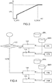
figure 2 une représentation graphique de la variation de la contrainte de freinage appliquée par un frein magnéto-rhéologique en fonction de la position angulaire d'un élément d'interaction avec l'utilisateur pour un motif dans un sens donné et pour une vitesse donnée, - la
figure 3 est une représentation graphique du niveau de freinage appliqué par le frein magnéto-rhéologique en fonction de la vitesse d'actionnement de l'élément d'interaction avec l'utilisateur, - les
figures 4 et5 représentent des exemples d'algorithmes de commande de l'interface haptique selon l'invention, - la
figure 6 est une vue en coupe transversale le long du plan A-A de l'interface de lafigure 1 , - la
figure 7 est une vue en perspective d'un exemple de réalisation d'un corps d'épreuve mis en œuvre dans l'interface de lafigure 6 , - la
figure 8 est une vue en perspective d'un autre exemple de réalisation d'un corps d'épreuve pouvant être mis en œuvre dans l'interface de lafigure 6 , - la
figure 9 est une vue de côté d'un autre exemple d'interface haptique, - les
figures 10A à 10C sont différentes vues du corps d'épreuve mis en œuvre dans l'interface de lafigure 9 , - la
figure 11 est une vue en éclaté d'un exemple d'interface haptique linéaire pouvant être mise en œuvre dans l'invention, - la
figure 12 représente un exemple d'algorithme de commande de l'interface haptique selon l'invention, - les
figures 13 et14 représentent des variantes de l'algorithme desfigures 4 et5 respectivement, tenant compte de la connaissance de l'intention d'action de l'utilisateur.
- the
figure 1A is a sectional view of an exemplary embodiment of a rotary haptic interface which can be implemented in the present invention, - the
figure 1B is a schematic representation of a rotary interface according to the invention, - the
figure 2 a graphic representation of the variation of the braking stress applied by a magneto-rheological brake as a function of the angular position of an element of interaction with the user for a pattern in a given direction and for a given speed, - the
figure 3 is a graphic representation of the braking level applied by the magneto-rheological brake as a function of the speed of actuation of the element of interaction with the user, - the
figures 4 and5 represent examples of haptic interface control algorithms according to the invention, - the
figure 6 is a cross-sectional view along the plane AA of the interface of thefigure 1 , - the
figure 7 is a perspective view of an exemplary embodiment of a test body implemented in the interface of thefigure 6 , - the
figure 8 is a perspective view of another embodiment of a test body that can be implemented in the interface of thefigure 6 , - the
figure 9 is a side view of another example of a haptic interface, - the
Figures 10A to 10C are different views of the test body implemented in the interface of thefigure 9 , - the
figure 11 is an exploded view of an example of a linear haptic interface that can be implemented in the invention, - the
figure 12 represents an example of an algorithm for controlling the haptic interface according to the invention, - the
figures 13 and14 represent variants of the algorithm offigures 4 and5 respectively, taking into account the knowledge of the user's intended action.
Dans la description qui va suivre, l'exemple d'une interface haptique à bouton rotatif va être décrit en détail, mais il sera compris que l'invention s'applique également à une interface haptique à déplacement linéaire de type curseur. En outre, l'interface décrite met en œuvre un fluide magnéto-rhéologique, i.e. dont la viscosité apparente varie en fonction du champ magnétique appliqué, mais la mise en œuvre d'un fluide électro-rhéologique, i.e. un fluide dont la viscosité apparente dépend du champ électrique appliqué, ne sort pas du cadre de la présente invention.In the description which follows, the example of a haptic interface with a rotary button will be described in detail, but it will be understood that the invention also applies to a haptic interface with linear displacement of the cursor type. In addition, the interface described implements a magneto-rheological fluid, ie whose apparent viscosity varies as a function of the magnetic field applied, but the implementation of an electro-rheological fluid, ie a fluid whose apparent viscosity depends of the applied electric field, does not depart from the scope of the present invention.
Sur la
L'interface haptique I1 comporte un élément 1 destiné à être manipulé par un utilisateur et qui sera désigné par la suite « bouton », ce bouton est solidaire en rotation d'un arbre 2 mobile en rotation autour de l'axe X, et un dispositif de génération d'effort résistant 4 ou frein magnéto-rhéologique s'opposant à la rotation de l'arbre 2.The haptic interface I1 comprises an
Le frein 4 comporte un fluide dont on peut modifier les caractéristiques au moyen d'un champ magnétique et un système de génération d'un champ magnétique 6 reçus dans un boîtier 8. Le fluide est, par exemple un liquide magnéto-rhéologique. L'ensemble comprenant le boîtier, le fluide et le système de génération d'un champ magnétique forme un frein magnéto-rhéologique.The
Le boîtier 8 délimite une chambre étanche 9 contenant le fluide magnéto-rhéologique. Tout ou partie de cette chambre étant soumise à un champ magnétique généré par le système 6. Le boîtier 8 comporte une paroi latérale 8.1, un fond inférieur 8.2 et un fond supérieur 8.3.The
L'arbre 2 traverse le fond supérieur 8.3, traverse la chambre 9 et traverse le fond inférieur 8.2. L'extrémité 2.1 de l'arbre 2, opposée à celle portant le bouton 1, est logée dans le fond inférieur du boîtier 8 et est guidée en rotation au moyen d'un roulement 11 monté dans le fond inférieur 8.2. Des joints 13, par exemple des joints toriques, assurent l'étanchéité entre l'arbre et les fond inférieur et supérieur.The
Le boîtier 8 délimite une chambre étanche confinant le fluide magnéto-rhéologique.The
Le frein 4 comporte également un élément 12 solidaire en rotation de l'arbre 2 et logé dans la chambre étanche 10. Cet élément est apte à interagir avec le fluide magnéto-rhéologique, la rotation de l'élément 12 étant plus au moins freinée par le fluide magnéto-rhéologique en fonction de sa viscosité apparente.The
Dans l'exemple représenté, l'élément 12 comporte deux parois latérales concentriques 12.1, 12.2 de section transversale circulaire solidaire d'un fond 12.3, lui-même solidarisé en rotation avec l'arbre.In the example shown, the
En variante, l'élément 12 peut ne comporter qu'une paroi latérale ou plus de deux parois latérales concentriques. En variante encore, l'élément 12 pourrait être formé par un disque. Par ailleurs, l'élément d'interaction pourrait comporter des lumières et/ou des portions en saillie ou en creux afin d'augmenter la résistance au déplacement.Alternatively, the
Dans l'exemple représenté, le fond inférieur 8.2 du boîtier 8 a une forme telle que le volume intérieur de la chambre étanche 9 a une forme qui correspond à celle de l'élément d'interaction 12, ce qui permet de réduire la quantité de fluide nécessaire. Dans l'exemple représenté, un élément cylindrique 13 à section circulaire solidaire du boîtier est interposé entre les deux parois latérales 12.1, 12.2, celui-ci contribue à l'effet de cisaillement du fluide magnéto-rhéologique lorsque les parois latérales 12.1 et 12.2 sont mises en rotation.In the example shown, the lower bottom 8.2 of the
Les parois latérales 12.1, 12.2 de l'élément 12 peuvent être en matériau magnétique ou amagnétique.The side walls 12.1, 12.2 of the
Dans l'exemple représenté, le système de génération d'un champ magnétique variable 6 comporte une bobine fixée sur le boîtier et disposée à l'intérieur de l'élément d'interaction 12, et une alimentation en courant (non représentée) commandée par une unité de commande en fonction de la manipulation du bouton et des motifs préenregistrés.In the example shown, the system for generating a variable
L'interface comporte également un capteur de position 14 qui est, dans l'exemple représenté, situé à l'extérieur du boîtier et en partie solidaire de l'arbre 2. Le capteur de position 14 permet de mesurer la position courante du bouton, qui est dans l'exemple représenté la position angulaire courante. Il peut s'agir par exemple d'un codeur optique incrémental.The interface also includes a
L'interface haptique comporte également un bâti 16 dans lequel est disposé le boîtier 8. Le bâti 16 comporte un premier et un deuxième flasque d'extrémité 18, 20 et une paroi latérale 22 fixée aux deux flasques 18, 20, le premier flasque 18 est traversé par l'arbre rotatif. Le capteur de position 14 est fixé sur le premier flasque du bâti.The haptic interface also comprises a
Le frein est destiné à exercer un effort résistant s'opposant au déplacement de l'élément d'interaction avec l'utilisateur. Cet effort résistant est déterminé à partir de motifs haptiques prédéfinis en fonction du rendu haptique que l'on souhaite reproduire, ces motifs sont enregistrés dans une base de données.The brake is intended to exert a resistant force opposing the movement of the element of interaction with the user. This resistant effort is determined from predefined haptic patterns as a function of the haptic rendering which it is desired to reproduce, these patterns are recorded in a database.
Un motif est défini par un effort de freinage à appliquer en fonction des données suivantes:
- la position angulaire courante du bouton,
- le sens de rotation courant du bouton,
- la vitesse de rotation du bouton.
- the current angular position of the button,
- the current direction of rotation of the button,
- the speed of rotation of the button.
Un motif haptique est donc un ensemble de valeurs d'effort de freinage à appliquer au bouton, i.e. un ensemble de valeurs définissant le motif, chaque valeur du motif haptique est associée à une position angulaire donnée du bouton et à un sens de rotation du bouton. Chaque valeur d'effort de freinage correspond à une valeur de viscosité apparente qui correspond à une valeur de champ magnétique qui correspond à une intensité de courant alimentant le système générant le champ magnétique, par exemple une bobine.A haptic pattern is therefore a set of braking force values to be applied to the button, ie a set of values defining the pattern, each value of the haptic pattern is associated with a given angular position of the button and with a direction of rotation of the button. . Each braking force value corresponds to an apparent viscosity value which corresponds to a magnetic field value which corresponds to a current intensity supplying the system generating the magnetic field, for example a coil.
Il est bien entendu que la même valeur du motif peut être affectée pour des positions angulaires différentes, ou plusieurs positions linéaires différentes dans le cas d'une interface linéaire.It is understood that the same value of the pattern can be assigned for different angular positions, or several different linear positions in the case of a linear interface.
Sur la
L'interface haptique comporte une unité de commande UC destinée à générer des ordres audit système de génération de champ magnétique de sorte qu'il applique les valeurs du motif à reproduire. Sur la
Selon l'invention, l'unité de commande UC prend en compte la valeur de la vitesse d'actionnement du bouton, en plus du sens de déplacement, pour générer l'ordre au système de génération de champ magnétique.According to the invention, the control unit UC takes into account the value of the speed of actuation of the button, in addition to the direction of movement, to generate the order to the magnetic field generation system.
Pour cela on définit quatre motifs:
- un motif MPL défini pour le sens d'actionnement considéré comme positif du bouton et pour une vitesse de rotation faible;
- un motif MPR pour le sens positif d'actionnement du bouton et pour une vitesse de rotation rapide;
- un motif MNL défini pour le sens d'actionnement considéré comme négatif du bouton et pour une vitesse de rotation faible;
- un motif MNR pour le sens d'actionnement du bouton négatif et pour une vitesse de rotation rapide.
- an MPL pattern defined for the direction of actuation considered positive of the button and for a low speed of rotation;
- an MPR pattern for the positive direction of actuation of the button and for a fast rotation speed;
- an MNL pattern defined for the direction of actuation considered as negative of the button and for a low rotation speed;
- an MNR pattern for the direction of actuation of the negative button and for a fast rotation speed.
La vitesse faible est une vitesse dont la valeur est inférieure ou égale à un seuil donné mais n'est pas nulle.Low speed is a speed whose value is less than or equal to a given threshold but is not zero.
La vitesse rapide est considérée comme la vitesse maximale avec laquelle le bouton peut être actionné. La vitesse rapide dans le sens positif peut être égale ou différente de la vitesse rapide dans le sens négatif.Fast speed is considered the maximum speed with which the button can be operated. The fast speed in the positive direction can be equal to or different from the fast speed in the negative direction.
La vitesse d'actionnement est avantageusement approximée à partir des informations fournies par le capteur de position, ce qui permet d'offrir un système compact. Néanmoins on pourrait utiliser tout autre dispositif distinct du capteur de position pour déterminer la vitesse de rotation.The actuation speed is advantageously approximated from the information provided by the position sensor, which makes it possible to offer a compact system. However, any other device other than the position sensor could be used to determine the speed of rotation.
Sur la
Lors d'une première étape 100, on détermine la position du bouton, la vitesse d'actionnement (variable VITESSE) et le sens d'actionnement (variable DIRECTION) à partir de l'information fournie par le capteur de position courante. La variable DIRECTION peut prendre la valeur +1 (sens de déplacement considéré comme positif), la valeur -1 (sens de déplacement considéré comme négatif) ou la valeur 0 lorsque la vitesse est nulle.During a
Si la variable DIRECTION est égale à +1, alors :
- on va chercher dans la base de données de motif positif à vitesse lente BPL la valeur de motif VPL (étape 102), et
- on va chercher dans la base de données de motif positif à vitesse rapide BPR la valeur de motif VPR (étape 104).
- we will search the low-speed positive pattern database BPL for the pattern value VPL (step 102), and
- we will look in the database of positive pattern at high speed BPR for the value of VPR pattern (step 104).
Les étapes 102 et 104 peuvent être simultanées ou séquentielles.
Sinon, i.e. si la variable DIRECTION est égale à -1 ou O, alors :
- on va chercher dans la base de données de motif négatif à vitesse lente BNL la valeur de motif VNL (étape 106), et
- on va chercher dans la base de données de motif négatif à vitesse rapide BNR la valeur de motif VNR (étape 108).
- we will search the low-speed negative pattern database BNL for the pattern value VNL (step 106), and
- the VNR pattern value will be searched in the fast-speed negative pattern database BNR (step 108).
A la fin du déroulement du premier algorithme, on dispose de deux valeurs de motif soit VPL et VPR, soit VNL et VNR.At the end of the course of the first algorithm, there are two pattern values either VPL and VPR, or VNL and VNR.
Sur la figue 5, on peut voir un exemple avantageux d'un deuxième algorithme permettant de déterminer la contrainte de freinage ou l'intensité du courant, celles-ci étant considérées comme proportionnelles, à appliquer au système de génération de champ magnétique.In Fig. 5, we can see an advantageous example of a second algorithm for determining the braking stress or the intensity of the current, these being considered proportional, to be applied to the magnetic field generation system.
Lors d'une première étape 200, on vérifie si la variable DIRECTION est égale à 0, si c'est le cas, dans cet exemple l'unité de commande génère un ordre au frein de n'appliquer aucune contrainte au bouton, i.e. aucun champ magnétique n'est appliqué au fluide. L'algorithme est terminé. Alternativement, il pourrait être décidé de maintenir le dernier champ magnétique appliqué. Cette étape pourrait avoir lieu avant l'étape 102.During a
Si la variable DIRECTION est différente de 0, i.e. si elle est égale à +1 ou - 1 alors, lors d'une étape suivante 202, on calcule le coefficient ALPHA qui est égal à : (abs(VITESSE) - V_MIN)/(V_MAX - V-MIN).If the DIRECTION variable is different from 0, ie if it is equal to +1 or - 1 then, during a
abs(VITESSE) étant la valeur absolue de la variable VITESSE,
V_MAX étant la valeur fixée de la vitesse maximale d'actionnement, cette valeur est fixée par exemple à la vitesse de rotation maximale usuelle avec laquelle un utilisateur actionne habituellement le bouton lorsqu'il souhaite réaliser des déplacements rapides et grossiers avec l'interface.abs (SPEED) being the absolute value of the variable SPEED,
V_MAX being the fixed value of the maximum actuation speed, this value is fixed for example at the usual maximum rotation speed with which a user usually actuates the button when he wishes to carry out rapid and coarse movements with the interface.
V_MIN étant la valeur fixée de la vitesse minimale d'actionnement, cette valeur est fixée par exemple à la vitesse de rotation minimale usuelle avec laquelle un utilisateur actionne habituellement le bouton lorsqu'il souhaite réaliser des déplacements lents et précis avec l'interface.V_MIN being the fixed value of the minimum actuation speed, this value is fixed for example at the usual minimum rotation speed with which a user usually actuates the button when he wishes to carry out slow and precise movements with the interface.
V_MAX correspond à la vitesse rapide à laquelle les motifs MPR et MNR sont établis sans correction.V_MAX corresponds to the fast speed at which the MPR and MNR patterns are established without correction.
V_MIN correspond à la vitesse lente à laquelle les motifs MPL et MNL sont établis sans correction.V_MIN corresponds to the slow speed at which the MPL and MNL patterns are established without correction.
Lors d'une étape suivante 204, on limite avantageusement le coefficient ALPHA ente 0 et 1 pour éviter des résultats de calcul aberrants, en effet il peut arriver que, de manière exceptionnelle, le bouton soit actionné à une vitesse supérieure à la vitesse maximale qui a été fixée, i.e. que le calcul de la valeur ALPHA fournisse un résultat supérieur à 1 puisque rien ne limite mécaniquement la vitesse d'actionnement. De même il peut arriver que, de manière exceptionnelle, le bouton soit actionné à une vitesse inférieure à la vitesse minimale qui a été fixée, i.e. que le calcul de la valeur ALPHA fournisse un résultat inférieur à 0 puisque il est possible de choisir pour V_MIN une valeur non nulle.During a
Lors d'une étape suivante 206, on calcule la variable MOTIF_COURANT à partir d'une interpolation linéaire sur la base des valeurs de motifs sélectionnées par le premier algorithme.
- ∘ MOTIF_COURANT = (1-ALPHA)∗ VPL + ALPHA∗ VPR si le sens d'actionnement est positif ou
- ∘ MOTIF_COURANT = (1-ALPHA)∗ VNL + ALPHA∗ VNR si le sens d'actionnement est négatif.
- ∘ MOTIF_COURANT = (1-ALPHA) ∗ VPL + ALPHA ∗ VPR if the direction of actuation is positive or
- ∘ MOTIF_COURANT = (1-ALPHA) ∗ VNL + ALPHA ∗ VNR if the direction of actuation is negative.
Lors d'une étape suivante 208, on applique la variable MOTIF_COURANT au frein.During a following
Dans l'algorithme de la
Toute autre interpolation, par exemple une interpolation quadratique, peut être utilisée.Any other interpolation, for example a quadratic interpolation, can be used.
Il peut également être envisagé d'utiliser une fonction seuil, le MOTIF_COURANT prenant une valeur pour une vitesse inférieure ou égale à une valeur seuil et prenant une autre valeur pour une vitesse supérieure à la valeur seuil.It can also be envisaged to use a threshold function, the MOTIF_COURANT taking a value for a speed less than or equal to a threshold value and taking another value for a speed greater than the threshold value.
Dans l'algorithme de la
Il peut au contraire être prévu que l'effort de freinage diminue alors que la vitesse d'actionnement augmente ou encore que la relation entre le MOTIF COURANT et la vitesse ne soit pas monotone.It can on the contrary be expected that the braking force decreases while the actuation speed increases or that the relationship between the CURRENT PATTERN and the speed is not monotonous.
Les algorithmes décrits ci-dessus s'appliquent complètement à une interface haptique linéaire, le capteur de position déterminerait alors des positions longitudinales et non des positions angulaires.The algorithms described above apply completely to a linear haptic interface, the position sensor would then determine longitudinal positions and not angular positions.
Dans un mode de réalisation particulièrement avantageux, il est prévu de mettre en œuvre un système de détermination de l'intention d'action de l'utilisateur afin d'améliorer encore le rendu haptique général de l'interface.In a particularly advantageous embodiment, provision is made to implement a system for determining the intention of action of the user in order to further improve the general haptic rendering of the interface.
Le système de détermination de l'intention d'action de l'utilisateur détecte le couple exercé par l'utilisateur sur le bouton dans le cas d'une interface rotative ou la force appliquée par l'utilisateur sur le bouton dans le cas d'une interface linéaire, et ceci avant qu'un déplacement du bouton perceptible par l'utilisateur et par le capteur de position lui soit appliqué.The system for determining the intention of action of the user detects the torque exerted by the user on the button in the case of a rotary interface or the force applied by the user on the button in the case of a linear interface, and this before a movement of the button perceptible by the user and by the position sensor is applied to it.
Dans l'exemple représenté sur les
Dans l'exemple représenté sur les
Le diamètre intérieur du corps d'épreuve correspond au diamètre extérieur du boîtier 8, augmenté d'un jeu de fonctionnement. Le fond du corps d'épreuve est disposé entre le boîtier et le deuxième flasque 20 du bâti 16.The internal diameter of the test body corresponds to the external diameter of the
Le corps d'épreuve est solidarisé au bâti au moyen d'au moins une vis 32 traversant le flasque 18 et la collerette 30. Dans l'exemple représenté, les vis 32 servent également à lier le flasque 18 à la paroi latérale 28.The test body is secured to the frame by means of at least one
Le fond 28 du corps d'épreuve est fixé au boîtier 8 par au moins une vis 34.The bottom 28 of the test body is fixed to the
Le corps d'épreuve 26 comporte également un élément 36 en saillie de son extrémité longitudinale 26.2 opposée à celle en contact avec le boîtier. L'élément 36 est reçu dans une cavité 38 ménagée dans le flasque 20 du bâti.The
Dans l'exemple représenté, l'élément en saillie 36 a la forme d'une portion angulaire centrée sur l'axe longitudinal. La portion angulaire 36 est délimitée par deux faces 36.1, 36.2. La cavité 38 présente une forme correspondant à celle de la portion angulaire 36 et est délimitée par deux faces 38.1 38.2 chacune en regard d'une face 36.1, 36.2 de la portion angulaire 36. Un capteur d'effort 40.1 est monté sur la face 38.1 de la cavité en contact avec la face 36.1 de la portion angulaire et un capteur d'effort 40.2 est monté sur la face 38.2 de la cavité en contact avec la face 36.2 de la portion angulaire 36. Un contact mécanique de type ponctuel est assuré entre chaque capteur d'effort 40.1, 40.2 et le corps d'épreuve 26. Les capteurs d'effort 40.1, 40.2 sont avantageusement montés précontraints.In the example shown, the projecting
Ainsi, lorsqu'un couple est appliqué au bouton, celui-ci provoque une déformation par torsion du corps d'épreuve 26 par l'intermédiaire du boitier 8 lui-même en interaction avec le fluide, lui-même en interaction avec l'élément d'interaction 12, lui-même lié à l'arbre 2 Cette déformation est détectée par l'un ou l'autre des capteurs d'effort 40.1, 40.2 suivant le sens de rotation du bouton.Thus, when a torque is applied to the button, the latter causes a torsional deformation of the
Le corps d'épreuve est par exemple en matériau plastique, tel que l'ABS.The test body is for example made of plastic material, such as ABS.
Le matériau du corps d'épreuve et sa géométrie peuvent être déterminés en fonction du couple minimal et du couple maximal appliqués, de la sensibilité des capteurs d'effort et du seuil de détection souhaité. En outre, la déformation du corps d'épreuve est telle qu'elle n'est pas perceptible par l'utilisateur. Par exemple, on put considérer qu'une déformation du corps d'épreuve de quelques microns n'est pas perceptible par l'utilisateur.The material of the test body and its geometry can be determined according to the minimum and maximum torque applied, the sensitivity of the force sensors and the desired detection threshold. In addition, the deformation of the test body is such that it is not perceptible to the user. For example, it could be considered that a deformation of the test body of a few microns is not perceptible by the user.
Alternativement, on pourrait mesurer les efforts directement sur le boîtier 8 ou sur l'arbre rotatif, pour cela un capteur de couple serait mis en œuvre. Cependant un capteur de couple a un coût élevé et un encombrement important par rapport aux capteurs de force. Par ailleurs, un capteur de couple fournit une valeur du couple précise et calibrée alors que cette information n'est pas utile dans le cadre de l'invention.Alternatively, the forces could be measured directly on the
Le capteur d'effort est par exemple réalisé à l'aide d'éléments piézorésistifs assemblés sous la forme d'un pont de Wheatstone, ils permettent une sensibilité de l'ordre de quelques dizaines de mV par Newton avec une raideur suffisamment élevée pour limiter le déplacement à quelques dizaines de microns à pleine charge. En variante, le ou les capteurs d'effort pourraient être remplacés par un ou des capteurs de déformation formés, par exemple, par des jauges de contrainte directement appliquées sur le corps d'épreuve pour détecter sa déformation.The force sensor is for example produced using piezoresistive elements assembled in the form of a Wheatstone bridge, they allow a sensitivity of the order of a few tens of mV per Newton with a sufficiently high stiffness to limit displacement to a few tens of microns at full charge. As a variant, the force sensor (s) could be replaced by one or more deformation sensors formed, for example, by strain gauges directly applied to the test body to detect its deformation.
Sur la
Des lumières inclinées par rapport à l'axe longitudinal et/ou ayant une forme autre que rectiligne par exemple une forme courbée ne sortent pas du cadre de la présente invention. Par ailleurs les lumières n'ont pas nécessairement toutes les mêmes dimensions.Lights inclined relative to the longitudinal axis and / or having a shape other than rectilinear for example a curved shape do not depart from the scope of the present invention. Furthermore, the lights do not necessarily have all the same dimensions.
De manière avantageuse, on peut prévoir des moyens pour amplifier la déformation du corps d'épreuve sous une contrainte de torsion axiale tout en réduisant la déformation du corps d'épreuve pour toute autre contrainte non pertinente dans le cadre de l'invention, comme par exemple une contrainte radiale qui serait appliquée au bouton de manière parasite par l'utilisateur. La sensibilité de la détection est ainsi améliorée et les perturbations ou fausses détections peuvent être éliminées.Advantageously, means may be provided for amplifying the deformation of the test body under an axial torsional stress while reducing the deformation of the test body for any other stress not relevant in the context of the invention, such as by example a radial stress which would be applied to the button in a parasitic way by the user. The detection sensitivity is thus improved and disturbances or false detections can be eliminated.
L'exemple de corps d'épreuve des
Dans l'exemple représenté et de manière avantageuse, les parois 36.1 et 36.2 de l'élément en saillie sont disposées à 90° l'une par rapport à l'autre. Ce positionnement associé à un contact ponctuel au niveau des capteurs d'effort 40.1 et 40.2 permet de décomposer la contrainte de déformation du corps d'épreuve et de privilégier la sensibilité aux efforts selon deux composantes orthogonales situées dans le plan du bâti 16. Ainsi par exemple, la sensibilité est fortement réduite pour des efforts parasites exercés perpendiculairement au plan du bâti 16. De plus, un traitement calculatoire ou algorithmique sur les composantes des forces orthogonales mesurées par les capteurs 40.1 et 40.2, comme par exemple un calcul basé sur la différence de mesure entre les deux capteurs pondéré par la composante commune de mesure des deux capteurs dans le cas d'un assemblage préférentiel des capteurs avec une précontrainte de charge, permet de réduire dans une certaine mesure la sensibilité aux efforts parasites exercés parallèlement au plan du bâti 16.In the example shown and advantageously, the walls 36.1 and 36.2 of the projecting element are arranged at 90 ° relative to each other. This positioning associated with a point contact at the level of the force sensors 40.1 and 40.2 makes it possible to decompose the stress of deformation of the test body and to favor the sensitivity to the forces according to two orthogonal components located in the plane of the
Un exemple de fonctionnement du dispositif dans lequel l'intention d'action de l'utilisateur est déterminée va maintenant être décrit.An example of operation of the device in which the intention of action of the user is determined will now be described.
L'utilisateur tourne le bouton autour de son axe dans un premier sens de rotation et l'amène dans une position angulaire définie comme une butée. Un champ magnétique est appliqué au fluide magnéto-rhéologique de sorte que sa variation de viscosité apparente génère un couple au niveau de l'élément d'interaction avec le fluide simulant une butée au niveau du bouton dans le premier sens de rotation.The user turns the button around its axis in a first direction of rotation and brings it into an angular position defined as a stop. A magnetic field is applied to the magneto-rheological fluid so that its variation in apparent viscosity generates a torque at the level of the element for interaction with the fluid simulating a stop at the button in the first direction of rotation.
Si l'utilisateur maintient son effort sur le bouton dans le premier sens de rotation, le corps d'épreuve 26 subit un couple de torsion via le boîtier, lui-même en interaction avec le fluide, lui-même en interaction avec l'élément d'interaction 12, lui-même lié à l'arbre 2If the user maintains his effort on the button in the first direction of rotation, the
Cette déformation est mesurée par le capteur de force disposé en aval dans le premier sens de rotation. Le fait de savoir lequel des capteurs de force est sollicité permet de connaître le sens dans lequel l'utilisateur a l'intention de tourner le bouton. De manière préférentielle, on peut combiner les mesures issues des deux capteurs de force assemblés avec une précontrainte de charge pour déterminer le sens dans lequel l'utilisateur a l'intention de tourner le bouton. La détection d'un couple minimal permet de confirmer que l'utilisateur a effectivement l'intention de faire pivoter le bouton. Il en est déduit que l'utilisateur a l'intention de maintenir le bouton en butée. Le champ magnétique est maintenu de sorte à opposer un effort au mouvement de l'élément d'interaction 12 via le fluide magnéto-rhéologique visqueux.This deformation is measured by the force sensor arranged downstream in the first direction of rotation. Knowing which of the force sensors is used makes it possible to know the direction in which the user intends to turn the button. Preferably, the measurements from the two force sensors assembled can be combined with a load preload to determine the direction in which the user intends to turn the button. Detection of a minimum torque makes it possible to confirm that the user actually intends to rotate the button. It follows that the user intends to keep the button in abutment. The magnetic field is maintained so as to oppose a force to the movement of the
Si l'utilisateur a l'intention de faire pivoter le bouton dans un deuxième sens opposé au premier sens, c'est le capteur d'effort disposé en amont en considérant le premier sens de rotation, qui va être sollicité. De manière préférentielle, on peut combiner les mesures issues des deux capteurs de force assemblés avec une précontrainte de charge pour déterminer le nouveau sens dans lequel l'utilisateur a l'intention de tourner le bouton. On en déduit l'intention de l'utilisateur, cette intention est confirmée par la détection d'un couple minimal. Dans ce cas, le champ magnétique est annulé, la viscosité apparente du fluide diminue fortement, l'élément d'interaction peut donc tourner dans le deuxième sens sans ressentir d'effet de collage. On peut ainsi reproduire grâce à l'invention le fonctionnement d'une roue libre.If the user intends to rotate the button in a second direction opposite to the first direction, it is the force sensor disposed upstream considering the first direction of rotation, which will be requested. Preferably, it is possible to combine the measurements from the two force sensors assembled with a load preload to determine the new direction in which the user intends to turn the button. We deduce the intention of the user, this intention is confirmed by the detection of a minimum torque. In this case, the magnetic field is canceled, the apparent viscosity of the fluid decreases sharply, the interaction element can therefore rotate in the second direction without feeling any sticking effect. We can thus reproduce thanks to the invention the operation of a freewheel.
Sur les
La roue comporte un moyeu 228, un anneau extérieur 232 et des rayons 230 reliant le moyeu 228 à l'anneau extérieur 232.The wheel has a
Dans cet exemple, le moyeu 228 est solidarisé au boîtier de l'interface par exemple par des vis traversant axialement le moyeu 228 et l'anneau extérieur 232 est solidarisé au bâti par exemple par des vis traversant axialement l'anneau extérieur.In this example, the
Deux capteurs d'effort 240.1, 240.2 sont disposés en appui chacun contre un rayon 230 et disposés par rapport aux rayons de sorte que, lorsque le corps d'épreuve 226 est sollicité dans un sens de rotation, un seul des capteurs est sollicité. Les capteurs d'efforts sont fixés sur le bâti 216 et en appui contre une face d'un rayon 230. En variante, les capteurs d'effort pourraient être assemblés avec une précontrainte de charge, ou, comme cela a été mentionné ci-dessus, être remplacés par des jauges d'élongation disposées sur le corps d'épreuve et détectant la déformation par exemple des rayons sous l'effet du couple de torsion. Plus généralement les capteurs d'effort peuvent être remplacés par des capteurs de déformation.Two force sensors 240.1, 240.2 are disposed each bearing against a
Le fonctionnement de ce dispositif est similaire à celui du dispositif de la
Des moyens permettant d'appliquer des contraintes mécaniques au corps d'épreuve, comme de moyens de guidage en rotation ou en translation, peuvent avantageusement être ajoutés, ce qui permet de réduire le nombre de capteurs de force en assemblant ce dernier avec une précontrainte de charge.Means making it possible to apply mechanical stresses to the test body, such as means for guiding in rotation or in translation, can advantageously be added, which makes it possible to reduce the number of force sensors by assembling the latter with a preload of charge.
Les données issues de ces capteurs de force ou de déformation sont traitées par un système électronique afin de déterminer si le couple exercé par l'utilisateur sur l'interface dépasse un seuil prédéterminé. Le signe de couple est également déterminé et permet de connaître le sens dans lequel l'utilisateur a l'intention de déplacer le bouton.The data from these force or deformation sensors are processed by an electronic system to determine if the torque exerted by the user on the interface exceeds a predetermined threshold. The torque sign is also determined and makes it possible to know the direction in which the user intends to move the button.
Comme cela a été indiqué ci-dessus, la connaissance de la valeur réelle du couple de torsion n'est pas nécessaire, la connaissance du sens de torsion est suffisante. On peut donc mettre en œuvre des capteurs bas coût permettant de détecter au minimum un seuil binaire ou une fonction monotone de l'effort ou de la déformation, en dehors de toute spécification de type linéarité, dynamique, résolution, etc., dans la mesure où le capteur est suffisamment sensible pour détecter un couple minimum agissant sur l'interface sans qu'il n'y ait mise en rotation de cette dernière. Le capteur est aussi tel qu'il est capable de tenir un effort maximal sans dégradation.As indicated above, knowledge of the actual value of the torque is not necessary, knowledge of the direction of torsion is sufficient. It is therefore possible to implement low-cost sensors making it possible to detect at least a binary threshold or a monotonic function of the force or the deformation, outside any specification of the linearity, dynamic, resolution, etc. type, to the extent where the sensor is sensitive enough to detect a minimum torque acting on the interface without there being any rotation of the latter. The sensor is also such that it is able to hold a maximum effort without degradation.
Sur la
Le dispositif comporte un boîtier 308 dans lequel est monté un axe 302 mobile axialement le long de son axe X, l'axe 302 étant destiné à porter un élément d'interaction avec l'utilisateur (non représenté) au niveau d'au moins l'une de ses extrémités longitudinales, des moyens de génération d'un champ magnétique variable 306 sont disposés dans le boîtier. Le boîtier délimite une chambre étanche qui contient du fluide magnéto-rhéologique et qui est traversée par l'axe 302. Des joints 313 assurent un coulissement étanche de l'arbre dans la chambre.The device comprises a
L'interface comporte également un capteur de position (non représenté) permettant de mesurer la position longitudinale courante de l'axe 302.The interface also includes a position sensor (not shown) for measuring the current longitudinal position of
L'interface comporte également des moyens pour détecter l'intention d'action de l'utilisateur, ces moyens détectent alors une force de translation appliquée par l'utilisateur sur l'axe avant qu'un déplacement de l'axe perceptible par l'utilisateur et par le capteur de position lui soit appliqué. Ces moyens comportent un corps d'épreuve (non représenté) dont la déformation est mesurée par un ou des capteurs de force ou de déformation, le corps d'épreuve étant fixé sur le boîtier et sur le bâti (non représenté). Si l'utilisateur a l'intention de déplacer l'axe dans le premier sens de translation, le corps d'épreuve subit une force de cisaillement via le boîtier, lui-même en interaction avec le fluide, lui-même en interaction avec l'élément d'interaction, lui-même lié à l'axe 302.The interface also includes means for detecting the intention of action of the user, these means then detect a translational force applied by the user on the axis before a movement of the axis perceptible by the user and by the position sensor applied to it. These means comprise a test body (not shown), the deformation of which is measured by one or more force or deformation sensors, the test body being fixed on the housing and on the frame (not shown). Yes the user intends to move the axis in the first direction of translation, the test body undergoes a shearing force via the housing, itself in interaction with the fluid, itself in interaction with the interaction element, itself linked to
Nous allons maintenant décrire des algorithmes permettant de faire fonctionner l'interface haptique selon l'invention et tenant compte de l'intention d'action de l'utilisateur.We will now describe algorithms making it possible to operate the haptic interface according to the invention and taking into account the action intention of the user.
Dans le cas présent, nous nous intéressons particulièrement aux cas où la vitesse de rotation du bouton est nulle ou au moins inférieure à une valeur en dessous de laquelle on considère que le déplacement du bouton est imperceptible.In the present case, we are particularly interested in cases where the speed of rotation of the button is zero or at least less than a value below which the movement of the button is considered to be imperceptible.
L'électronique de contrôle utilise conjointement les informations du capteur de position angulaire et les informations des capteurs d'effort pour déterminer le couple résistant que doit générer le frein 4.The control electronics jointly use the information from the angular position sensor and the information from the force sensors to determine the resistive torque to be generated by the
L'algorithme représenté sur la
On utilise la variable TORSION qui est une estimation du couple de torsion. Une connaissance de la valeur précise du couple n'est pas requise. Cette estimation est obtenue à partir des informations fournies par le capteur de force qui est sollicité par le corps d'épreuve dans l'exemple de réalisation des
Lors d'une première étape 400, la vitesse de déplacement du bouton est calculée. On obtient la variable VITESSE.During a
On considère que la vitesse est nulle lorsqu'elle est inférieure à une valeur réelle donnée et par conséquent l'approximation de la dérivée des informations fournies par le capteur angulaire échantillonné à une cadence Te retourne à une valeur nulle.It is considered that the speed is zero when it is lower than a given real value and therefore the approximation of the derivative of the information provided by the angular sensor sampled at a rate Te returns to a zero value.
Lors d'une étape suivante 402, on calcule la fonction d'estimation du moment de torsion appliqué par l'utilisateur à partir des informations fournies par les capteurs d'effort, cette fonction est la variable TORSION.During a
Lors d'une étape suivante 404, on vérifie si la variable VITESSE est nulle, si elle n'est pas nulle, on affecte à la variable DIRECTION le signe de la vitesse (étape 406).During a
Si la variable VITESSE est nulle, on utilise la variable TORSION.If the SPEED variable is zero, the TORSION variable is used.
Dans une étape suivante 408; on vérifie si la variable TORSION est supérieure à un seuil dit "Seuil positif", si c'est le cas on affecte à la variable DIRECTION la valeur +1 (étape 410).In a
Sinon dans une étape suivante 412, on vérifie si la variable TORSION est inférieure à un seuil dit "Seuil négatif", si c'est le cas on affecte à la variable DIRECTION la valeur -1 (étape 414).Otherwise, in a
Sinon, i.e. si la vitesse est nulle et le couple de torsion est supérieur au seuil négatif et est inférieur au seuil positif, alors, lors une étape suivante 316, la variable DIRECTION prend la valeur nulle. Le système considère qu'aucun couple n'est appliqué au bouton, il peut par exemple en être déduit que l'utilisateur a lâché le bouton.Otherwise, i.e. if the speed is zero and the torque is greater than the negative threshold and is less than the positive threshold, then, in a next step 316, the variable DIRECTION takes the value zero. The system considers that no torque is applied to the button, it can for example be deduced therefrom that the user has released the button.
Grâce à cet algorithme, il peut être déterminé dans le cas où la vitesse de déplacement du bouton est nulle le sens dans lequel l'utilisateur à l'intention de déplacer le bouton sans déplacement significatif de celui-ci.Thanks to this algorithm, it can be determined in the case where the speed of movement of the button is zero the direction in which the user intends to move the button without significant movement of the latter.
En effet, on peut grâce aux informations fournies uniquement par le ou les capteurs de force ou de déformation déterminer dans quel sens le couple de torsion s'applique, même sans déplacement significatif du bouton, et donc décider dans quel sens l'utilisateur a l'intention de déplacer le bouton, et sur cette base commander le système de génération d'un champ magnétique variable en conséquence.In fact, thanks to the information provided only by the force or deformation sensor (s), it is possible to determine in which direction the torque is applied, even without significant displacement of the button, and therefore to decide in which direction the user has l intention to move the button, and on this basis to control the system for generating a variable magnetic field accordingly.
Ensuite; on applique une variante de l'algorithme de la
Dans cette variante, on définit les quatre motifs suivants:
- un motif MPL' défini pour le sens d'actionnement considéré comme positif du bouton et pour une vitesse de rotation nulle ou faible;
- un motif MPR' pour le sens positif d'actionnement du bouton et pour une vitesse de rotation rapide;
- un motif MNL' défini pour le sens d'actionnement considéré comme négatif du bouton et pour une vitesse de rotation nulle ou faible;
- un motif MNR' pour le sens d'actionnement du bouton négatif et pour une vitesse de rotation rapide.
- an MPL 'pattern defined for the direction of actuation considered positive of the button and for a zero or low speed of rotation;
- an MPR 'pattern for the positive direction of actuation of the button and for a fast rotation speed;
- a pattern MNL 'defined for the direction of actuation considered as negative of the button and for a zero or low rotation speed;
- a MNR 'pattern for the direction of actuation of the negative button and for a fast rotation speed.
La vitesse nulle ou faible est une vitesse dont la valeur est inférieure ou égale à un seuil donné. Puisque l'on détermine l'intention d'action de l'utilisateur, on peut définir une vitesse nulle dans le sens positif et une vitesse nulle dans le sens négatif. En effet l'utilisateur peut ne pas déplacer le bouton, la variable VITESSE est égale à 0 mais le couple exercé dans un sens ou dans l'autre peut être différent de 0. L'absence d'intention d'action de l'utilisateur est donnée lorsque la variable DIRECTION = 0.The zero or low speed is a speed whose value is less than or equal to a given threshold. Since we determine the user's intention to act, we can define a zero speed in the positive direction and a zero speed in the negative direction. Indeed the user can not move the button, the variable SPEED is equal to 0 but the torque exerted in one direction or the other can be different from 0. The absence of action intention of the user is given when the variable DIRECTION = 0.
Comme précédemment, la vitesse rapide est considérée comme la vitesse maximale avec laquelle le bouton peut être actionné. La vitesse rapide dans le sens positif peut être égale ou différente de la vitesse rapide dans le sens négatif.As before, fast speed is considered to be the maximum speed with which the button can be operated. The fast speed in the positive direction can be equal to or different from the fast speed in the negative direction.
Sur la
Lors d'une première étape 100', on vérifie si la variable DIRECTION est égale à +1, si c'est le cas alors :
- on va chercher dans la base de données de motif positif à vitesse lente BPL' la valeur de motif VPL' (étape 102'), et
- on va chercher dans la base de données de motif positif à vitesse rapide BPR' la valeur de motif VPR' (étape 104').
- we will search the low-speed positive pattern BPL 'database for the pattern value VPL' (step 102 '), and
- we will look in the database of positive pattern at high speed BPR 'for the value of pattern VPR' (step 104 ').
Les étapes 102' et 104 peuvent être simultanées ou séquentielles.
Sinon, i.e. si la variable DIRECTION est égale à 0 ou -1, alors :
- on va chercher dans la base de données de motif négatif à vitesse lente BNL' la valeur de motif VNL' (étape 106), et
- on va chercher dans la base de données de motif négatif à vitesse rapide BNR' la valeur de motif VNR' (étape 108).
- we will search the low-speed negative pattern database BNL 'for the pattern value VNL' (step 106), and
- we will search the BNR 'fast-speed negative pattern database for the VNR pattern value (step 108).
A la fin du déroulement du premier algorithme, on dispose de deux valeurs de motif soit VPL' et VPR', soit VNL' et VNR'.At the end of the unfolding of the first algorithm, there are two pattern values, either VPL 'and VPR', or VNL 'and VNR'.
Une variante de l'algorithme de la
Lors d'une première étape 200', on vérifie si la variable DIRECTION est égale à 0, si c'est le cas, l'unité de commande génère un ordre au frein de n'appliquer aucune contrainte au bouton, i.e. aucun champ magnétique n'est appliqué au fluide. L'algorithme est terminé. Dans cet algorithme, le fait que DIRECTION = 0 signifie que l'on a déterminé que l'utilisateur n'avait pas l'intention d'actionner le bouton dans un sens ou dans l'autre. Il peut par exemple en être déduit que l'utilisateur a lâché le bouton. Cette étape pourrait avoir lieu avant l'étape 102'.During a
Si la variable DIRECTION est différente de 0, i.e. si elle est égale à +1 ou -1 alors, lors d'une étape suivante 202', on calcule le coefficient ALPHA qui est égal à : abs(VITESSE)/V_MAX.If the DIRECTION variable is different from 0, i.e. if it is equal to +1 or -1 then, during a next step 202 ', we calculate the coefficient ALPHA which is equal to: abs (SPEED) / V_MAX.
abs(VITESSE) étant la valeur absolue de la vitesse courante,
PARAMETRE V_MAX étant la valeur fixée de la vitesse maximale d'actionnement.abs (SPEED) being the absolute value of the current speed,
PARAMETER V_MAX being the fixed value of the maximum actuation speed.
Lors d'une étape suivante 204', on limite avantageusement le coefficient ALPHA ente 0 et 1 pour éviter les erreurs de calcul, en effet il peut arriver que, de manière exceptionnelle, le bouton soit actionné à une vitesse supérieure à la vitesse maximale qui a été fixée, i.e. que ALPHA soit supérieur à 1 puisque rien ne limite mécaniquement la vitesse d'actionnement.During a
Lors d'une étape suivante 206', on calcule la variable MOTIF_COURANT à partir d'une interpolation linéaire sur la base des valeurs de motifs sélectionnées par le premier algorithme.
- ∘ MOTIF_COURANT = (1-ALPHA)∗ VPL' + ALPHA∗ VPR' si le sens d'actionnement est positif ou
- ∘ MOTIF_COURANT = (1-ALPHA)∗ VNL' + ALPHA∗ VNR' si le sens d'actionnement est négatif.
- ∘ MOTIF_COURANT = (1-ALPHA) ∗ VPL '+ ALPHA ∗ VPR' if the direction of actuation is positive or
- ∘ MOTIF_COURANT = (1-ALPHA) ∗ VNL '+ ALPHA ∗ VNR' if the direction of actuation is negative.
Lors d'une étape suivante 208', on applique la variable MOTIF_COURANT au frein.During a following
Comme pour l'algorithme de la
Les algorithmes décrits ci-dessus s'appliquent complètement à une interface haptique linéaire, le capteur de position détermine alors des positions longitudinales et non des positions angulaires.The algorithms described above apply completely to a linear haptic interface, the position sensor then determines longitudinal positions and not angular positions.
Le fait de connaître l'absence d'intention de l'utilisateur permet par exemple de couper l'alimentation du courant du système générant le champ magnétique en étant sûr que l'utilisateur n'a pas l'intention de déplacer le bouton, ce qui améliore le rendu haptique. Au contraire, sans cette connaissance le courant pourrait être coupé de manière fortuite alors que l'utilisateur a déjà appliqué un couple au bouton non perçu par le système.Knowing that the user has no intention makes it possible, for example, to cut the power supply to the system generating the magnetic field while being sure that the user does not intend to move the button, this which improves haptic rendering. On the contrary, without this knowledge the current could be accidentally cut while the user has already applied a torque to the button not perceived by the system.
L'interface haptique selon l'invention est particulièrement adaptée à une application dans des véhicules automobiles, par exemple pour former une interface haptique embarquée assistant le conducteur automobile. Elle peut permettre à l'utilisateur d'interagir avec différents équipements ou accessoires du véhicule comme le GPS (Global Positioning System en terminologie anglaise ou Système de positionnement mondial), la radio, la climatisation...The haptic interface according to the invention is particularly suitable for application in motor vehicles, for example to form an on-board haptic interface assisting the car driver. It can allow the user to interact with different equipment or accessories of the vehicle such as GPS (Global Positioning System in English terminology or Global Positioning System), radio, air conditioning ...
Claims (15)
- Haptic interface comprising:- an interaction element (1) for interacting with a user suitable for moving in a first direction and in a second direction,- an interaction element (12) for interacting with a fluid, the viscosity whereof varies according to an external stimulus, the interaction element (12) for interacting with the fluid being secured at least in translation or at least in rotation with the interaction element (1) for interacting with the user,- a brake comprising a fluid, the viscosity whereof varies according to an external stimulus, and a generation system (6) for generating said stimulus on command in said fluid, the interaction element (12) for interacting with the fluid being arranged in the fluid,- means for determining a current position (14) of the interaction element (1) for interacting with the user,- means for determining the speed of the interaction element (1) for interacting with the user,- a control unit configured to send orders to said system for generating said stimulus, the control unit comprising means for generating said orders according to the current position of the element for interacting with the user and the current actuation speed of the element for interacting with the user,characterized in that the control unit comprises at least:- a first database containing values of a first haptic pattern when the norm of the actuation speed is less than or equal to a first given value and is not zero and the element for interacting with the user is moved in the first direction,- a second database containing values of a second haptic pattern when the norm of the actuation speed is at least equal to a second given value and the element for interacting with the user is moved in the first direction,- a third database containing values of a third haptic pattern when the norm of the actuation speed is less than or equal to a third given value and is not zero and the element for interacting with the user is moved in the second direction,- a fourth database containing values of a fourth haptic pattern when the norm of the actuation speed is at least equal to a fourth given value and the element for interacting with the user is moved in the second direction, andwherein the means suitable for generating orders use, according to the direction of actuation of the element for interacting with the user, the first and/or second databases or the third and/or fourth databases to determine a value of a new haptic pattern on the basis whereof an order is generated.
- Haptic interface comprising:- an interaction element (1) for interacting with a user suitable for moving in a first direction and in a second direction,- an interaction element (12) for interacting with a fluid, the viscosity whereof varies according to an external stimulus, the interaction element (12) for interacting with the fluid being secured at least in translation or at least in rotation with the interaction element (1) for interacting with the user,- a brake comprising a fluid, the viscosity whereof varies according to an external stimulus, and a generation system (6) for generating said stimulus on command in said fluid, the interaction element (12) for interacting with the fluid being arranged in the fluid,- means for determining a current position (14) of the interaction element (1) for interacting with the user,- means for determining the speed of the interaction element (1) for interacting with the user,- a control unit configured to send orders to said system for generating said stimulus, the control unit comprising means for generating said orders according to the current position of the element for interacting with the user and the current actuation speed of the element for interacting with the user,characterized in that the haptic interface also comprises- means for determining the user's intended action on the element for interacting with the user, comprising means for detecting the torque applied by the user to the interaction element (1) for interacting with the user, in the case of a rotatable element for interacting with the user, in order to determine the direction of the torque and whether the torque is greater than a given value for a given direction, the control unit controlling the generation system (6) for generating said stimulus on the basis of the information obtained on the torque at least when a zero speed or a speed at least less than a value below which the movement is imperceptible for the user, of the interaction element (1) for interacting with the user is detected, or means for detecting the load applied by a user to the interaction element (1) for interacting with the user, in the case of a translatable element for interacting with the user, in order to determine the direction of the force and whether the force is greater than a given value for a given direction, the control unit controlling the generation system (6) for generating said stimulus on the basis of the information obtained on the force at least when a zero speed or a speed at least less than a value below which the movement is imperceptible for the user, of the interaction element for interacting with the user (1) is detected,and in that the control unit comprises at least:- a first database containing values of a first haptic pattern when the norm of the actuation speed is less than or equal to a first given value and the element for interacting with the user is moved in the first direction,- a second database containing values of a second haptic pattern when the norm of the actuation speed is at least equal to a second given value and the element for interacting with the user is moved in the first direction,- a third database containing values of a third haptic pattern when the norm of the actuation speed is less than or equal to a third given value and the element for interacting with the user is moved in the second direction,- a fourth database containing values of a fourth haptic pattern when the norm of the actuation speed is at least equal to a fourth given value and the element for interacting with the user is moved in the second direction, andwherein the means suitable for generating orders use, according to the direction of actuation of the element for interacting with the user, the first and/or second databases or the third and/or fourth databases to determine a value of a new haptic pattern on the basis whereof an order is generated.
- Haptic interface according to claim 2, wherein the means for detecting the torque or force applied by the user to the element for interacting with the user comprise at least one load sensor (40.1, 40.2, 240.1, 240.2), preferentially mounted pre-stressed, or at least one sensor of the strain induced by the torque or force to one of the elements of the haptic interface.
- Haptic interface according to claim 2 or 3, comprising a proof body (26, 126, 226) which is arranged so as to be strained by the torque or force applied by the user to the interaction element (1) for interacting with the user, the means for detecting the torque or force being in contact with said proof body (26, 126, 226).
- Haptic interface according to claim 4, wherein the proof body (26, 126, 226) is made of a material such that the strain thereof is not perceptible by the user.
- Haptic interface according to any one of claims 1 to 5, wherein the means generating the orders apply an interpolation, for example a linear interpolation, between a value of the first database and a value of the second database or between a value of the third database and a value of the fourth database.
- Haptic interface according to any one of claims 1 to 6, wherein the second given speed is defined as being the maximum actuation speed in the first actuation direction and the fourth given speed is defined as being the maximum actuation speed in the second actuation direction.
- Haptic interface according to any one of claims 1 to 7, wherein the fluid is a magnetorheological fluid, the stimulus being a magnetic field and wherein the orders generated are current intensities.
- Haptic interface according to any one of claims 1 to 8, wherein the means for determining the actuation speed compute the derivatives of the information provided by the means for determining the current position.
- Haptic interface according to any one claims 1 to 9, wherein the interaction element (1) for interacting with the user is rotatable and is secured to a rotary shaft (2) the longitudinal axis (X) whereof the interaction element (12) for interacting with the fluid is secured in rotation, the means for measuring the angular position between an angular position sensor.
- Haptic interface according to any one of claims 1 to 10, wherein the interaction element (1) for interacting with the user is translatable.
- Method for controlling a haptic interface according to any one of claims 1 to 11, comprising the following steps:a) determining the current position of the element for interacting with the user,b) determining the speed of the element for interacting with the user,c) determining the direction of actuation,d) determining, for the direction of actuation determined, a value of a haptic pattern for the actuation speed determined, the value of a haptic pattern being determined on the basis of a first value of a haptic pattern for an actuation speed less than a first given value and not equal to zero and a second value of a haptic pattern for an actuation speed at least equal to a second given value.e) generating an order to the system for generating said stimulus.
- Control method according to claim 12, wherein step d) is a step for computing said value of a haptic pattern for the actuation speed determined by means of a threshold function, the value of the pattern for the actuation speed determined being either the first value of a haptic pattern for an actuation speed less than a first given value, or the second value of a haptic pattern for an actuation speed at least equal to the second given value.
- Method for controlling a haptic interface according to any one of claims 2 to 5, comprising the following steps:a) determining the current position of the element for interacting with the user,b) determining the speed of the element for interacting with the user,c) determining the direction of actuation,d) determining, for the direction of actuation determined, a value of a haptic pattern for the actuation speed determined,e) generating an order to the system for generating said stimulus, said method comprising a step prior to step d) for determining a user's intended action on the element for interacting with the user, and wherein during step d), the value of a haptic pattern is determined on the basis of a first value of a haptic pattern for an actuation speed less than or equal to a first given value optionally equal to zero and a second value of a haptic pattern for an actuation speed at least equal to a second given value.
- Control method according to any one of claims 12 to 14, wherein step d) is a step for computing said value of a haptic pattern for the actuation speed determined by interpolation, for example by linear interpolation.
Applications Claiming Priority (2)
| Application Number | Priority Date | Filing Date | Title |
|---|---|---|---|
| FR1459182A FR3026551B1 (en) | 2014-09-29 | 2014-09-29 | HAPTIC INTERFACE PROVIDING CONTROL OF IMPROVED HAPTIC RESOURCE |
| PCT/EP2015/072317 WO2016050718A1 (en) | 2014-09-29 | 2015-09-29 | Haptic interface providing improved control of the haptic sensation |
Publications (2)
| Publication Number | Publication Date |
|---|---|
| EP3201732A1 EP3201732A1 (en) | 2017-08-09 |
| EP3201732B1 true EP3201732B1 (en) | 2020-03-04 |
Family
ID=51866252
Family Applications (1)
| Application Number | Title | Priority Date | Filing Date |
|---|---|---|---|
| EP15784581.9A Active EP3201732B1 (en) | 2014-09-29 | 2015-09-29 | Haptic interface providing improved control of the haptic sensation |
Country Status (6)
| Country | Link |
|---|---|
| US (1) | US10246069B2 (en) |
| EP (1) | EP3201732B1 (en) |
| JP (1) | JP6634441B2 (en) |
| CN (1) | CN106796455B (en) |
| FR (1) | FR3026551B1 (en) |
| WO (1) | WO2016050718A1 (en) |
Families Citing this family (9)
| Publication number | Priority date | Publication date | Assignee | Title |
|---|---|---|---|---|
| FR3010547B1 (en) * | 2013-09-09 | 2016-12-23 | Dav | HAPTIC RETURN CONTROL INTERFACE |
| FR3010546B1 (en) * | 2013-09-09 | 2016-12-23 | Dav | HAPTIC RETURN CONTROL INTERFACE |
| US10234960B1 (en) * | 2017-04-18 | 2019-03-19 | Apple Inc. | Variable response key and keyboard |
| CN108836765B (en) * | 2018-07-11 | 2021-03-26 | 国家康复辅具研究中心 | Intelligent walking aid device and method for controlling intelligent walking aid device to provide walking aid |
| CN110822008B (en) * | 2019-11-21 | 2021-04-30 | 山东大学 | Driver based on magnetorheological fluid |
| DE102019219437A1 (en) * | 2019-12-12 | 2021-06-17 | Zf Friedrichshafen Ag | Operating device, vehicle and method for operating a vehicle |
| CN111731253B (en) * | 2020-06-08 | 2022-05-24 | 南京航空航天大学 | Integrated electronic hydraulic brake system braking force control device and control method thereof |
| DE102021120630A1 (en) * | 2021-04-21 | 2022-10-27 | Inventus Engineering Gmbh | Operating system with at least one operating device and with at least one interface device and method for operating an operating system |
| GB2607922A (en) * | 2021-06-16 | 2022-12-21 | Daimler Ag | Haptic control module for a vehicle |
Family Cites Families (14)
| Publication number | Priority date | Publication date | Assignee | Title |
|---|---|---|---|---|
| JP3686686B2 (en) * | 1993-05-11 | 2005-08-24 | 松下電器産業株式会社 | Haptic device, data input device, and data input device device |
| JP2003150261A (en) * | 2001-11-15 | 2003-05-23 | Alps Electric Co Ltd | Dumper force applying operation controller |
| US7982711B2 (en) | 2003-12-19 | 2011-07-19 | Immersion Corporation | Haptic profiling system and method |
| US8174512B2 (en) | 2006-06-02 | 2012-05-08 | Immersion Corporation | Hybrid haptic device utilizing mechanical and programmable haptic effects |
| US8621348B2 (en) | 2007-05-25 | 2013-12-31 | Immersion Corporation | Customizing haptic effects on an end user device |
| FR2930655B1 (en) * | 2008-04-29 | 2013-02-08 | Commissariat Energie Atomique | EFFORT RETURN INTERFACE WITH ENHANCED SENSATION |
| FR2930654B1 (en) * | 2008-04-29 | 2013-02-08 | Commissariat Energie Atomique | HAPTIC INTERFACE WITH INCREASED BRAKING EFFORT |
| JP2010250421A (en) * | 2009-04-13 | 2010-11-04 | Tokai Rika Co Ltd | Operation device |
| CN101642908A (en) * | 2009-09-01 | 2010-02-10 | 东南大学 | Passive force/moment feedback driver of man-machine interface device for controlling remote-control operation robot |
| JP5471393B2 (en) * | 2009-12-11 | 2014-04-16 | 株式会社日本自動車部品総合研究所 | Input device |
| EP2518591B1 (en) * | 2011-04-25 | 2018-05-30 | LS Automotive Technologies Co., Ltd. | Haptic steering wheel switch apparatus and haptic steering wheel switch system including the same |
| JP2013222399A (en) * | 2012-04-18 | 2013-10-28 | Sony Corp | Operation method, control device and program |
| FR3010547B1 (en) | 2013-09-09 | 2016-12-23 | Dav | HAPTIC RETURN CONTROL INTERFACE |
| FR3026553B1 (en) * | 2014-09-29 | 2021-03-19 | Commissariat Energie Atomique | HAPTICAL INTERFACE TAKING INTO ACCOUNT THE USER'S ACTION INTENT |
-
2014
- 2014-09-29 FR FR1459182A patent/FR3026551B1/en not_active Expired - Fee Related
-
2015
- 2015-09-29 CN CN201580055797.8A patent/CN106796455B/en not_active Expired - Fee Related
- 2015-09-29 JP JP2017516894A patent/JP6634441B2/en not_active Expired - Fee Related
- 2015-09-29 WO PCT/EP2015/072317 patent/WO2016050718A1/en active Application Filing
- 2015-09-29 EP EP15784581.9A patent/EP3201732B1/en active Active
- 2015-09-29 US US15/514,741 patent/US10246069B2/en not_active Expired - Fee Related
Non-Patent Citations (1)
| Title |
|---|
| None * |
Also Published As
| Publication number | Publication date |
|---|---|
| US20180229704A1 (en) | 2018-08-16 |
| FR3026551A1 (en) | 2016-04-01 |
| US10246069B2 (en) | 2019-04-02 |
| WO2016050718A1 (en) | 2016-04-07 |
| CN106796455B (en) | 2020-02-07 |
| JP6634441B2 (en) | 2020-01-22 |
| CN106796455A (en) | 2017-05-31 |
| FR3026551B1 (en) | 2017-12-22 |
| EP3201732A1 (en) | 2017-08-09 |
| JP2017530473A (en) | 2017-10-12 |
Similar Documents
| Publication | Publication Date | Title |
|---|---|---|
| EP3201725B1 (en) | Haptic interface with improved haptic rendering | |
| EP3201732B1 (en) | Haptic interface providing improved control of the haptic sensation | |
| EP3227761B1 (en) | Haptic interface providing improved haptic feedback, especially in the reproduction of a stop | |
| EP3360026A1 (en) | Hybrid haptic interface with improved haptic feedback | |
| EP1239274B1 (en) | Analog torque measuring device, steering column and module incorporating this device | |
| EP1053457B1 (en) | Torque sensor for rotating shaft | |
| WO2015033034A1 (en) | Control interface with haptic feedback | |
| EP1053456B1 (en) | Torque sensor and steering column equipped with same | |
| EP1825223B1 (en) | Current-loop position sensor and antifriction bearing equipped with same | |
| EP1533600A1 (en) | Sensor system for measuring absolute values of a torsional moment and module comprising such a system | |
| WO2020099790A1 (en) | Detection system for the steering of a vehicle making it possible to measure the torque and the multi-turn absolute steering-wheel angle | |
| EP1875184A2 (en) | Device and method for measuring torsional moment | |
| EP3201933A1 (en) | Device for haptic interface with reduced no-load torque | |
| FR3028329A1 (en) | METHOD AND INTERFACE OF HAPTICALLY RETURN CONTROL FOR MOTOR VEHICLE | |
| FR3026501A1 (en) | METHOD AND INTERFACE OF HAPTICALLY RETURN CONTROL FOR MOTOR VEHICLE | |
| FR3102841A1 (en) | Multi-turn absolute torque and steering wheel angle measuring system for vehicle steering using two angular position sensors | |
| WO2023084123A1 (en) | Device for detecting relative position with circuit breaker | |
| FR2898973A1 (en) | Rotating shaft`s e.g. steering column, absolute angular position measuring sensor for motor vehicle, has processing unit calculating absolute angular position of shaft based on relative angular position and positions of distributed segments | |
| FR3121119A1 (en) | Method for estimating and adjusting a friction to be adjusted, and controlling a hysteresis of a steering wheel torque, and corresponding power steering system. |
Legal Events
| Date | Code | Title | Description |
|---|---|---|---|
| STAA | Information on the status of an ep patent application or granted ep patent |
Free format text: STATUS: THE INTERNATIONAL PUBLICATION HAS BEEN MADE |
|
| PUAI | Public reference made under article 153(3) epc to a published international application that has entered the european phase |
Free format text: ORIGINAL CODE: 0009012 |
|
| STAA | Information on the status of an ep patent application or granted ep patent |
Free format text: STATUS: REQUEST FOR EXAMINATION WAS MADE |
|
| 17P | Request for examination filed |
Effective date: 20170330 |
|
| AK | Designated contracting states |
Kind code of ref document: A1 Designated state(s): AL AT BE BG CH CY CZ DE DK EE ES FI FR GB GR HR HU IE IS IT LI LT LU LV MC MK MT NL NO PL PT RO RS SE SI SK SM TR |
|
| AX | Request for extension of the european patent |
Extension state: BA ME |
|
| DAV | Request for validation of the european patent (deleted) | ||
| DAX | Request for extension of the european patent (deleted) | ||
| GRAP | Despatch of communication of intention to grant a patent |
Free format text: ORIGINAL CODE: EPIDOSNIGR1 |
|
| STAA | Information on the status of an ep patent application or granted ep patent |
Free format text: STATUS: GRANT OF PATENT IS INTENDED |
|
| INTG | Intention to grant announced |
Effective date: 20190926 |
|
| GRAS | Grant fee paid |
Free format text: ORIGINAL CODE: EPIDOSNIGR3 |
|
| GRAA | (expected) grant |
Free format text: ORIGINAL CODE: 0009210 |
|
| STAA | Information on the status of an ep patent application or granted ep patent |
Free format text: STATUS: THE PATENT HAS BEEN GRANTED |
|
| AK | Designated contracting states |
Kind code of ref document: B1 Designated state(s): AL AT BE BG CH CY CZ DE DK EE ES FI FR GB GR HR HU IE IS IT LI LT LU LV MC MK MT NL NO PL PT RO RS SE SI SK SM TR |
|
| REG | Reference to a national code |
Ref country code: GB Ref legal event code: FG4D Free format text: NOT ENGLISH |
|
| REG | Reference to a national code |
Ref country code: CH Ref legal event code: EP |
|
| REG | Reference to a national code |
Ref country code: AT Ref legal event code: REF Ref document number: 1241141 Country of ref document: AT Kind code of ref document: T Effective date: 20200315 |
|
| REG | Reference to a national code |
Ref country code: DE Ref legal event code: R096 Ref document number: 602015048225 Country of ref document: DE |
|
| REG | Reference to a national code |
Ref country code: IE Ref legal event code: FG4D Free format text: LANGUAGE OF EP DOCUMENT: FRENCH |
|
| PG25 | Lapsed in a contracting state [announced via postgrant information from national office to epo] |
Ref country code: RS Free format text: LAPSE BECAUSE OF FAILURE TO SUBMIT A TRANSLATION OF THE DESCRIPTION OR TO PAY THE FEE WITHIN THE PRESCRIBED TIME-LIMIT Effective date: 20200304 Ref country code: NO Free format text: LAPSE BECAUSE OF FAILURE TO SUBMIT A TRANSLATION OF THE DESCRIPTION OR TO PAY THE FEE WITHIN THE PRESCRIBED TIME-LIMIT Effective date: 20200604 Ref country code: FI Free format text: LAPSE BECAUSE OF FAILURE TO SUBMIT A TRANSLATION OF THE DESCRIPTION OR TO PAY THE FEE WITHIN THE PRESCRIBED TIME-LIMIT Effective date: 20200304 |
|
| REG | Reference to a national code |
Ref country code: NL Ref legal event code: MP Effective date: 20200304 |
|
| PG25 | Lapsed in a contracting state [announced via postgrant information from national office to epo] |
Ref country code: SE Free format text: LAPSE BECAUSE OF FAILURE TO SUBMIT A TRANSLATION OF THE DESCRIPTION OR TO PAY THE FEE WITHIN THE PRESCRIBED TIME-LIMIT Effective date: 20200304 Ref country code: LV Free format text: LAPSE BECAUSE OF FAILURE TO SUBMIT A TRANSLATION OF THE DESCRIPTION OR TO PAY THE FEE WITHIN THE PRESCRIBED TIME-LIMIT Effective date: 20200304 Ref country code: HR Free format text: LAPSE BECAUSE OF FAILURE TO SUBMIT A TRANSLATION OF THE DESCRIPTION OR TO PAY THE FEE WITHIN THE PRESCRIBED TIME-LIMIT Effective date: 20200304 Ref country code: GR Free format text: LAPSE BECAUSE OF FAILURE TO SUBMIT A TRANSLATION OF THE DESCRIPTION OR TO PAY THE FEE WITHIN THE PRESCRIBED TIME-LIMIT Effective date: 20200605 Ref country code: BG Free format text: LAPSE BECAUSE OF FAILURE TO SUBMIT A TRANSLATION OF THE DESCRIPTION OR TO PAY THE FEE WITHIN THE PRESCRIBED TIME-LIMIT Effective date: 20200604 |
|
| REG | Reference to a national code |
Ref country code: LT Ref legal event code: MG4D |
|
| PG25 | Lapsed in a contracting state [announced via postgrant information from national office to epo] |
Ref country code: NL Free format text: LAPSE BECAUSE OF FAILURE TO SUBMIT A TRANSLATION OF THE DESCRIPTION OR TO PAY THE FEE WITHIN THE PRESCRIBED TIME-LIMIT Effective date: 20200304 |
|
| PG25 | Lapsed in a contracting state [announced via postgrant information from national office to epo] |
Ref country code: SK Free format text: LAPSE BECAUSE OF FAILURE TO SUBMIT A TRANSLATION OF THE DESCRIPTION OR TO PAY THE FEE WITHIN THE PRESCRIBED TIME-LIMIT Effective date: 20200304 Ref country code: IS Free format text: LAPSE BECAUSE OF FAILURE TO SUBMIT A TRANSLATION OF THE DESCRIPTION OR TO PAY THE FEE WITHIN THE PRESCRIBED TIME-LIMIT Effective date: 20200704 Ref country code: RO Free format text: LAPSE BECAUSE OF FAILURE TO SUBMIT A TRANSLATION OF THE DESCRIPTION OR TO PAY THE FEE WITHIN THE PRESCRIBED TIME-LIMIT Effective date: 20200304 Ref country code: CZ Free format text: LAPSE BECAUSE OF FAILURE TO SUBMIT A TRANSLATION OF THE DESCRIPTION OR TO PAY THE FEE WITHIN THE PRESCRIBED TIME-LIMIT Effective date: 20200304 Ref country code: LT Free format text: LAPSE BECAUSE OF FAILURE TO SUBMIT A TRANSLATION OF THE DESCRIPTION OR TO PAY THE FEE WITHIN THE PRESCRIBED TIME-LIMIT Effective date: 20200304 Ref country code: ES Free format text: LAPSE BECAUSE OF FAILURE TO SUBMIT A TRANSLATION OF THE DESCRIPTION OR TO PAY THE FEE WITHIN THE PRESCRIBED TIME-LIMIT Effective date: 20200304 Ref country code: EE Free format text: LAPSE BECAUSE OF FAILURE TO SUBMIT A TRANSLATION OF THE DESCRIPTION OR TO PAY THE FEE WITHIN THE PRESCRIBED TIME-LIMIT Effective date: 20200304 Ref country code: PT Free format text: LAPSE BECAUSE OF FAILURE TO SUBMIT A TRANSLATION OF THE DESCRIPTION OR TO PAY THE FEE WITHIN THE PRESCRIBED TIME-LIMIT Effective date: 20200729 Ref country code: SM Free format text: LAPSE BECAUSE OF FAILURE TO SUBMIT A TRANSLATION OF THE DESCRIPTION OR TO PAY THE FEE WITHIN THE PRESCRIBED TIME-LIMIT Effective date: 20200304 |
|
| REG | Reference to a national code |
Ref country code: AT Ref legal event code: MK05 Ref document number: 1241141 Country of ref document: AT Kind code of ref document: T Effective date: 20200304 |
|
| REG | Reference to a national code |
Ref country code: DE Ref legal event code: R097 Ref document number: 602015048225 Country of ref document: DE |
|
| PLBE | No opposition filed within time limit |
Free format text: ORIGINAL CODE: 0009261 |
|
| STAA | Information on the status of an ep patent application or granted ep patent |
Free format text: STATUS: NO OPPOSITION FILED WITHIN TIME LIMIT |
|
| PG25 | Lapsed in a contracting state [announced via postgrant information from national office to epo] |
Ref country code: DK Free format text: LAPSE BECAUSE OF FAILURE TO SUBMIT A TRANSLATION OF THE DESCRIPTION OR TO PAY THE FEE WITHIN THE PRESCRIBED TIME-LIMIT Effective date: 20200304 Ref country code: IT Free format text: LAPSE BECAUSE OF FAILURE TO SUBMIT A TRANSLATION OF THE DESCRIPTION OR TO PAY THE FEE WITHIN THE PRESCRIBED TIME-LIMIT Effective date: 20200304 Ref country code: AT Free format text: LAPSE BECAUSE OF FAILURE TO SUBMIT A TRANSLATION OF THE DESCRIPTION OR TO PAY THE FEE WITHIN THE PRESCRIBED TIME-LIMIT Effective date: 20200304 |
|
| 26N | No opposition filed |
Effective date: 20201207 |
|
| PG25 | Lapsed in a contracting state [announced via postgrant information from national office to epo] |
Ref country code: SI Free format text: LAPSE BECAUSE OF FAILURE TO SUBMIT A TRANSLATION OF THE DESCRIPTION OR TO PAY THE FEE WITHIN THE PRESCRIBED TIME-LIMIT Effective date: 20200304 Ref country code: PL Free format text: LAPSE BECAUSE OF FAILURE TO SUBMIT A TRANSLATION OF THE DESCRIPTION OR TO PAY THE FEE WITHIN THE PRESCRIBED TIME-LIMIT Effective date: 20200304 |
|
| REG | Reference to a national code |
Ref country code: DE Ref legal event code: R119 Ref document number: 602015048225 Country of ref document: DE |
|
| REG | Reference to a national code |
Ref country code: CH Ref legal event code: PL |
|
| GBPC | Gb: european patent ceased through non-payment of renewal fee |
Effective date: 20200929 |
|
| REG | Reference to a national code |
Ref country code: BE Ref legal event code: MM Effective date: 20200930 |
|
| PG25 | Lapsed in a contracting state [announced via postgrant information from national office to epo] |
Ref country code: LU Free format text: LAPSE BECAUSE OF NON-PAYMENT OF DUE FEES Effective date: 20200929 |
|
| PG25 | Lapsed in a contracting state [announced via postgrant information from national office to epo] |
Ref country code: DE Free format text: LAPSE BECAUSE OF NON-PAYMENT OF DUE FEES Effective date: 20210401 |
|
| PG25 | Lapsed in a contracting state [announced via postgrant information from national office to epo] |
Ref country code: BE Free format text: LAPSE BECAUSE OF NON-PAYMENT OF DUE FEES Effective date: 20200930 Ref country code: CH Free format text: LAPSE BECAUSE OF NON-PAYMENT OF DUE FEES Effective date: 20200930 Ref country code: GB Free format text: LAPSE BECAUSE OF NON-PAYMENT OF DUE FEES Effective date: 20200929 Ref country code: LI Free format text: LAPSE BECAUSE OF NON-PAYMENT OF DUE FEES Effective date: 20200930 Ref country code: IE Free format text: LAPSE BECAUSE OF NON-PAYMENT OF DUE FEES Effective date: 20200929 |
|
| PG25 | Lapsed in a contracting state [announced via postgrant information from national office to epo] |
Ref country code: TR Free format text: LAPSE BECAUSE OF FAILURE TO SUBMIT A TRANSLATION OF THE DESCRIPTION OR TO PAY THE FEE WITHIN THE PRESCRIBED TIME-LIMIT Effective date: 20200304 Ref country code: MT Free format text: LAPSE BECAUSE OF FAILURE TO SUBMIT A TRANSLATION OF THE DESCRIPTION OR TO PAY THE FEE WITHIN THE PRESCRIBED TIME-LIMIT Effective date: 20200304 Ref country code: CY Free format text: LAPSE BECAUSE OF FAILURE TO SUBMIT A TRANSLATION OF THE DESCRIPTION OR TO PAY THE FEE WITHIN THE PRESCRIBED TIME-LIMIT Effective date: 20200304 |
|
| PG25 | Lapsed in a contracting state [announced via postgrant information from national office to epo] |
Ref country code: MK Free format text: LAPSE BECAUSE OF FAILURE TO SUBMIT A TRANSLATION OF THE DESCRIPTION OR TO PAY THE FEE WITHIN THE PRESCRIBED TIME-LIMIT Effective date: 20200304 Ref country code: MC Free format text: LAPSE BECAUSE OF FAILURE TO SUBMIT A TRANSLATION OF THE DESCRIPTION OR TO PAY THE FEE WITHIN THE PRESCRIBED TIME-LIMIT Effective date: 20200304 Ref country code: AL Free format text: LAPSE BECAUSE OF FAILURE TO SUBMIT A TRANSLATION OF THE DESCRIPTION OR TO PAY THE FEE WITHIN THE PRESCRIBED TIME-LIMIT Effective date: 20200304 |
|
| PGFP | Annual fee paid to national office [announced via postgrant information from national office to epo] |
Ref country code: FR Payment date: 20230921 Year of fee payment: 9 |