EP3201645B1 - Positionierungsverfahren und -system für drahtloskommunikationsnetzwerke - Google Patents
Positionierungsverfahren und -system für drahtloskommunikationsnetzwerke Download PDFInfo
- Publication number
- EP3201645B1 EP3201645B1 EP14786456.5A EP14786456A EP3201645B1 EP 3201645 B1 EP3201645 B1 EP 3201645B1 EP 14786456 A EP14786456 A EP 14786456A EP 3201645 B1 EP3201645 B1 EP 3201645B1
- Authority
- EP
- European Patent Office
- Prior art keywords
- attenuation
- wireless communication
- radio
- elementary area
- radio signal
- Prior art date
- Legal status (The legal status is an assumption and is not a legal conclusion. Google has not performed a legal analysis and makes no representation as to the accuracy of the status listed.)
- Active
Links
Images


Classifications
-
- G—PHYSICS
- G01—MEASURING; TESTING
- G01S—RADIO DIRECTION-FINDING; RADIO NAVIGATION; DETERMINING DISTANCE OR VELOCITY BY USE OF RADIO WAVES; LOCATING OR PRESENCE-DETECTING BY USE OF THE REFLECTION OR RERADIATION OF RADIO WAVES; ANALOGOUS ARRANGEMENTS USING OTHER WAVES
- G01S5/00—Position-fixing by co-ordinating two or more direction or position line determinations; Position-fixing by co-ordinating two or more distance determinations
- G01S5/02—Position-fixing by co-ordinating two or more direction or position line determinations; Position-fixing by co-ordinating two or more distance determinations using radio waves
- G01S5/0252—Radio frequency fingerprinting
- G01S5/02521—Radio frequency fingerprinting using a radio-map
-
- G—PHYSICS
- G01—MEASURING; TESTING
- G01S—RADIO DIRECTION-FINDING; RADIO NAVIGATION; DETERMINING DISTANCE OR VELOCITY BY USE OF RADIO WAVES; LOCATING OR PRESENCE-DETECTING BY USE OF THE REFLECTION OR RERADIATION OF RADIO WAVES; ANALOGOUS ARRANGEMENTS USING OTHER WAVES
- G01S5/00—Position-fixing by co-ordinating two or more direction or position line determinations; Position-fixing by co-ordinating two or more distance determinations
- G01S5/02—Position-fixing by co-ordinating two or more direction or position line determinations; Position-fixing by co-ordinating two or more distance determinations using radio waves
- G01S5/0278—Position-fixing by co-ordinating two or more direction or position line determinations; Position-fixing by co-ordinating two or more distance determinations using radio waves involving statistical or probabilistic considerations
-
- G—PHYSICS
- G01—MEASURING; TESTING
- G01S—RADIO DIRECTION-FINDING; RADIO NAVIGATION; DETERMINING DISTANCE OR VELOCITY BY USE OF RADIO WAVES; LOCATING OR PRESENCE-DETECTING BY USE OF THE REFLECTION OR RERADIATION OF RADIO WAVES; ANALOGOUS ARRANGEMENTS USING OTHER WAVES
- G01S11/00—Systems for determining distance or velocity not using reflection or reradiation
- G01S11/02—Systems for determining distance or velocity not using reflection or reradiation using radio waves
- G01S11/06—Systems for determining distance or velocity not using reflection or reradiation using radio waves using intensity measurements
-
- G—PHYSICS
- G01—MEASURING; TESTING
- G01S—RADIO DIRECTION-FINDING; RADIO NAVIGATION; DETERMINING DISTANCE OR VELOCITY BY USE OF RADIO WAVES; LOCATING OR PRESENCE-DETECTING BY USE OF THE REFLECTION OR RERADIATION OF RADIO WAVES; ANALOGOUS ARRANGEMENTS USING OTHER WAVES
- G01S19/00—Satellite radio beacon positioning systems; Determining position, velocity or attitude using signals transmitted by such systems
- G01S19/38—Determining a navigation solution using signals transmitted by a satellite radio beacon positioning system
- G01S19/39—Determining a navigation solution using signals transmitted by a satellite radio beacon positioning system the satellite radio beacon positioning system transmitting time-stamped messages, e.g. GPS [Global Positioning System], GLONASS [Global Orbiting Navigation Satellite System] or GALILEO
- G01S19/42—Determining position
-
- G—PHYSICS
- G01—MEASURING; TESTING
- G01S—RADIO DIRECTION-FINDING; RADIO NAVIGATION; DETERMINING DISTANCE OR VELOCITY BY USE OF RADIO WAVES; LOCATING OR PRESENCE-DETECTING BY USE OF THE REFLECTION OR RERADIATION OF RADIO WAVES; ANALOGOUS ARRANGEMENTS USING OTHER WAVES
- G01S5/00—Position-fixing by co-ordinating two or more direction or position line determinations; Position-fixing by co-ordinating two or more distance determinations
- G01S5/02—Position-fixing by co-ordinating two or more direction or position line determinations; Position-fixing by co-ordinating two or more distance determinations using radio waves
- G01S5/0205—Details
- G01S5/021—Calibration, monitoring or correction
-
- H—ELECTRICITY
- H04—ELECTRIC COMMUNICATION TECHNIQUE
- H04W—WIRELESS COMMUNICATION NETWORKS
- H04W64/00—Locating users or terminals or network equipment for network management purposes, e.g. mobility management
Definitions
- the present invention refers to communication systems. More particularly, the present invention relates to the field of wireless or mobile telecommunication networks. Even more particularly, the present invention relates to a positioning method and system for identifying a position of mobile communication devices (e.g., mobile telephones, smartphones and tablets) - generally referred to as User Equipment, or UE in brief - in a wireless communication network.
- mobile communication devices e.g., mobile telephones, smartphones and tablets
- UE User Equipment
- a common approach for estimating UE position within an area covered by the wireless communication network is based on a matching between Radio Frequency (RF) signals strength maps (e.g., a database comprising expected RF signal strengths each associated with a respective portion or pixel of a geographic area of interest - coverage area - of the wireless communication network) and the signal strength measurements that are generally performed by UE to be located during their operation.
- RF Radio Frequency
- This positioning technology is often referred to as "RF fingerprint positioning", because the expected RF signal strengths in an area of interest are also referred to as "RF fingerprints”.
- RF signal strength measurements are periodically sent by UE to the wireless communication network for call management by the wireless communication network.
- Such RF signal strength measurements may be used for locating and tracking the UE that sent them to the wireless communication network.
- RF signal strength measurements may also be requested by the wireless communication network to the UE even when no radio link (i.e., an active connection for performing communication) between the UE and the wireless communication network is set up.
- RF signals strength maps are provided by means of radio signal propagation simulation tools and are generally generated and used for the planning/deployment of the wireless communication network.
- Such kind of radio signal propagation simulation tools are based on Radio Access Network (RAN) configuration information, including positions of radio communication stations and parameters of their antennas (which radio communication stations manages communication over respective portions of the coverage area of the wireless communication network).
- RAN Radio Access Network
- the radio signal propagation simulation tools may take into account ground morphology information (i.e., building profiles, ground profile, areas with dense forests etc.).
- a RF signals strength map provides one or more expected RF signal strengths for each pixel of the coverage area, particularly the expected strengths perceivable in such pixel of the RF signals by some radio communication stations located in the neighborhood of such pixel.
- the quality of RF fingerprints estimated with radio signal propagation simulation tools may also be improved by on-site measurements (e.g., collected by means of a field measurement campaign performed on the whole coverage area by means of radio signal strength detectors) allowing an on-field tuning of the RF signals strength maps.
- on-site measurements e.g., collected by means of a field measurement campaign performed on the whole coverage area by means of radio signal strength detectors
- Laitinen H. Lahteenmaki J., Nordstrom T., "Database correlation method for GSM location", Vehicular Technology Conference, 2001, VTC 2001 Spring, IEEE VTS 53rd , discloses a set of algorithms that can be used for locating UE in a wireless communication network.
- US 7,725,111 discloses a method for determining the location of a mobile unit in a wireless communication system and presenting it to a remote party.
- the location of a remote mobile unit is determined by comparing a snapshot of a predefined portion of the radio-frequency spectrum taken by the mobile unit to a reference database containing multiple snapshots taken at various locations. The result of the comparison is used to determine if the mobile unit is at a specific location.
- the comparison may be made in the mobile unit, or at some other location situated remotely from the mobile unit. In the latter case, sufficient information regarding the captured fingerprint is transmitted from the mobile unit to the remote location.
- the database may be pre-compiled or generated on-line.
- US 2003/098811 A1 discloses that in a method of estimating the position of a mobile station in a mobile radio network on the basis of propagation models, at the mobile station the field strength of a plurality of base stations connected to the mobile station is measured, the distance between the mobile station and each of the base stations connected to the mobile station is estimated on the basis of a propagation model, and the estimated distances are stored, the estimated distances being filtered and the position of the mobile station being estimated on the basis of the filtered estimated distances.
- the propagation model used can be adapted on the basis of the measured field strengths. According to US 2003/098811 A1 , in this way a more accurate position determination of the mobile station can be effected.
- WO 2008/042641 A2 discloses a method that includes computing a probability surface corresponding to the location probability of the wireless node within a physical region based on the received signal strength data associated with a wireless node and an RF model of the physical region; computing, based on the probability surface, an aggregate probability (Pin) of the wireless node being inside a perimeter defined with the physical region! computing, based on the probability surface, an aggregate probability (Pout) of the wireless node being outside the perimeter; computing a probability ratio of the aggregate probabilities Pin to Pout; and determining whether the wireless node is inside or outside the perimeter based on a comparison of Pout and Pin.
- RF signal strength maps calculated by radio signal propagation simulation tools substantially may provide accurate RF signal strengths referred to an outdoor environment of the coverage area, while an (actual) measured radio signal strength through signal strength measurements performed by the UE may be affected by attenuations caused by additional obstacles such as bodies of vehicles (i.e., when the UE is within a vehicle), walls of building (when the UE is within a building, whose walls losses are not known), or the elevation of the position of the user handling the UE inside a building with respect to the ground level (which in a first approximation may cause an increase of the signal strength).
- the field measurement campaigns mentioned above are not able to provide useful data regarding the attenuation introduced by such obstacles like vehicles or wall of buildings for an indoor environment within the coverage area.
- the Applicant has coped with the problem of devising a UE positioning and tracking method and system able to take into account signal strength attenuations (such as attenuations due to vehicles and buildings) not considered in signal strength prediction or measurement, thus allowing to identify with an improved accuracy UE positions.
- signal strength attenuations such as attenuations due to vehicles and buildings
- the Applicant has found that, in order to take into account signal strength attenuations (such as attenuations due to vehicles and buildings) not considered in signal strength prediction or measurement, it is useful to identify an uncertainty area around an estimated UE position, and calculate an average expected signal strength in respect of the uncertainty area (e.g., an average of the expected signal strengths for neighboring pixels around the pixel corresponding to the estimated UE position). Such average of the expected signal strengths for neighboring pixels around the pixel corresponding to the estimated UE position can be used to refine the estimation of the signal strength attenuation.
- signal strength attenuations such as attenuations due to vehicles and buildings
- one aspect of the present invention proposes a method of identifying a position of a user equipment within a wireless communication network comprising at least one radio communication station transmitting radio signals over a geographic area.
- the method comprising the following steps: a) providing expected radio signal strengths produced by the at least one radio communication station on each of a plurality of elementary area elements in which the geographic area is subdivided; b) defining an initial attenuation experienced by the radio signals provided by the at least one radio communication station to the user equipment whose position is to be identified; c) obtaining measured radio signal strength measurements of the radio signals provided to the user equipment whose position is to be identified; d) determining an estimated elementary area element corresponding to the position of the user equipment whose position is to be identified on the basis of said expected radio signal strengths, said initial attenuation and said radio signal strength measurements, and e) computing a final attenuation on the basis of said estimated elementary area element.
- steps b) - e) are iterated at least twice, with each further iteration of the step b) which comprises defining the respective initial attenuation for said each further iteration on the basis of at least one final attenuation previously computed in step e) of at least one previous iteration.
- a second iteration of the step b) comprises defining as the initial attenuation the final attenuation computed during the first iteration of step e).
- each further iteration of the step b) comprises defining as initial attenuation an average of the final attenuations previously computed.
- each further iteration of the step b) comprises defining as initial attenuation an average of at least part of the final attenuations previously computed.
- said average is a weighted average.
- said weighted average comprises weights based on an exponential decreasing function.
- the step d) comprises determining the estimated elementary area element on the basis of a probability distribution of the position of the user equipment in the plurality of elementary area elements in which the geographic area is subdivided.
- the step d) comprises determining a standard deviation of said probability distribution and the method further comprises the step of f) defining an uncertainty area centered on the estimated elementary area element and having a radius substantially corresponding to said standard deviation.
- the step d) comprises determining the estimated elementary area element as a maximum of said probability distribution.
- the step d) comprises determining the estimated elementary area element as a center of mass of an uncertainty area computed during a previous iteration of steps b) - e) or an initial search space in a first iteration of steps b) - e).
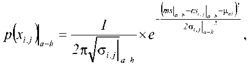
- said probability distribution is based on a set of probabilities that the user equipment is within each one of the plurality of elementary area elements in which the geographic area is subdivided, the set of probabilities comprising a probability in respect of each radio communication station of the at least one radio communication station.
- each probability of the set of probabilities is computed as: p x i , j
- a ⁇ h 1 2 ⁇ ⁇ i , j
- a-h is the expected radio signal strength in the respective one of the elementary area elements of the plurality of elementary area elements
- a-h is the standard deviation of a statistical error associated with said expected radio signal strength in the respective one of the plurality of elementary area elements
- a-h is the measured radio signal strength measurement and ⁇ ni initial attenuation of the n -th iteration.
- each probability of the set of probabilities is normalized into a corresponding normalized probability before being used as a basis for said probability distribution.
- said probability distribution is defined by a set of total probabilities each of which is computed as a product of the normalized probabilities associated with a same elementary area element of the plurality of elementary area elements.
- the method further comprises the step of g) computing average expected radio signal strengths as an average of the expected radio signal strengths of each elementary area element comprised in the uncertainty area, and wherein the step e) comprises computing the final attenuation as an average of the differences between the average expected radio signal strengths and the measured radio signal strengths.
- Another aspect of the present invention proposes a wireless communication network comprising a plurality of radio communication stations transmitting radio signals over a geographic area adapted to implement the method of above.
- the wireless communication network is a mobile telephony network.
- the wireless communication network is a Global Navigation Satellite System network.
- Figure 1 is a schematic view of a portion of a wireless communication network in which an embodiment of the present invention can be implemented.
- a generic wireless communication network 100 allows and manages communications over a coverage area (not shown) of user equipments or UE (e.g., mobile telephones, smartphones and tablets). Such a (geographic) coverage area is generally subdivided in a plurality of portions, such as the cell 105 in which communication is managed by a radio communication station.
- UE user equipments or UE
- Such a (geographic) coverage area is generally subdivided in a plurality of portions, such as the cell 105 in which communication is managed by a radio communication station.
- one or more radio transceivers (not shown) of a radio communication station 110a such as an evolved Node B, or eNodeB in 3GPP Long Term Evolution (LTE)/LTE Advanced (LTE-A) systems, manage communications (i.e., transmission and/or reception of information, such as binary data packets) of the UE within the radio communication station coverage area or cell 105.
- LTE Long Term Evolution
- LTE-A LTE Advanced
- a plurality of neighboring radio communication stations 110b-h (of which only seven are shown in the example of Figure 1 ) manage the communication within respective cells (not shown) which are neighbor of the cell 105.
- the coverage area is ideally subdivided into relatively small, elementary area elements or pixels x i,j (where 1 ⁇ i ⁇ I and 1 ⁇ j ⁇ J, with I and J positive integer numbers), each pixel being an elementary, unit (in the shown example, the pixel are squares in shape) area of predefined width, e.g. 1" of latitude by 1" of longitude (even though different pixels not necessarily have the same size or shape). Therefore each cell, such as the cell 105, of the wireless communication network 100 is subdivided into a plurality of pixels x i,j .
- a-h , produced by the radio communication stations 110a-h on the generic pixel x i,j are measured or calculated, e.g. by means of known radio signal propagation simulation tools or through an estimation taking into account the path loss model in each pixel and radio communication parameters (i.e. emitted power, antenna gain, antenna position) of the radio communication stations, and they are compared one another.
- Each pixel x i,j is then associated with the respective radio communication station 110a-h which, compared to all the other radio communication stations 110a-h, produces in the pixel x i,j the best expected signal strengths es i,j
- the set of pixels x i,j associated with a same radio communication station, such as the radio communication station 110a define the cell, such as the cell 105, of the respective radio communication station.
- a-h measured or calculated by the radio signal propagation simulation tools or based on the above cited path loss estimation generate a RF signals strength map, which is a database that, for each pixel x i,j , comprises the expected signal strengths es i,j
- a-h further comprises an indication of a statistical error, such as a standard deviation ⁇ i,j
- the RF signals strength map of the wireless communication network 100 may have been already generated during a network planning phase of the wireless communication network 100 and therefore such a RF signals strength map may be used for positioning and tracking purposes, without the need of generating a new RF signals strength map.
- the wireless communication network 100 has a certain positioning capability, i.e. the wireless communication network 100 may provide a rough estimation of the position, within its coverage area, of UE (not shown).
- the wireless communication network 100 knows in which cell, e.g. the cell 105, the UE is located, since the wireless communication network 100 is aware of the radio communication station, e.g. the radio communication station 110a, associated with (i.e., serving) such UE. Furthermore, the wireless communication network may identify in which portion of cell or sector of the cell 105 the UE is located by identifying with which radio transceivers of the radio communication station 110a the UE is associated.
- the wireless communication network 100 may identify a distance between the UE and the radio communication station 110a by means of a timing advance value corresponding to the length of time a signal takes to reach the communication station from the UE. Therefore, the wireless communication network may identify a portion of the sector of the cell 105 in which the UE is located. Such sector portion can be used as an initial search space 120 for accurately locating the UE in a method according to an embodiment of the present invention.
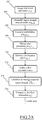
- FIGS. 2A - 2C they are a schematic flowchart of a positioning method according to an embodiment of the present invention.
- a initialization phase comprising a first and a second UE position estimation cycles is performed.
- the first UE position estimation cycle determines a first UE estimated position of a UE inside the search space 120.
- a first initial attenuation value or simply first initial attenuation ⁇ 1i , is assigned to each pixel x i,j of the search space 120 (step 202 ) for taking into account a probable signal attenuation experienced by signals transmitted by the serving radio communication station taking into account losses not considered in the expected signal strengths for each pixel in the RF signals strength map.
- the first initial attenuation ⁇ 1i is a constant value selected from a table of attenuation values that lists a plurality of attenuation values for not modeled obstacle(s) (for example, 8dB if an in-vehicle scenario should be considered).
- a-h measured by the UE with respect to each one of the radio communication stations 110a-h are obtained.
- a-h are periodically sent by UE to the wireless communication network 100 for call management and, moreover, the measurements may also be requested by the wireless communication network 100 to the UE even when no radio link is set up (i.e., an active connection for performing communication).
- a set of probabilities that the UE is within the generic pixel x i,j of the search space 120 is determined for each pixel of the search space 120.
- the set of probabilities preferably comprises a probability p(x i,j )
- a-h can be computed (one for each of the - eight in the considered example - radio communication stations 110a-h ) according to the following formula: p x i , j
- a ⁇ h 1 2 ⁇ ⁇ i , j
- a-h are used in the subsequent calculations, where the normalized probabilities p norm (x i,j )
- a-h are calculated as follows: p norm x i , j
- a ⁇ h p x i , j
- a ⁇ h 1 2 ⁇ ⁇ i , j
- a-h are then combined (step 208 ) in such a way to obtain a total probability p(x i,j )
- tot for the pixel x i,j can for example be computed as a product of the (eight in the considered example) probabilities p norm (x i,j )
- tot of all the pixels x i,j of the search space 120 define a first position probability distribution d 1 (x i,j ) of the (possible) position of the UE in the search space 120 that has generally a Gaussian shape.
- 1 is identified (step 210 ).
- a first center of mass, or first centroid C 1d , of the search space 120 is determined based on the total probabilities p(x i,j )
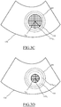
- a first uncertainty area 305 is defined.
- Figure 3A is a schematic view of the search space 120 showing the first uncertainty area 305 in which the UE whose position is to be determined is located according to an embodiment of the present invention
- the first uncertainty area 305 is defined as a circular area of the search space 120 centered on the first location pixel x i,j
- a radius of the first uncertainty area 305 is defined as substantially corresponding to a first standard deviation ⁇ 1d of the first position probability distribution d 1 (x i,j ) computed centered in the first location pixel x i,j
- the generic pixel x i,j of the search space 120 being associated with a first maximum M 1d of the first position probability distribution d 1 (x i,j ) is selected as the first location pixel x i , j
- the radius of the first uncertainty area 305 is defined as the first standard deviation ⁇ 1d of the first position probability distribution d 1 (x i,j ) computed centered at the first location pixel x i,j
- a first final attenuation ⁇ 1f is computed at the end of the first position estimation cycle (steps 214 and 216 ). Since the estimation of the UE position is affected by an error, the calculation of the expected signal strength should take into account an average expected signal strength estimated over the uncertainty area, by using a plurality of pixels around the estimated position.
- step 214 average expected signal strengths ES
- the first final attenuation ⁇ 1f is computed as the average of the (eight, in the considered example) differences between the average expected signal strengths ES
- the first position estimation cycle ends.
- the method provides a first position estimation for the UE whose position is to be identified, i.e. the first location pixel x i,j
- the estimation of the UE position can be re-calculated by replacing the first initial attenuation ⁇ 1i with the first final attenuation ⁇ 1f resulting at the end of the first position estimation.
- the second position estimation cycle starts.
- the second position estimation cycle performs substantially the same steps as the first position estimation cycle but uses the first final attenuation ⁇ 1f calculated at the end of the first position estimation cycle as second initial attenuation ⁇ 2i (step 218 ).
- a-h are obtained (or, alternatively, the same measured RF signal strengths ms
- a-h calculated for the generic pixel x i,j of the first uncertainty area 305 are then combined (step 224 ) in such a way to obtain, for that generic pixel x i,j of the first uncertainty area 305, a total probability p(x i,j )
- a second centroid C 2d of the first uncertainty area 305 is determined, and a second location pixel x i,j
- a second uncertainty area 310 is defined, as shown in Figure 3B , which is a schematic view of the search space 120 showing the second uncertainty area 310 in which the UE whose position is to be determined is located according to an embodiment of the present invention.
- a radius of second uncertainty area 310 is defined as substantially corresponding to a second standard deviation ⁇ 2d of the second position probability distribution d 2 (x i,j ) computed centered at the second location pixel x i,j
- a second final attenuation ⁇ 2f is computed at the end of the second position estimation cycle (steps 230 and 232 ) analogously to the first position estimation cycles, i.e. average expected signal strengths ES
- the method provides a second position estimation for the UE whose position is to be identified, i.e. the second location pixel x i,j
- the first centroid C 1d (or the first maximum M 1d ) used as the center of the first uncertainty area 305 and the second centroid C 2d (or the second maximum M 2d ) used as the center of the second uncertainty area 310 do not necessarily correspond. Therefore, the first uncertainty area 305 and the second uncertainty area 310 are generally eccentric areas.
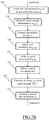
- the positioning initialization phase ends and subsequent position estimation cycles are preferably performed in the following manner.
- the generic n -th position estimation cycle performs the same steps of the first position estimation cycle but uses a n -th initial attenuation ⁇ ni based on a combination of two or more of the previously calculated final attenuations ⁇ 1f to ⁇ n-1f (step 234 ).
- the n -th initial attenuation ⁇ ni may be computed in a plurality of different manner; for example, the n -th initial attenuation ⁇ ni may be computed depending on whether the UE whose position is to be estimated is moving or has a substantially static position in order to obtain a better estimation of the position of the UE.
- the n -th initial attenuation ⁇ ni may be computed by averaging only a subset of the previously calculated final attenuations ⁇ 1f to ⁇ n-1f , for example by calculating a moving average calculated by taking a moving "averaging window" that may be defined for computing the n -th initial attenuation ⁇ ni and which comprises a certain number k of previously calculated final attenuations ⁇ n-kf to ⁇ n-1f .
- a moving averaging window may be particularly advantageous in case the not modeled environment conditions introduce signal attenuations change over time (e.g., in case the UE moved from inside a building to the outdoor environment). Indeed, during UE movements in the area of coverage of the wireless communication network 100, the not modeled attenuation affecting radio signals may vary; therefore, taking into account the whole set of attenuations already computed in the past may be misleading if a movement of the UE to be positioned is detected.
- the n -th initial attenuation ⁇ ni may be computed as a weighted average of some or more, possibly all the previously calculated final attenuations ⁇ 1f to ⁇ n - 1f .
- the weights may be defined on the basis of an exponential decreasing function.
- n -th position estimation cycle new measured RF signal strengths ms
- a-h calculated for the generic pixel x i,j of the ( n-1) -th uncertainty area 315 n-1 are then combined (step 240 ) in such a way to obtain, for that generic pixel x i,j of the ( n-1) -th uncertainty area 315 n-1 , a total probability p(x i,j )
- a n -th center of mass C nd for the n -th uncertainty area 315 n is determined, and a n -th location pixel x i,j
- n is identified as corresponding to the n -th center of mass C nd (or, alternatively, to the n -th maximum M nd of the corresponding position probability distribution d n (x i,j )) (step 242 ).
- a n -th uncertainty area 315 n is defined - as shown in Figure 3D , which is a schematic view of the search space 120 showing the n -th uncertainty area 315 n in which the UE whose position is to be determined is located.
- a radius of the n -th uncertainty area 315 n is defined as substantially corresponding to a n -th standard deviation ⁇ nd of the n -th position probability distribution d n (x i,j ) computed centered at the n -th location pixel x i,j
- n -th centroid C 2d (or alternatively as a n -th standard deviation ⁇ nd centered in the n -th maximum M nd of the n -th position probability distribution d n (x i,j ) ).
- a n -th final attenuation ⁇ nf is computed (steps 246 and 248 ).
- a-h are calculated (steps 246 ) for the whole n -th uncertainty area 315 n , i.e.: E S
- the n -th final attenuation ⁇ nf is computed as the average of the (eight, in the considered example) differences between the average expected signal strengths ES
- the method provides a n -th estimation of the position estimation for the UE whose position is to be determined, i.e. the n -th location pixel x i,j
- step 234 for refining further the position estimation by performing a further position estimation cycle (i.e., the steps 234 to 248 are reiterated).
- the n -th final attenuation ⁇ nf may be excluded and not used in determining the next (n + 1) -th initial attenuation.
- the (n + 1) -th initial attenuation is not based on the immediately previous n -th final attenuation ⁇ nf (but only based on final attenuations comprised in a set going from the first final attenuation ⁇ 1f to the (n-1) -th final attenuation)
- a-h at the (n + 1) -th step are independent one another and the total probabilities p(x i,j )
- the method according to an embodiment of the invention it is possible to perform a continuous and self-refining positioning and a tracking of UE within the wireless communication network that take into account estimation of losses due to obstacles that cannot be included in models used by RF signal strength prediction tools or path loss estimation for generating the RF signals strength map; thus an improved accuracy in the positioning of UE within the wireless communication network is attained.
- the method according to an embodiment of the invention is adapted to refine at each cycle the attenuation value starting from a selected value to a final value substantially corresponding to a real attenuation term affecting the signal to/from the UE; therefore the method according to an embodiment of the invention is particularly adapted for positioning and tracking purposes even when measured signal strengths are affected by attenuations caused by additional obstacles such as vehicles (i.e., when the UE is within a vehicle), the foliage that varies according to the season, walls of building (when the UE is within a building, whose walls losses are not known), or the elevation of the position of the user handling the UE in a building with respect to the ground level (which in a first approximation may cause an increase of the signal strength) which vary in time and/or that cannot be successfully modeled in radio propagation tools.
- vehicles i.e., when the UE is within a vehicle
- the foliage that varies according to the season i.e., when the UE is within a vehicle
- walls of building when
- the wireless communication network is a satellite communication or navigation system such as the Global Navigation Satellite System (GNSS), such as GPS, Glonass or Galileo.
- GNSS Global Navigation Satellite System
- GPS GPS, Glonass or Galileo.
- UE signal strength measurements are obtained in respect of signals provided by GNSS satellites in view and/or ground repeater antennas in range and expected signal strength are obtained from a corresponding GNSS signal strength map.
- the positioning method described above with respect to the wireless communication network 100 for mobile telephony may be substantially straightforwardly applied to a Global Navigation Satellite System, by using, as expected signal strengths es i,j
- a-h represent measures, performed by the UEs, of the received GNSS signals.
- an initial GNSS positioning is more accurate that an initial positioning (i.e., the search area 120 ) provided by the mobile telephony network
- the loss (i.e. the attenuation) estimation is more accurate and the positioning and tracking achievable through the proposed invention provides an even better accuracy than in the case of mobile telephony networks.
- the accuracy of correction of the estimation of the position of UE exploiting GNSS signal strength maps may be improved by implementing the method end system according to the present invention in scenarios where the accuracy of the GNSS positioning may be degraded, such as for example in urban canyons scenario where the shadowing and the diffraction of RF signals caused by buildings may reduce an number of GNSS satellites actually in view and/or cause electromagnetic fields propagation delays (i.e., delays that affect the RF signals).
Landscapes
- Engineering & Computer Science (AREA)
- Radar, Positioning & Navigation (AREA)
- Remote Sensing (AREA)
- Physics & Mathematics (AREA)
- General Physics & Mathematics (AREA)
- Computer Networks & Wireless Communication (AREA)
- Probability & Statistics with Applications (AREA)
- Signal Processing (AREA)
- Mobile Radio Communication Systems (AREA)
- Position Fixing By Use Of Radio Waves (AREA)
Claims (18)
- Verfahren zum Identifizieren einer Position eines Benutzergeräts in einem drahtlosen Kommunikationsnetzwerk (100), das mindestens eine Funkkommunikationsstation (110a-h) umfasst, die Funksignale über einen geographischen Bereich überträgt, wobei das Verfahren dadurch gekennzeichnet ist, dass es die folgenden Schritte umfasst:a) Bereitstellen erwarteter Funksignalstärken (es ij|a-h ), die durch die mindestens eine Funkkommunikationstation an jedem von einer Vielzahl von Elementarbereichselementen (x i,j ) produziert werden, in die der geographische Bereich unterteilt ist;b) Definieren (202, 218, 234) einer Anfangsdämpfung (µ1i, µ2i, µn-1i, µni), die die Funksignale erfahren, die dem Benutzergerät, dessen Position identifiziert werden soll, durch die mindestens eine Funkkommunikationsstation (110a-h) bereitgestellt werden;c) Erhalten (204, 220, 236) von gemessenen Funksignalstärkemessungen (ms| a-h ) der Funksignale, die dem Benutzergerät bereitgestellt werden, dessen Position identifiziert werden soll;d) Bestimmen (206,208,210, 222,224,226, 238,240,242) eines geschätzten Elementarbereichelements (x i,j|1, x i,j|2, x i,j|(n-1), x i,j|n ), das der Position des Benutzergeräts entspricht, dessen Position auf der Basis der erwarteten Funksignalstärken (es ij|a-h ), der Anfangsdämpfung (µ1i, µ2i, µn-1i, µni) und der Funksignalstärkemessungen (ms| a-h ) identifiziert werden soll, unde) Berechnen (216, 234, 248) einer endgültigen Dämpfung (µ1f, µ2f, µn-1f, µnf) auf der Basis des geschätzten Elementarbereichelements (x i,j|1, x i,j|2, x i,j|n ),wobei die Schritte b) bis e) mindestens zwei Iterationen mit jeder weitere Iteration des Schrittes b) durchlaufen, der Definieren (218, 234) der jeweiligen Anfangsdämpfung (µ2i, µn-1i, µni) für jede weitere Iteration auf der Basis von mindestens einer endgültigen Dämpfung (µ1f, µ2f, µn-1f, µnf) umfasst, die zuvor in Schritt e) von mindestens einer vorhergehenden Iteration berechnet wurde.
- Verfahren nach Anspruch 1, wobei eine zweite Iteration des Schrittes b) Definieren der endgültigen Dämpfung (µ1f), die während der ersten Iteration von Schritt e) berechnet wurde, als Anfangsdämpfung (µ2i) umfasst.
- Verfahren nach Anspruch 1 oder 2, wobei jede weitere Iteration des Schrittes b) Definieren eines Mittelwerts der zuvor berechneten endgültigen Dämpfungen (µ1f, µ2f, µn-1f) als Anfangsdämpfung (µ2i, µn-1i, µni) umfasst.
- Verfahren nach Anspruch 1 oder 2, wobei jede weitere Iteration des Schrittes b) Definieren eines Mittelwerts mindestens eines Teils der zuvor berechneten endgültigen Dämpfungen (µ1f, µ2f, µn-1f) als Anfangsdämpfung (µ2i, µn-1i, µni) umfasst.
- Verfahren nach Anspruch 3 oder 4, wobei der Mittelwert ein gewichteter Mittelwert ist.
- Verfahren nach Anspruch 5, wobei der gewichtete Mittelwert Gewichtungen umfasst, die auf einer exponentiell abnehmenden Funktion basieren.
- Verfahren nach einem der vorhergehenden Ansprüche, wobei der Schritt d) Ermitteln (206,208,210, 222,224,226, 238,240,242) des geschätzten Elementarbereichelements (xi,j|1, xi,j|2, Xi,j|(n-1), Xi,j|n) auf Basis einer Wahrscheinlichkeitsverteilung (d1(xi,j), d2(xi,j), dn(xi,j)) der Position des Benutzergeräts in der Vielzahl der Elementarbereichelemente umfasst, in die der geographische Bereich unterteilt ist.
- Verfahren nach Anspruch 7, wobei der Schritt d) Ermitteln einer Standardabweichung (∑ 1d , ∑ 2d , ∑((n-1)d, ∑ nd) der Wahrscheinlichkeitsverteilung (d(xi,j) umfasst und das Verfahren ferner den folgenden Schritt umfasst:
f) Definieren (212, 214, 216) eines Unsicherheitsbereichs (305, 310, 315n-1, 315n ), der auf dem geschätzten Elementarbereichelement (xi,j|1, xi,j|2, xi,j|(n-1), xi,j|n ) zentriert ist und einen Radius aufweist, der im Wesentlichen der Standardabweichung (∑ 1d , ∑ 2d , ∑( (n-1)d , ∑ nd) entspricht. - Verfahren nach Anspruch 7 oder 8, wobei der Schritt d) Ermitteln (210, 226, 242) des geschätzten Elementarbereichelements (xi,j|1, xi,j|2, xi,j|(n-i), xi,j|n ) als Maximum {M1d, M2d , M(n-1)d, Mnd ) der Wahrscheinlichkeitsverteilung (d1(xi,j), d2(xi,j), dn(xi,j)) umfasst.
- Verfahren nach Anspruch 8, wobei der Schritt d) Ermitteln (210, 226, 242) des geschätzten Elementarbereichelements (x i,j|1, x i,j|2, x i,j|(n-1) , x i,j|n) als Massenschwerpunkt (C1d, C2d, Cnd ) eines Unsicherheitsbereichs (305, 310, 315n-1, 315n ), der während einer vorhergehenden Iteration der Schritte b) bis e) berechnet wurde, oder eines Anfangssuchraums (120) in einer ersten Iteration der Schritte b) bis e) umfasst.
- Verfahren nach einem der vorhergehenden Ansprüche 7 bis 10, wobei die Wahrscheinlichkeitsverteilung (d1(xi,j), d2(xi,j), dn(xi,j)) auf einem Satz von Wahrscheinlichkeiten basiert, dass das Benutzergerät innerhalb eines jeden von der Vielzahl von Elementarbereichelementen (xi,j ) ist, in die der geographische Bereich unterteilt ist, wobei der Satz der Wahrscheinlichkeiten eine Wahrscheinlichkeit (p(xi,j)| a-h) in Bezug auf jede Funkkommunikationsstation (110a-h) der mindestens einen Funkkommunikationsstation (110a-h) umfasst.
- Verfahren nach Anspruch 11, wobei jede Wahrscheinlichkeit (p(xi,j)| a-h) des Satzes von Wahrscheinlichkeiten berechnet (206, 222, 238) wird als:
- Verfahren nach Anspruch 12, wobei jede Wahrscheinlichkeit (p(xi,j)| a-h) des Satzes von Wahrscheinlichkeiten zu einer entsprechenden normalisierten Wahrscheinlichkeit (pnorm(xi,j)| a-h) normalisiert wird, bevor sie als Basis für die Wahrscheinlichkeitsverteilung (d1(xi,j), d2(xi,j), dn(xi,j) verwendet wird.
- Verfahren nach Anspruch 13, wobei die Wahrscheinlichkeitsverteilung (dj(xi,j), d2(xi,j), dn(xi,j)) durch einen Satz von Gesamtwahrscheinlichkeiten (p(xi,j)| tot) definiert ist, von denen jede als Produkt der normalisierten Wahrscheinlichkeiten (pnorm(xi,j)| a-h) berechnet (208, 224, 240) wird, die mit dem selben Elementarbereichelement (xi,j) von der Vielzahl der Elementarbereichelemente zusammenhängen.
- Verfahren nach einem der vorhergehenden Ansprüche in Abhängigkeit von Anspruch 8, ferner umfassend den Schritt:
g) Berechnen (214, 230, 246) von durchschnittlichen erwarteten Funksignalstärken (ES |a-h ) als Mittelwert der erwarteten Funksignalstärken (es ij|a-h ) von jedem Elementarbereichelement (xi,j), das in dem Unsicherheitsbereich (305, 310, 315n-i, 315n ) enthalten ist, und
wobei der Schritt e) Berechnen der endgültigen Abschwächung (µ1f, µ2f, µn-1f, µnf) als Mittelwert der Differenzen zwischen den durchschnittlichen erwarteten Funksignalstärken ((ES | a-h) und den gemessenen Funksignalstärken (ms| a-h ) umfasst. - Drahtloskommunikationsnetzwerk (100), umfassend eine Vielzahl von Funkkommunikationsstationen (110a-h), die Funksignale über einen geographischen Bereich übertragen, welches angepasst ist, um das Verfahren gemäß einem der vorhergehenden Ansprüche 1 bis 15 zu implementieren.
- Drahtloskommunikationsnetzwerk (100) nach Anspruch 16, wobei das Drahtloskommunikationsnetzwerk (100) ein Mobiltelefonnetzwerk ist.
- Drahtloskommunikationsnetzwerk (100) nach Anspruch 16, wobei das Drahtloskommunikationsnetzwerk (100) ein globales Navigationssatellitensystemnetzwerk ist.
Applications Claiming Priority (1)
| Application Number | Priority Date | Filing Date | Title |
|---|---|---|---|
| PCT/EP2014/070745 WO2016050258A1 (en) | 2014-09-29 | 2014-09-29 | Positioning method and system for wireless communication networks |
Publications (2)
| Publication Number | Publication Date |
|---|---|
| EP3201645A1 EP3201645A1 (de) | 2017-08-09 |
| EP3201645B1 true EP3201645B1 (de) | 2018-06-06 |
Family
ID=51752090
Family Applications (1)
| Application Number | Title | Priority Date | Filing Date |
|---|---|---|---|
| EP14786456.5A Active EP3201645B1 (de) | 2014-09-29 | 2014-09-29 | Positionierungsverfahren und -system für drahtloskommunikationsnetzwerke |
Country Status (5)
| Country | Link |
|---|---|
| US (1) | US11852741B2 (de) |
| EP (1) | EP3201645B1 (de) |
| KR (1) | KR20170060129A (de) |
| CN (1) | CN107076828B (de) |
| WO (1) | WO2016050258A1 (de) |
Cited By (1)
| Publication number | Priority date | Publication date | Assignee | Title |
|---|---|---|---|---|
| US11452066B2 (en) * | 2020-10-16 | 2022-09-20 | Hughes Network Systems | Estimating geolocation of a user terminal |
Families Citing this family (13)
| Publication number | Priority date | Publication date | Assignee | Title |
|---|---|---|---|---|
| US10342067B2 (en) * | 2016-07-11 | 2019-07-02 | Veniam, Inc. | Systems and methods for vehicular positioning based on wireless fingerprinting data in a network of moving things including, for example, autonomous vehicles |
| EP3309587B1 (de) | 2016-10-11 | 2021-12-08 | Signify Holding B.V. | Positionierungssystem und positionierungsverfahren |
| KR102612792B1 (ko) * | 2016-10-28 | 2023-12-13 | 삼성전자주식회사 | 전자 장치 및 전자 장치의 관심 영역 진입 판단 방법 |
| CN108008351B (zh) * | 2017-11-29 | 2021-05-14 | 徐小文 | 一种基于正向衰减逆推发射幅度聚集性的信号定位方法 |
| EP3499263B1 (de) * | 2017-12-12 | 2022-09-21 | Rohde & Schwarz GmbH & Co. KG | Peilsystem und verfahren zur funkpeilung eines zieles |
| CA3108520A1 (en) | 2018-08-02 | 2020-02-06 | Lutron Technology Company Llc | Camera-based commissioning |
| EP3668197B1 (de) | 2018-12-12 | 2021-11-03 | Rohde & Schwarz GmbH & Co. KG | Verfahren und funkgerät zur einstellung der übertragungsleistung einer funkübertragung |
| DE102019206466A1 (de) * | 2019-05-06 | 2020-11-12 | Robert Bosch Gmbh | Verfahren und Vorrichtung zum Betreiben eines drahtlosen Kommunikationsnetzwerks |
| CN112188603B (zh) * | 2019-07-05 | 2023-07-18 | 北京小米移动软件有限公司 | 功率控制方法、装置及存储介质 |
| WO2021144077A1 (en) * | 2020-01-17 | 2021-07-22 | British Telecommunications Public Limited Company | Wireless telecommunications network |
| EP4047382A1 (de) * | 2021-02-18 | 2022-08-24 | Nokia Technologies Oy | Hf-fingerdruckkartenaktualisierung |
| US20220398417A1 (en) * | 2021-06-15 | 2022-12-15 | Samsung Electronics Co., Ltd. | Methods and systems for maximum consistency based outlier handling |
| EP4690566A1 (de) * | 2023-03-29 | 2026-02-11 | Rakuten Symphony, Inc. | Systeme und verfahren zur visualisierung eines auf geolokalisierung basierenden schlüsselleistungsindikators in einem telekommunikationsnetzwerk |
Family Cites Families (18)
| Publication number | Priority date | Publication date | Assignee | Title |
|---|---|---|---|---|
| JPS62173835A (ja) * | 1986-01-28 | 1987-07-30 | Nec Corp | 基地局間干渉テ−ブル自動生成方式 |
| US6034635A (en) * | 1996-06-06 | 2000-03-07 | Gilhousen; Klein S. | Method for using only two base stations for determining the position of a mobile subscriber in a CDMA cellular telephone system |
| US6393294B1 (en) | 1998-09-22 | 2002-05-21 | Polaris Wireless, Inc. | Location determination using RF fingerprinting |
| DE10157941A1 (de) * | 2001-11-27 | 2003-06-05 | Alcatel Sa | Verfahren zur Positionsbestimmung einer Mobilstation auf der Basis von Ausbreitungsmodellen |
| US20050059406A1 (en) * | 2003-09-17 | 2005-03-17 | Trapeze Networks, Inc. | Wireless LAN measurement feedback |
| US8045996B2 (en) * | 2006-07-31 | 2011-10-25 | Qualcomm Incorporated | Determination of cell RF parameters based on measurements by user equipments |
| US20080037689A1 (en) * | 2006-08-09 | 2008-02-14 | Tolga Kurt | Adaptive Kalman filtering for fast fading removal |
| US7626969B2 (en) | 2006-10-04 | 2009-12-01 | Cisco Technology, Inc. | Relative location of a wireless node in a wireless network |
| US8112261B2 (en) * | 2008-03-31 | 2012-02-07 | Gm Global Technology Operations, Llc. | Methods and simulation tools for predicting GPS performance in the broad operating environment |
| KR20110083542A (ko) | 2010-01-13 | 2011-07-20 | 한국전자통신연구원 | 무선 측위 방법 및 장치, 그리고 이동국 |
| US8442552B2 (en) * | 2010-04-23 | 2013-05-14 | Hewlett-Packard Development Company, L.P. | Method and system for radio frequency coverage prediction in a multi-level wireless network |
| CN102395192B (zh) * | 2011-03-15 | 2014-09-24 | 苏州摩多物联科技有限公司 | 一种无线传感终端的定位方法和装置 |
| US8755869B2 (en) * | 2011-04-29 | 2014-06-17 | Cyberonics, Inc. | Adjusting neighborhood widths of candidate heart beats according to previous heart beat statistics |
| JP2013143663A (ja) * | 2012-01-11 | 2013-07-22 | Takeshi Hatsuda | 近距離の2地球局を使用したサテライトダイバーティ方式 |
| US9121922B2 (en) * | 2012-06-26 | 2015-09-01 | Cambridge Silicon Radio Limited | Access point location identification methods and apparatus based on absolute and relative harvesting |
| US8977298B2 (en) | 2012-12-14 | 2015-03-10 | Apple Inc. | Location fingerprinting |
| US10347269B2 (en) * | 2013-03-12 | 2019-07-09 | Hear Ip Pty Ltd | Noise reduction method and system |
| CN103605110B (zh) * | 2013-12-03 | 2016-01-20 | 北京理工大学 | 基于接收信号强度的室内无源目标定位方法 |
-
2014
- 2014-09-29 US US15/514,932 patent/US11852741B2/en active Active
- 2014-09-29 KR KR1020177011227A patent/KR20170060129A/ko not_active Ceased
- 2014-09-29 CN CN201480082965.8A patent/CN107076828B/zh active Active
- 2014-09-29 EP EP14786456.5A patent/EP3201645B1/de active Active
- 2014-09-29 WO PCT/EP2014/070745 patent/WO2016050258A1/en not_active Ceased
Non-Patent Citations (1)
| Title |
|---|
| None * |
Cited By (4)
| Publication number | Priority date | Publication date | Assignee | Title |
|---|---|---|---|---|
| US11452066B2 (en) * | 2020-10-16 | 2022-09-20 | Hughes Network Systems | Estimating geolocation of a user terminal |
| US20220394661A1 (en) * | 2020-10-16 | 2022-12-08 | Hughes Network Systems, Llc | Estimating geolocation of a user terminal |
| US11716702B2 (en) * | 2020-10-16 | 2023-08-01 | Hughes Network Systems, Llc | Estimating geolocation of a user terminal |
| EP4229426A1 (de) * | 2020-10-16 | 2023-08-23 | Hughes Network Systems, LLC | Schätzung der geolokalisierung eines benutzerendgeräts |
Also Published As
| Publication number | Publication date |
|---|---|
| US20170219681A1 (en) | 2017-08-03 |
| CN107076828A (zh) | 2017-08-18 |
| KR20170060129A (ko) | 2017-05-31 |
| CN107076828B (zh) | 2020-06-05 |
| EP3201645A1 (de) | 2017-08-09 |
| WO2016050258A1 (en) | 2016-04-07 |
| US11852741B2 (en) | 2023-12-26 |
Similar Documents
| Publication | Publication Date | Title |
|---|---|---|
| EP3201645B1 (de) | Positionierungsverfahren und -system für drahtloskommunikationsnetzwerke | |
| JP4578505B2 (ja) | 無線端末の居場所の予測方法 | |
| EP1757138B1 (de) | Finden von mobilen endgeräten | |
| US7848762B2 (en) | Computationally-efficient estimation of the location of a wireless terminal based on pattern matching | |
| US8965393B2 (en) | Estimating the location of a wireless terminal based on assisted GPS and pattern matching | |
| US7753278B2 (en) | Estimating the location of a wireless terminal based on non-uniform locations | |
| EP3293539B1 (de) | Verwendung von mobilstationen zur bestimmung von basisstationstandortparametern in einem drahtlosen mobilen kommunikationssystem | |
| US9844019B1 (en) | Estimating the location of a wireless terminal in wireless telecommunications systems that comprise distributed and/or repeater antennas | |
| US20080299993A1 (en) | Computationally-Efficient Estimation of the Location of a Wireless Terminal Based on Pattern Matching | |
| JP2007316069A (ja) | 無線端末の居場所の予測方法 | |
| US9462421B1 (en) | Indoor-outdoor detector for estimating the location of a wireless terminal | |
| US20120282947A1 (en) | Estimating the Location of a Wireless Terminal Based on Signal Path Impairment | |
| US11930041B2 (en) | Generalized localization system based on physical layer supported spoofing detection and identification verification | |
| Ahonen et al. | Mobile terminal location for UMTS | |
| Vaghefi et al. | Cooperative RF pattern matching positioning for LTE cellular systems | |
| EP2934052A1 (de) | Verfahren, Basisstation, System und computerlesbares Medium zur Lokalisierung einer Benutzervorrichtung | |
| US8493205B2 (en) | Search area reduction based on indoor detection for estimating the location of a wireless terminal | |
| US10123298B1 (en) | Estimating the location of a wireless terminal based on detection of whether it is moving or stationary | |
| US9817103B2 (en) | Position adjustment in mobile communications networks | |
| Markoulidakis | Received signal strength based mobile terminal positioning error analysis and optimization | |
| Markoulidakis | OPTIMIZATION OF KALMAN FILTERING PERFORMANCE IN RECEIVED SIGNAL STRENGTH BASED MOBILE POSITIONING |
Legal Events
| Date | Code | Title | Description |
|---|---|---|---|
| PUAI | Public reference made under article 153(3) epc to a published international application that has entered the european phase |
Free format text: ORIGINAL CODE: 0009012 |
|
| 17P | Request for examination filed |
Effective date: 20170421 |
|
| AK | Designated contracting states |
Kind code of ref document: A1 Designated state(s): AL AT BE BG CH CY CZ DE DK EE ES FI FR GB GR HR HU IE IS IT LI LT LU LV MC MK MT NL NO PL PT RO RS SE SI SK SM TR |
|
| AX | Request for extension of the european patent |
Extension state: BA ME |
|
| DAX | Request for extension of the european patent (deleted) | ||
| GRAP | Despatch of communication of intention to grant a patent |
Free format text: ORIGINAL CODE: EPIDOSNIGR1 |
|
| INTG | Intention to grant announced |
Effective date: 20180205 |
|
| GRAS | Grant fee paid |
Free format text: ORIGINAL CODE: EPIDOSNIGR3 |
|
| GRAA | (expected) grant |
Free format text: ORIGINAL CODE: 0009210 |
|
| AK | Designated contracting states |
Kind code of ref document: B1 Designated state(s): AL AT BE BG CH CY CZ DE DK EE ES FI FR GB GR HR HU IE IS IT LI LT LU LV MC MK MT NL NO PL PT RO RS SE SI SK SM TR |
|
| REG | Reference to a national code |
Ref country code: GB Ref legal event code: FG4D |
|
| REG | Reference to a national code |
Ref country code: CH Ref legal event code: EP Ref country code: AT Ref legal event code: REF Ref document number: 1006706 Country of ref document: AT Kind code of ref document: T Effective date: 20180615 |
|
| REG | Reference to a national code |
Ref country code: IE Ref legal event code: FG4D |
|
| REG | Reference to a national code |
Ref country code: DE Ref legal event code: R096 Ref document number: 602014026717 Country of ref document: DE |
|
| REG | Reference to a national code |
Ref country code: FR Ref legal event code: PLFP Year of fee payment: 5 |
|
| REG | Reference to a national code |
Ref country code: NL Ref legal event code: MP Effective date: 20180606 |
|
| REG | Reference to a national code |
Ref country code: LT Ref legal event code: MG4D |
|
| PG25 | Lapsed in a contracting state [announced via postgrant information from national office to epo] |
Ref country code: SE Free format text: LAPSE BECAUSE OF FAILURE TO SUBMIT A TRANSLATION OF THE DESCRIPTION OR TO PAY THE FEE WITHIN THE PRESCRIBED TIME-LIMIT Effective date: 20180606 Ref country code: CY Free format text: LAPSE BECAUSE OF FAILURE TO SUBMIT A TRANSLATION OF THE DESCRIPTION OR TO PAY THE FEE WITHIN THE PRESCRIBED TIME-LIMIT Effective date: 20180606 Ref country code: ES Free format text: LAPSE BECAUSE OF FAILURE TO SUBMIT A TRANSLATION OF THE DESCRIPTION OR TO PAY THE FEE WITHIN THE PRESCRIBED TIME-LIMIT Effective date: 20180606 Ref country code: LT Free format text: LAPSE BECAUSE OF FAILURE TO SUBMIT A TRANSLATION OF THE DESCRIPTION OR TO PAY THE FEE WITHIN THE PRESCRIBED TIME-LIMIT Effective date: 20180606 Ref country code: BG Free format text: LAPSE BECAUSE OF FAILURE TO SUBMIT A TRANSLATION OF THE DESCRIPTION OR TO PAY THE FEE WITHIN THE PRESCRIBED TIME-LIMIT Effective date: 20180906 Ref country code: NO Free format text: LAPSE BECAUSE OF FAILURE TO SUBMIT A TRANSLATION OF THE DESCRIPTION OR TO PAY THE FEE WITHIN THE PRESCRIBED TIME-LIMIT Effective date: 20180906 Ref country code: FI Free format text: LAPSE BECAUSE OF FAILURE TO SUBMIT A TRANSLATION OF THE DESCRIPTION OR TO PAY THE FEE WITHIN THE PRESCRIBED TIME-LIMIT Effective date: 20180606 |
|
| PG25 | Lapsed in a contracting state [announced via postgrant information from national office to epo] |
Ref country code: GR Free format text: LAPSE BECAUSE OF FAILURE TO SUBMIT A TRANSLATION OF THE DESCRIPTION OR TO PAY THE FEE WITHIN THE PRESCRIBED TIME-LIMIT Effective date: 20180907 Ref country code: RS Free format text: LAPSE BECAUSE OF FAILURE TO SUBMIT A TRANSLATION OF THE DESCRIPTION OR TO PAY THE FEE WITHIN THE PRESCRIBED TIME-LIMIT Effective date: 20180606 Ref country code: HR Free format text: LAPSE BECAUSE OF FAILURE TO SUBMIT A TRANSLATION OF THE DESCRIPTION OR TO PAY THE FEE WITHIN THE PRESCRIBED TIME-LIMIT Effective date: 20180606 Ref country code: LV Free format text: LAPSE BECAUSE OF FAILURE TO SUBMIT A TRANSLATION OF THE DESCRIPTION OR TO PAY THE FEE WITHIN THE PRESCRIBED TIME-LIMIT Effective date: 20180606 |
|
| REG | Reference to a national code |
Ref country code: AT Ref legal event code: MK05 Ref document number: 1006706 Country of ref document: AT Kind code of ref document: T Effective date: 20180606 |
|
| PG25 | Lapsed in a contracting state [announced via postgrant information from national office to epo] |
Ref country code: NL Free format text: LAPSE BECAUSE OF FAILURE TO SUBMIT A TRANSLATION OF THE DESCRIPTION OR TO PAY THE FEE WITHIN THE PRESCRIBED TIME-LIMIT Effective date: 20180606 |
|
| PG25 | Lapsed in a contracting state [announced via postgrant information from national office to epo] |
Ref country code: SK Free format text: LAPSE BECAUSE OF FAILURE TO SUBMIT A TRANSLATION OF THE DESCRIPTION OR TO PAY THE FEE WITHIN THE PRESCRIBED TIME-LIMIT Effective date: 20180606 Ref country code: PL Free format text: LAPSE BECAUSE OF FAILURE TO SUBMIT A TRANSLATION OF THE DESCRIPTION OR TO PAY THE FEE WITHIN THE PRESCRIBED TIME-LIMIT Effective date: 20180606 Ref country code: EE Free format text: LAPSE BECAUSE OF FAILURE TO SUBMIT A TRANSLATION OF THE DESCRIPTION OR TO PAY THE FEE WITHIN THE PRESCRIBED TIME-LIMIT Effective date: 20180606 Ref country code: IS Free format text: LAPSE BECAUSE OF FAILURE TO SUBMIT A TRANSLATION OF THE DESCRIPTION OR TO PAY THE FEE WITHIN THE PRESCRIBED TIME-LIMIT Effective date: 20181006 Ref country code: RO Free format text: LAPSE BECAUSE OF FAILURE TO SUBMIT A TRANSLATION OF THE DESCRIPTION OR TO PAY THE FEE WITHIN THE PRESCRIBED TIME-LIMIT Effective date: 20180606 Ref country code: CZ Free format text: LAPSE BECAUSE OF FAILURE TO SUBMIT A TRANSLATION OF THE DESCRIPTION OR TO PAY THE FEE WITHIN THE PRESCRIBED TIME-LIMIT Effective date: 20180606 Ref country code: AT Free format text: LAPSE BECAUSE OF FAILURE TO SUBMIT A TRANSLATION OF THE DESCRIPTION OR TO PAY THE FEE WITHIN THE PRESCRIBED TIME-LIMIT Effective date: 20180606 |
|
| PG25 | Lapsed in a contracting state [announced via postgrant information from national office to epo] |
Ref country code: SM Free format text: LAPSE BECAUSE OF FAILURE TO SUBMIT A TRANSLATION OF THE DESCRIPTION OR TO PAY THE FEE WITHIN THE PRESCRIBED TIME-LIMIT Effective date: 20180606 |
|
| REG | Reference to a national code |
Ref country code: DE Ref legal event code: R097 Ref document number: 602014026717 Country of ref document: DE |
|
| PLBE | No opposition filed within time limit |
Free format text: ORIGINAL CODE: 0009261 |
|
| STAA | Information on the status of an ep patent application or granted ep patent |
Free format text: STATUS: NO OPPOSITION FILED WITHIN TIME LIMIT |
|
| PG25 | Lapsed in a contracting state [announced via postgrant information from national office to epo] |
Ref country code: MC Free format text: LAPSE BECAUSE OF FAILURE TO SUBMIT A TRANSLATION OF THE DESCRIPTION OR TO PAY THE FEE WITHIN THE PRESCRIBED TIME-LIMIT Effective date: 20180606 |
|
| REG | Reference to a national code |
Ref country code: CH Ref legal event code: PL |
|
| 26N | No opposition filed |
Effective date: 20190307 |
|
| PG25 | Lapsed in a contracting state [announced via postgrant information from national office to epo] |
Ref country code: DK Free format text: LAPSE BECAUSE OF FAILURE TO SUBMIT A TRANSLATION OF THE DESCRIPTION OR TO PAY THE FEE WITHIN THE PRESCRIBED TIME-LIMIT Effective date: 20180606 |
|
| REG | Reference to a national code |
Ref country code: BE Ref legal event code: MM Effective date: 20180930 |
|
| REG | Reference to a national code |
Ref country code: IE Ref legal event code: MM4A |
|
| PG25 | Lapsed in a contracting state [announced via postgrant information from national office to epo] |
Ref country code: LU Free format text: LAPSE BECAUSE OF NON-PAYMENT OF DUE FEES Effective date: 20180929 |
|
| PG25 | Lapsed in a contracting state [announced via postgrant information from national office to epo] |
Ref country code: IE Free format text: LAPSE BECAUSE OF NON-PAYMENT OF DUE FEES Effective date: 20180929 |
|
| PG25 | Lapsed in a contracting state [announced via postgrant information from national office to epo] |
Ref country code: LI Free format text: LAPSE BECAUSE OF NON-PAYMENT OF DUE FEES Effective date: 20180930 Ref country code: CH Free format text: LAPSE BECAUSE OF NON-PAYMENT OF DUE FEES Effective date: 20180930 Ref country code: BE Free format text: LAPSE BECAUSE OF NON-PAYMENT OF DUE FEES Effective date: 20180930 |
|
| PG25 | Lapsed in a contracting state [announced via postgrant information from national office to epo] |
Ref country code: AL Free format text: LAPSE BECAUSE OF FAILURE TO SUBMIT A TRANSLATION OF THE DESCRIPTION OR TO PAY THE FEE WITHIN THE PRESCRIBED TIME-LIMIT Effective date: 20180606 |
|
| PG25 | Lapsed in a contracting state [announced via postgrant information from national office to epo] |
Ref country code: MT Free format text: LAPSE BECAUSE OF NON-PAYMENT OF DUE FEES Effective date: 20180929 |
|
| PG25 | Lapsed in a contracting state [announced via postgrant information from national office to epo] |
Ref country code: TR Free format text: LAPSE BECAUSE OF FAILURE TO SUBMIT A TRANSLATION OF THE DESCRIPTION OR TO PAY THE FEE WITHIN THE PRESCRIBED TIME-LIMIT Effective date: 20180606 |
|
| PG25 | Lapsed in a contracting state [announced via postgrant information from national office to epo] |
Ref country code: PT Free format text: LAPSE BECAUSE OF FAILURE TO SUBMIT A TRANSLATION OF THE DESCRIPTION OR TO PAY THE FEE WITHIN THE PRESCRIBED TIME-LIMIT Effective date: 20180606 |
|
| PG25 | Lapsed in a contracting state [announced via postgrant information from national office to epo] |
Ref country code: HU Free format text: LAPSE BECAUSE OF FAILURE TO SUBMIT A TRANSLATION OF THE DESCRIPTION OR TO PAY THE FEE WITHIN THE PRESCRIBED TIME-LIMIT; INVALID AB INITIO Effective date: 20140929 Ref country code: MK Free format text: LAPSE BECAUSE OF NON-PAYMENT OF DUE FEES Effective date: 20180606 |
|
| PG25 | Lapsed in a contracting state [announced via postgrant information from national office to epo] |
Ref country code: SI Free format text: LAPSE BECAUSE OF NON-PAYMENT OF DUE FEES Effective date: 20180929 |
|
| P01 | Opt-out of the competence of the unified patent court (upc) registered |
Effective date: 20230527 |
|
| P02 | Opt-out of the competence of the unified patent court (upc) changed |
Effective date: 20230530 |
|
| PGFP | Annual fee paid to national office [announced via postgrant information from national office to epo] |
Ref country code: DE Payment date: 20250919 Year of fee payment: 12 |
|
| PGFP | Annual fee paid to national office [announced via postgrant information from national office to epo] |
Ref country code: GB Payment date: 20250923 Year of fee payment: 12 |
|
| PGFP | Annual fee paid to national office [announced via postgrant information from national office to epo] |
Ref country code: FR Payment date: 20250924 Year of fee payment: 12 |
|
| PGFP | Annual fee paid to national office [announced via postgrant information from national office to epo] |
Ref country code: IT Payment date: 20250930 Year of fee payment: 12 |