EP3201517B1 - Vorrichtung zur positionierung eines moduls mit einer lichtquelle auf einer optischen vorrichtung - Google Patents
Vorrichtung zur positionierung eines moduls mit einer lichtquelle auf einer optischen vorrichtung Download PDFInfo
- Publication number
- EP3201517B1 EP3201517B1 EP15771567.3A EP15771567A EP3201517B1 EP 3201517 B1 EP3201517 B1 EP 3201517B1 EP 15771567 A EP15771567 A EP 15771567A EP 3201517 B1 EP3201517 B1 EP 3201517B1
- Authority
- EP
- European Patent Office
- Prior art keywords
- face
- module
- optical device
- extension
- contact
- Prior art date
- Legal status (The legal status is an assumption and is not a legal conclusion. Google has not performed a legal analysis and makes no representation as to the accuracy of the status listed.)
- Active
Links
Images

Classifications
-
- F—MECHANICAL ENGINEERING; LIGHTING; HEATING; WEAPONS; BLASTING
- F21—LIGHTING
- F21S—NON-PORTABLE LIGHTING DEVICES; SYSTEMS THEREOF; VEHICLE LIGHTING DEVICES SPECIALLY ADAPTED FOR VEHICLE EXTERIORS
- F21S41/00—Illuminating devices specially adapted for vehicle exteriors, e.g. headlamps
- F21S41/10—Illuminating devices specially adapted for vehicle exteriors, e.g. headlamps characterised by the light source
- F21S41/19—Attachment of light sources or lamp holders
-
- F—MECHANICAL ENGINEERING; LIGHTING; HEATING; WEAPONS; BLASTING
- F21—LIGHTING
- F21S—NON-PORTABLE LIGHTING DEVICES; SYSTEMS THEREOF; VEHICLE LIGHTING DEVICES SPECIALLY ADAPTED FOR VEHICLE EXTERIORS
- F21S41/00—Illuminating devices specially adapted for vehicle exteriors, e.g. headlamps
- F21S41/10—Illuminating devices specially adapted for vehicle exteriors, e.g. headlamps characterised by the light source
- F21S41/14—Illuminating devices specially adapted for vehicle exteriors, e.g. headlamps characterised by the light source characterised by the type of light source
- F21S41/141—Light emitting diodes [LED]
- F21S41/147—Light emitting diodes [LED] the main emission direction of the LED being angled to the optical axis of the illuminating device
- F21S41/148—Light emitting diodes [LED] the main emission direction of the LED being angled to the optical axis of the illuminating device the main emission direction of the LED being perpendicular to the optical axis
-
- F—MECHANICAL ENGINEERING; LIGHTING; HEATING; WEAPONS; BLASTING
- F21—LIGHTING
- F21S—NON-PORTABLE LIGHTING DEVICES; SYSTEMS THEREOF; VEHICLE LIGHTING DEVICES SPECIALLY ADAPTED FOR VEHICLE EXTERIORS
- F21S41/00—Illuminating devices specially adapted for vehicle exteriors, e.g. headlamps
- F21S41/30—Illuminating devices specially adapted for vehicle exteriors, e.g. headlamps characterised by reflectors
- F21S41/32—Optical layout thereof
- F21S41/33—Multi-surface reflectors, e.g. reflectors with facets or reflectors with portions of different curvature
- F21S41/334—Multi-surface reflectors, e.g. reflectors with facets or reflectors with portions of different curvature the reflector consisting of patch like sectors
- F21S41/335—Multi-surface reflectors, e.g. reflectors with facets or reflectors with portions of different curvature the reflector consisting of patch like sectors with continuity at the junction between adjacent areas
-
- F—MECHANICAL ENGINEERING; LIGHTING; HEATING; WEAPONS; BLASTING
- F21—LIGHTING
- F21S—NON-PORTABLE LIGHTING DEVICES; SYSTEMS THEREOF; VEHICLE LIGHTING DEVICES SPECIALLY ADAPTED FOR VEHICLE EXTERIORS
- F21S41/00—Illuminating devices specially adapted for vehicle exteriors, e.g. headlamps
- F21S41/30—Illuminating devices specially adapted for vehicle exteriors, e.g. headlamps characterised by reflectors
- F21S41/32—Optical layout thereof
- F21S41/33—Multi-surface reflectors, e.g. reflectors with facets or reflectors with portions of different curvature
- F21S41/338—Multi-surface reflectors, e.g. reflectors with facets or reflectors with portions of different curvature the reflector having surface portions added to its general concavity
-
- F—MECHANICAL ENGINEERING; LIGHTING; HEATING; WEAPONS; BLASTING
- F21—LIGHTING
- F21S—NON-PORTABLE LIGHTING DEVICES; SYSTEMS THEREOF; VEHICLE LIGHTING DEVICES SPECIALLY ADAPTED FOR VEHICLE EXTERIORS
- F21S43/00—Signalling devices specially adapted for vehicle exteriors, e.g. brake lamps, direction indicator lights or reversing lights
- F21S43/10—Signalling devices specially adapted for vehicle exteriors, e.g. brake lamps, direction indicator lights or reversing lights characterised by the light source
- F21S43/13—Signalling devices specially adapted for vehicle exteriors, e.g. brake lamps, direction indicator lights or reversing lights characterised by the light source characterised by the type of light source
- F21S43/14—Light emitting diodes [LED]
-
- F—MECHANICAL ENGINEERING; LIGHTING; HEATING; WEAPONS; BLASTING
- F21—LIGHTING
- F21S—NON-PORTABLE LIGHTING DEVICES; SYSTEMS THEREOF; VEHICLE LIGHTING DEVICES SPECIALLY ADAPTED FOR VEHICLE EXTERIORS
- F21S43/00—Signalling devices specially adapted for vehicle exteriors, e.g. brake lamps, direction indicator lights or reversing lights
- F21S43/10—Signalling devices specially adapted for vehicle exteriors, e.g. brake lamps, direction indicator lights or reversing lights characterised by the light source
- F21S43/19—Attachment of light sources or lamp holders
-
- F—MECHANICAL ENGINEERING; LIGHTING; HEATING; WEAPONS; BLASTING
- F21—LIGHTING
- F21S—NON-PORTABLE LIGHTING DEVICES; SYSTEMS THEREOF; VEHICLE LIGHTING DEVICES SPECIALLY ADAPTED FOR VEHICLE EXTERIORS
- F21S43/00—Signalling devices specially adapted for vehicle exteriors, e.g. brake lamps, direction indicator lights or reversing lights
- F21S43/30—Signalling devices specially adapted for vehicle exteriors, e.g. brake lamps, direction indicator lights or reversing lights characterised by reflectors
- F21S43/31—Optical layout thereof
-
- F—MECHANICAL ENGINEERING; LIGHTING; HEATING; WEAPONS; BLASTING
- F21—LIGHTING
- F21S—NON-PORTABLE LIGHTING DEVICES; SYSTEMS THEREOF; VEHICLE LIGHTING DEVICES SPECIALLY ADAPTED FOR VEHICLE EXTERIORS
- F21S43/00—Signalling devices specially adapted for vehicle exteriors, e.g. brake lamps, direction indicator lights or reversing lights
- F21S43/30—Signalling devices specially adapted for vehicle exteriors, e.g. brake lamps, direction indicator lights or reversing lights characterised by reflectors
- F21S43/33—Signalling devices specially adapted for vehicle exteriors, e.g. brake lamps, direction indicator lights or reversing lights characterised by reflectors characterised by their material, surface treatment or coatings
- F21S43/332—Diffusing reflectors
-
- F—MECHANICAL ENGINEERING; LIGHTING; HEATING; WEAPONS; BLASTING
- F21—LIGHTING
- F21S—NON-PORTABLE LIGHTING DEVICES; SYSTEMS THEREOF; VEHICLE LIGHTING DEVICES SPECIALLY ADAPTED FOR VEHICLE EXTERIORS
- F21S43/00—Signalling devices specially adapted for vehicle exteriors, e.g. brake lamps, direction indicator lights or reversing lights
- F21S43/601—Signalling devices specially adapted for vehicle exteriors, e.g. brake lamps, direction indicator lights or reversing lights characterised by variable optical properties, e.g. involving the use of LCD or movable parts
Definitions
- the invention relates to the field of lighting systems and in particular lighting systems intended, for example, to equip motor vehicles.
- a lighting system typically comprises a light source cooperating with an optical device which may comprise, for example, an optical device acting as a reflector, a mirror and/or a set of lenses for distributing light from the light source into the lighting system.
- an optical device which may comprise, for example, an optical device acting as a reflector, a mirror and/or a set of lenses for distributing light from the light source into the lighting system.
- the publication FROM 10 2010 048 594 describes by way of example a device for coupling a light source installed on a module mounted on a radiator which is coupled with an optical device acting as an optical device.
- the radiator comprises a housing comprising reference faces against which the module is pressed using elastic means such as springs.
- This device makes it possible to achieve the objectives described above, but requires the use of a large number of parts, and as many springs as reference axes, which makes its production and assembly complex.
- DE 10 2010 048594 A1 , US 2011/051448 A1 And US 2007/171667 A1 describe known devices.
- the invention therefore relates to a light device according to claim 1, in particular for lighting and/or signaling, for a vehicle, comprising a light source arranged on a module assembled on an optical device.
- the protrusion due to its very reduced bearing face, promotes its deformation and that of the guide face of the slide on which it rests, all with limited effort which limits the risk of breakage.
- the deformation of the protrusion/guide face system of the slide compensates for the mechanical tolerances of the various elements, which allows a precise adjustment, independent of manufacturing tolerances, of the internal reference face of the slide against the reference face of the extension.
- protrusions which act in a way like mechanical flutes, thus make it possible to support these reference faces without creating false contacts linked to irregularities in the flatness of the sliding face or to irregularities in the shape of the extension.
- the present invention also relates to a light device according to claim 1, in particular for lighting and/or signaling, for a vehicle, comprising a light source arranged on a module (3) assembled on an optical device.
- the module comprises a guide orifice for assembling the module to the device and a fixing orifice for fixing the module to the device, the fixing orifice and the guide orifice being arranged in a first pair of respective positions on the module when the optical device is intended to perform a first photometric function, and the fixing orifice and the guide orifice being arranged in a second pair of respective positions on the module when the optical device is intended to perform a second photometric function.
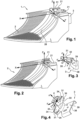
- FIG. 1 represents a lighting system 1 comprising an optical device 2 on which is directly mounted a module 3 supporting a light-emitting diode.
- the module 3 is mounted on the optical device 2 by means of two slides 21, forming an integral part of the optical device 2, and into which are inserted extensions 31 forming part of the module 3.
- the module 3 supporting the diode can also act as a heat sink and heat sink to dissipate the heat produced by the diode.
- the module is preferably made from a metal plate cut, stamped and bent into a desired shape.
- the optical device 2 is usually produced by injection of a thermosetting material or a plastic material, preferably thermoplastic, on which treatments are carried out to create surfaces acting as a mirror 28.
- the slides 21 are integral with the optical device 2 and are therefore positioned precisely in the frame of reference of the optical device 2.
- An orthonormal frame of reference OXYZ corresponding to the frame of reference of the optical device 2, makes it possible to precisely define the position in space of the characteristic points of this optical device such as the position of the surface of the mirror of general parabolic shape 28, or of the focal points etc.
- the light source placed on the module must therefore be positioned precisely in this reference frame, so as to optimize the operation of the lighting system.
- the ideal position of the light source has been placed at the geometric center O of the orthonormal reference frame.
- FIG. 2 represents the optical device 2 before assembly in which the slides 21 intended to receive the extensions 31 are released.
- FIGS. 3 and 4 represent perspective views of the module 3 before mounting on the optical device 2, according to two different positions of the axial reference o'x'y'z' which is centered on the high-power diode 4.
- the module 3 comprises two extensions 31 arranged laterally on either side of the module.
- Each extension 31 comprises a reference bearing face 32 and a contact face 33, opposite the reference support face and supporting contact points P, represented here by protrusions 34 projecting relative to the contact face 33 of the extension.
- the axes of the OXYZ and o'x'y'z' marks must therefore coincide very precisely so that the center of the diode 4 is placed very exactly at the geometric point O forming the center of the optical device 2.
- the OX axis here represents the general direction of introduction of the extensions 31 into the slides 21.
- the slide 21 comprises an inner reference face 22 and, arranged opposite said inner reference face, an inner guide face 24. These two faces make, according to the invention, between them a given angle "a" around the axis OY which is an axis parallel to the two faces 32 and 33 and perpendicular to the axis OX representing the general direction of introduction of the module into the slides 21 of the optical device 2.
- This angle "a” is between 1° and 10°, and preferably between 2° and 6°. Good experimental results have been obtained with an angle of 3°.
- This angular value conventionally called the draft angle, allows, among other things, easier demolding of the optical device 2.
- the section of extension 31 shown in the Figure 6 illustrates the case of an extension 31 whose contact face 33 comprises at least first and second contact points, the first contact point P 1 being arranged before the second contact point P 2 on the contact face in the direction of introduction (o'x'). These first and second contact points are formed, in the case of the Figure 6 , by two protrusions 34 offset from each other in the direction of the axis o'x'
- FIG. 7 represents the extension 31, once it has been introduced into the slide 21.
- the reference bearing face 32 of the extension 31 is in perfect contact with the reference inner face 22 of the slide.
- the protrusions 34 bear on the inner guide face 24 via the contact points P.
- the protuberance may have a hemispherical shape; in which case, the support between the protuberance and the inner guide face 24 is reduced to a quasi-point contact. It is also possible to produce protuberances having a substantially cylindrical shape whose generatrices are oriented in the direction o'y' perpendicular to the insertion direction o'x'; in which case, the contacts between the protuberance and the inner guide face 24 guide 24 of the slide are established along a ridge line forming a quasi-linear contact. These shapes have the advantage of being easily achievable by stamping the extensions 31, when the module is made from a metal sheet, but are not limiting.
- the extension 31 has a different thickness e at each contact point P, this thickness being measured normally at the reference bearing face 32, between said contact point P and the reference bearing face 32.
- the thickness e 1 of the extension 31 at the first contact point P 1 is less than the thickness e 2 of the extension at the second contact point P 2 .
- the protrusions 34 are intended to force the reference bearing face 32 of the extension 31 to come into contact with the reference inner face 22 of the slide, overcoming the irregularities in shape of the inner sliding face 24 and the contact face 33 of the extension. Their number is therefore not limiting.
- the material, preferably metallic, from which the module 3 is formed has a much higher hardness than the thermoplastic material forming the optical device 2 and the slide 21.
- the contact surface between the protrusion 34 and the inner guide face 24 being reduced, the protrusion elastically deforms the guide face locally around the point of contact, which increases the pressure force between the two reference faces 22 and 32.
- Elastic deformation here means that the deformation is reversible, and that the inner guide face 24 of the slide fully returns to its initial shape when the module 3 is removed from the lighting device.
- the designer of the lighting device is free to choose the shape and material of the slide 21 or the protrusions 34 of the module so that they undergo the desired elastic deformations, and to choose which of these two elements deforms the least.
- the shape of the slides 21 can also be subject to variations.
- the slides illustrated in the figures have a lateral opening in the plane formed by the axes OXZ.
- the orientation of the extensions 31 is then modified accordingly.
- the internal reference face 22 of the slide can be located in an equivalent manner in an upper or lower position along the direction OZ.
- the invention also provides second reference means, making it possible to block the movements of the module 3 relative to the optical device 2 in the general direction of introduction OX.
- These second reference means are formed by a second reference face (23, 29) carried by the optical device 2, which is perpendicular to the axis OX, and a second reference element (35, 39) carried by the module 3 and coming into abutment against said second reference face.
- the second reference face may be supported for example by a wall 25 of the slide 21 connecting the inner reference face 22 and the inner guide face 24, and the inner face 23 of which, acting as a second reference face, is intended to come into abutment against second reference elements 35 arranged on the front part of the extensions 31, as illustrated in figures 3 , 5, 6 and 7 .
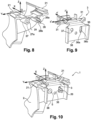
- FIG 8 allows to illustrate another embodiment, in which the second reference face 29 (see also the Figures 3 and 4 ) is carried by a projection 27 placed on the rear part of the optical device 2.
- the second reference face 29 is substantially perpendicular to the axis OX.
- the second reference element 39 is carried by the front face of a positioning wall 38 of the module 3 which is also perpendicular to the insertion axis OX. Once the module is mounted in the slide 21, the second reference element 39 comes into abutment against the second reference face 29 of the optical device 2.
- the projection 27 may usefully comprise a fixing orifice 27a intended to cooperate with a fixing orifice 37 made in the positioning wall 38 of the module 3.
- the fixing orifice 37 of the module 3 may have the general shape of a round hole.
- a guide means 26 installed on the optical device 2, and intended to cooperate with a guide orifice 36 placed on the module.
- the guide orifice 36 has a substantially oblong shape in the direction of the axis OZ, so as not to interfere with the adjustment in this direction of the internal reference face 22 of the slide with the reference bearing face 32 of the extension 31.
- the guide means 26 may have the shape of a tab, of circular section (not shown), the longitudinal direction of which is oriented along the axis OX, and which is of sufficient length in the direction of the axis OX to penetrate, during the assembly operation, into the guide orifice 36.
- the guide means (26, 36) and fixing means (27a, 37, 5) can also act as a foolproof device when the module 3 must, for example, be assembled on optical devices 2 having distinct photometric lighting functions of the right/left and/or low/high beam type.
- the fixing orifice 37 and the guide orifice 36 are then arranged according to a first pair of respective positions on the module 3 when the optical device 2 is intended to perform a first photometric function, such as a dipped-beam type lighting function, and the fixing orifice 37 and the guide orifice 36 are arranged according to a second pair of respective positions on the module 3 when the optical device 2 is intended to perform a second photometric function, such as a main-beam lighting function.
- a first photometric function such as a dipped-beam type lighting function
- a second photometric function such as a main-beam lighting function
- the optical device 2 is arranged to perform a single photometric function chosen from the first and second photometric functions.
- substantially identical modules 3 differing only in the respective position of the guide orifices 36 and the fixing orifices 37, on optical devices 2 having different photometric functions, and on which the positions of the guide means 26 and of the fixing orifice 27a are adapted accordingly.
- the fixing orifice 37 is positioned according to a first position on the module 3 and the guide orifice 36 is positioned according to a second position on the module 3, when the optical device 2 is intended to perform the first photometric function. And the fixing orifice 37 is positioned according to said second position on the module 3, and the guide orifice 36 is positioned according to said first position on the module 3 when the optical device 2 is intended to perform the second photometric function.
- the fixing orifice 27a and the guide means 26 of the optical device 2 are arranged according to the first pair of respective positions when the optical device 2 is intended to carry out the first photometric function, and the fixing orifice 27a and the guide means 26 of the optical device 2 are arranged according to the second pair of respective positions when the optical device 2 is intended to carry out the second photometric function.
- the embodiment of the keying device as detailed above is not limiting, and can be the subject of numerous variants in which the means of guidance and fixing means at well-defined locations to allow the assembly of standard elements slightly modified according to their destination, here modules supporting a diode, on organs ensuring different functions, here optical devices ensuring distinct photometric functions.
- the lighting system according to the invention may finally comprise third reference means making it possible to block the movement of the module relative to the optical device along the OY axis.
- These third reference means can usefully be arranged on the guide means 26, carried by the optical device 2.
- the guide means comprise, as illustrated in figures 8 and 9 , lateral wings 26a and 26b bearing against the lateral edges 36a and 36b, in the direction o'y', of the guide orifice 36.
- the third reference means can be formed by a third slide.
- the optical device then comprises three slides 21 each oriented along the OX axis, two being coplanar and the third slide being located in a plane substantially perpendicular to the first two slides.
- the module then comprises a third extension 31 intended to collaborate with the third slide 21. In this latter configuration, it is necessary to slightly widen the fixing orifice 37 and the guide orifice 36 in the OY direction so as to leave a clearance allowing the adjustment of the position of the module 3 along the OY direction.
- the assembly of the module 3 on the optical device 2 is done in an extremely simple manner, by introducing, in the direction OX, the guide means 26 into the guide orifice 36 so as to make the extensions 31 penetrate into the slides 21.
- This insertion movement is interrupted when the second reference element respectively 35, 39 comes into abutment against the second reference face respectively 23, 29.
- the screw 5 makes it possible to block the assembly in the two directions of the axis OX.
- the assembly and disassembly of the module 3 supporting the light source 4 can be done easily, thus facilitating any interventions to be carried out on the lighting system as part of vehicle maintenance.
- the light source 4 is then perfectly positioned at the center O of the optical device 2, and all movements of the module 3 along and around the axes OX, OY and OZ are prohibited.
Landscapes
- Engineering & Computer Science (AREA)
- General Engineering & Computer Science (AREA)
- Physics & Mathematics (AREA)
- Microelectronics & Electronic Packaging (AREA)
- Optics & Photonics (AREA)
- Non-Portable Lighting Devices Or Systems Thereof (AREA)
- Optical Couplings Of Light Guides (AREA)
Claims (9)
- Leuchtvorrichtung (1), insbesondere zur Beleuchtung und/oder zur Signalisierung, für ein Fahrzeug, umfassend eine optische Vorrichtung (2), ein Modul (3) und eine Lichtquelle (4), die auf dem Modul (3) angeordnet ist, das an der optischen Vorrichtung (2) angebracht ist, wobei die optische Vorrichtung (2) und das Modul (3) erste Referenzmittel umfassen, die Folgendes beinhalten:- mindestens eine Gleitführung (21), die auf der optischen Vorrichtung (2) montiert ist, wobei die Gleitführung (21) eine Referenzinnenfläche (22) umfasst, die gegenüber einer Führungsinnenfläche (24) platziert ist, und- mindestens eine Erweiterung (31), die sich von dem Modul erstreckt, wobei die Erweiterung eine Referenzanlagefläche (32) umfasst, die zu einer Kontaktfläche (33) entgegengesetzt ist, wobei die Kontaktfläche (33) mindestens einen ersten (P1) und einen zweiten Kontaktpunkt (P2) beinhaltet,wobei die Kontaktfläche (33) so eingerichtet ist, dass, wenn die Erweiterung (31) gemäß einer Einführungsrichtung (OX) in die Gleitführung (21) eingeführt ist, die Kontaktfläche (33) mit den Kontaktpunkten (P1, P2) an der Führungsinnenfläche (24) anliegt und dass, lokal im Bereich des Kontaktpunkts, sich die Gleitführung (21) und/oder die Erweiterung (31) elastisch verformen, wobei die Kontaktpunkte (P1, P2) auf mehreren Vorsprüngen (34) angeordnet sind, die sich von der Kontaktfläche (33) vorspringend erstrecken,wobei die Referenzanlagefläche (32) des Moduls an der Referenzinnenfläche (22) der Gleitführung zur Anlage gebracht wird,dadurch gekennzeichnet, dass der erste Kontaktpunkt (P1) gemäß der Einführungsrichtung (OX) vor dem zweiten Kontaktpunkt (P2) auf der Kontaktfläche (33) angeordnet ist,dass die Referenzinnenfläche (22) und die Führungsinnenfläche (24) der Gleitführung (2) zwischen sich einen gegebenen Winkel (a) um eine Achse (OY) bilden, welche zu der Referenzinnenfläche (22) und der Führungsinnenfläche (24) der Gleitführung (2) parallel und zu der Einführungsrichtung (OX) der Erweiterung (31) in die Gleitführung (21) im Wesentlichen senkrecht ist, wobei der zwischen der Referenzinnenfläche (22) und der Führungsinnenfläche (24) der Gleitführung gebildete Winkel zwischen 1° und 10° beträgt und vorzugsweise zwischen 2° und 6° beträgt,dass die Kontaktpunkte (P) in einer Ausrichtungsebene (L) liegen, die mit der Referenzanlagefläche (32) einen Winkel (a) um eine Achse (oy') bildet, welche zu der Referenzanlagefläche (32) und zu der Ausrichtungsebene (L) parallel und zu der Einführungsrichtung (o'x') der Erweiterung (31) in die Gleitführung (21) im Wesentlichen senkrecht ist,dass der Winkel (a), den die Ausrichtungsebene (L) und die Referenzanlagefläche (32) zwischen sich einschließen, im Wesentlichen gleich dem Winkel ist, der durch die Referenzinnenfläche (22) und die Führungsinnenfläche (24) der Gleitführung (2) gebildet wird, unddass das Modul (3) zwei Erweiterungen (31) beinhaltet, die sich seitlich zu beiden Seiten des Moduls (3) erstrecken und die in zwei Gleitführungen (21), die auf der optischen Vorrichtung (2) einander gegenüberliegend angeordnet sind, eingeführt werden.
- Leuchtvorrichtung (1) nach Anspruch 1, wobei die Erweiterung (31) im Bereich jedes Kontaktpunkts (P) eine unterschiedliche Dicke aufweist, wobei diese Dicke senkrecht zu der Referenzanlagefläche (32) zwischen dem Kontaktpunkt (P) und der Referenzanlagefläche (32) gemessen wird, wobei die Dicke der Erweiterung im Bereich des ersten Kontaktpunkts (P1) größer ist als die Dicke der Erweiterung im Bereich des zweiten Kontaktpunkts (P2).
- Leuchtvorrichtung (1) nach einem der vorhergehenden Ansprüche, wobei mindestens ein Vorsprung (34) im Wesentlichen halbkugelförmig ist, sodass der Vorsprung (34) durch einen quasi punktuellen Kontakt (P) auf der Führungsinnenfläche (24) der Gleitführung (21) aufliegt.
- Leuchtvorrichtung (1) nach einem der vorhergehenden Ansprüche, wobei mindestens ein Vorsprung (34) zylinderförmig ist, sodass der Vorsprung (34) durch einen quasi linearen Kontakt auf der Führungsinnenfläche (24) der Gleitführung (21) aufliegt.
- Leuchtvorrichtung (1) nach einem der Ansprüche 1 bis 4, beinhaltend zweite Referenzmittel, die durch das Modul (3) und die optische Vorrichtung (2) getragen werden und die es gestatten, die Bewegungen des Moduls (3) in Bezug auf die optische Vorrichtung (2) entlang der Einführungsrichtung (OX) zu blockieren, und die eine zweite Referenzfläche (23, 29) beinhalten, gegen die ein zweites Referenzelement (35, 39) in Anschlag kommt, wenn die Erweiterung (31) des Moduls (3) in die Gleitführung (21) eingeführt wird.
- Leuchtvorrichtung (1) nach Anspruch 5, wobei die zweite Referenzfläche durch eine Innenfläche (23) der Gleitführung (21) gebildet wird und wobei das zweite Referenzelement durch eine Vorderkante (35) der Erweiterung (31) gebildet wird.
- Leuchtvorrichtung (1) nach Anspruch 5, wobei die zweite Referenzfläche durch eine Fläche (29) gebildet wird, die sich auf einer Projektion (27) der optischen Vorrichtung (2) befindet, und wobei das zweite Referenzelement durch eine Fläche (39) einer Positionierungswand (38) des Moduls (3) gebildet wird, die zu der Einführungsrichtung (OX) im Wesentlichen senkrecht ist.
- Leuchtvorrichtung (1) nach einem der Ansprüche 1 bis 7, beinhaltend dritte Referenzmittel (26, 36), die durch das Modul (3) und die optische Vorrichtung (2) getragen werden und die es gestatten, die Bewegung des Moduls (3) in Bezug auf die optische Vorrichtung (2) entlang einer Richtung (OY) zu blockieren, welche zu der Referenzinnenfläche (22) und der Führungsinnenfläche (24) der Gleitführung (21) parallel und zu der Einführungsrichtung (OX) der Erweiterung (31) in die Gleitführung (21) im Wesentlichen senkrecht ist.
- Leuchtvorrichtung (1) nach Anspruch 8, wobei die dritten Referenzmittel durch Führungsmittel (26) der optischen Vorrichtung (2) und durch eine Führungsöffnung (36) des Moduls (3) gebildet werden.
Applications Claiming Priority (2)
| Application Number | Priority Date | Filing Date | Title |
|---|---|---|---|
| FR1459306A FR3026360B1 (fr) | 2014-09-30 | 2014-09-30 | Dispositif de positionnement sur un dispositif optique d'un module comportant une source lumineuse |
| PCT/EP2015/072073 WO2016050625A1 (fr) | 2014-09-30 | 2015-09-25 | Dispositif de positionnement sur un dispositif optique d'un module comportant une source lumineuse |
Publications (2)
| Publication Number | Publication Date |
|---|---|
| EP3201517A1 EP3201517A1 (de) | 2017-08-09 |
| EP3201517B1 true EP3201517B1 (de) | 2025-04-09 |
Family
ID=52345287
Family Applications (1)
| Application Number | Title | Priority Date | Filing Date |
|---|---|---|---|
| EP15771567.3A Active EP3201517B1 (de) | 2014-09-30 | 2015-09-25 | Vorrichtung zur positionierung eines moduls mit einer lichtquelle auf einer optischen vorrichtung |
Country Status (5)
| Country | Link |
|---|---|
| US (1) | US10605423B2 (de) |
| EP (1) | EP3201517B1 (de) |
| CN (1) | CN106796009B (de) |
| FR (1) | FR3026360B1 (de) |
| WO (1) | WO2016050625A1 (de) |
Families Citing this family (10)
| Publication number | Priority date | Publication date | Assignee | Title |
|---|---|---|---|---|
| FR3056682B1 (fr) | 2016-09-27 | 2020-10-16 | Valeo Vision | Support de source de lumiere avec un element de referencement s'etendant selon deux axes |
| DE102017104841A1 (de) * | 2017-03-08 | 2018-09-13 | HELLA GmbH & Co. KGaA | Beleuchtungsvorrichtung für Fahrzeuge sowie Montageverfahren |
| DE102018105753A1 (de) * | 2018-03-13 | 2019-09-19 | Automotive Lighting Reutlingen Gmbh | Fahrzeugscheinwerfer |
| CN109404855A (zh) * | 2018-11-28 | 2019-03-01 | 马瑞利汽车零部件(芜湖)有限公司 | 汽车多腔反射式远近光前照灯的系统 |
| CN113625413A (zh) * | 2021-08-02 | 2021-11-09 | 嘉兴旭锐电子科技有限公司 | 一种点定位的定位块及光学定位系统 |
| FR3136269B1 (fr) * | 2022-06-02 | 2024-11-22 | Psa Automobiles Sa | Ensemble d’éclairage pour projecteur de véhicule automobile |
| FR3141232B1 (fr) * | 2022-10-19 | 2024-09-06 | Psa Automobiles Sa | Bloc optique, pour véhicule, équipé d’un radiateur thermique |
| CN220108548U (zh) * | 2023-05-29 | 2023-11-28 | 市光法雷奥(佛山)汽车照明系统有限公司 | 散热器、照明装置和机动车辆 |
| DE102023135249A1 (de) * | 2023-12-14 | 2025-06-18 | Osram Gmbh | Leuchtvorrichtung umfassend ein haltemodul und ein lösbar befestigtes leuchtmodul |
| DE102024118169A1 (de) * | 2024-06-27 | 2025-12-31 | Osram Gmbh | Leuchtmodul mit verbesserter emv abschirmung |
Citations (2)
| Publication number | Priority date | Publication date | Assignee | Title |
|---|---|---|---|---|
| US20110051448A1 (en) * | 2009-09-03 | 2011-03-03 | Ryotaro Owada | Vehicle headlight |
| DE102010048594A1 (de) * | 2010-10-15 | 2012-04-19 | Hella Kgaa Hueck & Co. | Scheinwerfer für ein Fahrzeug mit einem LED-Hauptlichtmodul |
Family Cites Families (16)
| Publication number | Priority date | Publication date | Assignee | Title |
|---|---|---|---|---|
| DE3132709A1 (de) | 1981-08-19 | 1983-03-03 | Robert Bosch Gmbh, 7000 Stuttgart | Leuchte fuer fahrzeuge, insbesondere leuchte fuer kraftfahrzeuge |
| JP4350617B2 (ja) * | 2004-08-24 | 2009-10-21 | 株式会社小糸製作所 | 灯具 |
| JP2006302713A (ja) * | 2005-04-21 | 2006-11-02 | Koito Mfg Co Ltd | 車両用前照灯 |
| JP2007200697A (ja) * | 2006-01-26 | 2007-08-09 | Koito Mfg Co Ltd | 車輌用灯具 |
| JP4500273B2 (ja) * | 2006-01-31 | 2010-07-14 | 株式会社小糸製作所 | 車両用前照灯 |
| CN201273475Y (zh) * | 2008-10-16 | 2009-07-15 | 劦星企业有限公司 | 发光二极管灯泡结构 |
| DE102009052340A1 (de) | 2009-11-03 | 2011-05-05 | Automotive Lighting Reutlingen Gmbh | Leuchtdiodenmodul einer Kraftfahrzeugbeleuchtungseinrichtung, Kraftfahrzeugbeleuchtungseinrichtung und Verfahren zur Befestigung einer Leuchtdiode in dem Leuchtdiodenmodul |
| JP5706702B2 (ja) * | 2011-02-03 | 2015-04-22 | 株式会社小糸製作所 | 車輌用前照灯 |
| GB2487912B (en) | 2011-02-07 | 2014-11-12 | Collingwood Lighting Ltd | Lighting unit |
| EP2587121A1 (de) * | 2011-10-28 | 2013-05-01 | Hella KGaA Hueck & Co. | LED-Beleuchtung mit auf der Leiterplatte befestigten Reflektor |
| CN202719520U (zh) * | 2012-01-04 | 2013-02-06 | 江苏文光车辆附件有限公司 | 一种led模组作为汽车灯具光源的灯具 |
| KR20140003175A (ko) * | 2012-06-29 | 2014-01-09 | 양기해 | 신발 수용체, 신발 포장 용기 및 이를 포함하는 신발 수납장 |
| CN103367033A (zh) * | 2013-07-10 | 2013-10-23 | 新昌县富士精工科技有限公司 | 一种新型液位开关 |
| FR3049041B1 (fr) * | 2016-03-21 | 2019-04-05 | Valeo Vision | Module lumineux comportant au moins une source lumineuse amovible |
| FR3055397B1 (fr) * | 2016-08-30 | 2021-04-30 | Valeo Vision | Module lumineux comportant au moins une source lumineuse amovible |
| FR3056682B1 (fr) * | 2016-09-27 | 2020-10-16 | Valeo Vision | Support de source de lumiere avec un element de referencement s'etendant selon deux axes |
-
2014
- 2014-09-30 FR FR1459306A patent/FR3026360B1/fr active Active
-
2015
- 2015-09-25 WO PCT/EP2015/072073 patent/WO2016050625A1/fr not_active Ceased
- 2015-09-25 CN CN201580053126.8A patent/CN106796009B/zh active Active
- 2015-09-25 EP EP15771567.3A patent/EP3201517B1/de active Active
- 2015-09-25 US US15/515,190 patent/US10605423B2/en active Active
Patent Citations (2)
| Publication number | Priority date | Publication date | Assignee | Title |
|---|---|---|---|---|
| US20110051448A1 (en) * | 2009-09-03 | 2011-03-03 | Ryotaro Owada | Vehicle headlight |
| DE102010048594A1 (de) * | 2010-10-15 | 2012-04-19 | Hella Kgaa Hueck & Co. | Scheinwerfer für ein Fahrzeug mit einem LED-Hauptlichtmodul |
Also Published As
| Publication number | Publication date |
|---|---|
| WO2016050625A1 (fr) | 2016-04-07 |
| CN106796009B (zh) | 2020-05-22 |
| EP3201517A1 (de) | 2017-08-09 |
| FR3026360B1 (fr) | 2018-03-23 |
| CN106796009A (zh) | 2017-05-31 |
| US20170211768A1 (en) | 2017-07-27 |
| US10605423B2 (en) | 2020-03-31 |
| FR3026360A1 (fr) | 2016-04-01 |
Similar Documents
| Publication | Publication Date | Title |
|---|---|---|
| EP3201517B1 (de) | Vorrichtung zur positionierung eines moduls mit einer lichtquelle auf einer optischen vorrichtung | |
| EP2926052B1 (de) | Beleuchtungs- und/oder signalisierungsvorrichtung für kraftfahrzeuge | |
| EP3857116B1 (de) | Lichtmodul für fahrzeug mit einem referenzierungsstift mit einem biegsamen teil und einem steifen teil | |
| EP3299710B1 (de) | Leuchtmodul und leuchtvorrichtung für kraftfahrzeug, das ein solches leuchtmodul umfasst | |
| EP3884206B1 (de) | Multifunktionales lichtmodul mit zwei flachen lichtleitern | |
| WO2014083123A1 (fr) | Dispositif d'éclairage et/ou de signalisation pour véhicule automobile | |
| EP2966342B1 (de) | Beleuchtungsmodul eines projektionsscheinwerfers für ein kraftfahrzeug | |
| EP3299701B1 (de) | Halterung für lichtquelle mit einem bezugselement, das sich über zwei achsen erstreckt | |
| EP3104074B1 (de) | Positionierunganordnung eines led- leuchtmittelträgers auf einem trägerelement und leuchtmodul für eine leuchte oder signalleuchte die eine solche anordnung trägt | |
| WO2020058289A1 (fr) | Systeme lumineux pour dispositif d'eclairage et/ou de signalisation d'un vehicule automobile | |
| FR3030685A1 (fr) | Dispositif d'eclairage et/ou de signalisation comportant un guide de lumiere | |
| EP3507543B1 (de) | Medizinische beleuchtungsvorrichtung mit leds, die durch in einer leiterplatte vorgeschnittene laschen ausgerichtet sind | |
| WO2016050624A1 (fr) | Dispositif lumineux de vehicule avec des moyens de positionnement d'une carte electronique | |
| EP2966344A1 (de) | Optisches modul mit linse für kfz-scheinwerfer | |
| EP3357751A1 (de) | Optisches modul für kraftfahrzeug, und positionsverriegelung einer komponente des moduls mithilfe eines elastisch verformbaren einspannelements | |
| FR2950129A1 (fr) | Dispositif d'eclairage et /ou de signalisation pour vehicule automobile. | |
| EP3239598B1 (de) | Drehbares leuchtmodul | |
| FR3056698B1 (fr) | Module lumineux pour vehicule automobile | |
| WO2023031072A1 (fr) | Module d'émission de lumière comprenant un support destiné à dissiper de la chaleur | |
| EP3492806B1 (de) | Vorrichtung zur beleuchtung und/oder signalisierung für kraftfahrzeug | |
| FR3022980A1 (fr) | Module optique a lentille pour vehicule automobile | |
| EP3486554B1 (de) | Lichtmodul für fahrzeugscheinwerfer | |
| FR3088869A1 (fr) | Dispositif de pré-positionnement et de maintien d’un élément sur un boitier | |
| EP3422071B1 (de) | Fahrzeugbeleuchtungsvorrichtung und/oder fahrzeugsignalvorrichtung | |
| FR3038693A1 (fr) | Module lumineux pour projecteur de vehicule automobile |
Legal Events
| Date | Code | Title | Description |
|---|---|---|---|
| STAA | Information on the status of an ep patent application or granted ep patent |
Free format text: STATUS: THE INTERNATIONAL PUBLICATION HAS BEEN MADE |
|
| PUAI | Public reference made under article 153(3) epc to a published international application that has entered the european phase |
Free format text: ORIGINAL CODE: 0009012 |
|
| STAA | Information on the status of an ep patent application or granted ep patent |
Free format text: STATUS: REQUEST FOR EXAMINATION WAS MADE |
|
| 17P | Request for examination filed |
Effective date: 20170323 |
|
| AK | Designated contracting states |
Kind code of ref document: A1 Designated state(s): AL AT BE BG CH CY CZ DE DK EE ES FI FR GB GR HR HU IE IS IT LI LT LU LV MC MK MT NL NO PL PT RO RS SE SI SK SM TR |
|
| AX | Request for extension of the european patent |
Extension state: BA ME |
|
| DAV | Request for validation of the european patent (deleted) | ||
| DAX | Request for extension of the european patent (deleted) | ||
| STAA | Information on the status of an ep patent application or granted ep patent |
Free format text: STATUS: EXAMINATION IS IN PROGRESS |
|
| 17Q | First examination report despatched |
Effective date: 20200417 |
|
| P01 | Opt-out of the competence of the unified patent court (upc) registered |
Effective date: 20230528 |
|
| REG | Reference to a national code |
Ref country code: DE Ref legal event code: R079 Free format text: PREVIOUS MAIN CLASS: F21S0008100000 Ipc: F21S0041190000 Ref country code: DE Ref legal event code: R079 Ref document number: 602015091406 Country of ref document: DE Free format text: PREVIOUS MAIN CLASS: F21S0008100000 Ipc: F21S0041190000 |
|
| RIC1 | Information provided on ipc code assigned before grant |
Ipc: F21S 43/19 20180101ALI20230818BHEP Ipc: F21S 43/14 20180101ALI20230818BHEP Ipc: F21S 41/148 20180101ALI20230818BHEP Ipc: F21S 41/19 20180101AFI20230818BHEP |
|
| GRAP | Despatch of communication of intention to grant a patent |
Free format text: ORIGINAL CODE: EPIDOSNIGR1 |
|
| STAA | Information on the status of an ep patent application or granted ep patent |
Free format text: STATUS: GRANT OF PATENT IS INTENDED |
|
| INTG | Intention to grant announced |
Effective date: 20240430 |
|
| GRAJ | Information related to disapproval of communication of intention to grant by the applicant or resumption of examination proceedings by the epo deleted |
Free format text: ORIGINAL CODE: EPIDOSDIGR1 |
|
| STAA | Information on the status of an ep patent application or granted ep patent |
Free format text: STATUS: EXAMINATION IS IN PROGRESS |
|
| INTC | Intention to grant announced (deleted) | ||
| GRAP | Despatch of communication of intention to grant a patent |
Free format text: ORIGINAL CODE: EPIDOSNIGR1 |
|
| STAA | Information on the status of an ep patent application or granted ep patent |
Free format text: STATUS: GRANT OF PATENT IS INTENDED |
|
| INTG | Intention to grant announced |
Effective date: 20241104 |
|
| GRAS | Grant fee paid |
Free format text: ORIGINAL CODE: EPIDOSNIGR3 |
|
| GRAA | (expected) grant |
Free format text: ORIGINAL CODE: 0009210 |
|
| STAA | Information on the status of an ep patent application or granted ep patent |
Free format text: STATUS: THE PATENT HAS BEEN GRANTED |
|
| AK | Designated contracting states |
Kind code of ref document: B1 Designated state(s): AL AT BE BG CH CY CZ DE DK EE ES FI FR GB GR HR HU IE IS IT LI LT LU LV MC MK MT NL NO PL PT RO RS SE SI SK SM TR |
|
| REG | Reference to a national code |
Ref country code: GB Ref legal event code: FG4D Free format text: NOT ENGLISH |
|
| REG | Reference to a national code |
Ref country code: CH Ref legal event code: EP |
|
| REG | Reference to a national code |
Ref country code: DE Ref legal event code: R096 Ref document number: 602015091406 Country of ref document: DE |
|
| REG | Reference to a national code |
Ref country code: IE Ref legal event code: FG4D Free format text: LANGUAGE OF EP DOCUMENT: FRENCH |
|
| REG | Reference to a national code |
Ref country code: NL Ref legal event code: MP Effective date: 20250409 |
|
| PG25 | Lapsed in a contracting state [announced via postgrant information from national office to epo] |
Ref country code: NL Free format text: LAPSE BECAUSE OF FAILURE TO SUBMIT A TRANSLATION OF THE DESCRIPTION OR TO PAY THE FEE WITHIN THE PRESCRIBED TIME-LIMIT Effective date: 20250409 |
|
| REG | Reference to a national code |
Ref country code: AT Ref legal event code: MK05 Ref document number: 1783794 Country of ref document: AT Kind code of ref document: T Effective date: 20250409 |
|
| PG25 | Lapsed in a contracting state [announced via postgrant information from national office to epo] |
Ref country code: PT Free format text: LAPSE BECAUSE OF FAILURE TO SUBMIT A TRANSLATION OF THE DESCRIPTION OR TO PAY THE FEE WITHIN THE PRESCRIBED TIME-LIMIT Effective date: 20250811 Ref country code: FI Free format text: LAPSE BECAUSE OF FAILURE TO SUBMIT A TRANSLATION OF THE DESCRIPTION OR TO PAY THE FEE WITHIN THE PRESCRIBED TIME-LIMIT Effective date: 20250409 Ref country code: ES Free format text: LAPSE BECAUSE OF FAILURE TO SUBMIT A TRANSLATION OF THE DESCRIPTION OR TO PAY THE FEE WITHIN THE PRESCRIBED TIME-LIMIT Effective date: 20250409 |
|
| PGFP | Annual fee paid to national office [announced via postgrant information from national office to epo] |
Ref country code: DE Payment date: 20250916 Year of fee payment: 11 |
|
| REG | Reference to a national code |
Ref country code: LT Ref legal event code: MG9D |
|
| PG25 | Lapsed in a contracting state [announced via postgrant information from national office to epo] |
Ref country code: NO Free format text: LAPSE BECAUSE OF FAILURE TO SUBMIT A TRANSLATION OF THE DESCRIPTION OR TO PAY THE FEE WITHIN THE PRESCRIBED TIME-LIMIT Effective date: 20250709 Ref country code: GR Free format text: LAPSE BECAUSE OF FAILURE TO SUBMIT A TRANSLATION OF THE DESCRIPTION OR TO PAY THE FEE WITHIN THE PRESCRIBED TIME-LIMIT Effective date: 20250710 |
|
| PG25 | Lapsed in a contracting state [announced via postgrant information from national office to epo] |
Ref country code: PL Free format text: LAPSE BECAUSE OF FAILURE TO SUBMIT A TRANSLATION OF THE DESCRIPTION OR TO PAY THE FEE WITHIN THE PRESCRIBED TIME-LIMIT Effective date: 20250409 |
|
| PG25 | Lapsed in a contracting state [announced via postgrant information from national office to epo] |
Ref country code: BG Free format text: LAPSE BECAUSE OF FAILURE TO SUBMIT A TRANSLATION OF THE DESCRIPTION OR TO PAY THE FEE WITHIN THE PRESCRIBED TIME-LIMIT Effective date: 20250409 |
|
| PG25 | Lapsed in a contracting state [announced via postgrant information from national office to epo] |
Ref country code: HR Free format text: LAPSE BECAUSE OF FAILURE TO SUBMIT A TRANSLATION OF THE DESCRIPTION OR TO PAY THE FEE WITHIN THE PRESCRIBED TIME-LIMIT Effective date: 20250409 |
|
| PG25 | Lapsed in a contracting state [announced via postgrant information from national office to epo] |
Ref country code: AT Free format text: LAPSE BECAUSE OF FAILURE TO SUBMIT A TRANSLATION OF THE DESCRIPTION OR TO PAY THE FEE WITHIN THE PRESCRIBED TIME-LIMIT Effective date: 20250409 |
|
| PGFP | Annual fee paid to national office [announced via postgrant information from national office to epo] |
Ref country code: FR Payment date: 20250929 Year of fee payment: 11 |
|
| PG25 | Lapsed in a contracting state [announced via postgrant information from national office to epo] |
Ref country code: RS Free format text: LAPSE BECAUSE OF FAILURE TO SUBMIT A TRANSLATION OF THE DESCRIPTION OR TO PAY THE FEE WITHIN THE PRESCRIBED TIME-LIMIT Effective date: 20250709 |
|
| PG25 | Lapsed in a contracting state [announced via postgrant information from national office to epo] |
Ref country code: IS Free format text: LAPSE BECAUSE OF FAILURE TO SUBMIT A TRANSLATION OF THE DESCRIPTION OR TO PAY THE FEE WITHIN THE PRESCRIBED TIME-LIMIT Effective date: 20250809 |
|
| PG25 | Lapsed in a contracting state [announced via postgrant information from national office to epo] |
Ref country code: LV Free format text: LAPSE BECAUSE OF FAILURE TO SUBMIT A TRANSLATION OF THE DESCRIPTION OR TO PAY THE FEE WITHIN THE PRESCRIBED TIME-LIMIT Effective date: 20250409 |
|
| REG | Reference to a national code |
Ref country code: DE Ref legal event code: R097 Ref document number: 602015091406 Country of ref document: DE |
|
| PG25 | Lapsed in a contracting state [announced via postgrant information from national office to epo] |
Ref country code: DK Free format text: LAPSE BECAUSE OF FAILURE TO SUBMIT A TRANSLATION OF THE DESCRIPTION OR TO PAY THE FEE WITHIN THE PRESCRIBED TIME-LIMIT Effective date: 20250409 Ref country code: SM Free format text: LAPSE BECAUSE OF FAILURE TO SUBMIT A TRANSLATION OF THE DESCRIPTION OR TO PAY THE FEE WITHIN THE PRESCRIBED TIME-LIMIT Effective date: 20250409 |
|
| PG25 | Lapsed in a contracting state [announced via postgrant information from national office to epo] |
Ref country code: CZ Free format text: LAPSE BECAUSE OF FAILURE TO SUBMIT A TRANSLATION OF THE DESCRIPTION OR TO PAY THE FEE WITHIN THE PRESCRIBED TIME-LIMIT Effective date: 20250409 |
|
| PG25 | Lapsed in a contracting state [announced via postgrant information from national office to epo] |
Ref country code: EE Free format text: LAPSE BECAUSE OF FAILURE TO SUBMIT A TRANSLATION OF THE DESCRIPTION OR TO PAY THE FEE WITHIN THE PRESCRIBED TIME-LIMIT Effective date: 20250409 |
|
| PG25 | Lapsed in a contracting state [announced via postgrant information from national office to epo] |
Ref country code: SK Free format text: LAPSE BECAUSE OF FAILURE TO SUBMIT A TRANSLATION OF THE DESCRIPTION OR TO PAY THE FEE WITHIN THE PRESCRIBED TIME-LIMIT Effective date: 20250409 Ref country code: RO Free format text: LAPSE BECAUSE OF FAILURE TO SUBMIT A TRANSLATION OF THE DESCRIPTION OR TO PAY THE FEE WITHIN THE PRESCRIBED TIME-LIMIT Effective date: 20250409 |
|
| PG25 | Lapsed in a contracting state [announced via postgrant information from national office to epo] |
Ref country code: IT Free format text: LAPSE BECAUSE OF FAILURE TO SUBMIT A TRANSLATION OF THE DESCRIPTION OR TO PAY THE FEE WITHIN THE PRESCRIBED TIME-LIMIT Effective date: 20250409 |
|
| PLBE | No opposition filed within time limit |
Free format text: ORIGINAL CODE: 0009261 |
|
| STAA | Information on the status of an ep patent application or granted ep patent |
Free format text: STATUS: NO OPPOSITION FILED WITHIN TIME LIMIT |
|
| REG | Reference to a national code |
Ref country code: CH Ref legal event code: L10 Free format text: ST27 STATUS EVENT CODE: U-0-0-L10-L00 (AS PROVIDED BY THE NATIONAL OFFICE) Effective date: 20260218 |
|
| 26N | No opposition filed |
Effective date: 20260112 |