EP3200973B1 - Controlling temperature in an apparatus for generating a three-dimensional object - Google Patents
Controlling temperature in an apparatus for generating a three-dimensional object Download PDFInfo
- Publication number
- EP3200973B1 EP3200973B1 EP14781164.0A EP14781164A EP3200973B1 EP 3200973 B1 EP3200973 B1 EP 3200973B1 EP 14781164 A EP14781164 A EP 14781164A EP 3200973 B1 EP3200973 B1 EP 3200973B1
- Authority
- EP
- European Patent Office
- Prior art keywords
- temperature
- build material
- point
- calibrated
- melting point
- Prior art date
- Legal status (The legal status is an assumption and is not a legal conclusion. Google has not performed a legal analysis and makes no representation as to the accuracy of the status listed.)
- Active
Links
- 239000000463 material Substances 0.000 claims description 149
- 238000002844 melting Methods 0.000 claims description 62
- 230000008018 melting Effects 0.000 claims description 62
- 238000000034 method Methods 0.000 claims description 54
- 238000002425 crystallisation Methods 0.000 claims description 44
- 230000008025 crystallization Effects 0.000 claims description 44
- 238000012360 testing method Methods 0.000 claims description 26
- 230000008859 change Effects 0.000 claims description 24
- 238000012544 monitoring process Methods 0.000 claims description 24
- 238000000151 deposition Methods 0.000 claims description 16
- 230000003287 optical effect Effects 0.000 claims description 5
- 238000012545 processing Methods 0.000 claims description 5
- 239000003795 chemical substances by application Substances 0.000 description 57
- 230000008569 process Effects 0.000 description 14
- 239000010410 layer Substances 0.000 description 13
- 239000000843 powder Substances 0.000 description 13
- 238000004581 coalescence Methods 0.000 description 9
- 239000003607 modifier Substances 0.000 description 8
- 230000000007 visual effect Effects 0.000 description 5
- 230000000694 effects Effects 0.000 description 4
- 239000012530 fluid Substances 0.000 description 4
- 239000011236 particulate material Substances 0.000 description 4
- 239000002356 single layer Substances 0.000 description 3
- 230000002745 absorbent Effects 0.000 description 2
- 239000002250 absorbent Substances 0.000 description 2
- 230000008901 benefit Effects 0.000 description 2
- 238000001816 cooling Methods 0.000 description 2
- 230000007613 environmental effect Effects 0.000 description 2
- 230000004927 fusion Effects 0.000 description 2
- 238000010438 heat treatment Methods 0.000 description 2
- 239000000654 additive Substances 0.000 description 1
- 230000000996 additive effect Effects 0.000 description 1
- 230000032683 aging Effects 0.000 description 1
- 238000004458 analytical method Methods 0.000 description 1
- 238000009529 body temperature measurement Methods 0.000 description 1
- 230000001427 coherent effect Effects 0.000 description 1
- 238000011109 contamination Methods 0.000 description 1
- 230000001419 dependent effect Effects 0.000 description 1
- 238000013461 design Methods 0.000 description 1
- 239000008187 granular material Substances 0.000 description 1
- 238000004519 manufacturing process Methods 0.000 description 1
- 230000007246 mechanism Effects 0.000 description 1
- 238000010309 melting process Methods 0.000 description 1
- 238000012986 modification Methods 0.000 description 1
- 230000004048 modification Effects 0.000 description 1
- 230000005855 radiation Effects 0.000 description 1
- 230000004044 response Effects 0.000 description 1
- 230000035945 sensitivity Effects 0.000 description 1
- 238000005245 sintering Methods 0.000 description 1
- 239000007787 solid Substances 0.000 description 1
- 230000003746 surface roughness Effects 0.000 description 1
- 238000007794 visualization technique Methods 0.000 description 1
Images


Classifications
-
- B—PERFORMING OPERATIONS; TRANSPORTING
- B29—WORKING OF PLASTICS; WORKING OF SUBSTANCES IN A PLASTIC STATE IN GENERAL
- B29C—SHAPING OR JOINING OF PLASTICS; SHAPING OF MATERIAL IN A PLASTIC STATE, NOT OTHERWISE PROVIDED FOR; AFTER-TREATMENT OF THE SHAPED PRODUCTS, e.g. REPAIRING
- B29C35/00—Heating, cooling or curing, e.g. crosslinking or vulcanising; Apparatus therefor
- B29C35/02—Heating or curing, e.g. crosslinking or vulcanizing during moulding, e.g. in a mould
- B29C35/0288—Controlling heating or curing of polymers during moulding, e.g. by measuring temperatures or properties of the polymer and regulating the process
-
- B—PERFORMING OPERATIONS; TRANSPORTING
- B29—WORKING OF PLASTICS; WORKING OF SUBSTANCES IN A PLASTIC STATE IN GENERAL
- B29C—SHAPING OR JOINING OF PLASTICS; SHAPING OF MATERIAL IN A PLASTIC STATE, NOT OTHERWISE PROVIDED FOR; AFTER-TREATMENT OF THE SHAPED PRODUCTS, e.g. REPAIRING
- B29C64/00—Additive manufacturing, i.e. manufacturing of three-dimensional [3D] objects by additive deposition, additive agglomeration or additive layering, e.g. by 3D printing, stereolithography or selective laser sintering
- B29C64/10—Processes of additive manufacturing
- B29C64/165—Processes of additive manufacturing using a combination of solid and fluid materials, e.g. a powder selectively bound by a liquid binder, catalyst, inhibitor or energy absorber
-
- B—PERFORMING OPERATIONS; TRANSPORTING
- B29—WORKING OF PLASTICS; WORKING OF SUBSTANCES IN A PLASTIC STATE IN GENERAL
- B29C—SHAPING OR JOINING OF PLASTICS; SHAPING OF MATERIAL IN A PLASTIC STATE, NOT OTHERWISE PROVIDED FOR; AFTER-TREATMENT OF THE SHAPED PRODUCTS, e.g. REPAIRING
- B29C64/00—Additive manufacturing, i.e. manufacturing of three-dimensional [3D] objects by additive deposition, additive agglomeration or additive layering, e.g. by 3D printing, stereolithography or selective laser sintering
- B29C64/20—Apparatus for additive manufacturing; Details thereof or accessories therefor
- B29C64/264—Arrangements for irradiation
-
- B—PERFORMING OPERATIONS; TRANSPORTING
- B29—WORKING OF PLASTICS; WORKING OF SUBSTANCES IN A PLASTIC STATE IN GENERAL
- B29C—SHAPING OR JOINING OF PLASTICS; SHAPING OF MATERIAL IN A PLASTIC STATE, NOT OTHERWISE PROVIDED FOR; AFTER-TREATMENT OF THE SHAPED PRODUCTS, e.g. REPAIRING
- B29C64/00—Additive manufacturing, i.e. manufacturing of three-dimensional [3D] objects by additive deposition, additive agglomeration or additive layering, e.g. by 3D printing, stereolithography or selective laser sintering
- B29C64/30—Auxiliary operations or equipment
- B29C64/386—Data acquisition or data processing for additive manufacturing
- B29C64/393—Data acquisition or data processing for additive manufacturing for controlling or regulating additive manufacturing processes
-
- B—PERFORMING OPERATIONS; TRANSPORTING
- B33—ADDITIVE MANUFACTURING TECHNOLOGY
- B33Y—ADDITIVE MANUFACTURING, i.e. MANUFACTURING OF THREE-DIMENSIONAL [3-D] OBJECTS BY ADDITIVE DEPOSITION, ADDITIVE AGGLOMERATION OR ADDITIVE LAYERING, e.g. BY 3-D PRINTING, STEREOLITHOGRAPHY OR SELECTIVE LASER SINTERING
- B33Y10/00—Processes of additive manufacturing
-
- B—PERFORMING OPERATIONS; TRANSPORTING
- B33—ADDITIVE MANUFACTURING TECHNOLOGY
- B33Y—ADDITIVE MANUFACTURING, i.e. MANUFACTURING OF THREE-DIMENSIONAL [3-D] OBJECTS BY ADDITIVE DEPOSITION, ADDITIVE AGGLOMERATION OR ADDITIVE LAYERING, e.g. BY 3-D PRINTING, STEREOLITHOGRAPHY OR SELECTIVE LASER SINTERING
- B33Y30/00—Apparatus for additive manufacturing; Details thereof or accessories therefor
-
- B—PERFORMING OPERATIONS; TRANSPORTING
- B33—ADDITIVE MANUFACTURING TECHNOLOGY
- B33Y—ADDITIVE MANUFACTURING, i.e. MANUFACTURING OF THREE-DIMENSIONAL [3-D] OBJECTS BY ADDITIVE DEPOSITION, ADDITIVE AGGLOMERATION OR ADDITIVE LAYERING, e.g. BY 3-D PRINTING, STEREOLITHOGRAPHY OR SELECTIVE LASER SINTERING
- B33Y50/00—Data acquisition or data processing for additive manufacturing
- B33Y50/02—Data acquisition or data processing for additive manufacturing for controlling or regulating additive manufacturing processes
Definitions
- Additive manufacturing systems that generate three-dimensional objects on a layer-by-layer basis have been proposed as a potentially convenient way to produce three-dimensional objects.
- European Patent EP1296788 discloses a method for generating 3D objects that comprises a temperature calibration algorithm.
- a process of generating a tangible three-dimension object may comprise, for example, a series of steps which include forming a layer of build material, selectively delivering an agent (for example a coalescing agent and a coalescence modifier agent) to one or more portions of a surface of the layer of build material, and temporarily applying a predetermined level of energy to the layer of build material.
- the temporary application of energy may cause portions of the build material on which coalescing agent has been delivered or has penetrated to heat up above the melting point of the build material and to coalesce. Upon cooling, the portions which have coalesced become solid and form part of the three-dimensional object being generated.
- These steps are then repeated to form a three-dimensional object.
- Other steps and procedures may also be used with these steps for generating a three-dimensional object.
- coalescing agent and coalescence modifier agent can comprise fluids that may be delivered using any appropriate fluid delivery mechanism, also referred to as an agent distributor.
- agents are delivered in droplet form.
- a coalescence modifier agent may be used for a variety of purposes.
- a coalescence modifier agent may be delivered adjacent to where coalescing agent is delivered, for example to help reduce the effects of lateral coalescence bleed. This may be used, for example, to improve the definition or accuracy of object edges or surfaces, and/or to reduce surface roughness.
- coalescence modifier agent may be delivered interspersed with coalescing agent, which may be used to enable object properties to be modified.
- a build material is a powder-based build material.
- powder-based material is intended to encompass both dry and wet powder-based materials, particulate materials, and granular materials.
- the examples described herein are related to a method and apparatus for controlling temperature in an apparatus for generating a three-dimensional object, wherein at least one temperature point in a build process is calibrated, the temperature point comprising a melting point and/or a crystallization point in a build process.
- melting point means the temperature at which build material becomes a coherent mass, for example by sintering, melting, fusing or coalescing.
- a calibration test is performed to calibrate the at least one temperature point, the calibration test based on the build material that is to be used in generating a three-dimensional object.
- the calibration of at least one temperature point has the advantage of enabling a more accurate control of the temperature of the build material in relation to such calibrated temperature point(s), i.e. at a melting point and/or a crystallization point, when building a three-dimensional object or component.
- the build material e.g. powder or particulate material
- the build material may be heated and kept just below a fusing temperature and kept above the crystallization point of the build material.
- the crystallization and melting points can change substantially. It is noted that there can also be variability in sensors that are used to monitor temperature, or other system components which are used to generate a three-dimensional object.
- Figure 1 shows an example of an overview of a method of controlling temperature in an apparatus for generating a three-dimensional object which is described in greater detail below.
- the method comprises performing a calibration test on a sample of a build material that is to be used in generating a three-dimensional object, step 101. At least one temperature point is calibrated from the calibration test, step 103. In step 105, the at least one calibrated temperature point is used during subsequent temperature control of the apparatus.
- FIG. 2 shows an example of a method for performing the calibration test for calibrating at least one temperature point.
- the calibration test is used, to calibrate a crystallization point and/or a melting point that are to be used in a build process.
- the method comprises depositing coalescing agent on at least a portion of a build zone, step 201.
- the coalescing agent may comprise any material or fluid that is used to interact or coalesce with build material when exposed to an energy source.
- the coalescing agent may comprise an absorbent ink or other printing fluid.
- a coalescence modifier agent may also be deposited on or with the coalescing agent.
- step 203 build material is deposited over the coalescing agent.
- a layer of build material may be deposited over at least a part of the coalescing agent where a monitoring operation is to be performed.
- a single layer of build material is deposited on the coalescing agent.
- multiple layers of build material are deposited on the coalescing agent.
- energy is applied to the build material.
- the energy may be applied by an energy source for heating the build material, for example a lamp, a source of visible light, a source of ultra-violet light, a source of microwave energy, a source of radiation, or a laser source. Other sources of energy or heat may also be used. In one example a controlled amount of energy is applied.
- step 201 comprises depositing coalescing agent over at least a portion of a build zone, for example in an area where temperature measurements are to be monitored or taken, for example in just a central area of the build zone, or in just one corner.
- step 201 comprises depositing coalescing agent in a plurality of areas which are monitored to form an average or minimum or maximum value. In such an example a calibration test may be performed in each one of a plurality of regions that can be separately monitored.
- step 201 comprises depositing coalescing agent over an entire build zone.
- at least one thermal sensor for example a thermal camera or a sensor array, may be used to monitor a particular region or multiple regions, or the entire build zone.
- FIGS 3a to 3c show an example illustrating further how the method of Figure 2 may be carried out.
- coalescing agent 33 is shown as being deposited, for example in at least a portion of a build zone 32 (the build zone being defined, for example, by a support 31, for example the surface of a bed, such as a powder bed).
- build material 35 for example a layer of powder, is formed or deposited over the coalescing agent 33.
- the layer of build material is deposited over an entire print area (and thus over the coalescing agent).
- the layer of build material is deposited over at least a portion of the coalescing agent.
- a single layer or multiple layers of build material may be deposited.
- Figure 3c shows energy 37 being applied over the build material, for example a controlled energy from a lamp or heat source which heats the build material 35.
- the coalescing agent and build material may be deposited over other regions or areas, other than the example shown in Figures 3a to 3c .
- Figure 4 shows an example of a temperature curve which is useful for understanding the invention, and illustrates an example of a melting point of a build material.
- the temperature rises until a region 40 is reached, corresponding to a temperature point at which a melting point is reached.
- this process will occur at a constant temperature for a particular build material (i.e. regardless of which coalescing material is used, for example when the build material has the greater effect on the melting point).
- a calibration test may be performed for each build material being used.
- this process will occur at a constant temperature for a particular combination of build material and coalescing agent.
- a calibration test may be performed for each combination of build material and coalescing agent being used.
- a temperature curve or temperature data may be monitored while a calibration test such as that shown in Figures 2 and 3a to 3c is performed.
- FIG. 5 shows an example of a method for calibrating the melting point.
- a temperature signal relating to the temperature of the build material is received as the energy is applied to the build material.
- the temperature signal may be received, for example, from a temperature sensor that monitors the temperature of the build material.
- a temperature sensor may comprise, for example, a non-contact temperature sensor or a thermal sensor, such as an Infra Red sensor.
- the temperature sensor is a temperature sensor that is also used in part of a normal build process. More than one sensor may also be used where multiple regions are being monitored.
- the received temperature signal is monitored to detect a temperature change that is characteristic of a melting point, step 503. Detecting the temperature change may comprise, for example, detecting the characteristic 40 shown in the temperature curve of Figure 4 .
- the calibrated melting point is then set as the temperature at which the temperature change is detected, step 505.
- monitoring a temperature signal comprises monitoring a profile of a temperature curve or monitoring temperature data. This may involve comparing a received temperature curve with a predetermined temperature curve or profile, or by matching a temperature curve with a set of temperature curves. In one example, monitoring a temperature signal comprises comparing received temperature data with predetermined data which represents a melting point, for example to detect a particular pattern in the received temperature data.
- FIG. 6 shows an example of a temperature curve which is useful for understanding the invention, and illustrates an example of a crystallization point 60.
- the temperature curve may be generated, for example, by the method shown in Figures 2 or 3a to 3c .
- the temperature falls until a region 60 is reached, corresponding to a temperature at which a crystallization point is reached.
- this process will occur at a constant temperature for a particular build material (i.e. regardless of which coalescing material is used, for example when the build material has the greater effect on the crystallization point).
- a calibration test may be performed for each build material being used.
- this process will occur at a constant temperature for a particular combination of build material and coalescing agent.
- a calibration test may be performed for each combination of build material and coalescing agent being used.
- FIG 7 shows an example of a method for calibrating a crystallization point.
- the method comprises applying energy to the build material (the build material being over a coalescing agent, for example as described in the examples of Figures 2 and 3a to 3c ), until the build material has exceeded a melting point.
- a temperature signal is received relating to the temperature of the build material as the build material cools. The received temperature signal is monitored to detect a temperature change that is characteristic of a crystallization point, step 705.
- the calibrated crystallization point is set as the temperature at which the temperature change is detected, step 707.
- the rate at which the build material cools to the crystallization point is controlled, for example by controlled removal of the energy source.
- the monitoring of a temperature signal may comprise monitoring a profile of a temperature curve or monitoring temperature data. This may involve comparing a received temperature curve with a predetermined temperature curve or profile, or comparing received temperature data with predetermined data which represents a crystallization point, for example to detect a particular pattern in the received temperature data, or by matching a temperature curve with a set of temperature curves.
- detecting a characteristic temperature change may comprise comparing the profile of the temperature curve with at least one predetermined curve representing the characteristic of a crystallization point or melting point, or comparing temperature data with predetermined temperature data representing the characteristic of a crystallization point or melting point.
- An example may therefore involve the analysis of temperature logs to determine a melting point using a thermal sensor. Since the phase change of the build material/coalescing agent occurs at a consistent temperature, it can be monitored and well-defined as shown for example in Figure 4 above. The crystallization point can be determined by the same methodology, based on the characteristics shown for example in Figure 6 above.
- a temperature signal such as a temperature curve or temperature data
- the calibration of a melting point may be performed visually.
- Figures 8a to 8c show an example of how a temperature point may be calibrated using a visual indicator.
- Figure 8a shows a layer of build material 81 which has been deposited over a coalescing agent.
- the build material In response to being exposed to an energy source, for example heated by a lamp or heat source, the build material begins to undergo a phase change as the temperature rises, the phase change illustrated by section 83 in Figure 8b .
- a melting point can be visually determined when the coalescing agent and build material have melted and fused, as illustrated by the section 85 in Figure 8c .
- Figure 9 shows a method according to an example for calibrating a melting point.
- the method comprises, in step 901, visually monitoring the build material as energy is applied over the build material.
- step 903 a predetermined color change in the build material is detected, that is characteristic of a melting point.
- step 905 the calibrated melting point is set as the temperature at which the predetermined color change is detected.
- detecting a predetermined color change comprises determining whether a color density has reached a specified level.
- the visual monitoring is performed by an optical sensing device.
- the step of monitoring may comprise taking a value, and determining whether this read value has reached a threshold value, such as a previously established threshold value (for example performed during a previous calibration test for a particular build material and/or coalescing agent being used).
- a threshold value such as a previously established threshold value (for example performed during a previous calibration test for a particular build material and/or coalescing agent being used).
- the visual monitoring is performed by an operator of the apparatus.
- a melting point can be determined by visual observation, for example observing the color modification of the top layer or surface of the build material. When the color density reaches a specified level, for example corresponding to Figure 8c , it indicates the fusion of the build material, for example complete fusion of the powder. Using an optical sensing device it is possible to define the melting point, and calibrate the melting point as the temperature of the build material at that point.
- applying a controlled energy may comprise applying heat above the build zone until the coalescing agent penetrates through at least part of the build material.
- Figure 10 shows an example of an apparatus 1000 for generating a three-dimensional object.
- the apparatus comprises an energy source 1001 to heat a build material.
- a calibrating unit 1003 calibrates at least one temperature point using a sample of build material that is to be used to generate a three-dimensional object.
- a temperature controller 1005 controls the energy source 1101 using the at least one calibrated temperature point.
- the temperature controller 1005 can adapt or adjust the power supplied to an energy source, or the energy emitted thereby, according to the calibrated temperature, such that a more accurate build process can be carried out.
- the apparatus 1000 comprises a temperature sensor 1007 coupled to the calibration unit 1003, to provide the calibration unit with temperature signals relating to the build material (for example for monitoring a temperature curve or temperature data as mentioned above).
- the apparatus 1000 comprises an optical sensor 1009 coupled to the calibration unit, to monitor a surface of the build material during a calibration test (for example to optically detect a particular temperature point as described above).
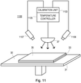
- Figure 11 shows an example of an apparatus 1100 in which a calibration test may be performed, for example according to the steps shown in Figures 3a to 3c (e.g. by applying an energy 37 over a build material 35 which has been deposited on a coalescing agent 33), and temperature then controlled accordingly.
- the apparatus comprises a temperature sensor 1107 and may comprise an optical sensor 1109, for example for respectively monitoring a temperature curve/data and/or visual monitoring as described above.
- a calibration test is performed by depositing a build material over a coalescing agent.
- a calibration test may involve depositing a build material, step 1201, and then depositing a coalescing agent over at least a portion of the build material, step 1203, and applying energy to the build material and coalescing agent, step 1205.
- the step of depositing a build material may comprise depositing a single layer of build material, or depositing multiple layers of build material.
- the steps described above for calibrating at least one temperature point may then be carried out, for example by electronically monitoring temperature curves or temperature data, or visually monitoring a surface, in order to calibrate the at least one temperature point (for example a melting point or a crystallization point).
- selective portions of a layer of build material can be coalesced or fused on a support which supports the build material (for example a support bed).
- a support which supports the build material (for example a support bed).
- Portions of the layer of build material on which an agent has been deposited for example selectively distributed with an agent distributor (for example a coalescing agent and a coalescence modifier agent) are coalesced, thus avoiding the rest of the build material on the support from reaching the fusing or melting point.
- an agent distributor for example a coalescing agent and a coalescence modifier agent
- a temperature point for example a crystallization point and/or a melting point of a build material
- a more precise control can lead to an improved melting process, and avoid poor quality objects from being generated, which might occur if the temperature points for a particular build material are not known precisely enough.
- an example comprises determining the melting point by depositing a coalescing agent, for example an absorbent ink that covers most of the build zone, recoating it with build material, for example with a powder, and applying a controlled temperature.
- a coalescing agent for example an absorbent ink that covers most of the build zone
- the melting point may be determined by applying energy, such as heat from a lamp, above the build zone such that the temperature rises until the build material (e.g. powder) reaches a point where the coalescing agent will rise through the build material (for example in an area where coalescing agent is applied). This process will occur at a constant temperature, as shown in Figure 4 above.
- energy such as heat from a lamp
- the crystallization point may be determined as follows. Once the melting point is surpassed, heating is no longer needed. Cooling, for example by removal of the energy source, or at a controlled pace, will crystallize the fused powder, also at a constant temperature, as shown in Figure 6 above.
- a calibrated temperature point for example the melting point and/or crystallization point, can be stored and used by a temperature controller.
- a calibrated temperature value(s) is used for the whole batch of build material.
- a calibrated temperature value(s) may be used for a current job/bucket, such that in this way variations due to environmental conditions, for example, are taken into account.
- a calibrated temperature value may be stored with other material calibrations in a "profile" which is generated ad-hoc or dynamically for a particular build material.
- the examples enable at least one precise working point of a build material, for example a powder or particulate material, to be determined and calibrated, independently of a particular manufacturer or batch.
- a build material for example a powder or particulate material
- the crystallization point and/or melting point are calibrated once for a particular batch of build material, and the apparatus controlled accordingly during subsequent processing of that particular batch of build material.
- the crystallization point and/or melting point are calibrated on a sample of build material from a batch of build material, and the apparatus controlled accordingly during subsequent processing of that particular batch of build material.
- the crystallization point and/or melting point are calibrated for a build material as the build material is being used to build a three-dimensional object.
- the calibration of a temperature is performed periodically to compensate for any environmental conditions that affect the build material.
- the process of generating a three-dimensional object can be made more robust, according to an example, by being able to correct the possible external contamination suffered by a build material (such as a powder) due to aging, temperature, or relative humidity.
- a build material such as a powder
- the examples described herein can enable a more stable, precise and controlled, printing process to be provided.
- An example enables desired properties (for example mechanical, accuracy or appearance) to be reproduced with any powder or particulate material.
- any variability in sensors or other components used to monitor temperature, or other system components which are used to generate a three-dimensional object may be compensated due to the calibration operation being carried out in the apparatus where a three dimensional object is to be generated, therefore taking any such variables into consideration during the calibration operations.
- a method of controlling the temperature of a build material used to generate a three-dimensional object comprising: preheating the build material to a temperature between a crystallization point of the build material and a melting point of the build material; wherein at least the crystallization point and/or the melting point is calibrated prior to preheating.
Description
- Additive manufacturing systems that generate three-dimensional objects on a layer-by-layer basis have been proposed as a potentially convenient way to produce three-dimensional objects.
- European Patent
EP1296788 discloses a method for generating 3D objects that comprises a temperature calibration algorithm. - The scope of the invention is defined by the appended independent claims. Further embodiments of the invention are defined by the dependent claims. Any embodiments which do not fall within the scope of the appended set of claims are to be interpreted as example embodiments of background information, useful only for understanding the invention.
- For a better understanding of the examples described herein, and to show more clearly how the examples may be carried into effect, reference will now be made, by way of example only, to the following drawings in which:
-
Figure 1 shows an example of a method for controlling temperature; -
Figure 2 shows an example of a method relating to a calibration test; -
Figures 3a to 3c are examples illustrating a method for performing a calibration test; -
Figure 4 shows an example of a temperature curve, and illustrates an example of a melting point; -
Figure 5 shows an example of a method for calibrating a melting point; -
Figure 6 shows an example of a temperature curve, and illustrates an example of a crystallization point; -
Figure 7 shows an example of a method for calibrating a crystallization point; -
Figures 8a to 8c show an example of a visualisation method; -
Figure 9 shows an example of a method for calibrating a crystallization point; -
Figure 10 shows an example of an apparatus for generating a three-dimensional object; -
Figure 11 shows an example of an apparatus for generating a three-dimensional object; and -
Figure 12 shows another example of a method relating to a calibration test. - A process of generating a tangible three-dimension object may comprise, for example, a series of steps which include forming a layer of build material, selectively delivering an agent (for example a coalescing agent and a coalescence modifier agent) to one or more portions of a surface of the layer of build material, and temporarily applying a predetermined level of energy to the layer of build material. The temporary application of energy may cause portions of the build material on which coalescing agent has been delivered or has penetrated to heat up above the melting point of the build material and to coalesce. Upon cooling, the portions which have coalesced become solid and form part of the three-dimensional object being generated. These steps are then repeated to form a three-dimensional object. Other steps and procedures may also be used with these steps for generating a three-dimensional object.
- In the examples described herein a coalescing agent and coalescence modifier agent can comprise fluids that may be delivered using any appropriate fluid delivery mechanism, also referred to as an agent distributor. In one example the agents are delivered in droplet form.
- A coalescence modifier agent may be used for a variety of purposes. In one example, a coalescence modifier agent may be delivered adjacent to where coalescing agent is delivered, for example to help reduce the effects of lateral coalescence bleed. This may be used, for example, to improve the definition or accuracy of object edges or surfaces, and/or to reduce surface roughness. In another example, coalescence modifier agent may be delivered interspersed with coalescing agent, which may be used to enable object properties to be modified.
- The examples described herein refer to a build material. In one example a build material is a powder-based build material. As used herein, the term powder-based material is intended to encompass both dry and wet powder-based materials, particulate materials, and granular materials.
- The examples described herein are related to a method and apparatus for controlling temperature in an apparatus for generating a three-dimensional object, wherein at least one temperature point in a build process is calibrated, the temperature point comprising a melting point and/or a crystallization point in a build process. As used in this document, "melting point" means the temperature at which build material becomes a coherent mass, for example by sintering, melting, fusing or coalescing. As will be described in greater detail in the examples below, a calibration test is performed to calibrate the at least one temperature point, the calibration test based on the build material that is to be used in generating a three-dimensional object. The calibration of at least one temperature point has the advantage of enabling a more accurate control of the temperature of the build material in relation to such calibrated temperature point(s), i.e. at a melting point and/or a crystallization point, when building a three-dimensional object or component. When generating a three-dimensional object, in one example the build material (e.g. powder or particulate material) is preheated between a crystallization temperature and a melting temperature. For example, the build material may be heated and kept just below a fusing temperature and kept above the crystallization point of the build material. Depending on the type of build material used (for example which type of powder-material, or which type of plastic, or the particular manufacturer used), the crystallization and melting points can change substantially. It is noted that there can also be variability in sensors that are used to monitor temperature, or other system components which are used to generate a three-dimensional object.
- According to the examples described herein, by calibrating at least one temperature point comprising at least one of the melting or crystallization points for a particular build material, this enables the characteristics of the build material to be controlled more accurately, allowing a three-dimensional object to be generated more reliably.
-
Figure 1 shows an example of an overview of a method of controlling temperature in an apparatus for generating a three-dimensional object which is described in greater detail below. The method comprises performing a calibration test on a sample of a build material that is to be used in generating a three-dimensional object,step 101. At least one temperature point is calibrated from the calibration test,step 103. Instep 105, the at least one calibrated temperature point is used during subsequent temperature control of the apparatus. -
Figure 2 shows an example of a method for performing the calibration test for calibrating at least one temperature point. The calibration test is used, to calibrate a crystallization point and/or a melting point that are to be used in a build process. The method comprises depositing coalescing agent on at least a portion of a build zone,step 201. It is noted that the coalescing agent may comprise any material or fluid that is used to interact or coalesce with build material when exposed to an energy source. For example the coalescing agent may comprise an absorbent ink or other printing fluid. It is noted that a coalescence modifier agent may also be deposited on or with the coalescing agent. Instep 203, build material is deposited over the coalescing agent. For example, a layer of build material may be deposited over at least a part of the coalescing agent where a monitoring operation is to be performed. In one example a single layer of build material is deposited on the coalescing agent. In another example multiple layers of build material are deposited on the coalescing agent. Instep 205 energy is applied to the build material. For example, the energy may be applied by an energy source for heating the build material, for example a lamp, a source of visible light, a source of ultra-violet light, a source of microwave energy, a source of radiation, or a laser source. Other sources of energy or heat may also be used. In one example a controlled amount of energy is applied. - In one
example step 201 comprises depositing coalescing agent over at least a portion of a build zone, for example in an area where temperature measurements are to be monitored or taken, for example in just a central area of the build zone, or in just one corner. According to another example,step 201 comprises depositing coalescing agent in a plurality of areas which are monitored to form an average or minimum or maximum value. In such an example a calibration test may be performed in each one of a plurality of regions that can be separately monitored. In another example,step 201 comprises depositing coalescing agent over an entire build zone. In each of these examples at least one thermal sensor, for example a thermal camera or a sensor array, may be used to monitor a particular region or multiple regions, or the entire build zone. -
Figures 3a to 3c show an example illustrating further how the method ofFigure 2 may be carried out. InFigure 3a coalescing agent 33 is shown as being deposited, for example in at least a portion of a build zone 32 (the build zone being defined, for example, by asupport 31, for example the surface of a bed, such as a powder bed). InFigure 3b build material 35, for example a layer of powder, is formed or deposited over the coalescingagent 33. In one example the layer of build material is deposited over an entire print area (and thus over the coalescing agent). In another example the layer of build material is deposited over at least a portion of the coalescing agent. As mentioned above, a single layer or multiple layers of build material may be deposited. It is noted that the thicknesses of the layers shown in the Figures are for illustrative purposes only, and may differ or vary from what is shown.Figure 3c showsenergy 37 being applied over the build material, for example a controlled energy from a lamp or heat source which heats thebuild material 35. As mentioned above, the coalescing agent and build material may be deposited over other regions or areas, other than the example shown inFigures 3a to 3c . -
Figure 4 shows an example of a temperature curve which is useful for understanding the invention, and illustrates an example of a melting point of a build material. As energy is applied over the build material, the temperature rises until aregion 40 is reached, corresponding to a temperature point at which a melting point is reached. In one example this process will occur at a constant temperature for a particular build material (i.e. regardless of which coalescing material is used, for example when the build material has the greater effect on the melting point). In such an example a calibration test may be performed for each build material being used. In another example, this process will occur at a constant temperature for a particular combination of build material and coalescing agent. In such an example a calibration test may be performed for each combination of build material and coalescing agent being used. - Therefore, by performing the calibration steps of Figurers 2 or 3a to 3c, and then determining at which temperature the melting point is reached, this enables an example to calibrate the melting point for a particular build material, or combination of build material and coalescing agent.
- In one example a temperature curve or temperature data may be monitored while a calibration test such as that shown in
Figures 2 and3a to 3c is performed. -
Figure 5 shows an example of a method for calibrating the melting point. In step 501 a temperature signal relating to the temperature of the build material is received as the energy is applied to the build material. The temperature signal may be received, for example, from a temperature sensor that monitors the temperature of the build material. It is noted that a temperature sensor may comprise, for example, a non-contact temperature sensor or a thermal sensor, such as an Infra Red sensor. In one example the temperature sensor is a temperature sensor that is also used in part of a normal build process. More than one sensor may also be used where multiple regions are being monitored. The received temperature signal is monitored to detect a temperature change that is characteristic of a melting point,step 503. Detecting the temperature change may comprise, for example, detecting the characteristic 40 shown in the temperature curve ofFigure 4 . The calibrated melting point is then set as the temperature at which the temperature change is detected,step 505. - In one example, monitoring a temperature signal comprises monitoring a profile of a temperature curve or monitoring temperature data. This may involve comparing a received temperature curve with a predetermined temperature curve or profile, or by matching a temperature curve with a set of temperature curves. In one example, monitoring a temperature signal comprises comparing received temperature data with predetermined data which represents a melting point, for example to detect a particular pattern in the received temperature data.
-
Figure 6 shows an example of a temperature curve which is useful for understanding the invention, and illustrates an example of acrystallization point 60. The temperature curve may be generated, for example, by the method shown inFigures 2 or3a to 3c . After the energy source is removed and the build material allowed to cool, the temperature falls until aregion 60 is reached, corresponding to a temperature at which a crystallization point is reached. In one example this process will occur at a constant temperature for a particular build material (i.e. regardless of which coalescing material is used, for example when the build material has the greater effect on the crystallization point). In such an example a calibration test may be performed for each build material being used. In another example, this process will occur at a constant temperature for a particular combination of build material and coalescing agent. In such an example a calibration test may be performed for each combination of build material and coalescing agent being used. -
Figure 7 shows an example of a method for calibrating a crystallization point. Instep 701 the method comprises applying energy to the build material (the build material being over a coalescing agent, for example as described in the examples ofFigures 2 and3a to 3c ), until the build material has exceeded a melting point. In step 703 a temperature signal is received relating to the temperature of the build material as the build material cools. The received temperature signal is monitored to detect a temperature change that is characteristic of a crystallization point,step 705. The calibrated crystallization point is set as the temperature at which the temperature change is detected,step 707. - In one example the rate at which the build material cools to the crystallization point is controlled, for example by controlled removal of the energy source.
- As with the example of the melting point described above, the monitoring of a temperature signal may comprise monitoring a profile of a temperature curve or monitoring temperature data. This may involve comparing a received temperature curve with a predetermined temperature curve or profile, or comparing received temperature data with predetermined data which represents a crystallization point, for example to detect a particular pattern in the received temperature data, or by matching a temperature curve with a set of temperature curves.
- Thus, in an example described herein, detecting a characteristic temperature change may comprise comparing the profile of the temperature curve with at least one predetermined curve representing the characteristic of a crystallization point or melting point, or comparing temperature data with predetermined temperature data representing the characteristic of a crystallization point or melting point.
- An example may therefore involve the analysis of temperature logs to determine a melting point using a thermal sensor. Since the phase change of the build material/coalescing agent occurs at a consistent temperature, it can be monitored and well-defined as shown for example in
Figure 4 above. The crystallization point can be determined by the same methodology, based on the characteristics shown for example inFigure 6 above. - While the examples described above relate to monitoring a temperature signal, such as a temperature curve or temperature data, according to one example the calibration of a melting point may be performed visually.
-
Figures 8a to 8c show an example of how a temperature point may be calibrated using a visual indicator. -
Figure 8a shows a layer ofbuild material 81 which has been deposited over a coalescing agent. In response to being exposed to an energy source, for example heated by a lamp or heat source, the build material begins to undergo a phase change as the temperature rises, the phase change illustrated bysection 83 inFigure 8b . As the temperature continues to rise, a melting point can be visually determined when the coalescing agent and build material have melted and fused, as illustrated by thesection 85 inFigure 8c . -
Figure 9 shows a method according to an example for calibrating a melting point. The method comprises, instep 901, visually monitoring the build material as energy is applied over the build material. In step 903 a predetermined color change in the build material is detected, that is characteristic of a melting point. Instep 905 the calibrated melting point is set as the temperature at which the predetermined color change is detected. - In one example detecting a predetermined color change comprises determining whether a color density has reached a specified level.
- In one example the visual monitoring is performed by an optical sensing device. In an example where a sensor comprises a light sensor or densitometer, the step of monitoring may comprise taking a value, and determining whether this read value has reached a threshold value, such as a previously established threshold value (for example performed during a previous calibration test for a particular build material and/or coalescing agent being used). In another example the visual monitoring is performed by an operator of the apparatus.
- Thus, in one example a melting point can be determined by visual observation, for example observing the color modification of the top layer or surface of the build material. When the color density reaches a specified level, for example corresponding to
Figure 8c , it indicates the fusion of the build material, for example complete fusion of the powder. Using an optical sensing device it is possible to define the melting point, and calibrate the melting point as the temperature of the build material at that point. - In an example, applying a controlled energy may comprise applying heat above the build zone until the coalescing agent penetrates through at least part of the build material.
-
Figure 10 shows an example of anapparatus 1000 for generating a three-dimensional object. The apparatus comprises anenergy source 1001 to heat a build material. Acalibrating unit 1003 calibrates at least one temperature point using a sample of build material that is to be used to generate a three-dimensional object. Atemperature controller 1005 controls the energy source 1101 using the at least one calibrated temperature point. For example, thetemperature controller 1005 can adapt or adjust the power supplied to an energy source, or the energy emitted thereby, according to the calibrated temperature, such that a more accurate build process can be carried out. - The
apparatus 1000 comprises atemperature sensor 1007 coupled to thecalibration unit 1003, to provide the calibration unit with temperature signals relating to the build material (for example for monitoring a temperature curve or temperature data as mentioned above). In one example theapparatus 1000 comprises anoptical sensor 1009 coupled to the calibration unit, to monitor a surface of the build material during a calibration test (for example to optically detect a particular temperature point as described above). -
Figure 11 shows an example of anapparatus 1100 in which a calibration test may be performed, for example according to the steps shown inFigures 3a to 3c (e.g. by applying anenergy 37 over abuild material 35 which has been deposited on a coalescing agent 33), and temperature then controlled accordingly. The apparatus comprises atemperature sensor 1107 and may comprise anoptical sensor 1109, for example for respectively monitoring a temperature curve/data and/or visual monitoring as described above. - In the examples described above a calibration test is performed by depositing a build material over a coalescing agent. According to another example shown in
Figure 12 , however, a calibration test may involve depositing a build material,step 1201, and then depositing a coalescing agent over at least a portion of the build material,step 1203, and applying energy to the build material and coalescing agent,step 1205. The step of depositing a build material may comprise depositing a single layer of build material, or depositing multiple layers of build material. In one example the steps described above for calibrating at least one temperature point may then be carried out, for example by electronically monitoring temperature curves or temperature data, or visually monitoring a surface, in order to calibrate the at least one temperature point (for example a melting point or a crystallization point). - In an example of an apparatus for generating a three-dimensional object, selective portions of a layer of build material can be coalesced or fused on a support which supports the build material (for example a support bed). Portions of the layer of build material on which an agent has been deposited, for example selectively distributed with an agent distributor (for example a coalescing agent and a coalescence modifier agent) are coalesced, thus avoiding the rest of the build material on the support from reaching the fusing or melting point. By calibrating at least one of these temperature points, any variability of the temperature where each different build material crystallizes and fuses can be compensated for. The calibration can also compensate for a variability in a system parameter, such as sensor sensitivity.
- By calibrating a temperature point, for example a crystallization point and/or a melting point of a build material, this enables an example to provide a more precise control of the build process.
- A more precise control can lead to an improved melting process, and avoid poor quality objects from being generated, which might occur if the temperature points for a particular build material are not known precisely enough.
- From the above it can be seen that an example comprises determining the melting point by depositing a coalescing agent, for example an absorbent ink that covers most of the build zone, recoating it with build material, for example with a powder, and applying a controlled temperature.
- In an example the melting point may be determined by applying energy, such as heat from a lamp, above the build zone such that the temperature rises until the build material (e.g. powder) reaches a point where the coalescing agent will rise through the build material (for example in an area where coalescing agent is applied). This process will occur at a constant temperature, as shown in
Figure 4 above. - In an example the crystallization point may be determined as follows. Once the melting point is surpassed, heating is no longer needed. Cooling, for example by removal of the energy source, or at a controlled pace, will crystallize the fused powder, also at a constant temperature, as shown in
Figure 6 above. - A calibrated temperature point, for example the melting point and/or crystallization point, can be stored and used by a temperature controller. In one example a calibrated temperature value(s) is used for the whole batch of build material. In another example a calibrated temperature value(s) may be used for a current job/bucket, such that in this way variations due to environmental conditions, for example, are taken into account. In one example, a calibrated temperature value may be stored with other material calibrations in a "profile" which is generated ad-hoc or dynamically for a particular build material.
- The examples enable at least one precise working point of a build material, for example a powder or particulate material, to be determined and calibrated, independently of a particular manufacturer or batch.
- Thus, in one example the crystallization point and/or melting point are calibrated once for a particular batch of build material, and the apparatus controlled accordingly during subsequent processing of that particular batch of build material.
- In one example, the crystallization point and/or melting point are calibrated on a sample of build material from a batch of build material, and the apparatus controlled accordingly during subsequent processing of that particular batch of build material.
- In one example, the crystallization point and/or melting point are calibrated for a build material as the build material is being used to build a three-dimensional object.
- In one example the calibration of a temperature, for example the crystallization point and/or the melting point, is performed periodically to compensate for any environmental conditions that affect the build material.
- The process of generating a three-dimensional object can be made more robust, according to an example, by being able to correct the possible external contamination suffered by a build material (such as a powder) due to aging, temperature, or relative humidity.
- The examples described herein can enable a more stable, precise and controlled, printing process to be provided. An example enables desired properties (for example mechanical, accuracy or appearance) to be reproduced with any powder or particulate material.
- In one example, any variability in sensors or other components used to monitor temperature, or other system components which are used to generate a three-dimensional object, may be compensated due to the calibration operation being carried out in the apparatus where a three dimensional object is to be generated, therefore taking any such variables into consideration during the calibration operations.
- According to an example there is provided a method of controlling the temperature of a build material used to generate a three-dimensional object, the method comprising: preheating the build material to a temperature between a crystallization point of the build material and a melting point of the build material; wherein at least the crystallization point and/or the melting point is calibrated prior to preheating.
- Although some of the examples described above refer to delivering a coalescing agent and a coalescence modifier agent, it is noted that the examples may be used with an apparatus that delivers just one form of agent, or multiple different agents.
- In the examples above, by delivering the build material over an agent, rather than vice versa, this has an advantage of enabling a melting point to be detected more easily.
- It should be noted that the above-mentioned examples illustrate rather than limit what is described herein, and that those skilled in the art will be able to design many alternative examples without departing from the scope of the appended claims. The word "comprising" does not exclude the presence of elements or steps other than those listed in a claim, "a" or "an" does not exclude a plurality, and a single processor or other unit may fulfil the functions of several units recited in the claims. Any reference signs in the claims shall not be construed so as to limit their scope.
Claims (13)
- A method of controlling temperature in an apparatus for generating a three-dimensional object, the method comprising:performing a calibration test on a sample of build material that is to be used in generating a three-dimensional object, wherein performing the calibration test comprises:depositing a build material and a coalescing agent in a build zone and applying energy thereto;receiving a temperature signal relating to the temperature of the build material; andmonitoring the received temperature signal to detect a temperature change that is characteristic of a temperature point;wherein the method further comprises:calibrating at least one temperature point from the calibration test; andusing the at least one calibrated temperature point during subsequent temperature control of the apparatus, whereinthe at least one calibrated temperature point is calibrated on a sample of build material from a batch of build material, and the method comprises controlling an energy source of the apparatus using the at least one calibrated temperature point during subsequent processing of that particular batch of build material; and whereini. the temperature point is a melting point and the method comprises monitoring the received temperature signal as the energy is applied to the build material, detecting a temperature change that is characteristic of a melting point and setting the calibrated melting point as the temperature at which the temperature change is detected; and/orii. the temperature point is a crystallization point, and the method comprises applying energy to the build material until the build material has exceeded a melting point, receiving a temperature signal relating to the temperature of the build material as the build material cools, monitoring the received temperature signal to detect a temperature change that is characteristic of a crystallization point, and setting the calibrated crystallization point as the temperature at which the temperature change is detected.
- A method as claimed in claim 1, wherein the calibration test comprises:depositing a coalescing agent;depositing build material on the coalescing agent; andapplying energy to the build material.
- A method as claimed in claim 1, wherein the calibration test comprises:depositing a build material;depositing a coalescing agent over at least a portion of a build material; andapplying energy to the build material and coalescing agent.
- A method as claimed in any preceding claim, wherein monitoring a temperature signal comprises monitoring a profile of a temperature curve or monitoring temperature data.
- A method as claimed in claim 4, wherein detecting a temperature change that is characteristic of a melting point or crystallization point comprises:comparing the profile of the temperature curve with at least one predetermined curve representing the characteristic of a crystallization point or melting point.
- A method as claimed in claim 4, wherein detecting a temperature change that is characteristic of a melting point or crystallization point comprises comparing temperature data with predetermined temperature data representing the characteristic of a crystallization point or melting point.
- A method as claimed in any preceding claim, wherein applying the energy comprises applying heat above the build zone until the build material and coalescing agent coalesce.
- A method as claimed in any preceding claim, wherein applying the energy comprises applying heat above the build zone until a coalescing agent is absorbed through at least part of the build material.
- A method as claimed in any one of the preceding claims wherein:a crystallization point and/or melting point are calibrated once for a particular batch of build material, and the apparatus controlled accordingly during subsequent processing of that particular batch of build material.
- A method as claimed in any one of the preceding claims wherein a crystallization point and/or melting point are calibrated for a build material as the build material is being used to build a three-dimensional object.
- A method as claimed in any one of the preceding claims, wherein the calibration of a temperature point, a crystallization point or a melting point is performed periodically.
- Apparatus (1000) for generating a three-dimensional object, the apparatus comprising:an energy source (1101) configured to heat a build material;a calibrating unit (1103) configured to determine a calibrated temperature point;a temperature sensor (1107) coupled to the calibration unit, configured to provide the calibration unit with temperature signals relating to a build material; anda temperature controller (1105) configured to control the energy source using the at least one calibrated temperature point during subsequent temperature control of the apparatus, wherein the at least one calibrated temperature point is calibrated on a sample of build material from a batch of build material, and the temperature controller (1105) is configured to use the at least one calibrated temperature point during subsequent processing of that particular batch of build material; and whereini. the temperature point is a melting point and the temperature sensor (1107) is configured to monitor a temperature signal received as energy is applied to a sample of build material and a coalescing agent deposited in a build zone, and the apparatus (1000) is configured to detect a temperature change that is characteristic of a melting point and to set the calibrated melting point as the temperature at which the temperature change is detected; and/orii. the temperature point is a crystallization point, and the temperature sensor (1107) is configured to monitor a temperature signal relating to the temperature of a sample of build material as the build material cools and the apparatus (1000) is configured to apply energy to a build material and a coalescing agent deposited in a build zone until the build material has exceeded a melting point, receive a temperature signal relating to the temperature of a sample of build material as the build material cools, monitor the received temperature signal to detect a temperature change that is characteristic of a crystallization point and set the calibrated crystallization point as the temperature at which the temperature change is detected.
- An apparatus (1100) as claimed in claim 12 comprising:an optical sensor (1109) coupled to the calibration unit, configured to monitor a surface of the build material during a calibration test.
Applications Claiming Priority (1)
| Application Number | Priority Date | Filing Date | Title |
|---|---|---|---|
| PCT/EP2014/071243 WO2016050322A1 (en) | 2014-10-03 | 2014-10-03 | Controlling temperature in an apparatus for generating a three-dimensional object |
Publications (2)
| Publication Number | Publication Date |
|---|---|
| EP3200973A1 EP3200973A1 (en) | 2017-08-09 |
| EP3200973B1 true EP3200973B1 (en) | 2022-02-09 |
Family
ID=51662098
Family Applications (1)
| Application Number | Title | Priority Date | Filing Date |
|---|---|---|---|
| EP14781164.0A Active EP3200973B1 (en) | 2014-10-03 | 2014-10-03 | Controlling temperature in an apparatus for generating a three-dimensional object |
Country Status (4)
| Country | Link |
|---|---|
| US (1) | US10730242B2 (en) |
| EP (1) | EP3200973B1 (en) |
| CN (1) | CN106794630B (en) |
| WO (1) | WO2016050322A1 (en) |
Families Citing this family (12)
| Publication number | Priority date | Publication date | Assignee | Title |
|---|---|---|---|---|
| US9999924B2 (en) | 2014-08-22 | 2018-06-19 | Sigma Labs, Inc. | Method and system for monitoring additive manufacturing processes |
| EP3221076A4 (en) * | 2014-11-18 | 2018-07-18 | Sigma Labs, Inc. | Multi-sensor quality inference and control for additive manufacturing processes |
| US10786948B2 (en) | 2014-11-18 | 2020-09-29 | Sigma Labs, Inc. | Multi-sensor quality inference and control for additive manufacturing processes |
| WO2016115284A1 (en) | 2015-01-13 | 2016-07-21 | Sigma Labs, Inc. | Material qualification system and methodology |
| US10569470B2 (en) * | 2015-01-30 | 2020-02-25 | Hewlett-Packard Development Company, L.P. | Agent calibration |
| US10207489B2 (en) | 2015-09-30 | 2019-02-19 | Sigma Labs, Inc. | Systems and methods for additive manufacturing operations |
| WO2017196338A1 (en) * | 2016-05-12 | 2017-11-16 | Hewlett-Packard Development Company, L.P. | Printer warming device control |
| WO2017196345A1 (en) * | 2016-05-12 | 2017-11-16 | Hewlett-Packard Development Company, L.P. | Heating lamp calibration |
| EP3390012B1 (en) * | 2016-05-12 | 2020-09-30 | Hewlett-Packard Development Company, L.P. | Fuse lamp calibration |
| GB2594705B (en) * | 2020-04-24 | 2023-02-08 | Stratasys Powder Production Ltd | Improved apparatus and methods for the layer-by-layer formation of three dimensional objects |
| GB2610620A (en) * | 2021-09-13 | 2023-03-15 | Stratasys Powder Production Ltd | Method for determining a set point for a thermal sensor in an apparatus for the manufacture of 3D objects |
| GB2610618A (en) * | 2021-09-13 | 2023-03-15 | Stratasys Powder Production Ltd | The method for determining a set point for a thermal sensor in an apparatus for the manufacture of 3D objects |
Family Cites Families (13)
| Publication number | Priority date | Publication date | Assignee | Title |
|---|---|---|---|---|
| WO2001038061A1 (en) * | 1999-10-26 | 2001-05-31 | University Of Southern California | Process of making a three-dimensional object |
| SE521124C2 (en) * | 2000-04-27 | 2003-09-30 | Arcam Ab | Device and method for making a three-dimensional product |
| US20020020945A1 (en) | 2000-08-18 | 2002-02-21 | Uichung Cho | Forming three dimensional objects through bulk heating of layers with differential material properties |
| GB0317387D0 (en) | 2003-07-25 | 2003-08-27 | Univ Loughborough | Method and apparatus for combining particulate material |
| US7261542B2 (en) | 2004-03-18 | 2007-08-28 | Desktop Factory, Inc. | Apparatus for three dimensional printing using image layers |
| DE102004020452A1 (en) | 2004-04-27 | 2005-12-01 | Degussa Ag | Method for producing three-dimensional objects by means of electromagnetic radiation and applying an absorber by inkjet method |
| US6930278B1 (en) * | 2004-08-13 | 2005-08-16 | 3D Systems, Inc. | Continuous calibration of a non-contact thermal sensor for laser sintering |
| EP2001656B1 (en) | 2006-04-06 | 2014-10-15 | 3D Systems Incorporated | KiT FOR THE PRODUCTION OF THREE-DIMENSIONAL OBJECTS BY USE OF ELECTROMAGNETIC RADIATION |
| US20080122141A1 (en) | 2006-11-29 | 2008-05-29 | Bryan Bedal | Sinterable Powder |
| DE102007024469B4 (en) | 2007-05-25 | 2009-04-23 | Eos Gmbh Electro Optical Systems | Method of layering a three-dimensional object |
| EP2402097A4 (en) | 2009-02-24 | 2014-04-09 | Panasonic Corp | Process for producing three-dimensional shape and three-dimensional shape obtained thereby |
| US8257895B2 (en) | 2009-10-09 | 2012-09-04 | Xerox Corporation | Toner compositions and processes |
| FR2994885B1 (en) * | 2012-08-29 | 2014-08-29 | Carpyz | MACHINES FOR THE PRODUCTION OF CIRCULAR PRODUCTS BY LAYERED ADDITION |
-
2014
- 2014-10-03 CN CN201480082483.2A patent/CN106794630B/en active Active
- 2014-10-03 US US15/513,457 patent/US10730242B2/en active Active
- 2014-10-03 EP EP14781164.0A patent/EP3200973B1/en active Active
- 2014-10-03 WO PCT/EP2014/071243 patent/WO2016050322A1/en active Application Filing
Also Published As
| Publication number | Publication date |
|---|---|
| US20170297265A1 (en) | 2017-10-19 |
| WO2016050322A1 (en) | 2016-04-07 |
| CN106794630A (en) | 2017-05-31 |
| EP3200973A1 (en) | 2017-08-09 |
| CN106794630B (en) | 2020-10-30 |
| US10730242B2 (en) | 2020-08-04 |
Similar Documents
| Publication | Publication Date | Title |
|---|---|---|
| EP3200973B1 (en) | Controlling temperature in an apparatus for generating a three-dimensional object | |
| KR101976970B1 (en) | Temperature determination technique of additive manufacturing system | |
| EP3065935B1 (en) | Fabricating three dimensional objects | |
| US11179894B2 (en) | Managing thermal contributions between layers during additive manufacturing | |
| JP5555769B2 (en) | Method and apparatus for making a three-dimensional object | |
| US20170217104A1 (en) | Controlling heating of a surface | |
| JP6928715B2 (en) | Additional manufacturing temperature | |
| KR20180124998A (en) | Temperature compensation technique by applying printing agent | |
| US20180001568A1 (en) | Calibration of apparatus | |
| US20180264737A1 (en) | Determining layer thickness | |
| EP3271160B1 (en) | Build material analysis | |
| US20190061267A1 (en) | Thermal imaging device calibration | |
| US20220048113A1 (en) | Heat source calibration | |
| WO2019022700A1 (en) | Calibrating heat sensors | |
| US20230126641A1 (en) | Build layer coverage analysis | |
| US20210370596A1 (en) | Controlling an energy source of an additive manufacturing system | |
| US20220402224A1 (en) | Build temperature control | |
| WO2023027682A1 (en) | Regional additive manufacturing thermal sensors |
Legal Events
| Date | Code | Title | Description |
|---|---|---|---|
| STAA | Information on the status of an ep patent application or granted ep patent |
Free format text: STATUS: THE INTERNATIONAL PUBLICATION HAS BEEN MADE |
|
| PUAI | Public reference made under article 153(3) epc to a published international application that has entered the european phase |
Free format text: ORIGINAL CODE: 0009012 |
|
| STAA | Information on the status of an ep patent application or granted ep patent |
Free format text: STATUS: REQUEST FOR EXAMINATION WAS MADE |
|
| 17P | Request for examination filed |
Effective date: 20170331 |
|
| AK | Designated contracting states |
Kind code of ref document: A1 Designated state(s): AL AT BE BG CH CY CZ DE DK EE ES FI FR GB GR HR HU IE IS IT LI LT LU LV MC MK MT NL NO PL PT RO RS SE SI SK SM TR |
|
| AX | Request for extension of the european patent |
Extension state: BA ME |
|
| RIN1 | Information on inventor provided before grant (corrected) |
Inventor name: RAMIREZ MUELA, DAVID Inventor name: PUIGARDEU ARAMENDIA, SERGIO Inventor name: FORNOS, POL Inventor name: SANCHEZ RIBES, SALVADOR |
|
| DAX | Request for extension of the european patent (deleted) | ||
| RAP1 | Party data changed (applicant data changed or rights of an application transferred) |
Owner name: HEWLETT-PACKARD DEVELOPMENT COMPANY, L.P. |
|
| STAA | Information on the status of an ep patent application or granted ep patent |
Free format text: STATUS: EXAMINATION IS IN PROGRESS |
|
| 17Q | First examination report despatched |
Effective date: 20190814 |
|
| STAA | Information on the status of an ep patent application or granted ep patent |
Free format text: STATUS: EXAMINATION IS IN PROGRESS |
|
| REG | Reference to a national code |
Ref country code: DE Ref legal event code: R079 Ref document number: 602014082442 Country of ref document: DE Free format text: PREVIOUS MAIN CLASS: B29C0067000000 Ipc: B29C0035020000 |
|
| RIC1 | Information provided on ipc code assigned before grant |
Ipc: B29C 64/10 20170101ALI20210727BHEP Ipc: B29C 64/393 20170101ALI20210727BHEP Ipc: B29C 64/165 20170101ALI20210727BHEP Ipc: B33Y 50/02 20150101ALI20210727BHEP Ipc: B33Y 30/00 20150101ALI20210727BHEP Ipc: B29C 35/02 20060101AFI20210727BHEP |
|
| GRAP | Despatch of communication of intention to grant a patent |
Free format text: ORIGINAL CODE: EPIDOSNIGR1 |
|
| STAA | Information on the status of an ep patent application or granted ep patent |
Free format text: STATUS: GRANT OF PATENT IS INTENDED |
|
| INTG | Intention to grant announced |
Effective date: 20210923 |
|
| GRAS | Grant fee paid |
Free format text: ORIGINAL CODE: EPIDOSNIGR3 |
|
| GRAA | (expected) grant |
Free format text: ORIGINAL CODE: 0009210 |
|
| STAA | Information on the status of an ep patent application or granted ep patent |
Free format text: STATUS: THE PATENT HAS BEEN GRANTED |
|
| AK | Designated contracting states |
Kind code of ref document: B1 Designated state(s): AL AT BE BG CH CY CZ DE DK EE ES FI FR GB GR HR HU IE IS IT LI LT LU LV MC MK MT NL NO PL PT RO RS SE SI SK SM TR |
|
| REG | Reference to a national code |
Ref country code: GB Ref legal event code: FG4D |
|
| REG | Reference to a national code |
Ref country code: CH Ref legal event code: EP Ref country code: AT Ref legal event code: REF Ref document number: 1467236 Country of ref document: AT Kind code of ref document: T Effective date: 20220215 |
|
| REG | Reference to a national code |
Ref country code: IE Ref legal event code: FG4D |
|
| REG | Reference to a national code |
Ref country code: DE Ref legal event code: R096 Ref document number: 602014082442 Country of ref document: DE |
|
| REG | Reference to a national code |
Ref country code: LT Ref legal event code: MG9D |
|
| REG | Reference to a national code |
Ref country code: NL Ref legal event code: MP Effective date: 20220209 |
|
| REG | Reference to a national code |
Ref country code: AT Ref legal event code: MK05 Ref document number: 1467236 Country of ref document: AT Kind code of ref document: T Effective date: 20220209 |
|
| PG25 | Lapsed in a contracting state [announced via postgrant information from national office to epo] |
Ref country code: SE Free format text: LAPSE BECAUSE OF FAILURE TO SUBMIT A TRANSLATION OF THE DESCRIPTION OR TO PAY THE FEE WITHIN THE PRESCRIBED TIME-LIMIT Effective date: 20220209 Ref country code: RS Free format text: LAPSE BECAUSE OF FAILURE TO SUBMIT A TRANSLATION OF THE DESCRIPTION OR TO PAY THE FEE WITHIN THE PRESCRIBED TIME-LIMIT Effective date: 20220209 Ref country code: PT Free format text: LAPSE BECAUSE OF FAILURE TO SUBMIT A TRANSLATION OF THE DESCRIPTION OR TO PAY THE FEE WITHIN THE PRESCRIBED TIME-LIMIT Effective date: 20220609 Ref country code: NO Free format text: LAPSE BECAUSE OF FAILURE TO SUBMIT A TRANSLATION OF THE DESCRIPTION OR TO PAY THE FEE WITHIN THE PRESCRIBED TIME-LIMIT Effective date: 20220509 Ref country code: NL Free format text: LAPSE BECAUSE OF FAILURE TO SUBMIT A TRANSLATION OF THE DESCRIPTION OR TO PAY THE FEE WITHIN THE PRESCRIBED TIME-LIMIT Effective date: 20220209 Ref country code: LT Free format text: LAPSE BECAUSE OF FAILURE TO SUBMIT A TRANSLATION OF THE DESCRIPTION OR TO PAY THE FEE WITHIN THE PRESCRIBED TIME-LIMIT Effective date: 20220209 Ref country code: HR Free format text: LAPSE BECAUSE OF FAILURE TO SUBMIT A TRANSLATION OF THE DESCRIPTION OR TO PAY THE FEE WITHIN THE PRESCRIBED TIME-LIMIT Effective date: 20220209 Ref country code: ES Free format text: LAPSE BECAUSE OF FAILURE TO SUBMIT A TRANSLATION OF THE DESCRIPTION OR TO PAY THE FEE WITHIN THE PRESCRIBED TIME-LIMIT Effective date: 20220209 Ref country code: BG Free format text: LAPSE BECAUSE OF FAILURE TO SUBMIT A TRANSLATION OF THE DESCRIPTION OR TO PAY THE FEE WITHIN THE PRESCRIBED TIME-LIMIT Effective date: 20220509 |
|
| PG25 | Lapsed in a contracting state [announced via postgrant information from national office to epo] |
Ref country code: PL Free format text: LAPSE BECAUSE OF FAILURE TO SUBMIT A TRANSLATION OF THE DESCRIPTION OR TO PAY THE FEE WITHIN THE PRESCRIBED TIME-LIMIT Effective date: 20220209 Ref country code: LV Free format text: LAPSE BECAUSE OF FAILURE TO SUBMIT A TRANSLATION OF THE DESCRIPTION OR TO PAY THE FEE WITHIN THE PRESCRIBED TIME-LIMIT Effective date: 20220209 Ref country code: GR Free format text: LAPSE BECAUSE OF FAILURE TO SUBMIT A TRANSLATION OF THE DESCRIPTION OR TO PAY THE FEE WITHIN THE PRESCRIBED TIME-LIMIT Effective date: 20220510 Ref country code: FI Free format text: LAPSE BECAUSE OF FAILURE TO SUBMIT A TRANSLATION OF THE DESCRIPTION OR TO PAY THE FEE WITHIN THE PRESCRIBED TIME-LIMIT Effective date: 20220209 Ref country code: AT Free format text: LAPSE BECAUSE OF FAILURE TO SUBMIT A TRANSLATION OF THE DESCRIPTION OR TO PAY THE FEE WITHIN THE PRESCRIBED TIME-LIMIT Effective date: 20220209 |
|
| PG25 | Lapsed in a contracting state [announced via postgrant information from national office to epo] |
Ref country code: IS Free format text: LAPSE BECAUSE OF FAILURE TO SUBMIT A TRANSLATION OF THE DESCRIPTION OR TO PAY THE FEE WITHIN THE PRESCRIBED TIME-LIMIT Effective date: 20220609 |
|
| PG25 | Lapsed in a contracting state [announced via postgrant information from national office to epo] |
Ref country code: SM Free format text: LAPSE BECAUSE OF FAILURE TO SUBMIT A TRANSLATION OF THE DESCRIPTION OR TO PAY THE FEE WITHIN THE PRESCRIBED TIME-LIMIT Effective date: 20220209 Ref country code: SK Free format text: LAPSE BECAUSE OF FAILURE TO SUBMIT A TRANSLATION OF THE DESCRIPTION OR TO PAY THE FEE WITHIN THE PRESCRIBED TIME-LIMIT Effective date: 20220209 Ref country code: RO Free format text: LAPSE BECAUSE OF FAILURE TO SUBMIT A TRANSLATION OF THE DESCRIPTION OR TO PAY THE FEE WITHIN THE PRESCRIBED TIME-LIMIT Effective date: 20220209 Ref country code: EE Free format text: LAPSE BECAUSE OF FAILURE TO SUBMIT A TRANSLATION OF THE DESCRIPTION OR TO PAY THE FEE WITHIN THE PRESCRIBED TIME-LIMIT Effective date: 20220209 Ref country code: DK Free format text: LAPSE BECAUSE OF FAILURE TO SUBMIT A TRANSLATION OF THE DESCRIPTION OR TO PAY THE FEE WITHIN THE PRESCRIBED TIME-LIMIT Effective date: 20220209 Ref country code: CZ Free format text: LAPSE BECAUSE OF FAILURE TO SUBMIT A TRANSLATION OF THE DESCRIPTION OR TO PAY THE FEE WITHIN THE PRESCRIBED TIME-LIMIT Effective date: 20220209 |
|
| REG | Reference to a national code |
Ref country code: DE Ref legal event code: R097 Ref document number: 602014082442 Country of ref document: DE |
|
| PG25 | Lapsed in a contracting state [announced via postgrant information from national office to epo] |
Ref country code: AL Free format text: LAPSE BECAUSE OF FAILURE TO SUBMIT A TRANSLATION OF THE DESCRIPTION OR TO PAY THE FEE WITHIN THE PRESCRIBED TIME-LIMIT Effective date: 20220209 |
|
| PLBE | No opposition filed within time limit |
Free format text: ORIGINAL CODE: 0009261 |
|
| STAA | Information on the status of an ep patent application or granted ep patent |
Free format text: STATUS: NO OPPOSITION FILED WITHIN TIME LIMIT |
|
| 26N | No opposition filed |
Effective date: 20221110 |
|
| PG25 | Lapsed in a contracting state [announced via postgrant information from national office to epo] |
Ref country code: SI Free format text: LAPSE BECAUSE OF FAILURE TO SUBMIT A TRANSLATION OF THE DESCRIPTION OR TO PAY THE FEE WITHIN THE PRESCRIBED TIME-LIMIT Effective date: 20220209 |
|
| PG25 | Lapsed in a contracting state [announced via postgrant information from national office to epo] |
Ref country code: MC Free format text: LAPSE BECAUSE OF FAILURE TO SUBMIT A TRANSLATION OF THE DESCRIPTION OR TO PAY THE FEE WITHIN THE PRESCRIBED TIME-LIMIT Effective date: 20220209 |
|
| REG | Reference to a national code |
Ref country code: CH Ref legal event code: PL |
|
| REG | Reference to a national code |
Ref country code: BE Ref legal event code: MM Effective date: 20221031 |
|
| PG25 | Lapsed in a contracting state [announced via postgrant information from national office to epo] |
Ref country code: LU Free format text: LAPSE BECAUSE OF NON-PAYMENT OF DUE FEES Effective date: 20221003 |
|
| PG25 | Lapsed in a contracting state [announced via postgrant information from national office to epo] |
Ref country code: LI Free format text: LAPSE BECAUSE OF NON-PAYMENT OF DUE FEES Effective date: 20221031 Ref country code: IT Free format text: LAPSE BECAUSE OF FAILURE TO SUBMIT A TRANSLATION OF THE DESCRIPTION OR TO PAY THE FEE WITHIN THE PRESCRIBED TIME-LIMIT Effective date: 20220209 Ref country code: CH Free format text: LAPSE BECAUSE OF NON-PAYMENT OF DUE FEES Effective date: 20221031 |
|
| PG25 | Lapsed in a contracting state [announced via postgrant information from national office to epo] |
Ref country code: BE Free format text: LAPSE BECAUSE OF NON-PAYMENT OF DUE FEES Effective date: 20221031 |
|
| PG25 | Lapsed in a contracting state [announced via postgrant information from national office to epo] |
Ref country code: IE Free format text: LAPSE BECAUSE OF NON-PAYMENT OF DUE FEES Effective date: 20221003 |
|
| PGFP | Annual fee paid to national office [announced via postgrant information from national office to epo] |
Ref country code: GB Payment date: 20230920 Year of fee payment: 10 |
|
| PGFP | Annual fee paid to national office [announced via postgrant information from national office to epo] |
Ref country code: FR Payment date: 20230920 Year of fee payment: 10 |
|
| PGFP | Annual fee paid to national office [announced via postgrant information from national office to epo] |
Ref country code: DE Payment date: 20230920 Year of fee payment: 10 |
|
| PG25 | Lapsed in a contracting state [announced via postgrant information from national office to epo] |
Ref country code: HU Free format text: LAPSE BECAUSE OF FAILURE TO SUBMIT A TRANSLATION OF THE DESCRIPTION OR TO PAY THE FEE WITHIN THE PRESCRIBED TIME-LIMIT; INVALID AB INITIO Effective date: 20141003 |