EP3200558A1 - Mosi2 heating element and method of producing said heating element - Google Patents
Mosi2 heating element and method of producing said heating element Download PDFInfo
- Publication number
- EP3200558A1 EP3200558A1 EP17153303.7A EP17153303A EP3200558A1 EP 3200558 A1 EP3200558 A1 EP 3200558A1 EP 17153303 A EP17153303 A EP 17153303A EP 3200558 A1 EP3200558 A1 EP 3200558A1
- Authority
- EP
- European Patent Office
- Prior art keywords
- heat generating
- heating element
- plate
- generating part
- bent
- Prior art date
- Legal status (The legal status is an assumption and is not a legal conclusion. Google has not performed a legal analysis and makes no representation as to the accuracy of the status listed.)
- Granted
Links
Images

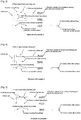

Classifications
-
- H—ELECTRICITY
- H05—ELECTRIC TECHNIQUES NOT OTHERWISE PROVIDED FOR
- H05B—ELECTRIC HEATING; ELECTRIC LIGHT SOURCES NOT OTHERWISE PROVIDED FOR; CIRCUIT ARRANGEMENTS FOR ELECTRIC LIGHT SOURCES, IN GENERAL
- H05B3/00—Ohmic-resistance heating
- H05B3/10—Heating elements characterised by the composition or nature of the materials or by the arrangement of the conductor
- H05B3/12—Heating elements characterised by the composition or nature of the materials or by the arrangement of the conductor characterised by the composition or nature of the conductive material
- H05B3/14—Heating elements characterised by the composition or nature of the materials or by the arrangement of the conductor characterised by the composition or nature of the conductive material the material being non-metallic
-
- H—ELECTRICITY
- H05—ELECTRIC TECHNIQUES NOT OTHERWISE PROVIDED FOR
- H05B—ELECTRIC HEATING; ELECTRIC LIGHT SOURCES NOT OTHERWISE PROVIDED FOR; CIRCUIT ARRANGEMENTS FOR ELECTRIC LIGHT SOURCES, IN GENERAL
- H05B3/00—Ohmic-resistance heating
- H05B3/62—Heating elements specially adapted for furnaces
- H05B3/64—Heating elements specially adapted for furnaces using ribbon, rod, or wire heater
-
- H—ELECTRICITY
- H05—ELECTRIC TECHNIQUES NOT OTHERWISE PROVIDED FOR
- H05B—ELECTRIC HEATING; ELECTRIC LIGHT SOURCES NOT OTHERWISE PROVIDED FOR; CIRCUIT ARRANGEMENTS FOR ELECTRIC LIGHT SOURCES, IN GENERAL
- H05B2203/00—Aspects relating to Ohmic resistive heating covered by group H05B3/00
- H05B2203/017—Manufacturing methods or apparatus for heaters
-
- H—ELECTRICITY
- H05—ELECTRIC TECHNIQUES NOT OTHERWISE PROVIDED FOR
- H05B—ELECTRIC HEATING; ELECTRIC LIGHT SOURCES NOT OTHERWISE PROVIDED FOR; CIRCUIT ARRANGEMENTS FOR ELECTRIC LIGHT SOURCES, IN GENERAL
- H05B2203/00—Aspects relating to Ohmic resistive heating covered by group H05B3/00
- H05B2203/018—Heaters using heating elements comprising mosi2
Definitions
- the present invention relates to an integrated MoSi 2 heating element in which the terminal part and the heat generating part are formed from the same material and which yields effects of being able to achieve greater energy saving than conventional heaters and improve isothermal properties, as well as to a method of producing such a heating element.
- the MoSi 2 plate-shaped heating element used in the present specification includes a heating element containing, as its main component, MoSi 2 that is pure MoSi 2 or MoSi 2 with increased electrical resistance by adding an insulating oxide, such as SiO 2 , to MoSi 2 (normally, MoSi 2 is contained in an amount of 70 wt% or more).
- MoSi 2 molybdenum disilicide
- the heat generating part (normally, the "heat generating part” means the part (other than the terminal part) having a narrow diameter which generates heat when applying current) has a shape making a U (two-shank design), and is mounted in a manner of being suspended in midair from the ceiling or side wall of the furnace, and the maximum allowable working temperature of the furnace reaches 1700 to 1800°C.
- the standard of a commercially available U-shaped heater containing MoSi 2 as its main component is as follows; namely, the wire diameters of the heat generating part and the terminal part are respectively, for example, ⁇ 3/ ⁇ 6, ⁇ 4/ ⁇ 9, ⁇ 6/ ⁇ 12, ⁇ 9/ ⁇ 18, or ⁇ 12/ ⁇ 24.
- the wire diameters of the heat generating part and the terminal part are respectively, for example, ⁇ 3/ ⁇ 6, ⁇ 4/ ⁇ 9, ⁇ 6/ ⁇ 12, ⁇ 9/ ⁇ 18, or ⁇ 12/ ⁇ 24.
- the high resistance part having a narrow diameter becomes a high temperature and assumes the role as a heating unit
- the low resistance part having a thick diameter suppresses heat generation and assumes the role as a terminal part for keeping the feeding part to be a low temperature.
- ' ⁇ ' represents the Stefan-Boltzmann constant
- 'T 1 ' and 'T 2 ' represent the absolute temperature and correspond to the absolute temperature of the heater and the object to be heat-treated in the resistance heating furnace.
- 'A' represents the area
- 'F' represents the view factor.
- the view factor F is a numerical value representing the geometrical relation of two surfaces, and represents a value obtained by sum of the proportions of the radiation that is emitted from all positions on one surface and arrives at the other surface, and is indicated as 0 to 1.
- the absolute temperature of the heater needs to be increased, or the view factor needs to be increased. Nevertheless, when the absolute temperature is increased, more power will be required by that much, and there is no effect from the perspective of energy saving.
- the present inventors considered increasing the area of the heat generating part facing the object to be heat-treated by changing the heat generating part from a conventional rod-shaped (columnar shape) into a plate shape while maintaining the cross-sectional area. If the ratio of the heat generating part line width/terminal part line width is increased from the conventional "0.44 to 0.50" to "0.7 to 1.0", the view factor should increase, and the transmitted thermal energy of radiant energy should increase even with the same surface temperature of the heater. Thus, the present inventors filed a patent application for this plate-shaped MoSi 2 heater. Nevertheless, when extruding a rod shape and thereafter heating and deforming the rod shape into a plate shape (see Patent Document 1), it was extremely difficult to achieve shape stability.
- the terminal part would also become a plate shape, and because there is a need to review the structure of the furnace and specially procure accessories to be used around the terminal part, it was extremely inconvenient to replace the heating element from a conventional rod-shaped heater.
- the terminal part In order to enable the replacement with a conventional product without changing the structure of the furnace or the accessories used around the heater, the terminal part needs to maintain its conventional rod shape. Furthermore, the U-shaped pitch also needs to be kept the same as the commercially available standard.
- the standard U-shaped pitch of the heat generating part is 25 mm ( ⁇ 4 material), 40 mm ( ⁇ 6 material), and 50 mm ( ⁇ 9 material), respectively.
- Patent Document 2 discloses a patent application for an improved invention.
- the foregoing points have been previously described in Patent Document 2, but since they are problems that are also common in the present invention, they have been once again described by way of precaution.
- a U-shaped heater is produced by heating a MoSi 2 material to a high temperature to soften it, and thereafter bending it.
- the bent part is subject to compressive force at the inner part and tensile force at the outer part, and the bent part is in a state with residual strain. This is particularly notable when the diameter of the base material is thick and the U-shaped pitch is narrow.
- the heat generating part is of a plate shape as described above, it is configured to have a width that is substantially the same as the terminal part in order to improve the radiation efficiency.
- the present inventors provide a further improved heating element comprising MoSi 2 and a method of producing such a heating element.
- the present invention is an integrated MoSi 2 based heating element in which the columnar terminal part and the plate-shaped heat generating part are formed from the same material, and provides a U-shaped heater (MoSi 2 based heating element), wherein a rod-shaped wire is bent in a U shape through electrical heating, and thereafter subject to grinding, and only the straight part thereof is used as the plate-shaped heat generating part. Accordingly, since the bent part is not used as the heat generating part, the bent part will not generate heat, or the generation of heat from the bent part can be suppressed, and it is thereby possible to reduce the degradation of such part of the heater and obtain characteristics without any temperature variation.
- a U-shaped heater MoSi 2 based heating element
- the present invention provides a U-shaped heating element comprising MoSi 2 and a method for producing the same, as claimed.
- the present invention provides:
- the present invention is a U-shaped MoSi 2 based heating element (heater), which comprises a columnar terminal part at each end, a bent part, and a plate-shaped heat generating part connecting the columnar terminal parts and the bent part, and can be used with higher efficiency in comparison to conventional heaters.
- the present invention provides a flat heater in which the bent part is not ground to be flat, and only the straight part of the U shape is ground and used as the heat generating part.
- the bent part since the bent part is not subject to grinding, the bent part will not generate heat, or the generation of heat from the bent part can be suppressed, and it is thereby possible to reduce the degradation of such part of the heater and obtain characteristics without any temperature variation.
- a raw material powder of the heating element is mixed with a binder, and the mixture is extruded from a mold to obtain a columnar compact (green). Subsequently, after performing degreasing, the raw material powder is sintered via primary sintering and electrical sintering, and a columnar heating element base material, which is dense and yields favorable straightness, is thereby prepared.
- the structure of the columnar terminal part is the same as conventional products, and an electrode part may be formed at the tip of the columnar terminal part at each end. Accordingly, electricity can be supplied using commercially available accessories.
- a raw material powder of the heating element is mixed with a binder, and the mixture is extruded from a mold to obtain a columnar compact (green).
- the method of producing the columnar compact to be used as the raw material is not necessarily limited to the extrusion method so as long as a columnar compact can be obtained.
- a columnar compact can also be obtained via press molding. Any raw material may be used so as long as a precise sintered compact with high density can be obtained.
- the thus prepared columnar heating element base material may be subject to electrical heating and bent under a high temperature.
- the part (straight part of the U shape) between the columnar terminal part at each end and the bent part, other than the columnar terminal part at each end and the bent part is subject to grinding to form the plate-shaped heat generating part.
- the U-shaped MoSi 2 heating element of the present invention has a structure comprising 1) a columnar terminal part at each end, 2) a bent part, and 3) a plate-shaped heat generating part which connects the columnar terminal parts and (to) the bent part.
- the columnar terminal part is from the edge of the aluminum sprayed part to the end of the inclined surface
- the plate-shaped heat generating part is from the end of the inclined surface of the columnar terminal part to the start of the inclined surface of the bent part
- the bent part is from the start of the inclined surface of the plate-shaped heat generating part on one side to the end of the inclined surface on the other side.
- the plate-shaped heat generating part is not limited to a configuration where both surfaces of the heat generating part have a flat surface, and also includes a configuration where only one surface is a flat surface, and the other surface is a curved surface (semicircular column shape).
- Fig. 2 shows a MoSi 2 heating element in which only one surface, other than the lateral sides, of the plate-shaped heat generating part which connects the columnar terminal parts and the bent part has a flat surface.
- only one surface was subject to grinding. Since the bent part of the MoSi 2 heating element was not subject to grinding and does not have a flat surface shape, the cross-section area of the bent part becomes greater than the cross-section area of the heat generating part, and the heat generation of this part is extremely small, and only the plate-shaped heat generating part is the primary part that generates heat. Thus, the degradation of the bent part is small and, consequently, characteristics without any temperature variation can be obtained.
- a conventional MoSi 2 heating element is shown in Fig. 1 for comparison.
- the bent part is also subject to grinding and thereby has a flat shape.
- the degradation of the bent part of a plate shape becomes severe, and a temperature variation will arise.
- Fig. 3 shows a MoSi 2 heating element in which one lateral side of the plate-shaped heat generating part which connects the bent part and the columnar terminal parts is ground to have a plate width that is narrower than the diameter of the columnar terminal at each end.
- the plate-shaped heat generating part which connects the bent part and the columnar terminal parts has a flat surface, and the bent part was not subject to grinding and does not have a flat surface shape. Therefore, the heat generation of this part is extremely small, and only the plate-shaped heat generating part is the primary part that generates heat.
- the degradation of the bent part is small and, consequently, characteristics without any temperature variation can be obtained.
- Fig. 4 shows a MoSi 2 heating element in which both surfaces of the plate-shaped heat generating part which connects the bent part and the columnar terminal parts have a planar surface (flat surface).
- both surfaces, other than the lateral sides, of the plate-shaped heat generating part which connects the bent part and the columnar terminal parts have a flat surface, and the bent part was not subject to grinding and does not have a flat surface shape. Therefore, the heat generation of this part is extremely small, and only the plate-shaped heat generating part is the primary part that generates heat.
- the degradation of the bent part is small and, consequently, characteristics without any temperature variation can be obtained.
- Fig. 5 shows a MoSi 2 heating element in which both lateral sides of the plate-shaped heat generating part which connects the bent part and the columnar terminal parts are ground to have a plate width that is narrower than the diameter of the columnar terminal part at each end, and both surfaces of the plate-shaped heat generating part which connects the bent part and the columnar terminal parts have a flat surface.
- both surfaces, other than the lateral sides, of the plate-shaped heat generating part which connects the bent part and the columnar terminal parts have a flat surface, and the bent part was not subject to grinding and does not have a flat surface shape. Therefore, this part does not generate heat, and the plate-shaped heat generating part is the only part that generates heat.
- the degradation of the bent part is small and, consequently, characteristics without any temperature variation can be obtained.
- the part between the bent part and the plate-shaped heat generating part, and the part between the plate-shaped heat generating part and the columnar terminal part at each end may be processed to be an inclined surface via grinding. Consequently, the thermal gradient between the respective parts will become moderate, and it is possible to yield the effect of alleviating the burden on the heating element and extending the life of the heating element.
- a MoSi 2 powder and a SiO 2 powder were weighed at a ratio of 94:6 wt%, and mixed and pulverized with a pulverizer to obtain an average grain size of 2 to 5 ⁇ m.
- a binder in an amount of 10 wt% was added thereto, and mixed with a mixer. Subsequently, the mixture was molded into a rod shape using an extruding machine, and this was thereafter subject to degreasing and sintering under an argon atmosphere. This was removed from the furnace and subject to electrical sintering in the atmosphere to obtain a rod material having a diameter ( ⁇ ) of 9 mm.
- the obtained rod material was set in a U-shape bender, and heated to 1500 to 1550°C by applying current, and thereafter bent into a U shape having a pitch of 25 mm.
- a straight part (40 mm), starting from a point that is 20 mm from the tip of the bent part, was ground at a depth of 6.3 mm from one side, and the thickness of that part was made to be 2.7 mm to form a heat generating part.
- the ratio of the cross-section area of the bent part and the columnar terminal part (original rod material) and the cross-section area of the heat generating part (ground part) was caused to be 4:1, but this ratio may also be roughly 3:1.
- the boundary of the columnar terminal part and the heat generating part was ground to have an inclined surface.
- Fig. 2 shows the structure of this Example.
- Fig. 7 shows a state where current is supplied to the heater to generate heat. It is evident that, as intended, the bent part is not generating heat.
- a rod material having a diameter ( ⁇ ) of 9 mm which was produced in the same manner as Example 1 was set in a U-shape bender, and heated to 1500 to 1550°C by applying current, and thereafter bent into a U shape having a pitch of 25 mm.
- the inner side and the outer side of the straight part were respectively ground, at a depth of 0.5 mm, at a length of 67 mm from the tip of the bent part.
- the relation of the width of the columnar terminal part and the width of the heat generating part will be "columnar terminal part > heat generating part".
- effects are yielded in that the edges of the heat generating part in the width direction will not become an acute angle, and thus will not chip easily.
- a straight part (40 mm), starting from a point that is 20 mm from the tip of the bent part, was ground at a depth of 6.2 mm from one side, and the thickness of that part was made to be 2.8 mm to form a heat generating part.
- the ratio of the cross-section area of the columnar terminal part (original rod material) and the cross-section area of the heat generating part (ground part) was caused to be 4:1, but this ratio may also be roughly 3:1.
- the boundary of the columnar terminal part and the heat generating part was ground to have an inclined surface.
- aluminum was thermally sprayed to the end of each columnar terminal part to complete the product.
- Fig. 3 shows the structure of this Example.
- a rod material having a diameter ( ⁇ ) of 9 mm which was produced in the same manner as Example 1 was set in a U-shape bender, and heated to 1500 to 1550°C by applying current, and thereafter bent into a U shape having a pitch of 25 mm.
- the ratio of the cross-section area of the columnar terminal part (original rod material) and the cross-section area of the heat generating part (ground part) was caused to be 4:1, but this ratio may also be roughly 3:1. Furthermore, the boundary of the columnar terminal part and the heat generating part was ground to have an inclined surface. Finally, aluminum was thermally sprayed to the end of each columnar terminal part to complete the product.
- Fig. 4 shows the structure of this Example.
- a rod material having a diameter ( ⁇ ) of 9 mm which was produced in the same manner as Example 1 was set in a U-shape bender, and heated to 1500 to 1550°C by applying current, and thereafter bent into a U shape having a pitch of 25 mm. Only the outer side of the U shape was ground, at a depth of 3.5 mm, at a length of 65 mm from the tip of the bent part, and the width of the heat generating part was caused to be narrower than the width of the columnar terminal part.
- a straight part (40 mm), starting from a point that is 20 mm from the tip of the bent part, was ground at a depth of 3.0 mm from both sides, and the thickness of that part was made to be 3.0 mm to form a heat generating part.
- the ratio of the cross-section area of the columnar terminal part (original rod material) and the cross-section area of the heat generating part (ground part) was caused to be 4:1, but this ratio may also be roughly 3:1.
- the boundary of the columnar terminal part and the heat generating part was ground to have an inclined surface.
- aluminum was thermally sprayed to the end of each columnar terminal part to complete the product.
- Fig. 5 shows the structure of this Example.
- a rod material having a diameter ( ⁇ ) of 9 mm which was produced in the same manner as Example 1 was set in a U-shape bender, and heated to 1500 to 1550°C by applying current, and thereafter bent into a U shape having a pitch of 25 mm.
- a part at a length of 100 mm from the tip of the bent part was ground at a depth of 6.3 mm from one side, and the thickness of that part was made to be 2.7 mm to form a heat generating part. Since grinding is performed only from one side, the relation of the width of the columnar terminal part and the width of the heat generating part will be "columnar terminal part > heat generating part".
- the ratio of the cross-section area of the columnar terminal part (original rod material) and the cross-section area of the heat generating part (ground part) was caused to be 4:1. Furthermore, the boundary of the columnar terminal part and the heat generating part was ground to have an inclined surface.
- Fig. 1 shows the structure of this Comparative Example.
- Fig. 6 shows a state where current is supplied to the heater to generate heat.
- the tip of the bent part is dark. This shows that the temperature of the tip of the bent part is low, and that there is a temperature variation in the heat generating part.
- the tip of the bent part was warped toward the furnace side.
- the present invention is a U-shaped MoSi 2 based heating element comprising a columnar terminal part at each end, a bent part, and a plate-shaped heat generating part which connects the columnar terminal parts and the bent part, wherein a cross-section area of the bent part is greater than a cross-section area of the plate-shaped heat generating part. Furthermore, the present invention is a method of producing a U-shaped MoSi 2 based heating element, wherein a columnar MoSi 2 raw material is bent into a U shape, and a straight part is ground, with a bent part left unground, to have a flat surface, and used as the heat generating part.
- the bent part of the U-shaped MoSi 2 based heating element is not ground, the bent part will not generate heat, or the generation of heat from the bent part can be suppressed, and it is thereby possible to reduce the degradation of such part of the heater, uniformly radiate and heat the object to be heat-treated, and obtain characteristics without any temperature variation. Accordingly, high temperature heating with low energy is enabled, and the present invention is particularly useful as a heater for use in an electrical furnace or the like.
Landscapes
- Resistance Heating (AREA)
Abstract
Description
- The present invention relates to an integrated MoSi2 heating element in which the terminal part and the heat generating part are formed from the same material and which yields effects of being able to achieve greater energy saving than conventional heaters and improve isothermal properties, as well as to a method of producing such a heating element.
- Note that the MoSi2 plate-shaped heating element used in the present specification includes a heating element containing, as its main component, MoSi2 that is pure MoSi2 or MoSi2 with increased electrical resistance by adding an insulating oxide, such as SiO2, to MoSi2 (normally, MoSi2 is contained in an amount of 70 wt% or more).
- Since a heating element containing molybdenum disilicide (MoSi2) as its main component yields superior oxidation-resistant characteristics, it was commercialized from around the 1950s as an ultrahigh temperature heating element for use particularly in the atmosphere or under an oxidizing atmosphere, and is still widely used today. This heating element contains, as its main component, MoSi2 in an amount of 70 wt% or more.
- Conventionally, with a heating element that is widely used in various fields such as the glass industry and ceramic calcination, as shown in
Fig. 8 , the heat generating part (normally, the "heat generating part" means the part (other than the terminal part) having a narrow diameter which generates heat when applying current) has a shape making a U (two-shank design), and is mounted in a manner of being suspended in midair from the ceiling or side wall of the furnace, and the maximum allowable working temperature of the furnace reaches 1700 to 1800°C. - Today, the standard of a commercially available U-shaped heater containing MoSi2 as its main component is as follows; namely, the wire diameters of the heat generating part and the terminal part are respectively, for example, ϕ3/ϕ6, ϕ4/ϕ9, ϕ6/ϕ12, ϕ9/ϕ18, or ϕ12/ϕ24. This is because, with a MoSi2 heater, since the heat generating part and the terminal part basically have the same composition, it is necessary to control the amount of heat generation by changing the electrical resistance based on the element wire diameter (cross-sectional area). Accordingly, when current is applied to the heater, the high resistance part having a narrow diameter becomes a high temperature and assumes the role as a heating unit, and the low resistance part having a thick diameter suppresses heat generation and assumes the role as a terminal part for keeping the feeding part to be a low temperature.
- There are three modes of heat transfer; namely, heat conduction, heat convection, and heat radiation, but it is said that the ratio of heat radiation from the heater is high in the heat transfer to the object to be heat-treated in a resistance heating furnace. The transmitted thermal energy Q of radiant energy is expressed with the formula of Q = σ(T1 4-T2 4)•A•F. Here, 'σ' represents the Stefan-Boltzmann constant, and 'T1' and 'T2' represent the absolute temperature and correspond to the absolute temperature of the heater and the object to be heat-treated in the resistance heating furnace. Furthermore, 'A' represents the area, and 'F' represents the view factor.
- The view factor F is a numerical value representing the geometrical relation of two surfaces, and represents a value obtained by sum of the proportions of the radiation that is emitted from all positions on one surface and arrives at the other surface, and is indicated as 0 to 1.
- Accordingly, in order to increase the transmitted thermal energy Q of radiant energy to the object to be heat-treated having the same surface area in a resistance heating furnace, the absolute temperature of the heater needs to be increased, or the view factor needs to be increased. Nevertheless, when the absolute temperature is increased, more power will be required by that much, and there is no effect from the perspective of energy saving.
- Meanwhile, if it is possible to increase the ratio of radiation emitted from the heater that reaches the object to be heat-treated; that is, if it is possible to increase the view factor, effective heat transfer to the object to be heat-treated can be achieved and energy saving will be achieved thereby.
- Thus, the present inventors considered increasing the area of the heat generating part facing the object to be heat-treated by changing the heat generating part from a conventional rod-shaped (columnar shape) into a plate shape while maintaining the cross-sectional area. If the ratio of the heat generating part line width/terminal part line width is increased from the conventional "0.44 to 0.50" to "0.7 to 1.0", the view factor should increase, and the transmitted thermal energy of radiant energy should increase even with the same surface temperature of the heater. Thus, the present inventors filed a patent application for this plate-shaped MoSi2 heater. Nevertheless, when extruding a rod shape and thereafter heating and deforming the rod shape into a plate shape (see Patent Document 1), it was extremely difficult to achieve shape stability.
- Furthermore, when extruding a belt shape (plate shape) from the beginning, the terminal part would also become a plate shape, and because there is a need to review the structure of the furnace and specially procure accessories to be used around the terminal part, it was extremely inconvenient to replace the heating element from a conventional rod-shaped heater.
- Furthermore, with the method of extruding the heat generating part in a plate shape and bonding it with a rod-shaped terminal part, there was a problem in that the welding is unstable. Due to the foregoing circumstances, a heater demanded in recent years is a heater that has superior shape stability, is free from problems of the welded part, and can be easily replaced with an existing heater.
- In order to enable the replacement with a conventional product without changing the structure of the furnace or the accessories used around the heater, the terminal part needs to maintain its conventional rod shape. Furthermore, the U-shaped pitch also needs to be kept the same as the commercially available standard. Today, in a commercially available heater in which the diameters of the heat generating part and the terminal part are respectively ϕ4/ϕ9, ϕ6/ϕ12, or ϕ9/ϕ18, the standard U-shaped pitch of the heat generating part is 25 mm (ϕ4 material), 40 mm (ϕ6 material), and 50 mm (ϕ9 material), respectively.
- When attempting to bend this part through electrical heating by using materials having a thick terminal part; namely, 25 mm (ϕ9 material), 40 mm (ϕ12 material), and 50 mm (ϕ18 material), conventionally the wire would break or, even if bent, the bent part would become cracked and the processing was extremely difficult, and thus such processing was not performed. Furthermore, even if it was possible to bend the material into a U shape, it is difficult for the bent part to be placed on the same flat surface, and if the heat generating part is ground as is, there will be variation in the thickness, and it was difficult to produce a heater capable of uniform heat generation.
- Accordingly, the Applicant filed a patent application for an improved invention (see Patent Document 2). The foregoing points have been previously described in
Patent Document 2, but since they are problems that are also common in the present invention, they have been once again described by way of precaution. - A U-shaped heater is produced by heating a MoSi2 material to a high temperature to soften it, and thereafter bending it. Here, the bent part is subject to compressive force at the inner part and tensile force at the outer part, and the bent part is in a state with residual strain. This is particularly notable when the diameter of the base material is thick and the U-shaped pitch is narrow.
- In the case of a heater that is produced by bending a MoSi2, which has the same diameter as the terminal part, into a U shape, and grinding the heat generating part into a plate shape, the foregoing production conditions will apply, and it is likely that the bent part will have residual strain. And when the heater is used in this kind of state, there are problems in that it is likely that the bent part with residual strain will break, or the bent part will become warped backward/forward, and this will considerably influence the life of the heater.
- Furthermore, when the heat generating part is of a plate shape as described above, it is configured to have a width that is substantially the same as the terminal part in order to improve the radiation efficiency. Here, the inner part and the outer part of the bent part will be subject to a distance difference in the current path (= difference in resistance value). This will lead to a temperature difference between the inner part and the outer part of the bent part. In other words, the temperature distribution will be high at the inner part and low at the outer part, and the uniform heating characteristics of the heater will deteriorate.
- In light of the foregoing points, the present inventors provide a further improved heating element comprising MoSi2 and a method of producing such a heating element.
-
- [Patent Document 1]
JP 3947661 B - [Patent Document 2]
JP 2011-090801 A - The present invention is an integrated MoSi2 based heating element in which the columnar terminal part and the plate-shaped heat generating part are formed from the same material, and provides a U-shaped heater (MoSi2 based heating element), wherein a rod-shaped wire is bent in a U shape through electrical heating, and thereafter subject to grinding, and only the straight part thereof is used as the plate-shaped heat generating part. Accordingly, since the bent part is not used as the heat generating part, the bent part will not generate heat, or the generation of heat from the bent part can be suppressed, and it is thereby possible to reduce the degradation of such part of the heater and obtain characteristics without any temperature variation.
- In order to achieve the foregoing object, the present invention provides a U-shaped heating element comprising MoSi2 and a method for producing the same, as claimed.
- Specifically, the present invention provides:
- 1) A U-shaped heating element comprising MoSi2, the heating element comprising a columnar terminal part at each end, a bent part, and a plate-shaped heat generating part which connects the columnar terminal parts and the bent part, wherein a cross-sectional area of the bent part is greater than a cross-sectional area of the plate-shaped heat generating part.
- 2) The heating element according to 1), wherein the bent part is of a columnar shape.
- 3) The heating element according to 1) or 2), wherein one surface of the plate-shaped heat generating part comprises a ground surface.
- 4) The heating element according to 1) or 2), wherein both surfaces of the plate-shaped heat generating part comprise a ground surface.
- 5) The heating element according to any one of 1) to 4), wherein a plate width of the plate-shaped heat generating part is smaller than a diameter of the columnar terminal parts.
- 6) The heating element according to 5), wherein one lateral side of the plate-shaped heat generating part has a plate width that is narrower than the diameter of the columnar terminal at each end.
- 7) The heating element according to 5), wherein both lateral sides of the plate-shaped heat generating part have a plate width that is narrower than the diameter of the columnar terminal at each end.
- 8) The heating element according to any one of 1) to 7), wherein a part of the columnar terminal part and/or a part of the bent part comprises an inclined surface formed via grinding.
- 9) A method of producing a U-shaped heating element comprising MoSi2, wherein a columnar MoSi2 raw material is bent into a U shape, and an area to become a heat generating part is thereafter ground, with a bent part left unground, to have a plate shape.
- 10)The method of producing a heating element according to 9), wherein a cross-sectional area of the bent part is greater than a cross-sectional area of the plate-shaped heat generating part.
- 11)The method of producing a heating element according to 9) or 10), wherein the unground bent part is of a columnar shape.
- 12)The method of producing a heating element according to 9), 10) or 11), wherein, in the process of grinding the area to become the heat generating part after bending the columnar MoSi2 raw material into a U shape, grinding is started from one side of a curved surface of a MoSi2 column, and the area is processed so that one surface of the plate-shaped heat generating part have a flat surface and another surface of the plate-shaped heat generating part remains to have a columnar curved surface.
- 13)The method of producing a heating element according to 9), 10) or 11), wherein, in the process of grinding the area to become the heat generating part after bending the columnar MoSi2 raw material into a U shape, both sides of a curved surface of a MoSi2 column are ground, and the area is processed so that both surfaces of the plate-shaped heat generating part connecting the bent part and the columnar terminal parts have a flat surface.
- 14)The method of producing a heating element according to any one of 9) to 13), wherein one lateral side or both lateral sides of the plate-shaped heat generating part connecting the bent part and the columnar terminal parts are ground so as to have a plate width that is narrower than a diameter of the columnar terminal part at each end.
- 15)The method of producing a heating element according to any one of 9) to 14), wherein a part between the bent part and the plate-shaped heat generating part, and a part between the plate-shaped heat generating part and the columnar terminal part at each end, are processed into an inclined surface via grinding.
- The present invention is a U-shaped MoSi2 based heating element (heater), which comprises a columnar terminal part at each end, a bent part, and a plate-shaped heat generating part connecting the columnar terminal parts and the bent part, and can be used with higher efficiency in comparison to conventional heaters. As evident from the above, the present invention provides a flat heater in which the bent part is not ground to be flat, and only the straight part of the U shape is ground and used as the heat generating part.
- Accordingly, since the bent part is not subject to grinding, the bent part will not generate heat, or the generation of heat from the bent part can be suppressed, and it is thereby possible to reduce the degradation of such part of the heater and obtain characteristics without any temperature variation.
-
- [
Fig. 1 ] This is a schematic diagram showing an example of a conventional integrated MoSi2 plate-shaped heating element in which a columnar terminal part and a plate-shaped heat generating part are formed from the same material, wherein the heat generating part has a plate shape and the terminal part has a columnar shape. - [
Fig. 2 ] This is a schematic diagram showing a representative example of the U-shaped MoSi2 heating element of the present invention comprising a columnar terminal part at each end, a bent part, and a plate-shaped heat generating part which connects the columnar terminal parts and the bent part. - [
Fig. 3 ] This is a schematic diagram of a U-shaped MoSi2 heating element having a columnar terminal part at each end, a bent part, and a plate-shaped heat generating part which connects the columnar terminal parts and the bent part, wherein the plate-shaped heat generating part which connects the columnar terminal parts and the bent part has a plate width that is narrower than the diameter of the columnar terminal part at each end. - [
Fig. 4 ] This is a schematic diagram showing a representative example of a U-shaped MoSi2 heating element having a columnar terminal part at each end, a bent part, and a plate-shaped heat generating part which connects the columnar terminal parts and the bent part, wherein both surfaces of the plate-shaped heat generating part which connects the columnar terminal parts and the bent part have a flat surface (see cross-section views - both the upper and lower surfaces in cross-section are flat). - [
Fig. 5 ] This is a schematic diagram showing a representative example of a U-shaped MoSi2 heating element having a columnar terminal part at each end, a bent part, and a plate-shaped heat generating part which connects the columnar terminal parts and the bent part, wherein both surfaces of the plate-shaped heat generating part which connects the columnar terminal parts and the bent part have a flat surface (see cross-section views - both the upper and lower surfaces in cross-section are flat), and the plate-shaped heat generating part has a plate width that is narrower than the diameter of the columnar terminal part at each end. - [
Fig. 6 ] This is a photograph showing the electrical heating state of a conventional MoSi2 plate-shaped heating element in which a columnar terminal part and a plate-shaped heat generating part are formed from the same material, wherein the heat generating part has a plate shape and the terminal part has a columnar shape. - [
Fig. 7 ] This is a photograph showing the electrical heating state of the U-shaped MoSi2 heating element of the present invention comprising a columnar terminal part at each end, a bent part, and a plate-shaped heat generating part which connects the columnar terminal parts and the bent part. - [
Fig. 8 ] This is a schematic diagram showing a heat generating part and a terminal part of a standard U-shaped heater. - In order to produce the MoSi2 plate-shaped heating element of the present invention, foremost, a raw material powder of the heating element is mixed with a binder, and the mixture is extruded from a mold to obtain a columnar compact (green). Subsequently, after performing degreasing, the raw material powder is sintered via primary sintering and electrical sintering, and a columnar heating element base material, which is dense and yields favorable straightness, is thereby prepared.
- The structure of the columnar terminal part is the same as conventional products, and an electrode part may be formed at the tip of the columnar terminal part at each end. Accordingly, electricity can be supplied using commercially available accessories.
- In this example, a raw material powder of the heating element is mixed with a binder, and the mixture is extruded from a mold to obtain a columnar compact (green). Nevertheless, it should be easy to understand that the method of producing the columnar compact to be used as the raw material is not necessarily limited to the extrusion method so as long as a columnar compact can be obtained. For example, a columnar compact can also be obtained via press molding. Any raw material may be used so as long as a precise sintered compact with high density can be obtained.
- The thus prepared columnar heating element base material may be subject to electrical heating and bent under a high temperature. After the columnar MoSi2 heating element base material is bent into a U shape at a predetermined pitch, the part (straight part of the U shape) between the columnar terminal part at each end and the bent part, other than the columnar terminal part at each end and the bent part, is subject to grinding to form the plate-shaped heat generating part. In other words, the U-shaped MoSi2 heating element of the present invention has a structure comprising 1) a columnar terminal part at each end, 2) a bent part, and 3) a plate-shaped heat generating part which connects the columnar terminal parts and (to) the bent part. Specifically, the columnar terminal part is from the edge of the aluminum sprayed part to the end of the inclined surface, the plate-shaped heat generating part is from the end of the inclined surface of the columnar terminal part to the start of the inclined surface of the bent part, and the bent part is from the start of the inclined surface of the plate-shaped heat generating part on one side to the end of the inclined surface on the other side.
- Note that the plate-shaped heat generating part is not limited to a configuration where both surfaces of the heat generating part have a flat surface, and also includes a configuration where only one surface is a flat surface, and the other surface is a curved surface (semicircular column shape).
-
Fig. 2 shows a MoSi2 heating element in which only one surface, other than the lateral sides, of the plate-shaped heat generating part which connects the columnar terminal parts and the bent part has a flat surface. In other words, only one surface was subject to grinding. Since the bent part of the MoSi2 heating element was not subject to grinding and does not have a flat surface shape, the cross-section area of the bent part becomes greater than the cross-section area of the heat generating part, and the heat generation of this part is extremely small, and only the plate-shaped heat generating part is the primary part that generates heat. Thus, the degradation of the bent part is small and, consequently, characteristics without any temperature variation can be obtained. - Incidentally, a conventional MoSi2 heating element is shown in
Fig. 1 for comparison. InFig. 1 , the bent part is also subject to grinding and thereby has a flat shape. Thus, there are problems in that the degradation of the bent part of a plate shape becomes severe, and a temperature variation will arise. -
Fig. 3 shows a MoSi2 heating element in which one lateral side of the plate-shaped heat generating part which connects the bent part and the columnar terminal parts is ground to have a plate width that is narrower than the diameter of the columnar terminal at each end. In the foregoing case, as withFig. 2 , only one surface, other than the lateral sides, of the plate-shaped heat generating part which connects the bent part and the columnar terminal parts has a flat surface, and the bent part was not subject to grinding and does not have a flat surface shape. Therefore, the heat generation of this part is extremely small, and only the plate-shaped heat generating part is the primary part that generates heat. Thus, as withFig. 2 , the degradation of the bent part is small and, consequently, characteristics without any temperature variation can be obtained. -
Fig. 4 shows a MoSi2 heating element in which both surfaces of the plate-shaped heat generating part which connects the bent part and the columnar terminal parts have a planar surface (flat surface). In the foregoing case also, as withFig. 2 , both surfaces, other than the lateral sides, of the plate-shaped heat generating part which connects the bent part and the columnar terminal parts have a flat surface, and the bent part was not subject to grinding and does not have a flat surface shape. Therefore, the heat generation of this part is extremely small, and only the plate-shaped heat generating part is the primary part that generates heat. Thus, as withFig. 2 , the degradation of the bent part is small and, consequently, characteristics without any temperature variation can be obtained. -
Fig. 5 shows a MoSi2 heating element in which both lateral sides of the plate-shaped heat generating part which connects the bent part and the columnar terminal parts are ground to have a plate width that is narrower than the diameter of the columnar terminal part at each end, and both surfaces of the plate-shaped heat generating part which connects the bent part and the columnar terminal parts have a flat surface. In the foregoing case also, as withFig. 2 , both surfaces, other than the lateral sides, of the plate-shaped heat generating part which connects the bent part and the columnar terminal parts have a flat surface, and the bent part was not subject to grinding and does not have a flat surface shape. Therefore, this part does not generate heat, and the plate-shaped heat generating part is the only part that generates heat. Thus, as withFig. 2 , the degradation of the bent part is small and, consequently, characteristics without any temperature variation can be obtained. - Furthermore, as needed, the part between the bent part and the plate-shaped heat generating part, and the part between the plate-shaped heat generating part and the columnar terminal part at each end, may be processed to be an inclined surface via grinding. Consequently, the thermal gradient between the respective parts will become moderate, and it is possible to yield the effect of alleviating the burden on the heating element and extending the life of the heating element.
- The Examples of the present invention are now explained. Note that these Examples are provided for facilitating the understanding of the invention, and it should be understood that the present invention is not limited to the ensuing Examples.
- A MoSi2 powder and a SiO2 powder were weighed at a ratio of 94:6 wt%, and mixed and pulverized with a pulverizer to obtain an average grain size of 2 to 5 µm. A binder in an amount of 10 wt% was added thereto, and mixed with a mixer. Subsequently, the mixture was molded into a rod shape using an extruding machine, and this was thereafter subject to degreasing and sintering under an argon atmosphere. This was removed from the furnace and subject to electrical sintering in the atmosphere to obtain a rod material having a diameter (ϕ) of 9 mm.
- Subsequently, the obtained rod material was set in a U-shape bender, and heated to 1500 to 1550°C by applying current, and thereafter bent into a U shape having a pitch of 25 mm. A straight part (40 mm), starting from a point that is 20 mm from the tip of the bent part, was ground at a depth of 6.3 mm from one side, and the thickness of that part was made to be 2.7 mm to form a heat generating part. Note that, based on the foregoing grinding, the ratio of the cross-section area of the bent part and the columnar terminal part (original rod material) and the cross-section area of the heat generating part (ground part) was caused to be 4:1, but this ratio may also be roughly 3:1. Furthermore, the boundary of the columnar terminal part and the heat generating part was ground to have an inclined surface.
- Finally, aluminum was thermally sprayed to the end of each columnar terminal part to complete the product.
Fig. 2 shows the structure of this Example.Fig. 7 shows a state where current is supplied to the heater to generate heat. It is evident that, as intended, the bent part is not generating heat. - A rod material having a diameter (ϕ) of 9 mm which was produced in the same manner as Example 1 was set in a U-shape bender, and heated to 1500 to 1550°C by applying current, and thereafter bent into a U shape having a pitch of 25 mm. The inner side and the outer side of the straight part were respectively ground, at a depth of 0.5 mm, at a length of 67 mm from the tip of the bent part. As a result of grinding both of the inner side and the outer side, the relation of the width of the columnar terminal part and the width of the heat generating part will be "columnar terminal part > heat generating part". Furthermore, as a result of grinding both of the inner side and the outer side, effects are yielded in that the edges of the heat generating part in the width direction will not become an acute angle, and thus will not chip easily.
- Subsequently, a straight part (40 mm), starting from a point that is 20 mm from the tip of the bent part, was ground at a depth of 6.2 mm from one side, and the thickness of that part was made to be 2.8 mm to form a heat generating part. Note that, based on the foregoing grinding, the ratio of the cross-section area of the columnar terminal part (original rod material) and the cross-section area of the heat generating part (ground part) was caused to be 4:1, but this ratio may also be roughly 3:1. Furthermore, the boundary of the columnar terminal part and the heat generating part was ground to have an inclined surface. Finally, aluminum was thermally sprayed to the end of each columnar terminal part to complete the product.
Fig. 3 shows the structure of this Example. - A rod material having a diameter (ϕ) of 9 mm which was produced in the same manner as Example 1 was set in a U-shape bender, and heated to 1500 to 1550°C by applying current, and thereafter bent into a U shape having a pitch of 25 mm. A straight part (40 mm), starting from a point that is 20 mm from the tip of the bent part, was ground at a depth of 3.5 mm from both sides, and the thickness of that part was made to be 2.0 mm to form a heat generating part. Since grinding was performed from both sides at the same depth, the width of the columnar terminal part and the width of the heat generating part will be the same. Note that, based on the foregoing grinding, the ratio of the cross-section area of the columnar terminal part (original rod material) and the cross-section area of the heat generating part (ground part) was caused to be 4:1, but this ratio may also be roughly 3:1. Furthermore, the boundary of the columnar terminal part and the heat generating part was ground to have an inclined surface. Finally, aluminum was thermally sprayed to the end of each columnar terminal part to complete the product.
Fig. 4 shows the structure of this Example. - A rod material having a diameter (ϕ) of 9 mm which was produced in the same manner as Example 1 was set in a U-shape bender, and heated to 1500 to 1550°C by applying current, and thereafter bent into a U shape having a pitch of 25 mm. Only the outer side of the U shape was ground, at a depth of 3.5 mm, at a length of 65 mm from the tip of the bent part, and the width of the heat generating part was caused to be narrower than the width of the columnar terminal part. Subsequently, a straight part (40 mm), starting from a point that is 20 mm from the tip of the bent part, was ground at a depth of 3.0 mm from both sides, and the thickness of that part was made to be 3.0 mm to form a heat generating part. Note that, based on the foregoing grinding, the ratio of the cross-section area of the columnar terminal part (original rod material) and the cross-section area of the heat generating part (ground part) was caused to be 4:1, but this ratio may also be roughly 3:1. Furthermore, the boundary of the columnar terminal part and the heat generating part was ground to have an inclined surface. Finally, aluminum was thermally sprayed to the end of each columnar terminal part to complete the product.
Fig. 5 shows the structure of this Example. - A rod material having a diameter (ϕ) of 9 mm which was produced in the same manner as Example 1 was set in a U-shape bender, and heated to 1500 to 1550°C by applying current, and thereafter bent into a U shape having a pitch of 25 mm. A part at a length of 100 mm from the tip of the bent part was ground at a depth of 6.3 mm from one side, and the thickness of that part was made to be 2.7 mm to form a heat generating part. Since grinding is performed only from one side, the relation of the width of the columnar terminal part and the width of the heat generating part will be "columnar terminal part > heat generating part". Based on this grinding, the ratio of the cross-section area of the columnar terminal part (original rod material) and the cross-section area of the heat generating part (ground part) was caused to be 4:1. Furthermore, the boundary of the columnar terminal part and the heat generating part was ground to have an inclined surface.
- Finally, aluminum was thermally sprayed to the end of each columnar terminal part to complete the product.
Fig. 1 shows the structure of this Comparative Example. Furthermore,Fig. 6 shows a state where current is supplied to the heater to generate heat. Upon comparing the bent part and the straight part, the tip of the bent part is dark. This shows that the temperature of the tip of the bent part is low, and that there is a temperature variation in the heat generating part. Furthermore, upon observing the state of the heating element after heating it to a furnace temperature of 1500°C and cooling it to room temperature, there was a problem in that the tip of the bent part was warped toward the furnace side. - The present invention is a U-shaped MoSi2 based heating element comprising a columnar terminal part at each end, a bent part, and a plate-shaped heat generating part which connects the columnar terminal parts and the bent part, wherein a cross-section area of the bent part is greater than a cross-section area of the plate-shaped heat generating part. Furthermore, the present invention is a method of producing a U-shaped MoSi2 based heating element, wherein a columnar MoSi2 raw material is bent into a U shape, and a straight part is ground, with a bent part left unground, to have a flat surface, and used as the heat generating part.
- As described above, with the present invention, since the bent part of the U-shaped MoSi2 based heating element is not ground, the bent part will not generate heat, or the generation of heat from the bent part can be suppressed, and it is thereby possible to reduce the degradation of such part of the heater, uniformly radiate and heat the object to be heat-treated, and obtain characteristics without any temperature variation. Accordingly, high temperature heating with low energy is enabled, and the present invention is particularly useful as a heater for use in an electrical furnace or the like.
-
- 1: Columnar terminal part
- 2: Plate-shaped heat generating part
- 3: Inclined surface formed via grinding
- 4: Bent part
- 5: Ground surface (flat surface)
- 6: Unground surface (columnar curved surface)
- 7: Structure capable of connecting to feeding part (aluminum sprayed part)
- 8: Lateral side grinding
- When used in this specification and claims, the terms "comprises" and "comprising" and variations thereof mean that the specified features, steps or integers are included. The terms are not to be interpreted to exclude the presence of other features, steps or components.
- The features disclosed in the foregoing description, or the following claims, or the accompanying drawings, expressed in their specific forms or in terms of a means for performing the disclosed function, or a method or process for attaining the disclosed result, as appropriate, may, separately, or in any combination of such features, be utilised for realising the invention in diverse forms thereof. In particular, one or more features in any of the embodiments described herein may be combined with one or more features from any other embodiments described herein.
Claims (15)
- A U-shaped heating element comprising MoSi2, the heating element comprising a columnar terminal part at each end, a bent part, and a plate-shaped heat generating part which connects the columnar terminal parts and the bent part, wherein a cross-sectional area of the bent part is greater than a cross-sectional area of the plate-shaped heat generating part.
- The heating element according to claim 1, wherein the bent part is of a columnar shape.
- The heating element according to claim 1 or 2, wherein one surface of the plate-shaped heat generating part comprises a ground surface.
- The heating element according to claim 1 or 2, wherein both surfaces of the plate-shaped heat generating part comprise a ground surface.
- The heating element according to any one of claims 1 to 4, wherein a plate width of the plate-shaped heat generating part is smaller than a diameter of the columnar terminal parts.
- The heating element according to claim 5, wherein one lateral side of the plate-shaped heat generating part has a plate width that is narrower than the diameter of the columnar terminal at each end.
- The heating element according to claim 5, wherein both lateral sides of the plate-shaped heat generating part have a plate width that is narrower than the diameter of the columnar terminal at each end.
- The heating element according to any one of claims 1 to 7, wherein a part of the columnar terminal part and/or a part of the bent part comprises an inclined surface formed via grinding.
- A method of producing a U-shaped heating element comprising MoSi2, wherein a columnar MoSi2 raw material is bent into a U shape, and an area to become a heat generating part is thereafter ground, with a bent part left unground, to have a plate shape.
- The method of producing a heating element according to claim 9, wherein a cross-sectional area of the bent part is greater than a cross-sectional area of the plate-shaped heat generating part.
- The method of producing a heating element according to claim 9 or 10, wherein the unground bent part is of a columnar shape.
- The method of producing a heating element according to claim 9, 10 or 11, wherein, in the process of grinding the area to become the heat generating part after bending the columnar MoSi2 raw material into a U shape, grinding is started from one side of a curved surface of a MoSi2 column, and the area is processed so that one surface of the plate-shaped heat generating part have a flat surface and another surface of the plate-shaped heat generating part remains to have a columnar curved surface.
- The method of producing a heating element according to claim 9, 10 or 11, wherein, in the process of grinding the area to become the heat generating part after bending the columnar MoSi2 raw material into a U shape, both sides of a curved surface of a MoSi2 column are ground, and the area is processed so that both surfaces of the plate-shaped heat generating part connecting the bent part and the columnar terminal parts have a flat surface.
- The method of producing a heating element according to any one of claims 9 to 13, wherein one lateral side or both lateral sides of the plate-shaped heat generating part connecting the bent part and the columnar terminal parts are ground so as to have a plate width that is narrower than a diameter of the columnar terminal part at each end.
- The method of producing a heating element according to any one of claims 9 to 14, wherein a part between the bent part and the plate-shaped heat generating part, and a part between the plate-shaped heat generating part and the columnar terminal part at each end, are processed into an inclined surface via grinding.
Applications Claiming Priority (1)
| Application Number | Priority Date | Filing Date | Title |
|---|---|---|---|
| JP2016013085A JP6590319B2 (en) | 2016-01-27 | 2016-01-27 | MoSi2 heating element and method of manufacturing the same |
Publications (2)
| Publication Number | Publication Date |
|---|---|
| EP3200558A1 true EP3200558A1 (en) | 2017-08-02 |
| EP3200558B1 EP3200558B1 (en) | 2019-05-08 |
Family
ID=57909499
Family Applications (1)
| Application Number | Title | Priority Date | Filing Date |
|---|---|---|---|
| EP17153303.7A Active EP3200558B1 (en) | 2016-01-27 | 2017-01-26 | Mosi2 heating element and method of producing said heating element |
Country Status (2)
| Country | Link |
|---|---|
| EP (1) | EP3200558B1 (en) |
| JP (1) | JP6590319B2 (en) |
Cited By (1)
| Publication number | Priority date | Publication date | Assignee | Title |
|---|---|---|---|---|
| EP4412397A4 (en) * | 2022-01-26 | 2025-12-10 | Jx Metals Corp | MOSI2 heater |
Families Citing this family (1)
| Publication number | Priority date | Publication date | Assignee | Title |
|---|---|---|---|---|
| CN111869317B (en) * | 2018-03-18 | 2022-06-14 | 山特维克知识产权股份有限公司 | Heating element comprising chromium-alloyed molybdenum disilicide and use thereof |
Citations (6)
| Publication number | Priority date | Publication date | Assignee | Title |
|---|---|---|---|---|
| JPH076865A (en) * | 1993-06-15 | 1995-01-10 | Nippondenso Co Ltd | Ceramic heater element |
| EP1734304A1 (en) * | 2004-04-07 | 2006-12-20 | Ngk Spark Plug Co., Ltd. | Ceramic heater and manufacturing method thereof, and glow plug using ceramic heater |
| JP3947661B2 (en) | 2001-10-01 | 2007-07-25 | 日鉱金属株式会社 | MoSi2 plate heater |
| JP2011090801A (en) | 2009-10-20 | 2011-05-06 | Jx Nippon Mining & Metals Corp | MoSi2 HEATING ELEMENT AND MANUFACTURING METHOD OF THIS HEATING ELEMENT |
| EP2343951A1 (en) * | 2008-10-28 | 2011-07-13 | Kyocera Corporation | Ceramic heater |
| JP2014160673A (en) * | 2014-04-30 | 2014-09-04 | Jx Nippon Mining & Metals Corp | MoSi2 heating element and method of manufacturing the same |
-
2016
- 2016-01-27 JP JP2016013085A patent/JP6590319B2/en active Active
-
2017
- 2017-01-26 EP EP17153303.7A patent/EP3200558B1/en active Active
Patent Citations (6)
| Publication number | Priority date | Publication date | Assignee | Title |
|---|---|---|---|---|
| JPH076865A (en) * | 1993-06-15 | 1995-01-10 | Nippondenso Co Ltd | Ceramic heater element |
| JP3947661B2 (en) | 2001-10-01 | 2007-07-25 | 日鉱金属株式会社 | MoSi2 plate heater |
| EP1734304A1 (en) * | 2004-04-07 | 2006-12-20 | Ngk Spark Plug Co., Ltd. | Ceramic heater and manufacturing method thereof, and glow plug using ceramic heater |
| EP2343951A1 (en) * | 2008-10-28 | 2011-07-13 | Kyocera Corporation | Ceramic heater |
| JP2011090801A (en) | 2009-10-20 | 2011-05-06 | Jx Nippon Mining & Metals Corp | MoSi2 HEATING ELEMENT AND MANUFACTURING METHOD OF THIS HEATING ELEMENT |
| JP2014160673A (en) * | 2014-04-30 | 2014-09-04 | Jx Nippon Mining & Metals Corp | MoSi2 heating element and method of manufacturing the same |
Cited By (1)
| Publication number | Priority date | Publication date | Assignee | Title |
|---|---|---|---|---|
| EP4412397A4 (en) * | 2022-01-26 | 2025-12-10 | Jx Metals Corp | MOSI2 heater |
Also Published As
| Publication number | Publication date |
|---|---|
| JP2017134968A (en) | 2017-08-03 |
| JP6590319B2 (en) | 2019-10-16 |
| EP3200558B1 (en) | 2019-05-08 |
Similar Documents
| Publication | Publication Date | Title |
|---|---|---|
| CN110577399B (en) | Multi-field coupling flash sintering system based on induction heating | |
| JPWO2012102348A1 (en) | Ti3SiC2 material, electrode, spark plug, and manufacturing method thereof | |
| EP3200558B1 (en) | Mosi2 heating element and method of producing said heating element | |
| EP3425997B1 (en) | Carbon heating element and manufacturing method for the same | |
| KR102327789B1 (en) | Core wire holder and method for producing silicon | |
| CN107046739B (en) | High-power silicon nitride ceramics heating sheet and its interior hard outer soft production method | |
| CN104302021A (en) | Heating unit used for electrical heating and preparation technology of heating unit | |
| CN107282929B (en) | Fiber orientation reinforced composite material current direct heating powder hot extrusion preparation method and device | |
| JP5986136B2 (en) | Method for manufacturing MoSi2 heating element | |
| CN106132908A (en) | Manufacturing method of silicon nitride substrate | |
| JP2015063414A (en) | Methods for producing ingot and powder of zirconium carbide | |
| JP5586916B2 (en) | MoSi2 heating element and method of manufacturing the same | |
| JP2013014487A (en) | Method for producing conductive ceramics | |
| JP6680605B2 (en) | Manufacturing method of baking container | |
| WO2023029465A1 (en) | Heating element and preparation method therefor | |
| JP6766101B2 (en) | A heater made of a MoSi2 heating element and a method for manufacturing the heater. | |
| KR100460810B1 (en) | High-temperature ceramic heater with high efficiency and method for manufacturing the same | |
| CN104311032B (en) | A kind of graphitic carbonaceous zirconium combination heater and its preparation technology | |
| JP6164632B2 (en) | Method for producing carbon-based metal composite material | |
| JP2009013020A (en) | Manufacturing method of silicon carbide sintered compact | |
| CN107277946A (en) | A kind of refractory ceramics heating plate | |
| JP2009208981A (en) | Manufacturing method of green sheet, green sheet and silicon nitride ceramic substrate | |
| JP5932432B2 (en) | Aluminum nitride sintered substrate and manufacturing method thereof | |
| JP4963611B2 (en) | Manufacturing method of silicide joined body and silicide joined body | |
| CN106810224A (en) | A kind of solar energy high temperature resistance and high strength radiates the production method of light roller |
Legal Events
| Date | Code | Title | Description |
|---|---|---|---|
| PUAI | Public reference made under article 153(3) epc to a published international application that has entered the european phase |
Free format text: ORIGINAL CODE: 0009012 |
|
| STAA | Information on the status of an ep patent application or granted ep patent |
Free format text: STATUS: THE APPLICATION HAS BEEN PUBLISHED |
|
| AK | Designated contracting states |
Kind code of ref document: A1 Designated state(s): AL AT BE BG CH CY CZ DE DK EE ES FI FR GB GR HR HU IE IS IT LI LT LU LV MC MK MT NL NO PL PT RO RS SE SI SK SM TR |
|
| AX | Request for extension of the european patent |
Extension state: BA ME |
|
| STAA | Information on the status of an ep patent application or granted ep patent |
Free format text: STATUS: REQUEST FOR EXAMINATION WAS MADE |
|
| 17P | Request for examination filed |
Effective date: 20180115 |
|
| RBV | Designated contracting states (corrected) |
Designated state(s): AL AT BE BG CH CY CZ DE DK EE ES FI FR GB GR HR HU IE IS IT LI LT LU LV MC MK MT NL NO PL PT RO RS SE SI SK SM TR |
|
| GRAJ | Information related to disapproval of communication of intention to grant by the applicant or resumption of examination proceedings by the epo deleted |
Free format text: ORIGINAL CODE: EPIDOSDIGR1 |
|
| GRAP | Despatch of communication of intention to grant a patent |
Free format text: ORIGINAL CODE: EPIDOSNIGR1 |
|
| GRAP | Despatch of communication of intention to grant a patent |
Free format text: ORIGINAL CODE: EPIDOSNIGR1 |
|
| STAA | Information on the status of an ep patent application or granted ep patent |
Free format text: STATUS: GRANT OF PATENT IS INTENDED |
|
| INTG | Intention to grant announced |
Effective date: 20190218 |
|
| RIN1 | Information on inventor provided before grant (corrected) |
Inventor name: NARITA, SATOYASU Inventor name: TAKAMURA, HIROSHI |
|
| GRAS | Grant fee paid |
Free format text: ORIGINAL CODE: EPIDOSNIGR3 |
|
| GRAA | (expected) grant |
Free format text: ORIGINAL CODE: 0009210 |
|
| STAA | Information on the status of an ep patent application or granted ep patent |
Free format text: STATUS: THE PATENT HAS BEEN GRANTED |
|
| AK | Designated contracting states |
Kind code of ref document: B1 Designated state(s): AL AT BE BG CH CY CZ DE DK EE ES FI FR GB GR HR HU IE IS IT LI LT LU LV MC MK MT NL NO PL PT RO RS SE SI SK SM TR |
|
| REG | Reference to a national code |
Ref country code: GB Ref legal event code: FG4D |
|
| REG | Reference to a national code |
Ref country code: AT Ref legal event code: REF Ref document number: 1132254 Country of ref document: AT Kind code of ref document: T Effective date: 20190515 Ref country code: CH Ref legal event code: EP |
|
| REG | Reference to a national code |
Ref country code: DE Ref legal event code: R096 Ref document number: 602017003702 Country of ref document: DE Ref country code: IE Ref legal event code: FG4D |
|
| REG | Reference to a national code |
Ref country code: NL Ref legal event code: MP Effective date: 20190508 |
|
| REG | Reference to a national code |
Ref country code: LT Ref legal event code: MG4D |
|
| PG25 | Lapsed in a contracting state [announced via postgrant information from national office to epo] |
Ref country code: SE Free format text: LAPSE BECAUSE OF FAILURE TO SUBMIT A TRANSLATION OF THE DESCRIPTION OR TO PAY THE FEE WITHIN THE PRESCRIBED TIME-LIMIT Effective date: 20190508 Ref country code: HR Free format text: LAPSE BECAUSE OF FAILURE TO SUBMIT A TRANSLATION OF THE DESCRIPTION OR TO PAY THE FEE WITHIN THE PRESCRIBED TIME-LIMIT Effective date: 20190508 Ref country code: ES Free format text: LAPSE BECAUSE OF FAILURE TO SUBMIT A TRANSLATION OF THE DESCRIPTION OR TO PAY THE FEE WITHIN THE PRESCRIBED TIME-LIMIT Effective date: 20190508 Ref country code: NL Free format text: LAPSE BECAUSE OF FAILURE TO SUBMIT A TRANSLATION OF THE DESCRIPTION OR TO PAY THE FEE WITHIN THE PRESCRIBED TIME-LIMIT Effective date: 20190508 Ref country code: AL Free format text: LAPSE BECAUSE OF FAILURE TO SUBMIT A TRANSLATION OF THE DESCRIPTION OR TO PAY THE FEE WITHIN THE PRESCRIBED TIME-LIMIT Effective date: 20190508 Ref country code: PT Free format text: LAPSE BECAUSE OF FAILURE TO SUBMIT A TRANSLATION OF THE DESCRIPTION OR TO PAY THE FEE WITHIN THE PRESCRIBED TIME-LIMIT Effective date: 20190908 Ref country code: LT Free format text: LAPSE BECAUSE OF FAILURE TO SUBMIT A TRANSLATION OF THE DESCRIPTION OR TO PAY THE FEE WITHIN THE PRESCRIBED TIME-LIMIT Effective date: 20190508 Ref country code: NO Free format text: LAPSE BECAUSE OF FAILURE TO SUBMIT A TRANSLATION OF THE DESCRIPTION OR TO PAY THE FEE WITHIN THE PRESCRIBED TIME-LIMIT Effective date: 20190808 Ref country code: FI Free format text: LAPSE BECAUSE OF FAILURE TO SUBMIT A TRANSLATION OF THE DESCRIPTION OR TO PAY THE FEE WITHIN THE PRESCRIBED TIME-LIMIT Effective date: 20190508 |
|
| PG25 | Lapsed in a contracting state [announced via postgrant information from national office to epo] |
Ref country code: RS Free format text: LAPSE BECAUSE OF FAILURE TO SUBMIT A TRANSLATION OF THE DESCRIPTION OR TO PAY THE FEE WITHIN THE PRESCRIBED TIME-LIMIT Effective date: 20190508 Ref country code: BG Free format text: LAPSE BECAUSE OF FAILURE TO SUBMIT A TRANSLATION OF THE DESCRIPTION OR TO PAY THE FEE WITHIN THE PRESCRIBED TIME-LIMIT Effective date: 20190808 Ref country code: LV Free format text: LAPSE BECAUSE OF FAILURE TO SUBMIT A TRANSLATION OF THE DESCRIPTION OR TO PAY THE FEE WITHIN THE PRESCRIBED TIME-LIMIT Effective date: 20190508 Ref country code: GR Free format text: LAPSE BECAUSE OF FAILURE TO SUBMIT A TRANSLATION OF THE DESCRIPTION OR TO PAY THE FEE WITHIN THE PRESCRIBED TIME-LIMIT Effective date: 20190809 |
|
| REG | Reference to a national code |
Ref country code: AT Ref legal event code: MK05 Ref document number: 1132254 Country of ref document: AT Kind code of ref document: T Effective date: 20190508 |
|
| PG25 | Lapsed in a contracting state [announced via postgrant information from national office to epo] |
Ref country code: EE Free format text: LAPSE BECAUSE OF FAILURE TO SUBMIT A TRANSLATION OF THE DESCRIPTION OR TO PAY THE FEE WITHIN THE PRESCRIBED TIME-LIMIT Effective date: 20190508 Ref country code: AT Free format text: LAPSE BECAUSE OF FAILURE TO SUBMIT A TRANSLATION OF THE DESCRIPTION OR TO PAY THE FEE WITHIN THE PRESCRIBED TIME-LIMIT Effective date: 20190508 Ref country code: DK Free format text: LAPSE BECAUSE OF FAILURE TO SUBMIT A TRANSLATION OF THE DESCRIPTION OR TO PAY THE FEE WITHIN THE PRESCRIBED TIME-LIMIT Effective date: 20190508 Ref country code: CZ Free format text: LAPSE BECAUSE OF FAILURE TO SUBMIT A TRANSLATION OF THE DESCRIPTION OR TO PAY THE FEE WITHIN THE PRESCRIBED TIME-LIMIT Effective date: 20190508 Ref country code: SK Free format text: LAPSE BECAUSE OF FAILURE TO SUBMIT A TRANSLATION OF THE DESCRIPTION OR TO PAY THE FEE WITHIN THE PRESCRIBED TIME-LIMIT Effective date: 20190508 Ref country code: RO Free format text: LAPSE BECAUSE OF FAILURE TO SUBMIT A TRANSLATION OF THE DESCRIPTION OR TO PAY THE FEE WITHIN THE PRESCRIBED TIME-LIMIT Effective date: 20190508 |
|
| REG | Reference to a national code |
Ref country code: DE Ref legal event code: R097 Ref document number: 602017003702 Country of ref document: DE |
|
| PG25 | Lapsed in a contracting state [announced via postgrant information from national office to epo] |
Ref country code: SM Free format text: LAPSE BECAUSE OF FAILURE TO SUBMIT A TRANSLATION OF THE DESCRIPTION OR TO PAY THE FEE WITHIN THE PRESCRIBED TIME-LIMIT Effective date: 20190508 Ref country code: IT Free format text: LAPSE BECAUSE OF FAILURE TO SUBMIT A TRANSLATION OF THE DESCRIPTION OR TO PAY THE FEE WITHIN THE PRESCRIBED TIME-LIMIT Effective date: 20190508 |
|
| PLBE | No opposition filed within time limit |
Free format text: ORIGINAL CODE: 0009261 |
|
| STAA | Information on the status of an ep patent application or granted ep patent |
Free format text: STATUS: NO OPPOSITION FILED WITHIN TIME LIMIT |
|
| PG25 | Lapsed in a contracting state [announced via postgrant information from national office to epo] |
Ref country code: TR Free format text: LAPSE BECAUSE OF FAILURE TO SUBMIT A TRANSLATION OF THE DESCRIPTION OR TO PAY THE FEE WITHIN THE PRESCRIBED TIME-LIMIT Effective date: 20190508 |
|
| 26N | No opposition filed |
Effective date: 20200211 |
|
| PG25 | Lapsed in a contracting state [announced via postgrant information from national office to epo] |
Ref country code: PL Free format text: LAPSE BECAUSE OF FAILURE TO SUBMIT A TRANSLATION OF THE DESCRIPTION OR TO PAY THE FEE WITHIN THE PRESCRIBED TIME-LIMIT Effective date: 20190508 |
|
| PG25 | Lapsed in a contracting state [announced via postgrant information from national office to epo] |
Ref country code: SI Free format text: LAPSE BECAUSE OF FAILURE TO SUBMIT A TRANSLATION OF THE DESCRIPTION OR TO PAY THE FEE WITHIN THE PRESCRIBED TIME-LIMIT Effective date: 20190508 |
|
| PG25 | Lapsed in a contracting state [announced via postgrant information from national office to epo] |
Ref country code: MC Free format text: LAPSE BECAUSE OF FAILURE TO SUBMIT A TRANSLATION OF THE DESCRIPTION OR TO PAY THE FEE WITHIN THE PRESCRIBED TIME-LIMIT Effective date: 20190508 |
|
| REG | Reference to a national code |
Ref country code: CH Ref legal event code: PL |
|
| REG | Reference to a national code |
Ref country code: BE Ref legal event code: MM Effective date: 20200131 |
|
| PG25 | Lapsed in a contracting state [announced via postgrant information from national office to epo] |
Ref country code: LU Free format text: LAPSE BECAUSE OF NON-PAYMENT OF DUE FEES Effective date: 20200126 Ref country code: FR Free format text: LAPSE BECAUSE OF NON-PAYMENT OF DUE FEES Effective date: 20200131 |
|
| PG25 | Lapsed in a contracting state [announced via postgrant information from national office to epo] |
Ref country code: BE Free format text: LAPSE BECAUSE OF NON-PAYMENT OF DUE FEES Effective date: 20200131 Ref country code: CH Free format text: LAPSE BECAUSE OF NON-PAYMENT OF DUE FEES Effective date: 20200131 Ref country code: LI Free format text: LAPSE BECAUSE OF NON-PAYMENT OF DUE FEES Effective date: 20200131 |
|
| PG25 | Lapsed in a contracting state [announced via postgrant information from national office to epo] |
Ref country code: IE Free format text: LAPSE BECAUSE OF NON-PAYMENT OF DUE FEES Effective date: 20200126 |
|
| GBPC | Gb: european patent ceased through non-payment of renewal fee |
Effective date: 20210126 |
|
| PG25 | Lapsed in a contracting state [announced via postgrant information from national office to epo] |
Ref country code: GB Free format text: LAPSE BECAUSE OF NON-PAYMENT OF DUE FEES Effective date: 20210126 |
|
| PG25 | Lapsed in a contracting state [announced via postgrant information from national office to epo] |
Ref country code: MT Free format text: LAPSE BECAUSE OF FAILURE TO SUBMIT A TRANSLATION OF THE DESCRIPTION OR TO PAY THE FEE WITHIN THE PRESCRIBED TIME-LIMIT Effective date: 20190508 Ref country code: CY Free format text: LAPSE BECAUSE OF FAILURE TO SUBMIT A TRANSLATION OF THE DESCRIPTION OR TO PAY THE FEE WITHIN THE PRESCRIBED TIME-LIMIT Effective date: 20190508 |
|
| PG25 | Lapsed in a contracting state [announced via postgrant information from national office to epo] |
Ref country code: MK Free format text: LAPSE BECAUSE OF FAILURE TO SUBMIT A TRANSLATION OF THE DESCRIPTION OR TO PAY THE FEE WITHIN THE PRESCRIBED TIME-LIMIT Effective date: 20190508 Ref country code: IS Free format text: LAPSE BECAUSE OF FAILURE TO SUBMIT A TRANSLATION OF THE DESCRIPTION OR TO PAY THE FEE WITHIN THE PRESCRIBED TIME-LIMIT Effective date: 20190908 |
|
| PGFP | Annual fee paid to national office [announced via postgrant information from national office to epo] |
Ref country code: DE Payment date: 20251203 Year of fee payment: 10 |