EP3200500B1 - Method and apparatus for a user equipment performance test in an ofdma system - Google Patents
Method and apparatus for a user equipment performance test in an ofdma system Download PDFInfo
- Publication number
- EP3200500B1 EP3200500B1 EP17161346.6A EP17161346A EP3200500B1 EP 3200500 B1 EP3200500 B1 EP 3200500B1 EP 17161346 A EP17161346 A EP 17161346A EP 3200500 B1 EP3200500 B1 EP 3200500B1
- Authority
- EP
- European Patent Office
- Prior art keywords
- resources
- allocated
- test
- under test
- unities
- Prior art date
- Legal status (The legal status is an assumption and is not a legal conclusion. Google has not performed a legal analysis and makes no representation as to the accuracy of the status listed.)
- Active
Links
- 238000000034 method Methods 0.000 title claims description 27
- 238000011056 performance test Methods 0.000 title claims description 8
- 238000012360 testing method Methods 0.000 claims description 117
- 230000005540 biological transmission Effects 0.000 claims description 32
- 238000012545 processing Methods 0.000 claims description 8
- 238000012795 verification Methods 0.000 description 9
- 238000004891 communication Methods 0.000 description 8
- 241000854350 Enicospilus group Species 0.000 description 4
- 238000005516 engineering process Methods 0.000 description 3
- 239000000969 carrier Substances 0.000 description 2
- 125000004122 cyclic group Chemical group 0.000 description 2
- 238000001514 detection method Methods 0.000 description 2
- 238000007726 management method Methods 0.000 description 2
- 238000001228 spectrum Methods 0.000 description 2
- 230000001413 cellular effect Effects 0.000 description 1
- 238000009533 lab test Methods 0.000 description 1
- 238000005259 measurement Methods 0.000 description 1
- 230000003278 mimic effect Effects 0.000 description 1
- 230000010363 phase shift Effects 0.000 description 1
- 238000013468 resource allocation Methods 0.000 description 1
- 230000035945 sensitivity Effects 0.000 description 1
- 230000011664 signaling Effects 0.000 description 1
Images


Classifications
-
- H—ELECTRICITY
- H04—ELECTRIC COMMUNICATION TECHNIQUE
- H04W—WIRELESS COMMUNICATION NETWORKS
- H04W24/00—Supervisory, monitoring or testing arrangements
- H04W24/06—Testing, supervising or monitoring using simulated traffic
-
- H—ELECTRICITY
- H04—ELECTRIC COMMUNICATION TECHNIQUE
- H04B—TRANSMISSION
- H04B17/00—Monitoring; Testing
- H04B17/20—Monitoring; Testing of receivers
-
- H—ELECTRICITY
- H04—ELECTRIC COMMUNICATION TECHNIQUE
- H04L—TRANSMISSION OF DIGITAL INFORMATION, e.g. TELEGRAPHIC COMMUNICATION
- H04L5/00—Arrangements affording multiple use of the transmission path
- H04L5/0001—Arrangements for dividing the transmission path
- H04L5/0003—Two-dimensional division
- H04L5/0005—Time-frequency
- H04L5/0007—Time-frequency the frequencies being orthogonal, e.g. OFDM(A) or DMT
-
- H—ELECTRICITY
- H04—ELECTRIC COMMUNICATION TECHNIQUE
- H04L—TRANSMISSION OF DIGITAL INFORMATION, e.g. TELEGRAPHIC COMMUNICATION
- H04L5/00—Arrangements affording multiple use of the transmission path
- H04L5/003—Arrangements for allocating sub-channels of the transmission path
-
- H—ELECTRICITY
- H04—ELECTRIC COMMUNICATION TECHNIQUE
- H04W—WIRELESS COMMUNICATION NETWORKS
- H04W72/00—Local resource management
Definitions
- the present invention relates to UE performance tests in an OFDMA system.
- UE User Equipment
- performance requirements are specified in the standard.
- appropriate and relevant test cases are also specified.
- all the downlink radio resources are not typically needed for the user under test. In practical circumstances several users receive transmission simultaneously on different resources in a cell. To make the tests as realistic as possible these remaining channels or radio resources should be transmitted in a manner that mimics transmission to other users in a cell.
- UE performance verification (or the so-called UE performance tests) is to verify that UE fulfils the desired performance requirements in a given scenario, conditions and channel environment.
- desired performance requirements it is meant those specified in the standard or requested by an operator or by any prospective customer.
- the performance requirements span a very vast area of UE requirements, such as
- test equipment In the verification in lab the base station is emulated by test equipment, which is often termed as system simulator. Thus all downlink transmission is done by the test equipment to the test UE. During a test all common and other necessary UE specific control channels are transmitted by the test equipment. In addition a data channel, e.g. PDSCH in E-UTRAN, is also needed to send necessary data and configure the UE. Furthermore typically a single UE is tested at a time. In most typical test cases the entire available downlink resources are not used by the UE. However to make test realistic the remaining downlink resources should also be transmitted to one or multiple virtual users.
- PDSCH in E-UTRAN
- the transmission resources comprises of time-frequency resources called resource blocks, which are sent with some transmit power level, see section relating to E-UTRAN Downlink Transmission.
- This type of resource allocation to generate load in OFDMA will be referred to as OFDM channel noise generator (OCNG) in the following.
- OCNG is sent to a plurality of virtual users for loading the cell.
- the test may comprise of single or multiple UEs.
- the cell load is generated by increasing transmission power on one or more common channels.
- operators are now increasingly demanding the network vendors to generate cell load in realistic fashion for performing tests.
- This means resources, which are not allocated to the test users should be allocated to the virtual users emulating load in the cell.
- resources which are not allocated to the test users should be allocated to the virtual users emulating load in the cell.
- base station to implement the ability to transmit remaining resources in order to generate load.
- OFDMA i.e. in E-UTRAN
- OCNG is also deemed to be implemented in an actual base station.
- OCNS orthogonal channel noise simulator
- the OCNS is implemented in both test equipment and also possibly in the base station. In the former case it is standardized in TS 25.101 and TS 25.133 for each type of test or same for similar tests.
- the OCNS comprises of channelization code and relative power. In a CDMA system the position of channelization code in a code tree is sensitive to intra-cell interference. Therefore more careful selection of codes for OCNS and their power levels is needed.
- DPCH Data (see NOTE 3) 2 -1
- the DPCH data for each channelization code shall be uncorrelated with each other and with any wanted signal over the period of any measurement.
- the DPCH data sent to each antenna shall be either STTD encoded or generated from uncorrelated sources.
- the relative level setting specified in dB refers only to the relationship between the OCNS channels.
- the level of the OCNS channels relative to the lor of the complete signal is a function of the power of the other channels in the signal with the intention that the power of the group of OCNS channels is used to make the total signal add up to 1.
- the DPCH Channelization Codes and relative level settings are chosen to simulate a signal with realistic Peak to Average Ratio.
- the group of OCNS channels represent orthogonal S-CCPCH channels instead of DPCH. Transmit diversity is not applicable to MBSFN which excludes STTD.
- Orthogonal Frequency Division Multiplexing In E-UTRAN Orthogonal Frequency Division Multiplexing (OFDM) technology is used in the downlink, whereas DFT based pre-coded OFDM is used in uplink.
- E-UTRAN the cell transmission bandwidth is divided into several time-frequency resources. Most of these resources comprise of resource blocks, which comprises of 0.5 ms (time slot) in time domain and 12 sub-carriers each of 15 kHz in frequency domain. However some of the resources used for common channels e.g. SCH channel (primary and synchronization sequences) or reference symbols are transmitted over one or more OFDM symbol in time domain in each sub-frame. Some other control signals such as PCFICH, PHICH and PDCCH are also sent in specific OFDMA symbol in each sub-frame.
- the resource blocks are used for transmitted user data or some control signaling e.g. paging, system information etc.
- E-UTRAN is a pure packet data designed cellular system, in which transmissions of user data in uplink and downlink always take place via shared channels.
- the UE monitors physical downlink control channels (PDCCH) in order to access UE dedicated user data on the physical downlink shared channel (PDSCH) and the network assigns uplink scheduling grants to the UE on demand basis for uplink transmission via the physical uplink control channel (PUCCH) and the physical uplink shared channel (PUSCH).
- Error detection is provided on transport blocks and control payloads through Cyclic Redundancy Check (CRC) on PDSCH and PUSCH, and HARQ operations ensure efficient retransmissions.
- CRC Cyclic Redundancy Check
- TPC downlink transmit power control
- the physical layer signals and channels in E-UTRAN downlink are:
- the cell load is generated by OCNS in WCDMA, UTRAN TDD or other CDMA systems.
- the same concept is not needed in E-UTRAN since radio interface is based on OFDMA technology, which is less sensitive to intra-cell interference. But there is still some leakage across the sub-carriers contributing to intra-cell interference due to transmitter and receiver imperfections. However inter-cell interference is not orthogonal and therefore it can still be considerable in OFDMA like in CDMA.
- OFDMA orthogonal and therefore it can still be considerable in OFDMA like in CDMA.
- the document US 6,456,652 B1 discloses a method for optimizing forward link coverage in a spread spectrum communication system, e.g., CDMA system.
- Spread spectrum test communication signals are transmitted from a base station at a known power level, using an antenna having a known beam direction.
- Orthogonal channel noise is simulated in order to model noise generated by wireless communication traffic existing in an operational communication system of many subscribers.
- a mobile station receives the test communication signals in a specific region of a cell, and measures signal quality parameters, e.g., RSSI, Ec/Io and a forward frame error rate (FFER), from the received signals and simulated noise.
- the measured signal quality parameters are compared to respective criteria. Each region is designating as being satisfactorily covered by the base station if the measured signal quality parameters substantially satisfy the criteria. Otherwise, base station equipment is adjusted to modify the transmission of the test communication signals, and the process is repeated.
- signal quality parameters e.g., RSSI, Ec/Io and a forward frame error rate (FFER)
- the document EP 1 906 569 A1 discloses that a wireless communication mobile station device is provided by which a throughput can be improved in multicarrier communication.
- a group control section controls a subcarrier group, of which CQI is to be reported, among a plurality of subcarrier groups to periodically change, by following pattern information.
- the group control section changes the subcarrier group whose CQI is to be reported, by frame or TTI (Transmission Time Interval). Furthermore, the group control section specifies the subcarrier group whose CQI is to be reported, to an SINR detecting section and a CQI generating section.
- TTI Transmission Time Interval
- the objective of this invention is to define rules for loading the cell or test equipment based on OFDMA technology in the downlink for performing UE tests in realistic manner and according to well defined principles.
- a first aspect of the present invention relates to a method for performing UE performance test to verify that one or more UE under test fulfils certain performance requirements in an OFDMA system, in which test all or part of available downlink radio resources in a cell are used for transmission, comprising the step of splitting said resources used for transmission into contiguous unities in the frequency domain such that one or more of said unities consists of resources allocated to one or more UE under test; and at least one of said unities consists of resources allocated to virtual UEs.
- the splitting of the transmitted resources means that the decoding is made less complex.
- the method according to this aspect of the invention involving separating the resources allocated for the UE under test and for the OCNG users respectively into separate unities in the frequency domain, provides consistency to the test performance by applying the specified rule that implies a low complexity and constrain on the UE or UEs performing the test.
- the term "contiguous" has the meaning of a consecutive, i.e continuous, arrangement within each unity.
- the resources are split such that one or more contiguous unities of resources in the center of an available cell bandwidth are allocated to the one or more UE under test, and one or more contiguous unities of resources at the edges of said cell bandwidth are allocated to virtual UEs.
- the resources are split such that one or more contiguous unities of resources at the edges of said cell bandwidth are allocated to the one or more UE under test, and one or more contiguous unities of resources in the center of an available cell bandwidth are allocated to virtual UEs.
- a second aspect of the invention relates to an arrangement in a node capable of performing UE performance test to verify that a UE fulfils certain performance requirements in an OFDMA system, in which all or part of available downlink radio resources are used for transmission, comprising a processing unit capable of executing an algorithm for splitting of said transmitted resources into contiguous unities in the frequency domain, such that one or more of said unities consists of resources allocated to the one or more UE under test, and at least one of said unities consists of resources allocated to virtual UEs.
- Rules governing OCNG users to load cells could be specified in the standard for all tests and should be implemented in the test equipment. They may also be implemented in actual base stations for verifying operator specific or standardized tests in real network.
- the node according to said second aspect of the invention may e.g. be a test equipment such as a system simulator or a radio base station capable of operating in an OFDM system, such as an eNodeB (Evolved NodeB).
- a test equipment such as a system simulator or a radio base station capable of operating in an OFDM system, such as an eNodeB (Evolved NodeB).
- eNodeB evolved NodeB
- the objective of this invention is to define rules, which can be used to transmit both test UE(s) and virtual UEs when verifying UE performance requirements in an OFDMA system. In order words, rules should define the split of OFDMA cell transmission resources between the test user(s) and the OCNG users.
- resources allocated to the UE or UEs under test and the virtual users are split into contiguous unities.
- the UE (or UEs) under test does not decode OCNG channels, but only has to decode UE specific channels such as PDSCH and other UE specific channels, for example paging mapped on PDSCH.
- the objective of OCNG, i.e. virtual users is only to load the cell in order to create realistic test environment, and not to add complexity to the decoding of UE specific channels e.g PDSCH.
- Such unnecessary complexity would put additional constraint on the UE that is not relevant for the test performance itself.
- randomly generated or distributed arrangement of resources allocated to the UE under test could also lead to inconsistent test results.
- Fig. 3 illustrates a method according to an embodiment of the invention, performed by a transmitting unit for example a base station or a system simulator.
- the test performance is started in step 301.
- the resources to be transmitted in the test are split in the frequency domain such that certain contiguous unit or units is/are allocated to the UE or UEs under test, and certain other contiguous unit or units is/are allocated to virtual users, also referred to as OCNG users.
- the transmitting unit thereafter transmits according to said split, step 303.
- all the available cell resources i.e. in test equipment that mimics base station or an actual base station in case of real network test
- X the available cell resources
- Y the available cell resources
- group Y i.e. resources allocated to the test users
- group Z i.e. resources allocated to OCNG users
- RRM tests such as tests related to handover or cell reselection
- two or more cells are used, where for instance one of the cells is a target cell.
- Group Y i.e. the resources allocated to the test users, is in that case used for configuring UE via the initial or a serving cell. This means that as a special case the Y group can be zero in one or more of the cells involved in some RRM tests.
- the resources are allocated such that OCNG users are allocated resource blocks at the edges of the cell bandwidth, while the test user(s) is/are allocated resource blocks (i.e. group Y) in the middle of the cell transmission bandwidth in contiguous manner.
- the common channels such as SCH, PBCH, reference symbols, PCFICH, PDCCH are also located in the center of the bandwidth.
- the resource blocks allocated to the virtual users i.e. group Z are arranged in contiguous unities in frequency domain at the edges of the cell bandwidth and scheduled and transmitted to OCNG users, i.e. virtual users. This arrangement is shown in Fig. 1 .
- a transmitting unit for example a base station or a system simulator
- the test performance is started in step 401.
- the resources to be transmitted in the test are split in the frequency domain such that a contiguous unit of resource blocks in the center of the cell bandwidth is allocated to the UE or UEs under test, while a contiguous unit of resource blocks at each edge of the cell bandwidth is allocated to virtual users, also referred to as OCNG users.
- the transmitting unit thereafter transmits according to said split of resources, step 403.
- the resources are allocated such that OCNG users are allocated resource blocks in the middle of the cell bandwidth, while the test user(s) is/are allocated resource blocks (i.e. group Y) at one or both edges of the cell transmission bandwidth in contiguous manner.
- the resource blocks allocated to virtual users, i.e. group Z are arranged in contiguous unities in frequency domain in the center of the cell bandwidth and are transmitted to OCNG users, i.e. virtual users when carrying out the test.
- This arrangement where OCNG is transmitted in center of the bandwidth is shown in figure 2 .
- a method according to this embodiment, performed by a transmitting unit for example a base station or a system simulator, is illustrated in Fig. 5 .
- the test performance is started in step 501.
- the resources to be transmitted in the test are split in the frequency domain such that a contiguous unit of resource blocks at each edge of the cell bandwidth is allocated to the UE or UEs under test, while a contiguous unit of resource blocks in the center of the cell bandwidth is allocated to virtual users, also referred to as OCNG users.
- the transmitting unit thereafter transmits according to said split of resources, step 503.
- the allocation of resource blocks between the test users and the virtual users may be fixed, for example such that 50% of all available resource blocks are allocated to the test user(s). For instance in case of 10 MHz bandwidth there are in total 50 RB, out of which 25 RB can be allocated to test user(s). In lab test there is typically only one user and therefore all 25 RB would be assigned to this user. In case of two or more test users the resource blocks can be equally split between the users or split with different proportion depending upon the type of information to be sent to these users. Dummy data may be transmitted in case the resources allocated to the UE under test are redundant for the test user. This will keep the number of resource blocks constant in group Y and make the test case more stable. The dummy data may comprise of some random sequences, which are stored in the test equipment and periodically sent to the virtual OCNG users.
- power can be different on different resource blocks due to power boosting on some channels to improve coverage. This may depend upon the specific test case.
- QPSK could be used for the modulation of the OCNG transmission.
- higher order modulation could be used.
- the modulation used for resources allocated to the virtual users 604 is the same as used for the one or more UE 603 under test.
- the OCNG can be transmitted from uncorrelated sources, i.e. uncorrelated transmit antennas.
- the OCNG can use the same MIMO transmission method and the same correlation model which is used for data transmission to the test user.
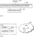
- Fig. 6 illustrates schematically a transmitting unit 600, which can be a base station such as an eNodeB in the case where the test is performed in a real network, or a test equipment such as a system simulator in the case where the test is performed in a lab.
- a processing unit 601 is configured to split the resources to be used for transmission into contiguous unities in the frequency domain according to a specific rule, and a transmitter 602 is configured to transmit to the UE 603 under test and to virtual users 604, also referred to as OCNG users.
- embodiments of the present invention provide the advantages that:
- OP.1 TDD OCNG TDD Pattern 1 (outer resource blocks allocation) for 5ms downlink-to-uplink switch-point periodicity
- OP.1 TDD OCNG TDD Pattern 1 ((outer resource blocks allocation) for special subframe configuration with 5ms downlink-to-uplink switch-point periodicity
Landscapes
- Engineering & Computer Science (AREA)
- Signal Processing (AREA)
- Computer Networks & Wireless Communication (AREA)
- Physics & Mathematics (AREA)
- Electromagnetism (AREA)
- Mobile Radio Communication Systems (AREA)
- Monitoring And Testing Of Transmission In General (AREA)
Description
- The present invention relates to UE performance tests in an OFDMA system.
- Different types of User Equipment, UE, performance requirements are specified in the standard. In order to ensure that UE meets these requirements, appropriate and relevant test cases are also specified. During the tests all the downlink radio resources are not typically needed for the user under test. In practical circumstances several users receive transmission simultaneously on different resources in a cell. To make the tests as realistic as possible these remaining channels or radio resources should be transmitted in a manner that mimics transmission to other users in a cell.
- The objective of UE performance verification (or the so-called UE performance tests) is to verify that UE fulfils the desired performance requirements in a given scenario, conditions and channel environment. By desired performance requirements it is meant those specified in the standard or requested by an operator or by any prospective customer. The performance requirements span a very vast area of UE requirements, such as
- UE RF receiver requirements e.g. receiver sensitivity
- UE RF transmitter requirements e.g. UE transmit power accuracy
- UE demodulation requirements e.g. achievable throughput
- Radio resource management requirements e.g. handover delay
- We can classify the UE verification into two categories:
- Verification in lab
- Verification in real network
- In the verification in lab the base station is emulated by test equipment, which is often termed as system simulator. Thus all downlink transmission is done by the test equipment to the test UE. During a test all common and other necessary UE specific control channels are transmitted by the test equipment. In addition a data channel, e.g. PDSCH in E-UTRAN, is also needed to send necessary data and configure the UE. Furthermore typically a single UE is tested at a time. In most typical test cases the entire available downlink resources are not used by the UE. However to make test realistic the remaining downlink resources should also be transmitted to one or multiple virtual users.
- In OFDMA system the transmission resources comprises of time-frequency resources called resource blocks, which are sent with some transmit power level, see section relating to E-UTRAN Downlink Transmission. This type of resource allocation to generate load in OFDMA will be referred to as OFDM channel noise generator (OCNG) in the following. Thus OCNG is sent to a plurality of virtual users for loading the cell.
- These types of tests are demanded by the operators and are performed in a real network. The test may comprise of single or multiple UEs. Prior to the network roll out or in an early phase of deployment the traffic load is typically very low. In classical tests the cell load is generated by increasing transmission power on one or more common channels. However operators are now increasingly demanding the network vendors to generate cell load in realistic fashion for performing tests. This means resources, which are not allocated to the test users should be allocated to the virtual users emulating load in the cell. Thus either all or large part of available resources i.e. channels, transmit power etc is used in the tests. This requires base station to implement the ability to transmit remaining resources in order to generate load. Thus for OFDMA (i.e. in E-UTRAN) OCNG is also deemed to be implemented in an actual base station.
- In WCDMA orthogonal channel noise simulator (OCNS) is used to load cells in the test. The OCNS is implemented in both test equipment and also possibly in the base station. In the former case it is standardized in TS 25.101 and TS 25.133 for each type of test or same for similar tests. The OCNS comprises of channelization code and relative power. In a CDMA system the position of channelization code in a code tree is sensitive to intra-cell interference. Therefore more careful selection of codes for OCNS and their power levels is needed. An example of OCNS from TS 25.101 for UE demodulation tests is quoted below:
Table 1: DPCH Channelization Code and relative level settings for OCNS signal Channelization Code at SF=128 Relative Level setting (dB) (Note 1) DPCH Data (see NOTE 3) 2 -1 The DPCH data for each channelization code shall be uncorrelated with each other and with any wanted signal over the period of any measurement. For OCNS with transmit diversity the DPCH data sent to each antenna shall be either STTD encoded or generated from uncorrelated sources. 11 -3 17 -3 23 -5 31 -2 38 -4 47 -8 55 -7 62 -4 69 -6 78 -5 85 -9 94 -10 125 -8 113 -6 119 0 NOTE 1: The relative level setting specified in dB refers only to the relationship between the OCNS channels. The level of the OCNS channels relative to the lor of the complete signal is a function of the power of the other channels in the signal with the intention that the power of the group of OCNS channels is used to make the total signal add up to 1. NOTE 2: The DPCH Channelization Codes and relative level settings are chosen to simulate a signal with realistic Peak to Average Ratio. NOTE 3: For MBSFN, the group of OCNS channels represent orthogonal S-CCPCH channels instead of DPCH. Transmit diversity is not applicable to MBSFN which excludes STTD. - In E-UTRAN Orthogonal Frequency Division Multiplexing (OFDM) technology is used in the downlink, whereas DFT based pre-coded OFDM is used in uplink. In E-UTRAN the cell transmission bandwidth is divided into several time-frequency resources. Most of these resources comprise of resource blocks, which comprises of 0.5 ms (time slot) in time domain and 12 sub-carriers each of 15 kHz in frequency domain. However some of the resources used for common channels e.g. SCH channel (primary and synchronization sequences) or reference symbols are transmitted over one or more OFDM symbol in time domain in each sub-frame. Some other control signals such as PCFICH, PHICH and PDCCH are also sent in specific OFDMA symbol in each sub-frame. The resource blocks are used for transmitted user data or some control signaling e.g. paging, system information etc.
- Furthermore E-UTRAN is a pure packet data designed cellular system, in which transmissions of user data in uplink and downlink always take place via shared channels. As similar to HSPA in UTRAN, the UE monitors physical downlink control channels (PDCCH) in order to access UE dedicated user data on the physical downlink shared channel (PDSCH) and the network assigns uplink scheduling grants to the UE on demand basis for uplink transmission via the physical uplink control channel (PUCCH) and the physical uplink shared channel (PUSCH). Error detection is provided on transport blocks and control payloads through Cyclic Redundancy Check (CRC) on PDSCH and PUSCH, and HARQ operations ensure efficient retransmissions.
- In E-UTRAN, no downlink transmit power control (TPC) has been specified and uplink TPC commands are embedded in the control payload mapped to PDCCH, which are sent occasionally or frequently by the E-UTRAN base station (eNodeB).
- The physical layer signals and channels in E-UTRAN downlink are:
- Physical layer signals, i.e. reference signal (pilots) and synchronization signals;
- Physical broadcast channel (PBCH);
- PDCCH and PDSCH;
- Physical control format indicator channel (PCFICH); and
- Physical HARQ indicator channel (PHICH)
- Following observations can be done:
- Physical layer signals and PBCH are transmitted periodically;
- Error detection via CRC of transport blocks mapped to PBCH and PDSCH, and of control data mapped to PDCCH;
- Some uplink transmissions shall result in downlink responses through the physical channels PDCCH and PHICH;
- The cell load is generated by OCNS in WCDMA, UTRAN TDD or other CDMA systems. The same concept is not needed in E-UTRAN since radio interface is based on OFDMA technology, which is less sensitive to intra-cell interference. But there is still some leakage across the sub-carriers contributing to intra-cell interference due to transmitter and receiver imperfections. However inter-cell interference is not orthogonal and therefore it can still be considerable in OFDMA like in CDMA. Currently no rules on how to generate cell load for performing UE performance test are available for OFDMA systems.
- The document
US 6,456,652 B1 discloses a method for optimizing forward link coverage in a spread spectrum communication system, e.g., CDMA system. Spread spectrum test communication signals are transmitted from a base station at a known power level, using an antenna having a known beam direction. Orthogonal channel noise is simulated in order to model noise generated by wireless communication traffic existing in an operational communication system of many subscribers. A mobile station receives the test communication signals in a specific region of a cell, and measures signal quality parameters, e.g., RSSI, Ec/Io and a forward frame error rate (FFER), from the received signals and simulated noise. The measured signal quality parameters are compared to respective criteria. Each region is designating as being satisfactorily covered by the base station if the measured signal quality parameters substantially satisfy the criteria. Otherwise, base station equipment is adjusted to modify the transmission of the test communication signals, and the process is repeated. - The document
EP 1 906 569 A1 discloses that a wireless communication mobile station device is provided by which a throughput can be improved in multicarrier communication. In the device, a group control section controls a subcarrier group, of which CQI is to be reported, among a plurality of subcarrier groups to periodically change, by following pattern information. - For instance, the group control section changes the subcarrier group whose CQI is to be reported, by frame or TTI (Transmission Time Interval). Furthermore, the group control section specifies the subcarrier group whose CQI is to be reported, to an SINR detecting section and a CQI generating section.
- Thus, the objective of this invention is to define rules for loading the cell or test equipment based on OFDMA technology in the downlink for performing UE tests in realistic manner and according to well defined principles.
- The invention is carried out according to independent claims 1 and 12.
- A first aspect of the present invention relates to a method for performing UE performance test to verify that one or more UE under test fulfils certain performance requirements in an OFDMA system, in which test all or part of available downlink radio resources in a cell are used for transmission, comprising the step of splitting said resources used for transmission into contiguous unities in the frequency domain such that one or more of said unities consists of resources allocated to one or more UE under test; and at least one of said unities consists of resources allocated to virtual UEs.
- Since the UE under test only decodes UE specific channels, and not the channels used for the virtual users, the splitting of the transmitted resources means that the decoding is made less complex. Thus, the method according to this aspect of the invention, involving separating the resources allocated for the UE under test and for the OCNG users respectively into separate unities in the frequency domain, provides consistency to the test performance by applying the specified rule that implies a low complexity and constrain on the UE or UEs performing the test.
- Here, the term "contiguous" has the meaning of a consecutive, i.e continuous, arrangement within each unity.
- In a specific embodiment of the invention, the resources are split such that one or more contiguous unities of resources in the center of an available cell bandwidth are allocated to the one or more UE under test, and one or more contiguous unities of resources at the edges of said cell bandwidth are allocated to virtual UEs.
- In another specific embodiment, the resources are split such that one or more contiguous unities of resources at the edges of said cell bandwidth are allocated to the one or more UE under test, and one or more contiguous unities of resources in the center of an available cell bandwidth are allocated to virtual UEs.
- A second aspect of the invention relates to an arrangement in a node capable of performing UE performance test to verify that a UE fulfils certain performance requirements in an OFDMA system, in which all or part of available downlink radio resources are used for transmission, comprising a processing unit capable of executing an algorithm for splitting of said transmitted resources into contiguous unities in the frequency domain, such that one or more of said unities consists of resources allocated to the one or more UE under test, and at least one of said unities consists of resources allocated to virtual UEs.
- Rules governing OCNG users to load cells could be specified in the standard for all tests and should be implemented in the test equipment. They may also be implemented in actual base stations for verifying operator specific or standardized tests in real network.
- Thus, the node according to said second aspect of the invention may e.g. be a test equipment such as a system simulator or a radio base station capable of operating in an OFDM system, such as an eNodeB (Evolved NodeB).
- Other objects, advantages and novel features of the invention will become apparent from the following detailed description of the invention when considered in conjunction with the accompanying drawings and claims.
- The foregoing and other objects, features and advantages of the invention will be apparent from the following detailed description of preferred embodiments as illustrated in the drawings.
-
Figure 1 illustrates OCNG allocation at edges of cell transmission bandwidth; -
Figure 2 illustrates OCNG allocation in the center of cell transmission bandwidth; -
Figure 3 illustrates a method according to a first embodiment of the invention; -
Figure 4 illustrates a method according to a second embodiment of the invention; -
Figure 5 illustrates a method according to a third embodiment of the invention; -
Figure 6 illustrates a node capable of carrying out embodiments of the invention. - The present invention can be exemplified in the following non-limiting description of embodiments of the invention.
- Typically only a single UE is tested at a time in a lab to verify that the UE under test meets the performance requirements. When test is performed in real network there can be one or multiple UE but in any case the entire cell resources are rarely used. Thus both in a lab or real network tests, the unused resources are transmitted to non existing virtual UEs to load the cell and to thereby mimic a realistic scenario seen in an actual network. The objective of this invention is to define rules, which can be used to transmit both test UE(s) and virtual UEs when verifying UE performance requirements in an OFDMA system. In order words, rules should define the split of OFDMA cell transmission resources between the test user(s) and the OCNG users. According to embodiments of the invention, resources allocated to the UE or UEs under test and the virtual users are split into contiguous unities. The UE (or UEs) under test does not decode OCNG channels, but only has to decode UE specific channels such as PDSCH and other UE specific channels, for example paging mapped on PDSCH. The objective of OCNG, i.e. virtual users, is only to load the cell in order to create realistic test environment, and not to add complexity to the decoding of UE specific channels e.g PDSCH. Such unnecessary complexity would put additional constraint on the UE that is not relevant for the test performance itself. For the test performance, it is desirable to isolate the test environment from influence that is not relevant for the test. Unnecessary complexity could cause such problems for the UE under test that the purpose of the test being lost, and thus the test would be of no use. Furthermore, randomly generated or distributed arrangement of resources allocated to the UE under test could also lead to inconsistent test results.
-
Fig. 3 illustrates a method according to an embodiment of the invention, performed by a transmitting unit for example a base station or a system simulator. The test performance is started instep 301. Instep 302, the resources to be transmitted in the test are split in the frequency domain such that certain contiguous unit or units is/are allocated to the UE or UEs under test, and certain other contiguous unit or units is/are allocated to virtual users, also referred to as OCNG users. The transmitting unit thereafter transmits according to said split,step 303. - The embodiments described in the following apply to verification tests in lab as well as those done in a real network.
- According to an embodiment of the invention, all the available cell resources (i.e. in test equipment that mimics base station or an actual base station in case of real network test) are divided into three main groups: X, Y and Z. They are allocated as follows:
- Group X resources are allocated to common channels, whose position in time and frequency domains are well specified. Examples of common channels are: SCH, PBCH, reference symbols, PCFICH, PDCCH etc
- Group Y resources are allocated to the test user(s).
- Group Z resources are indeed OCNG and are allocated to virtual users, also called OCNG users.
- Since common channel allocation is already well defined in the standard, the embodiments described herein will focus on how cell resources are split between group Y, i.e. resources allocated to the test users, and group Z, i.e. resources allocated to OCNG users.
- In radio resource management (RRM) tests such as tests related to handover or cell reselection, typically two or more cells are used, where for instance one of the cells is a target cell. Group Y, i.e. the resources allocated to the test users, is in that case used for configuring UE via the initial or a serving cell. This means that as a special case the Y group can be zero in one or more of the cells involved in some RRM tests.
- According to one specific embodiment, the resources are allocated such that OCNG users are allocated resource blocks at the edges of the cell bandwidth, while the test user(s) is/are allocated resource blocks (i.e. group Y) in the middle of the cell transmission bandwidth in contiguous manner. Typically, the common channels such as SCH, PBCH, reference symbols, PCFICH, PDCCH are also located in the center of the bandwidth. Thus, the resource blocks allocated to the virtual users i.e. group Z, are arranged in contiguous unities in frequency domain at the edges of the cell bandwidth and scheduled and transmitted to OCNG users, i.e. virtual users. This arrangement is shown in
Fig. 1 . A method according to this embodiment, performed by a transmitting unit, for example a base station or a system simulator, is illustrated inFig. 4 . The test performance is started instep 401. Instep 402, the resources to be transmitted in the test are split in the frequency domain such that a contiguous unit of resource blocks in the center of the cell bandwidth is allocated to the UE or UEs under test, while a contiguous unit of resource blocks at each edge of the cell bandwidth is allocated to virtual users, also referred to as OCNG users. The transmitting unit thereafter transmits according to said split of resources,step 403. - According to an alternative specific embodiment, the resources are allocated such that OCNG users are allocated resource blocks in the middle of the cell bandwidth, while the test user(s) is/are allocated resource blocks (i.e. group Y) at one or both edges of the cell transmission bandwidth in contiguous manner. Thus, the resource blocks allocated to virtual users, i.e. group Z, are arranged in contiguous unities in frequency domain in the center of the cell bandwidth and are transmitted to OCNG users, i.e. virtual users when carrying out the test. This arrangement where OCNG is transmitted in center of the bandwidth is shown in
figure 2 . A method according to this embodiment, performed by a transmitting unit for example a base station or a system simulator, is illustrated inFig. 5 . The test performance is started instep 501. Instep 502, the resources to be transmitted in the test are split in the frequency domain such that a contiguous unit of resource blocks at each edge of the cell bandwidth is allocated to the UE or UEs under test, while a contiguous unit of resource blocks in the center of the cell bandwidth is allocated to virtual users, also referred to as OCNG users. The transmitting unit thereafter transmits according to said split of resources,step 503. - The allocation of resource blocks between the test users and the virtual users may be fixed, for example such that 50% of all available resource blocks are allocated to the test user(s). For instance in case of 10 MHz bandwidth there are in total 50 RB, out of which 25 RB can be allocated to test user(s). In lab test there is typically only one user and therefore all 25 RB would be assigned to this user. In case of two or more test users the resource blocks can be equally split between the users or split with different proportion depending upon the type of information to be sent to these users. Dummy data may be transmitted in case the resources allocated to the UE under test are redundant for the test user. This will keep the number of resource blocks constant in group Y and make the test case more stable. The dummy data may comprise of some random sequences, which are stored in the test equipment and periodically sent to the virtual OCNG users.
- In a specific arrangement there will be one resource block assigned per each individual OCNG user i.e. there will be as many OCNG users as the number of resource blocks in group Z. In the example above (10 MHz bandwidth) there should according to this rule be 25 OCNG users (i.e. 1 RB per OCNG user). A low bit rate data (e.g. voice service) can be transmitted to OCNG users. In another arrangement there can be fewer OCNG users than the number of resource blocks in group Z, whereby more than one resource block are allocated to each OCNG user. For instance in the above example, if we have five OCNG users, then five resource blocks are allocated to each OCNG user.
- It should be noted that in specific embodiments, power can be different on different resource blocks due to power boosting on some channels to improve coverage. This may depend upon the specific test case.
- Typically, QPSK could be used for the modulation of the OCNG transmission. However, depending upon the test also higher order modulation could be used. In a specific embodiment, the modulation used for resources allocated to the
virtual users 604 is the same as used for the one ormore UE 603 under test. - In case MIMO (multiple transmit and receive antennas, transmit diversity, cyclic delay diversity, etc) is used, the OCNG can be transmitted from uncorrelated sources, i.e. uncorrelated transmit antennas. Alternatively depending upon the type of test the OCNG can use the same MIMO transmission method and the same correlation model which is used for data transmission to the test user.
-
Fig. 6 illustrates schematically a transmittingunit 600, which can be a base station such as an eNodeB in the case where the test is performed in a real network, or a test equipment such as a system simulator in the case where the test is performed in a lab. For the sake of clarity, only units that are relevant for this invention are illustrated in this figure. Aprocessing unit 601 is configured to split the resources to be used for transmission into contiguous unities in the frequency domain according to a specific rule, and atransmitter 602 is configured to transmit to theUE 603 under test and tovirtual users 604, also referred to as OCNG users. - Thus, embodiments of the present invention provide the advantages that:
- The load generation in a test is simplified and testing complexity is reduced.
- The load generation in a base station such as an e-NodeB is simplified based on the rules above for load tests in real networks.
- Performance requirements can be properly verified since consistent rules for generating load in the cell are used in the tests since well defined load generation will allow easy distinction between the performance of good and bad UEs.
- An implementation of the invention is exemplified in the following, which constitutes an example of how embodiments of the invention could be included in TS 36.133 version 8.4.0:
-


-

-


-
- OFDM:
- Orthogonal Frequency Division Multiplexing
- OFDMA:
- Orthogonal Frequency Division Multiple Access
- WCDMA:
- Wide band code division multiple access
- UE:
- User Equipment
- OCNS:
- Orthogonal channel noise simulator
- OCNG:
- OFMA channel noise generator
- SCH:
- Synchronisation Channel
- PBCH:
- Physical Broadcast Channel
- PCFICH:
- Physical Control Format Indicator Channel
- PDCCH:
- Physical Downlink Control Channel
- RB:
- Resource Block
- QPSK:
- Quadrature Phase Shift Keying
Claims (22)
- A method for performing UE performance test to verify that one or more UE under test fulfils certain performance requirements in an OFDMA system, in which test all or part of available downlink radio resources in a cell are used for transmission, comprising the step of splitting (302, 402, 502) said resources used for transmission into contiguous unities (101, 102, 103, 201, 202, 203) in the frequency domain such that one or more of said unities consists of resources allocated to one or more UE under test (603); and at least one of said unities consists of resources allocated to virtual UEs (604).
- The method according to claim 1, comprising the step of splitting the resources such that one or more contiguous unities (102) of resources in the center of an available cell bandwidth are allocated to the one or more UE (603) under test, and one or more contiguous unities (101) of resources at the edges of said cell bandwidth are allocated to virtual UEs (604).
- The method according to claim 1, comprising the step of splitting the resources such that one or more contiguous unities (202) of resources at the edges of said cell bandwidth are allocated to the one or more UE (603) under test, and one or more contiguous unities (201) of resources in the center of an available cell bandwidth are allocated to virtual UEs (604).
- The method according to any of claims 1 - 3, wherein out of the contiguous unities (101, 201) of resources available for the virtual users, one resource block is allocated to each of the said virtual UEs (604).
- The method according to any of claims 1 - 4, wherein QPSK modulation is used for resources allocated to the virtual UEs (604).
- The method according to any of claims 1 - 5, wherein when MIMO is used, the transmission to the virtual UEs (604) is carried out via uncorrelated transmit antennas.
- The method according to any of claims 1 - 5, wherein when MIMO is used, the transmission to the virtual UEs (604) is carried out via the same MIMO transmission method and using same correlation model as used for the one or more UE (603) under test.
- The method according to any of claims 1 - 7, wherein the allocation of resources to the one or more UE (603) under test and the virtual UEs (604) respectively is fixed.
- The method according to any of claims 1 - 8, comprising the step of transmitting resources allocated for the one or more UE (603) under test on the PDSCH.
- The method according to any of claims 1 - 9, wherein said method is carried out by a test equipment (600) such as a system simulator.
- The method according to any of claims 1 - 9, wherein said method is carried out by a base station (600) capable of operating in an OFDM system.
- An arrangement for a node (600) capable of performing UE performance test to verify that a UE fulfils certain performance requirements in an OFDMA system, in which test all or part of available downlink radio resources are used for transmission, comprising a processing unit (601) capable of executing an algorithm for splitting of said transmitted resources into contiguous unities (101, 102, 103, 201, 202, 203) in the frequency domain, such that one or more of said unities consists of resources allocated to the one or more UE (603) under test, and at least one of said unities consists of resources allocated to virtual UEs (604).
- The arrangement according to claim 14, wherein said processing unit is configured to split the resources such that one or more contiguous unities (102) of resources in the center of an available cell bandwidth are allocated to the one or more UE (603) under test, and one or more contiguous unities (101) of resources at the edges of said cell bandwidth are allocated to virtual UEs (604).
- The arrangement according to claim 12, wherein said processing unit is configured to split the resources such that one or more contiguous unities (202) of resources at the edges of said cell bandwidth are allocated to the one or more UE (603) under test, and one or more contiguous unities (201) of resources in the center of an available cell bandwidth are allocated to virtual UEs (604).
- The arrangement according to any of claims 12-14, wherein said processing unit (601) is configured to allocate, out of the contiguous unities (101, 201) of resources available for the virtual users, one resource block to each of the said virtual UEs (604).
- The arrangement according to any of claims 12-15, wherein said processing unit (601) is configured to use QPSK modulation for resources allocated to the virtual UEs (604).
- The arrangement according to any of claims 12-16, wherein a transmitter 602 is configured to transmit to the virtual UEs (604) via uncorrelated transmit antennas when MIMO is used.
- The arrangement according to any of claims 12-16, wherein a transmitter 602 is configured to transmit to the virtual UEs (604) via the same MIMO transmission method and using same correlation model as used for the one or more UE (603) under test when MIMO is used.
- The arrangement according to any of claims 12-18, wherein said processing unit (601) is configured to allocate resources to the one or more UE (603) under test and the virtual UEs (604) in a fixed manner.
- The arrangement according to any of claims 12-19, comprising a transmitter (602) configured to transmit resources allocated for the one or more UE (603) under test on the PDSCH.
- The arrangement according to any of claims 12-20, wherein said node (600) is a test equipment such as a system simulator.
- The arrangement according to any of claims 12-20, wherein said node (600) is a base station capable of operating in an OFDM system.
Applications Claiming Priority (3)
| Application Number | Priority Date | Filing Date | Title |
|---|---|---|---|
| US6129008P | 2008-06-13 | 2008-06-13 | |
| EP08874637.5A EP2283673B1 (en) | 2008-06-13 | 2008-12-08 | Method and apparatus for a performance test in an ofdma system |
| PCT/SE2008/051421 WO2009151361A1 (en) | 2008-06-13 | 2008-12-08 | Method and apparatus for a performance test in an ofdma system |
Related Parent Applications (1)
| Application Number | Title | Priority Date | Filing Date |
|---|---|---|---|
| EP08874637.5A Division EP2283673B1 (en) | 2008-06-13 | 2008-12-08 | Method and apparatus for a performance test in an ofdma system |
Publications (2)
| Publication Number | Publication Date |
|---|---|
| EP3200500A1 EP3200500A1 (en) | 2017-08-02 |
| EP3200500B1 true EP3200500B1 (en) | 2020-07-22 |
Family
ID=40793111
Family Applications (2)
| Application Number | Title | Priority Date | Filing Date |
|---|---|---|---|
| EP17161346.6A Active EP3200500B1 (en) | 2008-06-13 | 2008-12-08 | Method and apparatus for a user equipment performance test in an ofdma system |
| EP08874637.5A Active EP2283673B1 (en) | 2008-06-13 | 2008-12-08 | Method and apparatus for a performance test in an ofdma system |
Family Applications After (1)
| Application Number | Title | Priority Date | Filing Date |
|---|---|---|---|
| EP08874637.5A Active EP2283673B1 (en) | 2008-06-13 | 2008-12-08 | Method and apparatus for a performance test in an ofdma system |
Country Status (12)
| Country | Link |
|---|---|
| US (1) | US8411553B2 (en) |
| EP (2) | EP3200500B1 (en) |
| JP (1) | JP4938909B2 (en) |
| CN (2) | CN103957555B (en) |
| CA (1) | CA2727863C (en) |
| CL (1) | CL2009001413A1 (en) |
| ES (1) | ES2628975T3 (en) |
| HU (1) | HUE033235T2 (en) |
| MX (1) | MX2010011759A (en) |
| MY (1) | MY152088A (en) |
| PL (1) | PL2283673T3 (en) |
| WO (1) | WO2009151361A1 (en) |
Families Citing this family (19)
| Publication number | Priority date | Publication date | Assignee | Title |
|---|---|---|---|---|
| EP3200500B1 (en) * | 2008-06-13 | 2020-07-22 | Telefonaktiebolaget LM Ericsson (publ) | Method and apparatus for a user equipment performance test in an ofdma system |
| US8780728B1 (en) * | 2008-12-22 | 2014-07-15 | Blackberry Limited | Test loading in OFDMA wireless networks |
| US9450727B2 (en) * | 2009-02-03 | 2016-09-20 | Google Technology Holdings LLC | Physical layer acknowledgement signaling resource allocation in wireless communication systems |
| US8660072B2 (en) * | 2010-01-18 | 2014-02-25 | Telefonaktiebolaget L M Ericsson (Publ) | Methods and apparatus for improved reference signal correlation characteristics |
| CN102244537B (en) * | 2010-05-13 | 2014-07-16 | 中兴通讯股份有限公司 | Method for loading uplink analog data of terminal and terminal |
| CN102111470B (en) * | 2011-03-30 | 2013-07-31 | 中国联合网络通信集团有限公司 | Method for detecting wireless transceiving performance of mobile communication terminal |
| US9241280B2 (en) | 2011-04-29 | 2016-01-19 | Telefonaktiebolaget L M Ericsson (Publ) | Methods and arrangements for testing a transmission parameter value in a wireless communication system |
| EP2523494B1 (en) * | 2011-05-11 | 2014-01-29 | Prisma Engineering S.r.l. | Mobile terminal simulator for a wireless telecommunications network and method to simulate a mobile terminal |
| US9244807B2 (en) * | 2011-06-24 | 2016-01-26 | International Business Machines Corporation | Quasi disk drive for testing disk interface performance |
| CN102355689B (en) * | 2011-09-27 | 2013-11-20 | 大唐移动通信设备有限公司 | Terminal interference test realizing method and device |
| US8983395B2 (en) * | 2011-12-12 | 2015-03-17 | Apple Inc. | Methods and apparatus for testing radio-frequency power amplifier performance |
| CN103731867B (en) * | 2012-10-16 | 2017-06-20 | 中国移动通信集团公司 | The system and method for realizing test network and the load equity of actual communication network |
| JP5771249B2 (en) * | 2013-09-09 | 2015-08-26 | アンリツ株式会社 | Mobile communication terminal test apparatus and mobile communication terminal test method |
| US20150111589A1 (en) * | 2013-10-18 | 2015-04-23 | Qualcomm Incorporated | Method and apparatus for optimizing coverage area of a small cell |
| CN104852879B (en) * | 2015-04-07 | 2017-11-03 | 湖南大学 | A kind of dynamic suppressing method of power line impulsive noise and system |
| CN105142173B (en) * | 2015-08-27 | 2018-10-12 | 华为技术有限公司 | A kind of signal output apparatus, board and method |
| WO2019081025A1 (en) | 2017-10-26 | 2019-05-02 | Telefonaktiebolaget Lm Ericsson (Publ) | Method and nodes for testing a node |
| WO2020005133A1 (en) * | 2018-06-25 | 2020-01-02 | Telefonaktiebolaget Lm Ericsson (Publ) | Method of generating ss-ocng in a radio node |
| CN119136237B (en) * | 2024-11-04 | 2025-01-24 | 四川创智联恒科技有限公司 | Communication simulation method, device, program product, storage medium and electronic device |
Family Cites Families (24)
| Publication number | Priority date | Publication date | Assignee | Title |
|---|---|---|---|---|
| KR100278019B1 (en) * | 1998-03-28 | 2001-01-15 | 윤종용 | A method for optimizing forward link coverage in cdma network |
| US6434364B1 (en) * | 1998-12-24 | 2002-08-13 | Telefonaktiebolaget Lm Ericsson (Publ) | Wireless communication system that supports mobile test software agents |
| JP3908548B2 (en) * | 2002-01-31 | 2007-04-25 | Necエンジニアリング株式会社 | User data load test equipment |
| KR101000388B1 (en) * | 2003-05-15 | 2010-12-13 | 엘지전자 주식회사 | Mobile communication system and method for processing signals in the mobile communication system |
| JP4083693B2 (en) * | 2004-02-26 | 2008-04-30 | アンリツ株式会社 | Pseudo base station equipment |
| US7046617B2 (en) * | 2004-03-22 | 2006-05-16 | Motorola, Inc. | Method and apparatus for an enhanced OFDM system |
| CN100508636C (en) * | 2004-06-28 | 2009-07-01 | 华为技术有限公司 | A kind of RNC air interface test equipment and test method |
| US7317915B2 (en) * | 2004-07-12 | 2008-01-08 | Telefonaktiebolaget Lm Ericsson (Publ) | Method and apparatus for testing a radio network |
| US7573851B2 (en) * | 2004-12-07 | 2009-08-11 | Adaptix, Inc. | Method and system for switching antenna and channel assignments in broadband wireless networks |
| US7400887B2 (en) * | 2005-03-17 | 2008-07-15 | Lucent Technologies Inc. | Method for estimating the downlink capacity in a spread spectrum wireless communications system |
| JP4768739B2 (en) * | 2005-08-19 | 2011-09-07 | パナソニック株式会社 | RADIO COMMUNICATION MOBILE STATION DEVICE, RADIO COMMUNICATION BASE STATION DEVICE, AND CQI REPORTING METHOD |
| US20070230356A1 (en) * | 2006-04-04 | 2007-10-04 | Kalantri Sacchindrakumar G | Method and apparatus for enabling FLO device certification |
| US7782900B2 (en) * | 2006-05-01 | 2010-08-24 | Alcatel-Lucent Usa Inc. | Method for increasing spectrum efficiency in an OFDM based multi-bandwidth wireless system |
| JP2007325111A (en) * | 2006-06-02 | 2007-12-13 | Nec Commun Syst Ltd | Base station test apparatus, base station test system, and base station test method of base station test system |
| US7620370B2 (en) * | 2006-07-13 | 2009-11-17 | Designart Networks Ltd | Mobile broadband wireless access point network with wireless backhaul |
| US8271043B2 (en) * | 2006-08-21 | 2012-09-18 | Qualcomm Incorporated | Approach to a unified SU-MIMO/MU-MIMO operation |
| JP5237287B2 (en) * | 2006-10-02 | 2013-07-17 | エルジー エレクトロニクス インコーポレイティド | Downlink control signal transmission method |
| KR100970185B1 (en) * | 2006-10-30 | 2010-07-14 | 삼성전자주식회사 | Resource allocation method and device in multi-channel system |
| US8155638B2 (en) * | 2006-12-28 | 2012-04-10 | Alcatel Lucent | Orthogonal code noise simulator for high speed downlink packet access |
| KR100922476B1 (en) * | 2007-04-23 | 2009-10-21 | 에스케이 텔레콤주식회사 | Method and device for network-directed selection of Crm and mobile terminal in multiple wireless networks |
| US20080310359A1 (en) * | 2007-06-15 | 2008-12-18 | Mcbeath Sean Michael | Method and Apparatus for Sharing Resources in a Wireless System |
| ES2329630T3 (en) * | 2007-07-23 | 2009-11-27 | Alcatel Lucent | A SIGNALING METHOD. |
| US9288021B2 (en) * | 2008-05-02 | 2016-03-15 | Qualcomm Incorporated | Method and apparatus for uplink ACK/NACK resource allocation |
| EP3200500B1 (en) * | 2008-06-13 | 2020-07-22 | Telefonaktiebolaget LM Ericsson (publ) | Method and apparatus for a user equipment performance test in an ofdma system |
-
2008
- 2008-12-08 EP EP17161346.6A patent/EP3200500B1/en active Active
- 2008-12-08 JP JP2011513449A patent/JP4938909B2/en active Active
- 2008-12-08 CA CA2727863A patent/CA2727863C/en active Active
- 2008-12-08 MY MYPI20105027 patent/MY152088A/en unknown
- 2008-12-08 MX MX2010011759A patent/MX2010011759A/en active IP Right Grant
- 2008-12-08 PL PL08874637T patent/PL2283673T3/en unknown
- 2008-12-08 HU HUE08874637A patent/HUE033235T2/en unknown
- 2008-12-08 CN CN201410194256.0A patent/CN103957555B/en active Active
- 2008-12-08 CN CN200880129913.6A patent/CN102067656B/en active Active
- 2008-12-08 ES ES08874637.5T patent/ES2628975T3/en active Active
- 2008-12-08 WO PCT/SE2008/051421 patent/WO2009151361A1/en active Application Filing
- 2008-12-08 EP EP08874637.5A patent/EP2283673B1/en active Active
-
2009
- 2009-05-27 US US12/472,430 patent/US8411553B2/en active Active
- 2009-06-12 CL CL2009001413A patent/CL2009001413A1/en unknown
Non-Patent Citations (1)
| Title |
|---|
| None * |
Also Published As
| Publication number | Publication date |
|---|---|
| EP2283673B1 (en) | 2017-03-22 |
| CL2009001413A1 (en) | 2010-08-13 |
| CN102067656A (en) | 2011-05-18 |
| US8411553B2 (en) | 2013-04-02 |
| JP4938909B2 (en) | 2012-05-23 |
| PL2283673T3 (en) | 2017-09-29 |
| US20090310492A1 (en) | 2009-12-17 |
| HUE033235T2 (en) | 2017-11-28 |
| ES2628975T3 (en) | 2017-08-04 |
| CN103957555B (en) | 2017-12-12 |
| CN103957555A (en) | 2014-07-30 |
| MY152088A (en) | 2014-08-15 |
| JP2011524143A (en) | 2011-08-25 |
| CN102067656B (en) | 2014-06-11 |
| MX2010011759A (en) | 2010-11-30 |
| EP3200500A1 (en) | 2017-08-02 |
| EP2283673A1 (en) | 2011-02-16 |
| CA2727863A1 (en) | 2009-12-17 |
| CA2727863C (en) | 2016-11-29 |
| WO2009151361A1 (en) | 2009-12-17 |
Similar Documents
| Publication | Publication Date | Title |
|---|---|---|
| EP3200500B1 (en) | Method and apparatus for a user equipment performance test in an ofdma system | |
| US11109385B2 (en) | Method and apparatus for measuring downlink interference in OFDM mobile communication system | |
| CN112166574B (en) | Method and apparatus for multiple PCell configuration for URLLC reliability | |
| RU2660935C2 (en) | Interference measurement method and apparatus for use in distributed antenna system | |
| CN108540255B (en) | Base station device, terminal device, and integrated circuit | |
| US20150098369A1 (en) | Reference signal design for special subframe configurations | |
| KR20190122876A (en) | Method and apparatus for indicating reference signal in wireless system | |
| EP3217711B1 (en) | Base station device, terminal device, and communication method | |
| EP2866492A1 (en) | Wireless communication system, wireless base station device, user terminal, and communication control method | |
| EP2642670A1 (en) | Communication method, device and system for a distributed antenna system | |
| EP3217712B1 (en) | Base station device, terminal device, and communication method | |
| CN102685038B (en) | A kind of method and system for demodulating the binding demodulation of pilot physical resource block | |
| US10721638B2 (en) | Method and apparatus for testing mobile terminals in an OFDM system | |
| US10219226B2 (en) | Base station apparatus, terminal apparatus, and communication method | |
| JP2016536839A (en) | Method, apparatus and system for operating based on subframe sets and for generating signaling | |
| İbişoğlu | Analysis and performance measurements of MIMO OFDM techniques for LTE | |
| CN118104199A (en) | Uplink waveform indicating method, device, medium and product | |
| HK1257834B (en) | Base station apparatus, terminal apparatus, and integrated circuit | |
| HK1257834A1 (en) | Base station apparatus, terminal apparatus, and integrated circuit |
Legal Events
| Date | Code | Title | Description |
|---|---|---|---|
| PUAI | Public reference made under article 153(3) epc to a published international application that has entered the european phase |
Free format text: ORIGINAL CODE: 0009012 |
|
| STAA | Information on the status of an ep patent application or granted ep patent |
Free format text: STATUS: THE APPLICATION HAS BEEN PUBLISHED |
|
| AC | Divisional application: reference to earlier application |
Ref document number: 2283673 Country of ref document: EP Kind code of ref document: P |
|
| AK | Designated contracting states |
Kind code of ref document: A1 Designated state(s): AT BE BG CH CY CZ DE DK EE ES FI FR GB GR HR HU IE IS IT LI LT LU LV MC MT NL NO PL PT RO SE SI SK TR |
|
| STAA | Information on the status of an ep patent application or granted ep patent |
Free format text: STATUS: REQUEST FOR EXAMINATION WAS MADE |
|
| 17P | Request for examination filed |
Effective date: 20180202 |
|
| RBV | Designated contracting states (corrected) |
Designated state(s): AT BE BG CH CY CZ DE DK EE ES FI FR GB GR HR HU IE IS IT LI LT LU LV MC MT NL NO PL PT RO SE SI SK TR |
|
| GRAP | Despatch of communication of intention to grant a patent |
Free format text: ORIGINAL CODE: EPIDOSNIGR1 |
|
| STAA | Information on the status of an ep patent application or granted ep patent |
Free format text: STATUS: GRANT OF PATENT IS INTENDED |
|
| INTG | Intention to grant announced |
Effective date: 20200420 |
|
| RIN1 | Information on inventor provided before grant (corrected) |
Inventor name: AXMON, JOAKIM Inventor name: MUELLER, WALTER Inventor name: KAZMI, MUHAMMAD Inventor name: BERGLJUNG, CHRISTIAN Inventor name: GHASEMZADEH, FARSHID |
|
| GRAS | Grant fee paid |
Free format text: ORIGINAL CODE: EPIDOSNIGR3 |
|
| GRAA | (expected) grant |
Free format text: ORIGINAL CODE: 0009210 |
|
| STAA | Information on the status of an ep patent application or granted ep patent |
Free format text: STATUS: THE PATENT HAS BEEN GRANTED |
|
| AC | Divisional application: reference to earlier application |
Ref document number: 2283673 Country of ref document: EP Kind code of ref document: P |
|
| AK | Designated contracting states |
Kind code of ref document: B1 Designated state(s): AT BE BG CH CY CZ DE DK EE ES FI FR GB GR HR HU IE IS IT LI LT LU LV MC MT NL NO PL PT RO SE SI SK TR |
|
| REG | Reference to a national code |
Ref country code: GB Ref legal event code: FG4D |
|
| REG | Reference to a national code |
Ref country code: CH Ref legal event code: EP |
|
| REG | Reference to a national code |
Ref country code: DE Ref legal event code: R096 Ref document number: 602008063043 Country of ref document: DE |
|
| REG | Reference to a national code |
Ref country code: AT Ref legal event code: REF Ref document number: 1294594 Country of ref document: AT Kind code of ref document: T Effective date: 20200815 |
|
| REG | Reference to a national code |
Ref country code: IE Ref legal event code: FG4D |
|
| REG | Reference to a national code |
Ref country code: LT Ref legal event code: MG4D |
|
| REG | Reference to a national code |
Ref country code: AT Ref legal event code: MK05 Ref document number: 1294594 Country of ref document: AT Kind code of ref document: T Effective date: 20200722 |
|
| PG25 | Lapsed in a contracting state [announced via postgrant information from national office to epo] |
Ref country code: PT Free format text: LAPSE BECAUSE OF FAILURE TO SUBMIT A TRANSLATION OF THE DESCRIPTION OR TO PAY THE FEE WITHIN THE PRESCRIBED TIME-LIMIT Effective date: 20201123 Ref country code: BG Free format text: LAPSE BECAUSE OF FAILURE TO SUBMIT A TRANSLATION OF THE DESCRIPTION OR TO PAY THE FEE WITHIN THE PRESCRIBED TIME-LIMIT Effective date: 20201022 Ref country code: AT Free format text: LAPSE BECAUSE OF FAILURE TO SUBMIT A TRANSLATION OF THE DESCRIPTION OR TO PAY THE FEE WITHIN THE PRESCRIBED TIME-LIMIT Effective date: 20200722 Ref country code: ES Free format text: LAPSE BECAUSE OF FAILURE TO SUBMIT A TRANSLATION OF THE DESCRIPTION OR TO PAY THE FEE WITHIN THE PRESCRIBED TIME-LIMIT Effective date: 20200722 Ref country code: NO Free format text: LAPSE BECAUSE OF FAILURE TO SUBMIT A TRANSLATION OF THE DESCRIPTION OR TO PAY THE FEE WITHIN THE PRESCRIBED TIME-LIMIT Effective date: 20201022 Ref country code: GR Free format text: LAPSE BECAUSE OF FAILURE TO SUBMIT A TRANSLATION OF THE DESCRIPTION OR TO PAY THE FEE WITHIN THE PRESCRIBED TIME-LIMIT Effective date: 20201023 Ref country code: SE Free format text: LAPSE BECAUSE OF FAILURE TO SUBMIT A TRANSLATION OF THE DESCRIPTION OR TO PAY THE FEE WITHIN THE PRESCRIBED TIME-LIMIT Effective date: 20200722 Ref country code: HR Free format text: LAPSE BECAUSE OF FAILURE TO SUBMIT A TRANSLATION OF THE DESCRIPTION OR TO PAY THE FEE WITHIN THE PRESCRIBED TIME-LIMIT Effective date: 20200722 Ref country code: LT Free format text: LAPSE BECAUSE OF FAILURE TO SUBMIT A TRANSLATION OF THE DESCRIPTION OR TO PAY THE FEE WITHIN THE PRESCRIBED TIME-LIMIT Effective date: 20200722 Ref country code: FI Free format text: LAPSE BECAUSE OF FAILURE TO SUBMIT A TRANSLATION OF THE DESCRIPTION OR TO PAY THE FEE WITHIN THE PRESCRIBED TIME-LIMIT Effective date: 20200722 |
|
| PG25 | Lapsed in a contracting state [announced via postgrant information from national office to epo] |
Ref country code: IS Free format text: LAPSE BECAUSE OF FAILURE TO SUBMIT A TRANSLATION OF THE DESCRIPTION OR TO PAY THE FEE WITHIN THE PRESCRIBED TIME-LIMIT Effective date: 20201122 Ref country code: LV Free format text: LAPSE BECAUSE OF FAILURE TO SUBMIT A TRANSLATION OF THE DESCRIPTION OR TO PAY THE FEE WITHIN THE PRESCRIBED TIME-LIMIT Effective date: 20200722 Ref country code: PL Free format text: LAPSE BECAUSE OF FAILURE TO SUBMIT A TRANSLATION OF THE DESCRIPTION OR TO PAY THE FEE WITHIN THE PRESCRIBED TIME-LIMIT Effective date: 20200722 |
|
| PG25 | Lapsed in a contracting state [announced via postgrant information from national office to epo] |
Ref country code: NL Free format text: LAPSE BECAUSE OF FAILURE TO SUBMIT A TRANSLATION OF THE DESCRIPTION OR TO PAY THE FEE WITHIN THE PRESCRIBED TIME-LIMIT Effective date: 20200722 |
|
| REG | Reference to a national code |
Ref country code: DE Ref legal event code: R097 Ref document number: 602008063043 Country of ref document: DE |
|
| PG25 | Lapsed in a contracting state [announced via postgrant information from national office to epo] |
Ref country code: RO Free format text: LAPSE BECAUSE OF FAILURE TO SUBMIT A TRANSLATION OF THE DESCRIPTION OR TO PAY THE FEE WITHIN THE PRESCRIBED TIME-LIMIT Effective date: 20200722 Ref country code: DK Free format text: LAPSE BECAUSE OF FAILURE TO SUBMIT A TRANSLATION OF THE DESCRIPTION OR TO PAY THE FEE WITHIN THE PRESCRIBED TIME-LIMIT Effective date: 20200722 Ref country code: CZ Free format text: LAPSE BECAUSE OF FAILURE TO SUBMIT A TRANSLATION OF THE DESCRIPTION OR TO PAY THE FEE WITHIN THE PRESCRIBED TIME-LIMIT Effective date: 20200722 Ref country code: IT Free format text: LAPSE BECAUSE OF FAILURE TO SUBMIT A TRANSLATION OF THE DESCRIPTION OR TO PAY THE FEE WITHIN THE PRESCRIBED TIME-LIMIT Effective date: 20200722 Ref country code: EE Free format text: LAPSE BECAUSE OF FAILURE TO SUBMIT A TRANSLATION OF THE DESCRIPTION OR TO PAY THE FEE WITHIN THE PRESCRIBED TIME-LIMIT Effective date: 20200722 |
|
| PLBE | No opposition filed within time limit |
Free format text: ORIGINAL CODE: 0009261 |
|
| STAA | Information on the status of an ep patent application or granted ep patent |
Free format text: STATUS: NO OPPOSITION FILED WITHIN TIME LIMIT |
|
| 26N | No opposition filed |
Effective date: 20210423 |
|
| PG25 | Lapsed in a contracting state [announced via postgrant information from national office to epo] |
Ref country code: SK Free format text: LAPSE BECAUSE OF FAILURE TO SUBMIT A TRANSLATION OF THE DESCRIPTION OR TO PAY THE FEE WITHIN THE PRESCRIBED TIME-LIMIT Effective date: 20200722 |
|
| REG | Reference to a national code |
Ref country code: CH Ref legal event code: PL |
|
| PG25 | Lapsed in a contracting state [announced via postgrant information from national office to epo] |
Ref country code: MC Free format text: LAPSE BECAUSE OF FAILURE TO SUBMIT A TRANSLATION OF THE DESCRIPTION OR TO PAY THE FEE WITHIN THE PRESCRIBED TIME-LIMIT Effective date: 20200722 Ref country code: SI Free format text: LAPSE BECAUSE OF FAILURE TO SUBMIT A TRANSLATION OF THE DESCRIPTION OR TO PAY THE FEE WITHIN THE PRESCRIBED TIME-LIMIT Effective date: 20200722 |
|
| REG | Reference to a national code |
Ref country code: BE Ref legal event code: MM Effective date: 20201231 |
|
| REG | Reference to a national code |
Ref country code: NL Ref legal event code: MP Effective date: 20200722 |
|
| PG25 | Lapsed in a contracting state [announced via postgrant information from national office to epo] |
Ref country code: IE Free format text: LAPSE BECAUSE OF NON-PAYMENT OF DUE FEES Effective date: 20201208 Ref country code: LU Free format text: LAPSE BECAUSE OF NON-PAYMENT OF DUE FEES Effective date: 20201208 |
|
| PG25 | Lapsed in a contracting state [announced via postgrant information from national office to epo] |
Ref country code: LI Free format text: LAPSE BECAUSE OF NON-PAYMENT OF DUE FEES Effective date: 20201231 Ref country code: CH Free format text: LAPSE BECAUSE OF NON-PAYMENT OF DUE FEES Effective date: 20201231 |
|
| PG25 | Lapsed in a contracting state [announced via postgrant information from national office to epo] |
Ref country code: TR Free format text: LAPSE BECAUSE OF FAILURE TO SUBMIT A TRANSLATION OF THE DESCRIPTION OR TO PAY THE FEE WITHIN THE PRESCRIBED TIME-LIMIT Effective date: 20200722 Ref country code: MT Free format text: LAPSE BECAUSE OF FAILURE TO SUBMIT A TRANSLATION OF THE DESCRIPTION OR TO PAY THE FEE WITHIN THE PRESCRIBED TIME-LIMIT Effective date: 20200722 Ref country code: CY Free format text: LAPSE BECAUSE OF FAILURE TO SUBMIT A TRANSLATION OF THE DESCRIPTION OR TO PAY THE FEE WITHIN THE PRESCRIBED TIME-LIMIT Effective date: 20200722 |
|
| PG25 | Lapsed in a contracting state [announced via postgrant information from national office to epo] |
Ref country code: BE Free format text: LAPSE BECAUSE OF NON-PAYMENT OF DUE FEES Effective date: 20201231 |
|
| PGFP | Annual fee paid to national office [announced via postgrant information from national office to epo] |
Ref country code: GB Payment date: 20241227 Year of fee payment: 17 |
|
| PGFP | Annual fee paid to national office [announced via postgrant information from national office to epo] |
Ref country code: FR Payment date: 20241226 Year of fee payment: 17 |
|
| PGFP | Annual fee paid to national office [announced via postgrant information from national office to epo] |
Ref country code: DE Payment date: 20241227 Year of fee payment: 17 |