EP3200455B1 - Method and device for compression and decompression of binary data - Google Patents
Method and device for compression and decompression of binary data Download PDFInfo
- Publication number
- EP3200455B1 EP3200455B1 EP16153212.2A EP16153212A EP3200455B1 EP 3200455 B1 EP3200455 B1 EP 3200455B1 EP 16153212 A EP16153212 A EP 16153212A EP 3200455 B1 EP3200455 B1 EP 3200455B1
- Authority
- EP
- European Patent Office
- Prior art keywords
- binary data
- values
- value
- bits
- input binary
- Prior art date
- Legal status (The legal status is an assumption and is not a legal conclusion. Google has not performed a legal analysis and makes no representation as to the accuracy of the status listed.)
- Active
Links
- 238000000034 method Methods 0.000 title claims description 103
- 238000007906 compression Methods 0.000 title claims description 25
- 230000006835 compression Effects 0.000 title claims description 25
- 230000006837 decompression Effects 0.000 title claims description 10
- 238000013139 quantization Methods 0.000 claims description 64
- 230000000875 corresponding effect Effects 0.000 description 18
- 230000002596 correlated effect Effects 0.000 description 4
- 230000008901 benefit Effects 0.000 description 3
- 230000008859 change Effects 0.000 description 2
- 230000008569 process Effects 0.000 description 2
- 239000013598 vector Substances 0.000 description 2
- 238000007792 addition Methods 0.000 description 1
- 230000005540 biological transmission Effects 0.000 description 1
- 238000004891 communication Methods 0.000 description 1
- 230000021615 conjugation Effects 0.000 description 1
- 238000013144 data compression Methods 0.000 description 1
- 230000001419 dependent effect Effects 0.000 description 1
- 230000006872 improvement Effects 0.000 description 1
- 238000012804 iterative process Methods 0.000 description 1
- 230000001681 protective effect Effects 0.000 description 1
- 230000009467 reduction Effects 0.000 description 1
Images


Classifications
-
- H—ELECTRICITY
- H04—ELECTRIC COMMUNICATION TECHNIQUE
- H04N—PICTORIAL COMMUNICATION, e.g. TELEVISION
- H04N19/00—Methods or arrangements for coding, decoding, compressing or decompressing digital video signals
- H04N19/10—Methods or arrangements for coding, decoding, compressing or decompressing digital video signals using adaptive coding
- H04N19/102—Methods or arrangements for coding, decoding, compressing or decompressing digital video signals using adaptive coding characterised by the element, parameter or selection affected or controlled by the adaptive coding
- H04N19/124—Quantisation
-
- H—ELECTRICITY
- H03—ELECTRONIC CIRCUITRY
- H03M—CODING; DECODING; CODE CONVERSION IN GENERAL
- H03M7/00—Conversion of a code where information is represented by a given sequence or number of digits to a code where the same, similar or subset of information is represented by a different sequence or number of digits
- H03M7/30—Compression; Expansion; Suppression of unnecessary data, e.g. redundancy reduction
- H03M7/3059—Digital compression and data reduction techniques where the original information is represented by a subset or similar information, e.g. lossy compression
-
- H—ELECTRICITY
- H03—ELECTRONIC CIRCUITRY
- H03M—CODING; DECODING; CODE CONVERSION IN GENERAL
- H03M7/00—Conversion of a code where information is represented by a given sequence or number of digits to a code where the same, similar or subset of information is represented by a different sequence or number of digits
- H03M7/30—Compression; Expansion; Suppression of unnecessary data, e.g. redundancy reduction
- H03M7/3068—Precoding preceding compression, e.g. Burrows-Wheeler transformation
- H03M7/3071—Prediction
-
- H—ELECTRICITY
- H04—ELECTRIC COMMUNICATION TECHNIQUE
- H04N—PICTORIAL COMMUNICATION, e.g. TELEVISION
- H04N19/00—Methods or arrangements for coding, decoding, compressing or decompressing digital video signals
- H04N19/10—Methods or arrangements for coding, decoding, compressing or decompressing digital video signals using adaptive coding
- H04N19/102—Methods or arrangements for coding, decoding, compressing or decompressing digital video signals using adaptive coding characterised by the element, parameter or selection affected or controlled by the adaptive coding
- H04N19/124—Quantisation
- H04N19/126—Details of normalisation or weighting functions, e.g. normalisation matrices or variable uniform quantisers
-
- H—ELECTRICITY
- H04—ELECTRIC COMMUNICATION TECHNIQUE
- H04N—PICTORIAL COMMUNICATION, e.g. TELEVISION
- H04N19/00—Methods or arrangements for coding, decoding, compressing or decompressing digital video signals
- H04N19/10—Methods or arrangements for coding, decoding, compressing or decompressing digital video signals using adaptive coding
- H04N19/134—Methods or arrangements for coding, decoding, compressing or decompressing digital video signals using adaptive coding characterised by the element, parameter or criterion affecting or controlling the adaptive coding
- H04N19/146—Data rate or code amount at the encoder output
-
- H—ELECTRICITY
- H04—ELECTRIC COMMUNICATION TECHNIQUE
- H04N—PICTORIAL COMMUNICATION, e.g. TELEVISION
- H04N19/00—Methods or arrangements for coding, decoding, compressing or decompressing digital video signals
- H04N19/10—Methods or arrangements for coding, decoding, compressing or decompressing digital video signals using adaptive coding
- H04N19/169—Methods or arrangements for coding, decoding, compressing or decompressing digital video signals using adaptive coding characterised by the coding unit, i.e. the structural portion or semantic portion of the video signal being the object or the subject of the adaptive coding
- H04N19/184—Methods or arrangements for coding, decoding, compressing or decompressing digital video signals using adaptive coding characterised by the coding unit, i.e. the structural portion or semantic portion of the video signal being the object or the subject of the adaptive coding the unit being bits, e.g. of the compressed video stream
-
- H—ELECTRICITY
- H04—ELECTRIC COMMUNICATION TECHNIQUE
- H04N—PICTORIAL COMMUNICATION, e.g. TELEVISION
- H04N19/00—Methods or arrangements for coding, decoding, compressing or decompressing digital video signals
- H04N19/90—Methods or arrangements for coding, decoding, compressing or decompressing digital video signals using coding techniques not provided for in groups H04N19/10-H04N19/85, e.g. fractals
- H04N19/91—Entropy coding, e.g. variable length coding [VLC] or arithmetic coding
-
- H—ELECTRICITY
- H04—ELECTRIC COMMUNICATION TECHNIQUE
- H04N—PICTORIAL COMMUNICATION, e.g. TELEVISION
- H04N19/00—Methods or arrangements for coding, decoding, compressing or decompressing digital video signals
- H04N19/10—Methods or arrangements for coding, decoding, compressing or decompressing digital video signals using adaptive coding
- H04N19/134—Methods or arrangements for coding, decoding, compressing or decompressing digital video signals using adaptive coding characterised by the element, parameter or criterion affecting or controlling the adaptive coding
- H04N19/136—Incoming video signal characteristics or properties
Definitions
- the invention relates to a method and device for compression and decompression of binary data and to a method for storing/retrieving or transmitting/receiving images or video data streams using said method for compression and decompression.
- the quantization step size i.e. the gap between two successive values of the quantized set, dq is equal to 16.
- the interval [0, 128 [ is partitioned in 9 subranges.
- the plain line represents the dequantized values x".
- the dashed line represents the original, unquantized values.
- the values of x from 0 to 7 correspond to dequantized value 0.
- the values of x from 8 to 23 correspond to dequantized value 16, etc., up to the values of x from 120 to 127 corresponding to dequantized value 128.
- the inverse quantization reconstructs the value x" in the original domain.
- 2 B ⁇ b + 1 2 ⁇ ⁇
- the quantized value is obtained with a simple binary right-shift of B-b bits of the original value followed by a rounding to the nearest integer.
- the 1 ⁇ 2 term in equation (1) requires one extra bit to code the quantized value and instead of removing B-b bits the quantization only removes B-b -1 bits.
- Fig. 1 that we have 9 subranges, and corresponding 9 values of y' ranging from 0 to 8, and requiring four bits for coding the quantized values.
- Fig. 2 we have 17 subranges, and corresponding 17 values for y', ranging from -8 to +8, requiring five bits for coding, depending on the value of x. This is not desirable since a property sought in compression is the ability to determine precisely how many bits will be required to code the quantized values before transmitting or storing them.
- y' The number of values of y' is 16, so y' can be represented with 4 bits, i.e. without extra bit.
- the output values are still centred but there is no zero value in the output values. Because of the corrective term, values jump from - dq /2 to dq /2. In the presence of small values around zero, this produces a quantized "chequered flag" pattern (+dq/2,-dq/2,+dq/2,-dq/2,+dq/2,-dq/2, ...), which, most of the time, is not desired.
- Fig.10 shows an example where a set of binary values x having all small values (-2, -1, 0, +1, +2) represented as a dashed line results in dequantized values being either +8 or -8 (plain line).
- a known method, with a dead zone around zero allows zero values, and solves the problem of method 1.
- a dead zone is introduced in the inverse quantization (See Fig.4 ): all input values of x between -16 and +16 result in a dequantized value of zero.
- the number of values of y' is 15, so y' can be represented with 4 bits, i.e. without extra bit.
- the zero-centred bin is twice the width of the others in the case of signed values, resulting in a large flat area.
- the steps around the dead zone are half higher than the other steps. This has a negative impact on the quality of the signal at the output of a codec using this technique.
- US20070160138 discloses a method for encoding and decoding video data, including film grain information, using a quantization method with a controllable dead zone.
- the size of the quantization step size for the smallest coefficient values is adjusted, and therefore, the quantization is non-uniform.
- the choice of the quantization step size in relation to the number of bits available for the quantized coefficients is not addressed.
- EP2819412 discloses a quantization method, where, for a set of binary input data values, a bias value is selected and only the offset from the bias value is output, as binary output values coded on less bits than the input data values. Also EP1750447 discloses a quantisation method where the sign of the value to be quantised is output separately and shifting operations are carried out.
- a method for compressing a set of input binary data values x, all coded in a same number B of bits, without counting the sign bit when the input binary data values comprise negative values comprising the step of determining a corresponding set of output data values x', all coded in a smaller number b of bits, without counting a sign bit, wherein the set of compressed output data values x' is obtainable by the steps of:
- steps (b) to (d) are implemented by performing the steps of
- the method comprises the steps of
- a method for compressing input binary data comprising input binary data values into an output binary data, said output binary data having a volume smaller than a limit, the method comprising the steps of
- the output data values have a value zero and are coded on zero bits.
- the output binary data for the set only contain the GCLI.
- This method is applied advantageously where said input binary data is resulting from a decorrelative transform of video data.
- N GCLI may be comprised between 4 and 16, and preferably equal to 4.
- a method for decompressing a set of input binary data values x', all coded in a same number b of bits, without counting a possible sign bit, into a corresponding set of output data values x", all coded in a larger number B of bits, without counting a possible sign bit, comprising the steps of:
- step d) may comprise the steps of
- step d) may also comprise the steps of
- the decompression method may comprise the steps of
- a method for decompressing input binary data comprising sets of N GCLI input binary data value, each set comprising the value of B, B being the number of bit of decompressed binary data values, the value of b, b being the number of bits of said input binary data values, without counting a possible sign bit, the method comprising the steps of
- Said decompressed binary data values may be completed with a number of '0' bits for obtaining words having a given length.
- the invention also relates to the use of a decompression method according the invention for decompressing a set of input binary data values x' obtainable by the compression method of the invention.
- the invention also relates to a device for compressing a set of input binary data values x, all coded in a same number of bits, into a corresponding set of output data values x', all coded in a smaller number of bits, comprising program code for executing the compression method of the invention.
- the invention also relates to a device for compressing a set of input binary data values x, all coded in a same number of bits, into a corresponding set of output data values x', all coded in a smaller number of bits, comprising hardware for executing the compression method the invention.
- the invention also relates to a device for decompressing a set of input binary data values x', all coded in a same number of bits, into a corresponding set of output data values x", all coded in a larger number of bits, comprising program code for executing the decompression method the invention.
- the invention also relates to a device for decompressing a set of input binary data values x', all coded in a same number of bits, into a corresponding set of output data values x", all coded in a larger number of bits, comprising hardware for executing the decompression method of the invention.
- the methods of the invention apply to sets of input binary data values having all positive integer values and to input binary data values having positive and negative values. In the latter case, it is assumed that the negative values are represented by a sign bit and a magnitude (absolute value). If another representation is used, e.g. ones'-complement or two's-complement, it is a straightforward operation known to the man skilled in the art to translate the input binary data values to their sign-magnitude representation.
- a first component of the invention is a quantization algorithm which offers an advantage in the scope of image compression, requires no extra bit and provides a solution to the problems mentioned in relation to method 1 and method 2 above.
- the quantization algorithm will be referred to as "GRQ”.
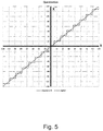
- Fig.5 shows an example of the application of a quantization algorithm for a compression method according to the invention where the input binary data values comprise data values between -127 and +127.
- the range of values is divided in 2 b+1 -1 subranges (in the example of Fig. 5 , 15 subranges), instead of 2 b+1 subranges (in the example of Fig. 3 , 16 subranges).
- the quantization step size is slightly larger than in the prior art (the examples of Fig. 1, 2 , 3 and 4 all have a quantization step size of 16).
- the table below shows the resulting subranges, for positive values of x (i.e. the upper right quarter of Fig.
- + 1 2
- the operation may be achieved with two additions and two binary shifts, the latter being free in logic gates.
- a hardware configuration for performing these operations is show on Fig. 6 . Shift operations are easy to implement with logic gates. In the shift operations, the fractional bits must be kept.
- the compression may be performed with a lookup-table. The lookup-table method is most convenient when B is not too large.
- the lookup table may be obtained by applying the method of paragraph [0014] to all integers between 0 and 2 B -1.
- a set of typical test images have been compressed according to the method 2 (having a dead zone, "DZ") and the invention.
- the signal to noise ratio PSNR between the compressed image and original image is compared for sixteen test images.
- the table below shows that the method of the invention has an improvement for all images of the test set.
- PSNR DZ PSNR invention improv Image_001.png 32.95 34.45 1.50 Image_002.png 42.60 44.03 1.43 Image_003.png 42.57 43.95 1.38 Image_004.png 37.31 38.49 1.18 Image_005.png 38.23 39.41 1.18 Image_006.png 35.01 36.18 1.17 Image_007.png 41.37 42.49 1.12 Image_008.png 40.46 41.57 1.11 Image_009.png 41.08 42.15 1.07 Image_010.png 33.11 34.00 0.89 Image_011.png 39.27 40.16 0.89 Image_012.png 29.90 30.76 0.86 Image_013.png 36.68 37.54 0.86 Image_014.png 36.16 36.99 0.83 Image_015.png 31.38 32.20 0.82 Image_016.png 34.11 34.92 0.81
- a second component of the invention is related to the compression of input binary data such as video streams.
- Methods of data compression on values that are correlated, typically image compression, include the two following characteristics:
- the value of GCLI is determined.
- the quantization method is applied, and the resulting data are put in the output binary data, together with the values of GCLI.
- the GTLI having the same value for all sets of the data, is transmitted or stored only once.
- the GCLI values are used to summarize the data in the rate allocation, since they adequately fulfil the requirements mentioned before. To illustrate the reasoning, a possible architecture is shown in Fig. 8 , where:
- GTLI Greatest Trimmed Level Index
- the GRQ quantization preserves the zero values and ensures that the number of bits to encode the quantized values remains b, thus allowing an easy control of the output rate in function of the quantization through the parameter GTLI (for each subband) in the rate allocation process. As shown before, it does not suffer from a larger dead zone like other quantization schemes that preserve the number of bits and the zero values, and thus has a lower average error in the decoding.
- the method of the invention achieves compression of a set of coefficients in a few steps, in an extremely simple and effective way for hardware implementation.
- This compression scheme encodes several pixels at the same time, parallel encoding of multiple pixels is intrinsic to the proposed codec. It allows reaching high pixel rate with a low complexity codec, while keeping good compression efficiency.
Description
- The invention relates to a method and device for compression and decompression of binary data and to a method for storing/retrieving or transmitting/receiving images or video data streams using said method for compression and decompression.
- The audio-visual market is rapidly evolving to ultra-high resolutions (8192 x 4320 pixels) and higher frame rates. Real-time hardware systems therefore need to process data at higher and higher pixel rate. There is a need to limit the storage capacity required for storing video images and/or channel bandwidth for transmitting video images. To address this problem, a known solution is reducing the number of bits used for coding a binary value. Reducing the number of bits of a value encoded on B bits to a value coded on b bits with B > b, is an operation called quantization.
- A known method to quantize numerical values is described below. Other methods exist that are adapted to particular value characteristics, for example to quantize logarithmic or exponential values. Here we will describe the general case. If [0, Nmax[ is the interval boundaries of any value to quantize, and dq the quantization step size (the gap between two successive values of the quantized set), a value x is quantized into a value x' as follows:

The interval is partitioned into (Nmax/dq)+1 subranges, each of which corresponding to a quantized value. The ½ term centres the subranges correctly on their respective sub-interval. A quantized value x' is dequantized into a value x" as follows:
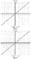
Fig. 1 represents the values of x on the horizontal axis, the values of x being integers between zero and 127, i.e. Nmax = 128. The quantization step size, i.e. the gap between two successive values of the quantized set, dq is equal to 16. The interval [0, 128 [ is partitioned in 9 subranges. The plain line represents the dequantized values x". The dashed line represents the original, unquantized values. The values of x from 0 to 7 correspond to dequantizedvalue 0. The values of x from 8 to 23 correspond to dequantizedvalue 16, etc., up to the values of x from 120 to 127 corresponding to dequantizedvalue 128.
When values are signed, the principle remains the same. Values to quantize being within the ]-Nmax,Nmax[ interval, the sign xs is separated from the absolute value y and one proceeds as above:


Fig.2 represents the corresponding relation between x and x". The inverse quantization reconstructs the value x" in the original domain. Since some amount of precision has been lost, the resulting values are different and the difference is called the truncation error ε (gap between the plain and the dashed line)

- In the case where the input and output data are binary values, the situation is as follows: To encode an integer value x on B+1 bits, one bit is used to indicate the sign (e.g. 0 for positive, 1 for negative), and B bits to represent the absolute value of x. Similarly, b bits are used to encode the quantized absolute value y' and one bit xs to indicate its sign:


- The ½ term in equation (1) requires one extra bit to code the quantized value and instead of removing B-b bits the quantization only removes B-b-1 bits. One can see on
Fig. 1 that we have 9 subranges, and corresponding 9 values of y' ranging from 0 to 8, and requiring four bits for coding the quantized values. InFig. 2 , we have 17 subranges, and corresponding 17 values for y', ranging from -8 to +8, requiring five bits for coding, depending on the value of x. This is not desirable since a property sought in compression is the ability to determine precisely how many bits will be required to code the quantized values before transmitting or storing them. This required extra bit has an impact when the level of quantization (how many bits are removed) is chosen in function of the target output rate (how many bits are output). Since adjacent values are often correlated and contained in the same range, compression algorithms take advantage of this feature to regroup them in blocks that are encoded with the same numbers of bits. This number is set by the highest absolute value, assuming those values are centred on zero. A unique quantization step size dq is used for each block, reducing the amount of information added to the compressed code stream for the inverse quantization procedure, which needs to retrieve the dq quantization step size in order to restore the quantized values. Therefore any change in the number of output bits after the selection of this quantization step size will produce an incorrect rate, or require an iterative process to keep the rate under control.
For example, if b<digits> is the binary notation of a value, and if we consider a block of four 4-bit values,


- According to a known method having fixed width quantization (method 1), one can avoid this and keep the number of bits constant. This is done by omitting the ½ term in the quantization:


The number of values of y' is 16, so y' can be represented with 4 bits, i.e. without extra bit. As shown onFig.3 , the output values are still centred but there is no zero value in the output values. Because of the corrective term, values jump from -dq/2 to dq/2. In the presence of small values around zero, this produces a quantized "chequered flag" pattern (+dq/2,-dq/2,+dq/2,-dq/2,+dq/2,-dq/2, ...), which, most of the time, is not desired.Fig.10 shows an example where a set of binary values x having all small values (-2, -1, 0, +1, +2) represented as a dashed line results in dequantized values being either +8 or -8 (plain line). - A known method, with a dead zone around zero (method 2) allows zero values, and solves the problem of
method 1. A dead zone is introduced in the inverse quantization (SeeFig.4 ): all input values of x between -16 and +16 result in a dequantized value of zero. The number of values of y' is 15, so y' can be represented with 4 bits, i.e. without extra bit.

- The two methods of binary value quantization discussed above can be implemented efficiently in software or in logic gates, yet they are suffering from different issues. Either the number of bits necessary to encode the truncated values may change depending on the truncation level, the zero could not be properly reconstructed by the inverse operation (method 1), or the inverse quantization introduces a dead zone around zero (method 2).
-
US20070160138 discloses a method for encoding and decoding video data, including film grain information, using a quantization method with a controllable dead zone. The size of the quantization step size for the smallest coefficient values is adjusted, and therefore, the quantization is non-uniform. The choice of the quantization step size in relation to the number of bits available for the quantized coefficients is not addressed. - Document "Near-lossless complexity-scalable embedded compression algorithm for cost reduction in DTV receivers, van der Schaar, M. et al., IEEE Transactions on Consumer Electronics archive Volume 46 " discusses quantization methods. One quantization method involves quantization intervals that are limited to powers of 2 (see
equation 5, page 928) and therefore have the disadvantages of the methods discussed above. Another quantization method (seeequation 6, page 929) is more complex and designed for MPEG-2. -
EP2819412 discloses a quantization method, where, for a set of binary input data values, a bias value is selected and only the offset from the bias value is output, as binary output values coded on less bits than the input data values. AlsoEP1750447 discloses a quantisation method where the sign of the value to be quantised is output separately and shifting operations are carried out. - Many encoding methods are known, which attempt to achieve a better compression. However, these methods imply an increased computational and storage requirement, which make them inapplicable to the high resolutions and high frame rates.
- It is an object of the present invention to provide a method and device for compressing a set of input binary data values into a corresponding set of output data values coded in a smaller number of bits, not having the drawback of the methods discussed above, and a corresponding method and device for decompressing a set of input binary data values.
- The invention is defined by the independent claims. The dependent claims define advantageous embodiments.
- According to a first aspect of the invention, there is provided a method for compressing a set of input binary data values x, all coded in a same number B of bits, without counting the sign bit when the input binary data values comprise negative values, comprising the step of determining a corresponding set of output data values x', all coded in a smaller number b of bits, without counting a sign bit, wherein the set of compressed output data values x' is obtainable by the steps of:
- a) for each input binary data value x, determining y as follows:
- (i) If the set of input binary data values comprises negative values, determining y, being the absolute value of x, and xs, being the sign of x, coded in one bit;
- (ii) If the set of input binary data values comprises no negative values, determining y, being the value of x;
- b) computing the quantization step size dq

- c) dividing the range of values of y, [0, 2B-1[, in 2b subranges,
- the first subrange being [0, INT(dq/2)[
- the ith subrange being [INT((i-3/2)*dq)+1, INT((i-1/2)*dq)[, for i going from 2 to 2b
- d) determining, for each value of y, the subrange i wherefrom it is an element and computing y'=i-1;
- e) If the set of input binary data values comprises negative values,
- for each input binary data value x, determining x', being the value of y' together with xs;
- f) If the set of input binary data values comprises no negative values,
- for each input binary data value x, determining x', being the value of y'.
- In an embodiment, the steps (b) to (d) are implemented by performing the steps of
- right-shifting y by B-b bits giving first result;
- right-shifting y by B+1 bits giving second result;
- subtracting second result from first result giving third result;
- adding 0,5 giving fourth result;
- selecting the positive and zero-weight bits of fourth result, giving y'.
- In another embodiment, the method comprises the steps of
- obtaining a lookup table containing, for each of the 2B values of y, the corresponding value of y';
- determining for each value of y in said set, the corresponding value of y', at index y in said table.
- According to a second aspect of the invention, there is provided a method for compressing input binary data comprising input binary data values into an output binary data, said output binary data having a volume smaller than a limit, the method comprising the steps of
- grouping said input binary data values in sets of NGCLI input binary data values;
- for each of said sets of NGCLI input binary data values:
- determine the GCLI, being the index of the highest non-zero bit in said set, without counting a sign bit
- selecting a value of GTLI such that counting GCLI-GTLI bits for all said input binary data values produces output binary data having a volume smaller than said limit;
- for each of said sets of NGCLI input binary data values:
- applying the method of any of
claims 1 to 3, with B=GCLI and b=MAX(GCLI-GTLI,0)
- applying the method of any of
- producing output binary data comprising the GTLI and, for each of said sets of NGCLI input binary data value, the value of the GCLI and the NGCLI quantized values x'.
- In the trivial case where b=0, which may occur in execution of the method of the second aspect of the invention, then the output data values have a value zero and are coded on zero bits. In that case the output binary data for the set only contain the GCLI.
- This method is applied advantageously where said input binary data is resulting from a decorrelative transform of video data.
- NGCLI may be comprised between 4 and 16, and preferably equal to 4.
- According to a third aspect of the invention, there is provided a method for decompressing a set of input binary data values x', all coded in a same number b of bits, without counting a possible sign bit, into a corresponding set of output data values x", all coded in a larger number B of bits, without counting a possible sign bit, comprising the steps of:
- a) computing

- b) if the set of input binary data values comprises negative values, for each input binary data value x', determining y', being the absolute value of x', and x's, being the sign of x', coded in one bit;
- c) If the set of input binary data values comprises no negative values, for each input binary data value x', determining y', being the value of x';
- d) computing for each y'

- e) If the set of input binary data values comprises negative values, for each input binary data value y', determining x", being the value of y" together with x's;
- f) If the set of input binary data values comprises no negative values, for each input binary data value x', determining x", being the value of y".
- In the decompression method said step d) may comprise the steps of
- i. left-shifting y' by B-b bits giving first result;
- ii. right-shifting first result by b+1 bits giving second result;
- iii. adding second result to first result giving sum result;
- iv. copying second result to first result;
- v. repeating steps ii.- iv. until second result is lower than zero;
- vi. computing y" as the integer part of sum result.
- In the decompression method said step d) may also comprise the steps of
- i. left-shifting y' by B-b bits giving first result;
- ii. right-shifting first result by b+1 bits giving second result;
- iii. adding second result to first result giving sum result;
- iv. computing y" as the integer part of sum result.
- The decompression method may comprise the steps of
- obtaining a lookup table containing, for each of the 2b values of y', the corresponding value of y";
- determining for each value of y' in said set, the corresponding value of y", at index y' in said table.
- According to a fourth aspect of the invention, there is provided a method for decompressing input binary data comprising sets of NGCLI input binary data value, each set comprising the value of B, B being the number of bit of decompressed binary data values, the value of b, b being the number of bits of said input binary data values, without counting a possible sign bit, the method comprising the steps of
- applying the method of any of
claims 7 to 10, for obtaining decompressed binary data values; - producing output binary data comprising said decompressed binary data values.
- Said decompressed binary data values may be completed with a number of '0' bits for obtaining words having a given length.
- The invention also relates to the use of a decompression method according the invention for decompressing a set of input binary data values x' obtainable by the compression method of the invention.
- The invention also relates to a device for compressing a set of input binary data values x, all coded in a same number of bits, into a corresponding set of output data values x', all coded in a smaller number of bits, comprising program code for executing the compression method of the invention.
- The invention also relates to a device for compressing a set of input binary data values x, all coded in a same number of bits, into a corresponding set of output data values x', all coded in a smaller number of bits, comprising hardware for executing the compression method the invention.
- The invention also relates to a device for decompressing a set of input binary data values x', all coded in a same number of bits, into a corresponding set of output data values x", all coded in a larger number of bits, comprising program code for executing the decompression method the invention.
- The invention also relates to a device for decompressing a set of input binary data values x', all coded in a same number of bits, into a corresponding set of output data values x", all coded in a larger number of bits, comprising hardware for executing the decompression method of the invention.
- The methods of the invention apply to sets of input binary data values having all positive integer values and to input binary data values having positive and negative values. In the latter case, it is assumed that the negative values are represented by a sign bit and a magnitude (absolute value). If another representation is used, e.g. ones'-complement or two's-complement, it is a straightforward operation known to the man skilled in the art to translate the input binary data values to their sign-magnitude representation.
- These and further aspects of the invention will be explained in greater detail by way of example and with reference to the accompanying drawings in which:
-
Fig.1 represents reconstructed values x" in plain lines and original values x in dashed lines, in function of original values x, for a known quantization method applicable to natural values. Nmax=128, dq=16 ; -
Fig.2 represents reconstructed values x" in plain lines and original values x in dashed lines, in function of original values x, for a known quantization method applicable to signed values; -
Fig.3 represents reconstructed values x" in plain lines and original values x in dashed lines, in function of original values x, for a known quantization method applicable to binary signed values, with fixed-width quantization (method 1); -
Fig.4 represents reconstructed values x" in plain lines and original values x in dashed lines, in function of original values x, for a known quantization method applicable to binary signed values, with dead zone (method 2); -
Fig.5 represents reconstructed values x" in plain lines and original values x in dashed lines, in function of original values x, for a method for compressing according to the invention; -
Fig.6 represents schematically a device for quantization for a method for compressing according to an embodiment of the invention; -
Fig.7 represents schematically a device for dequantization for a method for decompressing according to an embodiment of the invention; -
Fig.8 represents schematically a method according to a preferred embodiment of the invention. -
Fig.9 represents exemplary data set where the method of the invention is applied. -
Fig.10 illustrates a problem with fixed width quantization (method 1), as discussed above. - The drawings of the figures are neither drawn to scale nor proportioned. Generally, identical components are denoted by the same reference numerals in the figures.
- A first component of the invention is a quantization algorithm which offers an advantage in the scope of image compression, requires no extra bit and provides a solution to the problems mentioned in relation to
method 1 andmethod 2 above. The quantization algorithm will be referred to as "GRQ". -
Fig.5 shows an example of the application of a quantization algorithm for a compression method according to the invention where the input binary data values comprise data values between -127 and +127. The number of bits used for coding the absolute values of x is 7 bits, i.e. B=7. The number of absolute quantized values is 8, i.e. the quantized values can be coded on 3 bits, and b=3.
According to the invention, the range of values is divided in 2b+1-1 subranges (in the example ofFig. 5 , 15 subranges), instead of 2b+1 subranges (in the example ofFig. 3 , 16 subranges). The quantization step size dq is:
Fig. 1, 2 ,3 and 4 all have a quantization step size of 16).
The table below shows the resulting subranges, for positive values of x (i.e. the upper right quarter ofFig. 5 )Subrange i first value of x Last value of x nb of values 1 0 8 9 2 9 25 17 3 26 42 17 4 43 59 17 5 60 76 17 6 77 93 17 7 94 110 17 8 111 127 17 128
The quantization algorithm always produces the exact number b of bits in the quantized values, and thus is appropriate in compression schemes featuring a rate allocation since it guarantees a predictable rate in function of the quantization level, with a better quality. This makes it the ideal quantization algorithm to be used in conjunction with the second component of this invention, the GCLI values (Greatest Coded Line Index), which allow an efficient rate allocation method, as explained in paragraph [0040]. - The quantized values are obtained by equation

A hardware configuration for performing these operations is show onFig. 6 . Shift operations are easy to implement with logic gates. In the shift operations, the fractional bits must be kept. As an alternative to the register-shift method, the compression may be performed with a lookup-table. The lookup-table method is most convenient when B is not too large. The lookup table may be obtained by applying the method of paragraph [0014] to all integers between 0 and 2B-1. - The inverse quantization values are obtained by equation


Fig. 7 . - In summary, the operation has the same complexity level than what is done in the state of the art:
- the quantization is subtracting two shifted values of |x| then adding a bit after the LSB
- the inverse quantization is a concatenation of shifted values of y' The quality of the reconstructed values is higher given the same level of quantization, which means the invention provides an increased quality at the same bitrate in the transmission for a compression algorithm.
- A set of typical test images have been compressed according to the method 2 (having a dead zone, "DZ") and the invention. The signal to noise ratio PSNR between the compressed image and original image is compared for sixteen test images. The table below shows that the method of the invention has an improvement for all images of the test set.
filename PSNR DZ PSNR invention improv Image_001.png 32.95 34.45 1.50 Image_002.png 42.60 44.03 1.43 Image_003.png 42.57 43.95 1.38 Image_004.png 37.31 38.49 1.18 Image_005.png 38.23 39.41 1.18 Image_006.png 35.01 36.18 1.17 Image_007.png 41.37 42.49 1.12 Image_008.png 40.46 41.57 1.11 Image_009.png 41.08 42.15 1.07 Image_010.png 33.11 34.00 0.89 Image_011.png 39.27 40.16 0.89 Image_012.png 29.90 30.76 0.86 Image_013.png 36.68 37.54 0.86 Image_014.png 36.16 36.99 0.83 Image_015.png 31.38 32.20 0.82 Image_016.png 34.11 34.92 0.81 - A second component of the invention is related to the compression of input binary data such as video streams. Methods of data compression on values that are correlated, typically image compression, include the two following characteristics:
- data are quantized to reduce the amount of bits to store or transmit to the decoder;
- information on how the data have been quantized (B-b) is inserted in front of the quantized data, since it will be required by the decoder to apply the inverse quantization. The resulting information is called a codestream.
- be concise: usually the compression must be achieved as quickly as possible, and the higher the amount of data processed by the rate allocation, the slower it will take;
- be representative of the quality: the rate allocation optimizes the quality for a given bitrate, it must be able to estimate the quality loss in function of the quantization level;
- be efficiently transcodable into the codestream: the decoder needs enough information to reconstruct the data (e.g. apply the correct inverse quantization on each block).
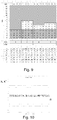
- The GCLI value of a vector or block of NGCLI data is the maximum number of bits necessary to code the magnitude of its values in binary representation. So -6 is coded b110 (plus one sign bit), and requires 3 bits to encode its absolute value. A block with the values (4,9,2,5) has a GCLI=4, since the maximum is 9 and is coded b1001. Zero requires zero bit to encode, and does not need a sign. Further examples are shown in
Fig. 9 . Input binary data, comprising 16 binary data values all coded in 15 bits plus sign bits are represented. As may occur in decorrelated data, many data values are small and most of the most significant bits are at zero (represented as grey area). The input data are grouped in sets of four (NGCLI=4) words. For each of these sets, the value of GCLI is determined. For the whole set of input data, a value of GTLI (here GTLI=4) is selected so that the size of the data resulting from the compression (a different value of b for each set) will meet the limitation of the available bandwidth of storage size. For each of the sets, the quantization method is applied, and the resulting data are put in the output binary data, together with the values of GCLI. The GTLI, having the same value for all sets of the data, is transmitted or stored only once. The GCLI values are used to summarize the data in the rate allocation, since they adequately fulfil the requirements mentioned before. To illustrate the reasoning, a possible architecture is shown inFig. 8 , where: - the correlated data is grouped in blocks of NGCLI values, from which are extracted the GCLI's;
- the GCLI values are used by the rate allocation to determine the quantization levels;
- the quantization is applied to the data (GRQ);
- the codestream is created from the compressed data and the information required to decompress it - in this example, the quantization levels and the GCLI's.
- The GCLI's are concise, one value represents the maximum logarithm in a block containing multiple values, so it will not require many bits to encode: typically, 16 bits are enough to code coefficients in a DWT, which means that 4-bit GCLI values can be used. If NGCLI=4, one 4-bit GCLI represents 4 coefficients of 16 bits in the rate allocation, which is a ratio of 1 to 64. This is efficient since neighbor values are correlated and will have similar magnitudes, so using the same number of bits to code them all is near-optimal. This means the GCLI's provide the rate allocation with concise information to compute the output rate in function of the truncation level. Furthermore, the GCLI values actually provide local quantization step sizes dq, as illustrated in
Fig. 9 . The truncated part or GTLI (Greatest Trimmed Level Index) is set individually for each subband like other algorithms, but the maximum number of bits B is set by each GCLI, so for each group of NGCLI data. This last property reduces the number of bits to encode by removing the upper zero MSB's in large blocks, which more than compensate the cost of inserting GCLI information in the output stream (necessary for the inverse quantization). - Using the GCLI method requires a predictable rate in function of the quantization, as explained in paragraph [0004]. The GRQ quantization preserves the zero values and ensures that the number of bits to encode the quantized values remains b, thus allowing an easy control of the output rate in function of the quantization through the parameter GTLI (for each subband) in the rate allocation process. As shown before, it does not suffer from a larger dead zone like other quantization schemes that preserve the number of bits and the zero values, and thus has a lower average error in the decoding.
- The method of the invention achieves compression of a set of coefficients in a few steps, in an extremely simple and effective way for hardware implementation. As this compression scheme encodes several pixels at the same time, parallel encoding of multiple pixels is intrinsic to the proposed codec. It allows reaching high pixel rate with a low complexity codec, while keeping good compression efficiency.
- The present invention has been described in terms of specific embodiments, which are illustrative of the invention and not to be construed as limiting. More generally, it will be appreciated by persons skilled in the art that the present invention is not limited by what has been particularly shown and/or described hereinabove.
- Reference numerals in the claims do not limit their protective scope. Use of the verbs "to comprise", "to include", "to be composed of", or any other variant, as well as their respective conjugations, does not exclude the presence of elements other than those stated. Use of the article "a", "an" or "the" preceding an element does not exclude the presence of a plurality of such elements.
The choice of the data structure processed by the rate allocation is of paramount importance, it has to fulfil these requirements:
Claims (17)
- Method for compressing a set of input binary data values x, all coded in a same number B of bits, without counting the sign bit when the input binary data values comprise negative values, comprising the step of determining a corresponding set of compressed output data values x', all coded in a smaller number b of bits, without counting a sign bit, wherein the set of compressed output data values x' is obtainable by the steps of:a) for each input binary data value x, determining y as follows:(i) If the set of input binary data values comprises negative values, determining y, being the absolute value of x, and xs, being the sign of x, coded in one bit;(ii) If the set of input binary data values comprises no negative values, determining y, being the value of x;b) computing the quantization step size dq
 c) dividing the range of values of y, [0, 2B-1[, in 2b subranges,• the first subrange being [0, INT(dq/2)[• the ith subrange being [INT((i-3/2)*dq)+1, INT((i-1/2)*dq)[, for i going from 2 to 2bd) determining, for each value of y, the subrange i wherefrom it is an element and computing y'=i-1;e) If the set of input binary data values comprises negative values,• for each input binary data value x, determining x', being the value of y' together with xs;f) If the set of input binary data values comprises no negative values,• for each input binary data value x, determining x', being the value of y'.
 - Method according to claim 1, wherein steps (b) to (d) are implemented by performing the steps of• right-shifting y by B-b bits giving first result;• right-shifting y by B+1 bits giving second result;• subtracting second result from first result giving third result;• adding 0,5 giving fourth result;• select the positive and zero-weight bits of fourth result, giving y'.
- Method according to claim 1, comprising the steps of• obtaining a lookup table containing, for each of the 2B values of y, the corresponding value of y';• determining for each value of y in said set, the corresponding value of y', at index y in said table.
- Method for compressing input binary data comprising input binary data values into an output binary data, said output binary data having a volume smaller than a limit, the method comprising the steps of• grouping said input binary data values in sets of NGCLI input binary data values;• for each of said sets of NGCLI input binary data values:- Determine the GCLI, being the index of the highest non-zero bit in said set, without counting a sign bit• selecting a value of GTLI such that counting GCLI-GTLI bits for all said input binary data values produces output binary data having a volume smaller than said limit;• for each of said sets of NGCLI input binary data values:- applying the method of any of claims 1 to 3, with B=GCLI and b=MAX(GCLI-GTLI,0)• producing output binary data comprising the GTLI and for each of said sets of NGCLI input binary data value, the value of the GCLI and the NGCLI quantized values x'.
- Method according to claim 4 where said input binary data is resulting from a decorrelative transform of video data.
- Method according to any of claims 4 to 5 where NGCLI is comprised between 4 and 16, and preferably equal to 4.
- Method for decompressing a set of input binary data values x', all coded in a same number b of bits, without counting a possible sign bit, into a corresponding set of output data values x", all coded in a larger number B of bits, without counting a possible sign bit, comprising the steps of:a) computing
 b) If the set of input binary data values comprises negative values, for each input binary data value x', determining y', being the absolute value of x', and x's, being the sign of x', coded in one bit;c) If the set of input binary data values comprises no negative values, for each input binary data value x', determining y', being the value of x';d) computing for each y'
 e) If the set of input binary data values comprises negative values, for each input binary data value y', determining x", being the value of y" together with x's;f) If the set of input binary data values comprises no negative values, for each input binary data value x', determining x", being the value of y".
 - Method according to claim 7, wherein said step d) comprises the steps ofi. left-shifting y' by B-b bits giving first result;ii. right-shifting first result by b+1 bits giving second result;iii. adding second result to first result giving sum result;iv. copying second result to first result;v. repeating steps ii.- iv. until second result is lower than zero;vi. computing y" as the integer part of sum result.
- Method according to claim 7, wherein b ≤ B/2 and said step d) comprises the steps ofi. left-shifting y' by B-b bits giving first result;ii. right-shifting first result by b+1 bits giving second result;iii. adding second result to first result giving sum result;iv. computing y" as the integer part of sum result.
- Method according to claim 7, comprising the steps of• obtaining a lookup table containing, for each of the 2b values of y', the corresponding value of y";• determining for each value of y' in said set, the corresponding value of y", at index y' in said table.
- Method for decompressing input binary data comprising sets of NGCLI input binary data value, each set comprising the value of B, B being the number of bit of decompressed binary data values, the value of b, b being the number of bits of said input binary data values, without counting a possible sign bit, the method comprising the steps of• applying the method of any of claims 7 to 10, for obtaining decompressed binary data values;• producing output binary data comprising said decompressed binary data values.
- Method for decompressing according to claim 11 where said decompressed binary data values are completed with a number of '0' bits for obtaining words having a given length.
- Use of a decompression method according to any of claims 7 to 10 for decompressing a set of input binary data values x' obtainable by the compression method of any of claims 1 to 6.
- Device for compressing a set of input binary data values x, all coded in a same number of bits, into a corresponding set of output data values x', all coded in a smaller number of bits, comprising program code for executing the method of any of claims 1 to 3.
- Device for compressing a set of input binary data values x, all coded in a same number of bits, into a corresponding set of output data values x', all coded in a smaller number of bits, comprising hardware for executing the method of any of claims 2 or 3.
- Device for decompressing a set of input binary data values x', all coded in a same number of bits, into a corresponding set of output data values x", all coded in a larger number of bits, comprising program code for executing the method of any of claims 7 to 10.
- Device for decompressing a set of input binary data values x', all coded in a same number of bits, into a corresponding set of output data values x", all coded in a larger number of bits, comprising hardware for executing the method of any of claims 7 to 10.
Priority Applications (4)
| Application Number | Priority Date | Filing Date | Title |
|---|---|---|---|
| EP16153212.2A EP3200455B1 (en) | 2016-01-28 | 2016-01-28 | Method and device for compression and decompression of binary data |
| CN201710055556.4A CN107018430B (en) | 2016-01-28 | 2017-01-25 | The method and apparatus of compression and decompression for binary data |
| US15/414,831 US10334246B2 (en) | 2016-01-28 | 2017-01-25 | Method and device for compression and decompression of binary data |
| JP2017012083A JP6431556B2 (en) | 2016-01-28 | 2017-01-26 | Method and apparatus for compressing and decompressing binary data |
Applications Claiming Priority (1)
| Application Number | Priority Date | Filing Date | Title |
|---|---|---|---|
| EP16153212.2A EP3200455B1 (en) | 2016-01-28 | 2016-01-28 | Method and device for compression and decompression of binary data |
Publications (2)
| Publication Number | Publication Date |
|---|---|
| EP3200455A1 EP3200455A1 (en) | 2017-08-02 |
| EP3200455B1 true EP3200455B1 (en) | 2018-09-05 |
Family
ID=55361327
Family Applications (1)
| Application Number | Title | Priority Date | Filing Date |
|---|---|---|---|
| EP16153212.2A Active EP3200455B1 (en) | 2016-01-28 | 2016-01-28 | Method and device for compression and decompression of binary data |
Country Status (4)
| Country | Link |
|---|---|
| US (1) | US10334246B2 (en) |
| EP (1) | EP3200455B1 (en) |
| JP (1) | JP6431556B2 (en) |
| CN (1) | CN107018430B (en) |
Families Citing this family (3)
| Publication number | Priority date | Publication date | Assignee | Title |
|---|---|---|---|---|
| EP3556097B1 (en) * | 2016-12-19 | 2021-12-15 | Fraunhofer-Gesellschaft zur Förderung der angewandten Forschung e.V. | Image coding using a subband dependent prediction adaption for gcli entropy coding |
| JPWO2019013228A1 (en) | 2017-07-11 | 2020-05-07 | 三菱ケミカル株式会社 | Silica powder storage package and inspection kit using the same |
| CN111385578B (en) * | 2018-12-28 | 2021-06-01 | 北京图森智途科技有限公司 | Data decompression method applied to FPGA, imaging device and automobile |
Family Cites Families (15)
| Publication number | Priority date | Publication date | Assignee | Title |
|---|---|---|---|---|
| JP3689437B2 (en) * | 1992-10-29 | 2005-08-31 | ソニー株式会社 | Image signal encoding method and apparatus |
| JP2795300B2 (en) * | 1992-12-16 | 1998-09-10 | 日本電気株式会社 | Image coding method |
| JP2827997B2 (en) * | 1995-12-28 | 1998-11-25 | 日本電気株式会社 | Image signal Hadamard transform encoding device and decoding device |
| US6339614B1 (en) * | 1996-12-20 | 2002-01-15 | Intel Corporation | Method and apparatus for quantizing and run length encoding transform coefficients in a video coder |
| KR100433516B1 (en) * | 2000-12-08 | 2004-05-31 | 삼성전자주식회사 | Transcoding method |
| EP1750447A3 (en) * | 2001-11-27 | 2009-07-22 | Samsung Electronics Co., Ltd. | Method and apparatus for encoding and decoding key data |
| EP1761065A3 (en) * | 2001-11-27 | 2009-08-26 | Samsung Electronics Co., Ltd. | Method and apparatus for encoding and decoding key data |
| JP4068537B2 (en) * | 2003-09-03 | 2008-03-26 | 日本電信電話株式会社 | Hierarchical coded bitstream requantization method and apparatus, hierarchical coded bitstream requantization program, and recording medium recording the program |
| EP1564997A1 (en) * | 2004-02-12 | 2005-08-17 | Matsushita Electric Industrial Co., Ltd. | Encoding and decoding of video images based on a quantization with an adaptive dead-zone size |
| US8045614B2 (en) * | 2005-05-11 | 2011-10-25 | Dolby Laboratories Licensing Corporation | Quantization control for variable bit depth |
| JP4624321B2 (en) * | 2006-08-04 | 2011-02-02 | 株式会社メガチップス | Transcoder and coded image conversion method |
| CA2832086C (en) * | 2011-04-15 | 2018-10-23 | Blackberry Limited | Methods and devices for coding and decoding the position of the last significant coefficient |
| RU2602782C2 (en) * | 2012-06-28 | 2016-11-20 | Нек Корпорейшн | Method of video quantization parameter encoding, method of video quantization parameters decoding and corresponding devices and programs |
| WO2014193630A1 (en) * | 2013-05-30 | 2014-12-04 | Intel Corporation | Quantization offset and cost factor modification for video encoding |
| WO2014205730A1 (en) * | 2013-06-27 | 2014-12-31 | 北京大学深圳研究生院 | Avs video compressing and coding method, and coder |
-
2016
- 2016-01-28 EP EP16153212.2A patent/EP3200455B1/en active Active
-
2017
- 2017-01-25 US US15/414,831 patent/US10334246B2/en active Active
- 2017-01-25 CN CN201710055556.4A patent/CN107018430B/en active Active
- 2017-01-26 JP JP2017012083A patent/JP6431556B2/en active Active
Also Published As
| Publication number | Publication date |
|---|---|
| EP3200455A1 (en) | 2017-08-02 |
| JP2017135708A (en) | 2017-08-03 |
| US10334246B2 (en) | 2019-06-25 |
| US20170223354A1 (en) | 2017-08-03 |
| CN107018430B (en) | 2019-05-31 |
| CN107018430A (en) | 2017-08-04 |
| JP6431556B2 (en) | 2018-11-28 |
Similar Documents
| Publication | Publication Date | Title |
|---|---|---|
| US10045034B2 (en) | System and method for using pattern vectors for video and image coding and decoding | |
| US7003168B1 (en) | Image compression and decompression based on an integer wavelet transform using a lifting scheme and a correction method | |
| US8767823B2 (en) | Method and apparatus for frame memory compression | |
| US6408026B1 (en) | Deadzone quantization method and apparatus for image compression | |
| US6813387B1 (en) | Tile boundary artifact removal for arbitrary wavelet filters | |
| JP2008526072A (en) | Scalable coding | |
| JP2010503254A (en) | Apparatus and method for encoding data signal, and apparatus and method for decoding data signal | |
| JPH10243396A (en) | Adaptive quantization method and method for encoding video signal data and system for encoding sampling-processed video signal data | |
| EP3200455B1 (en) | Method and device for compression and decompression of binary data | |
| AU2018298758B2 (en) | Method and device for digital data compression | |
| WO2016025282A1 (en) | Method for coding pulse vectors using statistical properties | |
| US10212421B2 (en) | Method and device for digital data compression with sign bit removal | |
| Singh et al. | A Review on Latest Techniques of Image Compression | |
| EP3180862B1 (en) | Method for coding pulse vectors using statistical properties | |
| Sahooinst et al. | Haar wavelet transform image compression using various run length encoding schemes | |
| US7570818B2 (en) | Method for deblocking and transcoding a media stream | |
| Rapesta et al. | Cell-based 2-step scalar deadzone quantization for JPEG2000 | |
| US20090074059A1 (en) | Encoding method and device for image data | |
| Andre et al. | Entropy-based distortion measure for image coding | |
| Simić et al. | Improved algorithm for grayscale image compression based on multimode coding algorithm | |
| Ahmed | DCT Image Compression by Run-Length and Shift Coding Techniques. | |
| El–said | Efficient DCT–based image compression technique | |
| El-said et al. | Image compression technique for low bit rate transmission | |
| Yu et al. | Lossless Image Compression using Differential Pulse Code Modulation and Its purpose | |
| Yeo et al. | Analysing JPEG coding with masking |
Legal Events
| Date | Code | Title | Description |
|---|---|---|---|
| PUAI | Public reference made under article 153(3) epc to a published international application that has entered the european phase |
Free format text: ORIGINAL CODE: 0009012 |
|
| STAA | Information on the status of an ep patent application or granted ep patent |
Free format text: STATUS: THE APPLICATION HAS BEEN PUBLISHED |
|
| AK | Designated contracting states |
Kind code of ref document: A1 Designated state(s): AL AT BE BG CH CY CZ DE DK EE ES FI FR GB GR HR HU IE IS IT LI LT LU LV MC MK MT NL NO PL PT RO RS SE SI SK SM TR |
|
| AX | Request for extension of the european patent |
Extension state: BA ME |
|
| STAA | Information on the status of an ep patent application or granted ep patent |
Free format text: STATUS: REQUEST FOR EXAMINATION WAS MADE |
|
| 17P | Request for examination filed |
Effective date: 20170926 |
|
| RBV | Designated contracting states (corrected) |
Designated state(s): AL AT BE BG CH CY CZ DE DK EE ES FI FR GB GR HR HU IE IS IT LI LT LU LV MC MK MT NL NO PL PT RO RS SE SI SK SM TR |
|
| STAA | Information on the status of an ep patent application or granted ep patent |
Free format text: STATUS: EXAMINATION IS IN PROGRESS |
|
| 17Q | First examination report despatched |
Effective date: 20171208 |
|
| GRAP | Despatch of communication of intention to grant a patent |
Free format text: ORIGINAL CODE: EPIDOSNIGR1 |
|
| STAA | Information on the status of an ep patent application or granted ep patent |
Free format text: STATUS: GRANT OF PATENT IS INTENDED |
|
| INTG | Intention to grant announced |
Effective date: 20180425 |
|
| GRAS | Grant fee paid |
Free format text: ORIGINAL CODE: EPIDOSNIGR3 |
|
| GRAA | (expected) grant |
Free format text: ORIGINAL CODE: 0009210 |
|
| STAA | Information on the status of an ep patent application or granted ep patent |
Free format text: STATUS: THE PATENT HAS BEEN GRANTED |
|
| AK | Designated contracting states |
Kind code of ref document: B1 Designated state(s): AL AT BE BG CH CY CZ DE DK EE ES FI FR GB GR HR HU IE IS IT LI LT LU LV MC MK MT NL NO PL PT RO RS SE SI SK SM TR |
|
| REG | Reference to a national code |
Ref country code: GB Ref legal event code: FG4D |
|
| REG | Reference to a national code |
Ref country code: CH Ref legal event code: EP |
|
| REG | Reference to a national code |
Ref country code: AT Ref legal event code: REF Ref document number: 1039299 Country of ref document: AT Kind code of ref document: T Effective date: 20180915 |
|
| REG | Reference to a national code |
Ref country code: IE Ref legal event code: FG4D |
|
| REG | Reference to a national code |
Ref country code: DE Ref legal event code: R096 Ref document number: 602016005233 Country of ref document: DE |
|
| REG | Reference to a national code |
Ref country code: NL Ref legal event code: FP |
|
| REG | Reference to a national code |
Ref country code: LT Ref legal event code: MG4D |
|
| PG25 | Lapsed in a contracting state [announced via postgrant information from national office to epo] |
Ref country code: GR Free format text: LAPSE BECAUSE OF FAILURE TO SUBMIT A TRANSLATION OF THE DESCRIPTION OR TO PAY THE FEE WITHIN THE PRESCRIBED TIME-LIMIT Effective date: 20181206 Ref country code: FI Free format text: LAPSE BECAUSE OF FAILURE TO SUBMIT A TRANSLATION OF THE DESCRIPTION OR TO PAY THE FEE WITHIN THE PRESCRIBED TIME-LIMIT Effective date: 20180905 Ref country code: SE Free format text: LAPSE BECAUSE OF FAILURE TO SUBMIT A TRANSLATION OF THE DESCRIPTION OR TO PAY THE FEE WITHIN THE PRESCRIBED TIME-LIMIT Effective date: 20180905 Ref country code: LT Free format text: LAPSE BECAUSE OF FAILURE TO SUBMIT A TRANSLATION OF THE DESCRIPTION OR TO PAY THE FEE WITHIN THE PRESCRIBED TIME-LIMIT Effective date: 20180905 Ref country code: RS Free format text: LAPSE BECAUSE OF FAILURE TO SUBMIT A TRANSLATION OF THE DESCRIPTION OR TO PAY THE FEE WITHIN THE PRESCRIBED TIME-LIMIT Effective date: 20180905 Ref country code: NO Free format text: LAPSE BECAUSE OF FAILURE TO SUBMIT A TRANSLATION OF THE DESCRIPTION OR TO PAY THE FEE WITHIN THE PRESCRIBED TIME-LIMIT Effective date: 20181205 Ref country code: BG Free format text: LAPSE BECAUSE OF FAILURE TO SUBMIT A TRANSLATION OF THE DESCRIPTION OR TO PAY THE FEE WITHIN THE PRESCRIBED TIME-LIMIT Effective date: 20181205 |
|
| REG | Reference to a national code |
Ref country code: AT Ref legal event code: MK05 Ref document number: 1039299 Country of ref document: AT Kind code of ref document: T Effective date: 20180905 |
|
| PG25 | Lapsed in a contracting state [announced via postgrant information from national office to epo] |
Ref country code: AL Free format text: LAPSE BECAUSE OF FAILURE TO SUBMIT A TRANSLATION OF THE DESCRIPTION OR TO PAY THE FEE WITHIN THE PRESCRIBED TIME-LIMIT Effective date: 20180905 Ref country code: HR Free format text: LAPSE BECAUSE OF FAILURE TO SUBMIT A TRANSLATION OF THE DESCRIPTION OR TO PAY THE FEE WITHIN THE PRESCRIBED TIME-LIMIT Effective date: 20180905 Ref country code: LV Free format text: LAPSE BECAUSE OF FAILURE TO SUBMIT A TRANSLATION OF THE DESCRIPTION OR TO PAY THE FEE WITHIN THE PRESCRIBED TIME-LIMIT Effective date: 20180905 |
|
| PG25 | Lapsed in a contracting state [announced via postgrant information from national office to epo] |
Ref country code: AT Free format text: LAPSE BECAUSE OF FAILURE TO SUBMIT A TRANSLATION OF THE DESCRIPTION OR TO PAY THE FEE WITHIN THE PRESCRIBED TIME-LIMIT Effective date: 20180905 Ref country code: EE Free format text: LAPSE BECAUSE OF FAILURE TO SUBMIT A TRANSLATION OF THE DESCRIPTION OR TO PAY THE FEE WITHIN THE PRESCRIBED TIME-LIMIT Effective date: 20180905 Ref country code: IS Free format text: LAPSE BECAUSE OF FAILURE TO SUBMIT A TRANSLATION OF THE DESCRIPTION OR TO PAY THE FEE WITHIN THE PRESCRIBED TIME-LIMIT Effective date: 20190105 Ref country code: PL Free format text: LAPSE BECAUSE OF FAILURE TO SUBMIT A TRANSLATION OF THE DESCRIPTION OR TO PAY THE FEE WITHIN THE PRESCRIBED TIME-LIMIT Effective date: 20180905 Ref country code: ES Free format text: LAPSE BECAUSE OF FAILURE TO SUBMIT A TRANSLATION OF THE DESCRIPTION OR TO PAY THE FEE WITHIN THE PRESCRIBED TIME-LIMIT Effective date: 20180905 Ref country code: RO Free format text: LAPSE BECAUSE OF FAILURE TO SUBMIT A TRANSLATION OF THE DESCRIPTION OR TO PAY THE FEE WITHIN THE PRESCRIBED TIME-LIMIT Effective date: 20180905 Ref country code: CZ Free format text: LAPSE BECAUSE OF FAILURE TO SUBMIT A TRANSLATION OF THE DESCRIPTION OR TO PAY THE FEE WITHIN THE PRESCRIBED TIME-LIMIT Effective date: 20180905 Ref country code: IT Free format text: LAPSE BECAUSE OF FAILURE TO SUBMIT A TRANSLATION OF THE DESCRIPTION OR TO PAY THE FEE WITHIN THE PRESCRIBED TIME-LIMIT Effective date: 20180905 |
|
| PG25 | Lapsed in a contracting state [announced via postgrant information from national office to epo] |
Ref country code: PT Free format text: LAPSE BECAUSE OF FAILURE TO SUBMIT A TRANSLATION OF THE DESCRIPTION OR TO PAY THE FEE WITHIN THE PRESCRIBED TIME-LIMIT Effective date: 20190105 Ref country code: SM Free format text: LAPSE BECAUSE OF FAILURE TO SUBMIT A TRANSLATION OF THE DESCRIPTION OR TO PAY THE FEE WITHIN THE PRESCRIBED TIME-LIMIT Effective date: 20180905 Ref country code: SK Free format text: LAPSE BECAUSE OF FAILURE TO SUBMIT A TRANSLATION OF THE DESCRIPTION OR TO PAY THE FEE WITHIN THE PRESCRIBED TIME-LIMIT Effective date: 20180905 |
|
| REG | Reference to a national code |
Ref country code: DE Ref legal event code: R097 Ref document number: 602016005233 Country of ref document: DE |
|
| PLBE | No opposition filed within time limit |
Free format text: ORIGINAL CODE: 0009261 |
|
| STAA | Information on the status of an ep patent application or granted ep patent |
Free format text: STATUS: NO OPPOSITION FILED WITHIN TIME LIMIT |
|
| PG25 | Lapsed in a contracting state [announced via postgrant information from national office to epo] |
Ref country code: DK Free format text: LAPSE BECAUSE OF FAILURE TO SUBMIT A TRANSLATION OF THE DESCRIPTION OR TO PAY THE FEE WITHIN THE PRESCRIBED TIME-LIMIT Effective date: 20180905 |
|
| 26N | No opposition filed |
Effective date: 20190606 |
|
| PG25 | Lapsed in a contracting state [announced via postgrant information from national office to epo] |
Ref country code: SI Free format text: LAPSE BECAUSE OF FAILURE TO SUBMIT A TRANSLATION OF THE DESCRIPTION OR TO PAY THE FEE WITHIN THE PRESCRIBED TIME-LIMIT Effective date: 20180905 Ref country code: MC Free format text: LAPSE BECAUSE OF FAILURE TO SUBMIT A TRANSLATION OF THE DESCRIPTION OR TO PAY THE FEE WITHIN THE PRESCRIBED TIME-LIMIT Effective date: 20180905 |
|
| REG | Reference to a national code |
Ref country code: CH Ref legal event code: PL |
|
| REG | Reference to a national code |
Ref country code: IE Ref legal event code: MM4A |
|
| PG25 | Lapsed in a contracting state [announced via postgrant information from national office to epo] |
Ref country code: LI Free format text: LAPSE BECAUSE OF NON-PAYMENT OF DUE FEES Effective date: 20190131 Ref country code: CH Free format text: LAPSE BECAUSE OF NON-PAYMENT OF DUE FEES Effective date: 20190131 |
|
| PG25 | Lapsed in a contracting state [announced via postgrant information from national office to epo] |
Ref country code: IE Free format text: LAPSE BECAUSE OF NON-PAYMENT OF DUE FEES Effective date: 20190128 |
|
| PG25 | Lapsed in a contracting state [announced via postgrant information from national office to epo] |
Ref country code: TR Free format text: LAPSE BECAUSE OF FAILURE TO SUBMIT A TRANSLATION OF THE DESCRIPTION OR TO PAY THE FEE WITHIN THE PRESCRIBED TIME-LIMIT Effective date: 20180905 |
|
| PG25 | Lapsed in a contracting state [announced via postgrant information from national office to epo] |
Ref country code: MT Free format text: LAPSE BECAUSE OF NON-PAYMENT OF DUE FEES Effective date: 20190128 |
|
| PG25 | Lapsed in a contracting state [announced via postgrant information from national office to epo] |
Ref country code: CY Free format text: LAPSE BECAUSE OF FAILURE TO SUBMIT A TRANSLATION OF THE DESCRIPTION OR TO PAY THE FEE WITHIN THE PRESCRIBED TIME-LIMIT Effective date: 20180905 |
|
| PG25 | Lapsed in a contracting state [announced via postgrant information from national office to epo] |
Ref country code: HU Free format text: LAPSE BECAUSE OF FAILURE TO SUBMIT A TRANSLATION OF THE DESCRIPTION OR TO PAY THE FEE WITHIN THE PRESCRIBED TIME-LIMIT; INVALID AB INITIO Effective date: 20160128 |
|
| PG25 | Lapsed in a contracting state [announced via postgrant information from national office to epo] |
Ref country code: MK Free format text: LAPSE BECAUSE OF FAILURE TO SUBMIT A TRANSLATION OF THE DESCRIPTION OR TO PAY THE FEE WITHIN THE PRESCRIBED TIME-LIMIT Effective date: 20180905 |
|
| PGFP | Annual fee paid to national office [announced via postgrant information from national office to epo] |
Ref country code: BE Payment date: 20221107 Year of fee payment: 8 |
|
| PGFP | Annual fee paid to national office [announced via postgrant information from national office to epo] |
Ref country code: LU Payment date: 20230123 Year of fee payment: 8 Ref country code: FR Payment date: 20230124 Year of fee payment: 8 |
|
| PGFP | Annual fee paid to national office [announced via postgrant information from national office to epo] |
Ref country code: GB Payment date: 20230119 Year of fee payment: 8 Ref country code: DE Payment date: 20230123 Year of fee payment: 8 |
|
| PGFP | Annual fee paid to national office [announced via postgrant information from national office to epo] |
Ref country code: NL Payment date: 20230119 Year of fee payment: 8 |
|
| PGFP | Annual fee paid to national office [announced via postgrant information from national office to epo] |
Ref country code: NL Payment date: 20240119 Year of fee payment: 9 |
|
| PGFP | Annual fee paid to national office [announced via postgrant information from national office to epo] |
Ref country code: LU Payment date: 20240119 Year of fee payment: 9 |