EP3200432A1 - Method for implementing session border controller pool, and session border controller - Google Patents
Method for implementing session border controller pool, and session border controller Download PDFInfo
- Publication number
- EP3200432A1 EP3200432A1 EP17161743.4A EP17161743A EP3200432A1 EP 3200432 A1 EP3200432 A1 EP 3200432A1 EP 17161743 A EP17161743 A EP 17161743A EP 3200432 A1 EP3200432 A1 EP 3200432A1
- Authority
- EP
- European Patent Office
- Prior art keywords
- session border
- border controller
- terminal device
- pool
- sbc
- Prior art date
- Legal status (The legal status is an assumption and is not a legal conclusion. Google has not performed a legal analysis and makes no representation as to the accuracy of the status listed.)
- Granted
Links
- 238000000034 method Methods 0.000 title claims abstract description 112
- 230000008569 process Effects 0.000 claims abstract description 60
- 238000004590 computer program Methods 0.000 claims 1
- 229920006132 styrene block copolymer Polymers 0.000 abstract description 193
- 238000011084 recovery Methods 0.000 abstract description 26
- 101000713310 Homo sapiens Sodium bicarbonate cotransporter 3 Proteins 0.000 description 89
- 102100036911 Sodium bicarbonate cotransporter 3 Human genes 0.000 description 89
- 230000004044 response Effects 0.000 description 28
- 238000012545 processing Methods 0.000 description 17
- 230000006855 networking Effects 0.000 description 9
- 238000010586 diagram Methods 0.000 description 7
- 230000006870 function Effects 0.000 description 6
- 238000004891 communication Methods 0.000 description 3
- 230000008878 coupling Effects 0.000 description 3
- 238000010168 coupling process Methods 0.000 description 3
- 238000005859 coupling reaction Methods 0.000 description 3
- 238000012986 modification Methods 0.000 description 3
- 230000004048 modification Effects 0.000 description 3
- 238000012423 maintenance Methods 0.000 description 2
- 230000002159 abnormal effect Effects 0.000 description 1
- 238000013461 design Methods 0.000 description 1
- 238000005516 engineering process Methods 0.000 description 1
- 239000000203 mixture Substances 0.000 description 1
- 230000003287 optical effect Effects 0.000 description 1
Images


Classifications
-
- H—ELECTRICITY
- H04—ELECTRIC COMMUNICATION TECHNIQUE
- H04L—TRANSMISSION OF DIGITAL INFORMATION, e.g. TELEGRAPHIC COMMUNICATION
- H04L67/00—Network arrangements or protocols for supporting network services or applications
- H04L67/14—Session management
- H04L67/142—Managing session states for stateless protocols; Signalling session states; State transitions; Keeping-state mechanisms
-
- H—ELECTRICITY
- H04—ELECTRIC COMMUNICATION TECHNIQUE
- H04L—TRANSMISSION OF DIGITAL INFORMATION, e.g. TELEGRAPHIC COMMUNICATION
- H04L67/00—Network arrangements or protocols for supporting network services or applications
- H04L67/14—Session management
-
- H—ELECTRICITY
- H04—ELECTRIC COMMUNICATION TECHNIQUE
- H04L—TRANSMISSION OF DIGITAL INFORMATION, e.g. TELEGRAPHIC COMMUNICATION
- H04L69/00—Network arrangements, protocols or services independent of the application payload and not provided for in the other groups of this subclass
- H04L69/40—Network arrangements, protocols or services independent of the application payload and not provided for in the other groups of this subclass for recovering from a failure of a protocol instance or entity, e.g. service redundancy protocols, protocol state redundancy or protocol service redirection
-
- H—ELECTRICITY
- H04—ELECTRIC COMMUNICATION TECHNIQUE
- H04L—TRANSMISSION OF DIGITAL INFORMATION, e.g. TELEGRAPHIC COMMUNICATION
- H04L65/00—Network arrangements, protocols or services for supporting real-time applications in data packet communication
- H04L65/10—Architectures or entities
- H04L65/1013—Network architectures, gateways, control or user entities
-
- H—ELECTRICITY
- H04—ELECTRIC COMMUNICATION TECHNIQUE
- H04L—TRANSMISSION OF DIGITAL INFORMATION, e.g. TELEGRAPHIC COMMUNICATION
- H04L67/00—Network arrangements or protocols for supporting network services or applications
- H04L67/01—Protocols
- H04L67/10—Protocols in which an application is distributed across nodes in the network
- H04L67/1001—Protocols in which an application is distributed across nodes in the network for accessing one among a plurality of replicated servers
Abstract
Description
- The present invention relates to network communications technologies, and in particular, to a method for implementing a session border controller pool, and a session border controller.
- To avoid service interruption, backup devices generally are provided for some key service processing devices in a network. In addition, to meet network reliability requirements, a backup device generally needs to be deployed in a remote area. Therefore, a network has a requirement for a remote disaster recovery solution for devices therein.
- In the prior art, session border controllers, SBC, generally provide services in an active/standby mode, and two different IP addresses are provided for an active SBC device and a standby SBC device respectively. A peer device, for example, a terminal device or a softswitch at network-side, is configured with IP addresses of the active and standby SBC devices, and determines, by separately probing the two IP addresses, whether the active and standby SBC devices are working normally.
- In a normal case, the peer device accesses the IP address of the active SBC device, and implements a related service by using the active SBC device; when perceiving that the active SBC device is faulty, the peer device switches to the standby SBC device automatically to continue the related service, so as to implement SBC device disaster recovery. Such an SBC disaster recovery solution has a special requirement for the peer device (for example, a terminal device), that is, the peer device needs to be configured with two IP addresses. In a normal situation, one of the two devices is selected as an active device, and after it is detected that the active device is abnormal, the peer device automatically switches to a backup device. In addition, the backup device is usually in an idle state, and is used only when the active device is faulty, which causes a low resource utilization rate.
- Embodiments of the present invention provide a method for implementing a session border controller pool, and a session border controller, so as to avoid disaster recovery of session border controllers from placing a special requirement for a terminal device, and increase a resource utilization rate.
- An embodiment of the present invention provides a method for implementing a session border controller pool, including:
- receiving, by a session border controller in the session border controller pool, a service message of a terminal device, and determining whether the terminal device is registered in the session border controller pool, where the session border controller pool includes at least two session border controllers, and the session border controllers in the session border controller pool communicate with the terminal device by using a same IP address; and
- forwarding the service message to a session border controller with which the terminal device is registered if the terminal device has been registered in the session border controller pool, so that the session border controller with which the terminal device is registered processes the service message.
- An embodiment of the present invention further provides a session border controller, where the session border controller is located in a session border controller pool, the session border controller pool includes the session border controller and one or more other session border controllers, and the session border controller and the one or more other session border controllers communicate with a terminal device by using a same IP address;
the session border controller includes a receiving unit and a forwarding unit; where
the receiving unit is configured to receive a service message of the terminal device, and determine whether the terminal device is registered in the session border controller pool; and
the forwarding unit is configured to forward the service message to a session border controller with which the terminal device is registered when the receiving unit determines that the terminal device has been registered in the session border controller pool, so that the session border controller with which the terminal device is registered processes the service message. - As can be known from the foregoing technical solutions, in the embodiments of the present invention, a session border controller pool is formed by at least two session border controllers, the session border controllers in the session border controller pool communicate with a terminal device by using a same IP address, and if the terminal device has been registered in the session border controller pool, a service message is forwarded to a session border controller with which the terminal device is registered, so that the session border controller with which the terminal device is registered processes the service message. In this way, it is avoided that disaster recovery of session border controller devices places a special requirement for the terminal device, and the terminal device does not need to be configured with two IP addresses. In addition, all devices in the session border controller pool can process the service message of the terminal device, thereby increasing a resource utilization rate.
- To describe the technical solutions in the embodiments of the present invention more clearly, the following briefly introduces the accompanying drawings required for describing the embodiments. Apparently, the accompanying drawings in the following description show some embodiments of the present invention, and persons of ordinary skill in the art may still derive other drawings from these accompanying drawings without creative efforts.
-
FIG. 1 is a schematic flowchart of a method for implementing a session border controller pool according to an embodiment of the present invention; -
FIG. 2 is a first schematic structural diagram of a specific application scenario of a session border controller pool according to an embodiment of the present invention; -
FIG. 3 is a second schematic structural diagram of a specific application scenario of a session border controller pool according to an embodiment of the present invention; -
FIG. 4 is a third schematic structural diagram of a specific application scenario of a session border controller pool according to an embodiment of the present invention; -
FIG. 5 is a flowchart of a specific implementation of a method for implementing a session border controller pool according to an embodiment of the present invention; -
FIG. 6 is another flowchart of a specific implementation of a method for implementing a session border controller pool according to an embodiment of the present invention; -
FIG. 7 is another flowchart of a specific implementation of a method for implementing a session border controller pool according to an embodiment of the present invention; -
FIG. 8 is another flowchart of a specific implementation of a method for implementing a session border controller pool according to an embodiment of the present invention; -
FIG. 9 is another flowchart of a specific implementation of a method for implementing a session border controller pool according to an embodiment of the present invention; -
FIG. 10 is another flowchart of a specific implementation of a method for implementing a session border controller pool according to an embodiment of the present invention; -
FIG. 11 is a schematic structural diagram of a session border controller according to an embodiment of the present invention; and -
FIG. 12 is another schematic structural diagram of a session border controller according to an embodiment of the present invention. - To make the objectives, technical solutions, and advantages of the embodiments of the present invention clearer, the following clearly and completely describes the technical solutions in the embodiments of the present invention with reference to the accompanying drawings in the embodiments of the present invention. Apparently, the described embodiments are a part rather than all of the embodiments of the present invention. All other embodiments obtained by persons of ordinary skill in the art based on the embodiments of the present invention without creative efforts shall fall within the protection scope of the present invention.
-
FIG. 1 is a schematic flowchart of a method for implementing a session border controller pool according to an embodiment of the present invention, and the method includes the following steps: - Step 100: A session border controller in the session border controller pool receives a service message of a terminal device, and determines whether the terminal device is registered in the session border controller pool, where the session border controller pool includes at least two session border controllers, and the session border controllers in the session border controller pool communicate with the terminal device by using a same IP address.
- Step 102: If the terminal device has been registered in the session border controller pool, forward the service message to a session border controller with which the terminal device is registered, so that the session border controller with which the terminal device is registered processes the service message.
- The service message of the terminal device may be a service message, such as a registration request message, a calling request message, or a called request message, of the terminal device. SBC devices in the SBC pool may have different IP addresses in the SBC pool, where the IP addresses are used to distinguish different SBC devices in the SBC pool, so that the SBC devices in the SBC pool can be notified and managed.
- The at least two session border controllers may be disaster-recovery controllers for each other, where the disaster recovery for each other is that the at least two session border controllers are mutually backed up for disaster recovery. Disaster-recovery SBC devices can ensure that a service of the terminal device is not interrupted when an SBC device is faulty. If an SBC device is faulty, another SBC device can replace the faulty SBC device to continue to process the service of the terminal device.
- In the method, the session border controller pool is formed by at least two session border controllers, the session border controllers communicate with the terminal device by using a same IP address, and when the service message of the terminal device is received, whether the terminal device is registered in the session border controller pool is determined; and if the terminal device has been registered in the session border controller pool, the service message is forwarded to the session border controller with which the terminal device is registered, so that the session border controller with which the terminal device is registered processes the service message. In this way, it is avoided that disaster recovery of session border controller devices places a special requirement for the terminal device, and the terminal device does not need to be configured with two IP addresses. In addition, all devices in the session border controller pool can process the service message of the terminal device, thereby increasing a resource utilization rate.
- Optionally, if the terminal device is not registered in the session border controller pool, the session border controller receiving the service message of the terminal device distributes the service message to any one session border controller in the session border controller pool for registration. Further, after the session border controller receiving the service message of the terminal device distributes the service message to the any one session border controller in the session border controller pool for registration, registration information of the terminal device is sent to another session border controller in the session border controller pool, so that the another session border controller records information of the session border controller with which the terminal device is registered.
- Optionally, if the service message received from the terminal device includes a registration request message and the terminal device is not registered in the session border controller pool, the session border controller receiving the service message of the terminal device distributes the service message to any one session border controller in the session border controller pool for registration. If the service message received from the terminal device includes a calling request message or a called request message and the terminal device is not registered, the session border controller receiving the service message of the terminal device may reject this service request of the terminal device, and certainly, may also distribute the service message to any one session border controller in the session border controller pool for registration, which is not limited in the embodiment of the present invention.
- The terminal device is registered with any one session border controller in the session border controller pool, which can register an unregistered terminal device in the session border controller pool, and implement disaster recovery backup between session border controllers in the session border controller pool, so that when a session border controller is faulty, the terminal device may also be registered with another session border controller. In addition, the registration information of the terminal device is sent to another session border controller in the session border controller pool, so that the another session border controller in the session border controller pool can know whether the terminal device is registered in the session border controller pool and the session border controller with which the terminal device is registered. When receiving a service message, for example, a calling request message, of the terminal device, the another session border controller can forward the service message of the terminal device to the session border controller with which the terminal device is registered for processing.
- Optionally, session border controllers included in the session border controller pool communicate with a network-side device by using a same IP address; and
when receiving another service message of the network-side device about the terminal device, a session border controller in the session border controller pool determines the session border controller with which the terminal device is registered, and forwards the another service message to the session border controller with which the terminal device is registered, so that the session border controller with which the terminal device is registered processes the another service message. - The network-side device may be a network control device or another device with a control function, for example, a control device such as a media gateway controller, MGC, or a softswitch.
- The at least two session border controllers communicate with the network-side device by using the same IP address, which can further reduce modifications by the SBC pool to a network, and no special requirement is placed on a network side, so that an implementation manner of the SBC pool can be implemented more easily in an existing network, which can improve the network management quality and efficiency while reducing the maintenance cost.
- Optionally, the determining whether the terminal device is registered in the session border controller pool in
step 100 includes: - querying a registration list that is stored by the session border controller receiving the service message of the terminal device and determining whether the registration information of the terminal device is included in the registration list, and if the registration information of the terminal device is not included in the registration list, determining that the terminal device is not registered in the session border controller pool, where the registration list records registration information, which is recorded by a session border controller in the session border controller pool, of the terminal device registered in the session border controller pool.
- Optionally, after the distributing, by the session border controller receiving the service message of the terminal device, the service message to any one session border controller in the session border controller pool for registration in
step 102, the method further includes: - registering, by the session border controller receiving the service message of the terminal device, the terminal device with another session border controller, where the another session border controller is a backup device of the any one session border controller, and when the any one session border controller is faulty, the another session border controller processes the service of the terminal device.
- Optionally, the distributing, by the session border controller receiving the service message of the terminal device, the service message to any one session border controller in the session border controller pool for registration in
step 102 includes: - distributing, by means of round-robin, random selection, or load balancing, by the session border controller receiving the service message of the terminal device, the service message to any one session border controller in the session border controller pool for registration; or
- distributing, by the session border controller receiving the service message of the terminal device, the service message to a session border controller whose physical address is closest to a physical address of the terminal device for registration.
- The foregoing manner can further ensure balance of registration of the terminal device in the SBC pool, and ensure load balancing among devices in the SBC pool.
- In the following, a specific implementation manner of the embodiment of the present invention is described in detail by using an example in which an SBC pool includes 3 SBC devices.
FIG. 2 is a structural diagram of the SBC pool. The 3 SBC devices are disaster recovery devices of each other and have a same IP address for a terminal device. The foregoing 3 SBC devices are merely a simple example, and are used for describing and interpreting the specific implementation manner of the embodiment of the present invention. During specific implementation, the SBC pool and SBC devices therein applied in the embodiment of the present invention may have multiple implementation manners, for example, more than 3 SBC devices exist. No specific limitation is imposed on the SBC devices in the SBC pool in the embodiment of the present invention, and for an implementation manner of another SBC pool having more than 3 SBC devices, reference may be made to the implementation manner of the 3 SBC devices in the following. - Referring to
FIG. 2 , the SBCs in the SBC pool are configured with a same IP address (for example, IP11) for a terminal device, that is, the SBCs communicate with the terminal device by using the same IP address. In addition, the SBCs may have different IP addresses (such as IP01, IP02, and IP03) and are connected to a routing device of an access-side IP bearer network. An IP address (IP11) is configured on the terminal device, a service message of the terminal device may be sent to any one device in the SBC pool, and the SBC devices in the SBC pool all are in a working state. In this way, only one IP address (for example, IP11) needs to be configured on the terminal device, and a networking scheme has no special requirement on the terminal. The devices in the SBC pool are provided with different IP addresses (IP01, IP02, and IP03), the routing device is connected by using these IP addresses, and no special requirement is placed on the routing device. - In the implementation manner shown in
FIG. 2 , only a networking mode used at a terminal device side is described. For a networking mode used at a network side, two scenarios may be used, and the objectives of the embodiment of the present invention can be achieved in both the two scenarios: - Scenario 1: Devices in an SBC pool use a same IP address for a network side, that is, the SBCs in the SBC pool communicate with a network-side device by using the same IP address, as shown in
FIG. 3 ;
the devices in the SBC pool also use a same IP address (for example, IP22) for the network side, and meanwhile, the SBC devices are separately connected to a routing device of a network-side IP bearer network by using different IP addresses (such as IP04, IP05, and IP06); and certainly, may also be connected to the routing device of the network-side IP bearer network by using IP01, IP02, and IP03, which is not specifically limited in the embodiment of the present invention. The network-side device, such as a softswitch device, is connected to the SBCs in the SBC pool by using an IP address (for example, IP22). Optionally, the IP address for the network side may also be the same as the IP address for the terminal device side, that is, IP22 may be replaced by IP11. In the embodiment of the present invention, IP11 and IP22 are used as an example for description. When the terminal device is registered, a same IP address (IP22) is used on the network-side softswitch device. - Scenario 2: Devices in an SBC pool use different IP addresses for a network side, that is, the SBCs in the SBC pool communicate with a network-side device by using the different IP addresses, as shown in
FIG. 4 ;
the devices in the SBC pool use different IP addresses (for example, IP22, IP23, and IP24) for the network side. The network-side device, for example, a softswitch device, is connected to each SBC device by using a different IP address. When a terminal device is registered, if registration is performed on different SBC devices, different IP addresses are used. For example, if registration is performed on an SBC1, IP22 is used; if registration is performed on an SBC2, IP23 is used; and if registration is performed on an SBC3, IP24 is used. - The following describes specific implementation manners of the SBC pool in different scenarios.
- Referring to
FIG. 5, FIG. 5 is a flowchart of a specific implementation of a method for implementing a session border controller pool according to an embodiment of the present invention. With reference toFIG. 3 , this embodiment is described by using an example in which in Scenario 1, a terminal device is registered in the SBC pool for the first time, including: - Step 200: A terminal device A initiates a registration request message, whose destination address is the session border controller pool.
- Because SBC devices in the SBC pool have a same IP address for a terminal device, the destination address of the terminal device A is IP11.
- After the terminal device A initiates the registration request message, according to a specific routing rule, any one SBC in the SBC pool may receive the registration request message of the terminal device A; and the embodiment of the present invention is described by using an example in which the registration request message is sent to an SBC1.
- Step 202: After receiving the registration request message whose destination address is IP11, the SBC1 determines whether the terminal device A has been registered in the SBC pool. That is, the SBC1 determines whether the terminal device A is registered for the first time; and if the terminal device A is registered for the first time, the SBC1 forwards the registration request message to any one SBC device in the SBC pool according to a preset distribution algorithm, so that the any one SBC device can process the registration request message of the terminal device A. The embodiment of the present invention is described by using an example in which the registration request message is forwarded to an SBC2.
- The foregoing distribution algorithm may be a manner of round-robin, random selection, or load balancing, and the registration request message is distributed to any one SBC device in the SBC pool by means of the algorithm. The registration request message may also be distributed to an SBC device whose physical address is closest to a physical address of the terminal.
- In the embodiment of the present invention, whether the terminal device A is registered for the first time may be determined in the following manner:
- After receiving the registration request message of the terminal device A, the SBC1 queries a registration list stored by the SBC1, determines whether the terminal device A is in the registration list. If the terminal device A is not found, the SBC1 determines that the terminal device A is not registered in the session border controller pool. The registration list records registration information recorded by a session border controller device in the session border controller pool after a terminal device is registered, where the registration information is information of that a terminal device is registered with an SBC in the SBC pool. When a terminal device is registered with an SBC device in the SBC pool, the SBC device records registration information of the terminal device in a registration list of the SBC device, and notifies another SBC device in the SBC pool of the registration information of the terminal device, so that the another SBC device records that the terminal device A has been registered with the SBC2. The SBC device may use a registration list stored by the SBC device to record the registration information of the terminal device, where the registration list records the registration information of the terminal device. Different terminal devices may be distinguished by using IP address information.
- Step 204: The SBC2 completes registration of the terminal device A with the SBC2, and initiates a registration process to a network-side softswitch device.
- Specifically, the destination address received by the SBC2 is IP11, the registration request message is no longer forwarded after being forwarded by the SBC1, and the registration process is executed on the SBC2. The SBC2 completes registration of the terminal device A with the SBC2, and initiates the registration process to the network-side device. A service IP of the SBC2 in the registration request message sent to the softswitch is IP22.
- Step 206: The SBC2 notifies another SBC in the session border controller pool that the terminal device A has been registered with the SBC2, so that the another SBC in the SBC pool updates a registration list stored by the another SBC, and records that the terminal device A has been registered with the SBC2.
- Which SBC needs to be notified by the SBC2 may be determined with reference to routing configuration, and only an SBC that is reachable by routing for the registered terminal needs to be notified. For example, if only the SBC1 and the SBC2 are reachable for a route between the terminal device A and SBCs, the SBC1 needs to be notified; and if the SBC1, the SBC2, and an SBC3 are reachable for a route between the terminal device A and SBCs, the SBC1 and the SBC3 need to be notified. As shown in the accompanying drawing, description is made by using an example in which the SBC1 is notified.
- No precedence is fixed between
steps step 204. - Step 208: After receiving the registration request message, the softswitch processes the registration request message of the terminal device A, and then returns a registration response message, whose destination address is IP22.
- According to specific routing configuration, the registration response message may be sent to any one SBC in the SBC POOL, and this embodiment is described by using an example in which the SBC1 receives the registration response message.
- Step 210: The SBC1 receives, from the softswitch, the registration response message whose destination address is IP22, and determines that the terminal device A has been registered with the SBC2, and the SBC1 forwards the registration response message to the SBC2.
- Step 212: After receiving the registration response message from the softswitch which is forwarded by the SBC1, the SBC2 completes a registration process at the network side, and returns a registration response message to the terminal.
- The registration response message returned by the SBC2 to the terminal device A may be forwarded by the SBC1, and may also be sent to terminal device A directly. This embodiment is described by using an example in which the registration response message is forwarded by the SBC1.
- Further, if the SBC2 is faulty, to avoid re-registration of the terminal device A, after registration of the terminal device A with the SBC2 is completed, a backup SBC (the SBC1 is used as an example in description of the embodiment of the present invention) may be selected from the SBC pool, and the terminal device A is also registered with the SBC1. After registration with the SBC1 is completed, the SBC1 also needs to notify other SBC in the POOL that the SBC1 is the backup SBC with which the terminal device A is registered. In this way, when an SBC device in the SBC pool receives a service message of terminal device A, if the SBC2 is found faulty and cannot forward the message to the SBC2, the SBC device forwards the message to the backup SBC1 for processing.
- In the foregoing embodiment, when a session border controller in an SBC pool receives a service message from a terminal device, whether the terminal device is registered in the session border controller pool is determined; and if the terminal device is not registered in the session border controller pool, the session border controller receiving the service message of the terminal device distributes the service message to any one session border controller in the session border controller pool for registration. In this way, all SBC devices in the SBC pool can be in a working state, and are mutually backed up for disaster recovery. In addition, a same IP address is configured for a terminal device side, a same IP address is also configured for a network side, and no special requirement is placed on an existing networking scheme and an existing routing device, so that implementation and popularization are easy.
- Referring to
FIG. 6, FIG. 6 is another flowchart of a specific implementation of a method for implementing a session border controller pool according to an embodiment of the present invention. With reference toFIG. 4 , this embodiment is described by using an example in which in Scenario 2, a terminal device is registered in the SBC pool for the first time, including: - Step 300: A terminal device A initiates a registration request message, whose destination address is the session border controller pool.
- Because SBC devices in the SBC pool have a same IP address for a terminal device, the destination address of the terminal device A is IP11.
- After the terminal device A initiates the registration request message, according to a specific routing rule, any one SBC in the SBC pool may receive the registration request message of the terminal device A; and the embodiment of the present invention is described by using an example in which the registration request message is sent to an SBC1.
- Step 302: After receiving the registration request message whose destination address is IP11, the SBC1 determines whether the terminal device A has been registered in the SBC pool. That is, the SBC1 determines whether the terminal device A is registered for the first time; and if the terminal device A is registered for the first time, the SBC1 forwards, according to a preset distribution algorithm, the registration request message to any one SBC device in the SBC pool that can work normally. The embodiment of the present invention is described by using an example in which the registration request message is forwarded to an SBC2.
- The foregoing distribution algorithm may be a manner of round-robin, random selection, or load balancing, and the registration request message is distributed to any one SBC device in the SBC pool by means of the algorithm. The registration request message may also be distributed to an SBC device whose physical address is closest to a physical address of the terminal.
- In the embodiment of the present invention, whether the terminal device A is registered for the first time may be determined in the following manner:
- After receiving the registration request message of the terminal device A, the SBC1 queries a registration list stored by the SBC1, determines whether the terminal device A is in the registration list. If the terminal device A is not found, the SBC1 determines that the terminal device A is not registered in the session border controller pool. The registration list records registration information recorded by a session border controller device in the session border controller pool after a terminal device is registered, where the registration information is information of that a terminal device is registered with an SBC in the SBC pool. When a terminal device is registered with an SBC device in the SBC pool, the SBC device records registration information of the terminal device in a registration list of the SBC device, and notifies another SBC device in the SBC pool of the registration information of the terminal device, where different terminal devices may be distinguished by using IP address information.
- Step 304: The SBC2 completes registration of the terminal device A with the SBC2, and initiates a registration process to a network-side softswitch device.
- Specifically, the destination address received by the SBC2 is IP11, the registration request message is no longer forwarded after being forwarded by the SBC1, and the registration process is executed on the SBC2. The SBC2 completes registration of the terminal device A with the SBC2, and initiates the registration process to the network-side device. A service IP of the SBC2 in the registration request message sent to the softswitch is IP23.
- Step 306: The SBC2 notifies other SBC in the session border controller pool that the terminal device A has been registered with the SBC2.
- Which SBC needs to be notified by the SBC2 may be determined with reference to routing configuration, and only an SBC that is reachable by routing for the registered terminal needs to be notified. For example, if only the SBC1 and the SBC2 are reachable for a route between the terminal device A and SBCs, the SBC1 needs to be notified; and if the SBC1, the SBC2, and an SBC3 are reachable for a route between the terminal device A and SBCs, the SBC1 and the SBC3 need to be notified. As shown in the accompanying drawing, description is made by using an example in which the SBC1 is notified.
- Step 308: After receiving the registration request, the softswitch processes the registration request message of the terminal device A, and then returns a registration response message, whose destination address is IP23.
- Step 310: After receiving the registration response message of the softswitch, the SBC2 completes a registration process at the network side, and returns a registration response message to the terminal.
- The registration response message returned by the SBC2 to the terminal device A may be forwarded by the SBC1, and may also be sent to terminal device A directly. This embodiment is described by using an example in which the registration response message is forwarded by the SBC1.
- Further, if the SBC2 is faulty, to avoid re-registration of the terminal device A, after registration of the terminal device A with the SBC2 is completed, a backup SBC (the SBC1 is used as an example in description of the embodiment of the present invention) may be selected from the SBC pool, and the terminal device A is also registered with the SBC1. After registration with the SBC1 is completed, the SBC1 also needs to notify other SBC in the POOL that the SBC1 is the backup SBC with which the terminal device A is registered. In this way, when an SBC device in the SBC pool receives a service message of the terminal device A, if the SBC2 is found faulty and cannot forward the message to the SBC2, the SBC device forwards the message to the backup SBC1 for processing.
- In the foregoing embodiment, when a session border controller in an SBC pool receives a service message from a terminal device, whether the terminal device is registered in the session border controller pool is determined; and if the terminal device is not registered in the session border controller pool, the session border controller receiving the service message of the terminal device distributes the service message to any one session border controller in the session border controller pool for registration. In this way, all SBC devices in the SBC pool can be in a working state, and are mutually backed up for disaster recovery. In addition, a same IP address exists on the terminal device, and no special requirement is placed on an existing networking scheme and an existing routing device, so that implementation and popularization are easy.
- Referring to
FIG. 7, FIG. 7 is another flowchart of a specific implementation of a method for implementing a session border controller pool according to an embodiment of the present invention. With reference toFIG. 3 , this embodiment is described by using an example in which in Scenario 1, a terminal device initiates a calling service and the terminal device is registered with an SBC2, including: - Step 400: A terminal device A initiates a calling request message, whose destination address is IP11. According to specific routing configuration on a router of an access-side IP bearer network, the calling request message may be sent to any one SBC in an SBC pool, and this embodiment is described by using an example in which the calling request message is sent to an SBC1.
- Step 402: The SBC1 receives the calling request message whose destination address is IP11, and determines that the terminal device A has been registered with the SBC2. The SBC1 forwards the calling request message to the SBC2.
- Step 404: The SBC2 processes the calling request message, and sends the calling request message to a softswitch.
- Step 406: After receiving the calling request message, the softswitch returns a calling response message, whose destination address is IP22. According to specific configuration of a router of a network-side IP bearer network, the calling response message may be sent to any one SBC in the SBC pool. This embodiment is described by using an example in which the calling response message is sent to the SBC1.
- Step 408: The SBC1 receives the calling response message whose destination address is IP22, which is sent from the softswitch, of the terminal device A. The SBC1 determines that the terminal device A has been registered with the SBC2, and forwards the calling response message to the SBC2.
- Step 410: The SBC2 returns the calling response message to the terminal.
- The calling response message returned by the SBC2 to the terminal device A may be forwarded by the SBC1, and may also be sent to the terminal device A directly. This embodiment is described by using an example in which the calling response message is forwarded by the SBC1.
- Further, if the SBC2 is faulty, it is required to forward the calling request message to a backup SBC with which the terminal device A is registered. If the backup device of the terminal device A is the SBC1, in
step 402, the SBC1 processes the calling request message directly, and sends the calling request message to the softswitch. A subsequent execution process thereof is similar to that of the SBC2, and no detail is described herein again. If the backup device of the terminal device A is an SBC3, instep 402, the SBC1 forwards the calling request message to the SBC3 for processing. A subsequent execution process thereof is similar to that of the SBC2, and no detail is described herein again. - In the foregoing embodiment, when an SBC1 in the SBC pool receives a calling request message of a terminal device, the SBC1 determines that the terminal device has been registered with an SBC2, and forwards the calling message to the SBC2, so that the SBC2 processes the calling message. In this way, all SBC devices in the SBC pool can be in a working state, and are mutually backed up for disaster recovery. In addition, a same IP address is configured for a terminal device side, a same IP address is also configured for a network side, and no special requirement is placed on an existing networking scheme and an existing routing device, so that implementation and popularization are easy.
- Referring to
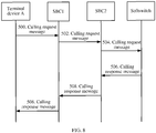
FIG. 8, FIG. 8 is another flowchart of a specific implementation of a method for implementing a session border controller pool according to an embodiment of the present invention. With reference toFIG. 4 , this embodiment is described by using an example in which in Scenario 2, a terminal device initiates a calling service and the terminal device is registered with an SBC2, including: - Step 500: A terminal device A initiates a calling request message, whose destination address is IP11. According to specific routing configuration on a router of an access-side IP bearer network, the calling request message may be sent to any one SBC in an SBC pool, and this embodiment is described by using an example in which the calling request message is sent to an SBC1.
- Step 502: The SBC1 receives the calling request message whose destination address is IP11, and determines that the terminal device A has been registered with the SBC2. The SBC1 forwards the calling request message to the SBC2.
- Step 504: The SBC2 processes the call, and sends the calling request message to a softswitch.
- Step 506: After receiving the calling request message, the softswitch returns a calling response message, whose destination address is IP23.
- Step 508: The SBC2 returns the calling response message to the terminal.
- The calling response message returned by the SBC2 to the terminal device A may be forwarded by the SBC1, and may also be sent to the terminal device A directly. This embodiment is described by using an example in which the calling response message is forwarded by the SBC 1.
- Further, if the SBC2 is faulty, it is required to forward the calling request message to a backup SBC with which the terminal device A is registered. If the backup device of the terminal device A is the SBC1, in
step 502, the SBC1 processes the calling request message directly, and sends the calling request message to the softswitch. A subsequent execution process thereof is similar to that of the SBC2, and no detail is described herein again. If the backup device of the terminal device A is an SBC3, instep 502, the SBC1 forwards the calling request message to the SBC3 for processing. A subsequent execution process thereof is similar to that of the SBC2, and no detail is described herein again. - In the foregoing embodiment, when an SBC1 in the SBC pool receives a calling request message of a terminal device, the SBC1 determines that the terminal device has been registered with an SBC2; and if the terminal device is not registered in the session border controller pool, the SBC1 forwards the calling message to the SBC2, so that the SBC2 processes the calling message. In this way, all SBC devices in the SBC pool can be in a working state, and are mutually backed up for disaster recovery. In addition, a same IP address is configured for a terminal device side, and no special requirement is placed on an existing networking scheme and an existing routing device, so that implementation and popularization are easy.
- Referring to
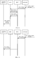
FIG. 9, FIG. 9 is another flowchart of a specific implementation of a method for implementing a session border controller pool according to an embodiment of the present invention. With reference toFIG. 3 , this embodiment is described by using an example in which in Scenario 1, a terminal device is called and the terminal device is registered with an SBC2, including: - Step 600: Another user initiates a calling request message to a terminal device A, and a softswitch receives the calling request message.
- Step 602: After receiving the calling request message, the softswitch delivers the calling request message of the terminal device A to an SBC pool, where a destination address of the calling request message is IP22. According to configuration on a router of a network-side IP bearer network, the calling request message for the terminal device A may be sent to any one SBC in the SBC pool, and this embodiment is described by using an example in which the calling request message is sent to an SBC1.
- Step 604: The SBC1 receives the calling request message whose destination address is IP22, and determines that the terminal device A has been registered with an SBC2. The SBC1 forwards the calling request message to the SBC2.
- Step 606: The SBC2 processes the calling request message, and sends the calling request message to terminal device A.
- The calling request message sent by the SBC2 to the terminal device A may be forwarded by the SBC1, and may also be sent to the terminal device A directly. This embodiment is described by using an example in which the calling request message is forwarded by the SBC1.
- After receiving the calling request message, the terminal device A returns a response message. A subsequent message distributing process is the same as that in the calling process initiated by terminal device A, and no detail is described herein again.
- Further, if the SBC2 is faulty, it is required to forward the calling request message to a backup SBC with which the terminal device A is registered. If the backup device of the terminal device A is the SBC1, in
step 604, the SBC1 processes the calling request message directly, and sends the calling request message to the softswitch. A subsequent execution process thereof is similar to that of the SBC2, and no detail is described herein again. If the backup device of the terminal device A is an SBC3, instep 604, the SBC1 forwards the calling request message to the SBC3 for processing. A subsequent execution process thereof is similar to that of the SBC2, and no detail is described herein again. - In the foregoing embodiment, when an SBC1 in the SBC pool receives a called request message of a terminal device, the SBC1 determines that the terminal device has been registered with an SBC2, and forwards the called request message to the SBC2, so that the SBC2 processes the called request message. In this way, all SBC devices in the SBC pool can be in a working state, and are mutually backed up for disaster recovery. In addition, a same IP address is configured for a terminal device side, a same IP address is also configured for a network side, and no special requirement is placed on an existing networking scheme and an existing routing device, so that implementation and popularization are easy.
- Referring to
FIG. 10, FIG. 10 is another flowchart of a specific implementation of a method for implementing a session border controller pool according to an embodiment of the present invention. With reference toFIG. 4 , this embodiment is described by using an example in which in Scenario 2, a terminal device is called and the terminal device is registered with an SBC2, including: - Step 700: Another user initiates a calling request message to a terminal device A, and a softswitch receives the calling request message.
- Step 702: After receiving the calling request message, the softswitch delivers the calling request message of the terminal device A to an SBC pool, where a destination address of the calling request message is IP23. A routing device of a network-side IP bearer network routes the calling request message to the SBC2 directly.
- Step 704: The SBC2 processes the calling request message, and sends the calling request message to the terminal device A.
- This embodiment is described by using an example in which the SBC2 sends the calling request message to the terminal device A directly.
- After receiving the calling request message, the terminal device A returns a response message. A subsequent message distributing process is the same as that in the calling process initiated by terminal device A, and no detail is described herein again.
- Further, if the SBC2 is faulty, it is required to forward the calling request message to a backup SBC with which the terminal device A is registered. If the backup device of the terminal device A is an SBC1, in
step 702, the destination address of the calling request message, which is delivered by the softswitch, of the terminal device A is IP22, and the SBC1 processes the calling request message directly, and sends the calling request message to the softswitch. A subsequent execution process thereof is similar to that of the SBC2, and no detail is described herein again. If the backup device of the terminal device A is an SBC3, instep 702, the destination address of the calling request message, which is delivered by the softswitch, of the terminal device A is IP24, and the SBC3 processes the calling request message directly. A subsequent execution process thereof is similar to that of the SBC2, and no detail is described herein again. - In the foregoing embodiment, when an SBC2 in the SBC pool receives a called request message of a terminal device, the SBC2 processes the called request message. In this way, all SBC devices in the SBC pool can be in a working state, and are mutually backed up for disaster recovery. In addition, a same IP address is configured for the terminal device, and no special requirement is placed on an existing networking scheme and an existing routing device, so that implementation and popularization are easy.
- Referring to 11,
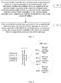
FIG. 11 is a schematic structural diagram of asession border controller 1100 according to an embodiment of the present invention. Thesession border controller 1100 is located in a session border controller pool, the session border controller pool includes the session border controller and one or more other session border controllers, the session border controller and the one or more other session border controllers communicate with a terminal device by using a same IP address, and the session border controller includes areceiving unit 1101 and aforwarding unit 1102, where
thereceiving unit 1101 is configured to receive a service message of the terminal device, and determine whether the terminal device is registered in the session border controller pool; and
theforwarding unit 1102 is configured to: when thereceiving unit 1101 determines that the terminal device has been registered in the session border controller pool, forward the service message to a session border controller with which the terminal device is registered, so that the session border controller with which the terminal device is registered processes the service message. - The service message of the terminal device may be a service message, such as a calling request message or a called request message, of the terminal device. SBC devices in the SBC pool may have different IP addresses in the SBC pool, where the IP addresses are used to distinguish different SBC devices in the SBC pool, so that the SBC devices in the SBC pool can be notified and managed.
- The at least two session border controllers may be disaster-recovery controllers for each other, where the disaster recovery for each other is that the at least two session border controllers are mutually backed up for disaster recovery. Disaster-recovery SBC devices can ensure that a service of the terminal device is not interrupted when an SBC device is faulty. If an SBC device is faulty, another SBC device can replace the faulty SBC device to continue to process the service of the terminal device.
- In the specific implementation manner of the
session border controller 1100 in the foregoing embodiment, it is avoided that disaster recovery of session border controller devices places a special requirement for the terminal device, and the terminal device does not need to be configured with two IP addresses. In addition, all devices in the session border controller pool can process the service message of the terminal device, thereby increasing a resource utilization rate. - Optionally, the
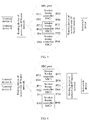
SBC 1100 may further include aregistration unit 1103, as shown inFIG. 12 , and theregistration unit 1103 is configured to: when the terminal device is not registered in the session border controller pool, distribute the service message to any one session border controller in the session border controller pool for registration. - Optionally, the
registration unit 1103 may be further configured to send registration information of the terminal device to another session border controller in the session border controller pool, so that the another session border controller records information of the session border controller with which the terminal device is registered. - The
registration unit 1103 registers the terminal device with any one session border controller in the session border controller pool, which can register an unregistered terminal device in the session border controller pool, and implement disaster recovery backup between session border controllers in the session border controller pool, so that when a session border controller is faulty, the terminal device may also be registered with another session border controller. In addition, theregistration unit 1103 sends the registration information of the terminal device to other session border controller in the session border controller pool, so that the other session border controller in the session border controller pool can know whether the terminal device is registered in the session border controller pool and the session border controller with which the terminal device is registered, and when receiving a service message, for example, a calling request message, of the terminal device, the other session border controller in the session border controller pool can forward the service message of the terminal device to the session border controller with which the terminal device is registered for processing. - Optionally, the
session border controller 1100 and the one or more other session border controllers communicate with a network-side device by using a same IP address; and
the receiving unit is further configured to receive another service message of the network-side device about the terminal device, determine the session border controller with which the terminal device is registered, and forward the another service message to the session border controller with which the terminal device is registered, so that the session border controller with which the terminal device is registered processes the another service message. - The network-side device may be a network control device or another device with a control function, for example, a control device such as a media gateway controller, MGC, or a softswitch.
- The at least two session border controllers communicate with the network-side device by using the same IP address, and no special requirement is placed on a network side, so that implementation manners of the SBCs in the SBC pool can be implemented more easily in an existing network, which can improve the network management quality and efficiency while reducing the maintenance cost.
- Optionally, the determining, by the receiving
unit 1101, whether the terminal device is registered in the session border controller pool includes: - querying a registration list stored by the session border controller and determining whether the registration information of the terminal device is included in the registration list, and if the registration information of the terminal device is not included in the registration list, determining that the terminal device is not registered in the session border controller pool, where the registration list records registration information, which is recorded by the session border controller, of that the terminal device is registered in the session border controller pool.
- Optionally, the
registration unit 1103 includes afirst processing unit 11031 and asecond processing unit 11032, as shown inFIG. 12 , where
thefirst processing unit 11031 is configured to: when the terminal device is not registered in the session border controller pool, distribute the service message to any one session border controller in the session border controller pool for registration; and
thesecond processing unit 11032 is configured to register the terminal device with another session border controller in the session border controller pool, where the another session border controller is a backup device of the any one session border controller, and when the any one session border controller is faulty, the another session border controller processes the service of the terminal device. - Optionally, the distributing, by the
registration unit 1103, the service message to any one session border controller in the session border controller pool for registration includes: - distributing, by the
registration unit 1103 by means of round-robin, random selection, or load balancing, the service message to any one session border controller in the session border controller pool for registration; or - distributing, by the
registration unit 1103, the service message to a session border controller whose physical address is closest to a physical address of the terminal device for registration. - The foregoing implementation manner can further ensure balancing of registration of the terminal device in the SBC pool, and ensure load balancing among devices in the SBC pool.
- For the implementation manner of the
session border controller 1100, reference may be further made to the specific implementation manners of the SBC devices in the SBC pool in the foregoing method embodiments, and no detail is described herein again. - Persons of ordinary skill in the art may be aware that, in combination with the examples described in the embodiments disclosed in this specification, units and steps may be implemented by electronic hardware, computer software, or a combination thereof. To clearly describe the interchangeability between the hardware and the software, the foregoing has generally described compositions and steps of each example according to functions. Whether the functions are performed by hardware or software depends on particular applications and design constraint conditions of the technical solutions. Persons skilled in the art may use different methods to implement the described functions for each particular application, but it should not be considered that the implementation goes beyond the scope of the present invention.
- It may be clearly understood by persons skilled in the art that, for the purpose of convenient and brief description, for a detailed working process of the foregoing apparatus and unit, reference may be made to a corresponding process in the foregoing method embodiments, and details are not described herein again.
- In the several embodiments provided in the present application, it should be understood that the disclosed apparatus and method may be implemented in other manners. For example, the described apparatus embodiment is merely exemplary. For example, the unit division is merely logical function division and may be other division in actual implementation. For example, a plurality of units or components may be combined or integrated into another system, or some features may be ignored or not performed. In addition, the displayed or discussed mutual couplings or direct couplings or communication connections may be implemented through some interfaces. The indirect couplings or communication connections between the apparatuses or units may be implemented in electronic, mechanical, or other forms.
- The units described as separate parts may or may not be physically separate, and parts displayed as units may or may not be physical units, may be located in one position, or may be distributed on a plurality of network units. A part or all of the units may be selected according to actual needs to achieve the objectives of the solutions of the embodiments of the present invention.
- In addition, functional units in the embodiments of the present invention may be integrated into one processing unit, or each of the units may exist alone physically, or two or more units are integrated into one unit. The integrated unit may be implemented in a form of hardware, or may be implemented in a form of a software functional unit.
- When the integrated unit is implemented in the form of a software functional unit and sold or used as an independent product, the integrated unit may be stored in a computer-readable storage medium. Based on such an understanding, the technical solutions of the present invention essentially, or the part contributing to the prior art, or all or a part of the technical solutions may be implemented in the form of a software product. The software product is stored in a storage medium and includes several instructions for instructing a computer device (which may be a personal computer, a server, or a network device) to perform all or a part of the steps of the methods described in the embodiments of the present invention. The foregoing storage medium includes: any medium that can store program code, such as a USB flash drive, a removable hard disk, a read-only memory, ROM, a random access memory, RAM, a magnetic disk, or an optical disc.
- Finally, it should be noted that the foregoing embodiments are merely intended for describing the technical solutions of the present invention rather than limiting the present invention. Although the present invention is described in detail with reference to the foregoing embodiments, persons of ordinary skill in the art should understand that they may still make modifications to the technical solutions recorded in the foregoing embodiments or make equivalent replacements to some technical features thereof, as long as such modifications or replacements do not cause the essence of corresponding technical solutions to depart from the scope of the technical solutions of the embodiments of the present invention.
- Further embodiments of the present invention are provided in the following. It should be noted that the numbering used in the following section does not necessarily need to comply with the numbering used in the previous sections.
- Embodiment 1. A method for implementing a session border controller pool, comprising:
- receiving, by a session border controller in the session border controller pool, a service message of a terminal device, wherein the session border controller pool comprises at least two session border controllers, and the at least two session border controllers in the session border controller pool communicate with the terminal device by using a same IP address;
- determining, by the session border controller receiving the service message of the terminal device, whether the terminal device is registered in the session border controller pool; and
- forwarding, by the session border controller receiving the service message of the terminal device, the service message to a session border controller with which the terminal device is registered if the terminal device has been registered in the session border controller pool, so that the session border controller with which the terminal device is registered processes the service message.
- Embodiment 2. The method for implementing a session border controller pool according to embodiment 1, wherein the method further comprises:
- distributing, by the session border controller receiving the service message of the terminal device, the service message to any one session border controller in the session border controller pool for registration if the terminal device is not registered in the session border controller pool.
- Embodiment 3. The method for implementing a session border controller pool according to embodiment 2, wherein the method further comprises:
- sending, by the session border controller with which the terminal device is registered, registration information of the terminal device to another session border controller in the session border controller pool after the session border controller receiving the service message of the terminal device distributes the service message to the any one session border controller in the session border controller pool for registration, so that the another session border controller records information of the session border controller with which the terminal device is registered.
- Embodiment 4. The method for implementing a session border controller pool according to any one of embodiments 1 to 3, wherein the method further comprises:
- communicating, by the at least two session border controllers comprised in the session border controller pool, with a network-side device by using a same IP address;
- receiving, by a session border controller in the session border controller pool, another service message of the network-side device about the terminal device;
- determining, by the session border controller receiving the another service message of the network-side device, the session border controller with which the terminal device is registered; and
- forwarding, by the session border controller receiving the another service message of the network-side device, the another service message to the session border controller with which the terminal device is registered, so that the session border controller with which the terminal device is registered processes the another service message.
- Embodiment 5. The method for implementing a session border controller pool according to any one of embodiments 1 to 4, wherein the determining whether the terminal device is registered in the session border controller pool comprises:
- querying, by the session border controller receiving the service message of the terminal device, a registration list that is stored by the session border controller receiving the service message of the terminal device and determining whether the registration information of the terminal device is comprised in the registration list, and
- if the registration information of the terminal device is not comprised in the registration list, determining, by the session border controller receiving the service message of the terminal device, that the terminal device is not registered in the session border controller pool, wherein the registration list records information, which is recorded by a session border controller in the session border controller pool, of the session border controller with which the terminal device is registered.
- Embodiment 6. The method for implementing a session border controller pool according to any one of embodiments 2 to 5, wherein after the distributing, by the session border controller receiving the service message of the terminal device, the service message to any one session border controller in the session border controller pool for registration, the method further comprises:
- registering, by the session border controller receiving the service message of the terminal device, the terminal device with another session border controller, wherein the another session border controller is a standby device of the any one session border controller, and when the any one session border controller is faulty, a service of the terminal device is processed by the another session border controller.
- Embodiment 7. The method for implementing a session border controller pool according to any one of embodiments 2 to 6, wherein the distributing, by a session border controller receiving the service message of the terminal device, the service message to the any one session border controller in the session border controller pool for registration comprises:
- distributing, by means of round-robin, random selection, or load balancing, by the session border controller receiving the service message of the terminal device, the service message to the any one session border controller in the session border controller pool for registration; or
- distributing, by the session border controller receiving the service message of the terminal device, the service message to a session border controller whose physical address is closest to a physical address of the terminal device for registration.
- Embodiment 8. A session border controller, wherein the session border controller is located in a session border controller pool, the session border controller pool comprises the session border controller and one or more other session border controllers, and the session border controller and the one or more other session border controllers communicate with a terminal device by using a same IP address;
the session border controller comprises a receiving unit and a forwarding unit; wherein
the receiving unit is configured to receive a service message of the terminal device, and determine whether the terminal device is registered in the session border controller pool; and
the forwarding unit is configured to forward the service message to a session border controller with which the terminal device is registered when the receiving unit determines that the terminal device has been registered in the session border controller pool, so that the session border controller with which the terminal device is registered processes the service message. - Embodiment 9. The session border controller according to embodiment 8, wherein the session border controller further comprises a registration unit; and
the registration unit is configured to distribute the service message to any one session border controller in the session border controller pool for registration when the terminal device is not registered in the session border controller pool. - Embodiment 10. The session border controller according to embodiment 9, wherein the registration unit is further configured to send registration information of the terminal device to other session border controller in the session border controller pool, so that the other session border controller records information of the session border controller with which the terminal device is registered.
- Embodiment 11. The session border controller according to any one of embodiments 8 to 10, wherein the session border controller and the one or more other session border controllers communicate with a network-side device by using a same IP address; and
the receiving unit is further configured to receive another service message of the network-side device about the terminal device, determine the session border controller with which the terminal device is registered, and forward the another service message to the session border controller with which the terminal device is registered, so that the session border controller with which the terminal device is registered processes the another service message. - Embodiment 12. The session border controller according to any one of embodiments 8 to 11, wherein when determining, by the receiving unit, whether the terminal device is registered in the session border controller pool, the receiving unit is specifically configured to query a registration list stored by the session border controller and determine whether the registration information of the terminal device is comprised in the registration list, and if the registration information of the terminal device is not comprised in the registration list, determine that the terminal device is not registered in the session border controller pool, wherein the registration list records information, which is recorded by the session border controller, of the session border controller with which the terminal device is registered.
- Embodiment 13. The session border controller according to any one of embodiments 9 to 12, wherein the registration unit comprises a first processing unit and a second processing unit, wherein
the first processing unit is configured to distribute the service message to any one session border controller in the session border controller pool for registration when the terminal device is not registered in the session border controller pool; and
the second processing unit is configured to register the terminal device with another session border controller in the session border controller pool, wherein the another session border controller is a backup device of the any one session border controller, and when the any one session border controller is faulty, a service of the terminal device is processed by the another session border controller. - Embodiment 14. The session border controller according to any one of embodiments 9 to 12, wherein
the registration unit is specifically configured to distribute by means of round-robin, random selection, or load balancing, the service message to the any one session border controller in the session border controller pool for registration; or distribute the service message to a session border controller whose physical address is closest to a physical address of the terminal device for registration.
Claims (10)
- A method for implementing a session border controller pool, comprising:receiving, by a session border controller pool, a service message send by a terminal device, wherein the session border controller pool comprises at least two session border controllers;determining whether the terminal device is registered in the session border controller pool; anddistributing, by means of loading balance, the service message to any one session border controller in the session border controller pool for registration if the terminal device is not registered in the session border controller pool.
- The method for implementing a session border controller pool according to claim 1, wherein the method further comprises:forwarding the service message to a session border controller with which the terminal device is registered to processes the service message if the terminal device has been registered in the session border controller pool.
- The method for implementing a session border controller pool according to claim 2, wherein the method further comprises:sending, by the any one of session border controller, registration information of the terminal device to another session border controller in the session border controller pool after the terminal device is registered in the any one of session border controller.
- The method for implementing a session border controller pool according to any one of claims 1 to 3, wherein:the at least two session border controllers in the session border controller pool communicate with the terminal device by using a same IP address.
- The method for implementing a session border controller pool according to any one of claims 1 to 4, wherein:the at least two session border controllers comprised in the session border controller pool communicate with a network-side device by using a same IP address.
- The method for implementing a session border controller pool according to any one of claims 1 to 5, wherein the determining whether the terminal device is registered in the session border controller pool comprises:querying a registration list and determining whether the registration information of the terminal device is comprised in the registration list, andif the registration information of the terminal device is not comprised in the registration list, determining, by the session border controller receiving the service message of the terminal device, that the terminal device is not registered in the session border controller pool.
- The method for implementing a session border controller pool according to any one of claims 1 to 6, wherein after the distributing, by means of loading balance, the service message to any one session border controller in the session border controller pool for registration, the method further comprises:registering the terminal device with another session border controller when the any one session border controller is faulty, wherein the another session border controller is a standby device of the any one session border controller.
- A session border controller pool, comprises at least two session border controllers, wherein, the session border controller pool is configured to performing the method according to any one claim of 1-7.
- A computer-readable storage medium comprising instructions which, when executed by a computer, cause the computer to carry out steps of the method according to any one claim of 1-7.
- A computer program product, when executed by a computer, cause the computer to carry out steps of the method according to any one claim of 1-7.
Priority Applications (2)
| Application Number | Priority Date | Filing Date | Title |
|---|---|---|---|
| EP17161743.4A EP3200432B1 (en) | 2011-11-23 | 2011-11-23 | Method for implementing session border controller pool, and session border controller pool |
| ES17161743T ES2700967T3 (en) | 2011-11-23 | 2011-11-23 | Procedure to implement a group of session border controllers, and group of session border controllers |
Applications Claiming Priority (3)
| Application Number | Priority Date | Filing Date | Title |
|---|---|---|---|
| EP11867502.4A EP2773065B1 (en) | 2011-11-23 | 2011-11-23 | Method for enabling session border controller (sbc) pool and sbc |
| PCT/CN2011/082718 WO2012167567A1 (en) | 2011-11-23 | 2011-11-23 | Method for enabling session border controller (sbc) pool and sbc |
| EP17161743.4A EP3200432B1 (en) | 2011-11-23 | 2011-11-23 | Method for implementing session border controller pool, and session border controller pool |
Related Parent Applications (2)
| Application Number | Title | Priority Date | Filing Date |
|---|---|---|---|
| EP11867502.4A Division EP2773065B1 (en) | 2011-11-23 | 2011-11-23 | Method for enabling session border controller (sbc) pool and sbc |
| EP11867502.4A Division-Into EP2773065B1 (en) | 2011-11-23 | 2011-11-23 | Method for enabling session border controller (sbc) pool and sbc |
Publications (2)
| Publication Number | Publication Date |
|---|---|
| EP3200432A1 true EP3200432A1 (en) | 2017-08-02 |
| EP3200432B1 EP3200432B1 (en) | 2018-09-12 |
Family
ID=46222784
Family Applications (2)
| Application Number | Title | Priority Date | Filing Date |
|---|---|---|---|
| EP17161743.4A Active EP3200432B1 (en) | 2011-11-23 | 2011-11-23 | Method for implementing session border controller pool, and session border controller pool |
| EP11867502.4A Active EP2773065B1 (en) | 2011-11-23 | 2011-11-23 | Method for enabling session border controller (sbc) pool and sbc |
Family Applications After (1)
| Application Number | Title | Priority Date | Filing Date |
|---|---|---|---|
| EP11867502.4A Active EP2773065B1 (en) | 2011-11-23 | 2011-11-23 | Method for enabling session border controller (sbc) pool and sbc |
Country Status (5)
| Country | Link |
|---|---|
| US (1) | US9807179B2 (en) |
| EP (2) | EP3200432B1 (en) |
| CN (1) | CN102511146B (en) |
| ES (1) | ES2700967T3 (en) |
| WO (1) | WO2012167567A1 (en) |
Families Citing this family (7)
| Publication number | Priority date | Publication date | Assignee | Title |
|---|---|---|---|---|
| CN103051745A (en) * | 2013-01-21 | 2013-04-17 | 华为技术有限公司 | Obtaining method and device of address of session boundary controller |
| GB2520231B (en) * | 2013-07-23 | 2020-12-16 | Metaswitch Networks Ltd | Media sessions |
| US9781026B2 (en) * | 2015-05-20 | 2017-10-03 | Avaya Inc. | System and method to prevent polling overload for detection of presence information |
| CN106941529A (en) * | 2017-03-21 | 2017-07-11 | 许继电气股份有限公司 | A kind of direct current transportation monitoring system and disaster tolerance implementation method |
| US11695826B2 (en) | 2017-08-14 | 2023-07-04 | Comcast Cable Communications, Llc | Assignment of processing resource based on session data |
| CN111163465B (en) * | 2018-11-07 | 2022-11-08 | 北京京东尚科信息技术有限公司 | Method and device for connecting user terminal and local terminal and call center system |
| US10841344B1 (en) * | 2019-07-15 | 2020-11-17 | Ribbon Communications Operating Company, Inc. | Methods, systems and apparatus for efficient handling of registrations of end devices |
Citations (4)
| Publication number | Priority date | Publication date | Assignee | Title |
|---|---|---|---|---|
| EP1816887A1 (en) * | 2005-08-25 | 2007-08-08 | Huawei Technologies Co., Ltd. | Method and system for improving network reliability by realizing dymanic route of signaling |
| US20080080532A1 (en) * | 2006-09-29 | 2008-04-03 | O'sullivan Mark | Methods and apparatus for managing internet communications using a dynamic STUN infrastructure configuration |
| US20100034079A1 (en) * | 2007-02-06 | 2010-02-11 | France Telecom | Service management in a network |
| WO2010068948A2 (en) * | 2008-12-12 | 2010-06-17 | Tekelec | Methods, systems, and computer readable media for generating and using statelessly reversible representations of session initiation protocol (sip) information by sip cluster entities |
Family Cites Families (9)
| Publication number | Priority date | Publication date | Assignee | Title |
|---|---|---|---|---|
| US7480737B2 (en) * | 2002-10-25 | 2009-01-20 | International Business Machines Corporation | Technique for addressing a cluster of network servers |
| CN100546285C (en) * | 2007-05-09 | 2009-09-30 | 华为技术有限公司 | Realize method, system and the Session Border Controller of Interworking gateway application layer route |
| GB2460651B (en) * | 2008-06-03 | 2012-09-12 | Metaswitch Networks Ltd | Delivery of media data |
| CN101360057B (en) * | 2008-09-02 | 2012-04-04 | 华为终端有限公司 | Route processing method, IMS service processing method and related equipment |
| US8879419B2 (en) * | 2009-07-28 | 2014-11-04 | Centurylink Intellectual Property Llc | System and method for registering an IP telephone |
| CN101998516B (en) * | 2009-08-27 | 2014-03-12 | 中兴通讯股份有限公司 | High-capacity SBC and implementation method thereof |
| US9137163B2 (en) * | 2010-08-04 | 2015-09-15 | Kryterion, Inc. | Optimized data stream upload |
| US8619547B2 (en) * | 2010-11-10 | 2013-12-31 | At&T Intellectual Property I, L.P. | Communication system with failover communication services |
| US8914449B2 (en) * | 2011-11-07 | 2014-12-16 | Cellco Partnership | Push messaging platform with high scalability and high availability |
-
2011
- 2011-11-23 EP EP17161743.4A patent/EP3200432B1/en active Active
- 2011-11-23 EP EP11867502.4A patent/EP2773065B1/en active Active
- 2011-11-23 WO PCT/CN2011/082718 patent/WO2012167567A1/en active Application Filing
- 2011-11-23 ES ES17161743T patent/ES2700967T3/en active Active
- 2011-11-23 CN CN201180002443.9A patent/CN102511146B/en active Active
-
2014
- 2014-05-23 US US14/285,946 patent/US9807179B2/en active Active
Patent Citations (4)
| Publication number | Priority date | Publication date | Assignee | Title |
|---|---|---|---|---|
| EP1816887A1 (en) * | 2005-08-25 | 2007-08-08 | Huawei Technologies Co., Ltd. | Method and system for improving network reliability by realizing dymanic route of signaling |
| US20080080532A1 (en) * | 2006-09-29 | 2008-04-03 | O'sullivan Mark | Methods and apparatus for managing internet communications using a dynamic STUN infrastructure configuration |
| US20100034079A1 (en) * | 2007-02-06 | 2010-02-11 | France Telecom | Service management in a network |
| WO2010068948A2 (en) * | 2008-12-12 | 2010-06-17 | Tekelec | Methods, systems, and computer readable media for generating and using statelessly reversible representations of session initiation protocol (sip) information by sip cluster entities |
Also Published As
| Publication number | Publication date |
|---|---|
| CN102511146B (en) | 2014-06-11 |
| US9807179B2 (en) | 2017-10-31 |
| EP3200432B1 (en) | 2018-09-12 |
| EP2773065B1 (en) | 2017-05-31 |
| ES2700967T3 (en) | 2019-02-20 |
| US20140258551A1 (en) | 2014-09-11 |
| WO2012167567A1 (en) | 2012-12-13 |
| EP2773065A1 (en) | 2014-09-03 |
| EP2773065A4 (en) | 2014-11-05 |
| CN102511146A (en) | 2012-06-20 |
Similar Documents
| Publication | Publication Date | Title |
|---|---|---|
| US9807179B2 (en) | Method for implementing session border controller pool, and session border controller | |
| US9386053B2 (en) | Disaster recovery with a central conferencing routing server | |
| JP5759024B2 (en) | System and method for restoring a session at a geographically redundant gateway | |
| EP2993838B1 (en) | Methods for setting a member identity of gateway device and corresponding management gateway devices | |
| CN107547689B (en) | CGN (Carrier grade network Address translation) method and device | |
| CN101316236B (en) | Vrrp backup group load sharing method and router | |
| US8472311B2 (en) | Systems, methods, and computer readable media for providing instantaneous failover of packet processing elements in a network | |
| US20140115176A1 (en) | Clustered session management | |
| US10367680B2 (en) | Network relay apparatus, gateway redundancy system, program, and redundancy method | |
| WO2018090386A1 (en) | Method, device and system for processing abnormities of nf modules | |
| US10575366B2 (en) | Last resource disaster routing in a telecommunications network | |
| EP2733907B1 (en) | Method, local gateway, and system for local voice survivability | |
| JP5841262B2 (en) | SIP proxy failover method | |
| CA2860509A1 (en) | Central conferencing routing server | |
| CN114585009A (en) | UPF dual-computer hot standby switching method and device, electronic equipment and storage medium | |
| WO2017054535A1 (en) | Traffic forwarding method and apparatus | |
| JP2023543428A (en) | Methods, systems and computer-readable media for distributing S1 connections to a mobility management entity (MME) and N2 connections to an access and mobility management function (AMF) | |
| JP5545887B2 (en) | Distributed recovery method and network system | |
| JP5541477B2 (en) | Voice communication system and terminal registration method | |
| US9019964B2 (en) | Methods and systems for routing application traffic | |
| EP3843342A1 (en) | Communication method and related device | |
| KR102168583B1 (en) | Load balancing management apparatus and control method thereof |
Legal Events
| Date | Code | Title | Description |
|---|---|---|---|
| PUAI | Public reference made under article 153(3) epc to a published international application that has entered the european phase |
Free format text: ORIGINAL CODE: 0009012 |
|
| AC | Divisional application: reference to earlier application |
Ref document number: 2773065 Country of ref document: EP Kind code of ref document: P |
|
| AK | Designated contracting states |
Kind code of ref document: A1 Designated state(s): AL AT BE BG CH CY CZ DE DK EE ES FI FR GB GR HR HU IE IS IT LI LT LU LV MC MK MT NL NO PL PT RO RS SE SI SK SM TR |
|
| REG | Reference to a national code |
Ref country code: DE Ref legal event code: R079 Ref document number: 602011052110 Country of ref document: DE Free format text: PREVIOUS MAIN CLASS: H04L0029080000 Ipc: H04L0029060000 |
|
| 17P | Request for examination filed |
Effective date: 20180131 |
|
| RBV | Designated contracting states (corrected) |
Designated state(s): AL AT BE BG CH CY CZ DE DK EE ES FI FR GB GR HR HU IE IS IT LI LT LU LV MC MK MT NL NO PL PT RO RS SE SI SK SM TR |
|
| GRAP | Despatch of communication of intention to grant a patent |
Free format text: ORIGINAL CODE: EPIDOSNIGR1 |
|
| RIC1 | Information provided on ipc code assigned before grant |
Ipc: H04L 29/14 20060101ALI20180228BHEP Ipc: H04L 29/08 20060101ALI20180228BHEP Ipc: H04L 29/06 20060101AFI20180228BHEP |
|
| INTG | Intention to grant announced |
Effective date: 20180316 |
|
| GRAS | Grant fee paid |
Free format text: ORIGINAL CODE: EPIDOSNIGR3 |
|
| GRAA | (expected) grant |
Free format text: ORIGINAL CODE: 0009210 |
|
| AC | Divisional application: reference to earlier application |
Ref document number: 2773065 Country of ref document: EP Kind code of ref document: P |
|
| AK | Designated contracting states |
Kind code of ref document: B1 Designated state(s): AL AT BE BG CH CY CZ DE DK EE ES FI FR GB GR HR HU IE IS IT LI LT LU LV MC MK MT NL NO PL PT RO RS SE SI SK SM TR |
|
| REG | Reference to a national code |
Ref country code: GB Ref legal event code: FG4D |
|
| REG | Reference to a national code |
Ref country code: CH Ref legal event code: EP |
|
| REG | Reference to a national code |
Ref country code: IE Ref legal event code: FG4D |
|
| REG | Reference to a national code |
Ref country code: DE Ref legal event code: R096 Ref document number: 602011052110 Country of ref document: DE Ref country code: FR Ref legal event code: PLFP Year of fee payment: 8 |
|
| REG | Reference to a national code |
Ref country code: AT Ref legal event code: REF Ref document number: 1041930 Country of ref document: AT Kind code of ref document: T Effective date: 20181015 |
|
| REG | Reference to a national code |
Ref country code: NL Ref legal event code: FP |
|
| REG | Reference to a national code |
Ref country code: SE Ref legal event code: TRGR |
|
| REG | Reference to a national code |
Ref country code: LT Ref legal event code: MG4D |
|
| PG25 | Lapsed in a contracting state [announced via postgrant information from national office to epo] |
Ref country code: LT Free format text: LAPSE BECAUSE OF FAILURE TO SUBMIT A TRANSLATION OF THE DESCRIPTION OR TO PAY THE FEE WITHIN THE PRESCRIBED TIME-LIMIT Effective date: 20180912 Ref country code: RS Free format text: LAPSE BECAUSE OF FAILURE TO SUBMIT A TRANSLATION OF THE DESCRIPTION OR TO PAY THE FEE WITHIN THE PRESCRIBED TIME-LIMIT Effective date: 20180912 Ref country code: GR Free format text: LAPSE BECAUSE OF FAILURE TO SUBMIT A TRANSLATION OF THE DESCRIPTION OR TO PAY THE FEE WITHIN THE PRESCRIBED TIME-LIMIT Effective date: 20181213 Ref country code: NO Free format text: LAPSE BECAUSE OF FAILURE TO SUBMIT A TRANSLATION OF THE DESCRIPTION OR TO PAY THE FEE WITHIN THE PRESCRIBED TIME-LIMIT Effective date: 20181212 Ref country code: BG Free format text: LAPSE BECAUSE OF FAILURE TO SUBMIT A TRANSLATION OF THE DESCRIPTION OR TO PAY THE FEE WITHIN THE PRESCRIBED TIME-LIMIT Effective date: 20181212 |
|
| REG | Reference to a national code |
Ref country code: ES Ref legal event code: FG2A Ref document number: 2700967 Country of ref document: ES Kind code of ref document: T3 Effective date: 20190220 |
|
| PG25 | Lapsed in a contracting state [announced via postgrant information from national office to epo] |
Ref country code: LV Free format text: LAPSE BECAUSE OF FAILURE TO SUBMIT A TRANSLATION OF THE DESCRIPTION OR TO PAY THE FEE WITHIN THE PRESCRIBED TIME-LIMIT Effective date: 20180912 Ref country code: AL Free format text: LAPSE BECAUSE OF FAILURE TO SUBMIT A TRANSLATION OF THE DESCRIPTION OR TO PAY THE FEE WITHIN THE PRESCRIBED TIME-LIMIT Effective date: 20180912 Ref country code: HR Free format text: LAPSE BECAUSE OF FAILURE TO SUBMIT A TRANSLATION OF THE DESCRIPTION OR TO PAY THE FEE WITHIN THE PRESCRIBED TIME-LIMIT Effective date: 20180912 |
|
| REG | Reference to a national code |
Ref country code: AT Ref legal event code: MK05 Ref document number: 1041930 Country of ref document: AT Kind code of ref document: T Effective date: 20180912 |
|
| PG25 | Lapsed in a contracting state [announced via postgrant information from national office to epo] |
Ref country code: IS Free format text: LAPSE BECAUSE OF FAILURE TO SUBMIT A TRANSLATION OF THE DESCRIPTION OR TO PAY THE FEE WITHIN THE PRESCRIBED TIME-LIMIT Effective date: 20190112 Ref country code: EE Free format text: LAPSE BECAUSE OF FAILURE TO SUBMIT A TRANSLATION OF THE DESCRIPTION OR TO PAY THE FEE WITHIN THE PRESCRIBED TIME-LIMIT Effective date: 20180912 Ref country code: AT Free format text: LAPSE BECAUSE OF FAILURE TO SUBMIT A TRANSLATION OF THE DESCRIPTION OR TO PAY THE FEE WITHIN THE PRESCRIBED TIME-LIMIT Effective date: 20180912 Ref country code: PL Free format text: LAPSE BECAUSE OF FAILURE TO SUBMIT A TRANSLATION OF THE DESCRIPTION OR TO PAY THE FEE WITHIN THE PRESCRIBED TIME-LIMIT Effective date: 20180912 Ref country code: RO Free format text: LAPSE BECAUSE OF FAILURE TO SUBMIT A TRANSLATION OF THE DESCRIPTION OR TO PAY THE FEE WITHIN THE PRESCRIBED TIME-LIMIT Effective date: 20180912 Ref country code: CZ Free format text: LAPSE BECAUSE OF FAILURE TO SUBMIT A TRANSLATION OF THE DESCRIPTION OR TO PAY THE FEE WITHIN THE PRESCRIBED TIME-LIMIT Effective date: 20180912 |
|
| PG25 | Lapsed in a contracting state [announced via postgrant information from national office to epo] |
Ref country code: SM Free format text: LAPSE BECAUSE OF FAILURE TO SUBMIT A TRANSLATION OF THE DESCRIPTION OR TO PAY THE FEE WITHIN THE PRESCRIBED TIME-LIMIT Effective date: 20180912 Ref country code: PT Free format text: LAPSE BECAUSE OF FAILURE TO SUBMIT A TRANSLATION OF THE DESCRIPTION OR TO PAY THE FEE WITHIN THE PRESCRIBED TIME-LIMIT Effective date: 20190112 Ref country code: SK Free format text: LAPSE BECAUSE OF FAILURE TO SUBMIT A TRANSLATION OF THE DESCRIPTION OR TO PAY THE FEE WITHIN THE PRESCRIBED TIME-LIMIT Effective date: 20180912 |
|
| REG | Reference to a national code |
Ref country code: DE Ref legal event code: R097 Ref document number: 602011052110 Country of ref document: DE |
|
| PLBE | No opposition filed within time limit |
Free format text: ORIGINAL CODE: 0009261 |
|
| STAA | Information on the status of an ep patent application or granted ep patent |
Free format text: STATUS: NO OPPOSITION FILED WITHIN TIME LIMIT |
|
| PG25 | Lapsed in a contracting state [announced via postgrant information from national office to epo] |
Ref country code: DK Free format text: LAPSE BECAUSE OF FAILURE TO SUBMIT A TRANSLATION OF THE DESCRIPTION OR TO PAY THE FEE WITHIN THE PRESCRIBED TIME-LIMIT Effective date: 20180912 Ref country code: LU Free format text: LAPSE BECAUSE OF NON-PAYMENT OF DUE FEES Effective date: 20181123 Ref country code: MC Free format text: LAPSE BECAUSE OF FAILURE TO SUBMIT A TRANSLATION OF THE DESCRIPTION OR TO PAY THE FEE WITHIN THE PRESCRIBED TIME-LIMIT Effective date: 20180912 |
|
| REG | Reference to a national code |
Ref country code: BE Ref legal event code: MM Effective date: 20181130 |
|
| 26N | No opposition filed |
Effective date: 20190613 |
|
| REG | Reference to a national code |
Ref country code: IE Ref legal event code: MM4A |
|
| PG25 | Lapsed in a contracting state [announced via postgrant information from national office to epo] |
Ref country code: SI Free format text: LAPSE BECAUSE OF FAILURE TO SUBMIT A TRANSLATION OF THE DESCRIPTION OR TO PAY THE FEE WITHIN THE PRESCRIBED TIME-LIMIT Effective date: 20180912 |
|
| PG25 | Lapsed in a contracting state [announced via postgrant information from national office to epo] |
Ref country code: IE Free format text: LAPSE BECAUSE OF NON-PAYMENT OF DUE FEES Effective date: 20181123 |
|
| PG25 | Lapsed in a contracting state [announced via postgrant information from national office to epo] |
Ref country code: BE Free format text: LAPSE BECAUSE OF NON-PAYMENT OF DUE FEES Effective date: 20181130 |
|
| PG25 | Lapsed in a contracting state [announced via postgrant information from national office to epo] |
Ref country code: MT Free format text: LAPSE BECAUSE OF NON-PAYMENT OF DUE FEES Effective date: 20181123 |
|
| PG25 | Lapsed in a contracting state [announced via postgrant information from national office to epo] |
Ref country code: TR Free format text: LAPSE BECAUSE OF FAILURE TO SUBMIT A TRANSLATION OF THE DESCRIPTION OR TO PAY THE FEE WITHIN THE PRESCRIBED TIME-LIMIT Effective date: 20180912 |
|
| PG25 | Lapsed in a contracting state [announced via postgrant information from national office to epo] |
Ref country code: CY Free format text: LAPSE BECAUSE OF FAILURE TO SUBMIT A TRANSLATION OF THE DESCRIPTION OR TO PAY THE FEE WITHIN THE PRESCRIBED TIME-LIMIT Effective date: 20180912 Ref country code: MK Free format text: LAPSE BECAUSE OF NON-PAYMENT OF DUE FEES Effective date: 20180912 Ref country code: HU Free format text: LAPSE BECAUSE OF FAILURE TO SUBMIT A TRANSLATION OF THE DESCRIPTION OR TO PAY THE FEE WITHIN THE PRESCRIBED TIME-LIMIT; INVALID AB INITIO Effective date: 20111123 |
|
| REG | Reference to a national code |
Ref country code: DE Ref legal event code: R079 Ref document number: 602011052110 Country of ref document: DE Free format text: PREVIOUS MAIN CLASS: H04L0029060000 Ipc: H04L0065000000 |
|
| P01 | Opt-out of the competence of the unified patent court (upc) registered |
Effective date: 20230524 |
|
| PGFP | Annual fee paid to national office [announced via postgrant information from national office to epo] |
Ref country code: NL Payment date: 20231013 Year of fee payment: 13 Ref country code: FR Payment date: 20230929 Year of fee payment: 13 |
|
| PGFP | Annual fee paid to national office [announced via postgrant information from national office to epo] |
Ref country code: GB Payment date: 20231006 Year of fee payment: 13 |
|
| PGFP | Annual fee paid to national office [announced via postgrant information from national office to epo] |
Ref country code: ES Payment date: 20231207 Year of fee payment: 13 |
|
| PGFP | Annual fee paid to national office [announced via postgrant information from national office to epo] |
Ref country code: SE Payment date: 20231002 Year of fee payment: 13 Ref country code: IT Payment date: 20231010 Year of fee payment: 13 Ref country code: CH Payment date: 20231201 Year of fee payment: 13 Ref country code: FI Payment date: 20231116 Year of fee payment: 13 Ref country code: DE Payment date: 20230929 Year of fee payment: 13 |