EP3200026A1 - Image forming apparatus and image forming method - Google Patents
Image forming apparatus and image forming method Download PDFInfo
- Publication number
- EP3200026A1 EP3200026A1 EP17150408.7A EP17150408A EP3200026A1 EP 3200026 A1 EP3200026 A1 EP 3200026A1 EP 17150408 A EP17150408 A EP 17150408A EP 3200026 A1 EP3200026 A1 EP 3200026A1
- Authority
- EP
- European Patent Office
- Prior art keywords
- transfer
- image
- transfer bias
- belt
- toner
- Prior art date
- Legal status (The legal status is an assumption and is not a legal conclusion. Google has not performed a legal analysis and makes no representation as to the accuracy of the status listed.)
- Granted
Links
Images


Classifications
-
- G—PHYSICS
- G03—PHOTOGRAPHY; CINEMATOGRAPHY; ANALOGOUS TECHNIQUES USING WAVES OTHER THAN OPTICAL WAVES; ELECTROGRAPHY; HOLOGRAPHY
- G03G—ELECTROGRAPHY; ELECTROPHOTOGRAPHY; MAGNETOGRAPHY
- G03G15/00—Apparatus for electrographic processes using a charge pattern
- G03G15/01—Apparatus for electrographic processes using a charge pattern for producing multicoloured copies
-
- G—PHYSICS
- G03—PHOTOGRAPHY; CINEMATOGRAPHY; ANALOGOUS TECHNIQUES USING WAVES OTHER THAN OPTICAL WAVES; ELECTROGRAPHY; HOLOGRAPHY
- G03G—ELECTROGRAPHY; ELECTROPHOTOGRAPHY; MAGNETOGRAPHY
- G03G13/00—Electrographic processes using a charge pattern
- G03G13/34—Editing, i.e. producing a composite image by copying one or more original images or parts thereof
-
- G—PHYSICS
- G03—PHOTOGRAPHY; CINEMATOGRAPHY; ANALOGOUS TECHNIQUES USING WAVES OTHER THAN OPTICAL WAVES; ELECTROGRAPHY; HOLOGRAPHY
- G03G—ELECTROGRAPHY; ELECTROPHOTOGRAPHY; MAGNETOGRAPHY
- G03G15/00—Apparatus for electrographic processes using a charge pattern
- G03G15/01—Apparatus for electrographic processes using a charge pattern for producing multicoloured copies
- G03G15/0142—Structure of complete machines
- G03G15/0178—Structure of complete machines using more than one reusable electrographic recording member, e.g. one for every monocolour image
- G03G15/0189—Structure of complete machines using more than one reusable electrographic recording member, e.g. one for every monocolour image primary transfer to an intermediate transfer belt
-
- G—PHYSICS
- G03—PHOTOGRAPHY; CINEMATOGRAPHY; ANALOGOUS TECHNIQUES USING WAVES OTHER THAN OPTICAL WAVES; ELECTROGRAPHY; HOLOGRAPHY
- G03G—ELECTROGRAPHY; ELECTROPHOTOGRAPHY; MAGNETOGRAPHY
- G03G15/00—Apparatus for electrographic processes using a charge pattern
- G03G15/14—Apparatus for electrographic processes using a charge pattern for transferring a pattern to a second base
-
- G—PHYSICS
- G03—PHOTOGRAPHY; CINEMATOGRAPHY; ANALOGOUS TECHNIQUES USING WAVES OTHER THAN OPTICAL WAVES; ELECTROGRAPHY; HOLOGRAPHY
- G03G—ELECTROGRAPHY; ELECTROPHOTOGRAPHY; MAGNETOGRAPHY
- G03G15/00—Apparatus for electrographic processes using a charge pattern
- G03G15/14—Apparatus for electrographic processes using a charge pattern for transferring a pattern to a second base
- G03G15/16—Apparatus for electrographic processes using a charge pattern for transferring a pattern to a second base of a toner pattern, e.g. a powder pattern, e.g. magnetic transfer
- G03G15/1605—Apparatus for electrographic processes using a charge pattern for transferring a pattern to a second base of a toner pattern, e.g. a powder pattern, e.g. magnetic transfer using at least one intermediate support
-
- G—PHYSICS
- G03—PHOTOGRAPHY; CINEMATOGRAPHY; ANALOGOUS TECHNIQUES USING WAVES OTHER THAN OPTICAL WAVES; ELECTROGRAPHY; HOLOGRAPHY
- G03G—ELECTROGRAPHY; ELECTROPHOTOGRAPHY; MAGNETOGRAPHY
- G03G15/00—Apparatus for electrographic processes using a charge pattern
- G03G15/14—Apparatus for electrographic processes using a charge pattern for transferring a pattern to a second base
- G03G15/16—Apparatus for electrographic processes using a charge pattern for transferring a pattern to a second base of a toner pattern, e.g. a powder pattern, e.g. magnetic transfer
- G03G15/1665—Apparatus for electrographic processes using a charge pattern for transferring a pattern to a second base of a toner pattern, e.g. a powder pattern, e.g. magnetic transfer by introducing the second base in the nip formed by the recording member and at least one transfer member, e.g. in combination with bias or heat
- G03G15/167—Apparatus for electrographic processes using a charge pattern for transferring a pattern to a second base of a toner pattern, e.g. a powder pattern, e.g. magnetic transfer by introducing the second base in the nip formed by the recording member and at least one transfer member, e.g. in combination with bias or heat at least one of the recording member or the transfer member being rotatable during the transfer
- G03G15/1675—Apparatus for electrographic processes using a charge pattern for transferring a pattern to a second base of a toner pattern, e.g. a powder pattern, e.g. magnetic transfer by introducing the second base in the nip formed by the recording member and at least one transfer member, e.g. in combination with bias or heat at least one of the recording member or the transfer member being rotatable during the transfer with means for controlling the bias applied in the transfer nip
Definitions
- Embodiments of the present invention generally relate to an image forming apparatus, such as a copier, a printer, a facsimile machine, or a multifunction peripheral having at least two of copying, printing, facsimile transmission, plotting, and scanning capabilities, and an image formation method.
- an image forming apparatus such as a copier, a printer, a facsimile machine, or a multifunction peripheral having at least two of copying, printing, facsimile transmission, plotting, and scanning capabilities, and an image formation method.
- Patent Document 1 an image forming apparatus described in JP-2006-195143-A1 (hereinafter "Patent Document 1”) includes an endless intermediate transfer belt that moves while sequentially contacting multiple photoconductors serving as image bearers, and the contact positions with the photoconductors are called primary transfer nips.
- the image forming apparatus further includes multiple primary-transfer bias rollers. A transfer bias is applied to each of the primary-transfer bias rollers in a state in which the primary-transfer bias roller sandwiches the intermediate transfer belt together with the corresponding one of the photoconductors. In each of the primary transfer nips, the toner image is primarily transferred from the photoconductor and superimposed one on another on the intermediate transfer belt.
- the superimposed image is transferred from the intermediate transfer belt onto a recording sheet (i.e., a recording medium) nipped in the secondary transfer nip.
- a recording sheet i.e., a recording medium
- the image forming apparatus described in Patent Document 1 uses, as the intermediate transfer belt, a single-layer belt including polyimide (PI) as a main component and having a thickness of 100 ⁇ m.
- the image forming apparatus described in Patent Document 1 employs direct transfer-bias application, in which the transfer roller contacts a back side of the belt the contact position between the photoconductor and the belt.
- the belt made of polyimide can be a long-life belt with elongation of the belt inhibited.
- the intermediate transfer belt is made of a material having a relatively high rigidity, however, cohesion between the intermediate transfer belt and the photoconductor is lower, and efficiency in primary transfer of toner images is degraded. Additionally, it is difficult to secondarily transfer toner images onto recording sheets having a lower surface smoothness.
- Patent Document 1 states that the volume resistivity of the intermediate transfer belt is from 10 8 to 10 12 ⁇ cm.
- the intermediate transfer belt is multilayered and includes a flexible layer to tightly contact the photoconductors and a rigid layer to restrict elongation of the belt.
- the inventors have found that use of a multilayered intermediate transfer belt increases the possibility of uneven image density and recognize there is a need for balancing desirable efficiency in transferring, long life of a transfer belt, and inhibition of uneven image density.
- the image forming apparatus includes a plurality of image bearers; a plurality of image forming devices to form toner images on the plurality of image bearers, respectively; an endless belt including a plurality of layers and disposed in contact with the plurality of image bearers to form transfer nips; and a plurality of transfer bias members.
- a transfer bias is applied to each of the transfer bias members in a state in which the transfer bias member sandwiches the endless belt together with one of the plurality of image bearers to transfer a toner image from the one of the plurality of image bearers onto a surface of the endless belt or a recording medium conveyed by the endless belt in each of the transfer nips.
- a downstream transfer bias member which is located extreme downstream in a sequence of transfer process, is lower in electrical resistance than an upstream transfer bias member, which is located extreme upstream in the sequence of transfer process.
- the image forming method includes a step of endlessly moving an endless belt to sequentially contact a plurality of image bearers to form a transfer nip at each contact position with one of the plurality of image bearers; a step of applying a transfer bias to each of a plurality of transfer bias members, each of which sandwiching the endless belt together with one of the plurality of image bearers; a step of forming a toner image on at least one of the plurality of image bearers; and a step of transferring, in the transfer nip, the toner image from at least one of the plurality of image bearers onto either a surface of the endless belt or a recording medium carried on the endless belt.
- the endless belt is multilayered.
- a downstream transfer bias member which is located extreme downstream in a sequence of transfer process, is lower in electrical resistance than an upstream transfer bias member, which is located extreme upstream in the sequence of transfer process.
- FIG. 1 an image forming apparatus according to an embodiment of the present invention is described.
- the singular forms “a”, “an”, and “the” are intended to include the plural forms as well, unless the context clearly indicates otherwise.
- the image forming apparatus is a printer employing a tandem system and an intermediate transfer.
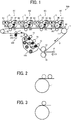
- FIG. 1 is a schematic diagram illustrating an image forming apparatus 500 according to the present embodiment.
- the image forming apparatus 500 includes four process units 6Y, 6C, 6M, and 6K (also collectively “process units 6") for forming yellow, cyan, magenta, and black toner images.
- the process units 6Y, 6C, 6M, and 6K include drum-shaped photoconductors 1Y, 1M, 1C, and 1K (also collectively "photoconductors 1") serving as image bearers, respectively.
- a charging device 2 (2Y, 2M, 2C, or 2K)
- a developing device 5 (5Y, 5M, 5C, or 5K)
- a drum cleaner 4 (4Y, 4M, 4C, or 4K) and a discharger are disposed.
- the process units 6Y, 6M, 6C, and 6K are similar in configuration except that the color of toner used therein is different.
- optical writing unit irradiates the surfaces of the photoconductors 1 with laser beams L to optically write electrostatic latent images thereon.
- the transfer unit 7 includes an endless intermediate transfer belt 8 and a plurality of tension rollers disposed inside the loop of the intermediate transfer belt 8. Outside the loop, the transfer unit 7 further includes a secondary transfer roller 18, a tension roller 16, a belt cleaner 100, and a lubrication device 200.
- primary transfer rollers 9Y, 9M, 9C, and 9K Disposed inside the loop of the intermediate transfer belt 8 are four primary transfer rollers 9Y, 9M, 9C, and 9K (collectively “primary transfer rollers 9"), a driven roller 10, a driving roller 11, a secondary-transfer backup roller 12, three cleaning-backup rollers 13, 14, and 15, and a brush-opposing roller 17.
- a portion of the intermediate transfer belt 8 is entrained around each of these rollers, and these rollers serves as the tension rollers to keep the intermediate transfer belt 8 taut. It is not necessary that the cleaning-backup rollers 13, 14, and 15 function as the tension rollers to give a certain tension to the intermediate transfer belt 8 as long as the cleaning-backup rollers 13, 14, and 15 rotate as the intermediate transfer belt 8 rotates.
- the driving roller 11 rotates counterclockwise (i.e., the belt travel direction) in the drawing, driven by a driver, the intermediate transfer belt 8 rotates (that is, the surface thereof moves endlessly) counterclockwise in the drawing.
- a power supply apples a transfer bias, which is opposite in polarity from the toner.
- the intermediate transfer belt 8 is nipped between the secondary-transfer backup roller 12 disposed inside the looped intermediate transfer belt 8 and the secondary transfer roller 18 disposed outside the looped intermediate transfer belt 8.
- the outer face (front side) of the intermediate transfer belt 8 contacts the secondary transfer roller 18, and the contact portion therebetween serves as a secondary transfer nip.
- a power supply applies a secondary transfer bias, which is identical in polarity to the normal charge polarity of toner.
- a sheet conveyor belt is entrained around the secondary transfer roller 18, several support rollers, and a driving roller. The intermediate transfer belt 8 and the sheet conveyor belt are nipped between the secondary transfer roller 18 and the secondary-transfer backup roller 12.
- the intermediate transfer belt 8 is nipped between the cleaning-backup rollers 13, 14, and 15 disposed inside the looped intermediate transfer belt 8 and three cleaning brush rollers of the belt cleaner 100, disposed outside the looped intermediate transfer belt 8.
- the portions where the outer face of the intermediate transfer belt 8 contacts the three cleaning brush rollers serve as cleaning nips.
- the belt cleaner 100 is united with the transfer unit 7 and replaceable together with the transfer unit 7.
- the belt cleaner 100 is removable therefrom.
- the belt cleaner 100 includes a subunit. The subunit is mountable in and removable from the belt cleaner 100 in a state in which the transfer unit 7 and the belt cleaner 100 are mounted in the apparatus body. The belt cleaner 100 is described in further detail later.
- the image forming apparatus 500 includes a sheet feeder that includes a sheet tray to contain recording sheets P, a sheet feeding roller to feed the sheet P from the sheet tray to a sheet feeding path, and the like. Further, a registration roller pair is disposed on the right of the secondary transfer nip in the drawing. The registration roller pair receives the recording sheet P fed from the sheet feeder and timely forwards the recording sheet P to the secondary transfer nip. On the left of the secondary transfer nip in the drawing, a fixing device is disposed. The fixing device receives the recording sheet P released from the secondary transfer nip and fixes an image on the recording sheet P. Further, toner supply devices to supply, as required, yellow, magenta, cyan, and black toners to the developing devices 5Y, 5M, 5C, and 5K, respectively, are provided.
- the image forming apparatus 500 drives the driving roller 11, thereby rotating the intermediate transfer belt 8.
- the tension rollers other than the driving roller 11 are driven to rotate as the intermediate transfer belt 8 rotates.
- the respective photoconductors 1 of the process units 6 are rotated.
- the charging device 2 uniformly charges the surface of the photoconductor 1
- the charged surface is irradiated with the laser beam L to form an electrostatic latent image thereon.
- the developing device 5 develops the electrostatic latent image on the photoconductor 1.
- yellow, magenta, cyan, and black toner images are formed on the photoconductors 1Y, 1M, 1C, and 1K, respectively.
- the yellow, magenta, cyan, and black toner images are transferred and superimposed one on another on the intermediate transfer belt 8.
- a four-color superimposed toner image is formed on the outer face of the intermediate transfer belt 8.
- the sheet feeding roller feds the recording sheets P from the sheet tray one by one to the registration roller pair.
- the registration roller pair is driven to feed the recording sheet P to the secondary transfer nip, timed to coincide with the four-color toner image on the intermediate transfer belt 8.
- the four-color toner image is secondarily transferred at a time onto the recording sheet P.
- a full-color toner image is formed on the recording sheet P.
- the recording sheet P is transported from the secondary transfer nip to the fixing device, where the toner image is fixed on the recording sheet P.
- the drum cleaners 4Y, 4M, 4C, and 4K remove toner remaining on the photoconductors 1Y, 1M, 1C, and 1K, respectively. Further, discharge lamps removes residual potentials from the photoconductors 1Y, 1M, 1C, and 1K, and the charging devices 2Y, 2M, 2C, and 2K uniformly charge the photoconductors 1Y, 1M, 1C, and 1K, respectively, as preparation for subsequent image formation.
- the belt cleaner 100 removes toner remaining on the intermediate transfer belt 8 after the toner image is secondarily transferred onto the recording sheet P.
- an optical sensor unit 90 is disposed on the right of the process unit 6K for black in FIG. 1 .
- the optical sensor unit 90 faces, across a predetermined gap, the outer face of the intermediate transfer belt 8.
- the optical sensor unit 90 emits light from a light-emitting element, reflects the light on either the outer face of the intermediate transfer belt 8 or the toner image on the intermediate transfer belt 8, and detects the level of reflected light with a light-receiving element.
- a controller e.g., a controller 900 in FIG. 9
- the surface of the intermediate transfer belt 8 is lubricated by the lubrication device 200 for protection.
- the lubrication device 200 includes a solid lubricant 202, such as a block of zinc stearate, and an application brush roller 201 to contact the solid lubricant 202. While rotating, the application brush roller 201 applies powdered lubricant, which is scraped off from the solid lubricant 202, onto the surface of the intermediate transfer belt 8.
- the image forming apparatus 500 includes the lubrication device 200, lubrication of the intermediate transfer belt 8 may be unnecessary depending on the type of toner, the material of the intermediate transfer belt 8, the surface friction coefficient of the intermediate transfer belt 8, and the like.
- the transfer bias In applying the transfer bias to transfer a toner image in the contact portion between the belt and the photoconductor, there are two transfer types, namely, indirect transfer-bias application and direct transfer-bias application.
- indirect transfer-bias application as illustrated in FIG. 2 , a transfer roller contacts a back side of the belt at a position shifted from the contact position between the photoconductor and the belt.
- the electrical charges transferred from the transfer roller to the belt are caused to flow, along the loop of the belt, to the primary transfer nip. Accordingly, the electrical resistance of the belt is preferably relatively low.
- a metal roller having a very small electrical resistance can be used.
- the belt is nipped between the transfer roller and the photoconductor 1, thus forming the transfer nip.
- the intermediate transfer belt is a single layer belt and direct transfer-bias application is employed
- a primary transfer roller made of metal is used, severe electrical discharge may occur between the photoconductor 1 and the primary transfer roller. Accordingly, use of a primary transfer roller made of metal is not preferred. It is preferred to use, as the primary transfer roller, a roller having a certain level of electrical resistance, such as a sponge roller or a rubber roller.
- the volume resistivity of the primary transfer roller is about 6 to 8 Log ( ⁇ cm), and a range of from 6.5 to 7.5 Log ( ⁇ cm) is preferred.
- the voltage value of the primary transfer bias can significantly fluctuate under constant-current control, depending on, for example, the charging potential of the photoconductor 1 and the area of image writing. Then, stabilizing image quality becomes difficult.
- belt back side In indirect transfer-bias application, it is necessary that the resistance of the back side of the belt (hereinafter “belt back side”) is lower compared with direct transfer-bias application.
- belt back side In indirect transfer-bias application, it is necessary that the resistance of the back side of the belt (hereinafter “belt back side”) is lower compared with direct transfer-bias application.
- desirable transfer efficiency is attained when the resistance of the belt back side is from 11 to 12 Log ohms per square ( ⁇ / ⁇ ).
- desirable transfer efficiency is attained when the resistance of the belt back side is from 9 to 10 Log ⁇ / ⁇ .
- the transfer bias In indirect transfer-bias application, the transfer bias is easily transmitted in the direction of loop of the belt and easily escapes from a ground roller. Thus, power saving efficiency is not good.
- the intermediate transfer belt 8 is multilayered and includes at least a base layer 81 (i.e., a belt base) made of a material having a relatively high rigidity and one layer superimposed on the front side of the base layer 81 as illustrated in FIG. 10 .
- a base layer 81 i.e., a belt base
- an elastic layer 82 made of a material that excels in elasticity is superimposed.
- the intermediate transfer belt 8 can tightly contact the photoconductor 1 in the primary transfer nip. Then, desirable efficiency is attained in primary transfer of toner images.
- the intermediate transfer belt 8 can conform to subtle surface unevenness of the recording sheet in the secondary transfer nip. Then, desirable efficiency is attained in secondary transfer of toner images even when the recording sheet has a low smoothness.
- the base layer 81 made of a material, such as polyimide, having a relatively high rigidity, can inhibit elongation of the belt over time, thereby extending the useful life of the intermediate transfer belt 8.
- the intermediate transfer belt 8 preferably includes a coating layer (i.e., a surface layer) made of a material having a better capability to release toner than the elastic layer 82.
- Elastic materials usable for the elastic layer 82 of the intermediate transfer belt 8 include elastic rubber and elastomer.
- example elastic materials include, but are not limited to, butyl rubber, fluorine-based rubber, acrylic rubber, ethylene-propylene-diene monomer (EPDM), nitrile butadiene rubber, acrylonitrile-butadiene-styrene rubber, natural rubber, isoprene rubber, styrene-butadiene rubber, butadiene rubber, urethane rubber, and the like.
- Example elastic materials further include syndiotactic 1, 2-polybutadiene, epichlorohydrin-based rubber, polysulfide rubber, and polynorbornene rubber.
- Example elastic materials further include thermoplastic elastomers (e.g., polystyrene-based, polyolefin-based, polyvinyl chloride-based, polyurethane-based, polyamide-based, polyurea-based, polyester-based, and fluororesin-based thermoplastic elastomers).
- thermoplastic elastomers e.g., polystyrene-based, polyolefin-based, polyvinyl chloride-based, polyurethane-based, polyamide-based, polyurea-based, polyester-based, and fluororesin-based thermoplastic elastomers.
- thermoplastic elastomers e.g., polystyrene-based, polyolefin-based, polyvinyl chloride-based, polyurethane-based, polyamide-based, polyurea-based, polyester-based, and fluororesin-based thermoplastic elastomers.
- the thickness of the elastic layer 82 is preferably in a range of from 0.07 mm to 1.0 mm, although the thickness depends on the hardness and the layer structure. More preferably, the thickness of the elastic layer 82 is in a range of from 0.25 mm to 0.5 mm.
- the thickness of the elastic layer 82 is smaller than 0.07 mm, the pressure to the toner on the intermediate transfer belt 8 increases in the secondary transfer nip, and the possibility of toner dropout during transfer increases. Consequently, the efficiency in secondary transfer is degraded.
- the hardness of the elastic layer 82 is 10° ⁇ HS ⁇ 65° according to Japanese Industrial Standards (JIS-A).
- JIS-A Japanese Industrial Standards
- the optimum hardness differs depending on the thickness of the elastic layer 82, toner dropout easily occurs during transfer when the hardness is lower than 10° JIS-A.
- the hardness is higher than 65° JIS-A, it is difficult to entrain the belt around the rollers.
- the belt is entrained around the rollers for a long time, such a belt having the higher hardness is elongated and is poor in durability. Then, frequent replacement of the belt is required.
- Example materials usable for the base layer 81 of the intermediate transfer belt 8 include polycarbonate, fluoroplastic, such as ethylene-tetrafluoroethylene copolymer (ETFE), polyvinyliden fluoride (PVDF), and the like, polystyrene, chloropolystyrene, methyl, styrene-butadiene copolymer, and styrene-vinyl chloride copolymer.
- Example materials further include styrene-vinyl acetate copolymer, styrene-maleic acid copolymer, and styrene-acrylate copolymer.
- styrene-acrylate copolymer examples include styrene-methyl acrylate copolymer, styrene-ethyl acrylate copolymer, styrene-butyl acrylate copolymer, styrene-octyl acrylate copolymer, and styrene-phenyl acrylate copolymer.
- the base layer 81 further include styrene-methacrylate copolymer (e.g.
- the base layer 81 further include styrene resin, polymer containing styrene or substituted styrene, and copolymer containing styrene or substituted styrene (such as styrene- ⁇ -methyl chloroacrylate copolymer and styrene-acrylonitrile-acrylate copolymer), and methyl methacrylate resin.
- butyl methacrylate resin ethyl acrylate resin
- butyl acrylate resin modified acrylic resin (silicone modified acrylic resin, vinyl chloride resin modulated acrylic resin, and acryl-urethane resin), vinyl chloride resin, and styrene-vinyl acetate resin copolymer.
- vinyl chloride-vinyl acetate copolymer rosin modulated maleic ester resin, phenol resin, epoxy resin, polyester resin, polyester-polyurethane resin, polyethylene, polypropylene, polybutadiene, and polyvinylidene chloride.
- ionomer resin polyurethane resin, silicone resin, ketone resin, ethylene-ethyl acrylate copolymer, xylene resin, polyvinyl butyral resin, polyamide resin, and modified polyphenylene oxide resin.
- ionomer resin polyurethane resin
- silicone resin silicone resin
- ketone resin ethylene-ethyl acrylate copolymer
- xylene resin polyvinyl butyral resin
- polyamide resin polyamide resin
- modified polyphenylene oxide resin modified polyphenylene oxide resin
- the thickness of the base layer 81 is, for example, in a range of from 50 ⁇ m to 100 ⁇ m.
- a core layer made of, for example, canvas may be provided between the base layer 81 and the elastic layer 82.
- the material usable for the core layer to prevent the elongation include natural fibers such as cotton and silk.
- Example materials for the core layer further include, but are not limited to, synthetic fibers, such as polyester fiber, nylon fiber, acrylic fiber, polyolefin fiber, polyvinyl alcohol fiber, polyvinyl chloride fiber, polyvinylidene chloride fiber, polyurethane fiber, polyacetal fiber, polyfluoroethylene fiber, and phenol fiber.
- inorganic fibers e.g., carbon fiber and glass fiber
- metal fibers e.g., iron fiber and copper fiber
- inorganic fibers e.g., carbon fiber and glass fiber
- metal fibers e.g., iron fiber and copper fiber
- Yarns made of a single thread or a plurality of filaments can be used. Twisting method is not limited, and single twist yarn, piled yarn, two ply yarn, and yarn produced by any method can be used. Further, above-described filaments can be blended.
- the yarn can be subjected to a conducting treatment.
- the woven cloth made by any weaving method, such as stockinette stitch, can be used. Alternatively, union weave can be used, and the woven cloth can be subjected to a conducting treatment.
- the surface coating layer of the intermediate transfer belt 8 is a smooth layer that covers the surface of the elastic layer 82.
- materials usable for the surface coating layer are not particularly restricted, generally used are materials that reduce adhesion of toner to the surface of the intermediate transfer belt 8 and enhance the transfer efficiency in secondary transfer.
- materials used for the coating layer include, but are not limited to, polyurethane resin, polyester resin, epoxy resin, and combinations of two or more of the above-described materials.
- a material that reduces surface energy to improve lubricity can be used.
- particles of one or more of the following materials can be dispersed, with or without the grain size varied.
- Example particles are those of fluorocarbon resin, fluorine compound, carbon fluoride, titanium oxide, and silicon carbide.
- usable for the surface coating layer include materials (e.g., fluorine-based rubber) capable of forming a fluorine-containing layer by thermal treating a fluorine-containing rubber, thereby reducing the surface energy.
- a resistance adjusting agent is included in each of the base layer 81, the elastic layer 82, and the surface coating layer.
- an ion conductant is used as the resistance adjusting agent.
- An example conductant is ammonium salts, examples of which include perchlorate such as tetraalkylammonium, trialkylbenzylammonium, hexadecyltrimethylammonium, dodecyltrimethylammonium, benzyltrimethylammonium, and modified fatty acid dimethylethyl ammonium.
- chlorate, hydrochloride, bromate, iodate, borofluoride, sulfate, ethylsulfate, carboxylate, and sulfonate are also usable.
- Example conductants other than ammonium salts include alkali metals such as lithium, sodium, potassium, calcium, magnesium, and the like.
- conductants including quaternary ammonium salt have high conductivity and excel in durability, and the electrical resistance thereof does not increase much with time. Accordingly, conductants including quaternary ammonium salt are preferable.
- conductant including quaternary ammonium salt QAP-01 (tetrabutylammonium perchlorate) is commercially available from Japan Carlit Co., Ltd. Also commercially available are 1SX series by TAISEI FINE CHEMICAL CO., LTD. and IL-A series by Koei Chemical Co., Ltd.
- the transfer current applied to the primary transfer nip can have a stable value.
- Polyimide used as a material of the base layer 81, is available through reaction between a known aromatic polycarboxylic anhydride (or a derivative thereof) and an aromatic diamine, via a polyamic acid (polyimide precursor). Due to its rigid main chain structure, polyimide is insoluble in solvents and is infusible.
- a polyimide precursor polyamic acid or polyamide acid
- polyamic acid polyamic acid or polyamide acid
- molding processing is performed in various ways.
- the polyamic acid (polyimide precursor) is dehydrated by heating or chemical dehydration for cyclization (imidization). Then, polyimide is obtained.
- the material obtained here is a resin having, in the molecular skeleton, an imide group having rigidity and an amide group having flexibility. Such a structure is commonly known.
- the method to produce the intermediate transfer belt 8 is not restricted.
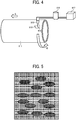
- the intermediate transfer belt 8 can be produced using a polyimide solution through spin coating illustrated in FIG. 4 .
- spin coating a cylindrical molding tube 911, which is dimensioned to have an outer diameter corresponding to the length of the intermediate transfer belt 8, is prepared.
- a nozzle 915 is disposed facing the outer face of the cylindrical molding tube 911.
- the nozzle 915 is coupled, via a tube, to a coating liquid container 914.
- the coating liquid container 914 is coupled to a compressor 917 via the tube.
- a blade 918 is disposed to level the applied coating liquid 916 on the outer face of the cylindrical molding tube 911.
- An operator or a worker rotates the cylindrical molding tube 911 in the direction indicated by arrow D in FIG. 4 , ejects the coating liquid 916 from the nozzle 915 onto the outer face of the cylindrical molding tube 911, and levels, with the blade 918, the coating liquid 916 on the outer face of the cylindrical molding tube 911.
- the operator moves the nozzle 915 and the blade 918 in the direction indicated by arrow E in FIG. 4 at a constant speed and applies the coating liquid 916 in a constant thickness on the cylindrical molding tube 911.
- the compressor 917 causes the nozzle 915 to eject a constant amount of the coating liquid 916.
- a film of the coating liquid 916 is produced on the outer face of the cylindrical molding tube 911.
- the film of the coating liquid 916 is dried upon application of heat and cooled.
- the cooled film serves as the base layer 81 (i.e., a belt base).
- an elastic layer 82 and the like are formed in the similar method.
- the film of the coating liquid 916 is formed on the cylindrical molding tube 911, the film is dried in a temperature range of from 80°C to 170°C to remove the solvent (drying process). Subsequently, the film is heated to a temperature range of from 250°C to 350°C for imide inversion (baking step). Then, a base layer 81 made of the polyimide resin film is obtained.
- the coating liquid 916 has a solid content of, for example, in a range of from 10% by mass to 40% by mass and a viscosity in a range of from 1 Pa ⁇ s to 100 Pa ⁇ s. Additionally, the conductant is uniformly included in the coating liquid 916 according to the common logarithm value of the surface resistivity of the intermediate transfer belt 8 required.
- the drying temperature is preferably in a range of from 100°C to 170°C. If the drying temperature in the drying process is too low, drying of the solvent in the polyimide precursor is not promoted. Then, even if the drying time is extended, the amount of remaining solvent is not easily reduced to a predetermined amount. If the drying temperature is too high, at an extremely early stage of the drying process, a dried film is formed on the surface of the polyimide precursor. The dried film may result in insufficient drying of the solvent inside the polyimide precursor. The dried film may cause a twist of the surface of the polyimide precursor coating after drying, resulting in a defect such as a crease on the coating surface. When the drying temperature is in the range of from 100°C to 170°C, the amount of remaining solvent is reduced to the predetermined amount, and a more preferable coat of the polyimide precursor is attained.
- the multilayered belt is peeled off from the cylindrical molding tube 911 and cut in predefined width to obtain the intermediate transfer belt 8.
- a first example of the intermediate transfer belt 8 is a double-layer belt including the base layer 81 made of polyimide and the elastic layer 82 overlying the front side (outer side in the loop) of the base layer 81.
- the surface resistivity of the belt front side (hereinafter “front surface resistivity”) is 11.3 log ⁇ / ⁇
- the surface resistivity of the belt back side (hereinafter “back surface resistivity”) is 11.3 log ⁇ / ⁇ .
- the volume resistivity of the belt is 9.7 log ⁇ cm.
- a second example of the intermediate transfer belt 8 is as follows.
- the intermediate transfer belt 8 is double-layered and includes the base layer 81 made of polyimide and the elastic layer 82 overlying the front side (outer side in the loop) of the base layer 81.
- the front surface resistivity of the belt is 12.5 log ⁇ / ⁇
- the back surface resistivity of the belt is 11.0 log ⁇ / ⁇ .
- the volume resistivity is 10.0 log ⁇ cm.
- a third example of the intermediate transfer belt 8 is as follows.
- the intermediate transfer belt 8 is double-layered, and the elastic layer 82 overlies the front side of the base layer 81 made of polyamideimide.
- the front surface resistivity of the belt is 11.3 log ⁇ / ⁇
- the back surface resistivity of the belt is 11.3 log ⁇ / ⁇ .
- the volume resistivity is 9.7 log ⁇ cm.
- the multilayered intermediate transfer belt 8 described above can attain desirable efficiency in primarily transferring toner images from the photoconductors 1 onto the intermediate transfer belt 8 and long life of the intermediate transfer belt 8.
- the inventors have found that use of a multilayered intermediate transfer belt increases the possibility of occurrence of uneven image density.
- the image density tends to become uneven particularly in black toner images in toner images of four colors (yellow, magenta, cyan, and black).
- the multilayered intermediate transfer belt 8 inevitably has an increased thickness and includes an interface between the layers. Accordingly, the electrical resistance is relatively high. To attain a necessary amount of primary transfer current, high voltage is used for the primary transfer bias.
- FIG. 11 illustrates an example structure of the primary transfer roller 9.
- the primary transfer roller 9 illustrated in FIG. 11 includes a core 91 and a roller body 92.
- the primary transfer roller 9 is a metal roller and the primary transfer bias of high voltage is applied thereto, a significant leak of current occurs due to severe electrical discharge between the photoconductor 1 and the primary transfer roller 9 made of metal. Accordingly, for the primary transfer roller 9, use of a roller that is not made of metal is preferred. A roller that is not made of metal, however, still causes a small amount of electrical discharge between the roller and the photoconductor 1 via the intermediate transfer belt 8. Such discharge locally occurs in a micro gap adjacent to the exit of the primary transfer nip, at which the intermediate transfer belt 8 is parted from the photoconductor 1. Such discharge is called “separating discharge”. Separating discharge does not uniformly occur but occurs corresponding to slight unevenness in resistance of the primary transfer roller 9.
- the separating discharge causes unevenness in the charge amount of the toner layer borne on the intermediate transfer belt 8.
- the unevenness in the charge amount results in differences in the rate of secondary transfer and results in uneven image density.
- the portion affected by the separating discharge is further charged (i.e., charge-up) to the side of the normal charge polarity of toner, and the charge amount increases.
- the margin for separating discharge is small, which is another cause of uneven image density.
- the margin for separating discharge is a difference between a bare minimum of the primary transfer current (for primary transfer of toner) and a smallest value of the primary transfer current to cause separating discharge. For example, assuming that the bare minimum of the primary transfer current is 40 ⁇ A and the smallest value of the primary transfer current to cause separating discharge is 80 ⁇ A, the margin for separating discharge is the difference therebetween, that is, 40 ⁇ A. Compared with single-layer belts, this difference tends to be small in multilayer belts.
- a minute flaw may be present inside the elastic layer 82, or a minute gap may be present between the base layer 81 and the elastic layer 82. Such minute flaw or minute gap can become an origin of electrical discharge, and separating discharge occurs easily.
- Uneven image density resulting from uneven charge amount of toner occurs mainly in a high gradation level portion (an image portion where the image density is relatively high).
- FIG. 5 is a schematic enlarged diagram illustrating an image portion of high gradation level in which image density is made uneven due to the uneven charge amount of toner.
- dot area coverage modulation rate by dithering is, for example, 80%.
- the image density of a portion affected by separating discharge increases in some cases and decreases in other cases.
- FIG. 5 illustrates a case where the image density has increased due to separating discharge.
- the image density is more likely to increase due to separating discharge.
- the rate of secondary transfer of the portion affected by separating discharge gradually decreases, and the difference in image density gradually decreases. The density difference becomes unnoticeable with time.
- an afterimage on the photoconductor 1 is emphasized by separating discharge and results in uneven image density.
- the uneven image density due to emphasizing of the afterimage on the photoconductor 1 mainly occurs in an image portion of low gradation level.
- FIG. 6 is a schematic enlarged diagram illustrating an image portion of low gradation level in which image density is made uneven due to emphasizing of the afterimage on the photoconductor 1.
- dot area coverage modulation rate by dithering is, for example, 10%.
- dot area coverage modulation rate by dithering is, for example, 10%.
- the discharge portion in the electrostatic latent image on the photoconductor 1 is emphasized as an afterimage.
- the emphasized afterimage adheres to an image portion of low gradation level in the primary transfer nip in subsequent rotation, the afterimage portion is not properly transferred in primary transfer and results in a void. Consequently, the image density becomes uneven.
- the following is another cause to increase the possibility of uneven image density particularly in black toner images, of the yellow, magenta, cyan, and black toner images.
- the primary transfer nip of black is extreme downstream in the sequence of primary transfer process.
- the charge amount becomes uneven due to separating discharge at the exit of the primary transfer nip of yellow.
- the yellow toner image is further affected by separating discharge at the exit of the primary transfer nip of magenta, the exit of the primary transfer nip of cyan, and the exit of the primary transfer nip of black.
- almost all yellow toner is charged to saturation. Accordingly, the unevenness in the charge amount is substantially eliminated at the time of transferring onto the recording sheet in the secondary transfer nip.
- the charge amount of the magenta toner image is made uneven by separating discharge at the exit of the primary transfer nip of magenta, the magenta toner image is repeatedly affected by the separating discharge at the exit of the primary transfer nip of cyan and the exit of the primary transfer nip of black. Then, the magenta toner image is almost entirely charged to saturation. Accordingly, the unevenness in the charge amount is substantially eliminated at the time of transferring onto the recording sheet in the secondary transfer nip.
- the charge amount of the cyan toner image is made uneven by separating discharge at the exit of the primary transfer nip of cyan, the cyan toner image is also affected by the separating discharge at the exit of the primary transfer nip of black. Then, the unevenness in the charge amount is alleviated. Accordingly, the unevenness in the charge amount is reduced at the time of transferring onto the recording sheet in the secondary transfer nip.
- the charge amount of the black toner image is made uneven by separating discharge at the exit of the primary transfer nip of black, and the black toner image as is enters the secondary transfer nip. Then, the unevenness in the charge amount causes a difference in secondary transfer capability and makes the image density uneven.
- the inventors consecutively printed black test toner images and evaluated the test toner images for uneven image density (image density uniformity).
- image density uniformity As the primary transfer roller 9K, three rollers, namely, a roller having a resistance of 10 6 ⁇ , a roller having a resistance of 10 6.5 ⁇ , and a roller having a resistance of 10 7 ⁇ were used, and image density uniformity was evaluated for each of the three rollers.
- the image density uniformity was evaluated in three ratings of good (image density is not uneven), acceptable (uneven is recognized slightly but is allowable), and poor (unevenness is noticeable).
- Table 1 presents the evaluation results of the experiment. Table 1 Number of sheets printed Roller resistance ( ⁇ ) 100,000 200,000 400,000 800,000 1,600,000 10 6 Good Good Good Good Good Good 10 6.5 Good Good Good Good Acceptable 10 7 Good Poor Poor Poor Poor Poor Poor Poor Poor Poor Poor Poor Poor Poor Poor
- the degree of uneven image density is acceptable even when the number of sheets printed is 1,600,000. Since the electrical resistance of the primary transfer roller 9K is reduced, the primary transfer bias output in constant-current control is reduced, thereby reducing the possibility of occurrence of separating discharge at the exit of the primary transfer nip of black.
- the image density is not uneven even when the number of sheets printed is 1,600,000. Therefore, when the resistance of the primary transfer roller 9K is smaller than 10 7 ⁇ , uneven image density caused by uneven charge amount of black toner resulting from separating discharge can be effectively inhibited.
- the primary transfer roller 9K for black toner has a resistance smaller than 10 7 ⁇ .
- the primary transfer rollers 9Y, 9M, and 9C for yellow, magenta, and cyan have a resistance not smaller than 10 7 ⁇ because image density unevenness is worsened if the resistance thereof is smaller than 10 7 ⁇ .
- the resistance is made lower to reduce the amount of charge-up of the toner image by separating discharge, when the toner image enters the primary transfer nip on the downstream side in the belt travel direction, a portion of the toner image is reversely transferred onto the photoconductor 1. Then, the image density becomes uneven.
- the primary transfer roller 9K which is disposed extreme downstream of the four primary transfer rollers 9Y, 9M, 9C, and 9K in the sequence of primary transfer, is lower in electrical resistance than the primary transfer rollers 9Y, 9M, and 9C for yellow, magenta, and cyan. With this feature, image density unevenness can be inhibited.
- Image density unevenness is also affected by the properties of toner.
- effects of charge retentivity and dielectric constant (permittivity) are large.
- Charge retentivity represents the degree how easily toner retains charges or how easily charges escape from the toner. For example, quantification can be made by keeping charged toner under a certain condition and then measuring the charge amount of the toner. If toner having a lower charge retentivity (the toner easily relieves charges) is subjected to uneven discharge, the toner is likely cause image density unevenness during secondary transferring. Even when frctionized in the developing device, the toner having the lower charge retentivity is not easily charged, and has a relatively small charge amount.
- the toner easily causes charge amount unevenness due to separating discharge at the exit of the primary transfer nip.
- the charge amount thereof is promptly saturated. Accordingly, the toner less easily causes charge amount unevenness.
- the resistance and the dielectric constant of toner affect the degree how easily charge amount unevenness is reflected in image density unevenness. If the secondary transfer current is insufficient in the secondary transfer nip, the strength of the secondary transfer electrical field is insufficient, and secondary transferring becomes defective particularly in image portions of high gradation level (e.g., solid image portions, in particular, in which multiple colors are superimposed). At that time, although, in a toner image, a portion in which the charge amount of toner is small (i.e., "small-charge portion") is secondarily transferred, a portion in which the charge amount is large (i.e., a large-charge portion) is less easily transferred.
- the toner In a case of toner having a small charge amount, the toner is charged in reverse (in the opposite polarity) by the discharges.
- the absolute value of charge amount decreases. Then, the toner causes defective transfer.
- toner also affect image density unevenness due to an afterimage.
- the effect is prominent when the charge retentivity of toner is low.
- developing capability increases.
- the developing bias and the charging bias are adjusted to lower values and the image density is adjusted to or close to a target value.
- the charging bias is small, it becomes difficult to delete the history of potentials on the photoconductor in the previous rotation of the photoconductor, and the residual potential is likely to appear as an afterimage.
- the developing capability is high in the first place, a slight potential difference results in a large density difference. Accordingly, for the station in which the charge retentivity of toner is low, reducing discharge unevenness in the transfer position is preferred, which coincides with reducing the charge amount unevenness of toner on the belt.
- the image forming apparatus 500 uses, as the black toner, a toner higher in dielectric constant and lower in resistance than the yellow, magenta, and cyan toners used in the image forming apparatus 500. This feature can better inhibit the occurrence of image density unevenness due to the charge amount unevenness of toner.
- the pressure of the secondary transfer nip is preferably relatively high to sufficiently press the elastic layer 82. Therefore, for example, in one embodiment, to change the pressure of the secondary transfer nip, the image forming apparatus 500 further includes a structure to change the force with which the secondary transfer roller 18 is pressed against the secondary-transfer backup roller 12.
- the pressure of the secondary transfer nip is relatively high, the recording sheet is less easily separated from the intermediate transfer belt 8 at the exit of the secondary transfer nip. The recording sheet may fail to leave the intermediate transfer belt 8.
- FIG. 7 which includes a transfer-transport belt
- a transfer-transport belt 51 is nipped between the secondary-transfer backup roller 12 and the secondary transfer roller 18.
- the transfer-transport belt 51 is an endless belt and entrained taut around the rollers disposed inside the loop thereof, namely, the secondary transfer roller 18, a first support roller 52, a second support roller 53, and a third support roller 54.
- the transfer-transport belt 51 rotates counterclockwise in FIG. 7 .
- the front side of the transfer-transport belt 51 is cleaned by a cleaning blade 55.
- the third support roller 54 nips the transfer-transport belt 51, together with the cleaning blade 55, and serves as a tension roller.
- the transfer-transport belt 51 is a single-layer belt and made of, for example, polyimide (PI), polyamide imide (PAI), polyvinyliden fluoride (PVDF), or the like.
- the transfer-transport belt 51 is about 80 ⁇ m in thickness.
- the recording sheet is separated by self stripping from the transfer-transport belt 51 due to curvature.
- Such a structure can smoothly transport a variety of sheets including thin paper, thick paper, and rugged sheets.
- the roller i.e., a target roller to be detected
- load is applied to the roller.
- a bias is applied to the roller, and the resistance thereof is obtained from the voltage and current at that time.
- measurement can be made while either the roller is rotated or the roller is kept stationary.
- the resistance is measured in the following state. While a dedicated tool rotates the roller at a speed of 30 revolutions per minute (rpm), the roller is pressed from both ends in the axial direction of the roller to apply a load of 1 N (in total of both ends) to the roller, and a bias of 1 kV is applied to the roller.
- the measurement is made under a temperature of 23°C and a relative humidity (RH) of 50%.
- RH relative humidity
- each of the primary transfer rollers 9Y, 9M, 9C, and 9K for yellow, magenta, cyan, and black is a rubber roller. That is, the roller body 92 is made of rubber.
- each of the primary transfer rollers 9Y, 9M, 9C, and 9K for yellow, magenta, cyan, and black is a sponge roller (the roller body 92 is made of foam sponge), the sponge roller abounds in projections and recesses at the surface thereof. Accordingly, the sponge roller can increase the possibility of separating discharge at the exit of the primary transfer nip.
- the projections and recesses at the surface make the electrical resistance uneven, which is another cause that increases the possibility of separating discharge.
- the primary transfer rollers 9Y, 9M, 9C, and 9K are rubber rollers, the surfaces thereof are smooth and free of bubble pores. Accordingly, the resistance is less likely to become uneven in the surface direction.
- rubber rollers can inhibit the occurrence of separating discharge at the exit of the primary transfer nip. Table 2 below presents results of consecutive printing test using a rubber roller for the primary transfer roller 9K. Table 2 Number of sheets printed Roller resistance ( ⁇ ) 100,000 200,000 400,000 800,000 1,600,000 10 6 Good Good Good Good Good 10 6.5 Good Good Good Good Good 10 7 Good Good Poor Poor Poor Poor
- metal rollers are used as the primary transfer rollers 9Y, 9M, 9C, and 9K for yellow, magenta, cyan, and black.
- primary transfer of yellow, magenta, cyan, and black instead of direct transfer-bias application, indirect transfer-bias application is used.
- the intermediate transfer belt 8 has a back surface resistivity of 10 Log ⁇ / ⁇ .
- Table 3 presents the results of evaluation of consecutive print of black test toner images in the configuration according to Example 2. Table 3 Number of sheets printed 100,000 200,000 400,000 800,000 1,600,000 Image density uniformity Good Good Good Good Good Good Good Good Good
- the primary transfer rollers 9Y, 9M, 9C, and 9K for yellow, magenta, cyan, and black are made of metal
- the electrical resistance of the metal material is made different between the primary transfer roller 9K for black (located extreme downstream in the four primary transfer rollers 9 in the sequence of transfer process) and the other primary transfer rollers 9Y, 9M, and 9C.
- the primary transfer roller 9K is lower in electrical resistance than the primary transfer rollers 9Y, 9M, and 9C.
- the primary transfer roller 9K for black is a metal roller
- each of the primary transfer rollers 9Y, 9M, and 9C is a sponge roller or a rubber roller.
- direct transfer-bias application is employed in transfer of yellow, magenta, and cyan.
- metal rollers are used as the primary transfer rollers 9Y, 9M, 9C, and 9K for yellow, magenta, cyan, and black.
- direct transfer-bias application is used in primary transfer of yellow, magenta, cyan, and black.
- the intermediate transfer belt 8 is increased in thickness to have an increased resistance. Since the intermediate transfer belt 8 has the increased resistance, even in the configuration in which the primary transfer rollers 9Y, 9M, 9C, and 9K made of metal are used in direct transfer-bias application, a severe discharge does not occur between the primary transfer roller 9 and the photoconductor 1. Accordingly, this structure can inhibit image failure caused by excessive leak of current.
- Example 3 Compared with Example 2 employing indirect transfer-bias application, vibration of the intermediate transfer belt 8 and banding can be suppressed in Example 3 owing to direct transfer-bias application.
- the results of evaluation of consecutive print of black test toner images in the configuration according to Example 3 are similar to the results presented in Table 3.
- the primary transfer rollers 9Y, 9M, 9C, and 9K for yellow, magenta, cyan, and black are made of metal
- the electrical resistance of the metal material is made different between the primary transfer roller 9K for black (located extreme downstream in the four primary transfer rollers 9 in the sequence of transfer process) and the other primary transfer rollers 9Y, 9M, and 9C.
- the primary transfer roller 9K is lower in electrical resistance than the primary transfer rollers 9Y, 9M, and 9C.
- Example 4 the following feature is added to the image forming apparatus according to any one of Examples 1 through 3. That is, one of the three colors of yellow, magenta, and cyan is disposed extreme downstream in the sequence of primary transfer, and black is not disposed extreme downstream in the sequence of primary transfer. Further, the primary transfer roller 9 (9Y, 9M, or 9C) disposed extreme downstream in the four colors in the sequence of primary transfer, is lower in electrical resistance than the other three primary transfer rollers 9.
- FIG. 9 is a block diagram illustrating a portion of electrical circuitry of the image forming apparatus according to Example 5.
- the controller 900 includes a central processing unit (CPU), a random access memory (RAM), a read only memory (ROM), a nonvolatile memory, and the like.
- the controller 900 is configured to control driving of various devices in the image forming apparatus 500 and perform predetermined computation.
- a power supply 901 outputs the primary transfer biases applied to the primary transfer rollers 9Y, 9M, 9C, and 9K, respectively, and controls the primary transfer biases for yellow, magenta, cyan, and black individually under constant-current control.
- the controller 900 stores target output values of primary transfer currents for yellow, magenta, cyan, and black, respectively.
- the power supply 901 is configured to output the primary transfer bias (i.e., first transfer bias) applied to the primary transfer roller 9K separately from the primary transfer biases (i.e., second transfer bias) applied to the primary transfer roller 9Y, 9M, and 9C.
- the primary transfer bias i.e., first transfer bias
- the primary transfer biases i.e., second transfer bias
- the power supply 901 adjusts the voltage output value for the primary transfer bias so that the output current value of the primary transfer bias conforms to the target output value for yellow.
- An environment sensor 902 detects temperature and relative humidity (RH) inside the image forming apparatus (i.e., internal environment) and outputs the detection results to the controller 900.
- the controller 900 calculates an absolute humidity based on the detected temperature and the detected relative humidity transmitted from the environment sensor 902. Based on the calculation, the controller 900 identifies the internal environment with one of a low temperature and low humidity (LL) environment, a moderate temperature and moderate humidity (MM) environment, and a high temperature and high humidity (HH) environment.
- LL low temperature and low humidity
- MM moderate temperature and moderate humidity
- HH high temperature and high humidity
- the internal environment in which the absolute humidity is equal to or smaller than 8 kg/kg is identified as the LL environment
- the internal environment in which the absolute humidity is greater than 8 kg/kg and not greater than 15 kg/kg is identified as the MM environment
- the internal environment in which the absolute humidity is greater than 15 kg/kg is identified as the HH environment.
- the controller 900 renews the target output values of the primary transfer biases for yellow, magenta, cyan, and black in constant-current control according to Table 4 below.
- the controller 900 outputs, to the power supply 901, the renewed target output values of the primary transfer biases for yellow, magenta, cyan, and black.
- the power supply 901 updates the target output values for yellow, magenta, cyan, and black stored until then to the renewed values transmitted from the controller 900. From then, the power supply 901 controls the output values of the primary transfer biases for yellow, magenta, cyan, and black under constant-current control based on the updated target output values for yellow, magenta, cyan, and black.
- the electrical resistances of the primary transfer rollers 9Y, 9M, and 9C for yellow, magenta, and cyan are higher, and the degree of margin for separating discharge at the exit of the primary transfer nip is lower.
- the degree of margin decreases as the temperature and the humidity descend. Accordingly, as can be known from Table 4, the target output values of the primary transfer currents for yellow, magenta, and cyan are reduced in the order from the HH environment to the MM environment, and further to the LL environment.
- the electrical resistance of the primary transfer roller 9K for black is relatively low to increase the degree of margin for separating discharge at the exit of the primary transfer nip. Accordingly, the possibility of separating discharge is not large even in the LL environment. Accordingly, regarding black, as can be known from Table 4, the target output value of the primary transfer current in LL environment is identical to the output value in the MM environment. With this setting, even in the LL environment, a desirable primary transfer current flows to the primary transfer nip of black. Regarding black, the warm-up speed of primary transfer is slow because of the relatively low electrical resistance of the primary transfer roller 9K. Accordingly, attaining desirable primary transfer rate becomes difficult as the primary transfer current is reduced. However, such an inconvenience is inhibited with the setting presented in Table 4. Additionally, without reducing the target output value, small uniform separating discharges are caused to occur to give desirable charges to the black toner on the belt, thereby increasing the average charge amount of toner.
- the target output value in the HH environment differs between black and the other three colors (yellow, magenta, and cyan).
- black it is preferable to generate uniform separating discharges to a certain degree to slightly increase the charge amount of black toner. Accordingly, the target output value in the HH environment for black is larger than that for yellow, magenta, and cyan. In other words, the target output values for yellow, magenta, and cyan are smaller than that for black.
- the warm-up speed of primary transfer is relatively fast.
- the electrical resistances of the primary transfer rollers 9Y, 9M, and 9C for yellow, magenta, and cyan are relatively high, the warm-up speed of primary transfer is accelerated.
- the electrical resistance of the primary transfer roller 9K is relatively low, the warm-up speed of primary transfer is not so fast. Rather, the target output value is made large to attain uniform separating discharges. Thus, the electrical resistances of the primary transfer rollers 9 and the target output values are adjusted for individual colors to attain desirable image quality in each color.
- the photoconductor 1K for black is larger in diameter than the photoconductors 1Y, 1M, and 1C for yellow, magenta, and cyan.
- the diameter of the photoconductor 1K is 100 mm, whereas the diameters of the photoconductors 1 for yellow, magenta, and cyan are 60 mm similarly to the above-described embodiment.
- the frequency of output of black images is highest among the four colors.
- the replacement time of the photoconductor 1K can be similar to that of the photoconductors 1Y, 1M, and 1C for yellow, magenta, and cyan images, which are less frequently output, to facilitate maintenance work.
- the micro gap at the exit of the primary transfer nip, where the photoconductor 1K contacts the intermediate transfer belt 8 is larger compared with yellow, magenta, and cyan. Accordingly, compared with a case where the diameter of the photoconductor 1K is not increased, separating discharge more easily occurs at the exit of the primary transfer nip. Still, since the electrical resistance of the primary transfer roller 9K is relatively low, the occurrence of image density unevenness can be suppressed.
- one or more aspects of this disclosure can adapt to configurations using a power supply to output the primary transfer biases under constant-voltage control.
- the target output value of the transfer bias, controlled under constant-voltage control, applied to the transfer bias member (e.g., the primary transfer roller 9) located extreme downstream in the sequence of primary transfer is made lower than the target output value applied to the other transfer bias members so that a desirable amount of transfer current flows to each of the multiple transfer nips.
- the transfer bias member located extreme downstream in the sequence of primary transfer is made lower in potentials than the other transfer bias members, thereby inhibiting the occurrence of separating discharge at the exit of the transfer nip located extreme downstream.
- the description above concerns structures in which a toner image is primarily transferred from the image bearer onto the intermediate transfer belt 8 and secondarily transferred therefrom onto the recording sheet.
- one or more aspects of this disclosure can adapt to a structure in which the toner image is directly transferred from the image bearer onto the recording sheet carried on the surface of the belt.
- the image density is not made uneven by the unevenness in secondary transfer capability caused by uneven charge amount resulting from separating discharge.
- the image density can be made uneven by emphasizing of the afterimage on the image bearer due to separating discharge.
- Such image density unevenness can be inhibited when the resistance of the transfer bias member located extreme downstream in the sequence of primary transfer is made lower than the resistances of the other transfer bias members.
- Aspect A concerns an image forming apparatus that includes a plurality of image bearers (e.g., photoconductors 1Y, 1M, 1C, and 1K); a plurality of image forming devices (e.g., the process units 6Y, 6C, 6M, and 6K) to form toner images on the plurality of image bearers, respectively; an endless belt (e.g., the intermediate transfer belt 8) to sequentially contact the plurality of image bearers to form transfer nips; and a plurality of transfer bias members (e.g., the primary transfer rollers 9Y, 9M, 9C, and 9K), each of which is disposed, via the endless belt, opposing or adjacent to the respective one of the plurality of image bearers.
- image bearers e.g., photoconductors 1Y, 1M, 1C, and 1K
- image forming devices e.g., the process units 6Y, 6C, 6M, and 6K
- an endless belt e.g., the intermediate transfer belt 8
- Transfer biases are respectively applied to the plurality of transfer bias members in a state in which the plurality of transfer bias members are in contact with the belt.
- a toner image is transferred from the image bearer onto the surface of the belt or a recording medium conveyed by the belt.
- the belt includes a base layer (81) and at least one layer (82) superimposed on the front side of the base layer.
- the plurality of transfer bias members includes a downstream transfer bias member (e.g., the primary transfer roller 9K) located extreme downstream among the plurality of transfer bias members in a sequence of transfer process (i.e., located extreme downstream in the direction of rotation of the belt) and at least one upstream transfer bias member (e.g., the primary transfer roller 9Y) located upstream from the downstream transfer bias member, and the downstream transfer bias member is lower in electrical resistance than at least one upstream transfer bias member.
- a downstream transfer bias member e.g., the primary transfer roller 9K located extreme downstream among the plurality of transfer bias members in a sequence of transfer process (i.e., located extreme downstream in the direction of rotation of the belt)
- at least one upstream transfer bias member e.g., the primary transfer roller 9Y located upstream from the downstream transfer bias member
- Such a multilayered belt has a relatively large thickness and includes an interface between the layers. Accordingly, the electrical resistance of the belt is relatively high.
- a transfer bias of high voltage is applied to the transfer bias member, and the potential of the transfer bias member becomes significantly high. Then, separating discharge occurs in the micro gap between the image bearer and the belt at the exit of the transfer nip, and the separating discharge is likely to cause unevenness in the charge amount of the toner image on the belt.
- the transfer bias member located extreme downstream in the sequence of transfer process is lower in electrical resistance than the rest of the transfer bias members.
- the transfer bias applied to the extreme downstream transfer bias member is made lower than that applied to the rest of the plurality of transfer bias members, the occurrence of separating discharge at the exit of the extreme downstream transfer nip can be inhibited.
- the uneven charge amount caused by the separating discharge at the exit of the transfer nip can be inhibited, thereby inhibiting uneven image density caused by the uneven charge amount.
- a toner image transferred onto the belt in the upstream transfer nip (i.e., an upstream toner image) repeatedly receives relatively weak separating discharge at the exit of each of the upstream transfer nip and the downstream transfer nip.
- the upstream toner image is gradually charged to a charge amount lower than saturated charge amount, and the unevenness in the charge amount is gradually worsened.
- the unevenness in the charge amount of the upstream toner image is worsened.
- the transfer bias member located extreme downstream is lower in electrical resistance than the rest of the plurality of transfer bias members.
- the uneven charge amount caused by the separating discharge at the exit of the transfer nip can be inhibited, thereby inhibiting uneven image density caused by the uneven charge amount.
- the extreme downstream toner image is subjected to the relatively weak separating discharge to reduce the unevenness in the charge amount thereof. This feature can suppress image density unevenness due to the charge amount unevenness.
- At least one of the plurality of layers of the belt is made of a material containing an ion conductant.
- the material containing an ion conductant inhibits decreases in the electrical resistance of the belt even when the transfer bias of high voltage is applied to the belt. Accordingly, unsteady image quality caused by fluctuations in the electrical resistance can be inhibited.
- the image forming apparatus includes a power supply (e.g., the power supply 901) to apply transfer biases to the plurality of transfer bias members, and the power supply is configured to individually output, under constant-current control, a first transfer bias applied to the transfer bias member located extreme downstream and a second transfer bias applied to at least one of the rest of the plurality of transfer bias members.
- the image forming apparatus further includes an environment detector (e.g., the environment sensor 902) to detect an environment in or around the image forming apparatus, and a controller (e.g., the controller 900) to correct a first target value of the first transfer bias and a second target value of the second transfer bias, which are output under constant-current control from the power supply.
- the controller corrects the first and second target values based on the detection result generated by the environment detector.
- the controller is further configured to correct the first target value and the second target value according to different algorithms.
- the transfer bias can be controlled suitably for a combination of the electrical resistance of the transfer bias member and the environment, thereby inhibiting image quality degradation resulting from an unfit transfer bias.
- an extreme downstream image forming device located extreme downstream in the sequence of transfer process contains toner that is lower in volume resistivity than toners contained in the rest of the plurality of image forming devices.
- the extreme downstream image forming device forms toner images using toner lower in volume resistivity than toners used in the rest of the image forming devices.
- the toner transferred from the image bearer onto the belt in the extreme downstream transfer nip (hereinafter “toner transferred in the extreme downstream transfer nip”) is lower in volume resistivity than toners transferred onto the belt in the transfer nips other than the extreme downstream transfer nip. Accordingly, the occurrence of separating discharge at the exit of the extreme downstream transfer nip is inhibited. Therefore, uneven charge amount of the toner transferred in the extreme downstream transfer nip resulting from such separating discharge is inhibited, and this configuration can better inhibit uneven image density caused by uneven charge amount of the toner image transferred onto the belt in the extreme downstream transfer nip.
- an extreme downstream image forming device located extreme downstream in the sequence of transfer process contains toner that is higher in dielectric constant than toners contained in the rest of the plurality of image forming devices.
- the extreme downstream image forming device forms toner images using toner higher in dielectric constant than toners used in the rest of the image forming devices
- the toner transferred in the extreme downstream transfer nip is higher in dielectric constant than toners transferred onto the belt in the transfer nips other than the extreme downstream transfer nip. Accordingly, the occurrence of separating discharge at the exit of the extreme downstream transfer nip is inhibited. Therefore, uneven charge amount of the toner transferred in the extreme downstream transfer nip resulting from such separating discharge is inhibited, and this configuration can better inhibit uneven image density caused by uneven charge amount of the toner image transferred onto the belt in the extreme downstream transfer nip.
- black toner is used to form a toner image on the image bearer located extreme downstream in the plurality of image bearers in the sequence of transfer process.
- the black toner contains a colorant including carbon black, which excels in conductivity. That is, the electrical resistance of the toner transferred in the extreme downstream transfer nip can be easily made lower than that of the toners transferred in other transfer nips. Alternatively, the dielectric constant of the toner transferred in the extreme downstream transfer nip can be easily made higher than that of the toners transferred in other transfer nips.
- the transfer bias member located extreme downstream in the sequence of transfer process has an electrical resistance lower than 10 7 ⁇ .
- the occurrence of separating discharge at the exit of the transfer nip located extreme downstream is effectively inhibited.
- each of the plurality of transfer bias members includes a foam sponge as a surface layer (e.g., the roller body 92).
- the transfer bias member having a surface layer made of foam sponge can flexibly deform to inhibit damage to the image bearer given by the substance.
- each of the plurality of transfer bias members is a rubber roller having a smooth surface.
- the surface of the transfer bias member is made of a material higher in smoothness than foam sponge, the occurrence of separating discharge at the exit of the extreme downstream transfer nip can be better inhibited, compared with a case where the transfer bias member is made of foam sponge.
- the transfer bias member located extreme downstream in the sequence of transfer process has a volume resistivity lower than 10 7 ⁇ cm.
- the transfer bias member located extreme downstream in the sequence of transfer process is made of metal.
- the electrical resistance does not increase with elapse of time. Accordingly, exaggeration of separating discharge caused by increases in the electrical resistance can be avoided for a long time.
- the transfer bias member located extreme upstream in the sequence of transfer process has an electrical resistance higher than 10 7 ⁇ .
- Such a structure promotes separating discharge in the extreme upstream transfer nip, thereby promoting charge-up of toner by the separating discharge. Therefore, the toner transferred onto the belt in the extreme upstream transfer nip is charged up to the saturated charge amount by the separating discharge at the exit of the downstream transfer nip, thereby equalizing the charge amount of the toner and inhibiting the occurrence of image density unevenness.
- an extreme downstream image bearer located extreme downstream in the sequence of transfer process is larger in diameter than the rest of the plurality of image bearers. This structure can expand the operational life of the extreme downstream image bearer.
- Aspect O concerns an image formation method that includes a step of endlessly moving an endless belt to sequentially contact a plurality of image bearers to form a transfer nip at each contact position with respective one of the plurality of image bearers; a step of forming a toner image; a step of applying a transfer bias to each of a plurality of transfer bias members, each of which sandwiching the belt together with respective one of the plurality of the image bearers; and a step of transferring, in each of the transfer nips, a toner image from the image bearer onto either the surface of the belt or a recording medium carried on the belt.
- the method is used in an image forming apparatus in which the belt includes a base layer and at least one layer superimposed on the front side of the base layer.
- the plurality of transfer bias members includes an upstream transfer bias member (e.g., the primary transfer roller 9Y) and a downstream transfer bias member (e.g., the primary transfer roller 9K) respectively located extreme upstream and extreme downstream in a sequence of transfer process (i.e., located extreme downstream in the direction of rotation of the belt), and the downstream transfer bias member is lower in electrical resistance than the upstream transfer bias member.
- an upstream transfer bias member e.g., the primary transfer roller 9Y
- a downstream transfer bias member e.g., the primary transfer roller 9K
Landscapes
- Physics & Mathematics (AREA)
- General Physics & Mathematics (AREA)
- Electrostatic Charge, Transfer And Separation In Electrography (AREA)
- Color Electrophotography (AREA)
Abstract
Description
- Embodiments of the present invention generally relate to an image forming apparatus, such as a copier, a printer, a facsimile machine, or a multifunction peripheral having at least two of copying, printing, facsimile transmission, plotting, and scanning capabilities, and an image formation method.
- There are known image forming apparatuses in which an endless belt sequentially contacts multiple image bearers, from which toner images are transferred onto the belt in the positions (i.e., transfer nips) where the belt contacts the multiple image bearers.
- For example, an image forming apparatus described in
JP-2006-195143-A1 Patent Document 1") includes an endless intermediate transfer belt that moves while sequentially contacting multiple photoconductors serving as image bearers, and the contact positions with the photoconductors are called primary transfer nips. The image forming apparatus further includes multiple primary-transfer bias rollers. A transfer bias is applied to each of the primary-transfer bias rollers in a state in which the primary-transfer bias roller sandwiches the intermediate transfer belt together with the corresponding one of the photoconductors. In each of the primary transfer nips, the toner image is primarily transferred from the photoconductor and superimposed one on another on the intermediate transfer belt. Subsequently, in a secondary transfer nip where the intermediate transfer belt contacts a secondary-transfer bias roller, the superimposed image is transferred from the intermediate transfer belt onto a recording sheet (i.e., a recording medium) nipped in the secondary transfer nip. - The image forming apparatus described in
Patent Document 1 uses, as the intermediate transfer belt, a single-layer belt including polyimide (PI) as a main component and having a thickness of 100 µm. The image forming apparatus described inPatent Document 1 employs direct transfer-bias application, in which the transfer roller contacts a back side of the belt the contact position between the photoconductor and the belt. - Since polyimide has a relatively high rigidity, the belt made of polyimide can be a long-life belt with elongation of the belt inhibited. When the intermediate transfer belt is made of a material having a relatively high rigidity, however, cohesion between the intermediate transfer belt and the photoconductor is lower, and efficiency in primary transfer of toner images is degraded. Additionally, it is difficult to secondarily transfer toner images onto recording sheets having a lower surface smoothness.
- Currently, in addition to plain paper, use of special sheets, such as paper having an embossed surface and thermal transfer paper used for iron print, is increasing. If such special sheets are used in the image forming apparatus described in
Patent Document 1, the possibility of defective transfer is higher in secondarily transferring a superimposed toner image onto the sheet from the intermediate transfer belt, compared with image transfer onto plain paper. - In the intermediate transfer belt of the image forming apparatus described in
Patent Document 1, carbon black is added to polyimide to adjust the electrical resistance of the intermediate transfer belt.Patent Document 1 states that the volume resistivity of the intermediate transfer belt is from 108 to 1012 Ω·cm. - However, high voltage is required in applying the primary transfer bias to such an intermediate transfer belt having a relatively high electrical resistance to cause a desired primary transfer current to flow to the primary transfer nip. When a primary transfer bias of high voltage is applied to the intermediate transfer belt to which carbon black is added to adjust electrical resistance, practical electrical resistance of the entire belt is reduced irregularly, making the primary transfer current unstable. Therefore, it is conceivable that the volume resistivity is preferably lower than the range mentioned in
Patent Document 1. - In such a configuration, to attain desirable transfer rate of the toner image in primary transfer and extended life of the intermediate transfer belt, it is preferable that the intermediate transfer belt is multilayered and includes a flexible layer to tightly contact the photoconductors and a rigid layer to restrict elongation of the belt. The inventors, however, have found that use of a multilayered intermediate transfer belt increases the possibility of uneven image density and recognize there is a need for balancing desirable efficiency in transferring, long life of a transfer belt, and inhibition of uneven image density.
- In order to achieve the above-described object, there is provided an image forming apparatus according to
claim 1. Advantageous embodiments are defined by the dependent claims. - Advantageously, the image forming apparatus includes a plurality of image bearers; a plurality of image forming devices to form toner images on the plurality of image bearers, respectively; an endless belt including a plurality of layers and disposed in contact with the plurality of image bearers to form transfer nips; and a plurality of transfer bias members. To each of the transfer bias members, a transfer bias is applied in a state in which the transfer bias member sandwiches the endless belt together with one of the plurality of image bearers to transfer a toner image from the one of the plurality of image bearers onto a surface of the endless belt or a recording medium conveyed by the endless belt in each of the transfer nips. Of the plurality of transfer bias members, a downstream transfer bias member, which is located extreme downstream in a sequence of transfer process, is lower in electrical resistance than an upstream transfer bias member, which is located extreme upstream in the sequence of transfer process.
- Additionally, there is provided an image formation method. Advantageously, the image forming method includes a step of endlessly moving an endless belt to sequentially contact a plurality of image bearers to form a transfer nip at each contact position with one of the plurality of image bearers; a step of applying a transfer bias to each of a plurality of transfer bias members, each of which sandwiching the endless belt together with one of the plurality of image bearers; a step of forming a toner image on at least one of the plurality of image bearers; and a step of transferring, in the transfer nip, the toner image from at least one of the plurality of image bearers onto either a surface of the endless belt or a recording medium carried on the endless belt. The endless belt is multilayered. Of the plurality of transfer bias members, a downstream transfer bias member, which is located extreme downstream in a sequence of transfer process, is lower in electrical resistance than an upstream transfer bias member, which is located extreme upstream in the sequence of transfer process.
- Accordingly, the occurrence of uneven image density is inhibited while attaining desirable transfer rate of toner images transferred from an image bearer onto a belt and extended life of the belt.
- A more complete appreciation of the disclosure and many of the attendant advantages thereof will be readily obtained as the same becomes better understood by reference to the following detailed description when considered in connection with the accompanying drawings, wherein:
-
FIG. 1 is a schematic diagram of an image forming apparatus according to an embodiment; -
FIG. 2 is a schematic view of a transfer nip and an adjacent portion in indirect transfer-bias application; -
FIG. 3 is a schematic view of a transfer nip and an adjacent portion in direct transfer-bias application; -
FIG. 4 is a schematic view of a method to produce a belt using spin coating; -
FIG. 5 is a schematic enlarged diagram illustrating an image portion of high gradation level (for example, dot area coverage modulation rate by dithering is 80%) in which image density is made uneven due to uneven charge amount of toner; -
FIG. 6 is a schematic enlarged diagram illustrating an image portion of low gradation level (for example, dot area coverage modulation rate by dithering is 10%) in which image density is made uneven due to emphasizing of the afterimage on the photoconductor; -
FIG. 7 is a schematic view of a secondary transfer nip and an adjacent portion of an image forming apparatus according to a variation; -
FIG. 8 is a diagram of measurement of roller resistance; -
FIG. 9 is a block diagram illustrating electrical circuitry of the image forming apparatus according to Embodiment 5; -
FIG. 10 is a schematic cross-sectional view illustrating a layer structure of an intermediate transfer belt according to an embodiment; and -
FIG. 11 is a schematic cross-sectional view illustrating a layer structure of primary transfer roller according to an embodiment. - The accompanying drawings are intended to depict embodiments of the present invention and should not be interpreted to limit the scope thereof. The accompanying drawings are not to be considered as drawn to scale unless explicitly noted.
- In describing embodiments illustrated in the drawings, specific terminology is employed for the sake of clarity. However, the disclosure of this patent specification is not intended to be limited to the specific terminology so selected, and it is to be understood that each specific element includes all technical equivalents that operate in a similar manner and achieve a similar result.
- Referring now to the drawings, wherein like reference numerals designate identical or corresponding parts throughout the several views thereof, and particularly to
FIG. 1 , an image forming apparatus according to an embodiment of the present invention is described. As used herein, the singular forms "a", "an", and "the" are intended to include the plural forms as well, unless the context clearly indicates otherwise. - It is to be noted that the suffixes Y, M, C, and K attached to each reference numeral indicate only that components indicated thereby are used for forming yellow, magenta, cyan, and black images, respectively, and hereinafter may be omitted when color discrimination is not necessary.
- For example, the image forming apparatus according to the present embodiment is a printer employing a tandem system and an intermediate transfer.
-
FIG. 1 is a schematic diagram illustrating animage forming apparatus 500 according to the present embodiment. - The
image forming apparatus 500 includes fourprocess units - The
process units shaped photoconductors photoconductors 1") serving as image bearers, respectively. Around thephotoconductor 1, a charging device 2 (2Y, 2M, 2C, or 2K), a developing device 5 (5Y, 5M, 5C, or 5K), a drum cleaner 4 (4Y, 4M, 4C, or 4K) and a discharger are disposed. Theprocess units - Above the process units 6, an optical writing unit is disposed. The optical writing unit irradiates the surfaces of the
photoconductors 1 with laser beams L to optically write electrostatic latent images thereon. - Below the four process units 6, a
transfer unit 7 is disposed. Thetransfer unit 7 includes an endlessintermediate transfer belt 8 and a plurality of tension rollers disposed inside the loop of theintermediate transfer belt 8. Outside the loop, thetransfer unit 7 further includes asecondary transfer roller 18, atension roller 16, abelt cleaner 100, and alubrication device 200. - Disposed inside the loop of the
intermediate transfer belt 8 are fourprimary transfer rollers primary transfer rollers 9"), a drivenroller 10, a driving roller 11, a secondary-transfer backup roller 12, three cleaning-backup rollers roller 17. A portion of theintermediate transfer belt 8 is entrained around each of these rollers, and these rollers serves as the tension rollers to keep theintermediate transfer belt 8 taut. It is not necessary that the cleaning-backup rollers intermediate transfer belt 8 as long as the cleaning-backup rollers intermediate transfer belt 8 rotates. As the driving roller 11 rotates counterclockwise (i.e., the belt travel direction) in the drawing, driven by a driver, theintermediate transfer belt 8 rotates (that is, the surface thereof moves endlessly) counterclockwise in the drawing. - The
primary transfer rollers intermediate transfer belt 8, serve as transfer bias applicators, and theintermediate transfer belt 8 is nipped between theprimary transfer rollers photoconductors intermediate transfer belt 8 contacts thephotoconductors primary transfer roller 9, a power supply apples a transfer bias, which is opposite in polarity from the toner. - Additionally, the
intermediate transfer belt 8 is nipped between the secondary-transfer backup roller 12 disposed inside the loopedintermediate transfer belt 8 and thesecondary transfer roller 18 disposed outside the loopedintermediate transfer belt 8. Thus, the outer face (front side) of theintermediate transfer belt 8 contacts thesecondary transfer roller 18, and the contact portion therebetween serves as a secondary transfer nip. To the secondary-transfer backup roller 12, a power supply applies a secondary transfer bias, which is identical in polarity to the normal charge polarity of toner. Alternatively, the following structure can be used. A sheet conveyor belt is entrained around thesecondary transfer roller 18, several support rollers, and a driving roller. Theintermediate transfer belt 8 and the sheet conveyor belt are nipped between thesecondary transfer roller 18 and the secondary-transfer backup roller 12. - Additionally, the
intermediate transfer belt 8 is nipped between the cleaning-backup rollers intermediate transfer belt 8 and three cleaning brush rollers of thebelt cleaner 100, disposed outside the loopedintermediate transfer belt 8. The portions where the outer face of theintermediate transfer belt 8 contacts the three cleaning brush rollers serve as cleaning nips. Thebelt cleaner 100 is united with thetransfer unit 7 and replaceable together with thetransfer unit 7. When thetransfer unit 7 is removed from the body of the image forming apparatus 500 (hereinafter "apparatus body"), thebelt cleaner 100 is removable therefrom. Further, thebelt cleaner 100 includes a subunit. The subunit is mountable in and removable from thebelt cleaner 100 in a state in which thetransfer unit 7 and thebelt cleaner 100 are mounted in the apparatus body. Thebelt cleaner 100 is described in further detail later. - The
image forming apparatus 500 includes a sheet feeder that includes a sheet tray to contain recording sheets P, a sheet feeding roller to feed the sheet P from the sheet tray to a sheet feeding path, and the like. Further, a registration roller pair is disposed on the right of the secondary transfer nip in the drawing. The registration roller pair receives the recording sheet P fed from the sheet feeder and timely forwards the recording sheet P to the secondary transfer nip. On the left of the secondary transfer nip in the drawing, a fixing device is disposed. The fixing device receives the recording sheet P released from the secondary transfer nip and fixes an image on the recording sheet P. Further, toner supply devices to supply, as required, yellow, magenta, cyan, and black toners to the developingdevices - In response to image data transmitted from personal computers (client computers) or the like, the
image forming apparatus 500 drives the driving roller 11, thereby rotating theintermediate transfer belt 8. The tension rollers other than the driving roller 11 are driven to rotate as theintermediate transfer belt 8 rotates. Simultaneously, therespective photoconductors 1 of the process units 6 are rotated. In each process unit 6, while the charging device 2 uniformly charges the surface of thephotoconductor 1, the charged surface is irradiated with the laser beam L to form an electrostatic latent image thereon. Then, the developing device 5 develops the electrostatic latent image on thephotoconductor 1. Then, yellow, magenta, cyan, and black toner images are formed on thephotoconductors intermediate transfer belt 8. Thus, a four-color superimposed toner image is formed on the outer face of theintermediate transfer belt 8. - Meanwhile, in the sheet feeder, the sheet feeding roller feds the recording sheets P from the sheet tray one by one to the registration roller pair. Subsequently, the registration roller pair is driven to feed the recording sheet P to the secondary transfer nip, timed to coincide with the four-color toner image on the
intermediate transfer belt 8. Then, the four-color toner image is secondarily transferred at a time onto the recording sheet P. Thus, a full-color toner image is formed on the recording sheet P. Subsequently, the recording sheet P is transported from the secondary transfer nip to the fixing device, where the toner image is fixed on the recording sheet P. - After the yellow, magenta, cyan, and black toner images are primarily transferred onto the
intermediate transfer belt 8, thedrum cleaners photoconductors charging devices photoconductors belt cleaner 100 removes toner remaining on theintermediate transfer belt 8 after the toner image is secondarily transferred onto the recording sheet P. - On the right of the
process unit 6K for black inFIG. 1 , anoptical sensor unit 90 is disposed. Theoptical sensor unit 90 faces, across a predetermined gap, the outer face of theintermediate transfer belt 8. Theoptical sensor unit 90 emits light from a light-emitting element, reflects the light on either the outer face of theintermediate transfer belt 8 or the toner image on theintermediate transfer belt 8, and detects the level of reflected light with a light-receiving element. Based on the value of voltage output from such a sensor, a controller (e.g., acontroller 900 inFIG. 9 ) can detect the toner image on theintermediate transfer belt 8 and the image density (the amount of toner adhering per unit area) of the toner image. - The surface of the
intermediate transfer belt 8 is lubricated by thelubrication device 200 for protection. Thelubrication device 200 includes asolid lubricant 202, such as a block of zinc stearate, and anapplication brush roller 201 to contact thesolid lubricant 202. While rotating, theapplication brush roller 201 applies powdered lubricant, which is scraped off from thesolid lubricant 202, onto the surface of theintermediate transfer belt 8. Although theimage forming apparatus 500 includes thelubrication device 200, lubrication of theintermediate transfer belt 8 may be unnecessary depending on the type of toner, the material of theintermediate transfer belt 8, the surface friction coefficient of theintermediate transfer belt 8, and the like. - In applying the transfer bias to transfer a toner image in the contact portion between the belt and the photoconductor, there are two transfer types, namely, indirect transfer-bias application and direct transfer-bias application. In indirect transfer-bias application, as illustrated in
FIG. 2 , a transfer roller contacts a back side of the belt at a position shifted from the contact position between the photoconductor and the belt. In indirect transfer-bias application, the electrical charges transferred from the transfer roller to the belt are caused to flow, along the loop of the belt, to the primary transfer nip. Accordingly, the electrical resistance of the belt is preferably relatively low. For the transfer roller, a metal roller having a very small electrical resistance can be used. - In direct transfer-bias application, as illustrated in
FIG. 3 , the belt is nipped between the transfer roller and thephotoconductor 1, thus forming the transfer nip. - In the configuration described in
Patent Document 1, in which the intermediate transfer belt is a single layer belt and direct transfer-bias application is employed, if a primary transfer roller made of metal is used, severe electrical discharge may occur between thephotoconductor 1 and the primary transfer roller. Accordingly, use of a primary transfer roller made of metal is not preferred. It is preferred to use, as the primary transfer roller, a roller having a certain level of electrical resistance, such as a sponge roller or a rubber roller. The volume resistivity of the primary transfer roller is about 6 to 8 Log (Ω·cm), and a range of from 6.5 to 7.5 Log (Ω·cm) is preferred. Unless the electrical resistance of such level is exerted, the voltage value of the primary transfer bias can significantly fluctuate under constant-current control, depending on, for example, the charging potential of thephotoconductor 1 and the area of image writing. Then, stabilizing image quality becomes difficult. - As described above, there are two transfer types, namely, indirect transfer-bias application and direct transfer-bias application, in applying the transfer bias to transfer a toner image in the contact portion between the belt and the photoconductor.
- In indirect transfer-bias application, it is necessary that the resistance of the back side of the belt (hereinafter "belt back side") is lower compared with direct transfer-bias application. For example, according to measurement by Hiresta UPMCP-HT450 available from Mitsubishi Chemical Analytech Co., Ltd., in direct transfer-bias application, desirable transfer efficiency is attained when the resistance of the belt back side is from 11 to 12 Log ohms per square (Ω/□). By contrast, in indirect transfer-bias application, desirable transfer efficiency is attained when the resistance of the belt back side is from 9 to 10 Log Ω/□. In indirect transfer-bias application, the transfer bias is easily transmitted in the direction of loop of the belt and easily escapes from a ground roller. Thus, power saving efficiency is not good.
- Next, descriptions are given below of a distinctive feature of the image forming apparatus according to the present embodiment.
- In image forming apparatus according to the present embodiment, the
intermediate transfer belt 8 is multilayered and includes at least a base layer 81 (i.e., a belt base) made of a material having a relatively high rigidity and one layer superimposed on the front side of thebase layer 81 as illustrated inFIG. 10 . Above thebase layer 81, at least anelastic layer 82 made of a material that excels in elasticity is superimposed. As theelastic layer 82 flexibly deforms, theintermediate transfer belt 8 can tightly contact thephotoconductor 1 in the primary transfer nip. Then, desirable efficiency is attained in primary transfer of toner images. Additionally, as theelastic layer 82 flexibly deforms, theintermediate transfer belt 8 can conform to subtle surface unevenness of the recording sheet in the secondary transfer nip. Then, desirable efficiency is attained in secondary transfer of toner images even when the recording sheet has a low smoothness. - In addition, the
base layer 81 made of a material, such as polyimide, having a relatively high rigidity, can inhibit elongation of the belt over time, thereby extending the useful life of theintermediate transfer belt 8. It is to be noted that, in addition to thebase layer 81 and theelastic layer 82, theintermediate transfer belt 8 preferably includes a coating layer (i.e., a surface layer) made of a material having a better capability to release toner than theelastic layer 82. - Elastic materials usable for the
elastic layer 82 of theintermediate transfer belt 8 include elastic rubber and elastomer. Specifically, example elastic materials include, but are not limited to, butyl rubber, fluorine-based rubber, acrylic rubber, ethylene-propylene-diene monomer (EPDM), nitrile butadiene rubber, acrylonitrile-butadiene-styrene rubber, natural rubber, isoprene rubber, styrene-butadiene rubber, butadiene rubber, urethane rubber, and the like. Example elastic materials further include syndiotactic 1, 2-polybutadiene, epichlorohydrin-based rubber, polysulfide rubber, and polynorbornene rubber. Example elastic materials further include thermoplastic elastomers (e.g., polystyrene-based, polyolefin-based, polyvinyl chloride-based, polyurethane-based, polyamide-based, polyurea-based, polyester-based, and fluororesin-based thermoplastic elastomers). One or more of the above-mentioned materials, but not limited thereto, can be used. - The thickness of the
elastic layer 82 is preferably in a range of from 0.07 mm to 1.0 mm, although the thickness depends on the hardness and the layer structure. More preferably, the thickness of theelastic layer 82 is in a range of from 0.25 mm to 0.5 mm. When the thickness of theelastic layer 82 is smaller than 0.07 mm, the pressure to the toner on theintermediate transfer belt 8 increases in the secondary transfer nip, and the possibility of toner dropout during transfer increases. Consequently, the efficiency in secondary transfer is degraded. - Preferably, the hardness of the
elastic layer 82 is 10° ≤ HS ≤ 65° according to Japanese Industrial Standards (JIS-A). Although the optimum hardness differs depending on the thickness of theelastic layer 82, toner dropout easily occurs during transfer when the hardness is lower than 10° JIS-A. By contrast, when the hardness is higher than 65° JIS-A, it is difficult to entrain the belt around the rollers. Furthermore, while the belt is entrained around the rollers for a long time, such a belt having the higher hardness is elongated and is poor in durability. Then, frequent replacement of the belt is required. - Example materials usable for the
base layer 81 of theintermediate transfer belt 8 include polycarbonate, fluoroplastic, such as ethylene-tetrafluoroethylene copolymer (ETFE), polyvinyliden fluoride (PVDF), and the like, polystyrene, chloropolystyrene, methyl, styrene-butadiene copolymer, and styrene-vinyl chloride copolymer. Example materials further include styrene-vinyl acetate copolymer, styrene-maleic acid copolymer, and styrene-acrylate copolymer. Examples of styrene-acrylate copolymer include styrene-methyl acrylate copolymer, styrene-ethyl acrylate copolymer, styrene-butyl acrylate copolymer, styrene-octyl acrylate copolymer, and styrene-phenyl acrylate copolymer. Examples of thebase layer 81 further include styrene-methacrylate copolymer (e.g. styrene-methyl methacrylate copolymer, styrene-ethyl methacrylate copolymer, and styrene-phenyl methacrylate copolymer). Examples of thebase layer 81 further include styrene resin, polymer containing styrene or substituted styrene, and copolymer containing styrene or substituted styrene (such as styrene-α-methyl chloroacrylate copolymer and styrene-acrylonitrile-acrylate copolymer), and methyl methacrylate resin. Further usable are butyl methacrylate resin, ethyl acrylate resin, butyl acrylate resin, modified acrylic resin (silicone modified acrylic resin, vinyl chloride resin modulated acrylic resin, and acryl-urethane resin), vinyl chloride resin, and styrene-vinyl acetate resin copolymer. Further usable are vinyl chloride-vinyl acetate copolymer, rosin modulated maleic ester resin, phenol resin, epoxy resin, polyester resin, polyester-polyurethane resin, polyethylene, polypropylene, polybutadiene, and polyvinylidene chloride. Further usable are ionomer resin, polyurethane resin, silicone resin, ketone resin, ethylene-ethyl acrylate copolymer, xylene resin, polyvinyl butyral resin, polyamide resin, and modified polyphenylene oxide resin. One or more of the above-mentioned materials, but not limited thereto, can be used. - The thickness of the
base layer 81 is, for example, in a range of from 50 µm to 100 µm. - To prevent elongation of the
elastic layer 82 made of a rubber material that easily stretches, a core layer made of, for example, canvas may be provided between thebase layer 81 and theelastic layer 82. Examples of the material usable for the core layer to prevent the elongation include natural fibers such as cotton and silk. Example materials for the core layer further include, but are not limited to, synthetic fibers, such as polyester fiber, nylon fiber, acrylic fiber, polyolefin fiber, polyvinyl alcohol fiber, polyvinyl chloride fiber, polyvinylidene chloride fiber, polyurethane fiber, polyacetal fiber, polyfluoroethylene fiber, and phenol fiber. Further usable are inorganic fibers (e.g., carbon fiber and glass fiber) and metal fibers (e.g., iron fiber and copper fiber). One or more of the above-mentioned materials, made into the form of string (thread) or weave, can be used. Needless to say, other materials than those mentioned above are not excluded. Yarns made of a single thread or a plurality of filaments can be used. Twisting method is not limited, and single twist yarn, piled yarn, two ply yarn, and yarn produced by any method can be used. Further, above-described filaments can be blended. The yarn can be subjected to a conducting treatment. The woven cloth made by any weaving method, such as stockinette stitch, can be used. Alternatively, union weave can be used, and the woven cloth can be subjected to a conducting treatment. - The surface coating layer of the
intermediate transfer belt 8 is a smooth layer that covers the surface of theelastic layer 82. Although materials usable for the surface coating layer are not particularly restricted, generally used are materials that reduce adhesion of toner to the surface of theintermediate transfer belt 8 and enhance the transfer efficiency in secondary transfer. Examples of materials used for the coating layer include, but are not limited to, polyurethane resin, polyester resin, epoxy resin, and combinations of two or more of the above-described materials. Alternatively, a material that reduces surface energy to improve lubricity can be used. For example, particles of one or more of the following materials can be dispersed, with or without the grain size varied. Example particles are those of fluorocarbon resin, fluorine compound, carbon fluoride, titanium oxide, and silicon carbide. Alternatively, usable for the surface coating layer include materials (e.g., fluorine-based rubber) capable of forming a fluorine-containing layer by thermal treating a fluorine-containing rubber, thereby reducing the surface energy. - In each of the
base layer 81, theelastic layer 82, and the surface coating layer, a resistance adjusting agent is included. In the present embodiment, an ion conductant is used as the resistance adjusting agent. An example conductant is ammonium salts, examples of which include perchlorate such as tetraalkylammonium, trialkylbenzylammonium, hexadecyltrimethylammonium, dodecyltrimethylammonium, benzyltrimethylammonium, and modified fatty acid dimethylethyl ammonium. Also usable are chlorate, hydrochloride, bromate, iodate, borofluoride, sulfate, ethylsulfate, carboxylate, and sulfonate. Example conductants other than ammonium salts include alkali metals such as lithium, sodium, potassium, calcium, magnesium, and the like. Also usable are perchlorate, chlorate, hydrochloride, bromate, iodate, borohydride, sulfate, trifluoromethyl sulfate and sulfonate of alkaline earth metal; and polymeric ion conducting agent. These materials can be used alone or in combination. In particular, conductants including quaternary ammonium salt have high conductivity and excel in durability, and the electrical resistance thereof does not increase much with time. Accordingly, conductants including quaternary ammonium salt are preferable. As the conductant including quaternary ammonium salt, QAP-01 (tetrabutylammonium perchlorate) is commercially available from Japan Carlit Co., Ltd. Also commercially available are 1SX series by TAISEI FINE CHEMICAL CO., LTD. and IL-A series by Koei Chemical Co., Ltd. - In the case of the
intermediate transfer belt 8 whose electrical resistance is adjusted with the conductant, even when the electrical resistance thereof is high and a primary transfer bias of high voltage is applied thereto, the electrical resistance does not decrease. Accordingly, the transfer current applied to the primary transfer nip can have a stable value. - Polyimide, used as a material of the
base layer 81, is available through reaction between a known aromatic polycarboxylic anhydride (or a derivative thereof) and an aromatic diamine, via a polyamic acid (polyimide precursor). Due to its rigid main chain structure, polyimide is insoluble in solvents and is infusible. To obtain polyimide, initially, a polyimide precursor (polyamic acid or polyamide acid) soluble in an organic solvent is synthesized from an acid anhydride and an aromatic diamine. In this phase, molding processing is performed in various ways. Subsequently, the polyamic acid (polyimide precursor) is dehydrated by heating or chemical dehydration for cyclization (imidization). Then, polyimide is obtained. The material obtained here is a resin having, in the molecular skeleton, an imide group having rigidity and an amide group having flexibility. Such a structure is commonly known. - The method to produce the
intermediate transfer belt 8 is not restricted. For example, theintermediate transfer belt 8 can be produced using a polyimide solution through spin coating illustrated inFIG. 4 . In spin coating, acylindrical molding tube 911, which is dimensioned to have an outer diameter corresponding to the length of theintermediate transfer belt 8, is prepared. To applycoating liquid 916 to the outer face of thecylindrical molding tube 911, anozzle 915 is disposed facing the outer face of thecylindrical molding tube 911. InFIG. 4 , thenozzle 915 is coupled, via a tube, to acoating liquid container 914. The coatingliquid container 914 is coupled to acompressor 917 via the tube. Below thenozzle 915, ablade 918 is disposed to level the appliedcoating liquid 916 on the outer face of thecylindrical molding tube 911. - An operator or a worker rotates the
cylindrical molding tube 911 in the direction indicated by arrow D inFIG. 4 , ejects thecoating liquid 916 from thenozzle 915 onto the outer face of thecylindrical molding tube 911, and levels, with theblade 918, thecoating liquid 916 on the outer face of thecylindrical molding tube 911. At that time, the operator moves thenozzle 915 and theblade 918 in the direction indicated by arrow E inFIG. 4 at a constant speed and applies thecoating liquid 916 in a constant thickness on thecylindrical molding tube 911. It is to be noted that thecompressor 917 causes thenozzle 915 to eject a constant amount of thecoating liquid 916. Thus, a film of thecoating liquid 916 is produced on the outer face of thecylindrical molding tube 911. The film of thecoating liquid 916 is dried upon application of heat and cooled. The cooled film serves as the base layer 81 (i.e., a belt base). On the surface of thebase layer 81, anelastic layer 82 and the like are formed in the similar method. - When a polyimide precursor is used as the resin material of the
coating liquid 916, after the film of thecoating liquid 916 is formed on thecylindrical molding tube 911, the film is dried in a temperature range of from 80°C to 170°C to remove the solvent (drying process). Subsequently, the film is heated to a temperature range of from 250°C to 350°C for imide inversion (baking step). Then, abase layer 81 made of the polyimide resin film is obtained. - Preferably, the
coating liquid 916 has a solid content of, for example, in a range of from 10% by mass to 40% by mass and a viscosity in a range of from 1 Pa·s to 100 Pa·s. Additionally, the conductant is uniformly included in thecoating liquid 916 according to the common logarithm value of the surface resistivity of theintermediate transfer belt 8 required. - In manufacturing the
intermediate transfer belt 8, the drying temperature is preferably in a range of from 100°C to 170°C. If the drying temperature in the drying process is too low, drying of the solvent in the polyimide precursor is not promoted. Then, even if the drying time is extended, the amount of remaining solvent is not easily reduced to a predetermined amount. If the drying temperature is too high, at an extremely early stage of the drying process, a dried film is formed on the surface of the polyimide precursor. The dried film may result in insufficient drying of the solvent inside the polyimide precursor. The dried film may cause a twist of the surface of the polyimide precursor coating after drying, resulting in a defect such as a crease on the coating surface. When the drying temperature is in the range of from 100°C to 170°C, the amount of remaining solvent is reduced to the predetermined amount, and a more preferable coat of the polyimide precursor is attained. - After forming the
elastic layer 82 and the surface coating layer, as required, coating and drying are repeated to form a multilayered belt. The multilayered belt is peeled off from thecylindrical molding tube 911 and cut in predefined width to obtain theintermediate transfer belt 8. - A first example of the
intermediate transfer belt 8 is a double-layer belt including thebase layer 81 made of polyimide and theelastic layer 82 overlying the front side (outer side in the loop) of thebase layer 81. The surface resistivity of the belt front side (hereinafter "front surface resistivity") is 11.3 log Ω/□, and the surface resistivity of the belt back side (hereinafter "back surface resistivity") is 11.3 log Ω/□. The volume resistivity of the belt is 9.7 log Ω·cm. - A second example of the
intermediate transfer belt 8 is as follows. Theintermediate transfer belt 8 is double-layered and includes thebase layer 81 made of polyimide and theelastic layer 82 overlying the front side (outer side in the loop) of thebase layer 81. The front surface resistivity of the belt is 12.5 log Ω/□, and the back surface resistivity of the belt is 11.0 log Ω/□. The volume resistivity is 10.0 log Ω·cm. - A third example of the
intermediate transfer belt 8 is as follows. Theintermediate transfer belt 8 is double-layered, and theelastic layer 82 overlies the front side of thebase layer 81 made of polyamideimide. The front surface resistivity of the belt is 11.3 log Ω/□, and the back surface resistivity of the belt is 11.3 log Ω/□. The volume resistivity is 9.7 log Ω·cm. - The multilayered
intermediate transfer belt 8 described above can attain desirable efficiency in primarily transferring toner images from thephotoconductors 1 onto theintermediate transfer belt 8 and long life of theintermediate transfer belt 8. The inventors, however, have found that use of a multilayered intermediate transfer belt increases the possibility of occurrence of uneven image density. The image density tends to become uneven particularly in black toner images in toner images of four colors (yellow, magenta, cyan, and black). - According to the study made by the inventors, a cause of uneven image density is unevenness in amount of charge of toner. Specifically, the multilayered
intermediate transfer belt 8 inevitably has an increased thickness and includes an interface between the layers. Accordingly, the electrical resistance is relatively high. To attain a necessary amount of primary transfer current, high voltage is used for the primary transfer bias. -
FIG. 11 illustrates an example structure of theprimary transfer roller 9. Theprimary transfer roller 9 illustrated inFIG. 11 includes acore 91 and aroller body 92. - When the
primary transfer roller 9 is a metal roller and the primary transfer bias of high voltage is applied thereto, a significant leak of current occurs due to severe electrical discharge between thephotoconductor 1 and theprimary transfer roller 9 made of metal. Accordingly, for theprimary transfer roller 9, use of a roller that is not made of metal is preferred. A roller that is not made of metal, however, still causes a small amount of electrical discharge between the roller and thephotoconductor 1 via theintermediate transfer belt 8. Such discharge locally occurs in a micro gap adjacent to the exit of the primary transfer nip, at which theintermediate transfer belt 8 is parted from thephotoconductor 1. Such discharge is called "separating discharge". Separating discharge does not uniformly occur but occurs corresponding to slight unevenness in resistance of theprimary transfer roller 9. Accordingly, the separating discharge causes unevenness in the charge amount of the toner layer borne on theintermediate transfer belt 8. The unevenness in the charge amount results in differences in the rate of secondary transfer and results in uneven image density. In the toner layer, the portion affected by the separating discharge is further charged (i.e., charge-up) to the side of the normal charge polarity of toner, and the charge amount increases. - In the multilayered
intermediate transfer belt 8, the margin for separating discharge is small, which is another cause of uneven image density. The margin for separating discharge is a difference between a bare minimum of the primary transfer current (for primary transfer of toner) and a smallest value of the primary transfer current to cause separating discharge. For example, assuming that the bare minimum of the primary transfer current is 40 µA and the smallest value of the primary transfer current to cause separating discharge is 80 µA, the margin for separating discharge is the difference therebetween, that is, 40 µA. Compared with single-layer belts, this difference tends to be small in multilayer belts. In theintermediate transfer belt 8, a minute flaw may be present inside theelastic layer 82, or a minute gap may be present between thebase layer 81 and theelastic layer 82. Such minute flaw or minute gap can become an origin of electrical discharge, and separating discharge occurs easily. - Uneven image density resulting from uneven charge amount of toner occurs mainly in a high gradation level portion (an image portion where the image density is relatively high).
-
FIG. 5 is a schematic enlarged diagram illustrating an image portion of high gradation level in which image density is made uneven due to the uneven charge amount of toner. - In the image portion illustrated in
FIG. 5 , dot area coverage modulation rate by dithering is, for example, 80%. Depending on apparatus specifications, in an entire toner image, the image density of a portion affected by separating discharge increases in some cases and decreases in other cases.FIG. 5 illustrates a case where the image density has increased due to separating discharge. In black toner image portions, the image density is more likely to increase due to separating discharge. As the value of secondary transfer current is gradually reduced from this state, the rate of secondary transfer of the portion affected by separating discharge gradually decreases, and the difference in image density gradually decreases. The density difference becomes unnoticeable with time. As the value of secondary transfer current is further reduced, however, the portion affected by separating discharge is rarely transferred in secondary transfer and becomes a white void. When the value of secondary transfer current is considerably low, although a desirable rate of secondary transfer is attained in a low charge portion in the toner image, the rate of secondary transfer is significantly degraded in a high charge portion. - Although the description above concerns uneven image density caused by uneven charge amount of toner due to separating discharge, depending on apparatus configurations, an afterimage on the
photoconductor 1 is emphasized by separating discharge and results in uneven image density. The uneven image density due to emphasizing of the afterimage on thephotoconductor 1 mainly occurs in an image portion of low gradation level. -
FIG. 6 is a schematic enlarged diagram illustrating an image portion of low gradation level in which image density is made uneven due to emphasizing of the afterimage on thephotoconductor 1. - In the image portion illustrated in
FIG. 6 , dot area coverage modulation rate by dithering is, for example, 10%. When separating discharge occurs, in a discharge portion on the belt side, charge-up to the side of normal charge polarity of toner occurs. By contrast, in a discharge portion on the photoconductor side, thephotoconductor 1 is charged to the side opposite the normal charge polarity of toner. Accordingly, the discharge portion in the electrostatic latent image on thephotoconductor 1 is emphasized as an afterimage. When the emphasized afterimage adheres to an image portion of low gradation level in the primary transfer nip in subsequent rotation, the afterimage portion is not properly transferred in primary transfer and results in a void. Consequently, the image density becomes uneven. - The following is another cause to increase the possibility of uneven image density particularly in black toner images, of the yellow, magenta, cyan, and black toner images. Of the primary transfer nips of yellow, magenta, cyan, and black, the primary transfer nip of black is extreme downstream in the sequence of primary transfer process. As a yellow toner image is primarily transferred in the primary transfer nip of yellow onto the
intermediate transfer belt 8, the charge amount becomes uneven due to separating discharge at the exit of the primary transfer nip of yellow. However, the yellow toner image is further affected by separating discharge at the exit of the primary transfer nip of magenta, the exit of the primary transfer nip of cyan, and the exit of the primary transfer nip of black. Then, almost all yellow toner is charged to saturation. Accordingly, the unevenness in the charge amount is substantially eliminated at the time of transferring onto the recording sheet in the secondary transfer nip. - Although the charge amount of the magenta toner image is made uneven by separating discharge at the exit of the primary transfer nip of magenta, the magenta toner image is repeatedly affected by the separating discharge at the exit of the primary transfer nip of cyan and the exit of the primary transfer nip of black. Then, the magenta toner image is almost entirely charged to saturation. Accordingly, the unevenness in the charge amount is substantially eliminated at the time of transferring onto the recording sheet in the secondary transfer nip.
- Although the charge amount of the cyan toner image is made uneven by separating discharge at the exit of the primary transfer nip of cyan, the cyan toner image is also affected by the separating discharge at the exit of the primary transfer nip of black. Then, the unevenness in the charge amount is alleviated. Accordingly, the unevenness in the charge amount is reduced at the time of transferring onto the recording sheet in the secondary transfer nip.
- By contrast, the charge amount of the black toner image is made uneven by separating discharge at the exit of the primary transfer nip of black, and the black toner image as is enters the secondary transfer nip. Then, the unevenness in the charge amount causes a difference in secondary transfer capability and makes the image density uneven.
- In an experiment, the inventors consecutively printed black test toner images and evaluated the test toner images for uneven image density (image density uniformity). As the
primary transfer roller 9K, three rollers, namely, a roller having a resistance of 106 Ω, a roller having a resistance of 106.5 Ω, and a roller having a resistance of 107 Ω were used, and image density uniformity was evaluated for each of the three rollers. The image density uniformity was evaluated in three ratings of good (image density is not uneven), acceptable (uneven is recognized slightly but is allowable), and poor (unevenness is noticeable). Table 1 presents the evaluation results of the experiment.Table 1 Number of sheets printed Roller resistance (Ω) 100,000 200,000 400,000 800,000 1,600,000 106 Good Good Good Good Good 106.5 Good Good Good Good Acceptable 107 Good Poor Poor Poor Poor - As can be known from Table 1, in the case of the
primary transfer roller 9K having the resistance of 107 Ω, uneven image density does not occur at the initial stage of printing. However, uneven image density is noticeable when the number of sheets printed consecutively is 200, 000 or greater. A cause of such results is as follows. The electrical resistance of theprimary transfer roller 9K increases with time, and the primary transfer bias increases accordingly. The primary transfer bias is controlled in constant-current control. - In the case of the
primary transfer roller 9K having the resistance of 106.5 Ω, the degree of uneven image density is acceptable even when the number of sheets printed is 1,600,000. Since the electrical resistance of theprimary transfer roller 9K is reduced, the primary transfer bias output in constant-current control is reduced, thereby reducing the possibility of occurrence of separating discharge at the exit of the primary transfer nip of black. - In the case of the
primary transfer roller 9K having the resistance of 106 Ω, the image density is not uneven even when the number of sheets printed is 1,600,000. Therefore, when the resistance of theprimary transfer roller 9K is smaller than 107 Ω, uneven image density caused by uneven charge amount of black toner resulting from separating discharge can be effectively inhibited. - In view of the foregoing, in the present embodiment, the
primary transfer roller 9K for black toner has a resistance smaller than 107 Ω. By contrast, theprimary transfer rollers photoconductor 1. Then, the image density becomes uneven. In the case of black toner images, primary transfer of which occurs extreme downstream in yellow, magenta, cyan, and black, such reverse transfer does not occur. Accordingly, regarding black, inhibiting separating discharge to suppress the unevenness in charge amount is effective in inhibiting image density unevenness. - As described above, in the present embodiment, the
primary transfer roller 9K, which is disposed extreme downstream of the fourprimary transfer rollers primary transfer rollers - Image density unevenness, however, is also affected by the properties of toner. Of the properties of toner, effects of charge retentivity and dielectric constant (permittivity) are large. Charge retentivity represents the degree how easily toner retains charges or how easily charges escape from the toner. For example, quantification can be made by keeping charged toner under a certain condition and then measuring the charge amount of the toner. If toner having a lower charge retentivity (the toner easily relieves charges) is subjected to uneven discharge, the toner is likely cause image density unevenness during secondary transferring. Even when frctionized in the developing device, the toner having the lower charge retentivity is not easily charged, and has a relatively small charge amount. Accordingly, the toner easily causes charge amount unevenness due to separating discharge at the exit of the primary transfer nip. By contrast, in a case of toner having a desirable charge retentivity and relatively large charge amount, when the toner receives separating discharge at the exit of the primary transfer nip, the charge amount thereof is promptly saturated. Accordingly, the toner less easily causes charge amount unevenness.
- The resistance and the dielectric constant of toner affect the degree how easily charge amount unevenness is reflected in image density unevenness. If the secondary transfer current is insufficient in the secondary transfer nip, the strength of the secondary transfer electrical field is insufficient, and secondary transferring becomes defective particularly in image portions of high gradation level (e.g., solid image portions, in particular, in which multiple colors are superimposed). At that time, although, in a toner image, a portion in which the charge amount of toner is small (i.e., "small-charge portion") is secondarily transferred, a portion in which the charge amount is large (i.e., a large-charge portion) is less easily transferred. By contrast, if the secondary transfer current is excessive, in image portions of low gradation level (e.g., single-color halftone portions), the excessive secondary transfer current causes a kind of defective transferring called "excessive transfer". At that time, while the secondary transfer electrical field is too strong for a small-charge portion of a toner image to secondarily transfer the small-charge portion, a large-charge portion is secondarily transferred. Conceivably, excessive transfer is the following phenomenon. Since the electrical field in the transfer nip is strong, micro discharges arise from the surface of the belt toward the recording sheet. The micro discharges reversely charge the toner, thereby degrading the transfer capability. At that time, the lower the resistance of the toner is, the more easily the toner is affected by the discharges and charged in reverse. In a case of toner having a small charge amount, the toner is charged in reverse (in the opposite polarity) by the discharges. By contrast, in a case of toner having a large charge amount, although the toner is kept in the normal charge polarity, the absolute value of charge amount decreases. Then, the toner causes defective transfer.
- The properties of toner also affect image density unevenness due to an afterimage. The effect is prominent when the charge retentivity of toner is low. As the charge amount of toner decreases, developing capability increases. Accordingly, the developing bias and the charging bias are adjusted to lower values and the image density is adjusted to or close to a target value. When the charging bias is small, it becomes difficult to delete the history of potentials on the photoconductor in the previous rotation of the photoconductor, and the residual potential is likely to appear as an afterimage. Further, since the developing capability is high in the first place, a slight potential difference results in a large density difference. Accordingly, for the station in which the charge retentivity of toner is low, reducing discharge unevenness in the transfer position is preferred, which coincides with reducing the charge amount unevenness of toner on the belt.
- In view of the foregoing, the
image forming apparatus 500 according to the present embodiment uses, as the black toner, a toner higher in dielectric constant and lower in resistance than the yellow, magenta, and cyan toners used in theimage forming apparatus 500. This feature can better inhibit the occurrence of image density unevenness due to the charge amount unevenness of toner. - In the case of the multilayered
intermediate transfer belt 8, the pressure of the secondary transfer nip is preferably relatively high to sufficiently press theelastic layer 82. Therefore, for example, in one embodiment, to change the pressure of the secondary transfer nip, theimage forming apparatus 500 further includes a structure to change the force with which thesecondary transfer roller 18 is pressed against the secondary-transfer backup roller 12. When the pressure of the secondary transfer nip is relatively high, the recording sheet is less easily separated from theintermediate transfer belt 8 at the exit of the secondary transfer nip. The recording sheet may fail to leave theintermediate transfer belt 8. - Therefore, in one embodiment, the structure illustrated in
FIG. 7 , which includes a transfer-transport belt, is used. InFIG. 7 , in addition to theintermediate transfer belt 8, a transfer-transport belt 51 is nipped between the secondary-transfer backup roller 12 and thesecondary transfer roller 18. The transfer-transport belt 51 is an endless belt and entrained taut around the rollers disposed inside the loop thereof, namely, thesecondary transfer roller 18, afirst support roller 52, asecond support roller 53, and athird support roller 54. In this state, the transfer-transport belt 51 rotates counterclockwise inFIG. 7 . The front side of the transfer-transport belt 51 is cleaned by acleaning blade 55. Thethird support roller 54 nips the transfer-transport belt 51, together with thecleaning blade 55, and serves as a tension roller. - The transfer-
transport belt 51 is a single-layer belt and made of, for example, polyimide (PI), polyamide imide (PAI), polyvinyliden fluoride (PVDF), or the like. The transfer-transport belt 51 is about 80 µm in thickness. After passing the secondary transfer nip, which is a contact portion between theintermediate transfer belt 8 and the transfer-transport belt 51, the recording sheet is attracted by the electrical charges of the transfer-transport belt 51 and is easily separated by theintermediate transfer belt 8. Subsequently, carried on the front side of the transfer-transport belt 51, the recording sheet moves together with the transfer-transport belt 51. Subsequently, when the direction of the transfer-transport belt 51 changes sharply in the portion where the transfer-transport belt 51 is entrained around thefirst support roller 52, the recording sheet is separated by self stripping from the transfer-transport belt 51 due to curvature. Such a structure can smoothly transport a variety of sheets including thin paper, thick paper, and rugged sheets. - As illustrated in
FIG. 8 , to measure the resistance of a roller, the roller (i.e., a target roller to be detected) is disposed in contact with ametal roller 59, and load is applied to the roller. In this state, a bias is applied to the roller, and the resistance thereof is obtained from the voltage and current at that time. At that time, measurement can be made while either the roller is rotated or the roller is kept stationary. For example, the resistance is measured in the following state. While a dedicated tool rotates the roller at a speed of 30 revolutions per minute (rpm), the roller is pressed from both ends in the axial direction of the roller to apply a load of 1 N (in total of both ends) to the roller, and a bias of 1 kV is applied to the roller. The measurement is made under a temperature of 23°C and a relative humidity (RH) of 50%. Using the resistance value obtained as described above, the volume resistivity is calculated based on the rubber thickness (length) and the nip width, according to the definition of resistance × nip width / rubber thickness. - Next, descriptions are given below of examples to which a distinctive feature is added to the image forming apparatus (i.e., a printer) according to the above-described embodiment. Unless the difference is described below, the image forming apparatuses according to the examples are similar to the image forming apparatus according to the above-described embodiment.
- In the image forming apparatus according to Example 1, each of the
primary transfer rollers roller body 92 is made of rubber. Although, in the above-described embodiment, each of theprimary transfer rollers roller body 92 is made of foam sponge), the sponge roller abounds in projections and recesses at the surface thereof. Accordingly, the sponge roller can increase the possibility of separating discharge at the exit of the primary transfer nip. Additionally, the projections and recesses at the surface make the electrical resistance uneven, which is another cause that increases the possibility of separating discharge. By contrast, when theprimary transfer rollers primary transfer roller 9K.Table 2 Number of sheets printed Roller resistance (Ω) 100,000 200,000 400,000 800,000 1,600,000 106 Good Good Good Good Good 106.5 Good Good Good Good Good 107 Good Good Poor Poor Poor - Compared with Table 1 presenting the results of the test using the sponge roller for the
primary transfer roller 9K, the degree of margin is improved. The results in Table 2 are obtained since the sponge roller is free of spatial flaws such as bubble pores of sponge, and accordingly the discharge is uniform. However, the roller having the resistance of 107 Ω causes the image density unevenness exceeding an allowable level. As a conceivable cause, when a significant discharge occurs, the rubber roller can generate the origin of uneven discharge due to substances adhering thereto, filming of toner, discharge products adhering thereto, and the like. - In the image forming apparatus according to Example 2, metal rollers are used as the
primary transfer rollers intermediate transfer belt 8 has a back surface resistivity of 10 Log Ω/□. Table 3 presents the results of evaluation of consecutive print of black test toner images in the configuration according to Example 2.Table 3 Number of sheets printed 100,000 200,000 400,000 800,000 1,600,000 Image density uniformity Good Good Good Good Good - Since metal rollers do not increase the resistance with elapse of time, as can be known from Table 3, the image density unevenness due to the uneven charge amount of black toner is avoided for a long time. Although the
primary transfer rollers primary transfer roller 9K for black (located extreme downstream in the fourprimary transfer rollers 9 in the sequence of transfer process) and the otherprimary transfer rollers primary transfer roller 9K is lower in electrical resistance than theprimary transfer rollers - It is to be noted that, in a variation, the
primary transfer roller 9K for black is a metal roller, and each of theprimary transfer rollers - In the image forming apparatus according to Example 3, metal rollers are used as the
primary transfer rollers intermediate transfer belt 8 is increased in thickness to have an increased resistance. Since theintermediate transfer belt 8 has the increased resistance, even in the configuration in which theprimary transfer rollers primary transfer roller 9 and thephotoconductor 1. Accordingly, this structure can inhibit image failure caused by excessive leak of current. Compared with Example 2 employing indirect transfer-bias application, vibration of theintermediate transfer belt 8 and banding can be suppressed in Example 3 owing to direct transfer-bias application. The results of evaluation of consecutive print of black test toner images in the configuration according to Example 3 are similar to the results presented in Table 3. - Although the
primary transfer rollers primary transfer roller 9K for black (located extreme downstream in the fourprimary transfer rollers 9 in the sequence of transfer process) and the otherprimary transfer rollers primary transfer roller 9K is lower in electrical resistance than theprimary transfer rollers - In the image forming apparatus according to Example 4, the following feature is added to the image forming apparatus according to any one of Examples 1 through 3. That is, one of the three colors of yellow, magenta, and cyan is disposed extreme downstream in the sequence of primary transfer, and black is not disposed extreme downstream in the sequence of primary transfer. Further, the primary transfer roller 9 (9Y, 9M, or 9C) disposed extreme downstream in the four colors in the sequence of primary transfer, is lower in electrical resistance than the other three
primary transfer rollers 9. -
FIG. 9 is a block diagram illustrating a portion of electrical circuitry of the image forming apparatus according to Example 5. - In
FIG. 9 , thecontroller 900 includes a central processing unit (CPU), a random access memory (RAM), a read only memory (ROM), a nonvolatile memory, and the like. Thecontroller 900 is configured to control driving of various devices in theimage forming apparatus 500 and perform predetermined computation. - A
power supply 901 outputs the primary transfer biases applied to theprimary transfer rollers controller 900 stores target output values of primary transfer currents for yellow, magenta, cyan, and black, respectively. - Alternatively, the
power supply 901 is configured to output the primary transfer bias (i.e., first transfer bias) applied to theprimary transfer roller 9K separately from the primary transfer biases (i.e., second transfer bias) applied to theprimary transfer roller - For example, in the case of the primary transfer bias for yellow, the
power supply 901 adjusts the voltage output value for the primary transfer bias so that the output current value of the primary transfer bias conforms to the target output value for yellow. - An
environment sensor 902 detects temperature and relative humidity (RH) inside the image forming apparatus (i.e., internal environment) and outputs the detection results to thecontroller 900. Thecontroller 900 calculates an absolute humidity based on the detected temperature and the detected relative humidity transmitted from theenvironment sensor 902. Based on the calculation, thecontroller 900 identifies the internal environment with one of a low temperature and low humidity (LL) environment, a moderate temperature and moderate humidity (MM) environment, and a high temperature and high humidity (HH) environment. Specifically, the internal environment in which the absolute humidity is equal to or smaller than 8 kg/kg is identified as the LL environment, the internal environment in which the absolute humidity is greater than 8 kg/kg and not greater than 15 kg/kg is identified as the MM environment, and the internal environment in which the absolute humidity is greater than 15 kg/kg is identified as the HH environment. - After identifying the environment, the
controller 900 renews the target output values of the primary transfer biases for yellow, magenta, cyan, and black in constant-current control according to Table 4 below. Thecontroller 900 outputs, to thepower supply 901, the renewed target output values of the primary transfer biases for yellow, magenta, cyan, and black. Thepower supply 901 updates the target output values for yellow, magenta, cyan, and black stored until then to the renewed values transmitted from thecontroller 900. From then, thepower supply 901 controls the output values of the primary transfer biases for yellow, magenta, cyan, and black under constant-current control based on the updated target output values for yellow, magenta, cyan, and black.Table 4 Environment Target output value of primary transfer current (µA) Y, M, and C K HH 55 70 MM 60 60 LL 45 60 - Compared with black, the electrical resistances of the
primary transfer rollers - By contrast, the electrical resistance of the
primary transfer roller 9K for black is relatively low to increase the degree of margin for separating discharge at the exit of the primary transfer nip. Accordingly, the possibility of separating discharge is not large even in the LL environment. Accordingly, regarding black, as can be known from Table 4, the target output value of the primary transfer current in LL environment is identical to the output value in the MM environment. With this setting, even in the LL environment, a desirable primary transfer current flows to the primary transfer nip of black. Regarding black, the warm-up speed of primary transfer is slow because of the relatively low electrical resistance of theprimary transfer roller 9K. Accordingly, attaining desirable primary transfer rate becomes difficult as the primary transfer current is reduced. However, such an inconvenience is inhibited with the setting presented in Table 4. Additionally, without reducing the target output value, small uniform separating discharges are caused to occur to give desirable charges to the black toner on the belt, thereby increasing the average charge amount of toner. - The target output value in the HH environment differs between black and the other three colors (yellow, magenta, and cyan). Regarding black, it is preferable to generate uniform separating discharges to a certain degree to slightly increase the charge amount of black toner. Accordingly, the target output value in the HH environment for black is larger than that for yellow, magenta, and cyan. In other words, the target output values for yellow, magenta, and cyan are smaller than that for black. In the HH environment, the warm-up speed of primary transfer is relatively fast. In addition, since the electrical resistances of the
primary transfer rollers primary transfer roller 9K is relatively low, the warm-up speed of primary transfer is not so fast. Rather, the target output value is made large to attain uniform separating discharges. Thus, the electrical resistances of theprimary transfer rollers 9 and the target output values are adjusted for individual colors to attain desirable image quality in each color. - In the image forming apparatus according to Example 6, the
photoconductor 1K for black is larger in diameter than the photoconductors 1Y, 1M, and 1C for yellow, magenta, and cyan. For example, the diameter of thephotoconductor 1K is 100 mm, whereas the diameters of thephotoconductors 1 for yellow, magenta, and cyan are 60 mm similarly to the above-described embodiment. Generally, the frequency of output of black images is highest among the four colors. When the diameter of thephotoconductor 1K for black is increased, the operational life thereof is expanded. Then, the replacement time of thephotoconductor 1K can be similar to that of the photoconductors 1Y, 1M, and 1C for yellow, magenta, and cyan images, which are less frequently output, to facilitate maintenance work. It is to be noted that, in black, to increase the duration of occurrence of separating discharge, the micro gap at the exit of the primary transfer nip, where thephotoconductor 1K contacts theintermediate transfer belt 8, is larger compared with yellow, magenta, and cyan. Accordingly, compared with a case where the diameter of thephotoconductor 1K is not increased, separating discharge more easily occurs at the exit of the primary transfer nip. Still, since the electrical resistance of theprimary transfer roller 9K is relatively low, the occurrence of image density unevenness can be suppressed. - Although the description above concern examples using the power supply to output the primary transfer biases under constant-current control, one or more aspects of this disclosure can adapt to configurations using a power supply to output the primary transfer biases under constant-voltage control. In such configurations, the target output value of the transfer bias, controlled under constant-voltage control, applied to the transfer bias member (e.g., the primary transfer roller 9) located extreme downstream in the sequence of primary transfer is made lower than the target output value applied to the other transfer bias members so that a desirable amount of transfer current flows to each of the multiple transfer nips. Thus, the transfer bias member located extreme downstream in the sequence of primary transfer is made lower in potentials than the other transfer bias members, thereby inhibiting the occurrence of separating discharge at the exit of the transfer nip located extreme downstream.
- In addition, the description above concerns structures in which a toner image is primarily transferred from the image bearer onto the
intermediate transfer belt 8 and secondarily transferred therefrom onto the recording sheet. However, one or more aspects of this disclosure can adapt to a structure in which the toner image is directly transferred from the image bearer onto the recording sheet carried on the surface of the belt. In such a structure, since secondary transfer is obviated, the image density is not made uneven by the unevenness in secondary transfer capability caused by uneven charge amount resulting from separating discharge. The image density, however, can be made uneven by emphasizing of the afterimage on the image bearer due to separating discharge. Such image density unevenness can be inhibited when the resistance of the transfer bias member located extreme downstream in the sequence of primary transfer is made lower than the resistances of the other transfer bias members. - The various aspects of the present specification can attain specific effects as follows.
- Aspect A concerns an image forming apparatus that includes a plurality of image bearers (e.g., photoconductors 1Y, 1M, 1C, and 1K); a plurality of image forming devices (e.g., the
process units primary transfer rollers primary transfer roller 9K) located extreme downstream among the plurality of transfer bias members in a sequence of transfer process (i.e., located extreme downstream in the direction of rotation of the belt) and at least one upstream transfer bias member (e.g., theprimary transfer roller 9Y) located upstream from the downstream transfer bias member, and the downstream transfer bias member is lower in electrical resistance than at least one upstream transfer bias member. - In such a configuration, when the belt includes a flexible layer to tightly contact the image bearers and a rigid layer to restrict elongation of the belt, both of desirable transfer rate of the toner image and extended life of the belt can be attained.
- Such a multilayered belt has a relatively large thickness and includes an interface between the layers. Accordingly, the electrical resistance of the belt is relatively high. To cause a required transfer current to flow to the transfer nip in the structure using such a belt having a relatively high electrical resistance, a transfer bias of high voltage is applied to the transfer bias member, and the potential of the transfer bias member becomes significantly high. Then, separating discharge occurs in the micro gap between the image bearer and the belt at the exit of the transfer nip, and the separating discharge is likely to cause unevenness in the charge amount of the toner image on the belt. Even when the charge amount of the toner image is made uneven at the exit of the transfer nip that is not the extreme downstream in the plurality of transfer nips, the charge amount is increased to almost saturation when the toner image again receives separating discharge at the exit of the transfer nip on the downstream side. Thus, unevenness in the charge amount is alleviated. By contrast, in the case of the toner image transferred onto the belt in the transfer nip located extreme downstream, when the charge amount is made uneven by separating discharge at the exit of the transfer nip located extreme downstream, there is no chance to alleviate the unevenness in the charge amount. Therefore, uneven image density is mainly remarkable in the toner image transferred onto the belt in the extreme downstream in the sequence of transfer process.
- Accordingly, in Aspect A, the transfer bias member located extreme downstream in the sequence of transfer process is lower in electrical resistance than the rest of the transfer bias members. When the transfer bias applied to the extreme downstream transfer bias member is made lower than that applied to the rest of the plurality of transfer bias members, the occurrence of separating discharge at the exit of the extreme downstream transfer nip can be inhibited. Then, regarding the toner image transferred onto the belt in the extreme downstream transfer nip, the uneven charge amount caused by the separating discharge at the exit of the transfer nip can be inhibited, thereby inhibiting uneven image density caused by the uneven charge amount.
- It is to be noted that, if the electrical resistance of the upstream transfer bias member is made relatively low, a toner image transferred onto the belt in the upstream transfer nip (i.e., an upstream toner image) repeatedly receives relatively weak separating discharge at the exit of each of the upstream transfer nip and the downstream transfer nip. In that case, the upstream toner image is gradually charged to a charge amount lower than saturated charge amount, and the unevenness in the charge amount is gradually worsened. Thus, the unevenness in the charge amount of the upstream toner image is worsened.
- In Aspect A, the transfer bias member located extreme downstream is lower in electrical resistance than the rest of the plurality of transfer bias members. In such as structure, regarding the toner image transferred onto the belt in the extreme downstream transfer nip, the uneven charge amount caused by the separating discharge at the exit of the transfer nip can be inhibited, thereby inhibiting uneven image density caused by the uneven charge amount. In addition, the extreme downstream toner image is subjected to the relatively weak separating discharge to reduce the unevenness in the charge amount thereof. This feature can suppress image density unevenness due to the charge amount unevenness.
- In Aspect A or B, at least one of the plurality of layers of the belt is made of a material containing an ion conductant. The material containing an ion conductant inhibits decreases in the electrical resistance of the belt even when the transfer bias of high voltage is applied to the belt. Accordingly, unsteady image quality caused by fluctuations in the electrical resistance can be inhibited.
- In any one of Aspects A through C, the image forming apparatus includes a power supply (e.g., the power supply 901) to apply transfer biases to the plurality of transfer bias members, and the power supply is configured to individually output, under constant-current control, a first transfer bias applied to the transfer bias member located extreme downstream and a second transfer bias applied to at least one of the rest of the plurality of transfer bias members. The image forming apparatus further includes an environment detector (e.g., the environment sensor 902) to detect an environment in or around the image forming apparatus, and a controller (e.g., the controller 900) to correct a first target value of the first transfer bias and a second target value of the second transfer bias, which are output under constant-current control from the power supply. The controller corrects the first and second target values based on the detection result generated by the environment detector. The controller is further configured to correct the first target value and the second target value according to different algorithms. With this configuration, the transfer bias can be controlled suitably for a combination of the electrical resistance of the transfer bias member and the environment, thereby inhibiting image quality degradation resulting from an unfit transfer bias.
- In any one of Aspects A through D, of the plurality of image forming devices, an extreme downstream image forming device located extreme downstream in the sequence of transfer process contains toner that is lower in volume resistivity than toners contained in the rest of the plurality of image forming devices. In other words, the extreme downstream image forming device forms toner images using toner lower in volume resistivity than toners used in the rest of the image forming devices.
- In this configuration, the toner transferred from the image bearer onto the belt in the extreme downstream transfer nip (hereinafter "toner transferred in the extreme downstream transfer nip") is lower in volume resistivity than toners transferred onto the belt in the transfer nips other than the extreme downstream transfer nip. Accordingly, the occurrence of separating discharge at the exit of the extreme downstream transfer nip is inhibited. Therefore, uneven charge amount of the toner transferred in the extreme downstream transfer nip resulting from such separating discharge is inhibited, and this configuration can better inhibit uneven image density caused by uneven charge amount of the toner image transferred onto the belt in the extreme downstream transfer nip.
- In any one of Aspects A through E, of the plurality of image forming devices, an extreme downstream image forming device located extreme downstream in the sequence of transfer process contains toner that is higher in dielectric constant than toners contained in the rest of the plurality of image forming devices. In other words, the extreme downstream image forming device forms toner images using toner higher in dielectric constant than toners used in the rest of the image forming devices
- In this configuration, the toner transferred in the extreme downstream transfer nip is higher in dielectric constant than toners transferred onto the belt in the transfer nips other than the extreme downstream transfer nip. Accordingly, the occurrence of separating discharge at the exit of the extreme downstream transfer nip is inhibited. Therefore, uneven charge amount of the toner transferred in the extreme downstream transfer nip resulting from such separating discharge is inhibited, and this configuration can better inhibit uneven image density caused by uneven charge amount of the toner image transferred onto the belt in the extreme downstream transfer nip.
- In Aspect E or F, black toner is used to form a toner image on the image bearer located extreme downstream in the plurality of image bearers in the sequence of transfer process. In such a configuration, the following is attained when the black toner contains a colorant including carbon black, which excels in conductivity. That is, the electrical resistance of the toner transferred in the extreme downstream transfer nip can be easily made lower than that of the toners transferred in other transfer nips. Alternatively, the dielectric constant of the toner transferred in the extreme downstream transfer nip can be easily made higher than that of the toners transferred in other transfer nips.
- In any one of Aspects A through G, the transfer bias member located extreme downstream in the sequence of transfer process has an electrical resistance lower than 107 Ω. In such a structure, as can be clear from the results of the experiments made by the inventors, the occurrence of separating discharge at the exit of the transfer nip located extreme downstream is effectively inhibited.
- In Aspect H, each of the plurality of transfer bias members includes a foam sponge as a surface layer (e.g., the roller body 92). In such a structure, when a substance is caught in the transfer nip, the transfer bias member having a surface layer made of foam sponge can flexibly deform to inhibit damage to the image bearer given by the substance.
- In Aspect H, each of the plurality of transfer bias members is a rubber roller having a smooth surface. When the surface of the transfer bias member is made of a material higher in smoothness than foam sponge, the occurrence of separating discharge at the exit of the extreme downstream transfer nip can be better inhibited, compared with a case where the transfer bias member is made of foam sponge.
- In Aspect I or J, the transfer bias member located extreme downstream in the sequence of transfer process has a volume resistivity lower than 107 Ω·cm.
- In any one of Aspects A through G, the transfer bias member located extreme downstream in the sequence of transfer process is made of metal. In such a structure, in the transfer bias member located extreme downstream, the electrical resistance does not increase with elapse of time. Accordingly, exaggeration of separating discharge caused by increases in the electrical resistance can be avoided for a long time.
- In any one of Aspects A through L, the transfer bias member located extreme upstream in the sequence of transfer process has an electrical resistance higher than 107 Ω. Such a structure promotes separating discharge in the extreme upstream transfer nip, thereby promoting charge-up of toner by the separating discharge. Therefore, the toner transferred onto the belt in the extreme upstream transfer nip is charged up to the saturated charge amount by the separating discharge at the exit of the downstream transfer nip, thereby equalizing the charge amount of the toner and inhibiting the occurrence of image density unevenness.
- In any one of Aspects A through M, of the plurality of image bearers, an extreme downstream image bearer located extreme downstream in the sequence of transfer process is larger in diameter than the rest of the plurality of image bearers. This structure can expand the operational life of the extreme downstream image bearer.
- Aspect O concerns an image formation method that includes a step of endlessly moving an endless belt to sequentially contact a plurality of image bearers to form a transfer nip at each contact position with respective one of the plurality of image bearers; a step of forming a toner image; a step of applying a transfer bias to each of a plurality of transfer bias members, each of which sandwiching the belt together with respective one of the plurality of the image bearers; and a step of transferring, in each of the transfer nips, a toner image from the image bearer onto either the surface of the belt or a recording medium carried on the belt. The method is used in an image forming apparatus in which the belt includes a base layer and at least one layer superimposed on the front side of the base layer. The plurality of transfer bias members includes an upstream transfer bias member (e.g., the
primary transfer roller 9Y) and a downstream transfer bias member (e.g., theprimary transfer roller 9K) respectively located extreme upstream and extreme downstream in a sequence of transfer process (i.e., located extreme downstream in the direction of rotation of the belt), and the downstream transfer bias member is lower in electrical resistance than the upstream transfer bias member.
Claims (15)
- An image forming apparatus (500) comprising:a plurality of image bearers (1);a plurality of image forming devices (6) to form toner images on the plurality of image bearers (1), respectively;an endless belt (8) including a plurality of layers including:a base layer (81); andat least one layer (82) superimposed on a front side of the base layer (81),wherein the endless belt (8) is disposed in contact with the plurality of image bearers (1) to form transfer nips; anda plurality of transfer bias members (9), to each of which a transfer bias is applied in a state in which the transfer bias member (9) sandwiches the endless belt (8) together with one of the plurality of image bearers (1) to transfer a toner image from the one of the plurality of image bearers (1) onto a surface of the endless belt (8) or a recording medium conveyed by the endless belt (8) in each of the transfer nips,wherein the plurality of transfer bias members (9) includes an upstream transfer bias member (9Y) and a downstream transfer bias member (9K) respectively located extreme upstream and extreme downstream in a sequence of transfer process, andwherein the downstream transfer bias member (9K) is lower in electrical resistance than the upstream transfer bias member (9Y).
- The image forming apparatus (500) according to claim 1, wherein the downstream transfer bias member (9K) is lower in electrical resistance than a rest (9Y; 9M; 9C) of the plurality of transfer bias members (9).
- The image forming apparatus (500) according to claim 1 or 2, wherein at least one of the plurality of layers of the endless belt (8) contains an ion conductant.
- The image forming apparatus (500) according to any one of claims 1 through 3, further comprising:a power supply (901) configured to output, under constant-current control, a first transfer bias applied to the downstream transfer bias member (9K) and a second transfer bias applied to at least one of the rest (9Y; 9M; 9C) of the plurality of transfer bias members (9);an environment detector (902) to detect an environment in the image forming apparatus (500); anda controller (900) to correct a first target value of the first transfer bias and a second target value of the second transfer bias,wherein the power supply (901) is configured to output the second transfer bias separately from the first transfer bias,wherein the controller (900) is configured to correct the first target value and the second target value based on a detection result generated by the environment detector (902), andwherein the controller (900) is configured to correct the first target value and the second target value according to different algorithms.
- The image forming apparatus (500) according to any one of claims 1 through 4, wherein the downstream transfer bias member (9K) has an electrical resistance lower than 107 Ω.
- The image forming apparatus (500) according to claim 5, wherein a surface of each of the plurality of transfer bias members (9) is made of foam sponge.
- The image forming apparatus (500) according to claim 5, wherein each of the plurality of transfer bias members (9) is a rubber roller having a smooth surface.
- The image forming apparatus (500) according to claim 6 or 7, wherein the downstream transfer bias member (9K) has an electrical resistance lower than 107 Ω·cm.
- The image forming apparatus (500) according to any one of claims 1 through 4, wherein the downstream transfer bias member (9K) is a metal roller.
- The image forming apparatus (500) according to any one of claims 1 through 9, wherein the downstream transfer bias member (9K) has an electrical resistance not lower than 107 Ω.
- The image forming apparatus (500) according to any one of claims 1 through 10, wherein, of the plurality of image bearers (1), a downstream image bearer (1K) located extreme downstream in the sequence of transfer process is larger in diameter than a rest (1Y; 1M; 1C) of the plurality of image bearers (1).
- An image formation method comprising:endlessly moving an endless belt (8) to sequentially contact a plurality of image bearers (1) to form a transfer nip at each contact position with one of the plurality of image bearers (1);applying a transfer bias to each of a plurality of transfer bias members (9), each of which sandwiching the endless belt (8) together with one of the plurality of image bearers (1);forming a toner image on at least one of the plurality of image bearers (1); andtransferring, in the transfer nip, the toner image from at least one of the plurality of image bearers (1) onto either a surface of the endless belt (8) or a recording medium carried on the endless belt (8),wherein the endless belt (8) includes a base layer (81) and at least one layer (82) superimposed on a front side of the base layer (81),wherein the plurality of transfer bias members (9) includes an upstream transfer bias member (9Y) and a downstream transfer bias member (9K) respectively located extreme upstream and extreme downstream in a sequence of transfer process, andwherein the downstream transfer bias member (9K) is lower in electrical resistance than the upstream transfer bias member (9Y).
- The method according to claim 12, wherein the step of forming includes forming a toner image on a downstream image bearer (1K) located extreme downstream in the sequence of transfer process with toner lower in volume resistivity than toners used to form toner images on a rest of the plurality of image bearers (1).
- The method according to claim 12 or 13, wherein the step of forming includes forming a toner image on a downstream image bearer (1K) located extreme downstream in the sequence of transfer process with toner higher in dielectric constant than toners used to form toner images on a rest of the plurality of image bearers (1).
- The method according to claim 13 or 14, wherein the step of forming includes forming the toner image on the downstream image bearer (1K) with black toner.
Applications Claiming Priority (1)
| Application Number | Priority Date | Filing Date | Title |
|---|---|---|---|
| JP2016013416A JP6836737B2 (en) | 2016-01-27 | 2016-01-27 | Image forming device and image forming method |
Publications (2)
| Publication Number | Publication Date |
|---|---|
| EP3200026A1 true EP3200026A1 (en) | 2017-08-02 |
| EP3200026B1 EP3200026B1 (en) | 2019-03-06 |
Family
ID=57737673
Family Applications (1)
| Application Number | Title | Priority Date | Filing Date |
|---|---|---|---|
| EP17150408.7A Active EP3200026B1 (en) | 2016-01-27 | 2017-01-05 | Image forming apparatus and image forming method |
Country Status (2)
| Country | Link |
|---|---|
| EP (1) | EP3200026B1 (en) |
| JP (1) | JP6836737B2 (en) |
Families Citing this family (1)
| Publication number | Priority date | Publication date | Assignee | Title |
|---|---|---|---|---|
| JP6822055B2 (en) * | 2016-10-17 | 2021-01-27 | 富士ゼロックス株式会社 | Image forming device |
Citations (4)
| Publication number | Priority date | Publication date | Assignee | Title |
|---|---|---|---|---|
| JP2001027851A (en) * | 1999-07-14 | 2001-01-30 | Canon Inc | Transfer member, transfer member manufacturing method, and image forming apparatus |
| JP2006195143A (en) | 2005-01-13 | 2006-07-27 | Ricoh Co Ltd | Image forming apparatus |
| JP2012032571A (en) * | 2010-07-30 | 2012-02-16 | Kyocera Mita Corp | Image forming device |
| US20130336681A1 (en) * | 2011-04-28 | 2013-12-19 | Canon Kabushiki Kaisha | Image forming apparatus |
Family Cites Families (8)
| Publication number | Priority date | Publication date | Assignee | Title |
|---|---|---|---|---|
| JPH06289686A (en) * | 1993-04-02 | 1994-10-18 | Oki Electric Ind Co Ltd | Color image forming device |
| JP3462739B2 (en) * | 1997-12-24 | 2003-11-05 | シャープ株式会社 | Color image forming equipment |
| JP2003241545A (en) * | 2002-02-18 | 2003-08-29 | Ricoh Co Ltd | Image forming device |
| JP2005031120A (en) * | 2003-07-07 | 2005-02-03 | Ricoh Co Ltd | Image forming apparatus and toner used therefor |
| JP4418662B2 (en) * | 2003-10-31 | 2010-02-17 | キヤノン株式会社 | Toner setting and image forming method |
| KR101749122B1 (en) * | 2010-10-29 | 2017-06-20 | 에스프린팅솔루션 주식회사 | Image forming apparatus |
| JP6120146B2 (en) * | 2013-03-14 | 2017-04-26 | 株式会社リコー | Image forming apparatus |
| JP2015222397A (en) * | 2014-05-23 | 2015-12-10 | キヤノン株式会社 | Image forming apparatus |
-
2016
- 2016-01-27 JP JP2016013416A patent/JP6836737B2/en active Active
-
2017
- 2017-01-05 EP EP17150408.7A patent/EP3200026B1/en active Active
Patent Citations (4)
| Publication number | Priority date | Publication date | Assignee | Title |
|---|---|---|---|---|
| JP2001027851A (en) * | 1999-07-14 | 2001-01-30 | Canon Inc | Transfer member, transfer member manufacturing method, and image forming apparatus |
| JP2006195143A (en) | 2005-01-13 | 2006-07-27 | Ricoh Co Ltd | Image forming apparatus |
| JP2012032571A (en) * | 2010-07-30 | 2012-02-16 | Kyocera Mita Corp | Image forming device |
| US20130336681A1 (en) * | 2011-04-28 | 2013-12-19 | Canon Kabushiki Kaisha | Image forming apparatus |
Also Published As
| Publication number | Publication date |
|---|---|
| JP2017134212A (en) | 2017-08-03 |
| EP3200026B1 (en) | 2019-03-06 |
| JP6836737B2 (en) | 2021-03-03 |
Similar Documents
| Publication | Publication Date | Title |
|---|---|---|
| JP6270125B2 (en) | Image forming apparatus | |
| US9395658B2 (en) | Image forming apparatus | |
| US8639142B2 (en) | Image forming apparatus | |
| US9383691B2 (en) | Image forming apparatus including a transfer bias controller | |
| US7778558B2 (en) | Image forming apparatus capable of controlling application voltage to adhering member | |
| US9696662B2 (en) | Cleaning device and image forming apparatus incorporating same | |
| US20180253039A1 (en) | Image forming apparatus | |
| US20160334739A1 (en) | Image forming apparatus | |
| US11789385B2 (en) | Transfer bias and pressure in an image forming apparatus | |
| JP2016156927A (en) | Image forming apparatus | |
| EP3062157B1 (en) | Image forming apparatus | |
| US20170299994A1 (en) | Image forming apparatus | |
| US9235180B2 (en) | Image forming apparatus | |
| EP3200026B1 (en) | Image forming apparatus and image forming method | |
| JP6555571B2 (en) | Image forming apparatus | |
| US20160154334A1 (en) | Image forming apparatus with photoconductor drum preservation | |
| JP2017016060A (en) | Image forming apparatus | |
| JP6603942B2 (en) | Image forming apparatus | |
| JP2007298768A (en) | Image forming apparatus | |
| JP6504111B2 (en) | Image forming device | |
| JP2023039393A (en) | Image forming apparatus | |
| JP2018077382A (en) | Image forming apparatus | |
| JP6492833B2 (en) | Image forming apparatus | |
| JP6565790B2 (en) | Image forming apparatus | |
| JP2021182060A (en) | Image forming apparatus |
Legal Events
| Date | Code | Title | Description |
|---|---|---|---|
| PUAI | Public reference made under article 153(3) epc to a published international application that has entered the european phase |
Free format text: ORIGINAL CODE: 0009012 |
|
| STAA | Information on the status of an ep patent application or granted ep patent |
Free format text: STATUS: REQUEST FOR EXAMINATION WAS MADE |
|
| 17P | Request for examination filed |
Effective date: 20170105 |
|
| AK | Designated contracting states |
Kind code of ref document: A1 Designated state(s): AL AT BE BG CH CY CZ DE DK EE ES FI FR GB GR HR HU IE IS IT LI LT LU LV MC MK MT NL NO PL PT RO RS SE SI SK SM TR |
|
| AX | Request for extension of the european patent |
Extension state: BA ME |
|
| STAA | Information on the status of an ep patent application or granted ep patent |
Free format text: STATUS: EXAMINATION IS IN PROGRESS |
|
| 17Q | First examination report despatched |
Effective date: 20180327 |
|
| GRAP | Despatch of communication of intention to grant a patent |
Free format text: ORIGINAL CODE: EPIDOSNIGR1 |
|
| STAA | Information on the status of an ep patent application or granted ep patent |
Free format text: STATUS: GRANT OF PATENT IS INTENDED |
|
| INTG | Intention to grant announced |
Effective date: 20180903 |
|
| GRAS | Grant fee paid |
Free format text: ORIGINAL CODE: EPIDOSNIGR3 |
|
| GRAA | (expected) grant |
Free format text: ORIGINAL CODE: 0009210 |
|
| STAA | Information on the status of an ep patent application or granted ep patent |
Free format text: STATUS: THE PATENT HAS BEEN GRANTED |
|
| AK | Designated contracting states |
Kind code of ref document: B1 Designated state(s): AL AT BE BG CH CY CZ DE DK EE ES FI FR GB GR HR HU IE IS IT LI LT LU LV MC MK MT NL NO PL PT RO RS SE SI SK SM TR |
|
| REG | Reference to a national code |
Ref country code: GB Ref legal event code: FG4D |
|
| REG | Reference to a national code |
Ref country code: CH Ref legal event code: EP Ref country code: AT Ref legal event code: REF Ref document number: 1105344 Country of ref document: AT Kind code of ref document: T Effective date: 20190315 |
|
| REG | Reference to a national code |
Ref country code: DE Ref legal event code: R096 Ref document number: 602017002403 Country of ref document: DE |
|
| REG | Reference to a national code |
Ref country code: IE Ref legal event code: FG4D |
|
| REG | Reference to a national code |
Ref country code: NL Ref legal event code: MP Effective date: 20190306 |
|
| REG | Reference to a national code |
Ref country code: LT Ref legal event code: MG4D |
|
| PG25 | Lapsed in a contracting state [announced via postgrant information from national office to epo] |
Ref country code: FI Free format text: LAPSE BECAUSE OF FAILURE TO SUBMIT A TRANSLATION OF THE DESCRIPTION OR TO PAY THE FEE WITHIN THE PRESCRIBED TIME-LIMIT Effective date: 20190306 Ref country code: NO Free format text: LAPSE BECAUSE OF FAILURE TO SUBMIT A TRANSLATION OF THE DESCRIPTION OR TO PAY THE FEE WITHIN THE PRESCRIBED TIME-LIMIT Effective date: 20190606 Ref country code: SE Free format text: LAPSE BECAUSE OF FAILURE TO SUBMIT A TRANSLATION OF THE DESCRIPTION OR TO PAY THE FEE WITHIN THE PRESCRIBED TIME-LIMIT Effective date: 20190306 Ref country code: LT Free format text: LAPSE BECAUSE OF FAILURE TO SUBMIT A TRANSLATION OF THE DESCRIPTION OR TO PAY THE FEE WITHIN THE PRESCRIBED TIME-LIMIT Effective date: 20190306 |
|
| PG25 | Lapsed in a contracting state [announced via postgrant information from national office to epo] |
Ref country code: LV Free format text: LAPSE BECAUSE OF FAILURE TO SUBMIT A TRANSLATION OF THE DESCRIPTION OR TO PAY THE FEE WITHIN THE PRESCRIBED TIME-LIMIT Effective date: 20190306 Ref country code: HR Free format text: LAPSE BECAUSE OF FAILURE TO SUBMIT A TRANSLATION OF THE DESCRIPTION OR TO PAY THE FEE WITHIN THE PRESCRIBED TIME-LIMIT Effective date: 20190306 Ref country code: NL Free format text: LAPSE BECAUSE OF FAILURE TO SUBMIT A TRANSLATION OF THE DESCRIPTION OR TO PAY THE FEE WITHIN THE PRESCRIBED TIME-LIMIT Effective date: 20190306 Ref country code: BG Free format text: LAPSE BECAUSE OF FAILURE TO SUBMIT A TRANSLATION OF THE DESCRIPTION OR TO PAY THE FEE WITHIN THE PRESCRIBED TIME-LIMIT Effective date: 20190606 Ref country code: GR Free format text: LAPSE BECAUSE OF FAILURE TO SUBMIT A TRANSLATION OF THE DESCRIPTION OR TO PAY THE FEE WITHIN THE PRESCRIBED TIME-LIMIT Effective date: 20190607 Ref country code: RS Free format text: LAPSE BECAUSE OF FAILURE TO SUBMIT A TRANSLATION OF THE DESCRIPTION OR TO PAY THE FEE WITHIN THE PRESCRIBED TIME-LIMIT Effective date: 20190306 |
|
| REG | Reference to a national code |
Ref country code: AT Ref legal event code: MK05 Ref document number: 1105344 Country of ref document: AT Kind code of ref document: T Effective date: 20190306 |
|
| PG25 | Lapsed in a contracting state [announced via postgrant information from national office to epo] |
Ref country code: ES Free format text: LAPSE BECAUSE OF FAILURE TO SUBMIT A TRANSLATION OF THE DESCRIPTION OR TO PAY THE FEE WITHIN THE PRESCRIBED TIME-LIMIT Effective date: 20190306 Ref country code: EE Free format text: LAPSE BECAUSE OF FAILURE TO SUBMIT A TRANSLATION OF THE DESCRIPTION OR TO PAY THE FEE WITHIN THE PRESCRIBED TIME-LIMIT Effective date: 20190306 Ref country code: CZ Free format text: LAPSE BECAUSE OF FAILURE TO SUBMIT A TRANSLATION OF THE DESCRIPTION OR TO PAY THE FEE WITHIN THE PRESCRIBED TIME-LIMIT Effective date: 20190306 Ref country code: IT Free format text: LAPSE BECAUSE OF FAILURE TO SUBMIT A TRANSLATION OF THE DESCRIPTION OR TO PAY THE FEE WITHIN THE PRESCRIBED TIME-LIMIT Effective date: 20190306 Ref country code: RO Free format text: LAPSE BECAUSE OF FAILURE TO SUBMIT A TRANSLATION OF THE DESCRIPTION OR TO PAY THE FEE WITHIN THE PRESCRIBED TIME-LIMIT Effective date: 20190306 Ref country code: AL Free format text: LAPSE BECAUSE OF FAILURE TO SUBMIT A TRANSLATION OF THE DESCRIPTION OR TO PAY THE FEE WITHIN THE PRESCRIBED TIME-LIMIT Effective date: 20190306 Ref country code: PT Free format text: LAPSE BECAUSE OF FAILURE TO SUBMIT A TRANSLATION OF THE DESCRIPTION OR TO PAY THE FEE WITHIN THE PRESCRIBED TIME-LIMIT Effective date: 20190706 Ref country code: SK Free format text: LAPSE BECAUSE OF FAILURE TO SUBMIT A TRANSLATION OF THE DESCRIPTION OR TO PAY THE FEE WITHIN THE PRESCRIBED TIME-LIMIT Effective date: 20190306 |
|
| PG25 | Lapsed in a contracting state [announced via postgrant information from national office to epo] |
Ref country code: SM Free format text: LAPSE BECAUSE OF FAILURE TO SUBMIT A TRANSLATION OF THE DESCRIPTION OR TO PAY THE FEE WITHIN THE PRESCRIBED TIME-LIMIT Effective date: 20190306 Ref country code: PL Free format text: LAPSE BECAUSE OF FAILURE TO SUBMIT A TRANSLATION OF THE DESCRIPTION OR TO PAY THE FEE WITHIN THE PRESCRIBED TIME-LIMIT Effective date: 20190306 |
|
| REG | Reference to a national code |
Ref country code: DE Ref legal event code: R097 Ref document number: 602017002403 Country of ref document: DE |
|
| PG25 | Lapsed in a contracting state [announced via postgrant information from national office to epo] |
Ref country code: AT Free format text: LAPSE BECAUSE OF FAILURE TO SUBMIT A TRANSLATION OF THE DESCRIPTION OR TO PAY THE FEE WITHIN THE PRESCRIBED TIME-LIMIT Effective date: 20190306 Ref country code: IS Free format text: LAPSE BECAUSE OF FAILURE TO SUBMIT A TRANSLATION OF THE DESCRIPTION OR TO PAY THE FEE WITHIN THE PRESCRIBED TIME-LIMIT Effective date: 20190706 |
|
| PLBE | No opposition filed within time limit |
Free format text: ORIGINAL CODE: 0009261 |
|
| STAA | Information on the status of an ep patent application or granted ep patent |
Free format text: STATUS: NO OPPOSITION FILED WITHIN TIME LIMIT |
|
| PG25 | Lapsed in a contracting state [announced via postgrant information from national office to epo] |
Ref country code: DK Free format text: LAPSE BECAUSE OF FAILURE TO SUBMIT A TRANSLATION OF THE DESCRIPTION OR TO PAY THE FEE WITHIN THE PRESCRIBED TIME-LIMIT Effective date: 20190306 |
|
| 26N | No opposition filed |
Effective date: 20191209 |
|
| PG25 | Lapsed in a contracting state [announced via postgrant information from national office to epo] |
Ref country code: SI Free format text: LAPSE BECAUSE OF FAILURE TO SUBMIT A TRANSLATION OF THE DESCRIPTION OR TO PAY THE FEE WITHIN THE PRESCRIBED TIME-LIMIT Effective date: 20190306 |
|
| PG25 | Lapsed in a contracting state [announced via postgrant information from national office to epo] |
Ref country code: TR Free format text: LAPSE BECAUSE OF FAILURE TO SUBMIT A TRANSLATION OF THE DESCRIPTION OR TO PAY THE FEE WITHIN THE PRESCRIBED TIME-LIMIT Effective date: 20190306 |
|
| PG25 | Lapsed in a contracting state [announced via postgrant information from national office to epo] |
Ref country code: MC Free format text: LAPSE BECAUSE OF FAILURE TO SUBMIT A TRANSLATION OF THE DESCRIPTION OR TO PAY THE FEE WITHIN THE PRESCRIBED TIME-LIMIT Effective date: 20190306 |
|
| REG | Reference to a national code |
Ref country code: CH Ref legal event code: PL |
|
| REG | Reference to a national code |
Ref country code: BE Ref legal event code: MM Effective date: 20200131 |
|
| PG25 | Lapsed in a contracting state [announced via postgrant information from national office to epo] |
Ref country code: LU Free format text: LAPSE BECAUSE OF NON-PAYMENT OF DUE FEES Effective date: 20200105 |
|
| PG25 | Lapsed in a contracting state [announced via postgrant information from national office to epo] |
Ref country code: BE Free format text: LAPSE BECAUSE OF NON-PAYMENT OF DUE FEES Effective date: 20200131 Ref country code: LI Free format text: LAPSE BECAUSE OF NON-PAYMENT OF DUE FEES Effective date: 20200131 Ref country code: CH Free format text: LAPSE BECAUSE OF NON-PAYMENT OF DUE FEES Effective date: 20200131 |
|
| PG25 | Lapsed in a contracting state [announced via postgrant information from national office to epo] |
Ref country code: IE Free format text: LAPSE BECAUSE OF NON-PAYMENT OF DUE FEES Effective date: 20200105 |
|
| PG25 | Lapsed in a contracting state [announced via postgrant information from national office to epo] |
Ref country code: MT Free format text: LAPSE BECAUSE OF FAILURE TO SUBMIT A TRANSLATION OF THE DESCRIPTION OR TO PAY THE FEE WITHIN THE PRESCRIBED TIME-LIMIT Effective date: 20190306 Ref country code: CY Free format text: LAPSE BECAUSE OF FAILURE TO SUBMIT A TRANSLATION OF THE DESCRIPTION OR TO PAY THE FEE WITHIN THE PRESCRIBED TIME-LIMIT Effective date: 20190306 |
|
| PG25 | Lapsed in a contracting state [announced via postgrant information from national office to epo] |
Ref country code: MK Free format text: LAPSE BECAUSE OF FAILURE TO SUBMIT A TRANSLATION OF THE DESCRIPTION OR TO PAY THE FEE WITHIN THE PRESCRIBED TIME-LIMIT Effective date: 20190306 |
|
| P01 | Opt-out of the competence of the unified patent court (upc) registered |
Effective date: 20230522 |
|
| PGFP | Annual fee paid to national office [announced via postgrant information from national office to epo] |
Ref country code: GB Payment date: 20260123 Year of fee payment: 10 |
|
| PGFP | Annual fee paid to national office [announced via postgrant information from national office to epo] |
Ref country code: DE Payment date: 20260121 Year of fee payment: 10 |
|
| PGFP | Annual fee paid to national office [announced via postgrant information from national office to epo] |
Ref country code: FR Payment date: 20260123 Year of fee payment: 10 |