EP3199992A1 - Optical fiber and method for manufacturing same - Google Patents
Optical fiber and method for manufacturing same Download PDFInfo
- Publication number
- EP3199992A1 EP3199992A1 EP15844942.1A EP15844942A EP3199992A1 EP 3199992 A1 EP3199992 A1 EP 3199992A1 EP 15844942 A EP15844942 A EP 15844942A EP 3199992 A1 EP3199992 A1 EP 3199992A1
- Authority
- EP
- European Patent Office
- Prior art keywords
- optical fiber
- refractive index
- core
- cladding layer
- mfd
- Prior art date
- Legal status (The legal status is an assumption and is not a legal conclusion. Google has not performed a legal analysis and makes no representation as to the accuracy of the status listed.)
- Ceased
Links
Images





Classifications
-
- G—PHYSICS
- G02—OPTICS
- G02B—OPTICAL ELEMENTS, SYSTEMS OR APPARATUS
- G02B6/00—Light guides; Structural details of arrangements comprising light guides and other optical elements, e.g. couplings
- G02B6/02—Optical fibres with cladding with or without a coating
- G02B6/02004—Optical fibres with cladding with or without a coating characterised by the core effective area or mode field radius
- G02B6/02009—Large effective area or mode field radius, e.g. to reduce nonlinear effects in single mode fibres
-
- G—PHYSICS
- G02—OPTICS
- G02B—OPTICAL ELEMENTS, SYSTEMS OR APPARATUS
- G02B6/00—Light guides; Structural details of arrangements comprising light guides and other optical elements, e.g. couplings
- G02B6/02—Optical fibres with cladding with or without a coating
- G02B6/028—Optical fibres with cladding with or without a coating with core or cladding having graded refractive index
- G02B6/0281—Graded index region forming part of the central core segment, e.g. alpha profile, triangular, trapezoidal core
-
- G—PHYSICS
- G02—OPTICS
- G02B—OPTICAL ELEMENTS, SYSTEMS OR APPARATUS
- G02B6/00—Light guides; Structural details of arrangements comprising light guides and other optical elements, e.g. couplings
- G02B6/02—Optical fibres with cladding with or without a coating
- G02B6/036—Optical fibres with cladding with or without a coating core or cladding comprising multiple layers
- G02B6/03605—Highest refractive index not on central axis
- G02B6/03611—Highest index adjacent to central axis region, e.g. annular core, coaxial ring, centreline depression affecting waveguiding
-
- G—PHYSICS
- G02—OPTICS
- G02B—OPTICAL ELEMENTS, SYSTEMS OR APPARATUS
- G02B6/00—Light guides; Structural details of arrangements comprising light guides and other optical elements, e.g. couplings
- G02B6/02—Optical fibres with cladding with or without a coating
- G02B6/036—Optical fibres with cladding with or without a coating core or cladding comprising multiple layers
- G02B6/03616—Optical fibres characterised both by the number of different refractive index layers around the central core segment, i.e. around the innermost high index core layer, and their relative refractive index difference
- G02B6/03622—Optical fibres characterised both by the number of different refractive index layers around the central core segment, i.e. around the innermost high index core layer, and their relative refractive index difference having 2 layers only
- G02B6/03627—Optical fibres characterised both by the number of different refractive index layers around the central core segment, i.e. around the innermost high index core layer, and their relative refractive index difference having 2 layers only arranged - +
-
- G—PHYSICS
- G02—OPTICS
- G02B—OPTICAL ELEMENTS, SYSTEMS OR APPARATUS
- G02B6/00—Light guides; Structural details of arrangements comprising light guides and other optical elements, e.g. couplings
- G02B6/02—Optical fibres with cladding with or without a coating
- G02B6/036—Optical fibres with cladding with or without a coating core or cladding comprising multiple layers
- G02B6/03616—Optical fibres characterised both by the number of different refractive index layers around the central core segment, i.e. around the innermost high index core layer, and their relative refractive index difference
- G02B6/03622—Optical fibres characterised both by the number of different refractive index layers around the central core segment, i.e. around the innermost high index core layer, and their relative refractive index difference having 2 layers only
- G02B6/03633—Optical fibres characterised both by the number of different refractive index layers around the central core segment, i.e. around the innermost high index core layer, and their relative refractive index difference having 2 layers only arranged - -
-
- G—PHYSICS
- G02—OPTICS
- G02B—OPTICAL ELEMENTS, SYSTEMS OR APPARATUS
- G02B6/00—Light guides; Structural details of arrangements comprising light guides and other optical elements, e.g. couplings
- G02B6/02—Optical fibres with cladding with or without a coating
- G02B6/036—Optical fibres with cladding with or without a coating core or cladding comprising multiple layers
- G02B6/03616—Optical fibres characterised both by the number of different refractive index layers around the central core segment, i.e. around the innermost high index core layer, and their relative refractive index difference
- G02B6/03638—Optical fibres characterised both by the number of different refractive index layers around the central core segment, i.e. around the innermost high index core layer, and their relative refractive index difference having 3 layers only
- G02B6/0365—Optical fibres characterised both by the number of different refractive index layers around the central core segment, i.e. around the innermost high index core layer, and their relative refractive index difference having 3 layers only arranged - - +
-
- C—CHEMISTRY; METALLURGY
- C03—GLASS; MINERAL OR SLAG WOOL
- C03B—MANUFACTURE, SHAPING, OR SUPPLEMENTARY PROCESSES
- C03B2201/00—Type of glass produced
- C03B2201/02—Pure silica glass, e.g. pure fused quartz
-
- C—CHEMISTRY; METALLURGY
- C03—GLASS; MINERAL OR SLAG WOOL
- C03B—MANUFACTURE, SHAPING, OR SUPPLEMENTARY PROCESSES
- C03B2201/00—Type of glass produced
- C03B2201/06—Doped silica-based glasses
- C03B2201/30—Doped silica-based glasses doped with metals, e.g. Ga, Sn, Sb, Pb or Bi
- C03B2201/31—Doped silica-based glasses doped with metals, e.g. Ga, Sn, Sb, Pb or Bi doped with germanium
-
- C—CHEMISTRY; METALLURGY
- C03—GLASS; MINERAL OR SLAG WOOL
- C03B—MANUFACTURE, SHAPING, OR SUPPLEMENTARY PROCESSES
- C03B2203/00—Fibre product details, e.g. structure, shape
- C03B2203/10—Internal structure or shape details
- C03B2203/22—Radial profile of refractive index, composition or softening point
- C03B2203/23—Double or multiple optical cladding profiles
-
- C—CHEMISTRY; METALLURGY
- C03—GLASS; MINERAL OR SLAG WOOL
- C03B—MANUFACTURE, SHAPING, OR SUPPLEMENTARY PROCESSES
- C03B2203/00—Fibre product details, e.g. structure, shape
- C03B2203/10—Internal structure or shape details
- C03B2203/22—Radial profile of refractive index, composition or softening point
- C03B2203/26—Parabolic or graded index [GRIN] core profile
Definitions
- the present invention relates to an optical fiber having low bending loss and a manufacturing method of the same.
- An optical fiber having low bending loss is, in particular, needed for Fiber To The Home (FTTH) introducing an optical fiber to offices, homes, and the like.
- FTTH Fiber To The Home
- a portion remaining after the drawing (extra portion) is stored by winding in a predetermined radius or more.
- the extra portion By slightly bending the extra portion, the storage space can be reduced. Therefore, an optical fiber with a reduced so-called bending loss (macro bend loss) where the loss does not increase even when a small bend is introduced is important.
- a so-called bending loss micro bend loss
- the cost is required to be low.
- SM general-purpose single-mode
- ITU-T Recommendation G.657 is used as the standard of an optical fiber in which the bending loss is reduced compared to a standard single mode optical fiber (SSMF) while being based on ITU-T Recommendation G.652 which is the standard of the standard single mode optical fiber (SSMF).
- SSMF standard single mode optical fiber
- Non-Patent Document 1 K. Okamoto and T. Okoshi, "Computer-aided synthesis of the optimum refractive index profile for a multimode fiber," IEEE Trans. Microwave Theory Tech., vol. MTT-25, pp. 213-221, 1976
- the MFD of the optical fiber is preferable to be the same as that of the general-purpose SM fiber (approximately 9.2 ⁇ m at a wavelength of 1.31 ⁇ m).
- the trench is provided around the core, without reducing the MFD, a low bending loss can be realized.
- ODD outside vapor deposition
- a jacket of a glass with a low refractive index e.g., quartz tube
- CVD inside vapor deposition
- an optical fiber having a low bending loss has a refractive index profile with a single peak formed of a core and a cladding while maintaining the MFD equivalent to the MFD of a general-purpose optical fiber.
- a refractive index profile of a core is an ⁇ -index profile
- a bending loss decreases. Therefore, an optical fiber having a core refractive index profile in which the bending loss is lower than when having an ⁇ -index profile is required.
- an optical fiber having a core refractive index profile in which the bending loss is lower than when having an ⁇ -index profile is required.
- the present invention has been made in view of the above circumstances and provides an optical fiber having a core refractive index profile in which the bending loss is lower than when having an ⁇ -index profile and a method of manufacturing the same.
- the unit of r is ⁇ m
- the unit of the relative refractive index difference ⁇ (r) is %
- ⁇ ref (r) -0.064r + 0.494
- MFD 1.31 is a mode field diameter at a wavelength of 1.31 ⁇ m.
- a second aspect of the present invention is the optical fiber according to the first aspect, in which the mode field diameter MFD 1.31 at the wavelength of 1.31 ⁇ m is preferably 8.93 ⁇ m or more and 9.4 ⁇ m or less.
- a third aspect of the present invention is the optical fiber according to the first or second aspect, in which a maximum relative refractive index difference ⁇ max throughout the core and a maximum relative refractive index difference ⁇ C within a range where a distance r from a center of the core is 1 ⁇ m or less are preferably the same.
- a fourth aspect of the present invention is the optical fiber according to any one of the first to third aspects, in which a maximum relative refractive index difference ⁇ max throughout the core is 0.39% or more.
- a fifth aspect of the present invention is the optical fiber according to any one of the first to fourth aspects, in which a maximum relative refractive index difference ⁇ max throughout the core is 0.50% or less.
- a sixth aspect of the present invention is the optical fiber according to any one of the first to fifth aspects, in which a cable cut-off wavelength ⁇ cc is 1260 nm or less.
- a seventh aspect of the present invention is the optical fiber according to any one of the first to sixth aspects, in which a cable cut-off wavelength ⁇ cc is 1170 nm or less.
- a eighth aspect of the present invention is the optical fiber according to any one of the first to seventh aspects, in which a MAC value represented by a ratio MFD 1.31 / ⁇ cc of a mode field diameter MFD 1.31 at a wavelength of 1.31 ⁇ m and a cable cut-off wavelength ⁇ cc is 7.38 or more and 7.7 or less.
- an optical fiber having a greater relative refractive index difference at a position closer to a center of a core so that light is easily confined in the center of the core is obtained, and a loss when the optical fiber is bent can be reduced.
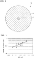
- An optical fiber 5 of the present embodiment includes, as shown in Fig. 1 , a core 1 which is provided at a center portion of the optical fiber 5 and a cladding 4 which surrounds an outer periphery of the core 1.
- the cladding 4 is typically cylindrical with respect to the core 1, the core 1 and the cladding 4 may be eccentric within the allowable range.
- the refractive index profile of the core is expressed by ⁇ (r) as a function of the relative refractive index difference ⁇ with respect to the distance r from the center of the core.
- the distance r is a non-negative (r ⁇ 0).
- the relative refractive index difference ⁇ of the core means a relative refractive index difference on the basis of a relative refractive index difference of the cladding. In the cladding, the relative refractive index difference is 0.
- a range of a value A determined by the following formula (defining formula of A) is identified as obtaining a low bending loss optical fiber. Derivation of the definition formula will be described later.
- A ⁇ ⁇ 0 0.22 MFD 1.31 ⁇ r ⁇ ⁇ ref r d r + ⁇ 0.22 MFD 1.31 0.44 MFD 1.31 ⁇ r ⁇ ⁇ ref r d r
- the unit of r is ⁇ m and the unit of the relative refractive index difference ⁇ (r) is %.
- ⁇ ref (r) is -0.064r + 0.494.
- MFD 1.31 is a mode field diameter at a wavelength of 1.31 ⁇ m.
- the MFD is not necessarily equal to the core diameter (diameter); however, generally, the MFD is approximately equals to the core diameter. Then, since 0.5MFD 1.31 is approximately equal to the core radius, a region of r ⁇ 0.44MFD 1.31 represents the most of the core (excluding a peripheral portion). A region of r ⁇ 0.22MFD 1.31 represents the center portion of the core.
- the definition expression of A described above includes a definite integral (first definite integral) in the interval of 0 ⁇ r ⁇ 0.22MFD 1.31 and a definite integral (second definite integral) in the interval of 0.22MFD1.31 ⁇ r ⁇ 0.44MFD 1.31 .
- first definite integral and the second of the definite integral each width of the integration interval (0.22MFD 1.31 ) is equal and the integrant ( ⁇ (r) - ⁇ ref (r)) is also equal; however, the signs are opposite and the contribution to A is different.
- the value A tends to be decreased.
- the value A is preferably equal to or less than 0.3 % ⁇ m.
- the value A is more preferably 0.2 % ⁇ m or less and is further more preferably 0.1 % ⁇ m or less.
- ⁇ ref (r) in the the definition formula of A represents a refractive index profile (reference refractive index profile) referred to by the definition formula of A.
- ⁇ ref (r) is represented by a linear formula of r.
- a ref (r) -0.064r + 0.494.
- the value A may be, for example, 0 % ⁇ m or more, -0.01 % ⁇ m or more, -0.02 % ⁇ m or more, -0.03 % ⁇ m or more, -0.05 % ⁇ m or more, -0.1 % ⁇ m or more, -0.2 % ⁇ m or more, -0.3 % ⁇ m or more, or the like.
- the method of manufacturing an optical fiber of the present embodiment includes calculating the value A using the defining formula of A and confirming that the value A is within a predetermined range (e.g., 0.3 % ⁇ m or less).
- the calculation step and the confirming step of A can be carried out at any stage in a series of steps either before or after each step which is carried out during manufacturing an optical fiber such as designing a refractive index profile of the optical fiber, manufacturing an optical fiber preform having the designed refractive index profile, drawing an optical fiber from the fiber preform and the like.
- the optical fiber according to the present embodiment is able to be manufactured by preparing an optical fiber preform by a known preform preparation method such as a vapor-phase axial deposition (VAD) method, an outside vapor deposition (OVD) method, and a chemical vapor deposition (CVD) method, and then, by drawing a optical fiber from the optical fiber preform.
- a known preform preparation method such as a vapor-phase axial deposition (VAD) method, an outside vapor deposition (OVD) method, and a chemical vapor deposition (CVD) method
- VAD vapor-phase axial deposition
- ODD outside vapor deposition
- CVD chemical vapor deposition
- the entire core or the entire core and a portion of the cladding can be manufactured by the VAD method as well as the remaining portion of the cladding can be manufactured by the OVD method.
- the size of the optical fiber is not particularly limited, and examples of the diameter of the clad include 125 ⁇ m, 80 ⁇ m, and the like.
- one or two or more layers of coating materials such as a resin may be laminated on the outer circumference of the cladding.
- the MFD be approximately the same as the MFD of the generic SM fiber.
- the mode field diameter MFD1.31 at a wavelength of 1.31 ⁇ m is preferably around 9.2 ⁇ m.
- the MFD1.31 be 9.2 ⁇ m ⁇ 0.2 ⁇ m or 8.93 ⁇ m or more and 9.4 ⁇ m or less.
- the refractive index profile of the core is preferably a single peak having only one peak in the range of the core diameter.
- having a single peak means that a point where the relative refractive index difference of the core is at maximum is only one point within the core diameter.
- the range of the core diameter includes, as a core center as 0, not only the side where the coordinate value of the radius is positive, but the side where the coordinate value of the radius is negative. If the refractive index profile of the core is concentric shape, the relative refractive index difference in the core center has a maximum value. Therefore, the maximum relative refractive index difference ⁇ max throughout the core and the maximum relative refractive index difference ⁇ c within the range where the distance r from the center of the core is 1 ⁇ m or less are preferably the same.
- the refractive index of the core may be higher than that of the cladding; however, if the relative refractive index difference is too small, the light confinement is weakened. Therefore, it is preferable that the maximum relative refractive index difference ⁇ max throughout the core be greater than 0.39 %. On the contrary, the required amount of dopants is increased and the cost increased when the relative refractive index difference is too large. Therefore, it is preferable that the maximum relative refractive index difference ⁇ max throughout the core be less than 0.50 %.
- a cut-off wavelength ⁇ cc (i.e., a cut-off wavelength ⁇ c 22m of 22 m) of the optical fiber is preferably 1260 nm or less. ⁇ cc may be 1170 nm or more. Furthermore, it is preferable that a MAC value represented by the ratio MFD 1.31 / ⁇ cc of the mode field diameter MFD 1.31 at a wavelength of 1.31 ⁇ m and a cable cut-off wavelength ⁇ cc be 7.38 or more and 7.7 or less.
- Examples of a dopant used for manufacturing a silica-based optical fiber include germanium (Ge), phosphorus (P), fluorine (F), boron (B), aluminum (Al), and the like. Two or more types of dopants may be used for manufacturing the silica-based optical fiber.
- a core material includes Ge added silica
- a cladding material includes pure silica.
- the first embodiment of the present invention has been described; however, the first embodiment is an example of the present invention, and addition, omission, substitution, and other changes are able to be performed without departing from the scope of the present invention.
- ⁇ cc ⁇ m/MFD ⁇ m is 1.20/9.00, 1.23/9.15, and 1.26/9.3, respectively.
- the variance value is adjusted by providing some low refractive index portions (depressed portions) in the cladding.
- a normalized electric field intensity profile in the reference refractive index profile is shown in Fig. 15 .
- An optical fiber including a core portion and a cladding layer provided around the core portion was manufactured.
- the optical fiber was manufactured by fiber drawing (drawing) an optical fiber preform.
- the optical fiber preform was manufactured in such a manner that after manufacturing a core member made of the entire core and a portion of the cladding with the VAD method or the CVD method, the remaining cladding layer was formed around the core member with the OVD method.
- the core preform was manufactured with the VAD method
- Example 9 the core preform was manufactured with the CVD method.
- the obtained refractive index profile of the optical fiber is represented by the relative refractive index difference ⁇ with respect to the radius ( ⁇ m).
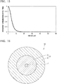
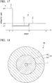
- the shape of the refractive index profile of the optical fiber of Examples 1-9 are shown in Figs. 3-11 .
- the core center is 0 ( ⁇ m) and the radius can have a positive or negative value.
- the distance r ( ⁇ m) from the core center in the definition formula of A is an absolute value of the radius ( ⁇ m), and is 0 or a positive value.
- Table 1 shows each parameter of the optical fiber of Examples 1-9.
- Table 1 ⁇ max [%] ⁇ c [%] r 1 [ ⁇ m] ⁇ min [%] A [%- ⁇ m] ⁇ cc [ ⁇ m] MFD 1.31 [ ⁇ m] MAC BENDING LOSS [dB/10 turns]
- EXAMPLE 1 0.41 0.41 4.5 -0.01 0.16 1.24 9.26 7.47 0. 017
- EXAMPLE 2 0.42 0.42 4.4 -0.04 0.
- ⁇ max is a maximum relative refractive index difference (%) in the entire core.
- ⁇ c is a maximum relative refractive index difference (%) within the range in which the distance r from the center core is 1 ⁇ m or less (i.e., -1 ⁇ m ⁇ radius ⁇ 1 ⁇ m).
- r 1 is the radius of the core ( ⁇ m).
- a region in which a distance r from the core center is greater than the core radius r1 is the cladding. In the cladding, the relative refractive index difference is 0.
- ⁇ min is a minimum relative refractive index difference (%) in the entire core.
- ⁇ cc is a cable cut-off wavelength ( ⁇ m).
- MFD 1.31 is a mode field diameter ( ⁇ m) at a wavelength of 1.31 ⁇ m.
- MAC represents a ratio value represented by MFD 1.31 / ⁇ cc.
- the bending loss represents a bending loss (dB/10 turns) at a bending radius of 15 mm and a wavelength of 1.55 ⁇ m.
- the optical fibers in Examples 1 to 9 had characteristics which comply with ITU-T Recommendation G.652.D. In this standard, it is determined that MFD 1.31 is 8.6-9.5 ⁇ m, the cladding diameter is 125.0 ⁇ 1 ⁇ m, the core eccentricity is 0.6 ⁇ m or less, the non-circularity of the cladding is 1.0% or less, the cable cut-off wavelength is 1260 nm or less, the macro bend loss (at a wavelength of 1625 nm, radius of 30mm, and 100 turns) is 0.1 dB or less, the zero-dispersion wavelength ⁇ is 1300 nm or more and 1324 nm or less, the zero-dispersion slope coefficient So is 0.092 ps/nm 2 ⁇ km or less.
- the value A (% ⁇ m) was determined.
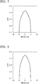
- the relationship between the value A and the bending loss (at the wavelength of 1.55 ⁇ m, the radius of 15 mm, and 10 turns) in Examples of 1-9 is shown in the graph of Fig. 1 . It has been found that as smaller the value A becomes, the smaller the value of the bending loss tends to be. In Table 1, Examples 1 to 6 and 9 correspond to A ⁇ 0.3 % ⁇ m.
- the bending loss was 0.034 dB/10 turn
- the mode field diameter MFD 1.31 was 9.2 ⁇ m
- the cable cut-off wavelength ⁇ cc was 1.20 ⁇ m.
- the cladding 4 may include the following configuration.
- Fig. 16 shows schematic configuration of an optical fiber 10 according to a second embodiment of the present invention.
- the optical fiber 10 includes a core 1 disposed on the center portion, and a cladding 4 disposed on the outer circumference side (the outer circumference) of the core 1 to be concentric with the core 1.
- the cladding 4 includes at least an inner cladding layer 2 adjacent to the outer circumference side of the core 1 and an outer cladding layer 3 formed on the outer circumference side of the inner cladding layer 2.
- Fig. 17 schematically shows a refractive index profile of the optical fiber 10.
- the refractive index of the core 1 is defined as ⁇ 1, and the maximum refractive index of the core 1 is defined as ⁇ 1max.
- the refractive index of the inner cladding layer 2 is defined as ⁇ 2, and the minimum refractive index of the inner cladding layer 2 is defined as ⁇ 2min.
- the refractive index of the outer cladding layer 3 is defined as ⁇ 3.
- the maximum refractive index ⁇ 1max of the core 1 is the refractive index of the core 1 which is maximized in a diameter direction range from the center of the core 1 to the outer circumference of the core 1.
- the refractive index ⁇ 1 of the core 1 is constant without depending on the position in the diameter direction, and thus, the refractive index ⁇ 1 is identical to the maximum refractive index ⁇ 1max in the entire range.
- the minimum refractive index ⁇ 2min of the inner cladding layer 2 is the refractive index of the inner cladding layer 2 which is minimized in a diameter direction range from the inner circumference of the inner cladding layer 2 to the outer circumference of the inner cladding layer 2.
- the refractive index ⁇ 2 of the inner cladding layer 2 is constant without depending on the position in the diameter direction, and thus, the refractive index ⁇ 2 is identical to the minimum refractive index ⁇ 2min in the entire range.
- the maximum refractive index ⁇ 1max of the core 1 is greater than the minimum refractive index ⁇ 2min of the inner cladding layer 2 and the refractive index ⁇ 3 of the outer cladding layer 3.
- the minimum refractive index ⁇ 2min of the inner cladding layer 2 is less than the refractive index ⁇ 3 of the outer cladding layer 3.
- Formula (12) indicates that the absolute value of a difference between the minimum refractive index ⁇ 2min of the inner cladding layer 2 and the refractive index ⁇ 3 of the outer cladding layer 3 is greater than 0.01% and less than 0.03%.
- the bending loss may not be sufficiently reduced.
- the absolute value of the difference between ⁇ 2min and ⁇ 3 is excessively small, the bending loss may not be sufficiently reduced.
- the absolute value of the difference between ⁇ 2min and ⁇ 3 is excessively large, the mode field diameter decreases, and a connection loss at the time of being connected to the other optical fiber (for example, a general single mode optical fiber (SSMF)) may increase.
- SSMF general single mode optical fiber
- the optical fiber 10 it is possible to reduce the bending loss by setting the absolute value of the difference between ⁇ 2min and ⁇ 3 to be greater than 0.01%.
- MFD mode field diameter
- Formula (11A) described below is satisfied with respect to a magnitude relationship of ⁇ 1max, ⁇ 2min, and ⁇ 3.
- the maximum refractive index ⁇ 1max of the core 1 is greater than the refractive index ⁇ 3 of the outer cladding layer 3.
- the refractive index ⁇ 3 of the outer cladding layer 3 is greater than the minimum refractive index ⁇ 2min of the inner cladding layer 2.
- ⁇ 3 is greater than ⁇ 2min, and thus, Formula (12) described above is able to be described as follows. 0.01 % ⁇ ⁇ 3 ⁇ ⁇ 2 min ⁇ 0.03 %
- Formula (12) indicates that a difference between the refractive index ⁇ 3 of the outer cladding layer 3 and the minimum refractive index ⁇ 2min of the inner cladding layer 2 is greater than 0.01% and less than 0.03%.
- the outer circumferential radii of the core 1, the inner cladding layer 2, and the outer cladding layer 3 are respectively described as r1, r2, and r3.
- the outer circumference radius r1 of the core 1, the outer circumferential radius r2 of the inner cladding layer 2, and the outer circumferential radius r3 of the outer cladding layer 3 have a relationship denoted by Formula (13) described below. r 1 ⁇ r 2 ⁇ r 3
- the ratio r1/r2 of the outer peripheral radius r2 of the inner cladding layer 2 and the outer peripheral radius r1 of the core 1 is in the range shown in the following Formula (14). 0.2 ⁇ r 1 / r 2 ⁇ 0.5
- the r1/r2 is 0.2 or more; thereby, optimizing the mode field diameter and the connection loss when connected to the other optical fiber can be reduced.
- r1/r2 is 0.5 or less, the bending loss can be reduced.
- the cable cutoff wavelength ⁇ cc is 1260 nm or less. In other words, the following Formula (15) is satisfied. ⁇ cc ⁇ 1260 nm
- the cut-off wavelength ⁇ cc is able to be measured by a measurement method disclosed in ITU-T Recommendation G.650.
- the refractive index and the outer circumferential radius described above are adjusted, and thus, the mode field diameter (MFD) at a wavelength of 1310 nm is greater than or equal to 8.6 ⁇ m and less than or equal to 9.5 ⁇ m. That is, Formula (16) described below is established. 8.6 ⁇ m ⁇ MFD ⁇ 9.5 ⁇ m
- the mode field diameter is in the range of Formula (16), and thus, the connection loss at the time of being connected to the other optical fiber (for example, SSMF) is able to be suppressed to be low.
- the mode field diameter is in the above range, and thus, the regulation of ITU-T G.652 is satisfied.
- a loss increase at a wavelength of 1550 nm at the time of winding the optical fiber 10 around a cylindrical mandrel having a diameter of 15 mm 10 times be less than or equal to 0.25 dB.
- the loss increase at a wavelength of 1625 nm at the time of winding the optical fiber 10 around the cylindrical mandrel having a diameter of 15 mm 10 times be less than or equal to 1.0 dB.
- the core 1, for example, is able to be configured of silica glass of which the refractive index increases by adding a dopant such as germanium (Ge).
- a dopant such as germanium (Ge).
- the inner cladding layer 2 for example, is able to be configured of silica glass of which the refractive index decreases by adding a dopant such as fluorine (F).
- the inner cladding layer 2, for example, may be configured of silica glass of which the refractive index increases by adding a dopant such as chlorine (Cl).
- the outer cladding layer 3 for example, is able to be configured of pure silica glass.
- the refractive index may be adjusted by adding a dopant (for example, Ge, F, and the like).
- Each layer configuring the optical fiber 10 is able to be formed by a known method such as a MCVD method, a PCVD method, a VAD method, and an OVD method, or a combination thereof.
- the optical fiber preform is able to be prepared as follows.
- a glass deposition layer which becomes the inner cladding layer 2 is formed on the inside of a silica glass tube (for example, a glass tube formed of pure silica glass) which becomes the outer cladding layer 3, for example, by using a raw material containing a dopant such as fluorine (F).
- a dopant such as fluorine (F).
- the refractive index of the inner cladding layer 2 is able to be adjusted by the added amount of the dopant.
- a glass deposition layer which becomes the core 1 is formed on the inside of the glass deposition layer, for example, by using a raw material containing a dopant such as germanium (Ge). Furthermore, the core 1 is able to be formed by using a core rod which is separately prepared.
- the silica glass tube in which the glass deposition layer is formed becomes the optical fiber preform through a transparency step, a solidification step, and the like.
- the optical fiber preform is subjected to fiber drawing, and thus, the optical fiber 10 shown in Fig. 16 is able to be obtained.
- the CVD method is preferable from the viewpoint of accurately adjusting the refractive index profile by adding a dopant.
- the VAD method and the OVD method are also able to be applied to manufacture the optical fiber 10.
- the VAD method and the OVD method have advantages such as high productivity.
- a difference in the refractive indices between the inner cladding layer 2 and the outer cladding layer 3 is in the range described above (refer to Formula (12)), and a ratio of the core 1 and the inner cladding layer 2 is in the range described above (refer to Formula (14)), and thus, the connection loss at the time of being connected to the other optical fiber is able to be suppressed to be low, and the bending loss is able to be reduced.
- the optical fiber 10 has technical meaning from the viewpoint of making suppression of the connection loss at the time of being connected to the other optical fiber and a reduction in the bending loss compatible.
- the difference in the refractive indices between the the inner cladding layer 2 and the outer cladding layer 3 is small, and thus, the refractive index of the inner cladding layer 2 and the outer cladding layer 3 is able to be easily and accurately adjusted by using the manufacturing method of the related art (for example, a general manufacturing method of SSMF) without considerably changing the method.
- the manufacturing method of the related art for example, a general manufacturing method of SSMF
- the difference in the refractive indices between the inner cladding layer 2 and the outer cladding layer 3 is small, and thus, constraint based on the manufacturing method decreases.
- the CVD method which is considered to be suitable for adjusting the refractive index profile, but also the VAD method, and the OVD method are able to be adopted.
- the optical fiber 10 is able to be easily manufactured, and manufacturing costs are able to be made low.
- the difference in the refractive indices between the inner cladding layer 2 and the outer cladding layer 3 is small, and thus, the added amount of the dopant such as fluorine (F) and chlorine (Cl) for forming the inner cladding layer 2 is able to be reduced.
- Raw material gas (for example, SiF 4 ) used in a dope such as fluorine (F) is expensive, and thus, raw material costs are able to be suppressed and manufacturing costs are able to be made low by reducing the added amount of the dopant.
- the minimum refractive index ⁇ 2min of the inner cladding layer 2 is less than the refractive index ⁇ 3 of the outer cladding layer 3, and thus, it is possible to make containment of the light with respect to the core 1 excellent and to reduce the bending loss.
- the optical fiber may further have the following configuration.
- Fig. 18 shows schematic configuration of an optical fiber 20 according to a second embodiment of the present invention.
- the optical fiber 20 includes a core 1 disposed on the center portion, and a cladding 14 disposed on the outer circumference side of the core 1 to be concentric with the core 1.
- the cladding 14 includes an inner cladding layer 12 adjacent to the outer circumference side of the core 1, and an outer cladding layer 13 formed on the outer circumference side of the inner cladding layer 12.
- Fig. 19 schematically shows a refractive index profile of the optical fiber 20.
- the refractive index of the core 1 is defined as ⁇ 1, and the maximum refractive index of the core 1 is defined as ⁇ 1max.
- the refractive index of the inner cladding layer 12 is defined as ⁇ 2, and the minimum refractive index of the inner cladding layer 12 is defined as ⁇ 2min.
- the refractive index of the outer cladding layer 13 is defined as ⁇ 3.
- the optical fiber 20 is different from the optical fiber 10 of the first embodiment in that the minimum refractive index ⁇ 2min of the inner cladding layer 12 is adjusted to be greater than the refractive index ⁇ 3 of the outer cladding layer 13.
- the absolute value of the difference between the ⁇ 2min and ⁇ 3 is adjusted to be in the range described above, and thus, the mode field diameter (MFD) is able to be optimized, the connection loss at the time of being connected to the other optical fiber is able to be suppressed to be low, and the bending loss is able to be reduced.
- MFD mode field diameter
- the outer circumference radius r1 of the core 1, the outer circumferential radius r2 of the inner cladding layer 12, and the outer circumferential radius r3 of the outer cladding layer 13 have relationships denoted by Formula (19) and Formula (20) described below, as with the optical fiber 10 of second embodiment.
- r1/r2 is adjusted to be 0.2 or more, and thus the mode field diameter is able to be optimized, the connection loss at the time of being connected to the other optical fiber is able to be suppressed to be low, and the bending loss is able to be reduced.
- the cut-off wavelength ⁇ cc is 1260 nm or less, as with the optical fiber 10 of the second embodiment.
- the mode field diameter (MFD) at a wavelength of 1310 nm is 8.6 ⁇ m or more and 9.5 ⁇ m or less.
- the loss increase at a wavelength of 1550 nm at the time of winding the optical fiber 10 around a cylindrical mandrel having a diameter of 15 mm 10 times be less than or equal to 0.25 dB.
- the loss increase at a wavelength of 1625 nm at the time of winding the optical fiber 10 around the cylindrical mandrel having a diameter of 15 mm 10 times be less than or equal to 1.0 dB.
- the core 1, for example, is able to be configured of silica glass of which the refractive index increases by adding a dopant such as germanium (Ge).
- a dopant such as germanium (Ge).
- the inner cladding layer 12 for example, is able to be configured of pure silica glass.
- the refractive index may be adjusted by adding a dopant such as chlorine (Cl).
- the outer cladding layer 13, for example, is able to be configured of pure silica glass.
- the outer cladding layer 3, for example, may be configured of silica glass of which the refractive index decreases by adding a dopant such as fluorine (F).
- the optical fiber 20 is able to be manufactured by such as a MCVD method, a PCVD method, a VAD method, and an OVD method as with the optical fiber 10 of the first embodiment.
- a MCVD method a PCVD method
- VAD method a VAD method
- OVD method an OVD method
- a glass deposition layer which becomes the inner cladding layer 12 is formed on the inside of a silica glass tube (for example, a silica glass tube containing a dopant such as fluorine (F)) which becomes the outer cladding layer 13 by using a raw material such as pure silica glass.
- a silica glass tube for example, a silica glass tube containing a dopant such as fluorine (F)
- F fluorine
- a glass deposition layer which becomes the core 1 is formed on the inside of the glass deposition layer, for example, by using a raw material containing a dopant such as germanium (Ge). Furthermore, the core 1 is able to be formed by using a core rod which is separately prepared.
- the silica glass tube in which the glass deposition layer is formed becomes the optical fiber preform through a transparency step, a solidification step, and the like.
- the optical fiber preform is subjected to fiber drawing, and thus, the optical fiber 20 shown in Fig. 18 is able to be obtained.
- a difference in the refractive indices between the inner cladding layer 12 and the outer cladding layer 13 is in the range described above, and a ratio of the core 1 and the inner cladding layer 12 is in the range described above, and thus, the connection loss at the time of being connected to the other optical fiber is able to be suppressed to be low, and the bending loss is able to be reduced.
- the manufacturing method of the related art is able to be used without being considerably changed, and thus, the optical fiber 20 is able to be easily manufactured, and the manufacturing costs are able to be made low.
- the claddings 4 and 14 are formed of two cladding layers (the inner cladding layer and the outer cladding layer), and the cladding may include layers other than the inner cladding layer and the outer cladding layer.
- the optical fiber may further have the following configuration.
- Fig. 20 shows a schematic configuration of an optical fiber 30 according to a fourth embodiment of the present invention.
- the optical fiber 30 includes a core 21 disposed on the center portion, and a cladding 25 disposed on the outer circumference side of the core 21 to be concentric with the core 21.
- the cladding 25 includes an inner cladding layer 22 adjacent to the outer circumference side of the core 21, a trench 23 formed to be adjacent to the outer circumference side of the inner cladding layer 22, and an outer cladding layer 24 formed on the outer circumference side of the trench 23.
- Fig. 21 schematically shows a refractive index profile of the optical fiber 30.
- the refractive index of the core 21 is defined as ⁇ 1, and the maximum refractive index of the core 21 is defined as ⁇ 1max.
- the refractive index of the inner cladding layer 22 is defined as ⁇ 2, and the minimum refractive index of the inner cladding layer 22 is defined as ⁇ 2min.
- the refractive index of the trench 23 is defined as ⁇ 3, and the minimum refractive index of the trench 23 is defined as ⁇ 3min.
- the refractive index of the outer cladding layer 24 is defined as ⁇ 4.
- the maximum refractive index ⁇ 1max of the core 21 is the refractive index of the core 21 which is maximized in a diameter direction range from the center of the core 21 to the outer circumference of the core 21.
- the refractive index ⁇ 1 of the core 21 is constant without depending on the position of the diameter direction, and thus, the refractive index ⁇ 1 is identical to the maximum refractive index ⁇ 1max in the entire range.
- the minimum refractive index ⁇ 2min of the inner cladding layer 22 is the refractive index of the inner cladding layer 22 which is minimized in a diameter direction range from the inner circumference of the inner cladding layer 22 to the outer circumference of the inner cladding layer 22.
- the refractive index ⁇ 2 of the inner cladding layer 22 is constant without depending on the position of the diameter direction, and thus, the refractive index ⁇ 2 is identical to the minimum refractive index ⁇ 2min in the entire range.
- the minimum refractive index ⁇ 3min of the trench 23 is the refractive index of the trench 23 which is minimized in a diameter direction range from the inner circumference of the trench 23 to the outer circumference of the trench 23.
- the refractive index ⁇ 3 of the trench 23 is constant without depending on the position of the diameter direction, and thus, the refractive index ⁇ 3 is identical to the minimum refractive index ⁇ 3min in the entire range.
- the maximum refractive index ⁇ 1max of the core 21 is greater than the refractive index ⁇ 2 of the inner cladding layer 22.
- the refractive index ⁇ 2 of the inner cladding layer 22 is greater than ⁇ 3min of the trench 23.
- the maximum refractive index ⁇ 1max of the core 21 is greater than the refractive index ⁇ 4 of the outer cladding layer 24.
- the refractive index ⁇ 4 of the outer cladding layer 24 is greater than ⁇ 3min of the trench 23.
- Formula (23) indicates that a difference between the refractive index ⁇ 4 of the outer cladding layer 24 and the minimum refractive index ⁇ 3min of the trench 23 is greater than 0.01% and less than 0.03%.
- the difference between ⁇ 4 and ⁇ 3min is excessively small, the bending loss may not be sufficiently reduced.
- the difference between ⁇ 4 and ⁇ 3min is excessively large, the mode field diameter decreases, and the connection loss at the time of being connected to the other optical fiber (for example, a general single mode optical fiber (SSMF)) may increase.
- SSMF single mode optical fiber
- the difference between ⁇ 4 and ⁇ 3min is in a range of greater than 0.01%, and thus, the bending loss is able to be reduced.
- the difference between ⁇ 4 and ⁇ 3min is less than 0.03%, and thus, the mode field diameter (MFD) is able to be optimized, and the connection loss at the time of being connected to the other optical fiber is able to be suppressed to be low.
- MFD mode field diameter
- the outer circumferential radii of the core 21, the inner cladding layer 22, the trench 23, and the outer cladding layer 24 are respectively r1, r2, r3, and r4.
- the outer circumference radius r1 of the core 21, the outer circumferential radius r2 of the inner cladding layer 22, the outer circumferential radius r3 of the trench 23, and the outer circumferential radius r4 of the outer cladding layer 24 have a relationship denoted by Formula (24) described below.
- a ratio r2/r1 of the outer circumferential radius r2 of the inner cladding layer 22 to the outer circumference radius r1 of the core 21 is in a range denoted by Formula (25) described below. 1 ⁇ r 2 / r 1 ⁇ 5
- r2/r1 When r2/r1 is excessively small, the bending loss may increase. In contrast, when r2/r1 is excessively large, the mode field diameter decreases, and the connection loss at the time of being connected to the other optical fiber (for example, SSMF) may increase.
- SSMF connection loss at the time of being connected to the other optical fiber
- r2/r1 is greater than or equal to 1, and thus, it is possible to reduce the bending loss.
- r2/r1 is less than or equal to 5, the mode field diameter is able to be optimized, and the connection loss at the time of being connected to the other optical fiber is able to be suppressed to be low.
- a ratio r3/r2 of the outer circumferential radius r3 of the trench 23 to the outer circumferential radius r2 of the inner cladding layer 22 is in a range denoted by Formula (26) described below. 1 ⁇ r 3 / r 2 ⁇ 2
- r3/r2 When r3/r2 is excessively small, the bending loss may increase. In contrast, when r3/r2 is excessively large, the mode field diameter decreases, and the connection loss at the time of being connected to the other optical fiber (for example, SSMF) may increase.
- SSMF connection loss at the time of being connected to the other optical fiber
- r3/r2 is greater than 1, and thus, it is possible to reduce the bending loss.
- r3/r2 is less than or equal to 2, and thus, the mode field diameter is able to be optimized, and the connection loss at the time of being connected to the other optical fiber is able to be suppressed to be low.
- the cut-off wavelength ⁇ cc is less than or equal to 1260 nm.
- the cut-off wavelength ⁇ cc is able to be measured by a measurement method disclosed in ITU-T Recommendation G.650.
- the refractive index and the outer circumferential radius described above are adjusted, and thus the mode field diameter (MFD) at a wavelength of 1310 nm is greater than or equal to 8.6 ⁇ m and less than or equal to 9.5 ⁇ m. That is, Formula (28) described below is established. 8.6 ⁇ m ⁇ MFD ⁇ 9.5 ⁇ m
- the mode field diameter is in the range of Formula (28), and thus, the connection loss at the time of being connected to the other optical fiber (for example, SSMF) is able to be suppressed to be low.
- the mode field diameter is in the range of Formula (28), and thus, the regulation of ITU-T G.652 is satisfied.
- the loss increase at a wavelength of 1550 nm at the time of winding the optical fiber 30 around a cylindrical mandrel having a diameter of 15 mm 10 times be less than or equal to 0.25 dB.
- the loss increase at a wavelength of 1625 nm at the time of winding the optical fiber 30 around the cylindrical mandrel having a diameter of 15 mm 10 times be less than or equal to 1.0 dB.
- the core 21, for example, is able to be configured of silica glass of which the refractive index increases by adding a dopant such as germanium (Ge).
- a dopant such as germanium (Ge).
- the inner cladding layer 22 and the trench 23, for example, are able to be configured of silica glass of which the refractive index decreases by adding a dopant such as fluorine (F).
- a dopant such as fluorine (F).
- the outer cladding layer 24, for example, is able to be configured of pure silica glass.
- the refractive index may be adjusted by adding a dopant (for example, Ge, F, and the like).
- Each layer configuring the optical fiber 30 is able to be formed by a known method such as a MCVD method, a PCVD method, a VAD method, and an OVD method, or a combination thereof.
- the optical fiber preform is able to be prepared as follows.
- a glass deposition layer which becomes the trench 23 is formed on the inside of the silica glass tube (for example, a glass tube formed of pure silica glass) which becomes the outer cladding layer 24, for example, by using a raw material containing a dopant such as fluorine (F).
- a dopant such as fluorine (F).
- a glass deposition layer which becomes the inner cladding layer 22 is formed on the inside of the glass deposition layer, for example, by using a raw material containing a dopant such as fluorine (F).
- a dopant such as fluorine (F).
- the refractive index of the trench 23 and the inner cladding layer 22 is able to be adjusted by the added amount of the dopant.
- a glass deposition layer which becomes the core 21 is formed on the inside of the glass deposition layer, for example, by using a raw material containing a dopant such as germanium (Ge). Furthermore, the core 21 is able to be formed by using a core rod which is separately prepared.
- the silica glass tube in which the glass deposition layer is formed becomes the optical fiber preform through a transparency step, a solidification step, and the like.
- the optical fiber preform is subjected to fiber drawing, and thus, the optical fiber 30 shown in Fig. 20 is able to be obtained.
- the CVD method is preferable from the viewpoint of accurately adjusting the refractive index profile by adding a dopant.
- the VAD method and the OVD method are also able to be applied to manufacture the optical fiber 30.
- the VAD method and the OVD method have advantages such as high productivity.
- a difference in the refractive indices between the trench 23 and the outer cladding layer 24 is in the range described above (refer to Formula (23)), and a ratio of the core 21, the inner cladding layer 22, and the the trench 23 is in the range described above (refer to Formula (25)-Formula (27)), and thus, the connection loss at the time of being connected to the other optical fiber is able to be suppressed to be low, and the bending loss is able to be reduced.
- the optical fiber 30 has technical meaning from the viewpoint of making suppression of the connection loss at the time of being connected to the other optical fiber and a reduction in the bending loss compatible.
- the difference in the refractive indices between the trench 23 and the outer cladding layer 24 is small, and thus, the refractive index of the trench 23 and the outer cladding layer 24 is able to be easily and accurately adjusted by using the manufacturing method of the related art (for example, a general manufacturing method of SSMF) without considerably changing the method.
- the manufacturing method of the related art for example, a general manufacturing method of SSMF
- the difference in the refractive indices between the trench 23 and the outer cladding layer 24 is small, and thus, constraint based on the manufacturing method decreases.
- the CVD method which is considered to be suitable for adjusting the refractive index profile
- the VAD method, and the OVD method are able to be adopted.
- the optical fiber 30 is able to be easily manufactured, and manufacturing costs are able to be made low.
- the difference in the refractive indices between the trench 23 and the outer cladding layer 24 is small, and thus, the added amount of the dopant such as fluorine (F) for forming the trench 23 is able to be reduced.
- Raw material gas (for example, SiF 4 ) used in a dope such as fluorine (F) is expensive, and thus, raw material costs are able to be suppressed and manufacturing costs are able to be made low by reducing the added amount of the dopant.
- the outer circumference radii r1 to r4 of the core 21, the inner cladding layer 22, the trench 23, and the outer cladding layer 24 have a relationship denoted by Formula (24). r 1 ⁇ r 2 ⁇ r 3 ⁇ r 4
- r1 is identical to r2, and thus, the cladding 25 is formed only of the trench 23 and the outer cladding layer 24 formed on the outer circumference side of the trench 23.
- the cladding 25 is formed of three layers (the inner cladding layer, the trench, and the outer cladding layer); however, the cladding may include other layers.
Landscapes
- Physics & Mathematics (AREA)
- General Physics & Mathematics (AREA)
- Optics & Photonics (AREA)
- Manufacture, Treatment Of Glass Fibers (AREA)
- Optical Fibers, Optical Fiber Cores, And Optical Fiber Bundles (AREA)
Abstract

Description
- The present invention relates to an optical fiber having low bending loss and a manufacturing method of the same.
- Priority is claimed on Japanese Patent Application No.
2014-195937, filed September 26, 2014 2014-195938, filed September 26, 2014 2014-249846, filed December 10, 2014 - An optical fiber having low bending loss (low bending loss optical fiber) is, in particular, needed for Fiber To The Home (FTTH) introducing an optical fiber to offices, homes, and the like. When drawing around the optical fiber inside of buildings and houses, for example, there is a possibility that a small bend is introduced to the optical fiber. A portion remaining after the drawing (extra portion) is stored by winding in a predetermined radius or more. By slightly bending the extra portion, the storage space can be reduced. Therefore, an optical fiber with a reduced so-called bending loss (macro bend loss) where the loss does not increase even when a small bend is introduced is important. In the optical fiber for home wiring, since the connection loss of the optical fiber connecting the base station and the home of user is small, the cost is required to be low. As an optical fiber connecting the base station and the home of user, since a distance is long, a general-purpose single-mode (SM) fiber is used.
- ITU-T Recommendation G.657 is used as the standard of an optical fiber in which the bending loss is reduced compared to a standard single mode optical fiber (SSMF) while being based on ITU-T Recommendation G.652 which is the standard of the standard single mode optical fiber (SSMF).
- Previously, in order to obtain a low bending loss optical fiber, for example, to reduce the mode field diameter (MFD) (e.g. see
Patent Documents example Patent documents 4 and 6) have been proposed. -
- [Patent Document 1] Japanese Patent No.
4268115 - [Patent Document 2] PCT International Publication No.
WO2006/016572 - [Patent Document 3] Japanese Unexamined Patent Application, First Publication No.
2013-88818 - [Patent Document 4] United States Patent No.
8428411 - [Patent Document 5] Japanese Unexamined Patent Application, First Publication No.
S63-43107 - [Patent Document 6] United States Patent No.
8588569 - [Non-Patent Document 1] K. Okamoto and T. Okoshi, "Computer-aided synthesis of the optimum refractive index profile for a multimode fiber," IEEE Trans. Microwave Theory Tech., vol. MTT-25, pp. 213-221, 1976
- As shown in
Fig. 2 ofPatent Document 1, when the MFD is reduced, a connection loss of an optical fiber with the general-purpose SM fiber is increased. For this reason, the MFD of the optical fiber is preferable to be the same as that of the general-purpose SM fiber (approximately 9.2 µm at a wavelength of 1.31 µm). - If the trench is provided around the core, without reducing the MFD, a low bending loss can be realized. However, when manufacturing the trench by an outside vapor deposition (OVD) method or a jacket of a glass with a low refractive index (e.g., quartz tube) and the like, the manufacturing process of the optical fiber increases. It is possible to manufacture from a core portion to a trench portion by the same inside vapor deposition (i.e., CVD) method; however, a size of a preform which can be manufactured is small, and an optical fiber which can be manufactured by drawing from one preform is short. As a result, the manufacturing cost increases in either way.
- From the above descriptions, it is desired that an optical fiber having a low bending loss has a refractive index profile with a single peak formed of a core and a cladding while maintaining the MFD equivalent to the MFD of a general-purpose optical fiber. Conventionally, it is known that when a refractive index profile of a core is an α-index profile, a bending loss decreases. Therefore, an optical fiber having a core refractive index profile in which the bending loss is lower than when having an α-index profile is required. In addition, even when a trench is provided around the core, an optical fiber having a core refractive index profile in which the bending loss is lower than when having an α-index profile is required.
- The present invention has been made in view of the above circumstances and provides an optical fiber having a core refractive index profile in which the bending loss is lower than when having an α-index profile and a method of manufacturing the same.
- A first aspect of the present invention is an optical fiber including a core and a cladding surrounding an outer periphery of the core and having a refractive index profile in which a relative refractive index difference with respect to a distance r from a center of the core is represented by Δ(r), where a value A represented by

- Here, the unit of r is µm, the unit of the relative refractive index difference Δ(r) is %, and Δref(r) = -0.064r + 0.494, and MFD1.31 is a mode field diameter at a wavelength of 1.31 µm.
- A second aspect of the present invention is the optical fiber according to the first aspect, in which the mode field diameter MFD1.31 at the wavelength of 1.31 µm is preferably 8.93 µm or more and 9.4 µm or less.
- A third aspect of the present invention is the optical fiber according to the first or second aspect, in which a maximum relative refractive index difference Δmax throughout the core and a maximum relative refractive index difference ΔC within a range where a distance r from a center of the core is 1 µm or less are preferably the same.
- A fourth aspect of the present invention is the optical fiber according to any one of the first to third aspects, in which a maximum relative refractive index difference Δmax throughout the core is 0.39% or more.
- A fifth aspect of the present invention is the optical fiber according to any one of the first to fourth aspects, in which a maximum relative refractive index difference Δmax throughout the core is 0.50% or less.
- A sixth aspect of the present invention is the optical fiber according to any one of the first to fifth aspects, in which a cable cut-off wavelength λcc is 1260 nm or less.
- A seventh aspect of the present invention is the optical fiber according to any one of the first to sixth aspects, in which a cable cut-off wavelength λcc is 1170 nm or less.
- A eighth aspect of the present invention is the optical fiber according to any one of the first to seventh aspects, in which a MAC value represented by a ratio MFD1.31/λcc of a mode field diameter MFD1.31 at a wavelength of 1.31 µm and a cable cut-off wavelength λcc is 7.38 or more and 7.7 or less.
- A ninth aspect of the present invention is a method of manufacturing the optical fiber according to any one of the first to eighth aspects having a refractive index profile in which a relative refractive index difference with respect to a distance r from a center of the core is represented by Δ(r), the method including, calculating a value A represented by

- According to the aspects of the present invention described above, an optical fiber having a greater relative refractive index difference at a position closer to a center of a core so that light is easily confined in the center of the core is obtained, and a loss when the optical fiber is bent can be reduced.
-
-
Fig. 1 is a cross-sectional view schematically showing an optical fiber according to the first embodiment of the present invention. -
Fig. 2 is a graph showing the relationship between a bending loss and an A value in an example of the first embodiment. -
Fig. 3 is a graph showing a refractive index profile of an optical fiber of Example 1. -
Fig. 4 is a graph showing a refractive index profile of an optical fiber of Example 2. -
Fig. 5 is a graph showing a refractive index profile of an optical fiber of Example 3. -
Fig. 6 is a graph showing a refractive index profile of an optical fiber of Example 4. -
Fig. 7 is a graph showing a refractive index profile of an optical fiber of Example 5. -
Fig. 8 is a graph showing a refractive index profile of an optical fiber of Example 6. -
Fig. 9 is a graph showing a refractive index profile of an optical fiber of Example 7. -
Fig. 10 is a graph showing a refractive index profile of an optical fiber of Example 8. -
Fig. 11 is a graph showing a refractive index profile of an optical fiber of Example 9. -
Fig. 12 is a drawing schematically showing a refractive index profile of the optical fiber according to the first embodiment of the present invention. -
Fig. 13A is a drawing schematically showing a refractive index profile used in a simulation. -
Fig. 13B is a drawing schematically showing a refractive index profile used in a simulation. -
Fig. 13C is a drawing schematically showing a refractive index profile used in a simulation. -
Fig. 14A is a drawing showing a calculation result of a bending loss. -
Fig. 14B is a drawing showing a calculation result of a bending loss. -
Fig. 14C is a drawing showing a calculation result of a bending loss. -
Fig. 15 is a drawing showing a standardized electric field profile in a reference refractive index profile. -
Fig. 16 is a cross-sectional view schematically showing an optical fiber according to the second embodiment of the present invention. -
Fig. 17 is a drawing schematically showing a refractive index profile of the optical fiber shown inFig. 16 . -
Fig. 18 is a cross-sectional view schematically showing an optical fiber according to the third embodiment of the present invention. -
Fig. 19 is a drawing schematically showing a refractive index profile of the optical fiber shown inFig. 18 . -
Fig. 20 is a cross-sectional view schematically showing an optical fiber according to the fourth embodiment of the present invention. -
Fig. 21 is a drawing schematically showing a refractive index profile of the optical fiber shown inFig. 20 . -
Fig. 22 is a drawing schematically showing a refractive index profile of the optical fiber according to another embodiment. - Hereinbelow, the first preferred embodiment of the present invention is described.
- An
optical fiber 5 of the present embodiment includes, as shown inFig. 1 , acore 1 which is provided at a center portion of theoptical fiber 5 and acladding 4 which surrounds an outer periphery of thecore 1. Although thecladding 4 is typically cylindrical with respect to thecore 1, thecore 1 and thecladding 4 may be eccentric within the allowable range. - The refractive index profile of the core is expressed by Δ(r) as a function of the relative refractive index difference Δ with respect to the distance r from the center of the core. The distance r is a non-negative (r ≥ 0). The relative refractive index difference Δ of the core means a relative refractive index difference on the basis of a relative refractive index difference of the cladding. In the cladding, the relative refractive index difference is 0. In the present embodiment, as a condition for obtaining a low bending loss optical fiber, a range of a value A determined by the following formula (defining formula of A) is identified. Derivation of the definition formula will be described later.

- Here, the unit of r is µm and the unit of the relative refractive index difference Δ(r) is %. Δref(r) is -0.064r + 0.494. MFD1.31 is a mode field diameter at a wavelength of 1.31 µm.
- In the SM fiber, the MFD is not necessarily equal to the core diameter (diameter); however, generally, the MFD is approximately equals to the core diameter. Then, since 0.5MFD1.31 is approximately equal to the core radius, a region of r ≤ 0.44MFD1.31 represents the most of the core (excluding a peripheral portion). A region of r ≤ 0.22MFD1.31 represents the center portion of the core.
- The definition expression of A described above includes a definite integral (first definite integral) in the interval of 0 ≤ r ≤ 0.22MFD1.31 and a definite integral (second definite integral) in the interval of 0.22MFD1.31 ≤ r ≤ 0.44MFD1.31. In the first definite integral and the second of the definite integral, each width of the integration interval (0.22MFD1.31) is equal and the integrant (Δ(r) - Δref(r)) is also equal; however, the signs are opposite and the contribution to A is different. As a result, in the refractive index profile in which the relative refractive index difference becomes higher when closer to the center portion of the core, the value A tends to be decreased.
- Therefore, the value A is preferably equal to or less than 0.3 %·µm. Thus, an optical fiber in which light is easily confined to the center of the core is obtained and it is possible to reduce the loss when the bent is occurred in the optical fiber. The value A is more preferably 0.2 %·µm or less and is further more preferably 0.1 %·µm or less.
- Δref(r) in the the definition formula of A represents a refractive index profile (reference refractive index profile) referred to by the definition formula of A. In the present embodiment, Δref(r) is represented by a linear formula of r. In particular, as described above, Aref(r) = -0.064r + 0.494. When the refractive index profile of the core is represented by Δ(r) = -0.064r + 0.494 as in the reference refractive index profile Aref(r), the integrant (Δ(r) - Δref(r)) in the definition formula of the A is identically 0; therefore, the value A is also 0. The value A may be, for example, 0 %·µm or more, -0.01 %·µm or more, -0.02 %·µm or more, -0.03 %·µm or more, -0.05 %·µm or more, -0.1 %·µm or more, -0.2 %·µm or more, -0.3 %·µm or more, or the like.
- The method of manufacturing an optical fiber of the present embodiment includes calculating the value A using the defining formula of A and confirming that the value A is within a predetermined range (e.g., 0.3 %·µm or less). The calculation step and the confirming step of A can be carried out at any stage in a series of steps either before or after each step which is carried out during manufacturing an optical fiber such as designing a refractive index profile of the optical fiber, manufacturing an optical fiber preform having the designed refractive index profile, drawing an optical fiber from the fiber preform and the like.
- The optical fiber according to the present embodiment is able to be manufactured by preparing an optical fiber preform by a known preform preparation method such as a vapor-phase axial deposition (VAD) method, an outside vapor deposition (OVD) method, and a chemical vapor deposition (CVD) method, and then, by drawing a optical fiber from the optical fiber preform. Examples of the preparation method of the optical fiber preform include a method in which glass configuring at least the core is prepared by an outside vapor deposition method or a chemical vapor deposition method, and a remaining glass portion is further prepared by deposition of silica (SiO2) glass, a jacket of a silica tube, and the like. More specifically, the entire core or the entire core and a portion of the cladding can be manufactured by the VAD method as well as the remaining portion of the cladding can be manufactured by the OVD method.
The size of the optical fiber is not particularly limited, and examples of the diameter of the clad include 125 µm, 80 µm, and the like. In the optical fiber after the drawing, one or two or more layers of coating materials such as a resin may be laminated on the outer circumference of the cladding. - It is often used in the optical fiber connecting the base station and the user's home, in order to suppress the connection loss with respect to the generic SM fiber which is used quite often as an optical fiber connecting the base station and the home of user, it is preferable that the MFD be approximately the same as the MFD of the generic SM fiber. For example, the mode field diameter MFD1.31 at a wavelength of 1.31 µm is preferably around 9.2 µm. Specifically, it is preferable that the MFD1.31 be 9.2 µm ± 0.2 µm or 8.93 µm or more and 9.4 µm or less.
- The refractive index profile of the core is preferably a single peak having only one peak in the range of the core diameter. Here, having a single peak means that a point where the relative refractive index difference of the core is at maximum is only one point within the core diameter. The range of the core diameter includes, as a core center as 0, not only the side where the coordinate value of the radius is positive, but the side where the coordinate value of the radius is negative. If the refractive index profile of the core is concentric shape, the relative refractive index difference in the core center has a maximum value. Therefore, the maximum relative refractive index difference Δmax throughout the core and the maximum relative refractive index difference Δc within the range where the distance r from the center of the core is 1 µm or less are preferably the same.
- In order to confine light in the core in the optical fiber, the refractive index of the core may be higher than that of the cladding; however, if the relative refractive index difference is too small, the light confinement is weakened. Therefore, it is preferable that the maximum relative refractive index difference Δmax throughout the core be greater than 0.39 %. On the contrary, the required amount of dopants is increased and the cost increased when the relative refractive index difference is too large. Therefore, it is preferable that the maximum relative refractive index difference Δmax throughout the core be less than 0.50 %.
- When the optical fiber is less influenced by the bending loss, the cut-off wavelength is shortened that is a lower limit of the wavelength range in which the single mode propagation is performed in the optical fiber, and the wavelength range of the single mode propagation is expanded. Therefore, a cut-off wavelength λcc (i.e., a cut-off wavelength λc22m of 22 m) of the optical fiber is preferably 1260 nm or less. λcc may be 1170 nm or more. Furthermore, it is preferable that a MAC value represented by the ratio MFD1.31/λcc of the mode field diameter MFD1.31 at a wavelength of 1.31 µm and a cable cut-off wavelength λcc be 7.38 or more and 7.7 or less.
- While the present invention has been described on the basis of the preferred embodiment above, the present invention is not limited to the above-mentioned embodiment but various modifications may be made without departing from the scope of the present invention.
- Examples of a dopant used for manufacturing a silica-based optical fiber include germanium (Ge), phosphorus (P), fluorine (F), boron (B), aluminum (Al), and the like. Two or more types of dopants may be used for manufacturing the silica-based optical fiber. In an example of the composition of the core and the cladding, a core material includes Ge added silica, and a cladding material includes pure silica.
- As described above, the first embodiment of the present invention has been described; however, the first embodiment is an example of the present invention, and addition, omission, substitution, and other changes are able to be performed without departing from the scope of the present invention.
- Hereinafter, detailed explanations of the present invention will be described with reference to the examples.
- First, in order to confirm the relationship between the core shape and the bending loss, although the core shape was different, a simulation was performed regarding a refractive index profile in which the cable cutoff wavelength was λcc and the MFD of the wavelength of 1.31 µm was constant. Characteristics were adjusted using the core diameter r1, the relative refractive index difference ΔC of the center core portion, and the relative refractive index difference Δ(r1) where the core diameter is r1 as variables (
Fig. 12 ). - The used refractive index profiles are shown in
Figs. 13A-13C . InFigs. 13A-13C , λcc µm/MFD µm is 1.20/9.00, 1.23/9.15, and 1.26/9.3, respectively. In addition, in order for a variance value to comply with ITU-T Recommendation G.652, depending on the refractive index profile, the variance value is adjusted by providing some low refractive index portions (depressed portions) in the cladding. - The calculation results of the bending loss of these refractive index profiles are shown in
Figs. 14A-14C . Based on the results, it can be seen that as greater the relative refractive index difference of the center core portion becomes (or as smaller the inclination of the core shape Δ(r1)/Δc becomes), the smaller the bending loss becomes. - However, the deviation occurs in the actual profile, and it is difficult to represent the bending loss using a relative refractive index difference of the center core portion or the inclination. Accordingly, it has been found that based on the deviation from the refractive index profile (reference refractive index profile) where the bending loss is the minimum in the simulation, the relationship with the bending loss is represented. In the standard refractive index profile, by using r1 = 5.45 µm, Δc=0.494 %, Δ(r1)=0.145 %, and Δ(r) = 0.064r + 0.494 (r≤5.45), the deviation is expressed as described below.

- A normalized electric field intensity profile in the reference refractive index profile is shown in
Fig. 15 . A radius at which the normalized electric field intensity is 0.5 is 4 µm at a location of approximately 0.44×MFD = β. It is considered that the confinement of light in the core center affects the bending loss; thus, the deviation is represented by a shape of an inner side of β. Also within this range, an inner peripheral portion (0 < r < α=β/12) and an outer peripheral portion (α=β/12 < r < β) is weighted. - An optical fiber including a core portion and a cladding layer provided around the core portion was manufactured. The optical fiber was manufactured by fiber drawing (drawing) an optical fiber preform. The optical fiber preform was manufactured in such a manner that after manufacturing a core member made of the entire core and a portion of the cladding with the VAD method or the CVD method, the remaining cladding layer was formed around the core member with the OVD method. In Examples 1-8, the core preform was manufactured with the VAD method, and in Example 9, the core preform was manufactured with the CVD method.
- The obtained refractive index profile of the optical fiber is represented by the relative refractive index difference Δ with respect to the radius (µm). The shape of the refractive index profile of the optical fiber of Examples 1-9 are shown in
Figs. 3-11 . In the graphs, regarding the radius (µm), the core center is 0 (µm) and the radius can have a positive or negative value. The distance r (µm) from the core center in the definition formula of A is an absolute value of the radius (µm), and is 0 or a positive value. - Table 1 shows each parameter of the optical fiber of Examples 1-9.
Table 1 Δmax [%] Δc [%] r1 [µm] Δmin [%] A [%-µm] λ cc [µm] MFD1.31 [µm] MAC BENDING LOSS [dB/10 turns] EXAMPLE 1 0.41 0.41 4.5 -0.01 0.16 1.24 9.26 7.47 0. 017 EXAMPLE 2 0.42 0.42 4.4 -0.04 0. 15 1.17 8.94 7.64 0.023 EXAMPLE 3 0.43 0.43 4.7 -0.02 0.10 1.25 9.28 7.42 0.007 EXAMPLE 4 0.45 0.45 4.6 -0.04 0.11 1.22 9.20 7.54 0.019 EXAMPLE 5 0.41 0.41 4.2 0 0.20 1.23 9.16 7.45 0.013 EXAMPLE 6 0.40 0.40 4.5 -0.01 0.21 1.21 9. 11 7.53 0.022 EXAMPLE 7 0.39 0.28 4.4 -0.01 0.35 1. 22 9.20 7.54 0.053 EXAMPLE 8 0.39 0.28 4.5 -0.01 0.36 1.23 9.24 7.51 0.040 EXAMPLE 9 0.49 0.49 5.5 0 0.00 1.23 9.17 7.46 0.007 - Δmax is a maximum relative refractive index difference (%) in the entire core. Δc is a maximum relative refractive index difference (%) within the range in which the distance r from the center core is 1 µm or less (i.e., -1 µm ≤ radius ≤ 1 µm). r1 is the radius of the core (µm). A region in which a distance r from the core center is greater than the core radius r1 is the cladding. In the cladding, the relative refractive index difference is 0. Δmin is a minimum relative refractive index difference (%) in the entire core.
- λcc is a cable cut-off wavelength (µm). MFD1.31 is a mode field diameter (µm) at a wavelength of 1.31 µm. MAC represents a ratio value represented by MFD1.31/λcc. The bending loss represents a bending loss (dB/10 turns) at a bending radius of 15 mm and a wavelength of 1.55 µm.
- The optical fibers in Examples 1 to 9 had characteristics which comply with ITU-T Recommendation G.652.D. In this standard, it is determined that MFD1.31 is 8.6-9.5 µm, the cladding diameter is 125.0±1 µm, the core eccentricity is 0.6 µm or less, the non-circularity of the cladding is 1.0% or less, the cable cut-off wavelength is 1260 nm or less, the macro bend loss (at a wavelength of 1625 nm, radius of 30mm, and 100 turns) is 0.1 dB or less, the zero-dispersion wavelength λα is 1300 nm or more and 1324 nm or less, the zero-dispersion slope coefficient So is 0.092 ps/nm2×km or less.
- Based on the definition formula of A, the value A (%·µm) was determined. The relationship between the value A and the bending loss (at the wavelength of 1.55 µm, the radius of 15 mm, and 10 turns) in Examples of 1-9 is shown in the graph of
Fig. 1 . It has been found that as smaller the value A becomes, the smaller the value of the bending loss tends to be. In Table 1, Examples 1 to 6 and 9 correspond to A ≤ 0.3 %·µm. - The broken line in
Fig. 1 shows a value of bending loss determined for the optical fiber having the refractive index profile of the α-th power (α = 3). In the optical fiber having the refractive index profile of the α-th power (α = 3), the bending loss was 0.034 dB/10 turn, the mode field diameter MFD1.31 was 9.2 µm, and the cable cut-off wavelength λcc was 1.20 µm. Based on these results, it has been found that by setting the value A to be 0.3 %·µm or less, an optical fiber having lower bending loss compared to the bending loss of an optical fiber having the refractive index profile of the α-th power (α = 3) can be obtained. - In the embodiment described above, the configuration such that the
optical fiber 5 includes thecore 1 and thecladding 4 is described; however, thecladding 4 may include the following configuration. -
Fig. 16 shows schematic configuration of anoptical fiber 10 according to a second embodiment of the present invention. - The
optical fiber 10 includes acore 1 disposed on the center portion, and acladding 4 disposed on the outer circumference side (the outer circumference) of thecore 1 to be concentric with thecore 1. - The
cladding 4 includes at least aninner cladding layer 2 adjacent to the outer circumference side of thecore 1 and anouter cladding layer 3 formed on the outer circumference side of theinner cladding layer 2. -
Fig. 17 schematically shows a refractive index profile of theoptical fiber 10. - The refractive index of the
core 1 is defined as Δ1, and the maximum refractive index of thecore 1 is defined as Δ1max. - The refractive index of the
inner cladding layer 2 is defined as Δ2, and the minimum refractive index of theinner cladding layer 2 is defined as Δ2min. - The refractive index of the
outer cladding layer 3 is defined as Δ3. - The maximum refractive index Δ1max of the
core 1 is the refractive index of thecore 1 which is maximized in a diameter direction range from the center of thecore 1 to the outer circumference of thecore 1. In the refractive index profile shown inFig. 17 , the refractive index Δ1 of thecore 1 is constant without depending on the position in the diameter direction, and thus, the refractive index Δ1 is identical to the maximum refractive index Δ1max in the entire range. - The minimum refractive index Δ2min of the
inner cladding layer 2 is the refractive index of theinner cladding layer 2 which is minimized in a diameter direction range from the inner circumference of theinner cladding layer 2 to the outer circumference of theinner cladding layer 2. In the refractive index profile shown inFig. 17 , the refractive index Δ2 of theinner cladding layer 2 is constant without depending on the position in the diameter direction, and thus, the refractive index Δ2 is identical to the minimum refractive index Δ2min in the entire range. - In the
optical fiber 10, the following formula (11) is satisfied.
- As shown in Formula (11), the maximum refractive index Δ1max of the
core 1 is greater than the minimum refractive index Δ2min of theinner cladding layer 2 and the refractive index Δ3 of theouter cladding layer 3. - In addition, in the
optical fiber 10, the minimum refractive index Δ2min of theinner cladding layer 2 is less than the refractive index Δ3 of theouter cladding layer 3. - In the
optical fiber 10, the following Formula (12) is further satisfied.
- Formula (12) indicates that the absolute value of a difference between the minimum refractive index Δ2min of the
inner cladding layer 2 and the refractive index Δ3 of theouter cladding layer 3 is greater than 0.01% and less than 0.03%. - When the absolute value of the difference between Δ2min and Δ3 is excessively small, the bending loss may not be sufficiently reduced. In contrast, when the absolute value of the difference between Δ2min and Δ3 is excessively large, the mode field diameter decreases, and a connection loss at the time of being connected to the other optical fiber (for example, a general single mode optical fiber (SSMF)) may increase.
- In the
optical fiber 10, it is possible to reduce the bending loss by setting the absolute value of the difference between Δ2min and Δ3 to be greater than 0.01%. In addition, it is possible to optimize the mode field diameter (MFD) and to suppress the connection loss to be low at the time of being connected to the other optical fiber by setting the absolute value of the difference between Δ2min and Δ3 to be less than 0.03%. - In the
optical fiber 10 of the first embodiment, Formula (11A) described below is satisfied with respect to a magnitude relationship of Δ1max, Δ2min, and Δ3.
- As shown in Formula (11A), the maximum refractive index Δ1max of the
core 1 is greater than the refractive index Δ3 of theouter cladding layer 3. - The refractive index Δ3 of the
outer cladding layer 3 is greater than the minimum refractive index Δ2min of theinner cladding layer 2. - Δ3 is greater than Δ2min, and thus, Formula (12) described above is able to be described as follows.

- Formula (12) indicates that a difference between the refractive index Δ3 of the
outer cladding layer 3 and the minimum refractive index Δ2min of theinner cladding layer 2 is greater than 0.01% and less than 0.03%. - The outer circumferential radii of the
core 1, theinner cladding layer 2, and theouter cladding layer 3 are respectively described as r1, r2, and r3. - The outer circumference radius r1 of the
core 1, the outer circumferential radius r2 of theinner cladding layer 2, and the outer circumferential radius r3 of theouter cladding layer 3 have a relationship denoted by Formula (13) described below.
- The ratio r1/r2 of the outer peripheral radius r2 of the
inner cladding layer 2 and the outer peripheral radius r1 of thecore 1 is in the range shown in the following Formula (14).
- When r1/r2 is too small, the mode field diameter is reduced, and the connection loss when connected to the other optical fiber (for example, S-SMF) may become larger. On the other hand, when r1/r2 is too large, there is a possibility that the bending loss increases.
- In the
optical fiber 10, the r1/r2 is 0.2 or more; thereby, optimizing the mode field diameter and the connection loss when connected to the other optical fiber can be reduced. When r1/r2 is 0.5 or less, the bending loss can be reduced. - In the
optical fiber 10, the cable cutoff wavelength λcc is 1260 nm or less. In other words, the following Formula (15) is satisfied.
- Accordingly, the regulation of ITU-T Recommendation G.652 is able to be satisfied.
- The cut-off wavelength λcc, for example, is able to be measured by a measurement method disclosed in ITU-T Recommendation G.650.
- In the
optical fiber 10, the refractive index and the outer circumferential radius described above are adjusted, and thus, the mode field diameter (MFD) at a wavelength of 1310 nm is greater than or equal to 8.6 µm and less than or equal to 9.5 µm. That is, Formula (16) described below is established.
- The mode field diameter is in the range of Formula (16), and thus, the connection loss at the time of being connected to the other optical fiber (for example, SSMF) is able to be suppressed to be low.
- In the
optical fiber 10, the mode field diameter is in the above range, and thus, the regulation of ITU-T G.652 is satisfied. - In the
optical fiber 10, it is preferable that a loss increase at a wavelength of 1550 nm at the time of winding theoptical fiber 10 around a cylindrical mandrel having a diameter of 15mm 10 times be less than or equal to 0.25 dB. - In addition, it is preferable that the loss increase at a wavelength of 1625 nm at the time of winding the
optical fiber 10 around the cylindrical mandrel having a diameter of 15mm 10 times be less than or equal to 1.0 dB. - The
core 1, for example, is able to be configured of silica glass of which the refractive index increases by adding a dopant such as germanium (Ge). - The
inner cladding layer 2, for example, is able to be configured of silica glass of which the refractive index decreases by adding a dopant such as fluorine (F). Theinner cladding layer 2, for example, may be configured of silica glass of which the refractive index increases by adding a dopant such as chlorine (Cl). - The
outer cladding layer 3, for example, is able to be configured of pure silica glass. In theouter cladding layer 3, the refractive index may be adjusted by adding a dopant (for example, Ge, F, and the like). - Each layer configuring the
optical fiber 10 is able to be formed by a known method such as a MCVD method, a PCVD method, a VAD method, and an OVD method, or a combination thereof. - For example, when the MCVD method is adopted, the optical fiber preform is able to be prepared as follows.
- A glass deposition layer which becomes the
inner cladding layer 2 is formed on the inside of a silica glass tube (for example, a glass tube formed of pure silica glass) which becomes theouter cladding layer 3, for example, by using a raw material containing a dopant such as fluorine (F). The refractive index of theinner cladding layer 2 is able to be adjusted by the added amount of the dopant. - Next, a glass deposition layer which becomes the
core 1 is formed on the inside of the glass deposition layer, for example, by using a raw material containing a dopant such as germanium (Ge). Furthermore, thecore 1 is able to be formed by using a core rod which is separately prepared. - The silica glass tube in which the glass deposition layer is formed becomes the optical fiber preform through a transparency step, a solidification step, and the like. The optical fiber preform is subjected to fiber drawing, and thus, the
optical fiber 10 shown inFig. 16 is able to be obtained. - The CVD method is preferable from the viewpoint of accurately adjusting the refractive index profile by adding a dopant.
- The VAD method and the OVD method are also able to be applied to manufacture the
optical fiber 10. The VAD method and the OVD method have advantages such as high productivity. - In the
optical fiber 10, a difference in the refractive indices between theinner cladding layer 2 and theouter cladding layer 3 is in the range described above (refer to Formula (12)), and a ratio of thecore 1 and theinner cladding layer 2 is in the range described above (refer to Formula (14)), and thus, the connection loss at the time of being connected to the other optical fiber is able to be suppressed to be low, and the bending loss is able to be reduced. - It has been known that the refractive index of the cladding in a portion close to the core considerably affects optical properties of the optical fiber; however, as a result of intensive studies of the present inventor, a refractive index profile has been found in which the bending loss is able to be reduced without decreasing the mode field diameter.
- By adopting the refractive index profile, the
optical fiber 10 has technical meaning from the viewpoint of making suppression of the connection loss at the time of being connected to the other optical fiber and a reduction in the bending loss compatible. - In the
optical fiber 10, the difference in the refractive indices between the theinner cladding layer 2 and theouter cladding layer 3 is small, and thus, the refractive index of theinner cladding layer 2 and theouter cladding layer 3 is able to be easily and accurately adjusted by using the manufacturing method of the related art (for example, a general manufacturing method of SSMF) without considerably changing the method. - In addition, the difference in the refractive indices between the
inner cladding layer 2 and theouter cladding layer 3 is small, and thus, constraint based on the manufacturing method decreases. For example, not only the CVD method which is considered to be suitable for adjusting the refractive index profile, but also the VAD method, and the OVD method are able to be adopted. - Accordingly, the
optical fiber 10 is able to be easily manufactured, and manufacturing costs are able to be made low. - In the
optical fiber 10, the difference in the refractive indices between theinner cladding layer 2 and theouter cladding layer 3 is small, and thus, the added amount of the dopant such as fluorine (F) and chlorine (Cl) for forming theinner cladding layer 2 is able to be reduced. - Raw material gas (for example, SiF4) used in a dope such as fluorine (F) is expensive, and thus, raw material costs are able to be suppressed and manufacturing costs are able to be made low by reducing the added amount of the dopant.
- As shown in
Fig. 17 , in theoptical fiber 10, the minimum refractive index Δ2min of theinner cladding layer 2 is less than the refractive index Δ3 of theouter cladding layer 3, and thus, it is possible to make containment of the light with respect to thecore 1 excellent and to reduce the bending loss. - In an embodiment of the present invention, the optical fiber may further have the following configuration.
-
Fig. 18 shows schematic configuration of anoptical fiber 20 according to a second embodiment of the present invention. - The
optical fiber 20 includes acore 1 disposed on the center portion, and acladding 14 disposed on the outer circumference side of thecore 1 to be concentric with thecore 1. - The
cladding 14 includes aninner cladding layer 12 adjacent to the outer circumference side of thecore 1, and anouter cladding layer 13 formed on the outer circumference side of theinner cladding layer 12. -
Fig. 19 schematically shows a refractive index profile of theoptical fiber 20. - The refractive index of the
core 1 is defined as Δ1, and the maximum refractive index of thecore 1 is defined as Δ1max. The refractive index of theinner cladding layer 12 is defined as Δ2, and the minimum refractive index of theinner cladding layer 12 is defined as Δ2min. The refractive index of theouter cladding layer 13 is defined as Δ3. - In the
optical fiber 20, Formula (17) described below is satisfied as with theoptical fiber 10 of the first embodiment.
- The
optical fiber 20 is different from theoptical fiber 10 of the first embodiment in that the minimum refractive index Δ2min of theinner cladding layer 12 is adjusted to be greater than the refractive index Δ3 of theouter cladding layer 13. - In the
optical fiber 20, Formula (18) described below is satisfied as with theoptical fiber 10 of the first embodiment.
- The absolute value of the difference between the Δ2min and Δ3 is adjusted to be in the range described above, and thus, the mode field diameter (MFD) is able to be optimized, the connection loss at the time of being connected to the other optical fiber is able to be suppressed to be low, and the bending loss is able to be reduced.
- The outer circumference radius r1 of the
core 1, the outer circumferential radius r2 of theinner cladding layer 12, and the outer circumferential radius r3 of theouter cladding layer 13 have relationships denoted by Formula (19) and Formula (20) described below, as with theoptical fiber 10 of second embodiment.

- r1/r2 is adjusted to be 0.2 or more, and thus the mode field diameter is able to be optimized, the connection loss at the time of being connected to the other optical fiber is able to be suppressed to be low, and the bending loss is able to be reduced.
- In the
optical fiber 20, the cut-off wavelength λcc is 1260 nm or less, as with theoptical fiber 10 of the second embodiment. - In addition, the mode field diameter (MFD) at a wavelength of 1310 nm is 8.6 µm or more and 9.5 µm or less.
- In the
optical fiber 20, it is preferable that the loss increase at a wavelength of 1550 nm at the time of winding theoptical fiber 10 around a cylindrical mandrel having a diameter of 15mm 10 times be less than or equal to 0.25 dB. In addition, it is preferable that the loss increase at a wavelength of 1625 nm at the time of winding theoptical fiber 10 around the cylindrical mandrel having a diameter of 15mm 10 times be less than or equal to 1.0 dB. - The
core 1, for example, is able to be configured of silica glass of which the refractive index increases by adding a dopant such as germanium (Ge). - The
inner cladding layer 12, for example, is able to be configured of pure silica glass. In theinner cladding layer 12, for example, the refractive index may be adjusted by adding a dopant such as chlorine (Cl). - The
outer cladding layer 13, for example, is able to be configured of pure silica glass. Theouter cladding layer 3, for example, may be configured of silica glass of which the refractive index decreases by adding a dopant such as fluorine (F). - The
optical fiber 20 is able to be manufactured by such as a MCVD method, a PCVD method, a VAD method, and an OVD method as with theoptical fiber 10 of the first embodiment. For example, when the MCVD method is adopted, the optical fiber preform is able to be prepared as follows. - A glass deposition layer which becomes the
inner cladding layer 12 is formed on the inside of a silica glass tube (for example, a silica glass tube containing a dopant such as fluorine (F)) which becomes theouter cladding layer 13 by using a raw material such as pure silica glass. - Next, a glass deposition layer which becomes the
core 1 is formed on the inside of the glass deposition layer, for example, by using a raw material containing a dopant such as germanium (Ge). Furthermore, thecore 1 is able to be formed by using a core rod which is separately prepared. - The silica glass tube in which the glass deposition layer is formed becomes the optical fiber preform through a transparency step, a solidification step, and the like. The optical fiber preform is subjected to fiber drawing, and thus, the
optical fiber 20 shown inFig. 18 is able to be obtained. - In the
optical fiber 20, a difference in the refractive indices between theinner cladding layer 12 and theouter cladding layer 13 is in the range described above, and a ratio of thecore 1 and theinner cladding layer 12 is in the range described above, and thus, the connection loss at the time of being connected to the other optical fiber is able to be suppressed to be low, and the bending loss is able to be reduced. - In the
optical fiber 20, the manufacturing method of the related art is able to be used without being considerably changed, and thus, theoptical fiber 20 is able to be easily manufactured, and the manufacturing costs are able to be made low. - As described above, the preferred embodiment of the present invention has been described; however, the embodiment is an example of the present invention, and addition, omission, substitution, and other changes are able to be performed without departing from the scope of the present invention.
- For example, in the
optical fibers Fig. 17 andFig. 19 , thecladdings - In an embodiment of the present invention, the optical fiber may further have the following configuration.
-
Fig. 20 shows a schematic configuration of anoptical fiber 30 according to a fourth embodiment of the present invention. - The
optical fiber 30 includes a core 21 disposed on the center portion, and acladding 25 disposed on the outer circumference side of the core 21 to be concentric with thecore 21. - The
cladding 25 includes aninner cladding layer 22 adjacent to the outer circumference side of the core 21, atrench 23 formed to be adjacent to the outer circumference side of theinner cladding layer 22, and anouter cladding layer 24 formed on the outer circumference side of thetrench 23. -
Fig. 21 schematically shows a refractive index profile of theoptical fiber 30. - The refractive index of the
core 21 is defined as Δ1, and the maximum refractive index of thecore 21 is defined as Δ1max. - The refractive index of the
inner cladding layer 22 is defined as Δ2, and the minimum refractive index of theinner cladding layer 22 is defined as Δ2min. - The refractive index of the
trench 23 is defined as Δ3, and the minimum refractive index of thetrench 23 is defined as Δ3min. - The refractive index of the
outer cladding layer 24 is defined as Δ4. - The maximum refractive index Δ1max of the
core 21 is the refractive index of the core 21 which is maximized in a diameter direction range from the center of the core 21 to the outer circumference of thecore 21. In the refractive index profile shown inFig. 21 , the refractive index Δ1 of thecore 21 is constant without depending on the position of the diameter direction, and thus, the refractive index Δ1 is identical to the maximum refractive index Δ1max in the entire range. - The minimum refractive index Δ2min of the
inner cladding layer 22 is the refractive index of theinner cladding layer 22 which is minimized in a diameter direction range from the inner circumference of theinner cladding layer 22 to the outer circumference of theinner cladding layer 22. In the refractive index profile shown inFig. 21 , the refractive index Δ2 of theinner cladding layer 22 is constant without depending on the position of the diameter direction, and thus, the refractive index Δ2 is identical to the minimum refractive index Δ2min in the entire range. - The minimum refractive index Δ3min of the
trench 23 is the refractive index of thetrench 23 which is minimized in a diameter direction range from the inner circumference of thetrench 23 to the outer circumference of thetrench 23. In the refractive index profile shown inFig. 21 , the refractive index Δ3 of thetrench 23 is constant without depending on the position of the diameter direction, and thus, the refractive index Δ3 is identical to the minimum refractive index Δ3min in the entire range. - In the
optical fiber 30, Formula (21) described below is satisfied.
- As shown in Formula (21), the maximum refractive index Δ1max of the
core 21 is greater than the refractive index Δ2 of theinner cladding layer 22. - The refractive index Δ2 of the
inner cladding layer 22 is greater than Δ3min of thetrench 23. - In the
optical fiber 30, Formula (22) described below is further satisfied.
- As shown in Formula (22), the maximum refractive index Δ1max of the
core 21 is greater than the refractive index Δ4 of theouter cladding layer 24. - The refractive index Δ4 of the
outer cladding layer 24 is greater than Δ3min of thetrench 23. - In the
optical fiber 30, Formula (23) described below is further established.
- Formula (23) indicates that a difference between the refractive index Δ4 of the
outer cladding layer 24 and the minimum refractive index Δ3min of thetrench 23 is greater than 0.01% and less than 0.03%. - When the difference between Δ4 and Δ3min is excessively small, the bending loss may not be sufficiently reduced. In contrast, the difference between Δ4 and Δ3min is excessively large, the mode field diameter decreases, and the connection loss at the time of being connected to the other optical fiber (for example, a general single mode optical fiber (SSMF)) may increase.
- In the
optical fiber 30, the difference between Δ4 and Δ3min is in a range of greater than 0.01%, and thus, the bending loss is able to be reduced. In addition, the difference between Δ4 and Δ3min is less than 0.03%, and thus, the mode field diameter (MFD) is able to be optimized, and the connection loss at the time of being connected to the other optical fiber is able to be suppressed to be low. - The outer circumferential radii of the core 21, the
inner cladding layer 22, thetrench 23, and theouter cladding layer 24 are respectively r1, r2, r3, and r4. - The outer circumference radius r1 of the core 21, the outer circumferential radius r2 of the
inner cladding layer 22, the outer circumferential radius r3 of thetrench 23, and the outer circumferential radius r4 of theouter cladding layer 24 have a relationship denoted by Formula (24) described below.
- A ratio r2/r1 of the outer circumferential radius r2 of the
inner cladding layer 22 to the outer circumference radius r1 of thecore 21 is in a range denoted by Formula (25) described below.
- When r2/r1 is excessively small, the bending loss may increase. In contrast, when r2/r1 is excessively large, the mode field diameter decreases, and the connection loss at the time of being connected to the other optical fiber (for example, SSMF) may increase.
- In the
optical fiber 30, r2/r1 is greater than or equal to 1, and thus, it is possible to reduce the bending loss. r2/r1 is less than or equal to 5, the mode field diameter is able to be optimized, and the connection loss at the time of being connected to the other optical fiber is able to be suppressed to be low. - A ratio r3/r2 of the outer circumferential radius r3 of the
trench 23 to the outer circumferential radius r2 of theinner cladding layer 22 is in a range denoted by Formula (26) described below.
- When r3/r2 is excessively small, the bending loss may increase. In contrast, when r3/r2 is excessively large, the mode field diameter decreases, and the connection loss at the time of being connected to the other optical fiber (for example, SSMF) may increase.
- In the
optical fiber 30, r3/r2 is greater than 1, and thus, it is possible to reduce the bending loss. r3/r2 is less than or equal to 2, and thus, the mode field diameter is able to be optimized, and the connection loss at the time of being connected to the other optical fiber is able to be suppressed to be low. - In the
optical fiber 30, the cut-off wavelength λcc is less than or equal to 1260 nm. - That is, Formula (27) described below is satisfied.

- Accordingly, the regulation of ITU-T Recommendation G.652 is able to be satisfied.
- The cut-off wavelength λcc, for example, is able to be measured by a measurement method disclosed in ITU-T Recommendation G.650.
- In the
optical fiber 30, the refractive index and the outer circumferential radius described above are adjusted, and thus the mode field diameter (MFD) at a wavelength of 1310 nm is greater than or equal to 8.6 µm and less than or equal to 9.5 µm. That is, Formula (28) described below is established.
- The mode field diameter is in the range of Formula (28), and thus, the connection loss at the time of being connected to the other optical fiber (for example, SSMF) is able to be suppressed to be low.
- In the
optical fiber 30, the mode field diameter is in the range of Formula (28), and thus, the regulation of ITU-T G.652 is satisfied. - In the
optical fiber 30, it is preferable that the loss increase at a wavelength of 1550 nm at the time of winding theoptical fiber 30 around a cylindrical mandrel having a diameter of 15mm 10 times be less than or equal to 0.25 dB. - In addition, it is preferable that the loss increase at a wavelength of 1625 nm at the time of winding the
optical fiber 30 around the cylindrical mandrel having a diameter of 15mm 10 times be less than or equal to 1.0 dB. - The
core 21, for example, is able to be configured of silica glass of which the refractive index increases by adding a dopant such as germanium (Ge). - The
inner cladding layer 22 and thetrench 23, for example, are able to be configured of silica glass of which the refractive index decreases by adding a dopant such as fluorine (F). - The
outer cladding layer 24, for example, is able to be configured of pure silica glass. In theouter cladding layer 24, the refractive index may be adjusted by adding a dopant (for example, Ge, F, and the like). - Each layer configuring the
optical fiber 30 is able to be formed by a known method such as a MCVD method, a PCVD method, a VAD method, and an OVD method, or a combination thereof. - For example, when the MCVD method is adopted, the optical fiber preform is able to be prepared as follows.
- A glass deposition layer which becomes the
trench 23 is formed on the inside of the silica glass tube (for example, a glass tube formed of pure silica glass) which becomes theouter cladding layer 24, for example, by using a raw material containing a dopant such as fluorine (F). - A glass deposition layer which becomes the
inner cladding layer 22 is formed on the inside of the glass deposition layer, for example, by using a raw material containing a dopant such as fluorine (F). - The refractive index of the
trench 23 and theinner cladding layer 22 is able to be adjusted by the added amount of the dopant. - Next, a glass deposition layer which becomes the core 21 is formed on the inside of the glass deposition layer, for example, by using a raw material containing a dopant such as germanium (Ge). Furthermore, the
core 21 is able to be formed by using a core rod which is separately prepared. - The silica glass tube in which the glass deposition layer is formed becomes the optical fiber preform through a transparency step, a solidification step, and the like. The optical fiber preform is subjected to fiber drawing, and thus, the
optical fiber 30 shown inFig. 20 is able to be obtained. - The CVD method is preferable from the viewpoint of accurately adjusting the refractive index profile by adding a dopant.
- The VAD method and the OVD method are also able to be applied to manufacture the
optical fiber 30. The VAD method and the OVD method have advantages such as high productivity. - In the
optical fiber 30, a difference in the refractive indices between thetrench 23 and theouter cladding layer 24 is in the range described above (refer to Formula (23)), and a ratio of the core 21, theinner cladding layer 22, and the thetrench 23 is in the range described above (refer to Formula (25)-Formula (27)), and thus, the connection loss at the time of being connected to the other optical fiber is able to be suppressed to be low, and the bending loss is able to be reduced. - It has been known that the refractive index of the cladding in a portion close to the core considerably affects optical properties of the optical fiber; however, as a result of intensive studies of the present inventor, a refractive index profile has been found in which the bending loss is able to be reduced without decreasing the mode field diameter.
- By adopting the refractive index profile, the
optical fiber 30 has technical meaning from the viewpoint of making suppression of the connection loss at the time of being connected to the other optical fiber and a reduction in the bending loss compatible. - In the
optical fiber 30, the difference in the refractive indices between thetrench 23 and theouter cladding layer 24 is small, and thus, the refractive index of thetrench 23 and theouter cladding layer 24 is able to be easily and accurately adjusted by using the manufacturing method of the related art (for example, a general manufacturing method of SSMF) without considerably changing the method. - In addition, the difference in the refractive indices between the
trench 23 and theouter cladding layer 24 is small, and thus, constraint based on the manufacturing method decreases. For example, not only the CVD method which is considered to be suitable for adjusting the refractive index profile, but also the VAD method, and the OVD method are able to be adopted. - Accordingly, the
optical fiber 30 is able to be easily manufactured, and manufacturing costs are able to be made low. - In the
optical fiber 30, the difference in the refractive indices between thetrench 23 and theouter cladding layer 24 is small, and thus, the added amount of the dopant such as fluorine (F) for forming thetrench 23 is able to be reduced. - Raw material gas (for example, SiF4) used in a dope such as fluorine (F) is expensive, and thus, raw material costs are able to be suppressed and manufacturing costs are able to be made low by reducing the added amount of the dopant.
- As described above, the outer circumference radii r1 to r4 of the core 21, the
inner cladding layer 22, thetrench 23, and theouter cladding layer 24 have a relationship denoted by Formula (24).
- In the
optical fiber 30 shown inFigs. 20 and21 , r1, r2, and r3 are values different from each other; however, the present invention includes a case of r1 = r2 and r2 ≠ r3. -
Fig. 22 is a diagram of a refractive index profile of an optical fiber of another embodiment of the present invention, and shows a case of r1 = r2 and r2 ≠ r3. - In the optical fiber, r1 is identical to r2, and thus, the
cladding 25 is formed only of thetrench 23 and theouter cladding layer 24 formed on the outer circumference side of thetrench 23. - As described above, the preferred embodiment of the present invention has been described; however, the embodiment is an example of the present invention, and addition, omission, substitution, and other changes are able to be performed without departing from the scope of the present invention.
- For example, in the
optical fiber 30 shown inFig. 20 , thecladding 25 is formed of three layers (the inner cladding layer, the trench, and the outer cladding layer); however, the cladding may include other layers. -
- 1,5,21:
- core
- 2, 12, 22:
- the inner cladding layer
- 3, 13, 24:
- external cladding layer
- 4, 14:
- clad
- 23:
- trench section
- 10, 20, 30:
- optical fiber
- Δ:
- the relative refractive index difference
Claims (9)
- An optical fiber comprising a core and a cladding surrounding an outer periphery of the core and having a refractive index profile in which a relative refractive index difference with respect to a distance r from a center of the core is represented by Δ(r), wherein a value A represented by

where a unit of r is µm, a unit of a relative refractive index difference Δ(r) is %, Δref(r) = -0.064r+0.494, and MFD1.31 is a mode field diameter at a wavelength of 1.31 µm. - The optical fiber according to claim 1, wherein the mode field diameter at the wavelength of 1.31 µm is 8.93 µm or more and 9.4 µm or less.
- The optical fiber according to claim 1 or 2, wherein a maximum relative refractive index difference Δmax throughout the core and a maximum relative refractive index difference Δc within a range where a distance r from a center of the core is 1 µm or less are the same.
- The optical fiber according to any one of claims 1 to 3, wherein a maximum relative refractive index difference Δmax throughout the core is 0.39% or more.
- The optical fiber according to any one of claims 1 to 4, wherein a maximum relative refractive index difference Δmax throughout the core is 0.50% or less.
- The optical fiber according to any one of claims 1 to 5, wherein a cable cut-off wavelength λcc is 1260 nm or less.
- The optical fiber according to any one of claims 1 to 6, wherein a cable cut-off wavelength λcc is 1170 nm or less.
- The optical fiber according to any one of claims 1 to 7, wherein a MAC value represented by a ratio MFD1.31/λcc of a mode field diameter MFD1.31 at a wavelength of 1.31 µm and a cable cut-off wavelength λcc is 7.38 or more and 7.7 or less.
- A method of manufacturing the optical fiber according to any one of claims 1 to 8 having a refractive index profile in which a relative refractive index difference with respect to a distance r from a center of the core is represented by Δ(r), the method comprising:calculating a value A represented by

Applications Claiming Priority (4)
| Application Number | Priority Date | Filing Date | Title |
|---|---|---|---|
| JP2014195937 | 2014-09-26 | ||
| JP2014195938 | 2014-09-26 | ||
| JP2014249846 | 2014-12-10 | ||
| PCT/JP2015/076899 WO2016047675A1 (en) | 2014-09-26 | 2015-09-24 | Optical fiber and method for manufacturing same |
Publications (2)
| Publication Number | Publication Date |
|---|---|
| EP3199992A1 true EP3199992A1 (en) | 2017-08-02 |
| EP3199992A4 EP3199992A4 (en) | 2018-06-27 |
Family
ID=55581198
Family Applications (1)
| Application Number | Title | Priority Date | Filing Date |
|---|---|---|---|
| EP15844942.1A Ceased EP3199992A4 (en) | 2014-09-26 | 2015-09-24 | Optical fiber and method for manufacturing same |
Country Status (5)
| Country | Link |
|---|---|
| US (1) | US10067287B2 (en) |
| EP (1) | EP3199992A4 (en) |
| JP (1) | JP6393338B2 (en) |
| CN (1) | CN106716198B (en) |
| WO (1) | WO2016047675A1 (en) |
Cited By (1)
| Publication number | Priority date | Publication date | Assignee | Title |
|---|---|---|---|---|
| EP4394462A1 (en) * | 2022-12-30 | 2024-07-03 | Sterlite Technologies Limited | Optical fiber with a fluorine cladding adjacent to the core |
Families Citing this family (7)
| Publication number | Priority date | Publication date | Assignee | Title |
|---|---|---|---|---|
| EP3488274B1 (en) * | 2016-07-20 | 2023-05-03 | University of Rochester | Lma fibers for suppression of thermal mode instability |
| JP6911307B2 (en) * | 2016-09-13 | 2021-07-28 | 住友電気工業株式会社 | Optical fiber and optical fiber core wire |
| EP3754393A4 (en) * | 2018-02-13 | 2021-10-20 | Fujikura, Ltd. | Optical fiber |
| US11714227B2 (en) * | 2019-06-17 | 2023-08-01 | Sterlite Technologies Limited | Universal optical fiber |
| AU2021365910B2 (en) * | 2020-10-19 | 2024-08-01 | Fujikura Ltd. | Optical fiber cable |
| CN115128728B (en) * | 2022-06-01 | 2023-09-26 | 长飞光纤光缆股份有限公司 | Distributed acoustic vibration sensing optical fiber and acoustic vibration monitoring system |
| US12353002B2 (en) * | 2022-12-22 | 2025-07-08 | Sterlite Technologies Limited | Optical fiber with improved microbending performance |
Family Cites Families (36)
| Publication number | Priority date | Publication date | Assignee | Title |
|---|---|---|---|---|
| US4852968A (en) | 1986-08-08 | 1989-08-01 | American Telephone And Telegraph Company, At&T Bell Laboratories | Optical fiber comprising a refractive index trench |
| US5504829A (en) | 1993-12-27 | 1996-04-02 | Corning Incorporated | Optical fiber for soliton transmission and method of making |
| CA2314961C (en) | 1997-12-30 | 2005-08-09 | Ji-Hoon Lee | Dispersion shifted optical fiber |
| JP3437484B2 (en) | 1999-03-19 | 2003-08-18 | 信越化学工業株式会社 | Method and apparatus for manufacturing optical fiber preform |
| EP1364919B1 (en) | 1998-11-05 | 2008-02-13 | Shin-Etsu Chemical Co., Ltd. | Method for manufacturing a preform and optical fibre from the preform |
| JP2000205999A (en) | 1999-01-08 | 2000-07-28 | Fujikura Ltd | Optical fiber measuring device |
| NL1018338C2 (en) | 2001-06-20 | 2002-12-30 | Draka Fibre Technology Bv | Optical fiber. |
| JP3986842B2 (en) | 2001-07-26 | 2007-10-03 | 株式会社フジクラ | Manufacturing method of optical fiber preform for non-zero dispersion shifted optical fiber |
| KR100419418B1 (en) | 2002-04-03 | 2004-02-21 | 삼성전자주식회사 | Dispersion-controlled fiber |
| KR100506311B1 (en) | 2003-01-20 | 2005-08-05 | 삼성전자주식회사 | Wide-band dispersion controlled optical fiber |
| JP3854627B2 (en) | 2003-04-17 | 2006-12-06 | 日本電信電話株式会社 | Single-mode optical fiber with holes |
| CN100476469C (en) | 2004-04-28 | 2009-04-08 | Ls电线有限公司 | Optical fiber with improved bending performance |
| EP1777559A4 (en) | 2004-08-10 | 2010-03-24 | Fujikura Ltd | Single-mode optical fiber |
| EP2348344B1 (en) | 2004-08-30 | 2013-02-20 | Fujikura Ltd. | Single-mode optical fiber |
| JP4268115B2 (en) | 2004-10-28 | 2009-05-27 | 古河電気工業株式会社 | Single mode optical fiber |
| JP4101227B2 (en) | 2004-11-05 | 2008-06-18 | 古河電気工業株式会社 | Optical fiber and optical fiber manufacturing method used therefor |
| CN100545686C (en) * | 2004-11-05 | 2009-09-30 | 株式会社藤仓 | Optical fiber and transmission system and wavelength division multiplexing transmission system |
| JPWO2006049279A1 (en) | 2004-11-05 | 2008-05-29 | 株式会社フジクラ | Optical fiber and transmission system and wavelength division multiplexing transmission system |
| KR100668284B1 (en) | 2004-12-14 | 2007-01-16 | 한국전자통신연구원 | Distributed Compensation Fiber for S-band Isolated Raman Amplifier |
| JP4417286B2 (en) | 2005-04-13 | 2010-02-17 | 日本電信電話株式会社 | Holey fiber and fiber optic modules |
| KR100635688B1 (en) * | 2005-04-29 | 2006-10-17 | 엘에스전선 주식회사 | Optical fiber with improved induced Brillouin scattering threshold, optical transmission line and optical communication system using same |
| JP5410750B2 (en) * | 2005-06-15 | 2014-02-05 | コーニング インコーポレイテッド | High SBS threshold optical fiber containing aluminum dopant |
| US7764854B2 (en) | 2005-12-27 | 2010-07-27 | Ofs Fitel Llc | Optical fiber with specialized index profile to compensate for bend-induced distortions |
| US7406237B2 (en) | 2006-02-21 | 2008-07-29 | Corning Incorporated | Multiband optical fiber |
| US7505660B2 (en) | 2006-06-30 | 2009-03-17 | Corning Incorporated | Microstructured transmission optical fiber |
| US20080050086A1 (en) | 2006-08-24 | 2008-02-28 | Scott Robertson Bickham | Optical fiber containing alkali metal oxide |
| US7689085B1 (en) | 2009-01-30 | 2010-03-30 | Corning Incorporated | Large effective area fiber with GE-free core |
| US7876990B1 (en) * | 2009-11-25 | 2011-01-25 | Corning Incorporated | Low loss optical fiber |
| US8542969B2 (en) | 2010-02-26 | 2013-09-24 | Corning Incorporated | Low bend loss optical fiber |
| EP2369379B1 (en) | 2010-03-17 | 2015-05-06 | Draka Comteq B.V. | Fibre optique monomode ayant des pertes par courbures réduites |
| US9279935B2 (en) | 2010-12-23 | 2016-03-08 | Prysmian S.P.A. | Low macrobending loss single-mode optical fibre |
| KR102038955B1 (en) | 2011-08-19 | 2019-10-31 | 코닝 인코포레이티드 | Low bend loss optical fiber |
| KR101273801B1 (en) | 2011-10-17 | 2013-06-11 | 에쓰이에이치에프코리아 (주) | Extreme bend insensitive fiber |
| US8588569B2 (en) | 2011-11-30 | 2013-11-19 | Corning Incorporated | Low bend loss optical fiber |
| JP6361101B2 (en) | 2012-09-04 | 2018-07-25 | 住友電気工業株式会社 | Optical fiber |
| US9383511B2 (en) | 2013-05-02 | 2016-07-05 | Corning Incorporated | Optical fiber with large mode field diameter and low microbending losses |
-
2015
- 2015-09-24 CN CN201580051121.1A patent/CN106716198B/en active Active
- 2015-09-24 EP EP15844942.1A patent/EP3199992A4/en not_active Ceased
- 2015-09-24 US US15/514,090 patent/US10067287B2/en active Active
- 2015-09-24 WO PCT/JP2015/076899 patent/WO2016047675A1/en not_active Ceased
- 2015-09-24 JP JP2016550352A patent/JP6393338B2/en active Active
Cited By (1)
| Publication number | Priority date | Publication date | Assignee | Title |
|---|---|---|---|---|
| EP4394462A1 (en) * | 2022-12-30 | 2024-07-03 | Sterlite Technologies Limited | Optical fiber with a fluorine cladding adjacent to the core |
Also Published As
| Publication number | Publication date |
|---|---|
| JP6393338B2 (en) | 2018-09-19 |
| CN106716198A (en) | 2017-05-24 |
| WO2016047675A1 (en) | 2016-03-31 |
| US20170336558A1 (en) | 2017-11-23 |
| JPWO2016047675A1 (en) | 2017-06-01 |
| US10067287B2 (en) | 2018-09-04 |
| CN106716198B (en) | 2019-06-21 |
| EP3199992A4 (en) | 2018-06-27 |
Similar Documents
| Publication | Publication Date | Title |
|---|---|---|
| US10067287B2 (en) | Optical fiber and method of manufacturing the same | |
| JP7094915B2 (en) | Optical fiber | |
| JP5820377B2 (en) | Low bending loss optical fiber | |
| JP6155380B2 (en) | Optical fiber and manufacturing method thereof | |
| JP3853833B2 (en) | Optical fiber | |
| KR101908735B1 (en) | Single mode optical fiber | |
| JP6298893B2 (en) | Single mode fiber with trapezoidal core showing reduced loss | |
| CN111512200B (en) | Bend loss insensitive single mode optical fiber with shallow trench and corresponding optical system | |
| CN103635840B (en) | Multimode optical fiber and system comprising same | |
| EP3922612B1 (en) | OPTICAL FIBER | |
| EP3657223B1 (en) | Optical fiber and method for producing same | |
| EP3896038B1 (en) | Optical fiber | |
| US11714228B2 (en) | Optical fiber and method of manufacturing optical fiber | |
| WO2023112968A1 (en) | Optical fiber |
Legal Events
| Date | Code | Title | Description |
|---|---|---|---|
| STAA | Information on the status of an ep patent application or granted ep patent |
Free format text: STATUS: THE INTERNATIONAL PUBLICATION HAS BEEN MADE |
|
| PUAI | Public reference made under article 153(3) epc to a published international application that has entered the european phase |
Free format text: ORIGINAL CODE: 0009012 |
|
| STAA | Information on the status of an ep patent application or granted ep patent |
Free format text: STATUS: REQUEST FOR EXAMINATION WAS MADE |
|
| 17P | Request for examination filed |
Effective date: 20170328 |
|
| AK | Designated contracting states |
Kind code of ref document: A1 Designated state(s): AL AT BE BG CH CY CZ DE DK EE ES FI FR GB GR HR HU IE IS IT LI LT LU LV MC MK MT NL NO PL PT RO RS SE SI SK SM TR |
|
| AX | Request for extension of the european patent |
Extension state: BA ME |
|
| DAV | Request for validation of the european patent (deleted) | ||
| DAX | Request for extension of the european patent (deleted) | ||
| A4 | Supplementary search report drawn up and despatched |
Effective date: 20180529 |
|
| RIC1 | Information provided on ipc code assigned before grant |
Ipc: G02B 6/036 20060101ALI20180523BHEP Ipc: G02B 6/028 20060101AFI20180523BHEP |
|
| STAA | Information on the status of an ep patent application or granted ep patent |
Free format text: STATUS: EXAMINATION IS IN PROGRESS |
|
| 17Q | First examination report despatched |
Effective date: 20210517 |
|
| REG | Reference to a national code |
Ref country code: DE Ref legal event code: R003 |
|
| STAA | Information on the status of an ep patent application or granted ep patent |
Free format text: STATUS: THE APPLICATION HAS BEEN REFUSED |
|
| 18R | Application refused |
Effective date: 20230408 |