EP3199882A1 - Air conditioner indoor unit - Google Patents
Air conditioner indoor unit Download PDFInfo
- Publication number
- EP3199882A1 EP3199882A1 EP15848010.3A EP15848010A EP3199882A1 EP 3199882 A1 EP3199882 A1 EP 3199882A1 EP 15848010 A EP15848010 A EP 15848010A EP 3199882 A1 EP3199882 A1 EP 3199882A1
- Authority
- EP
- European Patent Office
- Prior art keywords
- grille
- air inlet
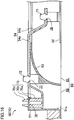
- extension
- plate member
- suspending support
- Prior art date
- Legal status (The legal status is an assumption and is not a legal conclusion. Google has not performed a legal analysis and makes no representation as to the accuracy of the status listed.)
- Granted
Links
Images









Classifications
-
- F—MECHANICAL ENGINEERING; LIGHTING; HEATING; WEAPONS; BLASTING
- F24—HEATING; RANGES; VENTILATING
- F24F—AIR-CONDITIONING; AIR-HUMIDIFICATION; VENTILATION; USE OF AIR CURRENTS FOR SCREENING
- F24F13/00—Details common to, or for air-conditioning, air-humidification, ventilation or use of air currents for screening
- F24F13/20—Casings or covers
-
- F—MECHANICAL ENGINEERING; LIGHTING; HEATING; WEAPONS; BLASTING
- F24—HEATING; RANGES; VENTILATING
- F24F—AIR-CONDITIONING; AIR-HUMIDIFICATION; VENTILATION; USE OF AIR CURRENTS FOR SCREENING
- F24F1/00—Room units for air-conditioning, e.g. separate or self-contained units or units receiving primary air from a central station
- F24F1/0007—Indoor units, e.g. fan coil units
- F24F1/0043—Indoor units, e.g. fan coil units characterised by mounting arrangements
- F24F1/0047—Indoor units, e.g. fan coil units characterised by mounting arrangements mounted in the ceiling or at the ceiling
-
- F—MECHANICAL ENGINEERING; LIGHTING; HEATING; WEAPONS; BLASTING
- F24—HEATING; RANGES; VENTILATING
- F24F—AIR-CONDITIONING; AIR-HUMIDIFICATION; VENTILATION; USE OF AIR CURRENTS FOR SCREENING
- F24F2221/00—Details or features not otherwise provided for
- F24F2221/26—Details or features not otherwise provided for improving the aesthetic appearance
Definitions
- the present disclosure relates to an indoor unit for an air conditioner, and more particularly, an indoor unit for an air conditioner provided in a ceiling.
- Patent Document 1 shows a ceiling-embedded air conditioner (i.e., an indoor unit) including a unit housing and a decorative panel.
- the lower portion of the unit housing is open to contain a blower and a heat exchanger.
- the decorative panel is provided under the unit housing.
- a front panel is fitted in an inlet formed at a central portion of the decorative panel.
- This front panel is liftably and lowerably suspended and supported by a lifting device, which is attached to the decorative panel, via wires.
- the lifting device winds up the wires to lift the front panel.
- the front panel is then placed in the inlet of the decorative panel to close the inlet.
- the lifting device lets out the wires to lower the front panel.
- a gap is then formed as an inlet opening between the front panel and the decorative panel.
- the front panel i.e., a grille
- the wires i.e., the wires.
- the front panel would be thus swayed by the air sucked from the gap (i.e., the inlet opening) between the decorative panel and the front panel. That is, the front panel is difficult to support stably.
- a first aspect of the present disclosure provides an indoor unit for an air conditioner provided in a ceiling (CE).
- the indoor unit includes an indoor unit body (20) including an indoor fan (31) and an indoor heat exchanger (32) inside, mounted in the ceiling (CE), controlling a temperature of air sucked from below, and blowing out the air; and a decorative panel (50) provided under the indoor unit body (20).
- the decorative panel (50) includes a panel body (51) vertically penetrated by an air inlet (51 a) at its central portion, and by air outlets (51b) around the air inlet (51a), a suspending support (54) including a first extension (54a) extending inward from an inner peripheral portion of the air inlet (51 a), and a second extension (54b) being integral with the first extension (54a), and extending downward from a tip portion of the first extension (54a), and a grille (52) being a plate connected to a lower end of the second extension (54b) of the suspending support (54), provided at a lower end portion of the air inlet (51 a), and covering a central portion of the air inlet (51 a) to form an inlet opening (60) between an outer peripheral edge of the grille (52) and an opening edge of the air inlet (51a) in plan view.
- a suspending support including a first extension (54a) extending inward from an inner peripheral portion of the air inlet (
- the grille (52) is supported by the suspending support (54).
- This configuration supports the grille (52) more strongly than the configuration in which the grille (52) is suspended by wires.
- the grille (52) covers the central portion of the air inlet (51 a) to form the inlet opening (60) between the outer peripheral edge of the grille (52) and the opening edge of the air inlet (51a) in plan view.
- This configuration secures the opening area of the inlet opening (60). In this manner, the opening area of the inlet opening (60) is secured, and the grille (52) is supported strongly.
- the first extension (54a) of the suspending support (54) is a plate standing vertically and extending inward from the inner peripheral portion of the air inlet (51a).
- the second extension (54b) of the suspending support (54) is a plate extending downward from the tip portion of the first extension (54a).
- the first extension (54a) of the suspending support (54) is a plate standing vertically. This configuration reduces an increase in the flow resistance caused by the arrangement of the suspending support (54).
- the second extension (54b) of the suspending support (54) is also a plate. This configuration increases the connecting area between the second extension (54b) of the suspending support (54) and the grille (52) as compared to the case where the second extension (54b) of the suspending support (54) is a bar. This increases the connecting strength between the suspending support (54) and the grille (52).
- the suspending support (54) is integral with at least one of the panel body (51) and the grille (52).
- the integration of the suspending support (54) with the panel body (51) increases the connecting strength between the suspending support (54) and the panel body (51).
- the integration of the suspending support (54) with the grille (52) increases the connecting strength between the suspending support (54) and the grille (52).
- the suspending support (54) is independent from the panel body (51) and the grille (52).
- the suspending support (54) is independent from the panel body (51) and the grille (52).
- the panel body (51), the grille (52), and the suspending support (54) can be manufactured independently.
- the suspending support (54) is connected to at least one of the panel body (51) and the grille (52) by claw fitting.
- the suspending support (54) is connected to the panel body (51) by claw fitting.
- the claw fitting facilitates the connection between the suspending support (54) and the panel body (51).
- the suspending support (54) is also connected to the grille (52) by claw fitting.
- the claw fitting facilitates the connection between the suspending support (54) and the grille (52).
- the suspending support (54) is connected to at least one of the panel body (51) and the grille (52) by screwing.
- the suspending support (54) is connected to the panel body (51) by screwing. This configuration facilitates the attachment and detachment of the suspending support (54) to and from the panel body (51).
- the suspending support (54) is also connected to the grille (52) by screwing. This configuration facilitates the attachment and detachment of the suspending support (54) to and from the grille (52).
- the air inlet (51 a) has a rectangular shape in plan view.
- the grille (52) has a rectangular shape in plan view.
- the first extension (54a) of the suspending support (54) extends from a side portion of the air inlet (51 a) to a side portion of the grille (52) in plan view.
- the lower end of the second extension (54b) of the suspending support (54) is connected to the side portion of the grille (52).
- the air passing through the region of the inlet opening (60) between a corner of the air inlet (51a) and a corner of the grille (52) tends to flow at a higher velocity than the air passing through the region of the inlet opening (60) between the side portion of the air inlet (51 a) and the side portion of the grille (52).
- the arrangement of the suspending support (54) at the side portion of the grille (52) effectively reduces an increase in the flow resistance caused by the arrangement of the suspending support (54).
- the air inlet (51 a) has a rectangular shape in plan view.
- the grille (52) has a rectangular shape in plan view.
- the first extension (54a) of the suspending support (54) extends from a corner of the air inlet (51a) to a corner of the grille (52) in plan view.
- the lower end of the second extension (54b) of the suspending support (54) is connected to the corner of the grille (52).
- the suspending support (54) is disposed at the corner of the grille (52). This configuration supports the grille (52) more strongly than the configuration in which the suspending support (54) is disposed at the side portion of the grille (52).
- the decorative panel (50) further includes a plate member (53) inside the air inlet (51 a).
- the plate member (53) extends along the inner surface of the air inlet (51 a).
- the plate member (53) is disposed inside the air inlet (51a) such that an upper edge of the plate member (53) is located more inward than a lower edge of the plate member (53).
- the upper edge of the plate member (53) is located above a lower end of the air inlet (51a).
- the lower edge of the plate member (53) surrounds an outer periphery of the grille (52) in plan view.
- the plate member (53) is provided. This configuration secures the opening area of the inlet opening (60), and makes the inner parts of the indoor unit (10) less visible through the inlet opening (60).
- a lower portion of the first extension (54a) of the suspending support (54) has a shape corresponding to an outer peripheral surface of the plate member (53).
- the lower portion of the first extension (54a) is connected to the outer peripheral surface of the plate member (53).
- the lower portion of the first extension (54a) of the suspending support (54) has the shape corresponding to the shape of the outer peripheral surface of the plate member (53) to be connected to the outer peripheral surface of the plate member (53).
- This configuration increases the connecting area between the suspending support (54) and the plate member (53). This increases the connecting strength between the suspending support (54) and the plate member (53).
- the first aspect of the present disclosure secures the opening area of the inlet opening (60), and supports the grille (52) strongly. This reduces an increase in the flow resistance at the inlet opening (60), and stabilizes the support of the grille (52).
- the second aspect of the present disclosure reduces an increase in the flow resistance caused by the arrangement of the suspending support (54), and thus smoothens the air flowing through the air inlet (51 a).
- the second aspect increases the connecting strength between the suspending support (54) and the grille (52), thereby supporting the grille (52) more stably.
- the third aspect of the present disclosure increases at least one of the connecting strength between the suspending support (54) and the panel body (51), and the connecting strength between the suspending support (54) and the grille (52). This leads to more stable support of the grille (52).
- the fourth aspect of the present disclosure enables independent manufacturing of the panel body (51), the grille (52), and the suspending support (54). This facilitates the manufacturing of the decorative panel (50).
- the fifth aspect of the present disclosure facilitates at least one of the connection between the suspending support (54) and the panel body (51), and the connection between the suspending support (54) and the grille (52). This facilitates the assembly of the decorative panel (50).
- the sixth aspect of the present disclosure facilitates at least one of the attachment and detachment of the suspending support (54) to and from the panel body (51), and the attachment and detachment of the suspending support (54) to and from the grille (52). This facilitates the assembly and disassembly of the decorative panel (50).
- the seventh aspect of the present disclosure effectively reduces an increase in the flow resistance caused by the arrangement of the suspending support (54). This leads to smooth air flow through the air inlet (51a).
- the eighth aspect of the present disclosure supports the grille (52) strongly. This leads to more stable support of the grille (52).
- the ninth aspect of the present disclosure secures the opening area of the inlet opening (60), and makes the inner parts of the indoor unit (10) less visible through the inlet opening (60). This reduces an increase in the flow resistance at the inlet opening (60), and improves the design of the decorative panel (50).
- the tenth aspect of the present disclosure increases the connecting strength between the suspending support (54) and the plate member (53). This allows the suspending support (54) to support the plate member (53) more strongly.
- FIG. 1 illustrates an exemplary configuration of an indoor unit (10) of an air conditioner according to an embodiment 1.
- the indoor unit (10) is provided in a ceiling (CE) inside a room whose air is to be conditioned.
- the indoor unit (10) is connected to an outdoor unit (not shown) by pipes to form an air conditioner.
- This air conditioner performs air conditioning such as cooling or heating.
- the indoor unit (10) includes an indoor unit body (20), a chamber (40), and a decorative panel (50).
- the indoor unit (10) is suspended by a suspender mechanism (not shown) located in a space above a ceiling (CE) (i.e., in a ceiling plenum).
- FIG. 1 is a perspective view of the indoor unit (10) as seen obliquely from below.
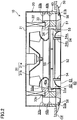
- FIG. 2 is a longitudinal sectional view of the indoor unit (10) taken along the line II-II of FIG. 3.
- FIG. 3 is a bottom view of the decorative panel (50) as seen from below.
- FIG. 4 is a top view of the decorative panel (50) as seen from above.
- the indoor unit body (20) includes an indoor fan (31) and an indoor heat exchanger (32) inside and is provided in the ceiling (CE).
- the indoor unit body (20) controls a temperature of air sucked from below, and blows out the air.
- the indoor unit body (20) includes a casing (21), a drain pan (33), and a bell mouth (34) in addition to the indoor fan (31) and the indoor heat exchanger (32).
- the casing (21) is like a rectangular parallelepiped box with an openable lower surface.
- a heat insulating material (not shown) is provided on the inner surface of the casing (21).
- the casing (21) houses the indoor fan (31), the indoor heat exchanger (32), the drain pan (33), and the bell mouth (34).
- the indoor fan (31) is disposed at the center in the casing (21).
- the indoor fan (31) blows air, which has been sucked from below, radially outward from sides.
- the indoor fan (31) includes a fan motor (31 a) and a vaned wheel (31b).
- the fan motor (31a) is fixed to the top plate of the casing (21).
- the vaned wheel (31 b) is connected to the rotation shaft of the fan motor (31a).
- the indoor heat exchanger (32) surrounds the indoor fan (31), and performs heat exchange between refrigerant and air transported by the indoor fan (31).
- the indoor heat exchanger (32) is a fin and tube heat exchanger of a cross-fin type.
- the indoor heat exchanger (32) is connected to a compressor, an outdoor heat exchanger, and an expansion valve by pipes to form a refrigerant circuit.
- the indoor heat exchanger (32) is provided in the indoor unit (10).
- the compressor, the outdoor heat exchanger, and the expansion valve are provided in an outdoor unit (not shown).
- the refrigerant circulates in forward and reverse directions to allow this refrigerant circuit to perform vapor compression refrigeration cycles.
- the indoor heat exchanger (32) functions as an evaporator in cooling operations to cool air, and functions as a radiator (condenser) in heating operations to heat air.
- the drain pan (33) has a rectangular parallelepiped shape with a low height, and is disposed under the indoor heat exchanger (32).
- a single air inlet (33a), a plurality of (four in this example) air outlets (33b), and a drain groove (33c) are formed in the drain pan (33).
- the air inlet (33a) is formed at the central portion of the drain pan (33), and vertically penetrates the drain pan (33).
- the four air outlets (33b) surround the air inlet (33a) and vertically penetrate the drain pan (33).
- the drain groove (33c) has a ring shape extending along the lower end of the indoor heat exchanger (32), and receives water condensed in the indoor heat exchanger (32).
- each of the four air outlets (33b) extends along one of four sides of the drain pan (33) in plan view.
- the drain groove (33c) extends in a ring shape between the air inlet (33a) and the four air outlets (33b) in plan view.
- the bell mouth (34) has a cylindrical shape with an opening area increasing from its upper edge to its lower edge. With the upper edge of the bell mouth (34) inserted into the lower open end (i.e., the inlet) of the indoor fan (31), the bell mouth (34) is contained in the air inlet (33a) of the drain pan (33).
- the chamber (40) has a rectangular parallelepiped shape with a low height, and is disposed under the indoor unit body (20).
- a single inlet opening (40a) for communication, and a plurality of (four in this example) outlet openings (40b) for communication are formed in the chamber (40).
- the inlet opening (40a) is formed at the central portion of the chamber (40), and vertically penetrates the chamber (40) to communicate with the air inlet (33a) of the drain pan (33).
- the four outlet openings (40b) surround the inlet opening (40a).
- Each of the four outlet openings (40b) vertically penetrates the chamber (40) to communicate with one of the four air outlets (33b) of the drain pan (33).
- each of the four outlet openings (40b) extends along one of four sides of the chamber (40) in plan view.
- the decorative panel (50) is provided below the indoor unit body (20) with the chamber (40) interposed therebetween.
- the decorative panel (50) includes a panel body (51), a grille (52), a plate member (53), a plurality of (four in this example) suspending supports (54), a filter (55), and a plurality of (four in this example) air flow direction control vanes (56).
- the panel body (51) has a rectangular parallelepiped shape with a low height.
- a single air inlet (51a) and a plurality of (four in this example) air outlets (51b) are formed in the panel body (51).
- the panel body (51) has a square shape in plan view.
- the central portion (specifically, the portion more inward than the four air outlets (51b)) of the lower surface of the panel body (51) is flat, and the outer peripheral edge portion of the lower surface is inclined gently upward toward the outer periphery.
- the air inlet (51a) is formed at the central portion of the panel body (51), and vertically penetrates the panel body (51) to communicate with the inlet opening (40a) of the chamber (40). Specifically, the air inlet (51a) communicates with the air inlet (33a) of the drain pan (33) via the inlet opening (40a) of the chamber (40).
- the air inlet (51a) has a square shape in plan view. The opening area of the air inlet (51a) is uniform from its upper end to its lower end.
- the four air outlets (51b) surround the air inlet (51a).
- Each air outlet (51b) vertically penetrates the panel body (51) to communicate with one of the four outlet openings (40b) of the chamber (40).
- the four air outlets (51b) communicate with the four air outlets (33b) of the drain pan (33) via the four outlet openings (40b) of the chamber (40).
- each of the four air outlets (51b) extends along one of four sides of the panel body (51).
- the words “inward” and “inner side” are used to represent the side closer to the center of the air inlet (51a) in plan view, and the words “outward” and “outer side” are used to represent the side farther from the center of the air inlet (51 a) in plan view.
- the grille (52) is a plate (specifically, a non-porous plate) blocking air flow, and provided at the lower end portion of the air inlet (51a).
- the grille (52) covers the central portion of the air inlet (51 a) to form an inlet opening (60) between the outer peripheral edge of the grille (52) and the opening edge of the air inlet (51a) in plan view.
- the grille (52) is a square plate smaller than the air inlet (51a), which has a square shape in plan view.
- the grille (52) is provided at the lower end portion of the air inlet (51a) such that the lower surface of the grille (52) is at the same height as the lower end of the air inlet (51a).
- the lower surface of the grille (52) is flat, and is flush with the central portion of the lower surface of the panel body (51) with the inlet opening (60) interposed therebetween.
- the state that "the lower surface of the grille (52) is at the same height as the lower end of the air inlet (51a)” includes not only the state that the lower surface of the grille (52) is at exactly the same height as the lower end of the air inlet (51a) (e.g., there is no difference in height between the lower surface of the grille (52) and the lower end of the air inlet (51a)) but also the state that the lower surface of the grille (52) is at substantially the same height as the lower end of the air inlet (51a) (e.g., there is a difference in height within about 5 mm between the lower surface of the grille (52) and the lower end of the air inlet (51a)).
- the plate member (53) extends along the inner surface of the air inlet (51 a).
- the plate member (53) is provided inside the air inlet (51a) such that the upper edge of the plate member (53) is located more inward than the upper edge of the plate member (53).
- the upper edge of the plate member (53) is located above the lower end of the air inlet (51a).
- the lower edge of the plate member (53) surrounds the outer periphery of the grille (52) in plan view.
- the plate member (53) extends continuously along the entire inner surface of the air inlet (51 a).
- the plate member (53) curves to be recessed from the outer peripheral edge of the grille (52).
- the plate member (53) has a frame shape with a square transverse section.
- the plate member (53) curves like an arc to be recessed from the outer peripheral edge of the grille (52) such that the upper edge of the plate member (53) is more inward than the lower edge of the plate member (53).
- the lower edge of the plate member (53) is located between the inner and outer peripheral edges of the inlet opening (60) in plan view to divide the inlet opening (60) into a first inlet opening (61) and a second inlet opening (62) in plan view.
- the first inlet opening (61) is located more inward than the lower edge of the plate member (53).
- the second inlet opening (62) is located more outward than the lower edge of the plate member (53).
- the inner peripheral edge of the inlet opening (60) corresponds to the outer peripheral edge of the grille (52).
- the outer peripheral edge of the inlet opening (60) corresponds to the opening edge of the air inlet (51 a).
- each suspending support (54) includes a first extension (54a) and a second extension (54b).
- FIG. 5 is an enlarged partial perspective view of the suspending supports (54) as seen obliquely from above.
- FIG. 6 is an enlarged partial longitudinal sectional view illustrating the proximity of the suspending supports (54) out of the longitudinal section of the decorative panel (50) taken along the direction in which the first extension (54a) of one of the suspending supports (54) extends.
- FIG. 6 is a partial longitudinal sectional view taken along the line VI-VI of FIG. 4 .
- the first extension (54a) of each suspending support (54) extends inward from an inner peripheral portion of the air inlet (51 a).
- the second extension (54b) is integral with the first extension (54a), and extends downward from the tip portion of the first extension (54a).
- the "inner peripheral portion of the air inlet (53)" is a portion of the panel body (51) forming the air inlet (51a) (i.e., surrounding the air inlet (51a)).
- the inner peripheral portion of the air inlet (51a) includes not only the portion of the panel body (51) corresponding to the inner peripheral surface of the air inlet (51a), but also the portion of the panel body (51) continuous with the inner peripheral surface of the air inlet (51a) (e.g., the inner peripheral edge of the upper end surface continuous with the upper end of the inner peripheral surface of the air inlet (51a)).
- the first extension (54a) i.e., the extension
- the second extension (54b) the suspender
- the first extension (54a) is a plate extending inward from the inner peripheral portion of the air inlet (51a).
- the second extension (54b) is a plate extending downward from the tip portion of the first extension (54a).
- the first extension (54a) of each suspending support (54) includes a pair of plates standing vertically at a distance and extending inward from the inner peripheral surface of the air inlet (51a).
- the second extension (54b) of each suspending support (54) is a plate extending vertically. The short directional ends of the second extension (54b) are connected to the tip portions of the two plates of the first extension (54a) of the suspending support (54).
- the grille (52) is connected to the lower end of the second extension (54b) of the four suspending supports (54), and disposed at the lower end portion of the air inlet (51a).
- each of the four suspending supports (54) is arranged at one of four corners of the grille (52).
- the air inlet (51a) has a rectangular shape in plan view.
- the grille (52) has a rectangular shape in plan view.
- the first extension (54a) of each suspending support (54) extends from one of the corners of the air inlet (51 a) to the associated one of the corners of the grille (52) in plan view.
- a lower end of the second extension (54b) of the suspending support (54) is connected to the associated one of the corners of the grille (52).
- each suspending support (54) curves along the outer edge of the associated one of the corners in plan view. That is, the second extension (54b) of each suspending support (54) is an arc-like plate (i.e., a plate with an arc-like cross-section). While, in this example, the second extension (54b) of each suspending support (54) is connected to the outer edge of the associated one of the corners of the grille (52), it may be connected to the portion of the corner of the grille (52) inner than the outer edge.
- the plate member (53) is connected to the lower portion of the first extension (54a) of each of the four suspending supports (54), and disposed inside the air inlet (51 a).
- the lower portion of the first extension (54a) of each of the four suspending supports (54) is connected to one of four corners of the plate member (53), which is like a frame with a square transverse section.
- the lower portion of the first extension (54a) of each suspending support (54) has a shape corresponding to the shape of the outer peripheral surface of the plate member (53).
- the outer peripheral surface of the plate member (53) is connected to the lower portion of the first extension (54a).
- the lower portion of the first extension (54a) of each suspending support (54) has an arc shape to be recessed from the outer peripheral edge of the grille (52).
- the outer peripheral surface of the plate member (53) is fitted in and connected to the lower portion of the first extension (54a).
- a part of the panel body (51) (specifically, the portion near the air inlet (51a)), the grille (52), the plate member (53), and the four suspending supports (54) are formed integrally.
- the filter (55) is provided above the air inlet (51 a) of the panel body (51), and catches dust in the air, which has passed through the air inlet (51a).
- the filter (55) is a square lattice in plan view, and attached above the central portion of the panel body (51) to cover the air inlet (51 a).
- the area of the filter (55) is equal to the opening area of the upper end of the air inlet (51a) in plan view.
- the area of the filter (55) may be larger than the opening area of the upper end of the air inlet (51a) in plan view.
- each of the air flow direction control vanes (56) is provided at the lower end portion of each of the four air outlets (51b) of the panel body (51) to control the direction of the air flowing through the air outlets (51b).
- Each air flow direction control vane (56) is a plate extending along the length of the associated one of the air outlets (51b), and provided with a rocking shaft at each of two longitudinal ends.
- Each air flow direction control vane (56) is supported by the panel body (51) to be rockable about the rocking shaft.
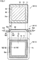
- FIG. 7 illustrates a longitudinal section of the decorative panel (50).
- the top of FIG. 7 illustrates the main part of the decorative panel (50) (near the air inlet (51a)) as seen from above.
- the bottom of FIG. 7 illustrates the main part of the decorative panel (50) as seen from below.
- the center of FIG. 7 does not show the suspending supports (54), the filter (55), or the air flow direction control vanes (56).
- the first inlet opening (61) has a larger opening area than the second inlet opening (62).
- the first inlet opening (61) is indicated by narrow hatching from bottom left to top right
- the second inlet opening (62) is indicated by narrow hatching from top left to bottom right.
- the first opening (63) has a larger opening area than the second opening (64).
- the first opening (63) is the region surrounded by the upper edge of the plate member (53).
- the second opening (64) is, in plan view, interposed between the upper edge of the plate member (53) and the inner peripheral surface of the air inlet (51 a).
- the first opening (63) is indicated by wide hatching from bottom left to top right
- the second opening (64) is indicated by wide hatching from top left to bottom right.
- the ratio of the opening area of the first inlet opening (61) to the second inlet opening (62) is higher than the ratio of the opening area of the first opening (63) to the second opening (64).
- the ratio of the opening area of the first inlet opening (61) to the second inlet opening (62) may be equal to the ratio of the opening area of the first opening (63) to the second opening (64).
- the lower edge of the plate member (53) is at the same height as the lower end of the air inlet (51a).
- the lower edge of the plate member (53) may be higher than the lower end of the air inlet (51 a).
- the lower edge of the plate member (53) is, in plan view, located more outward than the center line (CL) between the inner and outer peripheral edges of the inlet opening (60).
- the lower edge of the plate member (53) is at the same height as the lower surface of the grille (52).
- the lower edge of the plate member (53) may be higher than the lower surface of the grille (52).
- the state that "the lower edge of the plate member (53) is at the same height as the lower end of the air inlet (51 a) (or the lower surface of the grille (52)) includes not only the state that the lower edge of the plate member (53) is at exactly the same height as the lower end of the air inlet (51 a) (or the lower surface of the grille (52)) (e.g., there is no difference in height), but also the state that the lower edge of the plate member (53) is at substantially the same height as the lower end of the air inlet (51 a) (or the lower surface of the grille (52)) (e.g., there is a difference in height within 5 mm).
- the upper edge of the plate member (53) overlaps the outer peripheral edge of the grille (52) in plan view.
- the upper edge of the plate member (53) may be located more inward than the outer peripheral edge of the grille (52), in plan view.
- the plate member (53) is disposed inside the air inlet (51 a) such that the upper edge of the plate member (53) is located more inward than the lower edge of the plate member (53).
- inner parts of the indoor unit (10) i.e., the filter (55) in this example
- the upper edge of the plate member (53) overlaps the outer peripheral edge of the grille (52), and the lower edge of the plate member (53) is, in plan view, interposed between the inner and outer peripheral edges of the inlet opening (60).
- the filter (55) is partially visible in the region (i.e., the second inlet opening (62)) of the inlet opening (60) located more outward than the lower edge of the plate member (53) in plan view, but the rest of the filter (55) is hidden by the plate member (53) in the region (i.e., the first inlet opening (61)) of the inlet opening (60) located more inward than the lower edge of the plate member (53) in plan view.
- FIG. 8 does not show the suspending supports (54).
- the indoor fan (31) When the indoor fan (31) operates, indoor air is sucked from the inlet opening (60) to the air inlet (51a). At the air inlet (51a), the indoor air, which has been sucked from the inlet opening (60), is branched at the lower edge of the plate member (53) into the inner and outer sides of the plate member (53). The indoor air is divided into the air flowing through an inner side of the plate member (53) and the air flowing through an outer side of the plate member (53). Specifically, a first ventilation path (R1) and a second ventilation path (R2) are provided inside the air inlet (51a).
- the air flows from the inlet opening (60) toward the upper end of the air inlet (51 a) through the inner side of the plate member (53).
- the air flows from the inlet opening (60) toward the upper end of the air inlet (51a) through the outer side of the plate member (53).
- the air which has flowed to the inner side of the plate member (53), is guided along the inner peripheral surface of the plate member (53) toward the center of the air inlet (51 a), and flows toward the upper end of the air inlet (51 a).
- the air which has passed through the first ventilation path (R1), passes through the central portion of the filter (55) and then through the bell mouth (34) to be sucked into the indoor fan (31).
- the air, which has flowed to the outer side of the plate member (53) passes between the outer peripheral surface of the plate member (53) and the inner peripheral surface of the air inlet (51a) toward the upper end of the air inlet (51a) without changing the flow direction largely with the plate member (53).
- the air, which has passed through the second ventilation path (R2) passes through the peripheral edge portion (the portion around the central portion) of the filter (55) and then through the bell mouth (34) to be sucked into the indoor fan (31).
- the air sucked into the indoor fan (31) is blown radially outward from the sides of the indoor fan (31).
- the air blown out of the indoor fan (31) exchanges heat with refrigerant flowing through the indoor heat exchanger (32), when passing through the indoor heat exchanger (32).
- the air, which has passed through the indoor heat exchanger (32) is branched into the four air outlets (33b) and flow downward through the four air outlets (33b).
- the air, which has passed through the four air outlets (33b) sequentially passes through the four inlet openings (40a) and the four air outlets (51b) and is blown into the room.
- the suspending support (54) is used to support the grille (52).
- This configuration supports the grille (52) more strongly than the configuration suspending the grille (52) by wires.
- the grille (52) covers the central portion of the air inlet (51a) to form the inlet opening (60) between the outer peripheral edge of the grille (52) and the opening edge of the air inlet (51 a) in plan view.
- This configuration secures the opening area of the inlet opening (60). In this manner, securing of the opening area of the inlet opening (60) and the strong support of the grille (52) reduce an increase in the flow resistance at the inlet opening (60), and stabilize the support of the grille (52).
- each suspending support (54) is a plate standing vertically. This configuration reduces an increase in the flow resistance caused by the arrangement of the suspending supports (54). This smoothens the air flowing through the air inlet (51a).
- the first extension (54a) of each suspending support (54) includes the pair of plates. This configuration increases the connecting strength between the first extension (54a) of the suspending support (54) and the panel body (51), and the connecting strength between the first extension (54a) and the second extension (54b) of the suspending support (54) as compared to the case where the first extension (54a) is a single plate.
- the second extension (54b) of the suspending support (54) is the plate.
- This configuration increases the connecting area between the second extension (54b) of the suspending support (54) and the grille (52) as compared to the case where the second extension (54b) of the suspending support (54) is a bar. This increases the connecting strength between the suspending support (54) and the grille (52).
- the suspending support (54) is integral with the panel body (51) and the grille (52). This configuration increases the connecting strength between the suspending support (54) and the panel body (51), and the connecting strength between the suspending support (54) and the grille (52). This leads to more stable support of the grille (52).
- suspending support (54) is integral with the panel body (51), it may be independent from the grille (52). While the suspending support (54) is integral with the grille (52), it may be independent from the panel body (51).
- the integration of the suspending support (54) with the panel body (51) increases the connecting strength between the suspending support (54) and the panel body (51).
- the integration of the suspending support (54) with the grille (52) increases the connecting strength between the suspending support (54) and the grille (52). That is, the integration of the suspending support (54) with at least one of the panel body (51) and the grille (52) increases at least one of the connecting strength between the suspending support (54) and the panel body (51), and the connecting strength between the suspending support (54) and the grille (52). This leads to more stable support of the grille (52).
- Each suspending support (54) is disposed at the associated one of the corners of the grille (52). This configuration supports the grille (52) more strongly than the configuration disposing each suspending support (54) on the associated one of the sides of the grille (52). This leads to more stable support of the grille (52).
- the plate member (53) is provided as follows.
- the upper edge of the plate member (53) is located more inward than the lower edge of the plate member (53).
- the upper edge of the plate member (53) is located above the lower end of the air inlet (51 a).
- the lower edge of the plate member (53) surrounds the outer periphery of the grille (52) in plan view.
- This configuration secures the opening area of the inlet opening (60), and makes the inner parts of the indoor unit (10) (i.e., the filter (55) in this example) less visible through the inlet opening (60). This reduces an increase in the flow resistance at the inlet opening (60), and improves the design of the decorative panel (50).
- each suspending support (54) has a shape corresponding to the outer peripheral surface of the plate member (53) to be connected to the outer peripheral surface of the plate member (53). This configuration increases the connecting area between the suspending supports (54) and the plate member (53). This increases the connecting strength between the suspending supports (54) and the plate member (53), thereby reinforcing the support of the plate member (53) using the suspending supports (54).
- the plate member (53) is provided such that the upper edge of the plate member (53) is located more inward than the lower edge of the plate member (53). This configuration guides the air flowed to the inner side of the plate member (53) toward the center of the air inlet (51 a). This accelerates the air flowing through the central portion (i.e., the central portion in plan view) of the air inlet (51 a).
- the inlet of the indoor fan (31) is often disposed at the central portion of the indoor unit body (20) (at the central portion of the air inlet (33a) of the drain pan (33) in this example) in plan view.
- the acceleration of the air flowing through the central portion of the air inlet (51a) accelerates the air sucked into the indoor fan (31) in the indoor unit body (20).
- the efficiency in sucking the air in the indoor unit body (20) improves.
- the plate member (53) curves to be recessed from the outer peripheral edge of the grille (52). This secures a longer distance between the plate member (53) and the grille (52) than in the case where the plate member (53) curves to be raised toward the outer peripheral edge of the grille (52). This reduces the flow resistance on the inner side of the plate member (53), and smoothens the air flowing through the inner side of the plate member (53). As a result, the air flowing through the central portion of the air inlet (51 a) is accelerated.
- the plate member (53) is provided such that the lower edge of the plate member (53) divides the inlet opening (60) into the first inlet opening (61) and the second inlet opening (62) in plan view.
- the second ventilation path (R2) passing through the outer side of the plate member (53) is provided inside the air inlet (51a).
- the air which has flowed to the outer side of the plate member (53), flows toward the upper end of the air inlet (51a) without changing the flow direction largely with the plate member (53). That is, the second ventilation path (R2) has a lower flow resistance than the first ventilation path (R1).
- the provision of the second ventilation path (R2) in addition to the first ventilation path (R1) inside the air inlet (51a) reduces more flow resistance at the air inlet (51 a) than in the case where the air sucked from the inlet opening (60) passes only through the inner side of the plate member (53) (i.e., only the first ventilation path (R1) is provided), and thus smoothens the air flowing through the air inlet (51 a).
- the plate member (53) is provided such that the lower edge of the plate member (53) divides the inlet opening (60) into the first inlet opening (61) and the second inlet opening (62) in plan view. Then, the first and second ventilation paths (R1) and (R2) are provided inside the air inlet (51a). The air, which has passed through the first ventilation path (R1), is fed to the central portion of the filter (55). The air, which has passed through the second ventilation path (R2), is fed to a peripheral edge portion of the filter (55) (for example, the portion hidden by the plate member (53) when the indoor unit (10) is seen from below). Therefore, not only the central portion of the filter (55) but also the peripheral edge portion of the filter (55) can be utilized efficiently.
- the first inlet opening (61) has a larger opening area than the second inlet opening (62) so that the flow resistance at the entrance of the first ventilation path (R1) is lower than the flow resistance at the entrance of the second ventilation path (R2). This accelerates the air flowing into the first ventilation path (R1), and thus accelerates the air flowing through the central portion of the air inlet (51a).
- the first opening (63) has a larger opening area than the second opening (64) so that the flow resistance at the exit of the first ventilation path (R1) is lower than the flow resistance at the exit of the second ventilation path (R2). This accelerates the air flowing out of the first ventilation path (R1), and thus accelerates the air flowing through the central portion of the air inlet (51 a).
- the ratio of the opening area of the first inlet opening (61) to the second inlet opening (62) is higher than or equal to the ratio of the opening area of the first opening (63) to the second opening (64).
- This configuration smoothens more air flowing through the first ventilation path (R1) than the other configuration (i.e., in which the ratio of the opening area of the first inlet opening (61) to the second inlet opening (62) is lower than the ratio of the opening area of the first opening (63) to the second opening (64)). This accelerates the air flowing through the central portion of the air inlet (51a).
- the lower edge of the plate member (53) is at the same height as or higher than the lower end of the air inlet (51a). This configuration makes the plate member (53) less conspicuous than the configuration in which the lower edge of the plate member (53) projects downward beyond the air inlet (51a). This improves the design of the decorative panel (50).
- the plate member (53) is provided such that the lower edge of the plate member (53) is located more outward than the center line (CL) between the inner and outer peripheral edges of the inlet opening (60) in plan view.
- This configuration reduces a gap between the outer peripheral edge of the inlet opening (60) and the lower edge of the plate member (53) than the configuration in which the lower edge of the plate member (53) is located more inward than the center line (CL) in plan view. This makes the inner parts of the indoor unit (10) less visible through the inlet opening (60), and thus improves the design of the decorative panel (50).
- the plate member (53) is provided such that the upper edge of the plate member (53) overlaps the outer peripheral edge of the grille (52) or is located more inward than the outer peripheral edge of the grille (52) in plan view. This configuration makes the inner parts of the indoor unit (10) less visible in the region of the inlet opening (60) more inward than the lower edge of the plate member (53), when the indoor unit (10) is seen in plan view from the bottom. This improves the design of the decorative panel (50).
- the grille (52) is provided such that the lower surface of the grille (52) is at the same height as the lower end of the air inlet (51 a). This configuration improves integration (feeling of flatness) between the panel body (51) and the grille (52) more than the configuration in which the grille (52) projects below the panel body (51). This improves the design of the decorative panel (50).
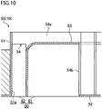
- the plate member (53) may be configured such that the curvature radius (CR) of the plate member (53) having the curvature center at the outer peripheral edge of the grille (52) gradually increases from the lower edge toward the upper edge of the plate member (53).
- a chain double-dashed line represents the inner peripheral surface of the plate member (53) where the plate member (53) has a uniform curvature radius from the upper edge toward the lower edge of the plate member (53).
- the distance between the plate member (53) and the grille (52) gradually increases from the lower edge toward the upper edge of the plate member (53). This gradually reduces the flow resistance on the inner side of the plate member (53) from the lower edge toward the upper edge of the plate member (53), and smoothens the air flowing through the inner side of the plate member (53) (i.e., the air flowing through the first ventilation path (R1)). This accelerates the air flowing through the central portion of the air inlet (51a).
- the plate member (53) may curve (or bend) in an L-shape to be recessed from the outer peripheral edge of the grille (52). As shown in FIG. 11 , the plate member (53) may be inclined upward in a line from the outer periphery toward the inside of the air inlet (51a).
- This configuration also guides the air flowed to the inner side of the plate member (53) toward the center of the air inlet (51a), thereby accelerating the air flowing through the central portion of the air inlet (51 a).
- the grille (52) may be provided at the lower end portion of the air inlet (51a) such that the lower surface of the grille (52) is higher than the lower end of the air inlet (51 a).
- the grille (52) has a flat lower surface, which is parallel to the lower surface of the panel body (51).
- This configuration also improves the integration between the panel body (51) and the grille (52) as compared to the case where the grille (52) projects below the panel body (51).
- each of the four suspending supports (54) may be arranged at one of four side portions of the grille (52) (e.g., at the center of the side portion in this example).
- the air inlet (51a) has a rectangular shape in plan view
- the grille (52) has a rectangular shape in plan view.
- the first extension (54a) of each suspending support (54) extends from a side portion of the air inlet (51 a) to a side portion of the grille (52) in plan view.
- a lower end of the second extension (54b) of the suspending support (54) is connected to the associated one of the side portions of the grille (52).
- the second extension (54b) of the suspending support (54) may be connected to the outer edge of the associated one of the side portions of the grille (52), or a portion of the side portion of the grille (52) inner than the outer edge.
- the lower portion of the first extension (54a) of each suspending support (54) is connected to one of four side portions of the plate member (53), which is like a frame shape with a square transverse section.
- the “side portion of the air inlet (51a)” is a part of the inner peripheral portion of the air inlet (51a), which has a rectangular shape in plan view.
- the “side portion of the air inlet (51a)” is the portion on each side of the air inlet (51a) and excludes the part of the inner peripheral portion around any of four corners of the air inlet (51a).
- the “side portion of the grille (52)” is a part of the outer peripheral portion of the grille (52), which has a rectangular shape in plan view.
- the “side portion of the grille (52)” is the portion on each side of the grille (52), and excludes the part of the outer peripheral portion around any of four corners of the grille (52).
- the “side portion of the plate member (53)” is a part of the plate member (53) like a rectangular frame in plan view.
- the “side portion of the plate member (53)” is the portion on each side of the plate member (53) and excludes the part around any of four corners of the plate member (53).
- the air passing through the region of the inlet opening (60) between each corner of the air inlet (51 a) and the corresponding corner of the grille (52) flows at a higher velocity than the air passing through the region of the inlet opening (60) between each side portion of the air inlet (51a) and the corresponding side portion of the grille (52).
- the arrangement of each suspending support (54) on the associated one of the sides of the grille (52) effectively reduces an increase in the flow resistance caused by the arrangement of the suspending support (54). This smoothens the air flowing through the air inlet (51 a).
- each suspending support (54) may be a single plate.
- the first extension (54a) of each suspending support (54) is a single plate extending inward from the inner peripheral surface of the air inlet (51a), while standing vertically.
- the second extension (54b) of each suspending support (54) is a plate extending vertically. One lateral end of the second extension (54b) is connected to the tip portion of the first extension (54a) of the suspending support (54).
- the first extension (54a) of each suspending support (54) is a single plate standing vertically. This configuration reduces an increase in the flow resistance caused by the arrangement of the suspending support (54). This smoothens the air flowing through the air inlet (51a).
- the second extension (54b) of each suspending support (54) is also a plate. This configuration increases the connecting area between the second extension (54b) of the suspending support (54) and the grille (52) as compared to the case where the second extension (54b) of the suspending support (54) is a bar. This increases the connecting strength between the suspending support (54) and the grille (52), and thus supports the grille (52) more stably.
- the suspending support (54) may be independent from the panel body (51) and the grille (52).
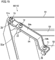
- the suspending support (54) is connected to the panel body (51) and the grille (52) by claw fitting.
- the first extension (54a) of each suspending support (54) is a plate extending inward from the inner peripheral surface of the air inlet (51a).
- a downward recess is formed at the base of the first extension (54a).
- the second extension (54b) of each suspending support (54) is a plate inclined downward from the tip portion of the first extension (54a) of the suspending support (54) toward the inside of the air inlet (51 a).
- the tip portion of the second extension (54b) bends in an L-shape in parallel with the upper surface of the grille (52).
- the panel body (51) is provided with an extending piece (51c), which extends inward from the inner peripheral surface of the air inlet (51a).
- the grille (52), the plate member (53), and the suspending support (54) are provided with a first engaging claw (71), a second engaging claw (72), and a third engaging claw (73), respectively, which project upward.
- the first engaging claw (71) is provided at a corner of the grille (52).
- the second engaging claw (72) is provided at a corner of the plate member (53).
- the third engaging claw (73) is provided in a recess, which is formed at the base of the first extension (54a) of the suspending support (54).
- the third engaging claw (73) includes a body (70a), a neck (70b), and a head (70c).
- the body (70a) has a pillar shape projecting upward.
- the neck (70b) has a cylindrical shape with a diameter smaller than that of the body (70a).
- the head (70c) has a truncated cone-shape.
- the head (70c) has a larger diameter than the neck (70b), which gradually decreases from the base to the tip portion.
- a slit is formed in the third engaging claw (73), in the direction in which the third engaging claw (73) projects.
- the diameter of the third engaging claw (73) may be reduced by elastic deformation.
- the first and second engaging claws (71) and (72) have a configuration similar to this configuration of the third engaging claw (73).
- First and second engaging holes (76) and (77) vertically penetrate the suspending support (54) to correspond to the first and second engaging claws (71) and (72), respectively.
- a third engaging hole (78) vertically penetrates the extending piece (51c) to correspond to the third engaging claw (73).
- the first engaging hole (76) is formed at the tip portion of the second extension (54b) of the suspending support (54).
- the second engaging hole (77) is formed at an intermediate portion of the first extension (54a) of the suspending support (54).
- the first and second engaging claws (71) and (72) are inserted into and engaged to the first and second engaging holes (76) and (77) to attach the grille (52) and the plate member (53) to the suspending support (54).
- the third engaging claw (73) is inserted into and engaged to the third engaging hole (78) to attach the suspending support (54) to the panel body (51).
- the suspending support (54) is independent from the panel body (51) and the grille (52).
- the panel body (51), the grille (52), and the suspending support (54) are thus manufactured independently. This facilitates manufacturing of the decorative panel (50).
- the suspending support (54) is connected to the panel body (51) and the grille (52) by claw fitting.
- the claw fitting facilitates the connection among the suspending support (54), the panel body (51), and the grille (52). This facilitates the assembly of the decorative panel (50).
- the suspending support (54) While being connected to the panel body (51) by claw fitting, the suspending support (54) may be connected to the grille (52) by any other means (e.g., screwing or integral molding). While being connected to the grille (52) by claw fitting, the suspending support (54) may be connected to the panel body (51) by any other means.
- the suspending support (54) is easily connected to the panel body (51) by claw fitting.
- the suspending support (54) is easily connected to the grille (52) by claw fitting.
- the suspending support (54) is easily connected to at least one of the panel body (51) and the grille (52) by claw fitting. This facilitates the assembly of the decorative panel (50).
- the suspending support (54) is independent from the panel body (51) and the grille (52), the suspending support (54) preferably has a darker color (e.g., black) than the panel body (51) and the grille (52). This configuration makes the suspending support (54) less conspicuous, and improves the appearance of the decorative panel (50).
- the suspending support (54) may be connected to the panel body (51) and the grille (52) by screwing.
- the first to third projections (81) to (83) and first to third through-holes (86) to (88) are provided.
- the first to third engaging claws (71) to (73) shown in FIGS. 15 and 16 are replaced with the first to third projections (81) to (83), respectively, which project upward.
- the first to third engaging holes (76) to (78) shown in FIGS. 15 and 16 are replaced with the first to third through-holes (86) to (88), respectively, which vertically penetrate the suspending support (54) to correspond to the first to third projections (81) to (83).
- the other configurations are similar to that of FIGS. 15 and 16 .
- the first projection (81) is provided at a corner of the grille (52).
- the second projection (82) is provided at a corner of the plate member (53).
- the third projection (83) is provided in a recess, which is formed in the base of the first extension (54a) of the suspending support (54).
- First to third screw holes (81a) to (83a) are recessed from the tops of the first to third projections (81) to (83), respectively.
- the first through-hole (86) is formed at the tip portion of the second extension (54b) of the suspending support (54).
- the second through-hole (87) is formed at an intermediate portion of the first extension (54a) of the suspending support (54).
- the third through-hole (88) is formed in the extending piece (51 c).
- the first through-hole (86) communicates with the first screw hole (81 a).
- the first screw (91) is inserted into the first screw hole (81a) through the first through-hole (86).
- the grille (52) is attached to the suspending support (54).
- the second through-hole (87) communicates with the second screw hole (82a).
- the second screw (92) is inserted into the second screw hole (82a) through the second through-hole (87).
- the plate member (53) is attached to the suspending support (54).
- the third through-hole (88) communicates with the third screw hole (83a).
- the third screw (93) is inserted into the third screw hole (83a) through the third through-hole (88).
- the suspending support (54) is attached to the panel body (51).
- the suspending support (54) is connected to the panel body (51) and the grille (52) by screwing.
- the screwing facilitates the attachment and detachment among the suspending support (54), the panel body (51), and the grille (52). This facilitates the assembly and disassembly of the decorative panel (50).
- the suspending support (54) While being connected to the panel body (51) by screwing, the suspending support (54) may be connected to the grille (52) by any other means (e.g., claw fitting or integral molding). While being connected to the grille (52) by screwing, the suspending support (54) may be connected to the panel body (51) by any other means.
- the suspending support (54) is connected to the panel body (51) by screwing. The suspending support (54) is thus easily attachable and detachable to and from the panel body (51).
- the suspending support (54) is connected to the grille (52) by screwing.
- the suspending support (54) is thus easily attachable and detachable to and from the grille (52).
- the suspending support (54) is connected to at least one of the panel body (51) and the grille (52) by screwing.
- This configuration facilitates at least one of the attachment and detachment of the suspending support (54) to and from the panel body (51), and the attachment and detachment of the suspending support (54) to and from the grille (52). This facilitates the assembly and disassembly of the decorative panel (50).
- FIG. 19 illustrates an exemplary configuration of an indoor unit (10) of an air conditioner according to an embodiment 2.
- the decorative panel (50) of the indoor unit (10) of the embodiment 2 has a different configuration from that of the embodiment 1.
- the other configurations are similar to that of the embodiment 1.
- FIG. 19 is a longitudinal sectional view of the indoor unit (10) of the embodiment 2, and corresponds to the longitudinal sectional view taken along the line II-II of FIG. 3 .
- FIGS. 21 and 22 the air inlet (51a) of the panel body (51), the grille (52), and the suspending support (54) of the decorative panel (50) of the embodiment 2 have different configurations from those of the decorative panel (50) of the embodiment 1.
- the other configurations of the decorative panel (50) of the embodiment 2 are similar to those of the decorative panel (50) of the embodiment 1.
- FIG. 20 is an enlarged partial perspective view of suspending support (54) as seen obliquely from above.
- FIG. 21 is an enlarged partial longitudinal sectional view illustrating the main part of the plate member (53) of the longitudinal section of the decorative panel (50) in the direction in which the first connecting portion (54a) of the plate member (54) projects.
- FIG. 21 corresponds to the partial longitudinal sectional view taken along the line VI-VI of FIG. 4 .
- the air inlet (51 a) of the panel body (51) is configured such that the opening area gradually increases from its upper end to its lower end.
- the inner peripheral surface of the air inlet (51a) curved to be recessed from the outer peripheral edge of the grille (52).
- a fixing platform (101) is provided for each upper end corner (i.e., each corner in plan view) of the inner peripheral surface of the air inlet (51a).
- the fixing platform (101) is a triangular plate projecting outward from the upper end corner of the inner peripheral surface of the air inlet (51a). That is, the fixing platform (101) is continuous with the inner peripheral surface of the air inlet (51 a).
- the fixing platform (101) has a recess (101a).
- the recess (101a) is recessed downward so as to receive the base of the first extension (54a).
- the lower surface of the grille (52) is at the same height as the lower end of the inner peripheral surface of the air inlet (51 a).
- the lower edge of the plate member (53) is higher than the lower end of the inner peripheral surface of the air inlet (51a).
- the upper end of the inner peripheral surface of the air inlet (51 a) is located more outward than the lower edge of the plate member (53), in plan view.
- a projection (102) and a locking hook (103) are provided at each corner of the grille (52).
- the projection (102) projects upward from the grille (52).
- the locking hook (103) is located more inward than the projection (102).
- the locking hook (103) projects upward from the grille (52).
- the tip portion of the locking hook (103) bends in an L-shape toward the inside of the air inlet (51a) to be engaged with a locking hole (104), which will be described later.
- the suspending support (54) is integral with the plate member (53).
- the suspending support (54) is connected to the panel body (51) by screwing, and to the grille (52) by hooking and screwing.
- the first extension (54a) extends from the inside of the air inlet (51 a) (in this example, inward from the fixing platform (101) of the air inlet (51a).
- the first extension (54a) is a plate extending from the recess (101a) of the fixing platform (101) toward the inside of the air inlet (51 a).
- the first extension (54a) extends obliquely downward from the recess (101a) of the fixing platform (101) toward the lower edge of the plate member (53), and then, extends from the lower edge portion of the plate member (53) toward the inside of the air inlet (51a) along the outer peripheral surface of the plate member (53).
- the base of the first extension (54a) is a triangular shape in plan view.
- the recess (101a) of the fixing platform (101) has a shape corresponding to the shape (specifically, the triangular shape) of the base of the first extension (54a).
- the first extension (54a) is fixed and connected to the fixing platform (101) by a first fixing screw (111) with its base received by the recess (101a) of the fixing platform (101).
- the first fixing screw (111) penetrates the base of the first extension (54a) received by the recess (101a) of the fixing platform (101) and is engaged to the bottom of the recess (101a) of the fixing platform (101).
- the second extension (54b) extends downward from the tip portion of the first extension (54a).
- the second extension (54b) is a plate extending obliquely downward from the tip portion of the first extension (54a) toward the inside of the air inlet (51a).
- the tip portion (i.e., the lower end) of the second extension (54b) bends in an L-shape in parallel with the upper surface of the grille (52).
- the locking hole (104) is formed in the tip portion of the second extension (54b).
- the locking hole (104) is located in the position corresponding to the locking hook (103) of the grille (52), and vertically penetrates the tip portion of the second extension (54b) to be engaged with the locking hook (103) of the grille (52).
- the tip portion of the second extension (54b) is fixed and connected to the projection (102) of the grille (52) by the second fixing screw (112), with the locking hole (104) of its tip portion engaged with the locking hook (103) of the grille (52).
- the second fixing screw (112) penetrates the tip portion of the second extension (54b) mounted on the projection (102) of the grille (52) and is engaged to the projection (102).
- the suspending support (54) supports the grille (52), thereby reducing an increase in the flow resistance at the inlet opening (60), and stabilizing the support of the grille (52).
- the air inlet (51 a) is configured such that the opening area of the air inlet (51a) gradually increases from its upper end toward its lower end. This configuration increases the opening area of the inlet opening (60), while making the inner parts of the indoor unit (10) (i.e., the filter (55) in this example) less visible through the inlet opening (60). This secures an improved design of the decorative panel (50), and reduces the flow resistance at the inlet opening (60).
- the second extension (54b) is formed to extend obliquely downward from the tip portion of the first extension (54a) toward the inside of the air inlet (51 a). This configuration makes the second extension (54b) of the suspending support (54) less visible through the inlet opening (60) than the configuration in which the second extension (54b) extends vertically downward from the tip portion of the first extension (54a). This improves the design of the decorative panel (50).
- the locking hook (103) is provided at the grille (52), and the locking hole (104) is formed in the suspending support (54). While the grille (52) hooks (i.e., is temporarily fixed to) the suspending support (54), the grille (52) and the suspending support (54) are connected by screwing. This facilitates the connection of the grille (52) to the suspending support (54) by screwing.
- the suspending support (54) may be connected to the panel body (51) by means (e.g., claw fitting or integral molding) other than screwing. Similarly, the suspending support (54) may be connected to the grille (52) by means other than hooking and screwing.
- the upper end of the inner peripheral surface of the air inlet (51 a) may overlap the lower edge of the plate member (53) in plan view.
- the upper end of the inner peripheral surface of the air inlet (51a) may be located more inward than the lower edge of the plate member (53), in plan view.
- the opening width of the second inlet opening (62) (i.e., the gap between the lower edge of the plate member (53) and the opening edge of the air inlet (51a)) is preferably designed not to cause wind noise when air passes through the second inlet opening (62).
- the opening width of the second inlet opening (62) is preferably equal to or more than one-fourth of the opening width of the inlet opening (60) (i.e., the gap between the outer peripheral edge of the grille (52) and the opening edge of the air inlet (51a)).
- a soundproof member (not shown) may be provided on the upper surface of the grille (52). This configuration reduces downward leakage of sound from the inside of the indoor unit (10), and reduces noise in the indoor unit (10).
- the soundproof member may be made of a sound-insulating material or a sound absorbing material.
- the upper surface of the grille (52) may have a pyramid shape (e.g., a pyramid shape with a square bottom) with a gradually increasing height from the outer peripheral edge to the center of the grille (52). This configuration guides the air, which has been guided by the plate member (53) toward the center of the air inlet (51a), toward the upper end of the air inlet (51 a). This accelerates the air flowing through the central portion of the air inlet (51a).
- a pyramid shape e.g., a pyramid shape with a square bottom
- the lower surface of the grille (52) is at the same height as or higher than the lower end of the air inlet (51a).
- the lower surface of the grille (52) may be lower than the lower end of the air inlet (51 a).
- the plate member (53) is provided to secure the opening area of the inlet opening (60) and make the inner parts of the indoor unit (10) (e.g., the filter (55)) less visible through the inlet opening (60).
- the lower edge of the plate member (53) divides the inlet opening (60) into the first inlet opening (61) and the second inlet opening (62) in plan view.
- the lower edge of the plate member (53) does not necessarily divide the inlet opening (60) into the first inlet opening (61) and the second inlet opening (62) in plan view.
- the lower edge of the plate member (53) may be connected to the inner peripheral surface of the air inlet (51a).
- the lower edge of the plate member (53) overlaps the outer peripheral edge of the inlet opening (60) (i.e., the opening edge of the air inlet (51a)) in plan view, and thus, does not divide the inlet opening (60).
- This configuration also secures the opening area of the inlet opening (60) and makes the inner parts of the indoor unit (10) less visible through the inlet opening (60).
- the plate member (53) may include a plurality of constituent plates arranged along the inner surface of the air inlet (51a).
- the plate member (53) shown in FIG. 4 may include four constituent plates, each extending along one of four inner walls of the air inlet (51a). These constituent plates may be arranged along the inner surface of the air inlet (51 a) at intervals.
- the plate member (53) may include four constituent plates, each extending along one of the four inner walls of the air inlet (51 a) so as to form a gap at the associated one of the four corners of the plate member (53) shown in FIG. 4 . In this manner, the plate member (53) may extend discontinuously along the inner surface of the air inlet (51a). This configuration secures the opening area of the inlet opening (60), and makes the inner parts of the indoor unit (10) less visible through the inlet opening (60).
- the plate member (53) may be partially provided along the inner side of the air inlet (51 a). This configuration also secures the opening area of the inlet opening (60), and makes the inner parts of the indoor unit (10) less visible through the inlet opening (60).
- the indoor unit (10) does not necessarily include the chamber (40).
- the decorative panel (50) is provided under the indoor unit body (20) (specifically, under the drain pan (33)) such that the air inlet (51a) and the air outlets (51b) of the decorative panel (50) communicate with the air inlet (33a) and the air outlets (33b) of the drain pan (33).
- the indoor unit is useful as an indoor unit for an air conditioner provided in a ceiling.
Landscapes
- Engineering & Computer Science (AREA)
- Chemical & Material Sciences (AREA)
- Combustion & Propulsion (AREA)
- Mechanical Engineering (AREA)
- General Engineering & Computer Science (AREA)
- Air Filters, Heat-Exchange Apparatuses, And Housings Of Air-Conditioning Units (AREA)
Abstract
Description
- The present disclosure relates to an indoor unit for an air conditioner, and more particularly, an indoor unit for an air conditioner provided in a ceiling.
- A typically known indoor unit for an air conditioner is provided in a ceiling. For example, Patent Document 1 shows a ceiling-embedded air conditioner (i.e., an indoor unit) including a unit housing and a decorative panel. The lower portion of the unit housing is open to contain a blower and a heat exchanger. The decorative panel is provided under the unit housing. In the air conditioner of Patent Document 1, a front panel is fitted in an inlet formed at a central portion of the decorative panel. This front panel is liftably and lowerably suspended and supported by a lifting device, which is attached to the decorative panel, via wires. When the air conditioner is not in operation, the lifting device winds up the wires to lift the front panel. The front panel is then placed in the inlet of the decorative panel to close the inlet. On the other hand, when the air conditioner is in operation, the lifting device lets out the wires to lower the front panel. A gap is then formed as an inlet opening between the front panel and the decorative panel.
- [PATENT DOCUMENT 1] Japanese Unexamined Patent Publication No.
2008-261519 - In the air conditioner of Patent Document 1, the front panel (i.e., a grille) is merely suspended by the wires. The front panel would be thus swayed by the air sucked from the gap (i.e., the inlet opening) between the decorative panel and the front panel. That is, the front panel is difficult to support stably.
- With respect to the air conditioner of Patent Document 1, one would think of reducing the degree of lowering the front panel during the operation of the air conditioner to stably support the front panel during the operation. However, with a decrease in the degree of lowering the front panel, the opening area of the gap (i.e., the inlet opening) between the decorative panel and the front panel decreases to increase the flow resistance at the inlet opening. This might increase workload (specifically, the number of rotation of a fan) for sucking air in the indoor unit, thereby increasing noise in the indoor unit.
- It is an object of the present disclosure to provide an indoor unit for an air conditioner capable of stably supporting a grille, while reducing an increase in the flow resistance at an inlet opening.
- A first aspect of the present disclosure provides an indoor unit for an air conditioner provided in a ceiling (CE). The indoor unit includes an indoor unit body (20) including an indoor fan (31) and an indoor heat exchanger (32) inside, mounted in the ceiling (CE), controlling a temperature of air sucked from below, and blowing out the air; and a decorative panel (50) provided under the indoor unit body (20). The decorative panel (50) includes a panel body (51) vertically penetrated by an air inlet (51 a) at its central portion, and by air outlets (51b) around the air inlet (51a), a suspending support (54) including a first extension (54a) extending inward from an inner peripheral portion of the air inlet (51 a), and a second extension (54b) being integral with the first extension (54a), and extending downward from a tip portion of the first extension (54a), and a grille (52) being a plate connected to a lower end of the second extension (54b) of the suspending support (54), provided at a lower end portion of the air inlet (51 a), and covering a central portion of the air inlet (51 a) to form an inlet opening (60) between an outer peripheral edge of the grille (52) and an opening edge of the air inlet (51a) in plan view.
- In the first aspect, the grille (52) is supported by the suspending support (54). This configuration supports the grille (52) more strongly than the configuration in which the grille (52) is suspended by wires. The grille (52) covers the central portion of the air inlet (51 a) to form the inlet opening (60) between the outer peripheral edge of the grille (52) and the opening edge of the air inlet (51a) in plan view. This configuration secures the opening area of the inlet opening (60). In this manner, the opening area of the inlet opening (60) is secured, and the grille (52) is supported strongly.
- According to a second aspect of the present disclosure, in the first aspect, the first extension (54a) of the suspending support (54) is a plate standing vertically and extending inward from the inner peripheral portion of the air inlet (51a). The second extension (54b) of the suspending support (54) is a plate extending downward from the tip portion of the first extension (54a).
- In the second aspect, the first extension (54a) of the suspending support (54) is a plate standing vertically. This configuration reduces an increase in the flow resistance caused by the arrangement of the suspending support (54). The second extension (54b) of the suspending support (54) is also a plate. This configuration increases the connecting area between the second extension (54b) of the suspending support (54) and the grille (52) as compared to the case where the second extension (54b) of the suspending support (54) is a bar. This increases the connecting strength between the suspending support (54) and the grille (52).
- According to a third aspect of the present disclosure, in the first or second aspect, the suspending support (54) is integral with at least one of the panel body (51) and the grille (52).
- In the third aspect, the integration of the suspending support (54) with the panel body (51) increases the connecting strength between the suspending support (54) and the panel body (51). The integration of the suspending support (54) with the grille (52) increases the connecting strength between the suspending support (54) and the grille (52).
- According to a fourth aspect of the present disclosure, in the first or second aspect, the suspending support (54) is independent from the panel body (51) and the grille (52).
- In the fourth aspect, the suspending support (54) is independent from the panel body (51) and the grille (52). Thus, the panel body (51), the grille (52), and the suspending support (54) can be manufactured independently.
- According to a fifth aspect of the present disclosure, in the fourth aspect, the suspending support (54) is connected to at least one of the panel body (51) and the grille (52) by claw fitting.
- In the fifth aspect, the suspending support (54) is connected to the panel body (51) by claw fitting. The claw fitting facilitates the connection between the suspending support (54) and the panel body (51). The suspending support (54) is also connected to the grille (52) by claw fitting. The claw fitting facilitates the connection between the suspending support (54) and the grille (52).
- According to a sixth aspect of the present disclosure, in the fourth aspect, the suspending support (54) is connected to at least one of the panel body (51) and the grille (52) by screwing.
- In the sixth aspect, the suspending support (54) is connected to the panel body (51) by screwing. This configuration facilitates the attachment and detachment of the suspending support (54) to and from the panel body (51). The suspending support (54) is also connected to the grille (52) by screwing. This configuration facilitates the attachment and detachment of the suspending support (54) to and from the grille (52).
- According to a seventh aspect of the present disclosure, in any one of the first to sixth aspects, the air inlet (51 a) has a rectangular shape in plan view. The grille (52) has a rectangular shape in plan view. The first extension (54a) of the suspending support (54) extends from a side portion of the air inlet (51 a) to a side portion of the grille (52) in plan view. The lower end of the second extension (54b) of the suspending support (54) is connected to the side portion of the grille (52).
- In the seventh aspect, the air passing through the region of the inlet opening (60) between a corner of the air inlet (51a) and a corner of the grille (52) tends to flow at a higher velocity than the air passing through the region of the inlet opening (60) between the side portion of the air inlet (51 a) and the side portion of the grille (52). The arrangement of the suspending support (54) at the side portion of the grille (52) effectively reduces an increase in the flow resistance caused by the arrangement of the suspending support (54).
- According to an eighth aspect of the present disclosure, in any one the first to sixth aspects, the air inlet (51 a) has a rectangular shape in plan view. The grille (52) has a rectangular shape in plan view. The first extension (54a) of the suspending support (54) extends from a corner of the air inlet (51a) to a corner of the grille (52) in plan view. The lower end of the second extension (54b) of the suspending support (54) is connected to the corner of the grille (52).
- In the eighth aspect, the suspending support (54) is disposed at the corner of the grille (52). This configuration supports the grille (52) more strongly than the configuration in which the suspending support (54) is disposed at the side portion of the grille (52).
- According to a ninth aspect of the present disclosure, in any one of the first to eighth aspects, the decorative panel (50) further includes a plate member (53) inside the air inlet (51 a). The plate member (53) extends along the inner surface of the air inlet (51 a). The plate member (53) is disposed inside the air inlet (51a) such that an upper edge of the plate member (53) is located more inward than a lower edge of the plate member (53). The upper edge of the plate member (53) is located above a lower end of the air inlet (51a). The lower edge of the plate member (53) surrounds an outer periphery of the grille (52) in plan view.
- In the ninth aspect, the plate member (53) is provided. This configuration secures the opening area of the inlet opening (60), and makes the inner parts of the indoor unit (10) less visible through the inlet opening (60).
- According to a tenth aspect of the present disclosure, in the ninth aspect, a lower portion of the first extension (54a) of the suspending support (54) has a shape corresponding to an outer peripheral surface of the plate member (53). The lower portion of the first extension (54a) is connected to the outer peripheral surface of the plate member (53).
- In the tenth aspect, the lower portion of the first extension (54a) of the suspending support (54) has the shape corresponding to the shape of the outer peripheral surface of the plate member (53) to be connected to the outer peripheral surface of the plate member (53). This configuration increases the connecting area between the suspending support (54) and the plate member (53). This increases the connecting strength between the suspending support (54) and the plate member (53).
- The first aspect of the present disclosure secures the opening area of the inlet opening (60), and supports the grille (52) strongly. This reduces an increase in the flow resistance at the inlet opening (60), and stabilizes the support of the grille (52).
- The second aspect of the present disclosure reduces an increase in the flow resistance caused by the arrangement of the suspending support (54), and thus smoothens the air flowing through the air inlet (51 a). In addition, the second aspect increases the connecting strength between the suspending support (54) and the grille (52), thereby supporting the grille (52) more stably.
- The third aspect of the present disclosure increases at least one of the connecting strength between the suspending support (54) and the panel body (51), and the connecting strength between the suspending support (54) and the grille (52). This leads to more stable support of the grille (52).
- The fourth aspect of the present disclosure enables independent manufacturing of the panel body (51), the grille (52), and the suspending support (54). This facilitates the manufacturing of the decorative panel (50).
- The fifth aspect of the present disclosure facilitates at least one of the connection between the suspending support (54) and the panel body (51), and the connection between the suspending support (54) and the grille (52). This facilitates the assembly of the decorative panel (50).
- The sixth aspect of the present disclosure facilitates at least one of the attachment and detachment of the suspending support (54) to and from the panel body (51), and the attachment and detachment of the suspending support (54) to and from the grille (52). This facilitates the assembly and disassembly of the decorative panel (50).
- The seventh aspect of the present disclosure effectively reduces an increase in the flow resistance caused by the arrangement of the suspending support (54). This leads to smooth air flow through the air inlet (51a).
- The eighth aspect of the present disclosure supports the grille (52) strongly. This leads to more stable support of the grille (52).
- The ninth aspect of the present disclosure secures the opening area of the inlet opening (60), and makes the inner parts of the indoor unit (10) less visible through the inlet opening (60). This reduces an increase in the flow resistance at the inlet opening (60), and improves the design of the decorative panel (50).
- The tenth aspect of the present disclosure increases the connecting strength between the suspending support (54) and the plate member (53). This allows the suspending support (54) to support the plate member (53) more strongly.
-
-
FIG. 1 is a perspective view illustrating an appearance of an indoor unit for an air conditioner according to an embodiment 1. -
FIG. 2 is a longitudinal sectional view illustrating an exemplary configuration of the indoor unit according to the embodiment 1. -
FIG. 3 is a bottom view illustrating the exemplary configuration of a decorative panel according to the embodiment 1. -
FIG. 4 is a top view illustrating the exemplary configuration of the decorative panel according to the embodiment 1. -
FIG. 5 is a partial perspective view illustrating a main part of the decorative panel according to the embodiment 1. -
FIG. 6 is a partial longitudinal sectional view illustrating the main part of the decorative panel according to the embodiment 1. -
FIG. 7 illustrates in detail, the main part of the decorative panel according to the embodiment 1. -
FIG. 8 is a longitudinal sectional view illustrating air flow in the indoor unit. -
FIG. 9 is a partial longitudinal sectional view of a variation 1 of the plate member. -
FIG. 10 is a partial longitudinal sectional view of a variation 2 of the plate member. -
FIG. 11 is a partial longitudinal sectional view of a variation 3 of the plate member. -
FIG. 12 is a longitudinal sectional view of a variation of the decorative panel. -
FIG. 13 is a top view of a variation 1 of the suspending support. -
FIG. 14 is a partial perspective view of a variation 2 of the suspending support. -
FIG. 15 is a partial perspective view of a variation 3 of the suspending support. -
FIG. 16 is a partial longitudinal sectional view of the variation 3 of the suspending support. -
FIG. 17 is a partial perspective view of a variation 4 of the suspending support. -
FIG. 18 is a partial longitudinal sectional view of the suspending support according to the variation 4. -
FIG. 19 is a longitudinal sectional view illustrating an exemplary configuration of an indoor unit for an air conditioner according to an embodiment 2. -
FIG. 20 is a partial perspective view illustrating a main part of a decorative panel according to the embodiment 2. -
FIG. 21 is a partial longitudinal sectional view illustrating the main part of decorative panel according to the embodiment 2. - Embodiments will now be described in detail with reference to the drawings. The same reference characters are used to represent identical or equivalent elements, and the explanation thereof will be omitted.
-
FIG. 1 illustrates an exemplary configuration of an indoor unit (10) of an air conditioner according to an embodiment 1. The indoor unit (10) is provided in a ceiling (CE) inside a room whose air is to be conditioned. The indoor unit (10) is connected to an outdoor unit (not shown) by pipes to form an air conditioner. This air conditioner performs air conditioning such as cooling or heating. - As shown in
FIGS. 1 to 4 , the indoor unit (10) includes an indoor unit body (20), a chamber (40), and a decorative panel (50). In this example, the indoor unit (10) is suspended by a suspender mechanism (not shown) located in a space above a ceiling (CE) (i.e., in a ceiling plenum).FIG. 1 is a perspective view of the indoor unit (10) as seen obliquely from below.FIG. 2 is a longitudinal sectional view of the indoor unit (10) taken along the line II-II ofFIG. 3. FIG. 3 is a bottom view of the decorative panel (50) as seen from below.FIG. 4 is a top view of the decorative panel (50) as seen from above. - The indoor unit body (20) includes an indoor fan (31) and an indoor heat exchanger (32) inside and is provided in the ceiling (CE). The indoor unit body (20) controls a temperature of air sucked from below, and blows out the air. In this example, the indoor unit body (20) includes a casing (21), a drain pan (33), and a bell mouth (34) in addition to the indoor fan (31) and the indoor heat exchanger (32).
- The casing (21) is like a rectangular parallelepiped box with an openable lower surface. A heat insulating material (not shown) is provided on the inner surface of the casing (21). The casing (21) houses the indoor fan (31), the indoor heat exchanger (32), the drain pan (33), and the bell mouth (34).
- The indoor fan (31) is disposed at the center in the casing (21). In this example, the indoor fan (31) blows air, which has been sucked from below, radially outward from sides. Specifically, the indoor fan (31) includes a fan motor (31 a) and a vaned wheel (31b). The fan motor (31a) is fixed to the top plate of the casing (21). The vaned wheel (31 b) is connected to the rotation shaft of the fan motor (31a).
- The indoor heat exchanger (32) surrounds the indoor fan (31), and performs heat exchange between refrigerant and air transported by the indoor fan (31). For example, the indoor heat exchanger (32) is a fin and tube heat exchanger of a cross-fin type. The indoor heat exchanger (32) is connected to a compressor, an outdoor heat exchanger, and an expansion valve by pipes to form a refrigerant circuit. The indoor heat exchanger (32) is provided in the indoor unit (10). The compressor, the outdoor heat exchanger, and the expansion valve are provided in an outdoor unit (not shown). The refrigerant circulates in forward and reverse directions to allow this refrigerant circuit to perform vapor compression refrigeration cycles. The indoor heat exchanger (32) functions as an evaporator in cooling operations to cool air, and functions as a radiator (condenser) in heating operations to heat air.
- The drain pan (33) has a rectangular parallelepiped shape with a low height, and is disposed under the indoor heat exchanger (32). A single air inlet (33a), a plurality of (four in this example) air outlets (33b), and a drain groove (33c) are formed in the drain pan (33). The air inlet (33a) is formed at the central portion of the drain pan (33), and vertically penetrates the drain pan (33). The four air outlets (33b) surround the air inlet (33a) and vertically penetrate the drain pan (33). The drain groove (33c) has a ring shape extending along the lower end of the indoor heat exchanger (32), and receives water condensed in the indoor heat exchanger (32). In this example, each of the four air outlets (33b) extends along one of four sides of the drain pan (33) in plan view. The drain groove (33c) extends in a ring shape between the air inlet (33a) and the four air outlets (33b) in plan view.
- The bell mouth (34) has a cylindrical shape with an opening area increasing from its upper edge to its lower edge. With the upper edge of the bell mouth (34) inserted into the lower open end (i.e., the inlet) of the indoor fan (31), the bell mouth (34) is contained in the air inlet (33a) of the drain pan (33).
- The chamber (40) has a rectangular parallelepiped shape with a low height, and is disposed under the indoor unit body (20). A single inlet opening (40a) for communication, and a plurality of (four in this example) outlet openings (40b) for communication are formed in the chamber (40). The inlet opening (40a) is formed at the central portion of the chamber (40), and vertically penetrates the chamber (40) to communicate with the air inlet (33a) of the drain pan (33). The four outlet openings (40b) surround the inlet opening (40a). Each of the four outlet openings (40b) vertically penetrates the chamber (40) to communicate with one of the four air outlets (33b) of the drain pan (33). In this example, each of the four outlet openings (40b) extends along one of four sides of the chamber (40) in plan view.
- The decorative panel (50) is provided below the indoor unit body (20) with the chamber (40) interposed therebetween. The decorative panel (50) includes a panel body (51), a grille (52), a plate member (53), a plurality of (four in this example) suspending supports (54), a filter (55), and a plurality of (four in this example) air flow direction control vanes (56).
- The panel body (51) has a rectangular parallelepiped shape with a low height. A single air inlet (51a) and a plurality of (four in this example) air outlets (51b) are formed in the panel body (51). In this example, the panel body (51) has a square shape in plan view. The central portion (specifically, the portion more inward than the four air outlets (51b)) of the lower surface of the panel body (51) is flat, and the outer peripheral edge portion of the lower surface is inclined gently upward toward the outer periphery.
- The air inlet (51a) is formed at the central portion of the panel body (51), and vertically penetrates the panel body (51) to communicate with the inlet opening (40a) of the chamber (40). Specifically, the air inlet (51a) communicates with the air inlet (33a) of the drain pan (33) via the inlet opening (40a) of the chamber (40). In this example, the air inlet (51a) has a square shape in plan view. The opening area of the air inlet (51a) is uniform from its upper end to its lower end.
- The four air outlets (51b) surround the air inlet (51a). Each air outlet (51b) vertically penetrates the panel body (51) to communicate with one of the four outlet openings (40b) of the chamber (40). Specifically, the four air outlets (51b) communicate with the four air outlets (33b) of the drain pan (33) via the four outlet openings (40b) of the chamber (40). In this example, each of the four air outlets (51b) extends along one of four sides of the panel body (51).
- In the following description, the words "inward" and "inner side" are used to represent the side closer to the center of the air inlet (51a) in plan view, and the words "outward" and "outer side" are used to represent the side farther from the center of the air inlet (51 a) in plan view.
- The grille (52) is a plate (specifically, a non-porous plate) blocking air flow, and provided at the lower end portion of the air inlet (51a). The grille (52) covers the central portion of the air inlet (51 a) to form an inlet opening (60) between the outer peripheral edge of the grille (52) and the opening edge of the air inlet (51a) in plan view.
- In this example, the grille (52) is a square plate smaller than the air inlet (51a), which has a square shape in plan view. The grille (52) is provided at the lower end portion of the air inlet (51a) such that the lower surface of the grille (52) is at the same height as the lower end of the air inlet (51a). The lower surface of the grille (52) is flat, and is flush with the central portion of the lower surface of the panel body (51) with the inlet opening (60) interposed therebetween.
- The state that "the lower surface of the grille (52) is at the same height as the lower end of the air inlet (51a)" includes not only the state that the lower surface of the grille (52) is at exactly the same height as the lower end of the air inlet (51a) (e.g., there is no difference in height between the lower surface of the grille (52) and the lower end of the air inlet (51a)) but also the state that the lower surface of the grille (52) is at substantially the same height as the lower end of the air inlet (51a) (e.g., there is a difference in height within about 5 mm between the lower surface of the grille (52) and the lower end of the air inlet (51a)).
- The plate member (53) extends along the inner surface of the air inlet (51 a). The plate member (53) is provided inside the air inlet (51a) such that the upper edge of the plate member (53) is located more inward than the upper edge of the plate member (53). The upper edge of the plate member (53) is located above the lower end of the air inlet (51a). The lower edge of the plate member (53) surrounds the outer periphery of the grille (52) in plan view.
- In this example, the plate member (53) extends continuously along the entire inner surface of the air inlet (51 a). The plate member (53) curves to be recessed from the outer peripheral edge of the grille (52). Specifically, the plate member (53) has a frame shape with a square transverse section. The plate member (53) curves like an arc to be recessed from the outer peripheral edge of the grille (52) such that the upper edge of the plate member (53) is more inward than the lower edge of the plate member (53).
- In this example, the lower edge of the plate member (53) is located between the inner and outer peripheral edges of the inlet opening (60) in plan view to divide the inlet opening (60) into a first inlet opening (61) and a second inlet opening (62) in plan view. The first inlet opening (61) is located more inward than the lower edge of the plate member (53). The second inlet opening (62) is located more outward than the lower edge of the plate member (53). The inner peripheral edge of the inlet opening (60) corresponds to the outer peripheral edge of the grille (52). The outer peripheral edge of the inlet opening (60) corresponds to the opening edge of the air inlet (51 a).
- As shown in
FIGS. 1 to 6 , the four suspending supports (54) are provided inside the air inlet (51 a), suspend the grille (52), and support the plate member (53). Specifically, each suspending support (54) includes a first extension (54a) and a second extension (54b).FIG. 5 is an enlarged partial perspective view of the suspending supports (54) as seen obliquely from above.FIG. 6 is an enlarged partial longitudinal sectional view illustrating the proximity of the suspending supports (54) out of the longitudinal section of the decorative panel (50) taken along the direction in which the first extension (54a) of one of the suspending supports (54) extends.FIG. 6 is a partial longitudinal sectional view taken along the line VI-VI ofFIG. 4 . - The first extension (54a) of each suspending support (54) extends inward from an inner peripheral portion of the air inlet (51 a). The second extension (54b) is integral with the first extension (54a), and extends downward from the tip portion of the first extension (54a). The "inner peripheral portion of the air inlet (53)" is a portion of the panel body (51) forming the air inlet (51a) (i.e., surrounding the air inlet (51a)). Specifically, the inner peripheral portion of the air inlet (51a) includes not only the portion of the panel body (51) corresponding to the inner peripheral surface of the air inlet (51a), but also the portion of the panel body (51) continuous with the inner peripheral surface of the air inlet (51a) (e.g., the inner peripheral edge of the upper end surface continuous with the upper end of the inner peripheral surface of the air inlet (51a)). In this example, the first extension (54a) (i.e., the extension) extends inward from the inner peripheral surface of the air inlet (51a), and the second extension (54b) (the suspender) is integral with the first extension (54a) and suspends from the tip portion of the first extension (54a).
- In this example, the first extension (54a) is a plate extending inward from the inner peripheral portion of the air inlet (51a). The second extension (54b) is a plate extending downward from the tip portion of the first extension (54a). Specifically, the first extension (54a) of each suspending support (54) includes a pair of plates standing vertically at a distance and extending inward from the inner peripheral surface of the air inlet (51a). The second extension (54b) of each suspending support (54) is a plate extending vertically. The short directional ends of the second extension (54b) are connected to the tip portions of the two plates of the first extension (54a) of the suspending support (54).
- The grille (52) is connected to the lower end of the second extension (54b) of the four suspending supports (54), and disposed at the lower end portion of the air inlet (51a). In this example, each of the four suspending supports (54) is arranged at one of four corners of the grille (52). Specifically, the air inlet (51a) has a rectangular shape in plan view. The grille (52) has a rectangular shape in plan view. The first extension (54a) of each suspending support (54) extends from one of the corners of the air inlet (51 a) to the associated one of the corners of the grille (52) in plan view. A lower end of the second extension (54b) of the suspending support (54) is connected to the associated one of the corners of the grille (52). In this example, the four corners of the grille (52) are rounded. The second extension (54b) of each suspending support (54) curves along the outer edge of the associated one of the corners in plan view. That is, the second extension (54b) of each suspending support (54) is an arc-like plate (i.e., a plate with an arc-like cross-section). While, in this example, the second extension (54b) of each suspending support (54) is connected to the outer edge of the associated one of the corners of the grille (52), it may be connected to the portion of the corner of the grille (52) inner than the outer edge.
- The plate member (53) is connected to the lower portion of the first extension (54a) of each of the four suspending supports (54), and disposed inside the air inlet (51 a). In this example, the lower portion of the first extension (54a) of each of the four suspending supports (54) is connected to one of four corners of the plate member (53), which is like a frame with a square transverse section.
- The lower portion of the first extension (54a) of each suspending support (54) has a shape corresponding to the shape of the outer peripheral surface of the plate member (53). The outer peripheral surface of the plate member (53) is connected to the lower portion of the first extension (54a). In this example, the lower portion of the first extension (54a) of each suspending support (54) has an arc shape to be recessed from the outer peripheral edge of the grille (52). The outer peripheral surface of the plate member (53) is fitted in and connected to the lower portion of the first extension (54a).
- In this example, a part of the panel body (51) (specifically, the portion near the air inlet (51a)), the grille (52), the plate member (53), and the four suspending supports (54) are formed integrally.
- As shown in
FIGS. 1 to 4 , the filter (55) is provided above the air inlet (51 a) of the panel body (51), and catches dust in the air, which has passed through the air inlet (51a). The filter (55) is a square lattice in plan view, and attached above the central portion of the panel body (51) to cover the air inlet (51 a). - In this example, the area of the filter (55) is equal to the opening area of the upper end of the air inlet (51a) in plan view. However, the area of the filter (55) may be larger than the opening area of the upper end of the air inlet (51a) in plan view.
- As shown in
FIGS. 1 to 4 , each of the air flow direction control vanes (56) is provided at the lower end portion of each of the four air outlets (51b) of the panel body (51) to control the direction of the air flowing through the air outlets (51b). Each air flow direction control vane (56) is a plate extending along the length of the associated one of the air outlets (51b), and provided with a rocking shaft at each of two longitudinal ends. Each air flow direction control vane (56) is supported by the panel body (51) to be rockable about the rocking shaft. - The main part of the decorative panel (50) will now be described in detail with reference to
FIG. 7 . The center ofFIG. 7 illustrates a longitudinal section of the decorative panel (50). The top ofFIG. 7 illustrates the main part of the decorative panel (50) (near the air inlet (51a)) as seen from above. The bottom ofFIG. 7 illustrates the main part of the decorative panel (50) as seen from below. The center ofFIG. 7 does not show the suspending supports (54), the filter (55), or the air flow direction control vanes (56). - As shown in the bottom of
FIG. 7 , the first inlet opening (61) has a larger opening area than the second inlet opening (62). InFIG. 7 , the first inlet opening (61) is indicated by narrow hatching from bottom left to top right, and the second inlet opening (62) is indicated by narrow hatching from top left to bottom right. - As shown in the top of
FIG. 7 , the first opening (63) has a larger opening area than the second opening (64). The first opening (63) is the region surrounded by the upper edge of the plate member (53). The second opening (64) is, in plan view, interposed between the upper edge of the plate member (53) and the inner peripheral surface of the air inlet (51 a). InFIG. 7 , the first opening (63) is indicated by wide hatching from bottom left to top right, and the second opening (64) is indicated by wide hatching from top left to bottom right. - The ratio of the opening area of the first inlet opening (61) to the second inlet opening (62) is higher than the ratio of the opening area of the first opening (63) to the second opening (64). The ratio of the opening area of the first inlet opening (61) to the second inlet opening (62) may be equal to the ratio of the opening area of the first opening (63) to the second opening (64).
- As shown in the center of
FIG. 7 , the lower edge of the plate member (53) is at the same height as the lower end of the air inlet (51a). The lower edge of the plate member (53) may be higher than the lower end of the air inlet (51 a). In this example, as shown in the bottom ofFIG. 7 , the lower edge of the plate member (53) is, in plan view, located more outward than the center line (CL) between the inner and outer peripheral edges of the inlet opening (60). In this example, as shown in the center ofFIG. 7 , the lower edge of the plate member (53) is at the same height as the lower surface of the grille (52). The lower edge of the plate member (53) may be higher than the lower surface of the grille (52). - The state that "the lower edge of the plate member (53) is at the same height as the lower end of the air inlet (51 a) (or the lower surface of the grille (52)) includes not only the state that the lower edge of the plate member (53) is at exactly the same height as the lower end of the air inlet (51 a) (or the lower surface of the grille (52)) (e.g., there is no difference in height), but also the state that the lower edge of the plate member (53) is at substantially the same height as the lower end of the air inlet (51 a) (or the lower surface of the grille (52)) (e.g., there is a difference in height within 5 mm).
- As shown in the top and center of
FIG. 7 , the upper edge of the plate member (53) overlaps the outer peripheral edge of the grille (52) in plan view. The upper edge of the plate member (53) may be located more inward than the outer peripheral edge of the grille (52), in plan view. - The appearance of the indoor unit (10) as seen from below will now be described. As shown in
FIG. 2 , the plate member (53) is disposed inside the air inlet (51 a) such that the upper edge of the plate member (53) is located more inward than the lower edge of the plate member (53). As shown inFIG. 3 , when the indoor unit (10) provided in the ceiling (CE) is seen from below, inner parts of the indoor unit (10) (i.e., the filter (55) in this example) are less visible through the inlet opening (60). - In this example, in plan view, the upper edge of the plate member (53) overlaps the outer peripheral edge of the grille (52), and the lower edge of the plate member (53) is, in plan view, interposed between the inner and outer peripheral edges of the inlet opening (60). Thus, when the indoor unit (10) is seen from below, the filter (55) is partially visible in the region (i.e., the second inlet opening (62)) of the inlet opening (60) located more outward than the lower edge of the plate member (53) in plan view, but the rest of the filter (55) is hidden by the plate member (53) in the region (i.e., the first inlet opening (61)) of the inlet opening (60) located more inward than the lower edge of the plate member (53) in plan view.
- The air flow in the indoor unit (10) will now be described with reference to
FIG. 8. FIG. 8 does not show the suspending supports (54). - When the indoor fan (31) operates, indoor air is sucked from the inlet opening (60) to the air inlet (51a). At the air inlet (51a), the indoor air, which has been sucked from the inlet opening (60), is branched at the lower edge of the plate member (53) into the inner and outer sides of the plate member (53). The indoor air is divided into the air flowing through an inner side of the plate member (53) and the air flowing through an outer side of the plate member (53). Specifically, a first ventilation path (R1) and a second ventilation path (R2) are provided inside the air inlet (51a). In the first ventilation path (R1), the air flows from the inlet opening (60) toward the upper end of the air inlet (51 a) through the inner side of the plate member (53). In the second ventilation path (R2), the air flows from the inlet opening (60) toward the upper end of the air inlet (51a) through the outer side of the plate member (53).
- In the first ventilation path (R1), the air, which has flowed to the inner side of the plate member (53), is guided along the inner peripheral surface of the plate member (53) toward the center of the air inlet (51 a), and flows toward the upper end of the air inlet (51 a). The air, which has passed through the first ventilation path (R1), passes through the central portion of the filter (55) and then through the bell mouth (34) to be sucked into the indoor fan (31).
- On the other hand, in the second ventilation path (R2), the air, which has flowed to the outer side of the plate member (53) passes between the outer peripheral surface of the plate member (53) and the inner peripheral surface of the air inlet (51a) toward the upper end of the air inlet (51a) without changing the flow direction largely with the plate member (53). The air, which has passed through the second ventilation path (R2), passes through the peripheral edge portion (the portion around the central portion) of the filter (55) and then through the bell mouth (34) to be sucked into the indoor fan (31).
- The air sucked into the indoor fan (31) is blown radially outward from the sides of the indoor fan (31). The air blown out of the indoor fan (31) exchanges heat with refrigerant flowing through the indoor heat exchanger (32), when passing through the indoor heat exchanger (32). The air, which has passed through the indoor heat exchanger (32), is branched into the four air outlets (33b) and flow downward through the four air outlets (33b). The air, which has passed through the four air outlets (33b), sequentially passes through the four inlet openings (40a) and the four air outlets (51b) and is blown into the room.
- As described above, the suspending support (54) is used to support the grille (52). This configuration supports the grille (52) more strongly than the configuration suspending the grille (52) by wires. In addition, the grille (52) covers the central portion of the air inlet (51a) to form the inlet opening (60) between the outer peripheral edge of the grille (52) and the opening edge of the air inlet (51 a) in plan view. This configuration secures the opening area of the inlet opening (60). In this manner, securing of the opening area of the inlet opening (60) and the strong support of the grille (52) reduce an increase in the flow resistance at the inlet opening (60), and stabilize the support of the grille (52).
- The first extension (54a) of each suspending support (54) is a plate standing vertically. This configuration reduces an increase in the flow resistance caused by the arrangement of the suspending supports (54). This smoothens the air flowing through the air inlet (51a).
- The first extension (54a) of each suspending support (54) includes the pair of plates. This configuration increases the connecting strength between the first extension (54a) of the suspending support (54) and the panel body (51), and the connecting strength between the first extension (54a) and the second extension (54b) of the suspending support (54) as compared to the case where the first extension (54a) is a single plate. In addition, the second extension (54b) of the suspending support (54) is the plate. This configuration increases the connecting area between the second extension (54b) of the suspending support (54) and the grille (52) as compared to the case where the second extension (54b) of the suspending support (54) is a bar. This increases the connecting strength between the suspending support (54) and the grille (52). In this manner, the connecting strength between the first extension (54a) of the suspending support (54) and the panel body (51), and connecting strength between the first extension (54a) and the second extension (54b) of the suspending support (54), and the connecting strength between the suspending support (54) and the grille (52) increase. This leads to more stable support of the grille (52).
- The suspending support (54) is integral with the panel body (51) and the grille (52). This configuration increases the connecting strength between the suspending support (54) and the panel body (51), and the connecting strength between the suspending support (54) and the grille (52). This leads to more stable support of the grille (52).
- While the suspending support (54) is integral with the panel body (51), it may be independent from the grille (52). While the suspending support (54) is integral with the grille (52), it may be independent from the panel body (51). The integration of the suspending support (54) with the panel body (51) increases the connecting strength between the suspending support (54) and the panel body (51). The integration of the suspending support (54) with the grille (52) increases the connecting strength between the suspending support (54) and the grille (52). That is, the integration of the suspending support (54) with at least one of the panel body (51) and the grille (52) increases at least one of the connecting strength between the suspending support (54) and the panel body (51), and the connecting strength between the suspending support (54) and the grille (52). This leads to more stable support of the grille (52).
- Each suspending support (54) is disposed at the associated one of the corners of the grille (52). This configuration supports the grille (52) more strongly than the configuration disposing each suspending support (54) on the associated one of the sides of the grille (52). This leads to more stable support of the grille (52).
- As described above, the plate member (53) is provided as follows. The upper edge of the plate member (53) is located more inward than the lower edge of the plate member (53). The upper edge of the plate member (53) is located above the lower end of the air inlet (51 a). The lower edge of the plate member (53) surrounds the outer periphery of the grille (52) in plan view. This configuration secures the opening area of the inlet opening (60), and makes the inner parts of the indoor unit (10) (i.e., the filter (55) in this example) less visible through the inlet opening (60). This reduces an increase in the flow resistance at the inlet opening (60), and improves the design of the decorative panel (50).
- The lower portion of the first extension (54a) of each suspending support (54) has a shape corresponding to the outer peripheral surface of the plate member (53) to be connected to the outer peripheral surface of the plate member (53). This configuration increases the connecting area between the suspending supports (54) and the plate member (53). This increases the connecting strength between the suspending supports (54) and the plate member (53), thereby reinforcing the support of the plate member (53) using the suspending supports (54).
- The plate member (53) is provided such that the upper edge of the plate member (53) is located more inward than the lower edge of the plate member (53). This configuration guides the air flowed to the inner side of the plate member (53) toward the center of the air inlet (51 a). This accelerates the air flowing through the central portion (i.e., the central portion in plan view) of the air inlet (51 a).
- In general, the inlet of the indoor fan (31) is often disposed at the central portion of the indoor unit body (20) (at the central portion of the air inlet (33a) of the drain pan (33) in this example) in plan view. Thus, the acceleration of the air flowing through the central portion of the air inlet (51a) accelerates the air sucked into the indoor fan (31) in the indoor unit body (20). As a result, the efficiency in sucking the air in the indoor unit body (20) improves.
- The plate member (53) curves to be recessed from the outer peripheral edge of the grille (52). This secures a longer distance between the plate member (53) and the grille (52) than in the case where the plate member (53) curves to be raised toward the outer peripheral edge of the grille (52). This reduces the flow resistance on the inner side of the plate member (53), and smoothens the air flowing through the inner side of the plate member (53). As a result, the air flowing through the central portion of the air inlet (51 a) is accelerated.
- The plate member (53) is provided such that the lower edge of the plate member (53) divides the inlet opening (60) into the first inlet opening (61) and the second inlet opening (62) in plan view. With this configuration, in addition to the first ventilation path (R1) passing through the inner side of the plate member (53), the second ventilation path (R2) passing through the outer side of the plate member (53) is provided inside the air inlet (51a). In the second ventilation path (R2), the air, which has flowed to the outer side of the plate member (53), flows toward the upper end of the air inlet (51a) without changing the flow direction largely with the plate member (53). That is, the second ventilation path (R2) has a lower flow resistance than the first ventilation path (R1). Thus, the provision of the second ventilation path (R2) in addition to the first ventilation path (R1) inside the air inlet (51a) reduces more flow resistance at the air inlet (51 a) than in the case where the air sucked from the inlet opening (60) passes only through the inner side of the plate member (53) (i.e., only the first ventilation path (R1) is provided), and thus smoothens the air flowing through the air inlet (51 a).
- Reduction in the flow resistance at the air inlet (51 a) reduces workload (specifically, the number of rotation of the indoor fan (31)) required to suck air at the indoor unit body (20). As a result, noise in the indoor unit (10) (specifically, operating noise of the indoor fan (31)) decreases.
- The plate member (53) is provided such that the lower edge of the plate member (53) divides the inlet opening (60) into the first inlet opening (61) and the second inlet opening (62) in plan view. Then, the first and second ventilation paths (R1) and (R2) are provided inside the air inlet (51a). The air, which has passed through the first ventilation path (R1), is fed to the central portion of the filter (55). The air, which has passed through the second ventilation path (R2), is fed to a peripheral edge portion of the filter (55) (for example, the portion hidden by the plate member (53) when the indoor unit (10) is seen from below). Therefore, not only the central portion of the filter (55) but also the peripheral edge portion of the filter (55) can be utilized efficiently.
- The first inlet opening (61) has a larger opening area than the second inlet opening (62) so that the flow resistance at the entrance of the first ventilation path (R1) is lower than the flow resistance at the entrance of the second ventilation path (R2). This accelerates the air flowing into the first ventilation path (R1), and thus accelerates the air flowing through the central portion of the air inlet (51a).
- The first opening (63) has a larger opening area than the second opening (64) so that the flow resistance at the exit of the first ventilation path (R1) is lower than the flow resistance at the exit of the second ventilation path (R2). This accelerates the air flowing out of the first ventilation path (R1), and thus accelerates the air flowing through the central portion of the air inlet (51 a).
- In addition, the ratio of the opening area of the first inlet opening (61) to the second inlet opening (62) is higher than or equal to the ratio of the opening area of the first opening (63) to the second opening (64). This configuration smoothens more air flowing through the first ventilation path (R1) than the other configuration (i.e., in which the ratio of the opening area of the first inlet opening (61) to the second inlet opening (62) is lower than the ratio of the opening area of the first opening (63) to the second opening (64)). This accelerates the air flowing through the central portion of the air inlet (51a).
- The lower edge of the plate member (53) is at the same height as or higher than the lower end of the air inlet (51a). This configuration makes the plate member (53) less conspicuous than the configuration in which the lower edge of the plate member (53) projects downward beyond the air inlet (51a). This improves the design of the decorative panel (50).
- The plate member (53) is provided such that the lower edge of the plate member (53) is located more outward than the center line (CL) between the inner and outer peripheral edges of the inlet opening (60) in plan view. This configuration reduces a gap between the outer peripheral edge of the inlet opening (60) and the lower edge of the plate member (53) than the configuration in which the lower edge of the plate member (53) is located more inward than the center line (CL) in plan view. This makes the inner parts of the indoor unit (10) less visible through the inlet opening (60), and thus improves the design of the decorative panel (50).
- The plate member (53) is provided such that the upper edge of the plate member (53) overlaps the outer peripheral edge of the grille (52) or is located more inward than the outer peripheral edge of the grille (52) in plan view. This configuration makes the inner parts of the indoor unit (10) less visible in the region of the inlet opening (60) more inward than the lower edge of the plate member (53), when the indoor unit (10) is seen in plan view from the bottom. This improves the design of the decorative panel (50).
- The grille (52) is provided such that the lower surface of the grille (52) is at the same height as the lower end of the air inlet (51 a). This configuration improves integration (feeling of flatness) between the panel body (51) and the grille (52) more than the configuration in which the grille (52) projects below the panel body (51). This improves the design of the decorative panel (50).
- As shown in
FIG. 9 , the plate member (53) may be configured such that the curvature radius (CR) of the plate member (53) having the curvature center at the outer peripheral edge of the grille (52) gradually increases from the lower edge toward the upper edge of the plate member (53). InFIG. 9 , a chain double-dashed line represents the inner peripheral surface of the plate member (53) where the plate member (53) has a uniform curvature radius from the upper edge toward the lower edge of the plate member (53). - With the foregoing configuration, the distance between the plate member (53) and the grille (52) gradually increases from the lower edge toward the upper edge of the plate member (53). This gradually reduces the flow resistance on the inner side of the plate member (53) from the lower edge toward the upper edge of the plate member (53), and smoothens the air flowing through the inner side of the plate member (53) (i.e., the air flowing through the first ventilation path (R1)). This accelerates the air flowing through the central portion of the air inlet (51a).
- As shown in
FIG. 10 , the plate member (53) may curve (or bend) in an L-shape to be recessed from the outer peripheral edge of the grille (52). As shown inFIG. 11 , the plate member (53) may be inclined upward in a line from the outer periphery toward the inside of the air inlet (51a). - This configuration also guides the air flowed to the inner side of the plate member (53) toward the center of the air inlet (51a), thereby accelerating the air flowing through the central portion of the air inlet (51 a).
- In the case where the plate member (53) curves to be recessed from the outer peripheral edge of the grille (52) (
FIGS. 2 ,9 , and10 ), a longer distance is secured between the plate member (53) and the grille (52) than in the case where the plate member (53) is inclined upward in a line from the outer periphery toward the inside of the air inlet (51a) (FIG. 11 ). - As shown in
FIG. 12 , the grille (52) may be provided at the lower end portion of the air inlet (51a) such that the lower surface of the grille (52) is higher than the lower end of the air inlet (51 a). In this example, the grille (52) has a flat lower surface, which is parallel to the lower surface of the panel body (51). - This configuration also improves the integration between the panel body (51) and the grille (52) as compared to the case where the grille (52) projects below the panel body (51).
- As shown in
FIG. 13 , each of the four suspending supports (54) may be arranged at one of four side portions of the grille (52) (e.g., at the center of the side portion in this example). In this example, the air inlet (51a) has a rectangular shape in plan view, and the grille (52) has a rectangular shape in plan view. The first extension (54a) of each suspending support (54) extends from a side portion of the air inlet (51 a) to a side portion of the grille (52) in plan view. A lower end of the second extension (54b) of the suspending support (54) is connected to the associated one of the side portions of the grille (52). The second extension (54b) of the suspending support (54) may be connected to the outer edge of the associated one of the side portions of the grille (52), or a portion of the side portion of the grille (52) inner than the outer edge. The lower portion of the first extension (54a) of each suspending support (54) is connected to one of four side portions of the plate member (53), which is like a frame shape with a square transverse section. - The "side portion of the air inlet (51a)" is a part of the inner peripheral portion of the air inlet (51a), which has a rectangular shape in plan view. The "side portion of the air inlet (51a)" is the portion on each side of the air inlet (51a) and excludes the part of the inner peripheral portion around any of four corners of the air inlet (51a). Similarly, the "side portion of the grille (52)" is a part of the outer peripheral portion of the grille (52), which has a rectangular shape in plan view. The "side portion of the grille (52)" is the portion on each side of the grille (52), and excludes the part of the outer peripheral portion around any of four corners of the grille (52). The "side portion of the plate member (53)" is a part of the plate member (53) like a rectangular frame in plan view. The "side portion of the plate member (53)" is the portion on each side of the plate member (53) and excludes the part around any of four corners of the plate member (53).
- In the decorative panel (50) shown in
FIG. 13 , the air passing through the region of the inlet opening (60) between each corner of the air inlet (51 a) and the corresponding corner of the grille (52) flows at a higher velocity than the air passing through the region of the inlet opening (60) between each side portion of the air inlet (51a) and the corresponding side portion of the grille (52). The arrangement of each suspending support (54) on the associated one of the sides of the grille (52) effectively reduces an increase in the flow resistance caused by the arrangement of the suspending support (54). This smoothens the air flowing through the air inlet (51 a). - As shown in
FIG. 14 , each suspending support (54) may be a single plate. In this example, the first extension (54a) of each suspending support (54) is a single plate extending inward from the inner peripheral surface of the air inlet (51a), while standing vertically. The second extension (54b) of each suspending support (54) is a plate extending vertically. One lateral end of the second extension (54b) is connected to the tip portion of the first extension (54a) of the suspending support (54). - As described above, the first extension (54a) of each suspending support (54) is a single plate standing vertically. This configuration reduces an increase in the flow resistance caused by the arrangement of the suspending support (54). This smoothens the air flowing through the air inlet (51a). In addition, the second extension (54b) of each suspending support (54) is also a plate. This configuration increases the connecting area between the second extension (54b) of the suspending support (54) and the grille (52) as compared to the case where the second extension (54b) of the suspending support (54) is a bar. This increases the connecting strength between the suspending support (54) and the grille (52), and thus supports the grille (52) more stably.
- As shown in
FIGS. 15 and16 , the suspending support (54) may be independent from the panel body (51) and the grille (52). In this example, the suspending support (54) is connected to the panel body (51) and the grille (52) by claw fitting. - Specifically, in this example, the first extension (54a) of each suspending support (54) is a plate extending inward from the inner peripheral surface of the air inlet (51a). A downward recess is formed at the base of the first extension (54a). The second extension (54b) of each suspending support (54) is a plate inclined downward from the tip portion of the first extension (54a) of the suspending support (54) toward the inside of the air inlet (51 a). The tip portion of the second extension (54b) bends in an L-shape in parallel with the upper surface of the grille (52). The panel body (51) is provided with an extending piece (51c), which extends inward from the inner peripheral surface of the air inlet (51a).
- The grille (52), the plate member (53), and the suspending support (54) are provided with a first engaging claw (71), a second engaging claw (72), and a third engaging claw (73), respectively, which project upward. Specifically, the first engaging claw (71) is provided at a corner of the grille (52). The second engaging claw (72) is provided at a corner of the plate member (53). The third engaging claw (73) is provided in a recess, which is formed at the base of the first extension (54a) of the suspending support (54). The third engaging claw (73) includes a body (70a), a neck (70b), and a head (70c). The body (70a) has a pillar shape projecting upward. The neck (70b) has a cylindrical shape with a diameter smaller than that of the body (70a). The head (70c) has a truncated cone-shape. The head (70c) has a larger diameter than the neck (70b), which gradually decreases from the base to the tip portion. A slit is formed in the third engaging claw (73), in the direction in which the third engaging claw (73) projects. The diameter of the third engaging claw (73) may be reduced by elastic deformation. The first and second engaging claws (71) and (72) have a configuration similar to this configuration of the third engaging claw (73).
- First and second engaging holes (76) and (77) vertically penetrate the suspending support (54) to correspond to the first and second engaging claws (71) and (72), respectively. A third engaging hole (78) vertically penetrates the extending piece (51c) to correspond to the third engaging claw (73). Specifically, the first engaging hole (76) is formed at the tip portion of the second extension (54b) of the suspending support (54). The second engaging hole (77) is formed at an intermediate portion of the first extension (54a) of the suspending support (54).
- The first and second engaging claws (71) and (72) are inserted into and engaged to the first and second engaging holes (76) and (77) to attach the grille (52) and the plate member (53) to the suspending support (54). The third engaging claw (73) is inserted into and engaged to the third engaging hole (78) to attach the suspending support (54) to the panel body (51).
- As described above, the suspending support (54) is independent from the panel body (51) and the grille (52). The panel body (51), the grille (52), and the suspending support (54) are thus manufactured independently. This facilitates manufacturing of the decorative panel (50).
- The suspending support (54) is connected to the panel body (51) and the grille (52) by claw fitting. The claw fitting facilitates the connection among the suspending support (54), the panel body (51), and the grille (52). This facilitates the assembly of the decorative panel (50).
- While being connected to the panel body (51) by claw fitting, the suspending support (54) may be connected to the grille (52) by any other means (e.g., screwing or integral molding). While being connected to the grille (52) by claw fitting, the suspending support (54) may be connected to the panel body (51) by any other means. The suspending support (54) is easily connected to the panel body (51) by claw fitting. The suspending support (54) is easily connected to the grille (52) by claw fitting. In short, the suspending support (54) is easily connected to at least one of the panel body (51) and the grille (52) by claw fitting. This facilitates the assembly of the decorative panel (50).
- If the suspending support (54) is independent from the panel body (51) and the grille (52), the suspending support (54) preferably has a darker color (e.g., black) than the panel body (51) and the grille (52). This configuration makes the suspending support (54) less conspicuous, and improves the appearance of the decorative panel (50).
- As shown in
FIGS. 17 and18 , the suspending support (54) may be connected to the panel body (51) and the grille (52) by screwing. In this example, the first to third projections (81) to (83) and first to third through-holes (86) to (88) are provided. The first to third engaging claws (71) to (73) shown inFIGS. 15 and16 are replaced with the first to third projections (81) to (83), respectively, which project upward. The first to third engaging holes (76) to (78) shown inFIGS. 15 and16 are replaced with the first to third through-holes (86) to (88), respectively, which vertically penetrate the suspending support (54) to correspond to the first to third projections (81) to (83). The other configurations are similar to that ofFIGS. 15 and16 . - The first projection (81) is provided at a corner of the grille (52). The second projection (82) is provided at a corner of the plate member (53). The third projection (83) is provided in a recess, which is formed in the base of the first extension (54a) of the suspending support (54). First to third screw holes (81a) to (83a) are recessed from the tops of the first to third projections (81) to (83), respectively. The first through-hole (86) is formed at the tip portion of the second extension (54b) of the suspending support (54). The second through-hole (87) is formed at an intermediate portion of the first extension (54a) of the suspending support (54). The third through-hole (88) is formed in the extending piece (51 c).
- The first through-hole (86) communicates with the first screw hole (81 a). The first screw (91) is inserted into the first screw hole (81a) through the first through-hole (86). As a result, the grille (52) is attached to the suspending support (54). The second through-hole (87) communicates with the second screw hole (82a). The second screw (92) is inserted into the second screw hole (82a) through the second through-hole (87). As a result, the plate member (53) is attached to the suspending support (54). The third through-hole (88) communicates with the third screw hole (83a). The third screw (93) is inserted into the third screw hole (83a) through the third through-hole (88). As a result, the suspending support (54) is attached to the panel body (51).
- As the foregoing, the suspending support (54) is connected to the panel body (51) and the grille (52) by screwing. The screwing facilitates the attachment and detachment among the suspending support (54), the panel body (51), and the grille (52). This facilitates the assembly and disassembly of the decorative panel (50).
- While being connected to the panel body (51) by screwing, the suspending support (54) may be connected to the grille (52) by any other means (e.g., claw fitting or integral molding). While being connected to the grille (52) by screwing, the suspending support (54) may be connected to the panel body (51) by any other means. The suspending support (54) is connected to the panel body (51) by screwing. The suspending support (54) is thus easily attachable and detachable to and from the panel body (51). The suspending support (54) is connected to the grille (52) by screwing. The suspending support (54) is thus easily attachable and detachable to and from the grille (52). In short, the suspending support (54) is connected to at least one of the panel body (51) and the grille (52) by screwing. This configuration facilitates at least one of the attachment and detachment of the suspending support (54) to and from the panel body (51), and the attachment and detachment of the suspending support (54) to and from the grille (52). This facilitates the assembly and disassembly of the decorative panel (50).
-
FIG. 19 illustrates an exemplary configuration of an indoor unit (10) of an air conditioner according to an embodiment 2. The decorative panel (50) of the indoor unit (10) of the embodiment 2 has a different configuration from that of the embodiment 1. The other configurations are similar to that of the embodiment 1.FIG. 19 is a longitudinal sectional view of the indoor unit (10) of the embodiment 2, and corresponds to the longitudinal sectional view taken along the line II-II ofFIG. 3 . - As shown in
FIGS. 21 and 22, the air inlet (51a) of the panel body (51), the grille (52), and the suspending support (54) of the decorative panel (50) of the embodiment 2 have different configurations from those of the decorative panel (50) of the embodiment 1. The other configurations of the decorative panel (50) of the embodiment 2 are similar to those of the decorative panel (50) of the embodiment 1.FIG. 20 is an enlarged partial perspective view of suspending support (54) as seen obliquely from above.FIG. 21 is an enlarged partial longitudinal sectional view illustrating the main part of the plate member (53) of the longitudinal section of the decorative panel (50) in the direction in which the first connecting portion (54a) of the plate member (54) projects.FIG. 21 corresponds to the partial longitudinal sectional view taken along the line VI-VI ofFIG. 4 . - The air inlet (51 a) of the panel body (51) is configured such that the opening area gradually increases from its upper end to its lower end. The inner peripheral surface of the air inlet (51a) curved to be recessed from the outer peripheral edge of the grille (52).
- A fixing platform (101) is provided for each upper end corner (i.e., each corner in plan view) of the inner peripheral surface of the air inlet (51a). The fixing platform (101) is a triangular plate projecting outward from the upper end corner of the inner peripheral surface of the air inlet (51a). That is, the fixing platform (101) is continuous with the inner peripheral surface of the air inlet (51 a). The fixing platform (101) has a recess (101a). The recess (101a) is recessed downward so as to receive the base of the first extension (54a).
- In this example, the lower surface of the grille (52) is at the same height as the lower end of the inner peripheral surface of the air inlet (51 a). The lower edge of the plate member (53) is higher than the lower end of the inner peripheral surface of the air inlet (51a). The upper end of the inner peripheral surface of the air inlet (51 a) is located more outward than the lower edge of the plate member (53), in plan view.
- A projection (102) and a locking hook (103) are provided at each corner of the grille (52). The projection (102) projects upward from the grille (52). The locking hook (103) is located more inward than the projection (102). The locking hook (103) projects upward from the grille (52). The tip portion of the locking hook (103) bends in an L-shape toward the inside of the air inlet (51a) to be engaged with a locking hole (104), which will be described later.
- The suspending support (54) is integral with the plate member (53). The suspending support (54) is connected to the panel body (51) by screwing, and to the grille (52) by hooking and screwing.
- The first extension (54a) extends from the inside of the air inlet (51 a) (in this example, inward from the fixing platform (101) of the air inlet (51a). In this example, the first extension (54a) is a plate extending from the recess (101a) of the fixing platform (101) toward the inside of the air inlet (51 a). Specifically, as indicated by the chain double-dashed line of
FIG. 20 , the first extension (54a) extends obliquely downward from the recess (101a) of the fixing platform (101) toward the lower edge of the plate member (53), and then, extends from the lower edge portion of the plate member (53) toward the inside of the air inlet (51a) along the outer peripheral surface of the plate member (53). In this example, the base of the first extension (54a) is a triangular shape in plan view. The recess (101a) of the fixing platform (101) has a shape corresponding to the shape (specifically, the triangular shape) of the base of the first extension (54a). - The first extension (54a) is fixed and connected to the fixing platform (101) by a first fixing screw (111) with its base received by the recess (101a) of the fixing platform (101). The first fixing screw (111) penetrates the base of the first extension (54a) received by the recess (101a) of the fixing platform (101) and is engaged to the bottom of the recess (101a) of the fixing platform (101).
- The second extension (54b) extends downward from the tip portion of the first extension (54a). In this example, the second extension (54b) is a plate extending obliquely downward from the tip portion of the first extension (54a) toward the inside of the air inlet (51a). The tip portion (i.e., the lower end) of the second extension (54b) bends in an L-shape in parallel with the upper surface of the grille (52).
- The locking hole (104) is formed in the tip portion of the second extension (54b). The locking hole (104) is located in the position corresponding to the locking hook (103) of the grille (52), and vertically penetrates the tip portion of the second extension (54b) to be engaged with the locking hook (103) of the grille (52).
- The tip portion of the second extension (54b) is fixed and connected to the projection (102) of the grille (52) by the second fixing screw (112), with the locking hole (104) of its tip portion engaged with the locking hook (103) of the grille (52). The second fixing screw (112) penetrates the tip portion of the second extension (54b) mounted on the projection (102) of the grille (52) and is engaged to the projection (102).
- The foregoing configuration provides advantages similar to those of the embodiment 1. Specifically, the suspending support (54) supports the grille (52), thereby reducing an increase in the flow resistance at the inlet opening (60), and stabilizing the support of the grille (52).
- The air inlet (51 a) is configured such that the opening area of the air inlet (51a) gradually increases from its upper end toward its lower end. This configuration increases the opening area of the inlet opening (60), while making the inner parts of the indoor unit (10) (i.e., the filter (55) in this example) less visible through the inlet opening (60). This secures an improved design of the decorative panel (50), and reduces the flow resistance at the inlet opening (60).
- The second extension (54b) is formed to extend obliquely downward from the tip portion of the first extension (54a) toward the inside of the air inlet (51 a). This configuration makes the second extension (54b) of the suspending support (54) less visible through the inlet opening (60) than the configuration in which the second extension (54b) extends vertically downward from the tip portion of the first extension (54a). This improves the design of the decorative panel (50).
- The locking hook (103) is provided at the grille (52), and the locking hole (104) is formed in the suspending support (54). While the grille (52) hooks (i.e., is temporarily fixed to) the suspending support (54), the grille (52) and the suspending support (54) are connected by screwing. This facilitates the connection of the grille (52) to the suspending support (54) by screwing.
- The suspending support (54) may be connected to the panel body (51) by means (e.g., claw fitting or integral molding) other than screwing. Similarly, the suspending support (54) may be connected to the grille (52) by means other than hooking and screwing.
- The upper end of the inner peripheral surface of the air inlet (51 a) may overlap the lower edge of the plate member (53) in plan view. Alternatively, the upper end of the inner peripheral surface of the air inlet (51a) may be located more inward than the lower edge of the plate member (53), in plan view. With this configuration, when the indoor unit (10) mounted in the ceiling (CE) is seen from below, the inner parts of the indoor unit (10) (i.e., the filter (55) in this example) is less visible between the upper end of the inner peripheral surface of the air inlet (51a) and the lower edge of the plate member (53). This improves the design of the decorative panel (50).
- The opening width of the second inlet opening (62) (i.e., the gap between the lower edge of the plate member (53) and the opening edge of the air inlet (51a)) is preferably designed not to cause wind noise when air passes through the second inlet opening (62). Specifically, the opening width of the second inlet opening (62) is preferably equal to or more than one-fourth of the opening width of the inlet opening (60) (i.e., the gap between the outer peripheral edge of the grille (52) and the opening edge of the air inlet (51a)).
- A soundproof member (not shown) may be provided on the upper surface of the grille (52). This configuration reduces downward leakage of sound from the inside of the indoor unit (10), and reduces noise in the indoor unit (10). The soundproof member may be made of a sound-insulating material or a sound absorbing material.
- The upper surface of the grille (52) may have a pyramid shape (e.g., a pyramid shape with a square bottom) with a gradually increasing height from the outer peripheral edge to the center of the grille (52). This configuration guides the air, which has been guided by the plate member (53) toward the center of the air inlet (51a), toward the upper end of the air inlet (51 a). This accelerates the air flowing through the central portion of the air inlet (51a).
- In the above description, an example has been described where the lower surface of the grille (52) is at the same height as or higher than the lower end of the air inlet (51a). The lower surface of the grille (52) may be lower than the lower end of the air inlet (51 a). In this configuration, the plate member (53) is provided to secure the opening area of the inlet opening (60) and make the inner parts of the indoor unit (10) (e.g., the filter (55)) less visible through the inlet opening (60).
- In the above description, the lower edge of the plate member (53) divides the inlet opening (60) into the first inlet opening (61) and the second inlet opening (62) in plan view. The lower edge of the plate member (53) does not necessarily divide the inlet opening (60) into the first inlet opening (61) and the second inlet opening (62) in plan view. Specifically, the lower edge of the plate member (53) may be connected to the inner peripheral surface of the air inlet (51a). In this case, the lower edge of the plate member (53) overlaps the outer peripheral edge of the inlet opening (60) (i.e., the opening edge of the air inlet (51a)) in plan view, and thus, does not divide the inlet opening (60). This configuration also secures the opening area of the inlet opening (60) and makes the inner parts of the indoor unit (10) less visible through the inlet opening (60).
- The plate member (53) may include a plurality of constituent plates arranged along the inner surface of the air inlet (51a). For example, the plate member (53) shown in
FIG. 4 may include four constituent plates, each extending along one of four inner walls of the air inlet (51a). These constituent plates may be arranged along the inner surface of the air inlet (51 a) at intervals. For example, the plate member (53) may include four constituent plates, each extending along one of the four inner walls of the air inlet (51 a) so as to form a gap at the associated one of the four corners of the plate member (53) shown inFIG. 4 . In this manner, the plate member (53) may extend discontinuously along the inner surface of the air inlet (51a). This configuration secures the opening area of the inlet opening (60), and makes the inner parts of the indoor unit (10) less visible through the inlet opening (60). - While an example has been described where the plate member (53) extends continuously along the entire inner surface of the air inlet (51 a), the plate member (53) may be partially provided along the inner side of the air inlet (51 a). This configuration also secures the opening area of the inlet opening (60), and makes the inner parts of the indoor unit (10) less visible through the inlet opening (60).
- While an example has been described where the chamber (40) is provided between the indoor unit body (20) and the decorative panel (50), the indoor unit (10) does not necessarily include the chamber (40). In this case, the decorative panel (50) is provided under the indoor unit body (20) (specifically, under the drain pan (33)) such that the air inlet (51a) and the air outlets (51b) of the decorative panel (50) communicate with the air inlet (33a) and the air outlets (33b) of the drain pan (33).
- The embodiments described above may be combined as appropriate. The above embodiments are merely preferred examples by nature, and are not intended to limit the scope of the present disclosure, equivalents, and their applications.
- As described above, the indoor unit is useful as an indoor unit for an air conditioner provided in a ceiling.
-
- 10
- Indoor Unit
- 20
- Indoor Unit Body
- 21
- Casing
- 31
- Indoor Fan
- 32
- Indoor Heat Exchanger
- 33
- Drain Pan
- 34
- Bell Mouth
- 40
- Chamber
- 50
- Decorative Panel
- 51
- Panel Body
- 51a
- Air Inlet
- 51b
- Air Outlet
- 52
- Grille
- 53
- Plate Member
- 54
- Suspending Support
- 54b
- First Extension
- 54b
- Second Extension
- 55
- Filter
- 56
- Air Flow Direction Control Vane
- 60
- Inlet Opening
- 61
- First Inlet Opening
- 62
- Second Inlet Opening
- 63
- First Opening
- 64
- Second Opening
- CE
- Ceiling
Claims (10)
- An indoor unit for an air conditioner provided in a ceiling (CE), the indoor unit comprising:an indoor unit body (20) including an indoor fan (31) and an indoor heat exchanger (32) inside, mounted in the ceiling (CE), controlling a temperature of air sucked from below, and blowing out the air; anda decorative panel (50) provided under the indoor unit body (20), whereinthe decorative panel (50) includesa panel body (51) vertically penetrated by an air inlet (51a) at its central portion, and by air outlets (51 b) around the air inlet (51a),a suspending support (54) includinga first extension (54a) extending inward from an inner peripheral portion of the air inlet (51 a), anda second extension (54b) being integral with the first extension (54a), and extending downward from a tip portion of the first extension (54a), anda grille (52) being a plate connected to a lower end of the second extension (54b) of the suspending support (54), provided at a lower end portion of the air inlet (51 a), and covering a central portion of the air inlet (51a) to form an inlet opening (60) between an outer peripheral edge of the grille (52) and an opening edge of the air inlet (51a) in plan view.
- The indoor unit of claim 1, wherein
the first extension (54a) of the suspending support (54) is a plate standing vertically and extending inward from the inner peripheral portion of the air inlet (51a), and
the second extension (54b) of the suspending support (54) is a plate extending downward from the tip portion of the first extension (54a). - The indoor unit of claim 1 or 2, wherein
the suspending support (54) is integral with at least one of the panel body (51) and the grille (52). - The indoor unit of claim 1 or 2, wherein
the suspending support (54) is independent from the panel body (51) and the grille (52). - The indoor unit of claim 4, wherein
the suspending support (54) is connected to at least one of the panel body (51) and the grille (52) by claw fitting. - The indoor unit of claim 4, wherein
the suspending support (54) is connected to at least one of the panel body (51) and the grille (52) by screwing. - The indoor unit of any one of claims 1 to 6, wherein
the air inlet (51a) has a rectangular shape in plan view,
the grille (52) has a rectangular shape in plan view,
the first extension (54a) of the suspending support (54) extends from a side portion of the air inlet (51 a) to a side portion of the grille (52) in plan view, and
the lower end of the second extension (54b) of the suspending support (54) is connected to the side portion of the grille (52). - The indoor unit of any one of claims 1 to 6, wherein
the air inlet (51a) has a rectangular shape in plan view,
the grille (52) has a rectangular shape in plan view,
the first extension (54a) of the suspending support (54) extends from a corner of the air inlet (51a) to a corner of the grille (52) in plan view, and
the lower end of the second extension (54b) of the suspending support (54) is connected to the corner of the grille (52). - The indoor unit of any one of claims 1 to 8, wherein
the decorative panel (50) further includes a plate member (53) inside the air inlet (51a),
the plate member (53) is a plate extending along the inner surface of the air inlet (51a),
the plate member (53) is disposed inside the air inlet (51a) such that an upper edge of the plate member (53) is located more inward than a lower edge of the plate member (53),
the upper edge of the plate member (53) is located above a lower end of the air inlet (51 a), and
the lower edge of the plate member (53) surrounds an outer periphery of the grille (52) in plan view. - The indoor unit of claim 9, wherein
a lower portion of the first extension (54a) of the suspending support (54) has a shape corresponding to an outer peripheral surface of the plate member (53), and
the lower portion of the first extension (54a) is connected to the outer peripheral surface of the plate member (53).
Applications Claiming Priority (2)
| Application Number | Priority Date | Filing Date | Title |
|---|---|---|---|
| JP2014200368 | 2014-09-30 | ||
| PCT/JP2015/004536 WO2016051675A1 (en) | 2014-09-30 | 2015-09-07 | Air conditioner indoor unit |
Publications (3)
| Publication Number | Publication Date |
|---|---|
| EP3199882A1 true EP3199882A1 (en) | 2017-08-02 |
| EP3199882A4 EP3199882A4 (en) | 2018-06-06 |
| EP3199882B1 EP3199882B1 (en) | 2024-04-17 |
Family
ID=55629753
Family Applications (1)
| Application Number | Title | Priority Date | Filing Date |
|---|---|---|---|
| EP15848010.3A Active EP3199882B1 (en) | 2014-09-30 | 2015-09-07 | Air conditioner indoor unit |
Country Status (5)
| Country | Link |
|---|---|
| EP (1) | EP3199882B1 (en) |
| JP (1) | JP6004062B2 (en) |
| AU (1) | AU2015326324B2 (en) |
| ES (1) | ES2977726T3 (en) |
| WO (1) | WO2016051675A1 (en) |
Cited By (1)
| Publication number | Priority date | Publication date | Assignee | Title |
|---|---|---|---|---|
| WO2020156344A1 (en) * | 2019-01-29 | 2020-08-06 | 青岛海信日立空调系统有限公司 | Air conditioner |
Family Cites Families (9)
| Publication number | Priority date | Publication date | Assignee | Title |
|---|---|---|---|---|
| JPH0625767Y2 (en) * | 1989-03-03 | 1994-07-06 | 三洋電機株式会社 | Ceiling embedded air conditioner |
| JP3140898B2 (en) * | 1993-12-02 | 2001-03-05 | 三菱電機株式会社 | Blower, suction panel of the device, and rectifying guide of the device |
| JP2008051414A (en) * | 2006-08-25 | 2008-03-06 | Hitachi Appliances Inc | Indoor unit for air conditioner |
| KR101082557B1 (en) * | 2008-12-22 | 2011-11-10 | 엘지전자 주식회사 | Ceiling Type Air Conditioner |
| KR20100073121A (en) * | 2008-12-22 | 2010-07-01 | 엘지전자 주식회사 | Ceiling type air conditioner |
| KR101045380B1 (en) * | 2008-12-23 | 2011-06-30 | 엘지전자 주식회사 | Ceiling air conditioners |
| KR101065830B1 (en) * | 2008-12-29 | 2011-09-20 | 엘지전자 주식회사 | Ceiling air conditioners |
| KR101624743B1 (en) * | 2009-01-09 | 2016-05-26 | 엘지전자 주식회사 | Indoor unit of air conditioner |
| JP5879959B2 (en) * | 2011-11-24 | 2016-03-08 | ダイキン工業株式会社 | Embedded ceiling indoor unit |
-
2015
- 2015-09-07 EP EP15848010.3A patent/EP3199882B1/en active Active
- 2015-09-07 JP JP2015175580A patent/JP6004062B2/en active Active
- 2015-09-07 ES ES15848010T patent/ES2977726T3/en active Active
- 2015-09-07 AU AU2015326324A patent/AU2015326324B2/en active Active
- 2015-09-07 WO PCT/JP2015/004536 patent/WO2016051675A1/en not_active Ceased
Cited By (1)
| Publication number | Priority date | Publication date | Assignee | Title |
|---|---|---|---|---|
| WO2020156344A1 (en) * | 2019-01-29 | 2020-08-06 | 青岛海信日立空调系统有限公司 | Air conditioner |
Also Published As
| Publication number | Publication date |
|---|---|
| WO2016051675A1 (en) | 2016-04-07 |
| ES2977726T3 (en) | 2024-08-29 |
| EP3199882B1 (en) | 2024-04-17 |
| AU2015326324B2 (en) | 2018-05-10 |
| JP6004062B2 (en) | 2016-10-05 |
| AU2015326324A1 (en) | 2017-05-18 |
| JP2016070653A (en) | 2016-05-09 |
| EP3199882A4 (en) | 2018-06-06 |
Similar Documents
| Publication | Publication Date | Title |
|---|---|---|
| EP3193097B1 (en) | Indoor unit for air conditioner | |
| EP3348926B1 (en) | Air conditioner | |
| EP2626646A1 (en) | Air conditioner | |
| US20150219348A1 (en) | Air conditioning apparatus | |
| AU2014379851B2 (en) | Air conditioner | |
| CN101802526B (en) | Partition and condenser shroud for an air conditioning unit | |
| US20170284413A1 (en) | Centrifugal Blower | |
| EP2520869B1 (en) | Ceiling-mounted air conditioner | |
| EP3048375B1 (en) | Air conditioner | |
| EP3715730B1 (en) | Ceiling embedded air conditioner | |
| JP6139669B2 (en) | Air conditioner | |
| EP3199882B1 (en) | Air conditioner indoor unit | |
| EP3130860B1 (en) | Air conditioner | |
| KR20180103545A (en) | Ceiling type air conditioner | |
| KR101465513B1 (en) | Blower in vehicle for air circulating | |
| JP2004338595A (en) | Air conditioning unit | |
| BR112017006206B1 (en) | INDOOR UNIT FOR AN AIR CONDITIONER PROVIDED ON A CEILING (CE) | |
| JP2014129927A (en) | Ceiling installation indoor unit | |
| JP2017145764A (en) | Blower | |
| JP2014129929A (en) | Ceiling installation indoor unit |
Legal Events
| Date | Code | Title | Description |
|---|---|---|---|
| STAA | Information on the status of an ep patent application or granted ep patent |
Free format text: STATUS: THE INTERNATIONAL PUBLICATION HAS BEEN MADE |
|
| PUAI | Public reference made under article 153(3) epc to a published international application that has entered the european phase |
Free format text: ORIGINAL CODE: 0009012 |
|
| STAA | Information on the status of an ep patent application or granted ep patent |
Free format text: STATUS: REQUEST FOR EXAMINATION WAS MADE |
|
| 17P | Request for examination filed |
Effective date: 20170427 |
|
| AK | Designated contracting states |
Kind code of ref document: A1 Designated state(s): AL AT BE BG CH CY CZ DE DK EE ES FI FR GB GR HR HU IE IS IT LI LT LU LV MC MK MT NL NO PL PT RO RS SE SI SK SM TR |
|
| AX | Request for extension of the european patent |
Extension state: BA ME |
|
| DAV | Request for validation of the european patent (deleted) | ||
| DAX | Request for extension of the european patent (deleted) | ||
| A4 | Supplementary search report drawn up and despatched |
Effective date: 20180504 |
|
| RIC1 | Information provided on ipc code assigned before grant |
Ipc: F24F 13/20 20060101AFI20180427BHEP Ipc: F24F 1/00 20110101ALI20180427BHEP |
|
| STAA | Information on the status of an ep patent application or granted ep patent |
Free format text: STATUS: EXAMINATION IS IN PROGRESS |
|
| 17Q | First examination report despatched |
Effective date: 20190114 |
|
| RAP3 | Party data changed (applicant data changed or rights of an application transferred) |
Owner name: DAIKIN INDUSTRIES, LTD. |
|
| P01 | Opt-out of the competence of the unified patent court (upc) registered |
Effective date: 20230525 |
|
| GRAP | Despatch of communication of intention to grant a patent |
Free format text: ORIGINAL CODE: EPIDOSNIGR1 |
|
| STAA | Information on the status of an ep patent application or granted ep patent |
Free format text: STATUS: GRANT OF PATENT IS INTENDED |
|
| RIC1 | Information provided on ipc code assigned before grant |
Ipc: F24F 1/0047 20190101ALI20230815BHEP Ipc: F24F 13/20 20060101AFI20230815BHEP |
|
| INTG | Intention to grant announced |
Effective date: 20230915 |
|
| GRAJ | Information related to disapproval of communication of intention to grant by the applicant or resumption of examination proceedings by the epo deleted |
Free format text: ORIGINAL CODE: EPIDOSDIGR1 |
|
| STAA | Information on the status of an ep patent application or granted ep patent |
Free format text: STATUS: EXAMINATION IS IN PROGRESS |
|
| GRAP | Despatch of communication of intention to grant a patent |
Free format text: ORIGINAL CODE: EPIDOSNIGR1 |
|
| STAA | Information on the status of an ep patent application or granted ep patent |
Free format text: STATUS: GRANT OF PATENT IS INTENDED |
|
| INTC | Intention to grant announced (deleted) | ||
| INTG | Intention to grant announced |
Effective date: 20240123 |
|
| GRAS | Grant fee paid |
Free format text: ORIGINAL CODE: EPIDOSNIGR3 |
|
| GRAA | (expected) grant |
Free format text: ORIGINAL CODE: 0009210 |
|
| STAA | Information on the status of an ep patent application or granted ep patent |
Free format text: STATUS: THE PATENT HAS BEEN GRANTED |
|
| AK | Designated contracting states |
Kind code of ref document: B1 Designated state(s): AL AT BE BG CH CY CZ DE DK EE ES FI FR GB GR HR HU IE IS IT LI LT LU LV MC MK MT NL NO PL PT RO RS SE SI SK SM TR |
|
| REG | Reference to a national code |
Ref country code: GB Ref legal event code: FG4D |
|
| REG | Reference to a national code |
Ref country code: CH Ref legal event code: EP |
|
| REG | Reference to a national code |
Ref country code: DE Ref legal event code: R096 Ref document number: 602015088376 Country of ref document: DE |
|
| REG | Reference to a national code |
Ref country code: IE Ref legal event code: FG4D |
|
| REG | Reference to a national code |
Ref country code: LT Ref legal event code: MG9D |
|
| REG | Reference to a national code |
Ref country code: NL Ref legal event code: MP Effective date: 20240417 |
|
| REG | Reference to a national code |
Ref country code: ES Ref legal event code: FG2A Ref document number: 2977726 Country of ref document: ES Kind code of ref document: T3 Effective date: 20240829 |
|
| REG | Reference to a national code |
Ref country code: AT Ref legal event code: MK05 Ref document number: 1677599 Country of ref document: AT Kind code of ref document: T Effective date: 20240417 |
|
| PG25 | Lapsed in a contracting state [announced via postgrant information from national office to epo] |
Ref country code: NL Free format text: LAPSE BECAUSE OF FAILURE TO SUBMIT A TRANSLATION OF THE DESCRIPTION OR TO PAY THE FEE WITHIN THE PRESCRIBED TIME-LIMIT Effective date: 20240417 |
|
| PG25 | Lapsed in a contracting state [announced via postgrant information from national office to epo] |
Ref country code: NL Free format text: LAPSE BECAUSE OF FAILURE TO SUBMIT A TRANSLATION OF THE DESCRIPTION OR TO PAY THE FEE WITHIN THE PRESCRIBED TIME-LIMIT Effective date: 20240417 |
|
| PG25 | Lapsed in a contracting state [announced via postgrant information from national office to epo] |
Ref country code: IS Free format text: LAPSE BECAUSE OF FAILURE TO SUBMIT A TRANSLATION OF THE DESCRIPTION OR TO PAY THE FEE WITHIN THE PRESCRIBED TIME-LIMIT Effective date: 20240817 |
|
| PG25 | Lapsed in a contracting state [announced via postgrant information from national office to epo] |
Ref country code: BG Free format text: LAPSE BECAUSE OF FAILURE TO SUBMIT A TRANSLATION OF THE DESCRIPTION OR TO PAY THE FEE WITHIN THE PRESCRIBED TIME-LIMIT Effective date: 20240417 |
|
| PG25 | Lapsed in a contracting state [announced via postgrant information from national office to epo] |
Ref country code: HR Free format text: LAPSE BECAUSE OF FAILURE TO SUBMIT A TRANSLATION OF THE DESCRIPTION OR TO PAY THE FEE WITHIN THE PRESCRIBED TIME-LIMIT Effective date: 20240417 Ref country code: FI Free format text: LAPSE BECAUSE OF FAILURE TO SUBMIT A TRANSLATION OF THE DESCRIPTION OR TO PAY THE FEE WITHIN THE PRESCRIBED TIME-LIMIT Effective date: 20240417 |
|
| PG25 | Lapsed in a contracting state [announced via postgrant information from national office to epo] |
Ref country code: GR Free format text: LAPSE BECAUSE OF FAILURE TO SUBMIT A TRANSLATION OF THE DESCRIPTION OR TO PAY THE FEE WITHIN THE PRESCRIBED TIME-LIMIT Effective date: 20240718 |
|
| PG25 | Lapsed in a contracting state [announced via postgrant information from national office to epo] |
Ref country code: PT Free format text: LAPSE BECAUSE OF FAILURE TO SUBMIT A TRANSLATION OF THE DESCRIPTION OR TO PAY THE FEE WITHIN THE PRESCRIBED TIME-LIMIT Effective date: 20240819 |
|
| PG25 | Lapsed in a contracting state [announced via postgrant information from national office to epo] |
Ref country code: AT Free format text: LAPSE BECAUSE OF FAILURE TO SUBMIT A TRANSLATION OF THE DESCRIPTION OR TO PAY THE FEE WITHIN THE PRESCRIBED TIME-LIMIT Effective date: 20240417 |
|
| PG25 | Lapsed in a contracting state [announced via postgrant information from national office to epo] |
Ref country code: PL Free format text: LAPSE BECAUSE OF FAILURE TO SUBMIT A TRANSLATION OF THE DESCRIPTION OR TO PAY THE FEE WITHIN THE PRESCRIBED TIME-LIMIT Effective date: 20240417 |
|
| PG25 | Lapsed in a contracting state [announced via postgrant information from national office to epo] |
Ref country code: LV Free format text: LAPSE BECAUSE OF FAILURE TO SUBMIT A TRANSLATION OF THE DESCRIPTION OR TO PAY THE FEE WITHIN THE PRESCRIBED TIME-LIMIT Effective date: 20240417 |
|
| PG25 | Lapsed in a contracting state [announced via postgrant information from national office to epo] |
Ref country code: PT Free format text: LAPSE BECAUSE OF FAILURE TO SUBMIT A TRANSLATION OF THE DESCRIPTION OR TO PAY THE FEE WITHIN THE PRESCRIBED TIME-LIMIT Effective date: 20240819 Ref country code: PL Free format text: LAPSE BECAUSE OF FAILURE TO SUBMIT A TRANSLATION OF THE DESCRIPTION OR TO PAY THE FEE WITHIN THE PRESCRIBED TIME-LIMIT Effective date: 20240417 Ref country code: NO Free format text: LAPSE BECAUSE OF FAILURE TO SUBMIT A TRANSLATION OF THE DESCRIPTION OR TO PAY THE FEE WITHIN THE PRESCRIBED TIME-LIMIT Effective date: 20240717 Ref country code: LV Free format text: LAPSE BECAUSE OF FAILURE TO SUBMIT A TRANSLATION OF THE DESCRIPTION OR TO PAY THE FEE WITHIN THE PRESCRIBED TIME-LIMIT Effective date: 20240417 Ref country code: IS Free format text: LAPSE BECAUSE OF FAILURE TO SUBMIT A TRANSLATION OF THE DESCRIPTION OR TO PAY THE FEE WITHIN THE PRESCRIBED TIME-LIMIT Effective date: 20240817 Ref country code: HR Free format text: LAPSE BECAUSE OF FAILURE TO SUBMIT A TRANSLATION OF THE DESCRIPTION OR TO PAY THE FEE WITHIN THE PRESCRIBED TIME-LIMIT Effective date: 20240417 Ref country code: GR Free format text: LAPSE BECAUSE OF FAILURE TO SUBMIT A TRANSLATION OF THE DESCRIPTION OR TO PAY THE FEE WITHIN THE PRESCRIBED TIME-LIMIT Effective date: 20240718 Ref country code: FI Free format text: LAPSE BECAUSE OF FAILURE TO SUBMIT A TRANSLATION OF THE DESCRIPTION OR TO PAY THE FEE WITHIN THE PRESCRIBED TIME-LIMIT Effective date: 20240417 Ref country code: BG Free format text: LAPSE BECAUSE OF FAILURE TO SUBMIT A TRANSLATION OF THE DESCRIPTION OR TO PAY THE FEE WITHIN THE PRESCRIBED TIME-LIMIT Effective date: 20240417 Ref country code: AT Free format text: LAPSE BECAUSE OF FAILURE TO SUBMIT A TRANSLATION OF THE DESCRIPTION OR TO PAY THE FEE WITHIN THE PRESCRIBED TIME-LIMIT Effective date: 20240417 Ref country code: RS Free format text: LAPSE BECAUSE OF FAILURE TO SUBMIT A TRANSLATION OF THE DESCRIPTION OR TO PAY THE FEE WITHIN THE PRESCRIBED TIME-LIMIT Effective date: 20240717 |
|
| PG25 | Lapsed in a contracting state [announced via postgrant information from national office to epo] |
Ref country code: DK Free format text: LAPSE BECAUSE OF FAILURE TO SUBMIT A TRANSLATION OF THE DESCRIPTION OR TO PAY THE FEE WITHIN THE PRESCRIBED TIME-LIMIT Effective date: 20240417 |
|
| REG | Reference to a national code |
Ref country code: DE Ref legal event code: R097 Ref document number: 602015088376 Country of ref document: DE |
|
| PG25 | Lapsed in a contracting state [announced via postgrant information from national office to epo] |
Ref country code: EE Free format text: LAPSE BECAUSE OF FAILURE TO SUBMIT A TRANSLATION OF THE DESCRIPTION OR TO PAY THE FEE WITHIN THE PRESCRIBED TIME-LIMIT Effective date: 20240417 |
|
| PG25 | Lapsed in a contracting state [announced via postgrant information from national office to epo] |
Ref country code: CZ Free format text: LAPSE BECAUSE OF FAILURE TO SUBMIT A TRANSLATION OF THE DESCRIPTION OR TO PAY THE FEE WITHIN THE PRESCRIBED TIME-LIMIT Effective date: 20240417 |
|
| PG25 | Lapsed in a contracting state [announced via postgrant information from national office to epo] |
Ref country code: SK Free format text: LAPSE BECAUSE OF FAILURE TO SUBMIT A TRANSLATION OF THE DESCRIPTION OR TO PAY THE FEE WITHIN THE PRESCRIBED TIME-LIMIT Effective date: 20240417 Ref country code: RO Free format text: LAPSE BECAUSE OF FAILURE TO SUBMIT A TRANSLATION OF THE DESCRIPTION OR TO PAY THE FEE WITHIN THE PRESCRIBED TIME-LIMIT Effective date: 20240417 |
|
| PG25 | Lapsed in a contracting state [announced via postgrant information from national office to epo] |
Ref country code: SM Free format text: LAPSE BECAUSE OF FAILURE TO SUBMIT A TRANSLATION OF THE DESCRIPTION OR TO PAY THE FEE WITHIN THE PRESCRIBED TIME-LIMIT Effective date: 20240417 |
|
| PG25 | Lapsed in a contracting state [announced via postgrant information from national office to epo] |
Ref country code: SM Free format text: LAPSE BECAUSE OF FAILURE TO SUBMIT A TRANSLATION OF THE DESCRIPTION OR TO PAY THE FEE WITHIN THE PRESCRIBED TIME-LIMIT Effective date: 20240417 Ref country code: SK Free format text: LAPSE BECAUSE OF FAILURE TO SUBMIT A TRANSLATION OF THE DESCRIPTION OR TO PAY THE FEE WITHIN THE PRESCRIBED TIME-LIMIT Effective date: 20240417 Ref country code: RO Free format text: LAPSE BECAUSE OF FAILURE TO SUBMIT A TRANSLATION OF THE DESCRIPTION OR TO PAY THE FEE WITHIN THE PRESCRIBED TIME-LIMIT Effective date: 20240417 Ref country code: EE Free format text: LAPSE BECAUSE OF FAILURE TO SUBMIT A TRANSLATION OF THE DESCRIPTION OR TO PAY THE FEE WITHIN THE PRESCRIBED TIME-LIMIT Effective date: 20240417 Ref country code: DK Free format text: LAPSE BECAUSE OF FAILURE TO SUBMIT A TRANSLATION OF THE DESCRIPTION OR TO PAY THE FEE WITHIN THE PRESCRIBED TIME-LIMIT Effective date: 20240417 Ref country code: CZ Free format text: LAPSE BECAUSE OF FAILURE TO SUBMIT A TRANSLATION OF THE DESCRIPTION OR TO PAY THE FEE WITHIN THE PRESCRIBED TIME-LIMIT Effective date: 20240417 |
|
| PLBE | No opposition filed within time limit |
Free format text: ORIGINAL CODE: 0009261 |
|
| STAA | Information on the status of an ep patent application or granted ep patent |
Free format text: STATUS: NO OPPOSITION FILED WITHIN TIME LIMIT |
|
| 26N | No opposition filed |
Effective date: 20250120 |
|
| PG25 | Lapsed in a contracting state [announced via postgrant information from national office to epo] |
Ref country code: SI Free format text: LAPSE BECAUSE OF FAILURE TO SUBMIT A TRANSLATION OF THE DESCRIPTION OR TO PAY THE FEE WITHIN THE PRESCRIBED TIME-LIMIT Effective date: 20240417 Ref country code: MC Free format text: LAPSE BECAUSE OF FAILURE TO SUBMIT A TRANSLATION OF THE DESCRIPTION OR TO PAY THE FEE WITHIN THE PRESCRIBED TIME-LIMIT Effective date: 20240417 |
|
| REG | Reference to a national code |
Ref country code: CH Ref legal event code: PL |
|
| PG25 | Lapsed in a contracting state [announced via postgrant information from national office to epo] |
Ref country code: LU Free format text: LAPSE BECAUSE OF NON-PAYMENT OF DUE FEES Effective date: 20240907 |
|
| REG | Reference to a national code |
Ref country code: BE Ref legal event code: MM Effective date: 20240930 |
|
| PG25 | Lapsed in a contracting state [announced via postgrant information from national office to epo] |
Ref country code: BE Free format text: LAPSE BECAUSE OF NON-PAYMENT OF DUE FEES Effective date: 20240930 |
|
| PG25 | Lapsed in a contracting state [announced via postgrant information from national office to epo] |
Ref country code: CH Free format text: LAPSE BECAUSE OF NON-PAYMENT OF DUE FEES Effective date: 20240930 |
|
| PG25 | Lapsed in a contracting state [announced via postgrant information from national office to epo] |
Ref country code: IE Free format text: LAPSE BECAUSE OF NON-PAYMENT OF DUE FEES Effective date: 20240907 |
|
| PG25 | Lapsed in a contracting state [announced via postgrant information from national office to epo] |
Ref country code: SE Free format text: LAPSE BECAUSE OF FAILURE TO SUBMIT A TRANSLATION OF THE DESCRIPTION OR TO PAY THE FEE WITHIN THE PRESCRIBED TIME-LIMIT Effective date: 20240417 |
|
| PGFP | Annual fee paid to national office [announced via postgrant information from national office to epo] |
Ref country code: DE Payment date: 20250730 Year of fee payment: 11 |
|
| PGFP | Annual fee paid to national office [announced via postgrant information from national office to epo] |
Ref country code: IT Payment date: 20250825 Year of fee payment: 11 |
|
| PGFP | Annual fee paid to national office [announced via postgrant information from national office to epo] |
Ref country code: GB Payment date: 20250731 Year of fee payment: 11 |
|
| PGFP | Annual fee paid to national office [announced via postgrant information from national office to epo] |
Ref country code: FR Payment date: 20250808 Year of fee payment: 11 |
|
| PG25 | Lapsed in a contracting state [announced via postgrant information from national office to epo] |
Ref country code: CY Free format text: LAPSE BECAUSE OF FAILURE TO SUBMIT A TRANSLATION OF THE DESCRIPTION OR TO PAY THE FEE WITHIN THE PRESCRIBED TIME-LIMIT; INVALID AB INITIO Effective date: 20150907 |
|
| PGFP | Annual fee paid to national office [announced via postgrant information from national office to epo] |
Ref country code: ES Payment date: 20251013 Year of fee payment: 11 |
|
| PG25 | Lapsed in a contracting state [announced via postgrant information from national office to epo] |
Ref country code: HU Free format text: LAPSE BECAUSE OF FAILURE TO SUBMIT A TRANSLATION OF THE DESCRIPTION OR TO PAY THE FEE WITHIN THE PRESCRIBED TIME-LIMIT; INVALID AB INITIO Effective date: 20150907 |