EP3199864B1 - Corps de refroidissement pour un éclairage et éclairage comprenant un tel corps de refroidissement - Google Patents
Corps de refroidissement pour un éclairage et éclairage comprenant un tel corps de refroidissement Download PDFInfo
- Publication number
- EP3199864B1 EP3199864B1 EP17153461.3A EP17153461A EP3199864B1 EP 3199864 B1 EP3199864 B1 EP 3199864B1 EP 17153461 A EP17153461 A EP 17153461A EP 3199864 B1 EP3199864 B1 EP 3199864B1
- Authority
- EP
- European Patent Office
- Prior art keywords
- heat sink
- lamp
- plane
- accommodating region
- light source
- Prior art date
- Legal status (The legal status is an assumption and is not a legal conclusion. Google has not performed a legal analysis and makes no representation as to the accuracy of the status listed.)
- Not-in-force
Links
Images




Classifications
-
- F—MECHANICAL ENGINEERING; LIGHTING; HEATING; WEAPONS; BLASTING
- F21—LIGHTING
- F21S—NON-PORTABLE LIGHTING DEVICES; SYSTEMS THEREOF; VEHICLE LIGHTING DEVICES SPECIALLY ADAPTED FOR VEHICLE EXTERIORS
- F21S6/00—Lighting devices intended to be free-standing
- F21S6/005—Lighting devices intended to be free-standing with a lamp housing maintained at a distance from the floor or ground via a support, e.g. standing lamp for ambient lighting
- F21S6/008—Lighting devices intended to be free-standing with a lamp housing maintained at a distance from the floor or ground via a support, e.g. standing lamp for ambient lighting with a combination of direct and indirect lighting
-
- F—MECHANICAL ENGINEERING; LIGHTING; HEATING; WEAPONS; BLASTING
- F21—LIGHTING
- F21V—FUNCTIONAL FEATURES OR DETAILS OF LIGHTING DEVICES OR SYSTEMS THEREOF; STRUCTURAL COMBINATIONS OF LIGHTING DEVICES WITH OTHER ARTICLES, NOT OTHERWISE PROVIDED FOR
- F21V29/00—Protecting lighting devices from thermal damage; Cooling or heating arrangements specially adapted for lighting devices or systems
- F21V29/50—Cooling arrangements
- F21V29/70—Cooling arrangements characterised by passive heat-dissipating elements, e.g. heat-sinks
-
- F—MECHANICAL ENGINEERING; LIGHTING; HEATING; WEAPONS; BLASTING
- F21—LIGHTING
- F21S—NON-PORTABLE LIGHTING DEVICES; SYSTEMS THEREOF; VEHICLE LIGHTING DEVICES SPECIALLY ADAPTED FOR VEHICLE EXTERIORS
- F21S6/00—Lighting devices intended to be free-standing
-
- F—MECHANICAL ENGINEERING; LIGHTING; HEATING; WEAPONS; BLASTING
- F21—LIGHTING
- F21S—NON-PORTABLE LIGHTING DEVICES; SYSTEMS THEREOF; VEHICLE LIGHTING DEVICES SPECIALLY ADAPTED FOR VEHICLE EXTERIORS
- F21S6/00—Lighting devices intended to be free-standing
- F21S6/005—Lighting devices intended to be free-standing with a lamp housing maintained at a distance from the floor or ground via a support, e.g. standing lamp for ambient lighting
-
- F—MECHANICAL ENGINEERING; LIGHTING; HEATING; WEAPONS; BLASTING
- F21—LIGHTING
- F21V—FUNCTIONAL FEATURES OR DETAILS OF LIGHTING DEVICES OR SYSTEMS THEREOF; STRUCTURAL COMBINATIONS OF LIGHTING DEVICES WITH OTHER ARTICLES, NOT OTHERWISE PROVIDED FOR
- F21V15/00—Protecting lighting devices from damage
- F21V15/01—Housings, e.g. material or assembling of housing parts
-
- F—MECHANICAL ENGINEERING; LIGHTING; HEATING; WEAPONS; BLASTING
- F21—LIGHTING
- F21V—FUNCTIONAL FEATURES OR DETAILS OF LIGHTING DEVICES OR SYSTEMS THEREOF; STRUCTURAL COMBINATIONS OF LIGHTING DEVICES WITH OTHER ARTICLES, NOT OTHERWISE PROVIDED FOR
- F21V15/00—Protecting lighting devices from damage
- F21V15/01—Housings, e.g. material or assembling of housing parts
- F21V15/013—Housings, e.g. material or assembling of housing parts the housing being an extrusion
-
- F—MECHANICAL ENGINEERING; LIGHTING; HEATING; WEAPONS; BLASTING
- F21—LIGHTING
- F21V—FUNCTIONAL FEATURES OR DETAILS OF LIGHTING DEVICES OR SYSTEMS THEREOF; STRUCTURAL COMBINATIONS OF LIGHTING DEVICES WITH OTHER ARTICLES, NOT OTHERWISE PROVIDED FOR
- F21V21/00—Supporting, suspending, or attaching arrangements for lighting devices; Hand grips
- F21V21/10—Pendants, arms, or standards; Fixing lighting devices to pendants, arms, or standards
- F21V21/116—Fixing lighting devices to arms or standards
-
- F—MECHANICAL ENGINEERING; LIGHTING; HEATING; WEAPONS; BLASTING
- F21—LIGHTING
- F21V—FUNCTIONAL FEATURES OR DETAILS OF LIGHTING DEVICES OR SYSTEMS THEREOF; STRUCTURAL COMBINATIONS OF LIGHTING DEVICES WITH OTHER ARTICLES, NOT OTHERWISE PROVIDED FOR
- F21V7/00—Reflectors for light sources
-
- F—MECHANICAL ENGINEERING; LIGHTING; HEATING; WEAPONS; BLASTING
- F21—LIGHTING
- F21V—FUNCTIONAL FEATURES OR DETAILS OF LIGHTING DEVICES OR SYSTEMS THEREOF; STRUCTURAL COMBINATIONS OF LIGHTING DEVICES WITH OTHER ARTICLES, NOT OTHERWISE PROVIDED FOR
- F21V7/00—Reflectors for light sources
- F21V7/0008—Reflectors for light sources providing for indirect lighting
- F21V7/0016—Reflectors for light sources providing for indirect lighting on lighting devices that also provide for direct lighting, e.g. by means of independent light sources, by splitting of the light beam, by switching between both lighting modes
Definitions
- the invention relates to a heat sink for a lamp, and a lamp with such a heat sink.
- a floor lamp with a lamp head which has a frame in which optical elements are arranged. At the top, the lamp is covered with a cover element. Due to this structure, the cooling properties of the lamp are limited. In addition, a relatively large height of the lamp head, whereby the design options of the lamp with respect to their external appearance are clearly limited. In addition, the lamp consists of comparatively many items, which adversely affects the assembly.
- a luminaire with a luminaire housing which has a plate-shaped area, a first receiving area for a first light source and a second receiving area for a second light source.
- the light of the first light source is output to a first side with respect to the plate-shaped portion, and the light of the second light source is output to the opposite second side.
- A1 is a floor lamp with a lamp head is known, which has a heat sink with cooling fins.
- a first light source serves to emit light upward and a second light source to emit light downward.
- U1 From the DE 20 2010 003 751 U1 is a floor lamp with a heat sink known, through which a receiving area for upwardly radiating LEDs is formed. Fluorescent tubes serve to emit light downwards.
- the invention has for its object to provide a particularly suitable heat sink for a lamp, and a corresponding lamp.
- a design of a lamp head of the light with a particularly low height allows his.
- a heat sink for a luminaire having a plate-shaped portion extending in a plane such that with respect to the plane a first side and a second side opposite thereto are defined. Furthermore, the cooling body has a first receiving region for a first light source, which extends at least predominantly on the first side of the plane, and a second receiving region for a second light source, which likewise extends at least predominantly on the first side of the plane.
- the first receiving area a first extending on the first side Opening for the passage of a, emitted from the first light source light formed and through the second receiving portion, facing the second side, the second opening for the passage of a, emitted from the second light source light.
- the second receiving area is designed such that the second opening extends in the plane or parallel to the plane. This makes it possible to produce a particularly suitable light emission on the two sides of the plane.
- the heat sink is designed as a profile body, in particular designed as an extruded profile.
- a profile body in particular designed as an extruded profile.
- the heat sink is made of a metal, for example aluminum.
- the heat sink has particularly suitable thermal properties.
- the heat sink is formed only one piece. This too is advantageous with respect to its thermal properties.
- the heat sink is further configured to hold a plate-shaped light guide, such that the light guide extends in the held state between the first receiving area and the second receiving area, in particular parallel to the plane. This makes it particularly easy to achieve a large-area light output.
- a bearing surface for the second light source is formed by the second receiving area, which extends obliquely with respect to the plane.
- the extension of the heat sink normal to the plane is less than 20 mm. This makes it possible in particular to design a lamp head of the luminaire with a particularly low overall height.
- a luminaire is provided with a heat sink according to the invention.
- the lamp is designed such that in an operating state of the lamp, the heat sink is oriented such that the first side facing downward and the second side upwards.
- the lamp is particularly suitable for a light output down, for example, to produce a direct illumination and a light output to the top, for example, to generate indirect lighting via reflections on a corresponding ceiling.
- the lamp is designed such that an outer surface of the lamp is formed by the plate-shaped region of the heat sink.
- a suitable heat release to the environment is possible.
- an edge region of the luminaire is formed by the second receiving region of the heat sink, wherein a further edge region of the luminaire is preferably formed by the first receiving region of the heat sink.
- the lamp can be designed especially with very few components.
- the first light source is arranged in the first receiving area and the second light source in the second receiving area, wherein the radiated light from the first light source of the lamp, in particular after deflection by the held with the help of the heat sink optical fiber, down to produce a direct illumination is emitted and the light generated by the second light source up to produce an indirect illumination.
- the lamp is particularly suitable for example as a floor lamp or pendant or pendant light.
- the lamp further comprises a translucent cover, which is arranged covering the second opening, wherein the cover is preferably designed as a light-influencing element.
- the luminaire furthermore has an end cap which is arranged, for example plugged, on an edge side of the heat sink contacting the first receptacle area and the second receptacle area.
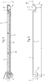
- Fig. 1 shows a sketch of an embodiment of a lamp 2 according to the invention, here in the form of a floor lamp.
- the luminaire 2 comprises a lamp base 21, a lamp post or a light column 22 and a lamp head 23.
- Fig. 2 shows a perspective view of the lamp head 23 obliquely from above
- Fig. 3 a view of the lamp head 23 obliquely from below.
- the lamp head 23 can be designed by the inventive design with suitable stability with a particularly low height.
- Fig. 4 shows a cross section through the lamp head 23.
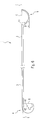
- the lamp head 23 comprises a heat sink 1, in a separated form in cross section in Fig. 5 outlined.
- the heat sink 1 is designed in particular as a profile part.
- Fig. 2 the corresponding profile axis p is indicated;
- Fig. 5 shows a cross section normal to the profile axis p.
- the heat sink 1 may be formed of metal, for example aluminum.
- thermally advantageous it is made up of only one piece formed. In terms of manufacturing technology, it can be designed, for example, as an extruded profile.
- the heat sink 1 has a plate-shaped region 3, which extends in a plane E.
- the lamp 2 is designed such that the heat sink 1 is oriented such that the plane E extends at least substantially horizontally when the lamp 2 or the lamp head 23 is in a state provided for operation. In principle, however, could also be provided a different orientation; For the sake of simplicity, it is assumed in this description that the plane E extends horizontally. This is particularly advantageous with respect to the cooling function.
- the plane E defines a first side u, here "below” or below the plane E and a second side o opposite thereto, here "above” or above the plane E.
- the heat sink 1 further comprises a first receiving area 4 for an example in Fig. 4 designated, first light source 5, which extends at least predominantly on the first side u and below the plane E.
- first receiving area 4 may be at a first edge side - with reference to the illustration in FIG Fig. 5 on the left edge side - of the plate-shaped area 3 connect to this.
- the heat sink 1 has a second receiving area 6 for a second light source 7.
- the second receiving region 6 also extends at least predominantly below the plane E or on the first side u of the plane E.
- the second receiving area 6 can adjoin to the second edge side opposite the first edge side, in this case to the right of the plate-shaped area 3.
- a first opening 8 for the passage of a light emitted by the first light source 5 is formed by the first receiving area 4.
- the first opening 8 extends below the plane E.
- the first opening 8 points to the second receiving area 6 Fig. 6 the areas around the two receiving areas 4, 6 are sketched slightly larger. In this case, the first opening 8 is indicated by a dotted line.
- the second receiving portion 6 is a, to the second side o or upwardly facing, second opening 9 for the passage of a light emitted from the second light source 7 is formed.
- the second receiving area 6 can be designed in such a way that the second opening 9 extends in the plane E or, more generally, parallel to the plane E.
- the light emitted by the second light source 7 can be reflected by the second opening 9 delivered above.
- the heat sink 1 is preferably further configured to hold a plate-shaped light guide 10, in such a way that the light guide 10 in the salary state between the first receiving area 4 and extends in the second receiving region 6, in particular parallel to the plane E, here below the level of the plate-shaped region 3.
- the design is such that the light emitted from the first light source 5 is irradiated into the light guide 10 and further through the downward facing surface 101 of the light guide 10 is discharged downward.
- the plate-shaped design of the light guide 10 can thus cause a large-area light output down.
- the first light source 5 LEDs 51 include, which are arranged on a circuit board 52 and in particular parallel to the profile axis p of the heat sink 1 in a row extend.
- a particularly planar support surface 41 for the circuit board 52 of the first light source 5 can be formed by the first receiving region 4.
- the support surface 41 may extend perpendicular to the plane E. This design is particularly suitable for efficient irradiation of the light emitted by the first light source 5, here the LEDs 51, into a narrow edge side 102 of the light guide 10.
- the light guide 10 preferably extends in a further plane E 'parallel to the plane E, wherein also the LEDs 51 of the first light source 51 extend in this further plane E '.
- the second light source 7 may extend in this further plane E ', whereby a total of a particularly small height of the heat sink 1 and thus also of the lamp head 23 is possible.
- the latter may have a screw 42, so that the board 52 of the first light source 5 by means of a screw 17 on or in the first receiving area 4 can be screwed.
- the second light source 7 LEDs 71 may have, which are arranged on a circuit board 72 and also extend in particular parallel to the profile axis p of the heat sink 1 in a row.
- a particularly planar support surface 11 for the second light source 7 is formed by the second receiving region 6, which extends obliquely in particular with respect to the plane E.
- the design may be such that a third plane E "is defined by the support surface 11, which encloses an angle ⁇ with the first-mentioned plane E which is between 20 ° and 70 °, preferably between 30 ° and 50 °.
- the second receiving space 6 may have a reflecting surface area for reflecting the light emitted by the second light source 7, so that a particularly efficient light emission is supported.
- the described configuration of the heat sink 1 makes it possible, in particular, for the two light sources 5, 7 and the light guide 10 to be located essentially in one plane, in this case in the further plane E ', whereby a particularly low overall height is made possible.
- the heat sink 1 may be designed such that its height or extent h normal to the plane E is less than 20 mm. In this case, the heat sink 1 can make suitable torsion resistant.
- the design is furthermore such that the following applies for the ratio between the width b and the extent h considered normal to the profile axis p: b / h> 5, in particular b / h> 10.
- This makes it possible, in particular, for a very flat appearance of the lamp head 23 to achieve a particularly large-area light output down.
- the lamp 2 is preferably designed so that an outer surface 12, here an upwardly facing o outer surface 12 of the lamp is formed by the plate-shaped portion 3 of the heat sink 1.
- a cover element as usual in the aforementioned prior art, is therefore not required here.
- a quasi “housing” of the lamp 2 may be formed in the Sense that all other components of the lamp head 23 are held held on the heat sink 1.
- FIGS. 2 and 3 shows an advantageous advantageous by the second receiving portion 6 of the heat sink 1, an edge portion 13 of the lamp 2 is formed, preferably by the first receiving portion 4 of the heat sink 1, a further edge portion 14 of the lamp 2 is formed.
- the light 2 is designed such that the light emitted by the first light source 5 is emitted from the light 2 after deflection by the light guide 10 down to produce a direct illumination.
- the light generated by the second light source 7 is emitted upward or obliquely above to produce an indirect illumination.
- a curved portion 24 of the light column 22 may be provided, which - as for example from the FIGS. 2, 3 and 7 shows - holding the heat sink 1 from above and from below gripping.
- the bent portion 24 may, for example, as in Fig. 1 be shown S-shaped or, according to a variant, as in the FIGS. 2, 3 and 7 shown, bent in one direction only.
- the lamp further comprises a translucent cover 15, which is arranged covering the second opening 9.
- the cover 15 may be designed as a light-influencing element, for example as a lens, or it may be provided in addition to the cover 15, an optically active element.
- the cover 15 may also be designed curved upwards.
- the cover 15 is also advantageous with respect to electrostatic discharge protection and heat contact protection.
- An optical influencing element 19 may also be provided for optically influencing the light emitted by the first light source 5, for example in FIG Shape of a plate-shaped element, which is arranged under the light guide 10.
- this may be a lens.
- the second receiving region 6 has a projection 61, through which a support surface for the optical waveguide 10 or the optical influencing element 19.
- the lamp further comprises an end cap 16, which is arranged on a, the first receiving portion 4 and the second receiving portion 6 contacting edge side of the heat sink 1, in particular one, with respect to the profile axis p of the heat sink 1 normally oriented edge side, for example plugged ,
- the end cap 16 may advantageously also form a support surface for supporting a further component, for example for mounting the light guide plate 10, the cover 15 or another optically active element.
- a corresponding further end cap can be provided on the opposite edge side opposite thereto.
- the design of the heat sink 1 makes it possible to achieve a particularly suitable dissipation of the heat generated by the two light sources 5, 7 during operation of the luminaire.
- the dissipation of this heat can be achieved in particular by the fact that the heat sink 1 over its entire surface with its plate-shaped portion 3 at the top of the light guide 10 from the intended for attachment to the light column 22 area or from the other edge portion 14 of the lamp to the opposite lying edge region 13 of the lamp extends.
- the two light sources 5, 7 are thus substantially only each edge on the plate-shaped portion 3, but is still achieved by the one-piece design of the heat sink 1, a good heat conduction to the outer surface 12, so that an efficient heat transfer to the environment of the lamp is possible.
- the aforementioned edge regions 13, 14 also fulfill a protective function for the optics.
- the two light sources 5, 7 are fastened in the receiving areas 4, 6 in a first step second step of the light guide 10 and optionally further optical elements and the cover 15 are inserted and in a third step, the end caps are placed.
- the further light source can also be designed as an LED board, so that, for example, two boards with LEDs are arranged in the second receiving area 6 accordingly. It may alternatively be provided on both sides populated with LEDs board.
- the second receiving area - with reference to the representation of the Fig. 4 also integrated in the left edge area.
Landscapes
- Engineering & Computer Science (AREA)
- General Engineering & Computer Science (AREA)
- Arrangement Of Elements, Cooling, Sealing, Or The Like Of Lighting Devices (AREA)
- Non-Portable Lighting Devices Or Systems Thereof (AREA)
Claims (15)
- Dissipateur thermique (1) pour un luminaire (2), comportant- une zone (3) en forme de plaque, qui s'étend dans un plan (E) de telle sorte qu'en rapport au plan (E), un premier côté (u) et un deuxième côté opposé à celui-ci soient immobilisés,- une première zone de logement (4) pour une première source lumineuse (5), qui s'étend au moins majoritairement sur le premier côté (u) du plan (E),- une deuxième zone de logement (6) pour une deuxième source lumineuse (7), qui s'étend au moins majoritairement sur le premier côté (u) du plan (E),à travers la première zone de logement (4) étant ménagé un premier orifice (8) s'étendant sur le premier côté (u), pour le passage d'une lumière émise par la première source lumineuse (5) et à travers la deuxième zone de logement (6) étant ménagé un deuxième orifice (9), dirigé vers le deuxième côté (o) pour le passage d'une lumière émise par la deuxième source lumineuse (7),
caractérisé
en ce que le dissipateur thermique est conçu par ailleurs pour maintenir un conducteur optique (10) en forme de plaque, de telle sorte que le conducteur optique (10), lorsqu'il est maintenu, s'étende entre la première zone de logement (4) et la deuxième zone de logement (6). - Dissipateur thermique selon la revendication 1, caractérisé
en ce que la deuxième zone de logement (6) est conçue de telle sorte que le deuxième orifice (9) s'étende dans le plan (E) ou à la parallèle du plan (E). - Dissipateur thermique (1) selon la revendication 1 ou 2,
caractérisé
en ce qu'il est conçu sous la forme d'un corps profilé, notamment d'un profilé extrudé. - Dissipateur thermique (1) selon l'une quelconque des revendications précédentes,
caractérisé
en ce qu'il est composé de métal, par exemple d'aluminium. - Dissipateur thermique (1) selon l'une quelconque des revendications précédentes,
caractérisé
en ce qu'il est formé en une unique pièce. - Dissipateur thermique (1) selon l'une quelconque des revendications précédentes,
caractérisé
en ce que pour maintenir le conducteur optique (10) en forme de plaque, le dissipateur thermique est conçu de telle sorte que lorsqu'il est maintenu, le conducteur optique (10) s'étende entre la première zone de logement (4) et la deuxième zone de logement (6), à la parallèle du plan (E). - Dissipateur thermique (1) selon l'une quelconque des revendications précédentes,
caractérisé
en ce que par la deuxième zone de logement (6) est formée une surface d'appui (11) pour la deuxième source lumineuse (7), qui s'étend en oblique par rapport au plan (E). - Dissipateur thermique (1) selon l'une quelconque des revendications précédentes,
caractérisé
en ce que son extension (h) à la normale du plan (E) est inférieure à 20 mm. - Luminaire (2) comportant- un dissipateur thermique (1) selon l'une quelconque des revendications précédentes.
- Luminaire (2) selon la revendication 9,
caractérisé
en ce que le luminaire (2) est conçu de telle sorte, que lorsque le luminaire (2) est en fonctionnement, le dissipateur thermique (1) est orienté de telle manière que le premier côté (u) soit dirigé vers le bas et le deuxième côté (o) vers le haut. - Luminaire (2) selon la revendication 9 ou 10,
caractérisé
en ce que le luminaire (2) est conçu de telle sorte, que par la zone (3) en forme de plaque du dissipateur thermique (1), il soit créé une surface extérieure (12) du luminaire (2). - Luminaire (2) selon l'une quelconque des revendications 9 à 11,
caractérisé
en ce que par la deuxième zone de logement (6) du dissipateur thermique (1), il est créé une zone marginale (13) du luminaire (2), sachant que de préférence, par la première zone de logement (4) du dissipateur thermique (1) il est créé une zone marginale (14) supplémentaire du luminaire (2). - Luminaire (2) selon l'une quelconque des revendications 9 à 12,
caractérisé
en ce que la première source lumineuse (5) est placée dans la première zone de logement (4) et la deuxième source lumineuse (7) est placée dans la deuxième zone de logement (6), la lumière émise par la première source lumineuse (5) étant restituée par le luminaire (2), notamment après avoir été déviée par le conducteur optique (10) maintenu à l'aide du dissipateur thermique (1) vers le bas, pour créer un éclairage direct et la lumière générée par la deuxième source lumineuse (7) étant restituée vers le haut, pour créer un éclairage indirect. - Luminaire (2) selon l'une quelconque des revendications 9 à 13,
caractérisé par- un couvercle (15) translucide, qui est placé en recouvrant le deuxième orifice (9), le couvercle (15) étant conçu de préférence sous la forme d'un élément influençant la lumière. - Luminaire (2) selon l'une quelconque des revendications 9 à 14,
caractérisé par- une calotte d'extrémité (16), qui est placée, par exemple emboîtée, sur une face de bordure du dissipateur thermique (1), qui touche la première zone de logement (4) et la deuxième zone de logement (6).
Applications Claiming Priority (1)
| Application Number | Priority Date | Filing Date | Title |
|---|---|---|---|
| DE202016100435.7U DE202016100435U1 (de) | 2016-01-29 | 2016-01-29 | Kühlkörper für eine Leuchte, sowie Leuchte mit einem solchen Kühlkörper |
Publications (2)
| Publication Number | Publication Date |
|---|---|
| EP3199864A1 EP3199864A1 (fr) | 2017-08-02 |
| EP3199864B1 true EP3199864B1 (fr) | 2018-08-29 |
Family
ID=57914822
Family Applications (1)
| Application Number | Title | Priority Date | Filing Date |
|---|---|---|---|
| EP17153461.3A Not-in-force EP3199864B1 (fr) | 2016-01-29 | 2017-01-27 | Corps de refroidissement pour un éclairage et éclairage comprenant un tel corps de refroidissement |
Country Status (3)
| Country | Link |
|---|---|
| EP (1) | EP3199864B1 (fr) |
| AT (1) | AT16563U1 (fr) |
| DE (1) | DE202016100435U1 (fr) |
Families Citing this family (1)
| Publication number | Priority date | Publication date | Assignee | Title |
|---|---|---|---|---|
| CN110160014B (zh) * | 2019-05-23 | 2024-04-26 | 欧普照明股份有限公司 | 一种照明灯具 |
Family Cites Families (7)
| Publication number | Priority date | Publication date | Assignee | Title |
|---|---|---|---|---|
| DE102008015728A1 (de) * | 2008-03-26 | 2009-10-01 | Zumtobel Lighting Gmbh | Leuchte mit einer sich von einem Leuchtenfuß nach oben erstreckenden Leuchtensäule |
| DE102009001170A1 (de) * | 2009-02-26 | 2010-09-02 | Evonik Röhm Gmbh | Leuchte für Beleuchtungszwecke, deren Einfassung gleichzeitig als Kühlkörper für das LED-Leuchtmittel fungiert |
| DE202010003751U1 (de) * | 2010-03-17 | 2011-07-26 | Zumtobel Lighting Gmbh | Leuchte zur Erzeugung einer veränderbaren indirekten Beleuchtung |
| DE102010044353A1 (de) * | 2010-09-03 | 2012-03-08 | Herbert Waldmann Gmbh & Co. Kg | Steh- oder Tischleuchte |
| DE102011015161A1 (de) * | 2011-03-26 | 2012-05-24 | Schott Ag | LED-Beleuchtungseinrichtung |
| DE102012102973A1 (de) * | 2012-04-05 | 2013-10-10 | Siteco Beleuchtungstechnik Gmbh | Leuchte mit integriertem Kühlkörper |
| DE102014106342B4 (de) * | 2014-05-07 | 2023-07-27 | HELLA GmbH & Co. KGaA | Lichtmodul für einen Scheinwerfer eines Fahrzeugs |
-
2016
- 2016-01-29 DE DE202016100435.7U patent/DE202016100435U1/de not_active Expired - Lifetime
- 2016-07-14 AT ATGM177/2016U patent/AT16563U1/de not_active IP Right Cessation
-
2017
- 2017-01-27 EP EP17153461.3A patent/EP3199864B1/fr not_active Not-in-force
Also Published As
| Publication number | Publication date |
|---|---|
| DE202016100435U1 (de) | 2017-05-05 |
| AT16563U1 (de) | 2020-01-15 |
| EP3199864A1 (fr) | 2017-08-02 |
Similar Documents
| Publication | Publication Date | Title |
|---|---|---|
| DE102012222184B4 (de) | Leuchte mit Luftleitflächen | |
| DE102008063369B4 (de) | Leuchte und Modulsystem für Leuchten | |
| EP2539629B1 (fr) | Lampe intégrée comportant un corps de base et un réflecteur en forme de dôme | |
| WO2010112595A1 (fr) | Dispositif lumineux et luminaire présentant un tel dispositif lumineux | |
| EP2322847B1 (fr) | Plafonnier réglable à DEL | |
| DE202009017522U1 (de) | LED-Einbauleuchte mit Kühlkörper | |
| CH709009B1 (de) | Befestigung einer Leiterplatte und einer Optik einer Leuchte. | |
| EP2796770B1 (fr) | Éclairage doté d'une unité de production de lumière et d'un élément de cadre | |
| WO2015132226A1 (fr) | Luminaire comprenant des moyens lumineux pour une émission de lumière directe et indirecte | |
| EP2392854B1 (fr) | Lampe destinée à la production d'un éclairage indirect modifiable | |
| DE202013010406U1 (de) | LED-Leuchte | |
| EP2994693B1 (fr) | Élément de recouvrement pour luminaire surfacique | |
| DE102011017725A1 (de) | Anordnung zur Lichtabgabe | |
| EP3199864A1 (fr) | Corps de refroidissement pour un éclairage et éclairage comprenant un tel corps de refroidissement | |
| EP2824381B1 (fr) | Éclairage doté d'un élément supplémentaire en forme d'élément d'éclairage de secours et/ou d'un élément d'émission et de réception destiné à émettre et/ou à recevoir le rayonnement électromagnétique | |
| DE102017110899A1 (de) | OLED-Leuchte | |
| DE102017104596A1 (de) | Beleuchtungskörper | |
| EP2175188B1 (fr) | Eclairage | |
| DE202015106221U1 (de) | LED-Leuchte mit einem Basiselement und einem stabförmigen Element | |
| DE202015101870U1 (de) | Optisches System sowie Anordnung zur Lichtabgabe | |
| DE102019102056B4 (de) | Reflektorlampe mit dreidimensionaler Lightengine | |
| DE202008017182U1 (de) | Leuchte | |
| EP2711622B1 (fr) | Lampe dotée d'une protection contre le contact | |
| DE102009058308B4 (de) | Reflektor für Leuchten mit Ellipsoid-Facetten | |
| EP3293443A1 (fr) | Unité optique pour un éclairage |
Legal Events
| Date | Code | Title | Description |
|---|---|---|---|
| PUAI | Public reference made under article 153(3) epc to a published international application that has entered the european phase |
Free format text: ORIGINAL CODE: 0009012 |
|
| STAA | Information on the status of an ep patent application or granted ep patent |
Free format text: STATUS: THE APPLICATION HAS BEEN PUBLISHED |
|
| AK | Designated contracting states |
Kind code of ref document: A1 Designated state(s): AL AT BE BG CH CY CZ DE DK EE ES FI FR GB GR HR HU IE IS IT LI LT LU LV MC MK MT NL NO PL PT RO RS SE SI SK SM TR |
|
| AX | Request for extension of the european patent |
Extension state: BA ME |
|
| STAA | Information on the status of an ep patent application or granted ep patent |
Free format text: STATUS: REQUEST FOR EXAMINATION WAS MADE |
|
| 17P | Request for examination filed |
Effective date: 20171205 |
|
| RBV | Designated contracting states (corrected) |
Designated state(s): AL AT BE BG CH CY CZ DE DK EE ES FI FR GB GR HR HU IE IS IT LI LT LU LV MC MK MT NL NO PL PT RO RS SE SI SK SM TR |
|
| GRAP | Despatch of communication of intention to grant a patent |
Free format text: ORIGINAL CODE: EPIDOSNIGR1 |
|
| STAA | Information on the status of an ep patent application or granted ep patent |
Free format text: STATUS: GRANT OF PATENT IS INTENDED |
|
| RIC1 | Information provided on ipc code assigned before grant |
Ipc: F21V 15/01 20060101ALI20180309BHEP Ipc: F21Y 113/20 20160101ALN20180309BHEP Ipc: F21V 7/00 20060101ALI20180309BHEP Ipc: F21S 6/00 20060101AFI20180309BHEP Ipc: F21V 21/116 20060101ALI20180309BHEP Ipc: F21V 29/70 20150101ALI20180309BHEP |
|
| RIC1 | Information provided on ipc code assigned before grant |
Ipc: F21V 15/01 20060101ALI20180319BHEP Ipc: F21V 21/116 20060101ALI20180319BHEP Ipc: F21Y 113/20 20160101ALN20180319BHEP Ipc: F21S 6/00 20060101AFI20180319BHEP Ipc: F21V 29/70 20150101ALI20180319BHEP Ipc: F21V 7/00 20060101ALI20180319BHEP |
|
| INTG | Intention to grant announced |
Effective date: 20180413 |
|
| GRAS | Grant fee paid |
Free format text: ORIGINAL CODE: EPIDOSNIGR3 |
|
| GRAA | (expected) grant |
Free format text: ORIGINAL CODE: 0009210 |
|
| STAA | Information on the status of an ep patent application or granted ep patent |
Free format text: STATUS: THE PATENT HAS BEEN GRANTED |
|
| AK | Designated contracting states |
Kind code of ref document: B1 Designated state(s): AL AT BE BG CH CY CZ DE DK EE ES FI FR GB GR HR HU IE IS IT LI LT LU LV MC MK MT NL NO PL PT RO RS SE SI SK SM TR |
|
| REG | Reference to a national code |
Ref country code: GB Ref legal event code: FG4D Free format text: NOT ENGLISH |
|
| REG | Reference to a national code |
Ref country code: CH Ref legal event code: EP |
|
| REG | Reference to a national code |
Ref country code: AT Ref legal event code: REF Ref document number: 1035542 Country of ref document: AT Kind code of ref document: T Effective date: 20180915 |
|
| REG | Reference to a national code |
Ref country code: IE Ref legal event code: FG4D Free format text: LANGUAGE OF EP DOCUMENT: GERMAN |
|
| REG | Reference to a national code |
Ref country code: DE Ref legal event code: R096 Ref document number: 502017000129 Country of ref document: DE |
|
| REG | Reference to a national code |
Ref country code: NL Ref legal event code: MP Effective date: 20180829 |
|
| REG | Reference to a national code |
Ref country code: LT Ref legal event code: MG4D |
|
| PG25 | Lapsed in a contracting state [announced via postgrant information from national office to epo] |
Ref country code: BG Free format text: LAPSE BECAUSE OF FAILURE TO SUBMIT A TRANSLATION OF THE DESCRIPTION OR TO PAY THE FEE WITHIN THE PRESCRIBED TIME-LIMIT Effective date: 20181129 Ref country code: IS Free format text: LAPSE BECAUSE OF FAILURE TO SUBMIT A TRANSLATION OF THE DESCRIPTION OR TO PAY THE FEE WITHIN THE PRESCRIBED TIME-LIMIT Effective date: 20181229 Ref country code: NO Free format text: LAPSE BECAUSE OF FAILURE TO SUBMIT A TRANSLATION OF THE DESCRIPTION OR TO PAY THE FEE WITHIN THE PRESCRIBED TIME-LIMIT Effective date: 20181129 Ref country code: LT Free format text: LAPSE BECAUSE OF FAILURE TO SUBMIT A TRANSLATION OF THE DESCRIPTION OR TO PAY THE FEE WITHIN THE PRESCRIBED TIME-LIMIT Effective date: 20180829 Ref country code: FI Free format text: LAPSE BECAUSE OF FAILURE TO SUBMIT A TRANSLATION OF THE DESCRIPTION OR TO PAY THE FEE WITHIN THE PRESCRIBED TIME-LIMIT Effective date: 20180829 Ref country code: RS Free format text: LAPSE BECAUSE OF FAILURE TO SUBMIT A TRANSLATION OF THE DESCRIPTION OR TO PAY THE FEE WITHIN THE PRESCRIBED TIME-LIMIT Effective date: 20180829 Ref country code: GR Free format text: LAPSE BECAUSE OF FAILURE TO SUBMIT A TRANSLATION OF THE DESCRIPTION OR TO PAY THE FEE WITHIN THE PRESCRIBED TIME-LIMIT Effective date: 20181130 Ref country code: NL Free format text: LAPSE BECAUSE OF FAILURE TO SUBMIT A TRANSLATION OF THE DESCRIPTION OR TO PAY THE FEE WITHIN THE PRESCRIBED TIME-LIMIT Effective date: 20180829 Ref country code: SE Free format text: LAPSE BECAUSE OF FAILURE TO SUBMIT A TRANSLATION OF THE DESCRIPTION OR TO PAY THE FEE WITHIN THE PRESCRIBED TIME-LIMIT Effective date: 20180829 |
|
| PG25 | Lapsed in a contracting state [announced via postgrant information from national office to epo] |
Ref country code: LV Free format text: LAPSE BECAUSE OF FAILURE TO SUBMIT A TRANSLATION OF THE DESCRIPTION OR TO PAY THE FEE WITHIN THE PRESCRIBED TIME-LIMIT Effective date: 20180829 Ref country code: AL Free format text: LAPSE BECAUSE OF FAILURE TO SUBMIT A TRANSLATION OF THE DESCRIPTION OR TO PAY THE FEE WITHIN THE PRESCRIBED TIME-LIMIT Effective date: 20180829 Ref country code: HR Free format text: LAPSE BECAUSE OF FAILURE TO SUBMIT A TRANSLATION OF THE DESCRIPTION OR TO PAY THE FEE WITHIN THE PRESCRIBED TIME-LIMIT Effective date: 20180829 |
|
| PG25 | Lapsed in a contracting state [announced via postgrant information from national office to epo] |
Ref country code: PL Free format text: LAPSE BECAUSE OF FAILURE TO SUBMIT A TRANSLATION OF THE DESCRIPTION OR TO PAY THE FEE WITHIN THE PRESCRIBED TIME-LIMIT Effective date: 20180829 Ref country code: ES Free format text: LAPSE BECAUSE OF FAILURE TO SUBMIT A TRANSLATION OF THE DESCRIPTION OR TO PAY THE FEE WITHIN THE PRESCRIBED TIME-LIMIT Effective date: 20180829 Ref country code: CZ Free format text: LAPSE BECAUSE OF FAILURE TO SUBMIT A TRANSLATION OF THE DESCRIPTION OR TO PAY THE FEE WITHIN THE PRESCRIBED TIME-LIMIT Effective date: 20180829 Ref country code: RO Free format text: LAPSE BECAUSE OF FAILURE TO SUBMIT A TRANSLATION OF THE DESCRIPTION OR TO PAY THE FEE WITHIN THE PRESCRIBED TIME-LIMIT Effective date: 20180829 Ref country code: IT Free format text: LAPSE BECAUSE OF FAILURE TO SUBMIT A TRANSLATION OF THE DESCRIPTION OR TO PAY THE FEE WITHIN THE PRESCRIBED TIME-LIMIT Effective date: 20180829 Ref country code: EE Free format text: LAPSE BECAUSE OF FAILURE TO SUBMIT A TRANSLATION OF THE DESCRIPTION OR TO PAY THE FEE WITHIN THE PRESCRIBED TIME-LIMIT Effective date: 20180829 |
|
| PG25 | Lapsed in a contracting state [announced via postgrant information from national office to epo] |
Ref country code: SK Free format text: LAPSE BECAUSE OF FAILURE TO SUBMIT A TRANSLATION OF THE DESCRIPTION OR TO PAY THE FEE WITHIN THE PRESCRIBED TIME-LIMIT Effective date: 20180829 Ref country code: DK Free format text: LAPSE BECAUSE OF FAILURE TO SUBMIT A TRANSLATION OF THE DESCRIPTION OR TO PAY THE FEE WITHIN THE PRESCRIBED TIME-LIMIT Effective date: 20180829 Ref country code: SM Free format text: LAPSE BECAUSE OF FAILURE TO SUBMIT A TRANSLATION OF THE DESCRIPTION OR TO PAY THE FEE WITHIN THE PRESCRIBED TIME-LIMIT Effective date: 20180829 |
|
| REG | Reference to a national code |
Ref country code: DE Ref legal event code: R097 Ref document number: 502017000129 Country of ref document: DE |
|
| PLBE | No opposition filed within time limit |
Free format text: ORIGINAL CODE: 0009261 |
|
| STAA | Information on the status of an ep patent application or granted ep patent |
Free format text: STATUS: NO OPPOSITION FILED WITHIN TIME LIMIT |
|
| 26N | No opposition filed |
Effective date: 20190531 |
|
| PG25 | Lapsed in a contracting state [announced via postgrant information from national office to epo] |
Ref country code: SI Free format text: LAPSE BECAUSE OF FAILURE TO SUBMIT A TRANSLATION OF THE DESCRIPTION OR TO PAY THE FEE WITHIN THE PRESCRIBED TIME-LIMIT Effective date: 20180829 Ref country code: MC Free format text: LAPSE BECAUSE OF FAILURE TO SUBMIT A TRANSLATION OF THE DESCRIPTION OR TO PAY THE FEE WITHIN THE PRESCRIBED TIME-LIMIT Effective date: 20180829 |
|
| PG25 | Lapsed in a contracting state [announced via postgrant information from national office to epo] |
Ref country code: LU Free format text: LAPSE BECAUSE OF NON-PAYMENT OF DUE FEES Effective date: 20190127 |
|
| REG | Reference to a national code |
Ref country code: BE Ref legal event code: MM Effective date: 20190131 |
|
| REG | Reference to a national code |
Ref country code: IE Ref legal event code: MM4A |
|
| PG25 | Lapsed in a contracting state [announced via postgrant information from national office to epo] |
Ref country code: BE Free format text: LAPSE BECAUSE OF NON-PAYMENT OF DUE FEES Effective date: 20190131 |
|
| PG25 | Lapsed in a contracting state [announced via postgrant information from national office to epo] |
Ref country code: IE Free format text: LAPSE BECAUSE OF NON-PAYMENT OF DUE FEES Effective date: 20190127 |
|
| PG25 | Lapsed in a contracting state [announced via postgrant information from national office to epo] |
Ref country code: TR Free format text: LAPSE BECAUSE OF FAILURE TO SUBMIT A TRANSLATION OF THE DESCRIPTION OR TO PAY THE FEE WITHIN THE PRESCRIBED TIME-LIMIT Effective date: 20180829 |
|
| PG25 | Lapsed in a contracting state [announced via postgrant information from national office to epo] |
Ref country code: PT Free format text: LAPSE BECAUSE OF FAILURE TO SUBMIT A TRANSLATION OF THE DESCRIPTION OR TO PAY THE FEE WITHIN THE PRESCRIBED TIME-LIMIT Effective date: 20181229 Ref country code: MT Free format text: LAPSE BECAUSE OF FAILURE TO SUBMIT A TRANSLATION OF THE DESCRIPTION OR TO PAY THE FEE WITHIN THE PRESCRIBED TIME-LIMIT Effective date: 20180829 |
|
| REG | Reference to a national code |
Ref country code: CH Ref legal event code: PL |
|
| PG25 | Lapsed in a contracting state [announced via postgrant information from national office to epo] |
Ref country code: LI Free format text: LAPSE BECAUSE OF NON-PAYMENT OF DUE FEES Effective date: 20200131 Ref country code: CH Free format text: LAPSE BECAUSE OF NON-PAYMENT OF DUE FEES Effective date: 20200131 |
|
| PG25 | Lapsed in a contracting state [announced via postgrant information from national office to epo] |
Ref country code: CY Free format text: LAPSE BECAUSE OF FAILURE TO SUBMIT A TRANSLATION OF THE DESCRIPTION OR TO PAY THE FEE WITHIN THE PRESCRIBED TIME-LIMIT Effective date: 20180829 |
|
| PG25 | Lapsed in a contracting state [announced via postgrant information from national office to epo] |
Ref country code: HU Free format text: LAPSE BECAUSE OF FAILURE TO SUBMIT A TRANSLATION OF THE DESCRIPTION OR TO PAY THE FEE WITHIN THE PRESCRIBED TIME-LIMIT; INVALID AB INITIO Effective date: 20170127 |
|
| REG | Reference to a national code |
Ref country code: DE Ref legal event code: R084 Ref document number: 502017000129 Country of ref document: DE |
|
| PG25 | Lapsed in a contracting state [announced via postgrant information from national office to epo] |
Ref country code: MK Free format text: LAPSE BECAUSE OF FAILURE TO SUBMIT A TRANSLATION OF THE DESCRIPTION OR TO PAY THE FEE WITHIN THE PRESCRIBED TIME-LIMIT Effective date: 20180829 |
|
| REG | Reference to a national code |
Ref country code: AT Ref legal event code: MM01 Ref document number: 1035542 Country of ref document: AT Kind code of ref document: T Effective date: 20220127 |
|
| PG25 | Lapsed in a contracting state [announced via postgrant information from national office to epo] |
Ref country code: AT Free format text: LAPSE BECAUSE OF NON-PAYMENT OF DUE FEES Effective date: 20220127 |
|
| PGFP | Annual fee paid to national office [announced via postgrant information from national office to epo] |
Ref country code: FR Payment date: 20230124 Year of fee payment: 7 |
|
| PGFP | Annual fee paid to national office [announced via postgrant information from national office to epo] |
Ref country code: GB Payment date: 20230124 Year of fee payment: 7 |
|
| P01 | Opt-out of the competence of the unified patent court (upc) registered |
Effective date: 20230530 |
|
| PGFP | Annual fee paid to national office [announced via postgrant information from national office to epo] |
Ref country code: DE Payment date: 20240129 Year of fee payment: 8 |
|
| GBPC | Gb: european patent ceased through non-payment of renewal fee |
Effective date: 20240127 |
|
| PG25 | Lapsed in a contracting state [announced via postgrant information from national office to epo] |
Ref country code: GB Free format text: LAPSE BECAUSE OF NON-PAYMENT OF DUE FEES Effective date: 20240127 |
|
| PG25 | Lapsed in a contracting state [announced via postgrant information from national office to epo] |
Ref country code: FR Free format text: LAPSE BECAUSE OF NON-PAYMENT OF DUE FEES Effective date: 20240131 |
|
| PG25 | Lapsed in a contracting state [announced via postgrant information from national office to epo] |
Ref country code: GB Free format text: LAPSE BECAUSE OF NON-PAYMENT OF DUE FEES Effective date: 20240127 Ref country code: FR Free format text: LAPSE BECAUSE OF NON-PAYMENT OF DUE FEES Effective date: 20240131 |
|
| REG | Reference to a national code |
Ref country code: DE Ref legal event code: R119 Ref document number: 502017000129 Country of ref document: DE |
|
| PG25 | Lapsed in a contracting state [announced via postgrant information from national office to epo] |
Ref country code: DE Free format text: LAPSE BECAUSE OF NON-PAYMENT OF DUE FEES Effective date: 20250801 |