EP3199767B1 - Motoranordnung mit turbinenstützgehäuse - Google Patents
Motoranordnung mit turbinenstützgehäuse Download PDFInfo
- Publication number
- EP3199767B1 EP3199767B1 EP17153701.2A EP17153701A EP3199767B1 EP 3199767 B1 EP3199767 B1 EP 3199767B1 EP 17153701 A EP17153701 A EP 17153701A EP 3199767 B1 EP3199767 B1 EP 3199767B1
- Authority
- EP
- European Patent Office
- Prior art keywords
- turbine
- inlet
- exhaust
- engine
- casing
- Prior art date
- Legal status (The legal status is an assumption and is not a legal conclusion. Google has not performed a legal analysis and makes no representation as to the accuracy of the status listed.)
- Active
Links
- 238000006243 chemical reaction Methods 0.000 claims description 26
- 238000002485 combustion reaction Methods 0.000 claims description 15
- 239000012530 fluid Substances 0.000 claims description 15
- 238000004891 communication Methods 0.000 claims description 13
- 230000008859 change Effects 0.000 claims description 4
- 239000013256 coordination polymer Substances 0.000 claims description 2
- 150000001875 compounds Chemical class 0.000 description 10
- 239000000446 fuel Substances 0.000 description 8
- 239000007789 gas Substances 0.000 description 7
- 230000033001 locomotion Effects 0.000 description 7
- 230000002093 peripheral effect Effects 0.000 description 6
- 230000000712 assembly Effects 0.000 description 4
- 238000000429 assembly Methods 0.000 description 4
- 238000009423 ventilation Methods 0.000 description 4
- 230000001133 acceleration Effects 0.000 description 3
- 230000006835 compression Effects 0.000 description 3
- 238000007906 compression Methods 0.000 description 3
- 239000002826 coolant Substances 0.000 description 3
- 239000000203 mixture Substances 0.000 description 3
- 230000009467 reduction Effects 0.000 description 3
- 230000003068 static effect Effects 0.000 description 3
- 238000001816 cooling Methods 0.000 description 2
- 238000007667 floating Methods 0.000 description 2
- 238000012986 modification Methods 0.000 description 2
- 230000004048 modification Effects 0.000 description 2
- 238000011144 upstream manufacturing Methods 0.000 description 2
- OKTJSMMVPCPJKN-UHFFFAOYSA-N Carbon Chemical compound [C] OKTJSMMVPCPJKN-UHFFFAOYSA-N 0.000 description 1
- 230000008901 benefit Effects 0.000 description 1
- 239000002551 biofuel Substances 0.000 description 1
- 230000005540 biological transmission Effects 0.000 description 1
- 238000005219 brazing Methods 0.000 description 1
- 229910052799 carbon Inorganic materials 0.000 description 1
- 230000000295 complement effect Effects 0.000 description 1
- 230000008878 coupling Effects 0.000 description 1
- 238000010168 coupling process Methods 0.000 description 1
- 238000005859 coupling reaction Methods 0.000 description 1
- -1 diesel Substances 0.000 description 1
- 238000007599 discharging Methods 0.000 description 1
- 238000006073 displacement reaction Methods 0.000 description 1
- KVIPHDKUOLVVQN-UHFFFAOYSA-N ethene;hydrate Chemical group O.C=C KVIPHDKUOLVVQN-UHFFFAOYSA-N 0.000 description 1
- 238000004880 explosion Methods 0.000 description 1
- 238000000605 extraction Methods 0.000 description 1
- 238000002347 injection Methods 0.000 description 1
- 239000007924 injection Substances 0.000 description 1
- 239000003350 kerosene Substances 0.000 description 1
- 239000000463 material Substances 0.000 description 1
- 238000011084 recovery Methods 0.000 description 1
- 230000002441 reversible effect Effects 0.000 description 1
- 238000007789 sealing Methods 0.000 description 1
- 238000000926 separation method Methods 0.000 description 1
- 230000000087 stabilizing effect Effects 0.000 description 1
- 238000003466 welding Methods 0.000 description 1
Images


Classifications
-
- F—MECHANICAL ENGINEERING; LIGHTING; HEATING; WEAPONS; BLASTING
- F01—MACHINES OR ENGINES IN GENERAL; ENGINE PLANTS IN GENERAL; STEAM ENGINES
- F01C—ROTARY-PISTON OR OSCILLATING-PISTON MACHINES OR ENGINES
- F01C21/00—Component parts, details or accessories not provided for in groups F01C1/00 - F01C20/00
- F01C21/10—Outer members for co-operation with rotary pistons; Casings
-
- F—MECHANICAL ENGINEERING; LIGHTING; HEATING; WEAPONS; BLASTING
- F01—MACHINES OR ENGINES IN GENERAL; ENGINE PLANTS IN GENERAL; STEAM ENGINES
- F01C—ROTARY-PISTON OR OSCILLATING-PISTON MACHINES OR ENGINES
- F01C1/00—Rotary-piston machines or engines
- F01C1/22—Rotary-piston machines or engines of internal-axis type with equidirectional movement of co-operating members at the points of engagement, or with one of the co-operating members being stationary, the inner member having more teeth or tooth- equivalents than the outer member
-
- F—MECHANICAL ENGINEERING; LIGHTING; HEATING; WEAPONS; BLASTING
- F01—MACHINES OR ENGINES IN GENERAL; ENGINE PLANTS IN GENERAL; STEAM ENGINES
- F01C—ROTARY-PISTON OR OSCILLATING-PISTON MACHINES OR ENGINES
- F01C11/00—Combinations of two or more machines or engines, each being of rotary-piston or oscillating-piston type
- F01C11/006—Combinations of two or more machines or engines, each being of rotary-piston or oscillating-piston type of dissimilar working principle
- F01C11/008—Combinations of two or more machines or engines, each being of rotary-piston or oscillating-piston type of dissimilar working principle and of complementary function, e.g. internal combustion engine with supercharger
-
- F—MECHANICAL ENGINEERING; LIGHTING; HEATING; WEAPONS; BLASTING
- F01—MACHINES OR ENGINES IN GENERAL; ENGINE PLANTS IN GENERAL; STEAM ENGINES
- F01D—NON-POSITIVE DISPLACEMENT MACHINES OR ENGINES, e.g. STEAM TURBINES
- F01D9/00—Stators
- F01D9/02—Nozzles; Nozzle boxes; Stator blades; Guide conduits, e.g. individual nozzles
- F01D9/026—Scrolls for radial machines or engines
-
- F—MECHANICAL ENGINEERING; LIGHTING; HEATING; WEAPONS; BLASTING
- F01—MACHINES OR ENGINES IN GENERAL; ENGINE PLANTS IN GENERAL; STEAM ENGINES
- F01N—GAS-FLOW SILENCERS OR EXHAUST APPARATUS FOR MACHINES OR ENGINES IN GENERAL; GAS-FLOW SILENCERS OR EXHAUST APPARATUS FOR INTERNAL COMBUSTION ENGINES
- F01N13/00—Exhaust or silencing apparatus characterised by constructional features ; Exhaust or silencing apparatus, or parts thereof, having pertinent characteristics not provided for in, or of interest apart from, groups F01N1/00 - F01N5/00, F01N9/00, F01N11/00
- F01N13/18—Construction facilitating manufacture, assembly, or disassembly
- F01N13/1838—Construction facilitating manufacture, assembly, or disassembly characterised by the type of connection between parts of exhaust or silencing apparatus, e.g. between housing and tubes, between tubes and baffles
- F01N13/1844—Mechanical joints
-
- F—MECHANICAL ENGINEERING; LIGHTING; HEATING; WEAPONS; BLASTING
- F02—COMBUSTION ENGINES; HOT-GAS OR COMBUSTION-PRODUCT ENGINE PLANTS
- F02B—INTERNAL-COMBUSTION PISTON ENGINES; COMBUSTION ENGINES IN GENERAL
- F02B41/00—Engines characterised by special means for improving conversion of heat or pressure energy into mechanical power
- F02B41/02—Engines with prolonged expansion
- F02B41/10—Engines with prolonged expansion in exhaust turbines
-
- F—MECHANICAL ENGINEERING; LIGHTING; HEATING; WEAPONS; BLASTING
- F02—COMBUSTION ENGINES; HOT-GAS OR COMBUSTION-PRODUCT ENGINE PLANTS
- F02B—INTERNAL-COMBUSTION PISTON ENGINES; COMBUSTION ENGINES IN GENERAL
- F02B53/00—Internal-combustion aspects of rotary-piston or oscillating-piston engines
- F02B53/02—Methods of operating
-
- F—MECHANICAL ENGINEERING; LIGHTING; HEATING; WEAPONS; BLASTING
- F02—COMBUSTION ENGINES; HOT-GAS OR COMBUSTION-PRODUCT ENGINE PLANTS
- F02C—GAS-TURBINE PLANTS; AIR INTAKES FOR JET-PROPULSION PLANTS; CONTROLLING FUEL SUPPLY IN AIR-BREATHING JET-PROPULSION PLANTS
- F02C5/00—Gas-turbine plants characterised by the working fluid being generated by intermittent combustion
- F02C5/06—Gas-turbine plants characterised by the working fluid being generated by intermittent combustion the working fluid being generated in an internal-combustion gas generated of the positive-displacement type having essentially no mechanical power output
-
- F—MECHANICAL ENGINEERING; LIGHTING; HEATING; WEAPONS; BLASTING
- F02—COMBUSTION ENGINES; HOT-GAS OR COMBUSTION-PRODUCT ENGINE PLANTS
- F02C—GAS-TURBINE PLANTS; AIR INTAKES FOR JET-PROPULSION PLANTS; CONTROLLING FUEL SUPPLY IN AIR-BREATHING JET-PROPULSION PLANTS
- F02C6/00—Plural gas-turbine plants; Combinations of gas-turbine plants with other apparatus; Adaptations of gas- turbine plants for special use
- F02C6/04—Gas-turbine plants providing heated or pressurised working fluid for other apparatus, e.g. without mechanical power output
- F02C6/10—Gas-turbine plants providing heated or pressurised working fluid for other apparatus, e.g. without mechanical power output supplying working fluid to a user, e.g. a chemical process, which returns working fluid to a turbine of the plant
- F02C6/12—Turbochargers, i.e. plants for augmenting mechanical power output of internal-combustion piston engines by increase of charge pressure
-
- F—MECHANICAL ENGINEERING; LIGHTING; HEATING; WEAPONS; BLASTING
- F01—MACHINES OR ENGINES IN GENERAL; ENGINE PLANTS IN GENERAL; STEAM ENGINES
- F01C—ROTARY-PISTON OR OSCILLATING-PISTON MACHINES OR ENGINES
- F01C21/00—Component parts, details or accessories not provided for in groups F01C1/00 - F01C20/00
- F01C21/18—Arrangements for admission or discharge of the working fluid, e.g. constructional features of the inlet or outlet
-
- F—MECHANICAL ENGINEERING; LIGHTING; HEATING; WEAPONS; BLASTING
- F02—COMBUSTION ENGINES; HOT-GAS OR COMBUSTION-PRODUCT ENGINE PLANTS
- F02B—INTERNAL-COMBUSTION PISTON ENGINES; COMBUSTION ENGINES IN GENERAL
- F02B53/00—Internal-combustion aspects of rotary-piston or oscillating-piston engines
- F02B2053/005—Wankel engines
-
- F—MECHANICAL ENGINEERING; LIGHTING; HEATING; WEAPONS; BLASTING
- F04—POSITIVE - DISPLACEMENT MACHINES FOR LIQUIDS; PUMPS FOR LIQUIDS OR ELASTIC FLUIDS
- F04C—ROTARY-PISTON, OR OSCILLATING-PISTON, POSITIVE-DISPLACEMENT MACHINES FOR LIQUIDS; ROTARY-PISTON, OR OSCILLATING-PISTON, POSITIVE-DISPLACEMENT PUMPS
- F04C2240/00—Components
- F04C2240/80—Other components
- F04C2240/806—Pipes for fluids; Fittings therefor
-
- F—MECHANICAL ENGINEERING; LIGHTING; HEATING; WEAPONS; BLASTING
- F05—INDEXING SCHEMES RELATING TO ENGINES OR PUMPS IN VARIOUS SUBCLASSES OF CLASSES F01-F04
- F05D—INDEXING SCHEME FOR ASPECTS RELATING TO NON-POSITIVE-DISPLACEMENT MACHINES OR ENGINES, GAS-TURBINES OR JET-PROPULSION PLANTS
- F05D2220/00—Application
- F05D2220/40—Application in turbochargers
-
- F—MECHANICAL ENGINEERING; LIGHTING; HEATING; WEAPONS; BLASTING
- F05—INDEXING SCHEMES RELATING TO ENGINES OR PUMPS IN VARIOUS SUBCLASSES OF CLASSES F01-F04
- F05D—INDEXING SCHEME FOR ASPECTS RELATING TO NON-POSITIVE-DISPLACEMENT MACHINES OR ENGINES, GAS-TURBINES OR JET-PROPULSION PLANTS
- F05D2230/00—Manufacture
- F05D2230/60—Assembly methods
- F05D2230/64—Assembly methods using positioning or alignment devices for aligning or centring, e.g. pins
- F05D2230/642—Assembly methods using positioning or alignment devices for aligning or centring, e.g. pins using maintaining alignment while permitting differential dilatation
-
- Y—GENERAL TAGGING OF NEW TECHNOLOGICAL DEVELOPMENTS; GENERAL TAGGING OF CROSS-SECTIONAL TECHNOLOGIES SPANNING OVER SEVERAL SECTIONS OF THE IPC; TECHNICAL SUBJECTS COVERED BY FORMER USPC CROSS-REFERENCE ART COLLECTIONS [XRACs] AND DIGESTS
- Y02—TECHNOLOGIES OR APPLICATIONS FOR MITIGATION OR ADAPTATION AGAINST CLIMATE CHANGE
- Y02T—CLIMATE CHANGE MITIGATION TECHNOLOGIES RELATED TO TRANSPORTATION
- Y02T10/00—Road transport of goods or passengers
- Y02T10/10—Internal combustion engine [ICE] based vehicles
- Y02T10/12—Improving ICE efficiencies
Definitions
- the application relates generally to engine assemblies and, more particularly, to such engine assemblies including one or more internal combustion engine(s) in fluid communication with a turbine.
- the exhaust pipes and/or any other ducting structure interconnecting the engine(s) and turbine to provide such fluid communication may experience significant thermal expansion due to the relatively high temperature of the exhaust gases circulated therethrough. Such thermal expansion may create loads on the engine(s) and/or turbine structure.
- rigid connection(s) between the turbine and engine(s) forms load path(s) for a number of other loads due for example to rotor unbalance, flight manoeuvres, weight of components, etc.
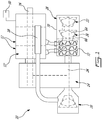
- the compound engine assembly 10 includes an engine core 12' with one or more internal combustion engine(s) 12.
- the core engine(s) 12 drive a common load.
- the common load includes an output shaft 16 which may be for example connected to a propeller through a reduction gearbox (not shown) and to which each core engine 12 is engaged.
- Other possible common loads may include, but are not limited to, one or more compressor and/or fan rotor(s), electrical generator(s), accessories, rotor mast(s), or any other type of load or combination thereof.
- the compound engine assembly 10 also includes a turbocharger including a compressor 20 and a second stage turbine 22 which are drivingly engaged; in the embodiment shown, they are interconnected by a common turbine shaft 24.
- the compressor 20 and the second stage turbine 22 may each be a single-stage device or a multiple-stage device with a single shaft or split on multiple independent shafts in parallel or in series, and may each be a centrifugal or axial device.
- the compressor 20 compresses the air before it is circulated to the core engine(s) 12 through an inlet manifold 18.
- the compressor 20 and the second stage turbine 22 may each include one or more rotors, with radial, axial or mixed flow blades.
- the turbine shaft 24 extends along a different axis than that of the output shaft 16, and parallel thereto; alternately, the turbine shaft 24 may extend transverse to the output shaft 16, or may be defined coaxially with the output shaft 16.
- the turbine shaft 24 and output shaft 16 are in driving engagement with one another, through a gearbox module 14 including any suitable type of transmission or gearbox, for example a planetary, star, offset or angular gear system.
- turbocharger may be omitted.
- Each core engine 12 provides an exhaust flow in the form of exhaust pulses.
- the exhaust flow from the core engines 12 is supplied to a compound or first stage turbine 26 in fluid communication therewith.
- the first stage turbine 26 could be an axial, radial or mixed flow turbine.
- the rotor blades 64 of the rotor of the first stage turbine 26 extend across an annular flow path 66.
- the rotor of the first stage turbine 26 is an axial rotor and the flow path 66 extends axially.
- the first stage turbine 26 is drivingly interconnected to the second stage turbine 22 by being mounted to the same turbine shaft 24, and accordingly also drivingly engaged to the output shaft 16 through the gearbox module 14.
- the turbines 26, 22 may rotate independently, with the first stage turbine 26 drivingly engaged to the output shaft 16, e.g. via the gearbox module 14, and the second stage turbine 22 drivingly engaged to the compressor 20.
- the outlet of the first stage turbine 26 is in fluid communication with an inlet of the second stage turbine 22. Energy is extracted from the exhaust gas exiting the first stage turbine 26 by the second stage turbine 22 to drive the compressor 20 via the connecting shaft 24. Both turbines form part of a turbine module 28, which will be further described below.
- the second stage turbine 22 is a pressure turbine, also known as a reaction turbine
- the first stage turbine 26 is configured as a velocity type turbine, also known as an impulse turbine.
- a pure impulse turbine works by changing the direction of the flow without accelerating the flow inside the rotor; the fluid is deflected without a significant pressure drop across the rotor blades.
- the blades of the pure impulse turbine are designed such that in a transverse plane perpendicular to the direction of flow, the area defined between the blades is the same at the leading edges of the blades and at the trailing edges of the blade: the flow area of the turbine is constant, and the blades are usually symmetrical about the plane of the rotating disc.
- the work of the pure impulse turbine is due only to the change of direction in the flow through the turbine blades.
- Typical pure impulse turbines include steam and hydraulic turbines.
- a reaction turbine accelerates the flow inside the rotor but needs a static pressure drop across the rotor to enable this flow acceleration.
- the blades of the reaction turbine are designed such that in a transverse plane perpendicular to the direction of flow, the area defined between the blades is larger at the leading edges of the blades than at the trailing edges of the blade: the flow area of the turbine reduces along the direction of flow, and the blades are usually not symmetrical about the plane of the rotating disc.
- the work of the pure reaction turbine is due mostly to the acceleration of the flow through the turbine blades.
- Aeronautical turbines referred to as impulse turbines typically have a reaction ratio of 0.25 (25% reaction) or lower, although other values are also possible.
- the first stage turbine 26 is configured to take benefit of the kinetic energy of the pulsating flow exiting the core engine(s) 12 while stabilizing the flow, and the second stage turbine 22 is configured to extract energy from the remaining pressure in the flow. Accordingly, the first stage turbine 26 has a lower (i.e. lower value) reaction ratio than that of the second stage turbine 22.
- the second stage turbine 22 has a reaction ratio higher than 0.25; in another particular embodiment, the second stage turbine 22 has a reaction ratio higher than 0.3; in another particular embodiment, the second stage turbine 22 has a reaction ratio of about 0.5; in another particular embodiment, the second stage turbine 22 has a reaction ratio higher than 0.5.
- the first stage turbine 26 has a reaction ratio of at most 0.2; in another particular embodiment, the first stage turbine 26 has a reaction ratio of at most 0.15; in another particular embodiment, the first stage turbine 26 has a reaction ratio of at most 0.1; in another particular embodiment, the first stage turbine 26 has a reaction ratio of at most 0.05.
- reaction ratios for the second stage turbine 22 can be combined with any of the above-mentioned reaction ratios for the first stage turbine 26 and that these ratios can be pressure-based or temperature-based. Other values are also possible.
- the air may optionally circulate through an intercooler between the compressor 20 and the core engine(s) 12, and the engine assembly 10 also includes a cooling system, including for example a circulation system for a coolant (e.g. water-ethylene, oil, air) to cool the housing of each core engine 12, an oil coolant for the internal mechanical parts of the core engine(s) 12, one or more coolant heat exchangers, etc.
- a coolant e.g. water-ethylene, oil, air
- each core engine 12 which in a particular embodiment are common rail fuel injectors, communicate with a source 30 of Heavy fuel (e.g. diesel, kerosene (jet fuel), equivalent biofuel), and deliver the heavy fuel into the core engine(s) 12 such that the combustion chamber is stratified with a rich fuel-air mixture near the ignition source and a leaner mixture elsewhere.
- Heavy fuel e.g. diesel, kerosene (jet fuel), equivalent biofuel
- each core engine 12 is a rotary internal combustion engine having a rotor sealingly engaged in a respective housing, for example a Wankel rotary engine.
- a Wankel rotary engine Referring to Fig. 2 , an exemplary embodiment of a Wankel engine is shown; it is understood that the configuration of the core engine(s) 12 used in the compound engine assembly 10, e.g. placement of ports, number and placement of seals, etc., may vary from that of the embodiment shown.
- each core engine 12 may be any other type of internal combustion engine including, but not limited to, any other type of rotary engine, and any other type of internal combustion engine (e.g. reciprocating engine).
- the engine core 12' includes a single Wankel engine, or four (4) Wankel engines, or any suitable number of internal combustion engines having any other suitable configuration (e.g. reciprocating engine).
- each Wankel engine comprises a housing 32 defining an internal cavity with a profile defining two lobes, which is preferably an epitrochoid.
- a rotor 34 is received within the internal cavity.
- the rotor defines three circumferentially-spaced apex portions 36, and a generally triangular profile with outwardly arched sides.
- the apex portions 36 are in sealing engagement with the inner surface of a peripheral wall 38 of the housing 32 to form three working chambers 40 between the rotor 34 and the housing 32.
- the rotor 34 is engaged to an eccentric portion 42 of the output shaft 16 to perform orbital revolutions within the internal cavity.
- the output shaft 16 performs three rotations for each orbital revolution of the rotor 34.
- the geometrical axis 44 of the rotor 34 is offset from and parallel to the axis 46 of the housing 32.
- each chamber 40 varies in volume and moves around the internal cavity to undergo the four phases of intake, compression, expansion and exhaust.
- the difference between the maximum and minimum volumes of each chamber 40 during the revolutions of the rotor 34 defines a displacement volume Vd of the engine.
- An intake port 48 is provided through the peripheral wall 38 for successively admitting compressed air from the inlet manifold 18 into each working chamber 40.
- An exhaust port 50 is also provided through the peripheral wall 38 for successively discharging the exhaust gases from each working chamber 40.
- Passages 52 for a glow plug, spark plug or other ignition element, as well as for one or more fuel injectors (not shown) are also provided through the peripheral wall 38.
- the intake port 48, the exhaust port 50 and/or the passages 52 may be provided through an end or side wall 54 of the housing; and/or, the ignition element and a pilot fuel injector may communicate with a pilot subchamber (not shown) defined in the housing 32 and communicating with the internal cavity for providing a pilot injection.
- the pilot subchamber may be for example defined in an insert (not shown) received in the peripheral wall 38.
- the working chambers 40 are sealed, for example by spring-loaded apex seals 56 extending from the rotor 34 to engage the peripheral wall 38, and spring-loaded face or gas seals 58 and end or corner seals 60 extending from the rotor 34 to engage the end walls 54.
- the rotor 34 also includes at least one spring-loaded oil seal ring 62 biased against the end wall 54 around the bearing for the rotor 34 on the shaft eccentric portion 42.
- Each Wankel engine provides an exhaust flow in the form of a relatively long exhaust pulse; for example, in a particular embodiment, each Wankel engine has one explosion per 360° of rotation of the output shaft, with the exhaust port remaining open for about 270° of that rotation.
- each Wankel engine has a volumetric expansion ratio of from 5 to 9, and a volumetric compression ratio lower than the volumetric expansion ratio.
- the power recovery of the first stage turbine 26 may be maximized by having the exhaust gas temperatures at the material limit, and as such is suitable for such relatively low volumetric compression ratios, which may help increase the power density of the Wankel engine and may also improve combustion at high speed and of heavy fuel.
- the turbine module 28 includes a turbine casing 70 containing the turbines 22, 26.
- the turbine casing 70 is annular, and may be monolithic or alternately made of two or more interconnected segments.
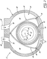
- the turbine module 28 further includes a support casing 72 rigidly connected to the turbine casing 70, through which the turbine casing 70 is connected to a remainder of the engine assembly 10, including the engine core 12'.
- the support casing 72 is rigidly connected to the gearbox module 14 (part of which is shown in Fig. 3 ), and the engine core 12' is also rigidly connected to the gearbox module 14 (see Fig. 1 ), for example to the engine housings.
- a load path is thus defined between the turbine casing 70 and the engine core 12' through the support casing 72 and gearbox module 14.
- Alternate configurations are also possible, including, but not limited to, the support casing 72 being directly rigidly connected to the engine core 12'.
- connection or “rigidly” as applied to a connection is intended to encompass any type of connection which allows a transfer of loads between the connected elements, including, but not limited to, reversible connections (e.g. fasteners) preventing or designed to prevent relative movement between the connected elements, and permanent connections (e.g. welding, brazing, monolithic assembly of elements, flanges clamped with a V-band coupling).
- reversible connections e.g. fasteners
- permanent connections e.g. welding, brazing, monolithic assembly of elements, flanges clamped with a V-band coupling.
- the support casing 72 directs the alignment of the static elements of the turbine module (e.g. scroll, vanes and housings) relative to the turbine shaft 24 and the rotating elements of the turbine module 28, the shaft 24 and rotating elements being supported via bearings 74, 74' and structure in the gearbox module 14.
- the support casing 72 thus also surrounds a part of the gearbox module 14 encasing the turbine shaft 24, including the rear shaft bearings 74', oil feed system and scavenge cavities and tubes 76, and carbon seals 78.
- a dotted line illustrates the separation between the elements forming part of the turbine module 28 (right) and the elements forming part of the gearbox module 14 (left).
- the turbine module 28 is thus free of oil system features, which in a particular embodiment facilitates removal of the turbine module 28 from the engine assembly 10.
- the support casing 72 forms the only rigid connection between the turbine casing 70 and the remainder of the engine assembly 10.
- the support casing 72 is annular is configured as a split casing, with two interconnected sections 72a, 72b each extending approximately around half of the complete circumference of the support casing 72.
- Such a configuration may facilitate assembly of the support casing 72 and of the elements received therein.
- Alternate configurations are also possible, for example including more than two sections each extending around their respective portion of the circumference.
- a significant portion of the support casing 72 is formed by a plurality of interconnecting ribs 84, with through openings 86 being defined between adjacent ones of the ribs 84 and between the ribs 84 and adjacent structure of the support casing 72.
- triangular openings 86 are shown, it is understood that any other appropriate shape can alternately be used.
- Part of the support casing 72 thus has a cage-like configuration, with the openings 86 enabling ventilation of the elements contained in the support casing 72.
- the openings 86 allow ventilation of the bearing housings, seals, and/or any other element requiring ventilation and located in the portion of the gearbox module 14 received in the support casing 72.
- a smaller or greater portion (e.g. the entirety) of the support casing 72 may have the openings 86 defined therethrough, for example depending on the cooling requirements of the elements contained in the support casing 72.
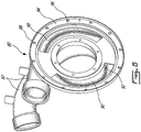
- the turbine module 28 further includes an inlet scroll 80 connected to the upstream end of the turbine casing 70 (e.g. rigidly connected thereto).
- the inlet scroll 80 is at least partially contained in the support casing 72, but does not have any direct rigid connection therewith, such as to be movable with respect thereto. In a particular embodiment, no direct connection is provided between the inlet scroll 80 and support casing 72; alternately, the two may be directly interconnected by a floating connection, i.e. a connection allowing relative movement therebetween.
- the openings 86 of the support casing 72 enable ventilation of the inlet scroll 80 received therein.
- the inlet scroll 80 includes an inlet pipe 82 for each exhaust port 50 of the engine core 12'.
- Each inlet pipe 82 is in fluid communication with an inlet of the first stage turbine 26, i.e. with the flow path 66 (see Figs. 1 and 4 ) of the first stage turbine 26, upstream of its rotor blades 64.
- a respective exhaust pipe 68 provides a fluid connection between each exhaust port 50 of the engine core 12' and the respective inlet pipe 82.
- the inlet scroll 80 includes an annular duct 88.
- Each inlet pipe 82 extends around part of a circumference of the duct 88, and communicates with a respective internal cavity 90 through a respective inlet port 92, with the inlet ports 92 and internal cavities 90 being circumferentially spaced apart.
- the inlet scroll 80 includes a flange 94 at its downstream end, for attachment to the turbine casing 70, for example through a circumferential array of fasteners received through corresponding holes 96 in the flange 94 and in a corresponding flange of the turbine casing 70. When attached to the turbine casing 70, the internal cavities 90 communicate with the flow path 66 of the first stage turbine 26.
- the inlet scroll 80 is monolithic.
- the internal cross-sectional area of the conduit directing the exhaust flow in each exhaust pipe 68 and inlet pipe 82 is constant, and this constant internal cross-sectional area corresponds to that of the engine exhaust port 50 connected to the exhaust pipe 68.
- the exhaust pipe 68 and/or inlet pipe 82 may have a non-constant internal cross-sectional area, and/or a different internal cross-sectional area than that of the exhaust port 50 (for example smaller than that of the corresponding exhaust port 50).
- the exhaust pipe(s) 68, inlet pipe(s) 82 and remainder of the inlet scroll 80 are shaped to direct the exhaust pulses onto the blades 64 of the first stage turbine 26 to allow the exhaust pulses to drive rotation of the rotor of the first stage turbine 26.
- the exhaust pipes 68 extend independently from one another, and have a relatively small length, which in a particular embodiment allows to minimize the distance between the exhaust port 50 and turbine 26 to minimize pressure losses of the exhaust pulses, and accordingly maximize the turbine's extraction of energy form the exhaust pulses.
- Each exhaust pipe 68 has a first end sealingly engaged to the exhaust port 50 with a first connection 68a and a second end sealingly engaged to the inlet pipe 82 with a second connection 68b.
- the exhaust pipe 68 is movable about at least one of the connections 68a, 68b; in a particular embodiment, such movement prevent loads being transmitted between the engine core 12' and the inlet scroll 80 through the exhaust pipes 68, for example upon thermal expansion of the inlet scroll 80, exhaust pipes 68, engine core 12 and/or turbine module 28.
- One or both end(s) of the exhaust pipe 68 can thus move with respect to the exhaust port 50 or inlet pipe 82 it is connected thereto, while maintaining a seal at the connection against loss of exhaust flow therearound.
- the exhaust pipe 68 is movable about both connections 68a, 68b.
- Each end of the exhaust pipe 68 includes a spherical bearing surface 98, defined as an annular surface extending around the end and having a semicircular cross-section.
- the spherical bearing surface 98 of each end is in sliding engagement with a cylindrical bearing surface 100 of the respective exhaust port 50 or inlet pipe 82 to form the connections 68a, 68b.
- Each connection 68a, 68b thus allows the exhaust pipe 68 to pivot around multiple axes extending transversely to the central axis C E of the exhaust pipe 68; the possible range of motion thus allows to change the angle between the central axis C E of the exhaust pipe 68 and the central axis C I of the inlet pipe 82 adjacent its connection 68b with the exhaust pipe 68, as well as the angle between the central axis C E of the exhaust pipe 68 and the central axis C P of the exhaust port 50 adjacent its connection 68a with the exhaust pipe 68.
- An example of possible relative movement is illustrated in a moved position shown in dotted lines in Fig. 7 , where a shift in the position of the inlet pipe 82 with respect to that of the exhaust port 50 is compensated by a pivoting motion of the exhaust pipe 68.
- one of the connected inlet and exhaust pipes 82, 68 extends through a respective opening 86' defined in the support casing 72.
- the inlet or exhaust pipe 82, 68 floatingly extends through the respective opening 86', i.e., is free to move within the opening.
- the inlet and exhaust pipes 82, 68 are thus connected by extending through opening of the support casing 72, without contacting the support casing 72 and without any direct connection therewith.
- a floating connection avoiding load transfer to the inlet and exhaust pipes 82, 68 may be provided.
- the inlet pipes 82 extend through the opening 86' of the support casing 72, so that the connection 68b between each inlet pipe 82 and its respective exhaust pipe 68 is located outside of the support casing 72; the inlet pipes 82 extend through the openings 86' generally circumferentially, i.e. at a non-zero angle with respect to the rotational axis R of the turbine rotors, and spiral inward toward the turbine flow path.
- Other configurations are also possible.
- the exhaust pipes 68 may penetrate the support casing 72 through the corresponding openings 86' so that the connection 68b between each inlet pipe 82 and exhaust pipe 68 is located inside the support casing 72; the openings 86' of the support casing 72 and/or the connection 68b between the inlet and exhaust pipes 82, 68 are configured to prevent contact between the exhaust pipe 68 and support casing 72.
- the load path between the turbine casing 70 and the engine core 12' is thus defined by rigidly connecting the turbine casing 70 to the gearbox module with at least the support casing 72, and circulating the exhaust gas from each exhaust port 50 to the inlet scroll 80 through the pipes 68, 82 which extend through the support casing 72 without contacting it.
- the inlet scroll 80 is excluded from the load path by avoiding direct connection of the inlet scroll 80 to the support casing 72 and by allowing relative movement between each exhaust pipe 68 and one or both of the exhaust port 50 and the inlet scroll 80.
- the load path can thus be defined independently of the inlet scroll 80 and exhaust pipes 68 which undergo significant thermal expansion during use, which in a particular embodiment allows for reduction or minimization of the loads on the assembly 10 which could be induced by such thermal expansion.
- the exhaust pipe(s) 68, inlet scroll 80 and support casing 72 may be used between an engine core and one or more turbine(s) not compounded with the engine core.
- the inlet scroll 80 may be configured to deliver exhaust gases to a radial turbine.
Claims (13)
- Motoranordnung (10), umfassend:einen Motorkern (12'), der einen Verbrennungsmotor (12) beinhaltet, der einen Auslassanschluss (50) aufweist;ein Turbinenmodul (28), beinhaltend ein Turbinengehäuse (70), das eine Turbine (22, 26) enthält, ein Stützgehäuse (72), das das Turbinengehäuse (70) steif mit zumindest dem Motorkern (12') verbindet, und eine Einlassspirale (80), die mit dem Turbinengehäuse (70) verbunden ist, wobei die Einlassspirale (80) ein Einlassrohr (82) in Fluidkommunikation mit einem Einlass der Turbine (22, 26) beinhaltet; undein Auslassrohr (68), das mit dem Auslassanschluss (50) und dem Einlassrohr (82) verbunden ist und Fluidkommunikation dazwischen bereitstellt;wobei die Einlassspirale (80) ohne direkte steife Verbindung mit dem Stützgehäuse (72) mit dem Turbinengehäuse (70) verbunden ist; unddas Auslassrohr (68) relativ zu zumindest einem von dem Auslassanschluss (50) und dem Einlassrohr (82) an einer entsprechenden Verbindung (68a, 68b) damit bewegbar ist;dadurch gekennzeichnet, dass:
sich eines von dem Auslass- und Einlassrohr (68, 82) schwebend durch eine entsprechende Öffnung (86') erstreckt, die in dem Stützgehäuse (72) definiert ist, sodass sich eines von dem Auslass- und Einlassrohr (68, 82) frei innerhalb der entsprechenden Öffnung (86') bewegen kann. - Motoranordnung nach Anspruch 1, wobei sich das eine von dem Auslass- und Einlassrohr (68, 82) in einem Winkel ungleich Null in Bezug auf eine Drehachse (R) der Turbine (22, 26) durch die entsprechende Öffnung (86') erstreckt.
- Motoranordnung nach Anspruch 1 oder 2, wobei sich das Einlassrohr (82) durch die entsprechende Öffnung (86') erstreckt, wobei das Einlass- und Auslassrohr (68, 82) außerhalb des Stützgehäuses (72) verbunden sind.
- Motoranordnung nach einem der vorhergehenden Ansprüche, wobei das Auslassrohr (68) relativ zu jedem von dem Auslassanschluss (50) und dem Einlassrohr (82) um die entsprechende Verbindung (68a, 68b) herum bewegbar ist.
- Motoranordnung nach Anspruch 4, wobei ein erstes und zweites Ende des Auslassrohres (68) kugelförmige Lagerflächen (98) in Gleiteingriff mit Flächen des Auslassanschlusses (50) und des Einlassrohres (82) beinhalten, um eine erste und zweite Verbindung (68a, 68b) zu bilden, wobei das Auslassrohr (68) um jede von der ersten und zweiten Verbindung (68a, 68b) schwenkbar ist, um einen Winkel zwischen einer zentralen Achse (CE) des Auslassrohres (68) und zentralen Achsen (CP, CI) des jeweiligen Auslassanschlusses (50) und Einlassrohres (82) zu ändern.
- Motoranordnung nach einem der vorhergehenden Ansprüche, wobei das Stützgehäuse (72) das Turbinengehäuse (70) steif mit einem Getriebekastenmodul (14) verbindet, das steif mit dem Motorkern (12') verbunden ist, wobei das Getriebekastenmodul (14) eine drehbare Welle (16) des Verbrennungsmotors (12) zu einer drehbaren Welle (24) der Turbine (22, 26) in Antriebseingriff nimmt.
- Motoranordnung nach einem der vorhergehenden Ansprüche, wobei die Einlassspirale (80) einen ringförmigen Kanal (88) beinhaltet, der einen jeweiligen Innenhohlraum (90) definiert, der die Fluidkommunikation zwischen dem Einlassrohr (82) und dem Einlass der Turbine (22, 26) bereitstellt.
- Motoranordnung nach einem der vorhergehenden Ansprüche, wobei das Stützgehäuse (72) ringförmig ist und zumindest zwei miteinander verbundene Abschnitte (72a, 72b) beinhaltet, wobei sich jeder Abschnitt (72a, 72b) um nur einen Teil eines vollständigen Umfangs des ringförmigen Stützgehäuses (72) erstreckt.
- Motoranordnung nach einem der vorhergehenden Ansprüche, wobei zumindest ein Abschnitt des Stützgehäuses (72) durch eine Vielzahl von miteinander verbundenen Rippen (84) mit Durchgangsöffnungen (86, 86'), die zwischen benachbarten der Rippen (84) definiert sind, gebildet ist.
- Motoranordnung nach einem der vorhergehenden Ansprüche, wobei der Verbrennungsmotor (12) einen Rotor (34) beinhaltet, der dichtend und drehbar innerhalb eines Innenhohlraums aufgenommen ist, um sich drehende Kammern (40) mit variablem Volumen in dem Innenhohlraum bereitzustellen, wobei der Rotor (34) drei Spitzenabschnitte (36) aufweist, die die sich drehenden Kammern (40) trennen und für exzentrische Umdrehungen innerhalb des Innenhohlraums angebracht sind, wobei der Innenhohlraum eine Epitrochoidenform mit zwei Lappen aufweist.
- Motoranordnung nach einem der vorhergehenden Ansprüche, wobei:der Motorkern (12') zumindest einen Verbrennungsmotor (12) in Antriebseingriff mit einer Ausgangswelle (16) beinhaltet, wobei jeder Verbrennungsmotor (12) einen Rotor (34) beinhaltet, der dichtend und drehbar innerhalb eines Innenhohlraums aufgenommen ist, um sich drehende Kammern mit variablem Volumen (20) in dem Innenhohlraum bereitzustellen, wobei jeder Verbrennungsmotor (12) einen Auslassanschluss (50) in Fluidkommunikation mit dem Innenhohlraum davon beinhaltet;die Turbine (22, 26) eine Turbinenwelle (24) in Antriebseingriff mit der Ausgangswelle (16) durch ein Getriebekastenmodul (14) aufweist, wobei das Stützgehäuse (72) das Turbinengehäuse (70) steif mit dem Getriebekastenmodul (14) verbindet, wobei sich die Turbinenwelle (24) innerhalb des Stützgehäuses (72) erstreckt und die Einlassspirale (80) ein jeweiliges Einlassrohr (82) für jeden Auslassanschluss (50) beinhaltet, wobei jedes Einlassrohr (82) in Fluidkommunikation mit dem Einlass der Turbine (22, 26) ist;ein Auslassrohr (68) für jeden Auslassanschluss (50) bereitgestellt ist, wobei jedes Auslassrohr (68) mit dem jeweiligen Auslassanschluss (50) und dem jeweiligen Einlassrohr (82) verbunden ist und Fluidkommunikation dazwischen bereitstellt, wobei jedes Auslassrohr (68) relativ zu zumindest einem von dem jeweiligen Auslassanschluss (50) und dem jeweiligen Einlassrohr (82) an einer entsprechenden Verbindung (68a, 68b) damit bewegbar ist;wobei sich eines von jedem verbundenen Auslass- und Einlassrohr (68, 82) durch eine entsprechende Öffnung (86'), die durch das Stützgehäuse (72) definiert ist, ohne eine direkte steife Verbindung mit dem Stützgehäuse (72) erstreckt.
- Motoranordnung nach Anspruch 11, wobei die Turbine (22, 26) ein druckbasiertes Reaktionsverhältnis von höchstens 0,25 aufweist.
- Motoranordnung nach Anspruch 11 oder 12, wobei die Turbine eine erste Turbine (26) ist, wobei das Turbinengehäuse (70) auch eine zweite Turbine (22) enthält, die einen Einlass in Fluidkommunikation mit einem Auslass der ersten Turbine (26) aufweist, wobei die zweite Turbine (22) ein Reaktionsverhältnis aufweist, das größer als dasjenige der ersten Turbine (26) ist.
Priority Applications (1)
| Application Number | Priority Date | Filing Date | Title |
|---|---|---|---|
| PL17153701T PL3199767T3 (pl) | 2016-01-29 | 2017-01-30 | Zespół silnika z obudową nośną turbiny |
Applications Claiming Priority (1)
| Application Number | Priority Date | Filing Date | Title |
|---|---|---|---|
| US15/010,933 US9970295B2 (en) | 2016-01-29 | 2016-01-29 | Engine assembly with turbine support casing |
Publications (2)
| Publication Number | Publication Date |
|---|---|
| EP3199767A1 EP3199767A1 (de) | 2017-08-02 |
| EP3199767B1 true EP3199767B1 (de) | 2019-03-27 |
Family
ID=57914884
Family Applications (1)
| Application Number | Title | Priority Date | Filing Date |
|---|---|---|---|
| EP17153701.2A Active EP3199767B1 (de) | 2016-01-29 | 2017-01-30 | Motoranordnung mit turbinenstützgehäuse |
Country Status (5)
| Country | Link |
|---|---|
| US (1) | US9970295B2 (de) |
| EP (1) | EP3199767B1 (de) |
| CA (1) | CA2956593A1 (de) |
| ES (1) | ES2727198T3 (de) |
| PL (1) | PL3199767T3 (de) |
Families Citing this family (5)
| Publication number | Priority date | Publication date | Assignee | Title |
|---|---|---|---|---|
| US10227889B2 (en) * | 2015-02-05 | 2019-03-12 | Garrett Transportation I Inc. | Variable geometry nozzle for partitioned volute |
| US10533492B2 (en) | 2015-02-20 | 2020-01-14 | Pratt & Whitney Canada Corp. | Compound engine assembly with mount cage |
| US10533500B2 (en) | 2015-02-20 | 2020-01-14 | Pratt & Whitney Canada Corp. | Compound engine assembly with mount cage |
| US10823289B2 (en) * | 2017-11-17 | 2020-11-03 | Bell Helicopter Textron Inc. | Floating ducts |
| EP3539865A1 (de) * | 2018-03-12 | 2019-09-18 | Ge Avio S.r.l. | Lüfterschaufelstützanordnung |
Citations (1)
| Publication number | Priority date | Publication date | Assignee | Title |
|---|---|---|---|---|
| US20130047605A1 (en) * | 2011-08-30 | 2013-02-28 | GM Global Technology Operations LLC | Turbocharger |
Family Cites Families (14)
| Publication number | Priority date | Publication date | Assignee | Title |
|---|---|---|---|---|
| DE3217633C2 (de) | 1982-05-11 | 1984-09-06 | Dr.Ing.H.C. F. Porsche Ag, 7000 Stuttgart | Verbindungsleitung zwischen Verdichter und Saugrohr einer Brennkraftmaschine |
| US4964275A (en) | 1987-12-14 | 1990-10-23 | Paul Marius A | Multicylinder compound engine |
| DE3908286C1 (de) | 1989-03-14 | 1990-02-22 | Daimler-Benz Aktiengesellschaft, 7000 Stuttgart, De | |
| JPH0874570A (ja) | 1994-08-31 | 1996-03-19 | Aisin Takaoka Ltd | 排気マニホルドとターボ過給機との連結構造 |
| US5639222A (en) | 1995-07-06 | 1997-06-17 | Wagner Spray Tech Corporation | Close coupled series turbine mounting |
| GB2446146B (en) | 2007-01-31 | 2009-11-18 | Gm Global Tech Operations Inc | Arrangement of a two stage turbocharger system for an internal combustion engine |
| US8266906B2 (en) | 2009-03-11 | 2012-09-18 | GM Global Technology Operations LLC | Asymmetric split-inlet turbine housing |
| WO2011031595A2 (en) | 2009-09-10 | 2011-03-17 | Borgwarner Inc. | Exhaust-gas supply device of a turbine wheel of an exhaust-gas turbocharger |
| AT509691B1 (de) | 2010-03-18 | 2013-09-15 | Avl List Gmbh | Brennkraftmaschine mit einer verbindungsanordnung für einen zylinderkopf |
| US8443602B2 (en) | 2010-03-30 | 2013-05-21 | GM Global Technology Operations LLC | Closely-coupled exhaust aftertreatment device for a turbocharged internal combustion engine |
| EP2655829B1 (de) | 2010-12-22 | 2015-04-01 | Honeywell International Inc. | Zylinderkopf und turboladeranordnung |
| CN104040141B (zh) | 2012-01-17 | 2016-08-24 | 博格华纳公司 | 排气涡轮增压器 |
| US9194232B2 (en) * | 2012-07-20 | 2015-11-24 | Pratt & Whitney Canada Corp. | Compound cycle engine |
| US9926843B2 (en) | 2012-07-20 | 2018-03-27 | Pratt & Whitney Canada Corp. | Compound cycle engine |
-
2016
- 2016-01-29 US US15/010,933 patent/US9970295B2/en active Active
-
2017
- 2017-01-27 CA CA2956593A patent/CA2956593A1/en active Pending
- 2017-01-30 ES ES17153701T patent/ES2727198T3/es active Active
- 2017-01-30 PL PL17153701T patent/PL3199767T3/pl unknown
- 2017-01-30 EP EP17153701.2A patent/EP3199767B1/de active Active
Patent Citations (1)
| Publication number | Priority date | Publication date | Assignee | Title |
|---|---|---|---|---|
| US20130047605A1 (en) * | 2011-08-30 | 2013-02-28 | GM Global Technology Operations LLC | Turbocharger |
Also Published As
| Publication number | Publication date |
|---|---|
| EP3199767A1 (de) | 2017-08-02 |
| US9970295B2 (en) | 2018-05-15 |
| PL3199767T3 (pl) | 2019-09-30 |
| ES2727198T3 (es) | 2019-10-14 |
| CA2956593A1 (en) | 2017-07-29 |
| US20170218760A1 (en) | 2017-08-03 |
Similar Documents
| Publication | Publication Date | Title |
|---|---|---|
| US10968824B2 (en) | Compound cycle engine | |
| US9926843B2 (en) | Compound cycle engine | |
| EP2687675B1 (de) | Zusammengesetzter Zyklusmotor | |
| EP2687676B1 (de) | Zusammengesetzter Zyklusmotor | |
| EP3199767B1 (de) | Motoranordnung mit turbinenstützgehäuse | |
| CA2933112C (en) | Compound cycle engine | |
| EP3199754B1 (de) | Einlassleitschaufelgruppe | |
| US10393014B2 (en) | Engine assembly with exhaust pipe nozzle | |
| EP3348821B1 (de) | Mantelstrom-triebwerksanordnung mit zwischenkühler | |
| EP3106644B1 (de) | Zusammengesetzter zyklusmotor |
Legal Events
| Date | Code | Title | Description |
|---|---|---|---|
| PUAI | Public reference made under article 153(3) epc to a published international application that has entered the european phase |
Free format text: ORIGINAL CODE: 0009012 |
|
| STAA | Information on the status of an ep patent application or granted ep patent |
Free format text: STATUS: THE APPLICATION HAS BEEN PUBLISHED |
|
| AK | Designated contracting states |
Kind code of ref document: A1 Designated state(s): AL AT BE BG CH CY CZ DE DK EE ES FI FR GB GR HR HU IE IS IT LI LT LU LV MC MK MT NL NO PL PT RO RS SE SI SK SM TR |
|
| AX | Request for extension of the european patent |
Extension state: BA ME |
|
| STAA | Information on the status of an ep patent application or granted ep patent |
Free format text: STATUS: REQUEST FOR EXAMINATION WAS MADE |
|
| 17P | Request for examination filed |
Effective date: 20180202 |
|
| RBV | Designated contracting states (corrected) |
Designated state(s): AL AT BE BG CH CY CZ DE DK EE ES FI FR GB GR HR HU IE IS IT LI LT LU LV MC MK MT NL NO PL PT RO RS SE SI SK SM TR |
|
| STAA | Information on the status of an ep patent application or granted ep patent |
Free format text: STATUS: EXAMINATION IS IN PROGRESS |
|
| 17Q | First examination report despatched |
Effective date: 20180409 |
|
| GRAP | Despatch of communication of intention to grant a patent |
Free format text: ORIGINAL CODE: EPIDOSNIGR1 |
|
| STAA | Information on the status of an ep patent application or granted ep patent |
Free format text: STATUS: GRANT OF PATENT IS INTENDED |
|
| INTG | Intention to grant announced |
Effective date: 20181004 |
|
| RIN1 | Information on inventor provided before grant (corrected) |
Inventor name: VILLENEUVE, BRUNO Inventor name: BOLDUC, SEBASTIEN Inventor name: FONTAINE, MIKE |
|
| GRAS | Grant fee paid |
Free format text: ORIGINAL CODE: EPIDOSNIGR3 |
|
| GRAA | (expected) grant |
Free format text: ORIGINAL CODE: 0009210 |
|
| STAA | Information on the status of an ep patent application or granted ep patent |
Free format text: STATUS: THE PATENT HAS BEEN GRANTED |
|
| AK | Designated contracting states |
Kind code of ref document: B1 Designated state(s): AL AT BE BG CH CY CZ DE DK EE ES FI FR GB GR HR HU IE IS IT LI LT LU LV MC MK MT NL NO PL PT RO RS SE SI SK SM TR |
|
| REG | Reference to a national code |
Ref country code: GB Ref legal event code: FG4D |
|
| REG | Reference to a national code |
Ref country code: CH Ref legal event code: EP |
|
| REG | Reference to a national code |
Ref country code: AT Ref legal event code: REF Ref document number: 1113330 Country of ref document: AT Kind code of ref document: T Effective date: 20190415 |
|
| REG | Reference to a national code |
Ref country code: IE Ref legal event code: FG4D |
|
| REG | Reference to a national code |
Ref country code: DE Ref legal event code: R096 Ref document number: 602017002858 Country of ref document: DE |
|
| REG | Reference to a national code |
Ref country code: CH Ref legal event code: NV Representative=s name: VALIPAT S.A. C/O BOVARD SA NEUCHATEL, CH |
|
| PG25 | Lapsed in a contracting state [announced via postgrant information from national office to epo] |
Ref country code: SE Free format text: LAPSE BECAUSE OF FAILURE TO SUBMIT A TRANSLATION OF THE DESCRIPTION OR TO PAY THE FEE WITHIN THE PRESCRIBED TIME-LIMIT Effective date: 20190327 Ref country code: FI Free format text: LAPSE BECAUSE OF FAILURE TO SUBMIT A TRANSLATION OF THE DESCRIPTION OR TO PAY THE FEE WITHIN THE PRESCRIBED TIME-LIMIT Effective date: 20190327 Ref country code: NO Free format text: LAPSE BECAUSE OF FAILURE TO SUBMIT A TRANSLATION OF THE DESCRIPTION OR TO PAY THE FEE WITHIN THE PRESCRIBED TIME-LIMIT Effective date: 20190627 Ref country code: LT Free format text: LAPSE BECAUSE OF FAILURE TO SUBMIT A TRANSLATION OF THE DESCRIPTION OR TO PAY THE FEE WITHIN THE PRESCRIBED TIME-LIMIT Effective date: 20190327 |
|
| REG | Reference to a national code |
Ref country code: NL Ref legal event code: MP Effective date: 20190327 |
|
| PG25 | Lapsed in a contracting state [announced via postgrant information from national office to epo] |
Ref country code: GR Free format text: LAPSE BECAUSE OF FAILURE TO SUBMIT A TRANSLATION OF THE DESCRIPTION OR TO PAY THE FEE WITHIN THE PRESCRIBED TIME-LIMIT Effective date: 20190628 Ref country code: LV Free format text: LAPSE BECAUSE OF FAILURE TO SUBMIT A TRANSLATION OF THE DESCRIPTION OR TO PAY THE FEE WITHIN THE PRESCRIBED TIME-LIMIT Effective date: 20190327 Ref country code: NL Free format text: LAPSE BECAUSE OF FAILURE TO SUBMIT A TRANSLATION OF THE DESCRIPTION OR TO PAY THE FEE WITHIN THE PRESCRIBED TIME-LIMIT Effective date: 20190327 Ref country code: HR Free format text: LAPSE BECAUSE OF FAILURE TO SUBMIT A TRANSLATION OF THE DESCRIPTION OR TO PAY THE FEE WITHIN THE PRESCRIBED TIME-LIMIT Effective date: 20190327 Ref country code: RS Free format text: LAPSE BECAUSE OF FAILURE TO SUBMIT A TRANSLATION OF THE DESCRIPTION OR TO PAY THE FEE WITHIN THE PRESCRIBED TIME-LIMIT Effective date: 20190327 Ref country code: BG Free format text: LAPSE BECAUSE OF FAILURE TO SUBMIT A TRANSLATION OF THE DESCRIPTION OR TO PAY THE FEE WITHIN THE PRESCRIBED TIME-LIMIT Effective date: 20190627 |
|
| REG | Reference to a national code |
Ref country code: ES Ref legal event code: FG2A Ref document number: 2727198 Country of ref document: ES Kind code of ref document: T3 Effective date: 20191014 |
|
| PG25 | Lapsed in a contracting state [announced via postgrant information from national office to epo] |
Ref country code: RO Free format text: LAPSE BECAUSE OF FAILURE TO SUBMIT A TRANSLATION OF THE DESCRIPTION OR TO PAY THE FEE WITHIN THE PRESCRIBED TIME-LIMIT Effective date: 20190327 Ref country code: EE Free format text: LAPSE BECAUSE OF FAILURE TO SUBMIT A TRANSLATION OF THE DESCRIPTION OR TO PAY THE FEE WITHIN THE PRESCRIBED TIME-LIMIT Effective date: 20190327 Ref country code: PT Free format text: LAPSE BECAUSE OF FAILURE TO SUBMIT A TRANSLATION OF THE DESCRIPTION OR TO PAY THE FEE WITHIN THE PRESCRIBED TIME-LIMIT Effective date: 20190727 Ref country code: AL Free format text: LAPSE BECAUSE OF FAILURE TO SUBMIT A TRANSLATION OF THE DESCRIPTION OR TO PAY THE FEE WITHIN THE PRESCRIBED TIME-LIMIT Effective date: 20190327 Ref country code: SK Free format text: LAPSE BECAUSE OF FAILURE TO SUBMIT A TRANSLATION OF THE DESCRIPTION OR TO PAY THE FEE WITHIN THE PRESCRIBED TIME-LIMIT Effective date: 20190327 |
|
| PG25 | Lapsed in a contracting state [announced via postgrant information from national office to epo] |
Ref country code: SM Free format text: LAPSE BECAUSE OF FAILURE TO SUBMIT A TRANSLATION OF THE DESCRIPTION OR TO PAY THE FEE WITHIN THE PRESCRIBED TIME-LIMIT Effective date: 20190327 |
|
| PG25 | Lapsed in a contracting state [announced via postgrant information from national office to epo] |
Ref country code: IS Free format text: LAPSE BECAUSE OF FAILURE TO SUBMIT A TRANSLATION OF THE DESCRIPTION OR TO PAY THE FEE WITHIN THE PRESCRIBED TIME-LIMIT Effective date: 20190727 |
|
| REG | Reference to a national code |
Ref country code: DE Ref legal event code: R097 Ref document number: 602017002858 Country of ref document: DE |
|
| PG25 | Lapsed in a contracting state [announced via postgrant information from national office to epo] |
Ref country code: DK Free format text: LAPSE BECAUSE OF FAILURE TO SUBMIT A TRANSLATION OF THE DESCRIPTION OR TO PAY THE FEE WITHIN THE PRESCRIBED TIME-LIMIT Effective date: 20190327 |
|
| PLBE | No opposition filed within time limit |
Free format text: ORIGINAL CODE: 0009261 |
|
| STAA | Information on the status of an ep patent application or granted ep patent |
Free format text: STATUS: NO OPPOSITION FILED WITHIN TIME LIMIT |
|
| PG25 | Lapsed in a contracting state [announced via postgrant information from national office to epo] |
Ref country code: SI Free format text: LAPSE BECAUSE OF FAILURE TO SUBMIT A TRANSLATION OF THE DESCRIPTION OR TO PAY THE FEE WITHIN THE PRESCRIBED TIME-LIMIT Effective date: 20190327 |
|
| 26N | No opposition filed |
Effective date: 20200103 |
|
| PG25 | Lapsed in a contracting state [announced via postgrant information from national office to epo] |
Ref country code: TR Free format text: LAPSE BECAUSE OF FAILURE TO SUBMIT A TRANSLATION OF THE DESCRIPTION OR TO PAY THE FEE WITHIN THE PRESCRIBED TIME-LIMIT Effective date: 20190327 |
|
| PG25 | Lapsed in a contracting state [announced via postgrant information from national office to epo] |
Ref country code: MC Free format text: LAPSE BECAUSE OF FAILURE TO SUBMIT A TRANSLATION OF THE DESCRIPTION OR TO PAY THE FEE WITHIN THE PRESCRIBED TIME-LIMIT Effective date: 20190327 |
|
| REG | Reference to a national code |
Ref country code: BE Ref legal event code: MM Effective date: 20200131 |
|
| PG25 | Lapsed in a contracting state [announced via postgrant information from national office to epo] |
Ref country code: LU Free format text: LAPSE BECAUSE OF NON-PAYMENT OF DUE FEES Effective date: 20200130 |
|
| PG25 | Lapsed in a contracting state [announced via postgrant information from national office to epo] |
Ref country code: BE Free format text: LAPSE BECAUSE OF NON-PAYMENT OF DUE FEES Effective date: 20200131 |
|
| PG25 | Lapsed in a contracting state [announced via postgrant information from national office to epo] |
Ref country code: IE Free format text: LAPSE BECAUSE OF NON-PAYMENT OF DUE FEES Effective date: 20200130 |
|
| REG | Reference to a national code |
Ref country code: AT Ref legal event code: UEP Ref document number: 1113330 Country of ref document: AT Kind code of ref document: T Effective date: 20190327 |
|
| PG25 | Lapsed in a contracting state [announced via postgrant information from national office to epo] |
Ref country code: MT Free format text: LAPSE BECAUSE OF FAILURE TO SUBMIT A TRANSLATION OF THE DESCRIPTION OR TO PAY THE FEE WITHIN THE PRESCRIBED TIME-LIMIT Effective date: 20190327 Ref country code: CY Free format text: LAPSE BECAUSE OF FAILURE TO SUBMIT A TRANSLATION OF THE DESCRIPTION OR TO PAY THE FEE WITHIN THE PRESCRIBED TIME-LIMIT Effective date: 20190327 |
|
| PG25 | Lapsed in a contracting state [announced via postgrant information from national office to epo] |
Ref country code: MK Free format text: LAPSE BECAUSE OF FAILURE TO SUBMIT A TRANSLATION OF THE DESCRIPTION OR TO PAY THE FEE WITHIN THE PRESCRIBED TIME-LIMIT Effective date: 20190327 |
|
| PGFP | Annual fee paid to national office [announced via postgrant information from national office to epo] |
Ref country code: PL Payment date: 20221222 Year of fee payment: 7 |
|
| PGFP | Annual fee paid to national office [announced via postgrant information from national office to epo] |
Ref country code: ES Payment date: 20230201 Year of fee payment: 7 Ref country code: CH Payment date: 20230201 Year of fee payment: 7 Ref country code: AT Payment date: 20221222 Year of fee payment: 7 |
|
| PGFP | Annual fee paid to national office [announced via postgrant information from national office to epo] |
Ref country code: IT Payment date: 20230103 Year of fee payment: 7 Ref country code: DE Payment date: 20221220 Year of fee payment: 7 |
|
| P01 | Opt-out of the competence of the unified patent court (upc) registered |
Effective date: 20230530 |
|
| PGFP | Annual fee paid to national office [announced via postgrant information from national office to epo] |
Ref country code: GB Payment date: 20231219 Year of fee payment: 8 |
|
| PGFP | Annual fee paid to national office [announced via postgrant information from national office to epo] |
Ref country code: FR Payment date: 20231219 Year of fee payment: 8 Ref country code: CZ Payment date: 20231227 Year of fee payment: 8 |
|
| PGFP | Annual fee paid to national office [announced via postgrant information from national office to epo] |
Ref country code: PL Payment date: 20231221 Year of fee payment: 8 |
|
| PGFP | Annual fee paid to national office [announced via postgrant information from national office to epo] |
Ref country code: ES Payment date: 20240202 Year of fee payment: 8 |
|
| PGFP | Annual fee paid to national office [announced via postgrant information from national office to epo] |
Ref country code: AT Payment date: 20231222 Year of fee payment: 8 |