EP3199765A1 - Rails de fixation d'aube de turbine permettant de réduire la contrainte sur le congé de raccordement - Google Patents
Rails de fixation d'aube de turbine permettant de réduire la contrainte sur le congé de raccordement Download PDFInfo
- Publication number
- EP3199765A1 EP3199765A1 EP17153625.3A EP17153625A EP3199765A1 EP 3199765 A1 EP3199765 A1 EP 3199765A1 EP 17153625 A EP17153625 A EP 17153625A EP 3199765 A1 EP3199765 A1 EP 3199765A1
- Authority
- EP
- European Patent Office
- Prior art keywords
- fir tree
- sidewall
- load beam
- rail
- base
- Prior art date
- Legal status (The legal status is an assumption and is not a legal conclusion. Google has not performed a legal analysis and makes no representation as to the accuracy of the status listed.)
- Granted
Links
- 230000009467 reduction Effects 0.000 title description 2
- 230000008878 coupling Effects 0.000 claims abstract description 55
- 238000010168 coupling process Methods 0.000 claims abstract description 55
- 238000005859 coupling reaction Methods 0.000 claims abstract description 55
- 238000001816 cooling Methods 0.000 claims description 19
- PXHVJJICTQNCMI-UHFFFAOYSA-N Nickel Chemical compound [Ni] PXHVJJICTQNCMI-UHFFFAOYSA-N 0.000 claims description 10
- 229910001000 nickel titanium Inorganic materials 0.000 claims description 10
- 238000004519 manufacturing process Methods 0.000 claims description 6
- 239000000463 material Substances 0.000 claims description 6
- 229910000990 Ni alloy Inorganic materials 0.000 claims description 5
- RTAQQCXQSZGOHL-UHFFFAOYSA-N Titanium Chemical compound [Ti] RTAQQCXQSZGOHL-UHFFFAOYSA-N 0.000 claims description 5
- 229910052759 nickel Inorganic materials 0.000 claims description 5
- 239000010936 titanium Substances 0.000 claims description 5
- 238000004891 communication Methods 0.000 claims description 4
- 239000012530 fluid Substances 0.000 claims description 3
- 230000008901 benefit Effects 0.000 description 6
- 238000000034 method Methods 0.000 description 6
- 238000005452 bending Methods 0.000 description 3
- 230000006835 compression Effects 0.000 description 2
- 238000007906 compression Methods 0.000 description 2
- 239000012141 concentrate Substances 0.000 description 2
- 238000010276 construction Methods 0.000 description 2
- 238000010894 electron beam technology Methods 0.000 description 2
- 238000005259 measurement Methods 0.000 description 2
- 238000004881 precipitation hardening Methods 0.000 description 2
- 230000003068 static effect Effects 0.000 description 2
- 229910018487 Ni—Cr Inorganic materials 0.000 description 1
- 230000006978 adaptation Effects 0.000 description 1
- 239000000654 additive Substances 0.000 description 1
- 230000000996 additive effect Effects 0.000 description 1
- 238000003483 aging Methods 0.000 description 1
- 229910045601 alloy Inorganic materials 0.000 description 1
- 239000000956 alloy Substances 0.000 description 1
- 229910001566 austenite Inorganic materials 0.000 description 1
- 238000005219 brazing Methods 0.000 description 1
- 238000005266 casting Methods 0.000 description 1
- VNNRSPGTAMTISX-UHFFFAOYSA-N chromium nickel Chemical compound [Cr].[Ni] VNNRSPGTAMTISX-UHFFFAOYSA-N 0.000 description 1
- 238000005336 cracking Methods 0.000 description 1
- 239000013078 crystal Substances 0.000 description 1
- 238000013461 design Methods 0.000 description 1
- 238000005242 forging Methods 0.000 description 1
- 238000010100 freeform fabrication Methods 0.000 description 1
- 239000000446 fuel Substances 0.000 description 1
- 238000000227 grinding Methods 0.000 description 1
- 229910001026 inconel Inorganic materials 0.000 description 1
- 238000005304 joining Methods 0.000 description 1
- 238000003754 machining Methods 0.000 description 1
- 238000012423 maintenance Methods 0.000 description 1
- 230000007246 mechanism Effects 0.000 description 1
- 238000002844 melting Methods 0.000 description 1
- 230000008018 melting Effects 0.000 description 1
- 229910052751 metal Inorganic materials 0.000 description 1
- 239000002184 metal Substances 0.000 description 1
- 238000003801 milling Methods 0.000 description 1
- 230000000116 mitigating effect Effects 0.000 description 1
- 230000008569 process Effects 0.000 description 1
- 230000004044 response Effects 0.000 description 1
- 238000000110 selective laser sintering Methods 0.000 description 1
- 239000007787 solid Substances 0.000 description 1
- 229910000601 superalloy Inorganic materials 0.000 description 1
- 238000003466 welding Methods 0.000 description 1
Images


Classifications
-
- F—MECHANICAL ENGINEERING; LIGHTING; HEATING; WEAPONS; BLASTING
- F01—MACHINES OR ENGINES IN GENERAL; ENGINE PLANTS IN GENERAL; STEAM ENGINES
- F01D—NON-POSITIVE DISPLACEMENT MACHINES OR ENGINES, e.g. STEAM TURBINES
- F01D5/00—Blades; Blade-carrying members; Heating, heat-insulating, cooling or antivibration means on the blades or the members
- F01D5/02—Blade-carrying members, e.g. rotors
- F01D5/08—Heating, heat-insulating or cooling means
- F01D5/081—Cooling fluid being directed on the side of the rotor disc or at the roots of the blades
-
- F—MECHANICAL ENGINEERING; LIGHTING; HEATING; WEAPONS; BLASTING
- F01—MACHINES OR ENGINES IN GENERAL; ENGINE PLANTS IN GENERAL; STEAM ENGINES
- F01D—NON-POSITIVE DISPLACEMENT MACHINES OR ENGINES, e.g. STEAM TURBINES
- F01D5/00—Blades; Blade-carrying members; Heating, heat-insulating, cooling or antivibration means on the blades or the members
- F01D5/12—Blades
- F01D5/14—Form or construction
- F01D5/147—Construction, i.e. structural features, e.g. of weight-saving hollow blades
-
- F—MECHANICAL ENGINEERING; LIGHTING; HEATING; WEAPONS; BLASTING
- F01—MACHINES OR ENGINES IN GENERAL; ENGINE PLANTS IN GENERAL; STEAM ENGINES
- F01D—NON-POSITIVE DISPLACEMENT MACHINES OR ENGINES, e.g. STEAM TURBINES
- F01D5/00—Blades; Blade-carrying members; Heating, heat-insulating, cooling or antivibration means on the blades or the members
- F01D5/02—Blade-carrying members, e.g. rotors
-
- F—MECHANICAL ENGINEERING; LIGHTING; HEATING; WEAPONS; BLASTING
- F01—MACHINES OR ENGINES IN GENERAL; ENGINE PLANTS IN GENERAL; STEAM ENGINES
- F01D—NON-POSITIVE DISPLACEMENT MACHINES OR ENGINES, e.g. STEAM TURBINES
- F01D5/00—Blades; Blade-carrying members; Heating, heat-insulating, cooling or antivibration means on the blades or the members
- F01D5/12—Blades
- F01D5/14—Form or construction
- F01D5/18—Hollow blades, i.e. blades with cooling or heating channels or cavities; Heating, heat-insulating or cooling means on blades
-
- F—MECHANICAL ENGINEERING; LIGHTING; HEATING; WEAPONS; BLASTING
- F01—MACHINES OR ENGINES IN GENERAL; ENGINE PLANTS IN GENERAL; STEAM ENGINES
- F01D—NON-POSITIVE DISPLACEMENT MACHINES OR ENGINES, e.g. STEAM TURBINES
- F01D5/00—Blades; Blade-carrying members; Heating, heat-insulating, cooling or antivibration means on the blades or the members
- F01D5/30—Fixing blades to rotors; Blade roots ; Blade spacers
- F01D5/3007—Fixing blades to rotors; Blade roots ; Blade spacers of axial insertion type
-
- F—MECHANICAL ENGINEERING; LIGHTING; HEATING; WEAPONS; BLASTING
- F05—INDEXING SCHEMES RELATING TO ENGINES OR PUMPS IN VARIOUS SUBCLASSES OF CLASSES F01-F04
- F05D—INDEXING SCHEME FOR ASPECTS RELATING TO NON-POSITIVE-DISPLACEMENT MACHINES OR ENGINES, GAS-TURBINES OR JET-PROPULSION PLANTS
- F05D2220/00—Application
- F05D2220/30—Application in turbines
- F05D2220/32—Application in turbines in gas turbines
-
- F—MECHANICAL ENGINEERING; LIGHTING; HEATING; WEAPONS; BLASTING
- F05—INDEXING SCHEMES RELATING TO ENGINES OR PUMPS IN VARIOUS SUBCLASSES OF CLASSES F01-F04
- F05D—INDEXING SCHEME FOR ASPECTS RELATING TO NON-POSITIVE-DISPLACEMENT MACHINES OR ENGINES, GAS-TURBINES OR JET-PROPULSION PLANTS
- F05D2230/00—Manufacture
- F05D2230/20—Manufacture essentially without removing material
-
- F—MECHANICAL ENGINEERING; LIGHTING; HEATING; WEAPONS; BLASTING
- F05—INDEXING SCHEMES RELATING TO ENGINES OR PUMPS IN VARIOUS SUBCLASSES OF CLASSES F01-F04
- F05D—INDEXING SCHEME FOR ASPECTS RELATING TO NON-POSITIVE-DISPLACEMENT MACHINES OR ENGINES, GAS-TURBINES OR JET-PROPULSION PLANTS
- F05D2240/00—Components
- F05D2240/80—Platforms for stationary or moving blades
- F05D2240/81—Cooled platforms
-
- F—MECHANICAL ENGINEERING; LIGHTING; HEATING; WEAPONS; BLASTING
- F05—INDEXING SCHEMES RELATING TO ENGINES OR PUMPS IN VARIOUS SUBCLASSES OF CLASSES F01-F04
- F05D—INDEXING SCHEME FOR ASPECTS RELATING TO NON-POSITIVE-DISPLACEMENT MACHINES OR ENGINES, GAS-TURBINES OR JET-PROPULSION PLANTS
- F05D2260/00—Function
- F05D2260/20—Heat transfer, e.g. cooling
-
- F—MECHANICAL ENGINEERING; LIGHTING; HEATING; WEAPONS; BLASTING
- F05—INDEXING SCHEMES RELATING TO ENGINES OR PUMPS IN VARIOUS SUBCLASSES OF CLASSES F01-F04
- F05D—INDEXING SCHEME FOR ASPECTS RELATING TO NON-POSITIVE-DISPLACEMENT MACHINES OR ENGINES, GAS-TURBINES OR JET-PROPULSION PLANTS
- F05D2300/00—Materials; Properties thereof
- F05D2300/10—Metals, alloys or intermetallic compounds
- F05D2300/13—Refractory metals, i.e. Ti, V, Cr, Zr, Nb, Mo, Hf, Ta, W
- F05D2300/133—Titanium
-
- F—MECHANICAL ENGINEERING; LIGHTING; HEATING; WEAPONS; BLASTING
- F05—INDEXING SCHEMES RELATING TO ENGINES OR PUMPS IN VARIOUS SUBCLASSES OF CLASSES F01-F04
- F05D—INDEXING SCHEME FOR ASPECTS RELATING TO NON-POSITIVE-DISPLACEMENT MACHINES OR ENGINES, GAS-TURBINES OR JET-PROPULSION PLANTS
- F05D2300/00—Materials; Properties thereof
- F05D2300/10—Metals, alloys or intermetallic compounds
- F05D2300/17—Alloys
- F05D2300/174—Titanium alloys, e.g. TiAl
-
- F—MECHANICAL ENGINEERING; LIGHTING; HEATING; WEAPONS; BLASTING
- F05—INDEXING SCHEMES RELATING TO ENGINES OR PUMPS IN VARIOUS SUBCLASSES OF CLASSES F01-F04
- F05D—INDEXING SCHEME FOR ASPECTS RELATING TO NON-POSITIVE-DISPLACEMENT MACHINES OR ENGINES, GAS-TURBINES OR JET-PROPULSION PLANTS
- F05D2300/00—Materials; Properties thereof
- F05D2300/10—Metals, alloys or intermetallic compounds
- F05D2300/17—Alloys
- F05D2300/177—Ni - Si alloys
-
- Y—GENERAL TAGGING OF NEW TECHNOLOGICAL DEVELOPMENTS; GENERAL TAGGING OF CROSS-SECTIONAL TECHNOLOGIES SPANNING OVER SEVERAL SECTIONS OF THE IPC; TECHNICAL SUBJECTS COVERED BY FORMER USPC CROSS-REFERENCE ART COLLECTIONS [XRACs] AND DIGESTS
- Y02—TECHNOLOGIES OR APPLICATIONS FOR MITIGATION OR ADAPTATION AGAINST CLIMATE CHANGE
- Y02T—CLIMATE CHANGE MITIGATION TECHNOLOGIES RELATED TO TRANSPORTATION
- Y02T50/00—Aeronautics or air transport
- Y02T50/60—Efficient propulsion technologies, e.g. for aircraft
Definitions
- the present disclosure relates to gas turbine engines, and more specifically, to gas turbine blade to disk interface and attachment structures.
- Low Cycle Fatigue is a failure mechanism that may limit the in-service life of turbine airfoils, such as blades. Cracks may be initiated by LCF in turbine airfoils after a number of engine cycles. High stresses may arise due to the geometry of the turbine airfoil. In 'fir tree' type couplings between a turbine disk and a turbine blade, these stresses often arise in the attachment fillets adjacent to (radially outboard of) the blade-disk bearing surface.
- the present disclosure provides a fir tree coupling comprising a load beam having a longitudinal axis, a base, a first side and a second side, a rail extending across the base of the load beam between the first side and the second side, a tooth running parallel to the longitudinal axis and disposed on the first side of the load beam.
- the rail comprises at least one of a convex sidewall having a convex curvature, a concave sidewall having a concave curvature, or a vertical sidewall extending perpendicular to the base.
- the rail comprises a sidewall comprising a sidewall step wherein the sidewall has a step cut into a portion of the rail.
- a rail comprises a tapered sidewall wherein the tapered sidewall extends at an angle to the base.
- the rail is disposed at an angle to the longitudinal axis of the load beam.
- the tooth includes a bearing surface.
- the load beam comprises a top surface and a cooling passage passing through the load beam from the base to the top surface.
- the rail is proximate an opening of the cooling passage.
- the load beam comprises at least one of nickel, nickel alloy, titanium, or titanium alloy.
- the load beam comprises a monocrystalline material.
- the present disclosure provides a blade assembly for a gas turbine engine comprising a platform having a dorsal surface and a ventral surface, an airfoil extending from the dorsal surface, a fir tree coupling extending from the ventral surface, the fir tree coupling comprising a load beam having a longitudinal axis, a base, a first side, and a second side, a rail extending across the base of the load beam between the first side and the second side, a tooth running parallel to the longitudinal axis and disposed on the first side of the load beam.
- the rail comprises at least one of a convex sidewall having a convex curvature, a concave sidewall having a concave curvature, or a vertical sidewall extending perpendicular to the base.
- the rail comprises a sidewall comprising a sidewall step wherein the sidewall has a step cut into a portion of the rail.
- the rail comprises a tapered sidewall wherein the tapered sidewall extends at an angle to the base.
- the rail is disposed at an angle to the longitudinal axis of the load beam.
- the fir tree coupling comprises a first cooling passage cooling passage in fluid communication with a second a cooling passage within at least one of the platform or the airfoil.
- the rail is proximate the first cooling passage.
- the fir tree coupling comprises at least one of nickel, nickel alloy, titanium, or titanium alloy.
- the fir tree coupling comprises a monocrystalline material.
- the present disclosure provides a method of manufacturing a fir tree coupling comprising forming a load beam having a longitudinal axis, a base, a first side, a second side, and a tooth running parallel to the longitudinal axis and disposed on the first side of the load beam.
- the method further comprises forming a rail extending across the base of the load beam between the first side and the second side.
- any reference to attached, fixed, connected or the like may include permanent, removable, temporary, partial, full and/or any other possible attachment option. Additionally, any reference to without contact (or similar phrases) may also include reduced contact or minimal contact. Surface shading lines may be used throughout the figures to denote different parts but not necessarily to denote the same or different materials. In some cases, reference coordinates may be specific to each figure.
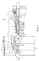
- Gas turbine engine 2 is a two-spool turbofan that generally incorporates a fan section 4, a compressor section 6, a combustor section 8 and a turbine section 10. Vanes 51 may be disposed throughout the gas turbine engine 2.
- Alternative engines include, for example, an augmentor section among other systems or features.
- fan section 4 drives air along a bypass flow-path B while compressor section 6 drives air along a core flow-path C for compression and communication into combustor section 8 then expansion through turbine section 10.
- a gas turbine engine may comprise an industrial gas turbine (IGT) or a geared aircraft engine, such as a geared turbofan, or non-geared aircraft engine, such as a turbofan, or may comprise any gas turbine engine as desired.
- IGT industrial gas turbine
- a geared aircraft engine such as a geared turbofan
- non-geared aircraft engine such as a turbofan
- Gas turbine engine 2 generally comprises a low speed spool 12 and a high speed spool 14 mounted for rotation about an engine central longitudinal axis X-X' relative to an engine static structure 16 via several bearing systems 18-1, 18-2, and 18-3. It should be understood that bearing systems is alternatively or additionally provided at locations, including for example, bearing system 18-1, bearing system 18-2, and bearing system 18-3.
- Low speed spool 12 generally comprises an inner shaft 20 that interconnects a fan 22, a low pressure compressor section 24, e.g., a first compressor section, and a low pressure turbine section 26, e.g., a second turbine section.
- Inner shaft 20 is connected to fan 22 through a geared architecture 28 that drives the fan 22 at a lower speed than low speed spool 12.
- Geared architecture 28 comprises a gear assembly 42 enclosed within a gear housing 44.
- Gear assembly 42 couples the inner shaft 20 to a rotating fan structure.
- High speed spool 14 comprises an outer shaft 80 that interconnects a high pressure compressor section 32, e.g., second compressor section, and high pressure turbine section 34, e.g., first turbine section.
- a combustor 36 is located between high pressure compressor section 32 and high pressure turbine section 34.
- a mid-turbine frame 38 of engine static structure 16 is located generally between high pressure turbine section 34 and low pressure turbine section 26.
- Mid-turbine frame 38 supports one or more bearing systems 18, such as 18-3, in turbine section 10.
- Inner shaft 20 and outer shaft 80 are concentric and rotate via bearing systems 18 about the engine central longitudinal axis X-X', which is collinear with their longitudinal axes.
- a "high pressure" compressor or turbine experiences a higher pressure than a corresponding "low pressure” compressor or turbine.
- the core airflow C is compressed by low pressure compressor section 24 then high pressure compressor section 32, mixed and burned with fuel in combustor 36, then expanded over high pressure turbine section 34 and low pressure turbine section 26.
- Mid-turbine frame 38 includes surface structures 40, which are in the core airflow path. Turbines 26, 34 rotationally drive the respective low speed spool 12 and high speed spool 14 in response to the expansion.
- Gas turbine engine 2 is, for example, a high-bypass geared aircraft engine.
- the bypass ratio of gas turbine engine 2 is optionally greater than about six (6).
- the bypass ratio of gas turbine engine 2 is optionally greater than ten (10).
- Geared architecture 28 is an epicyclic gear train, such as a star gear system, e.g., sun gear in meshing engagement with a plurality of star gears supported by a carrier and in meshing engagement with a ring gear, or other gear system.
- Geared architecture 28 has a gear reduction ratio of greater than about 2.3 and low pressure turbine section 26 has a pressure ratio that is greater than about five (5).
- the bypass ratio of gas turbine engine 2 is greater than about ten (10:1).
- the diameter of fan 22 is significantly larger than that of the low pressure compressor section 24, and the low pressure turbine section 26 has a pressure ratio that is greater than about 5:1.
- Low pressure turbine section 26 pressure ratio is measured prior to inlet of low pressure turbine section 26 as related to the pressure at the outlet of low pressure turbine section 26 prior to an exhaust nozzle. It should be understood, however, that the above parameters are exemplary of a suitable geared architecture engine and that the present disclosure contemplates other turbine engines including direct drive turbofans.
- An engine 2 may comprise a rotor blade 68 or a stator vane 51.
- Stator vanes 51 may be arranged circumferentially about the engine central longitudinal axis X-X'.
- Stator vanes 51 may be variable, meaning the angle of attack of the airfoil of the stator vane may be variable relative to the airflow proximate to the stator vanes 51.
- the angle of attack of the variable stator vane 51 may be variable during operation, or may be fixable for operation, for instance, being variable during maintenance or construction and fixable for operation. In various embodiments, it may be desirable to affix a variable vane 51 in fixed position (e.g., constant angle of attack).
- a fir tree coupling for interfacing an airfoil (e.g., a blade) with a turbine disk of a gas turbine engine.
- a fir tree coupling may comprise a load beam having a longitudinal axis, a base, a first side, and a second side.
- the fir tree coupling may comprise a plurality of teeth running parallel or substantially parallel the load beam longitudinal axis and disposed on the first side and the second side of the load beam.
- the teeth have bearing surfaces which transmit loads at the blade-disk interface.
- the blade-disk interface load may be concentrated as a high stress in an attachment fillet disposed between the teeth of the fir tree coupling.
- the base of the fir tree coupling may comprise rails extending from the base between the first side and the second side which may reduce attachment fillet stress and tend to mitigate LCF.
- a blade assembly may comprise a fir tree coupling, an airfoil, and a platform having a dorsal and a ventral surface.
- the airfoil extends from the dorsal surface of the platform and the fir tree coupling extends from the ventral surface of the platform.
- the blade assembly is coupled to a turbine disk by the fir tree coupling which transmits the centrifugal force acting on the airfoil resulting from the airfoil's rotation about the gas turbine engine shaft to the turbine disk through the bearing surfaces of the fir tree coupling teeth.
- the centrifugal force induces bending in the teeth which tends to concentrate stresses at the lower most attachment fillet between the teeth.
- the aforesaid stress concentrations may propagate cracking which tends to drive LCF.
- rails extending from the base of the fir tree coupling resist tooth bending by compression of the rails, reducing attachment fillet stresses, and thereby tending to mitigating LCF.
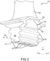
- a blade assembly 100 comprises an airfoil 102, a platform 104, and a fir tree coupling 200.
- Airfoil 102 extends from dorsal surface 106 of platform 104.
- Fir tree coupling 200 includes teeth 202 and base 210 and extends from ventral surface 108 of platform 104.
- Xyz axes are shown for convenience, with z extending perpendicular to the xy plane. In that regard, a measurement point displaced in the positive z-axis direction from a given reference point may be considered “above” or on "top" of the given reference point.
- a measurement point displaced in the negative z-axis direction from the given reference point may be considered “below” or on “bottom” of the given reference point.
- the terms “top” and “bottom” may refer to relative positions along the z-axis.
- airfoil 102 is on top of platform 104 and fir tree coupling 200 is below airfoil 102.
- Rails 204 extend across the y axis below (with reference to the z-axis) the base 210 of fir tree coupling 200.
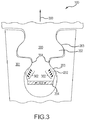
- Blade assembly 100 is inserted into turbine disk 301 and coupled by fir tree coupling 200.
- centrifugal force 300 is generated, which is transmitted into disk 301 at bearing surfaces 203 of teeth 202, tending to induce bending 302, which tends to concentrate stress at attachment fillets 304.
- the compressive force 303 is resisted by rails 204 and tends to reduce stress at attachment fillets 304.
- a fir tree coupling 200 is shown to comprise a load beam 206 having a first side 212 and a second side 214, a base 210, and a longitudinal axis 207.
- the load beam may further comprise a top surface 208.
- a plurality of teeth 202 disposed on the first side 212 and second side 214 extend laterally (along the y-axis) and run parallel to the longitudinal axis 207 (along the x-axis).
- Rails 204 extend below (along the z-axis) base 210 and run between the first side 212 and second side 214 of the load beam.
- a fir tree coupling may be made of metal, an alloy, nickel, nickel alloy, titanium, or titanium alloy.
- a fir tree coupling may be surface treated or may be heat treated by precipitation hardening or age hardening.
- a fir tree coupling may be a precipitation-hardening austenite nickel-chromium superalloy such as that sold commercially as Inconel®.
- a fir tree coupling may be a single crystal or monocrystalline solid.
- cooling passages 216 in the base of a fir tree coupling may be disposed between rails such as rails 204 and extend upward (along the z-axis) from the base through the load beam to a top surface such as top surface 208 of a fir tree coupling. Cooling passages 216 may extend radially outward through the airfoil.
- Cooling passages 216 may have an opening in a base such as base 210 and may form part of a cooling system for a blade assembly such as blade assembly 100 and be in fluid communication with a second cooling passage disposed within a platform such as platform 104 or an airfoil such as airfoil 102.
- rails such as rails 204 may be perpendicular to the longitudinal axis of a load beam such as longitudinal axis 207.
- rails such as rails 217 and 218 may be disposed at an angle to the longitudinal axis of a load beam such as longitudinal axis 207.
- rails such as rails 204 may be disposed proximate cooling passages such as cooling passages 216.
- cooling passages may be skewed relative to the longitudinal axis.
- rails such as rails 204 may comprise at least one of a tapered sidewall 600 wherein the tapered sidewall extends below the base at an angle, a convex sidewall 602 wherein the rail extension below the base is bounded by a convex curvature of the convex sidewall, a vertical sidewall 604 wherein the rail sidewall extends perpendicular below the base, a sidewall comprising a sidewall step 608 wherein the sidewall has a step 609 cut into a portion of the rail thickness, or a concave sidewall 610 wherein the rail sidewall extension below the base is bounded by a concave curvature of the sidewall.
- a tapered sidewall 600 wherein the tapered sidewall extends below the base at an angle
- a convex sidewall 602 wherein the rail extension below the base is bounded by a convex curvature of the convex sidewall
- a vertical sidewall 604 wherein the rail sidewall extends perpendicular
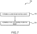
- a method 700 of manufacturing a fir tree coupling may comprise forming a load beam 702 having a longitudinal axis, a base, a first side, a second side, a tooth running parallel to the longitudinal axis and disposed on the first side of the load beam, and forming a rail 704 extending across the base of the load beam between the first side and the second side.
- Forming may comprise subtractive manufacturing such as casting, forging, milling, grinding, machining, and the like.
- Forming may also comprise additive manufacturing, such as electron-beam melting, selective laser sintering, electron-beam freeform fabrication, and the like.
- Forming may also comprises joining such as welding, brazing and/or other suitable methods.
- references to "one embodiment”, “an embodiment”, “various embodiments”, etc. indicate that the embodiment described may include a particular feature, structure, or characteristic, but every embodiment may not necessarily include the particular feature, structure, or characteristic. Moreover, such phrases are not necessarily referring to the same embodiment. Further, when a particular feature, structure, or characteristic is described in connection with an embodiment, it is submitted that it is within the knowledge of one skilled in the art to affect such feature, structure, or characteristic in connection with other embodiments whether or not explicitly described. After reading the description, it will be apparent to one skilled in the relevant art(s) how to implement the disclosure in alternative embodiments.
Landscapes
- Engineering & Computer Science (AREA)
- Mechanical Engineering (AREA)
- General Engineering & Computer Science (AREA)
- Architecture (AREA)
- Turbine Rotor Nozzle Sealing (AREA)
Applications Claiming Priority (1)
| Application Number | Priority Date | Filing Date | Title |
|---|---|---|---|
| US15/009,328 US10077665B2 (en) | 2016-01-28 | 2016-01-28 | Turbine blade attachment rails for attachment fillet stress reduction |
Publications (2)
| Publication Number | Publication Date |
|---|---|
| EP3199765A1 true EP3199765A1 (fr) | 2017-08-02 |
| EP3199765B1 EP3199765B1 (fr) | 2020-09-30 |
Family
ID=57909559
Family Applications (1)
| Application Number | Title | Priority Date | Filing Date |
|---|---|---|---|
| EP17153625.3A Active EP3199765B1 (fr) | 2016-01-28 | 2017-01-27 | Rails de fixation d'aube de turbine permettant de réduire la contrainte sur le congé de raccordement |
Country Status (2)
| Country | Link |
|---|---|
| US (1) | US10077665B2 (fr) |
| EP (1) | EP3199765B1 (fr) |
Cited By (2)
| Publication number | Priority date | Publication date | Assignee | Title |
|---|---|---|---|---|
| EP3594450A1 (fr) * | 2018-07-09 | 2020-01-15 | Rolls-Royce plc | Pale pour moteur de turbine à gaz |
| FR3087479A1 (fr) * | 2018-10-23 | 2020-04-24 | Safran Aircraft Engines | Aube de turbomachine |
Citations (2)
| Publication number | Priority date | Publication date | Assignee | Title |
|---|---|---|---|---|
| FR2275975A5 (fr) * | 1973-03-20 | 1976-01-16 | Snecma | Perfectionnements au refroidissement d'aubes de turbines a gaz |
| US7708525B2 (en) * | 2005-02-17 | 2010-05-04 | United Technologies Corporation | Industrial gas turbine blade assembly |
Family Cites Families (12)
| Publication number | Priority date | Publication date | Assignee | Title |
|---|---|---|---|---|
| NL92044C (fr) * | 1953-07-06 | |||
| US20050224144A1 (en) * | 2004-01-16 | 2005-10-13 | Tresa Pollock | Monocrystalline alloys with controlled partitioning |
| EP1614861A1 (fr) * | 2004-07-09 | 2006-01-11 | Siemens Aktiengesellschaft | Roue de turbine comprenant des aubes de turbine avec turbulateurs sur la surface radiale interne de la plate-forme |
| US7690896B2 (en) * | 2005-05-27 | 2010-04-06 | United Technologies Corporation | Gas turbine disk slots and gas turbine engine using same |
| JP4886735B2 (ja) * | 2008-05-26 | 2012-02-29 | 株式会社東芝 | タービン動翼組立体および蒸気タービン |
| US8573942B2 (en) * | 2008-11-25 | 2013-11-05 | Alstom Technology Ltd. | Axial retention of a platform seal |
| US9328622B2 (en) * | 2012-06-12 | 2016-05-03 | General Electric Company | Blade attachment assembly |
| DE102013214933A1 (de) * | 2013-07-30 | 2015-02-26 | MTU Aero Engines AG | Verfahren zum Montieren einer Gasturbinenschaufel in einer zugeordneten Aufnahme eines Rotorgrundkörpers |
| EP2873807A1 (fr) * | 2013-11-18 | 2015-05-20 | Siemens Aktiengesellschaft | Plaque de recouvrement, aube mobile, disque de roue, boulon et turbine à gaz |
| US20160146016A1 (en) * | 2014-11-24 | 2016-05-26 | General Electric Company | Rotor rim impingement cooling |
| US10018065B2 (en) * | 2015-09-04 | 2018-07-10 | Ansaldo Energia Ip Uk Limited | Flow control device for rotating flow supply system |
| FR3043133B1 (fr) * | 2015-10-30 | 2020-09-18 | Turbomeca | Aube de turbomachine comprenant un pied etage et traverse par des cavites d'air de refroidissement |
-
2016
- 2016-01-28 US US15/009,328 patent/US10077665B2/en active Active
-
2017
- 2017-01-27 EP EP17153625.3A patent/EP3199765B1/fr active Active
Patent Citations (2)
| Publication number | Priority date | Publication date | Assignee | Title |
|---|---|---|---|---|
| FR2275975A5 (fr) * | 1973-03-20 | 1976-01-16 | Snecma | Perfectionnements au refroidissement d'aubes de turbines a gaz |
| US7708525B2 (en) * | 2005-02-17 | 2010-05-04 | United Technologies Corporation | Industrial gas turbine blade assembly |
Cited By (3)
| Publication number | Priority date | Publication date | Assignee | Title |
|---|---|---|---|---|
| EP3594450A1 (fr) * | 2018-07-09 | 2020-01-15 | Rolls-Royce plc | Pale pour moteur de turbine à gaz |
| FR3087479A1 (fr) * | 2018-10-23 | 2020-04-24 | Safran Aircraft Engines | Aube de turbomachine |
| US11156107B2 (en) | 2018-10-23 | 2021-10-26 | Safran Aircraft Engines | Turbomachine blade |
Also Published As
| Publication number | Publication date |
|---|---|
| EP3199765B1 (fr) | 2020-09-30 |
| US10077665B2 (en) | 2018-09-18 |
| US20170218775A1 (en) | 2017-08-03 |
Similar Documents
| Publication | Publication Date | Title |
|---|---|---|
| EP3199764B1 (fr) | Couplage en sapin pour aube de turbine et procédé de fabrication correspondant | |
| US9988913B2 (en) | Using inserts to balance heat transfer and stress in high temperature alloys | |
| EP2986822B1 (fr) | Rotors à aubes désaccordées par modification du module de young | |
| US10036259B2 (en) | Turbine blade having film cooling hole arrangement | |
| USRE49382E1 (en) | High pressure rotor disk | |
| US10792771B2 (en) | Method of making integrally bladed rotor | |
| EP2867471A2 (fr) | Profil d'aile portante pour aube de turbine de moteur à turbine à gaz | |
| US10060268B2 (en) | Turbine blade having film cooling hole arrangement | |
| EP3231994B1 (fr) | Compresseur à débit axial pour un moteur à turbine à gaz | |
| EP2993304B1 (fr) | Composant de moteur à turbine à gaz avec trou formant un film de refroidissement | |
| WO2014137686A1 (fr) | Refroidissement de turbine à gaz à profil aérodynamique haute portance dans une zone de stagnation | |
| EP3453484A1 (fr) | Procédé de fabrication d'un rotor à aubes intégrées | |
| EP3103965B1 (fr) | Systeme de fixation pour une etancheite externe d'extremite d'aube de moteur de turbine | |
| EP3199765B1 (fr) | Rails de fixation d'aube de turbine permettant de réduire la contrainte sur le congé de raccordement | |
| US20150308449A1 (en) | Gas turbine engine component with brazed cover | |
| EP3098387B1 (fr) | Amortisseur à tolérance de pannes d'installation | |
| EP3037627B1 (fr) | Géométrie matérielle permettant d'augmenter le chevauchement de pièce et de maintien du jeu | |
| EP3056675A1 (fr) | Systèmes et procédés de refroidissement d'aube | |
| EP3299587B1 (fr) | Aube de moteur à turbine à gaz | |
| WO2014007934A1 (fr) | Profil de surface portante d'ailette de turbine d'un moteur à turbines à gaz | |
| US11098591B1 (en) | Turbine blade with contoured fillet | |
| EP3550105B1 (fr) | Disque de rotor de moteur à turbine à gaz | |
| US11634990B2 (en) | Component with mechanical locking features incorporating adaptive cooling and method of making | |
| EP3438415A1 (fr) | Procédés de fabrication d'un rotor à aubes intégrées par soudage par friction |
Legal Events
| Date | Code | Title | Description |
|---|---|---|---|
| PUAI | Public reference made under article 153(3) epc to a published international application that has entered the european phase |
Free format text: ORIGINAL CODE: 0009012 |
|
| STAA | Information on the status of an ep patent application or granted ep patent |
Free format text: STATUS: THE APPLICATION HAS BEEN PUBLISHED |
|
| AK | Designated contracting states |
Kind code of ref document: A1 Designated state(s): AL AT BE BG CH CY CZ DE DK EE ES FI FR GB GR HR HU IE IS IT LI LT LU LV MC MK MT NL NO PL PT RO RS SE SI SK SM TR |
|
| AX | Request for extension of the european patent |
Extension state: BA ME |
|
| STAA | Information on the status of an ep patent application or granted ep patent |
Free format text: STATUS: REQUEST FOR EXAMINATION WAS MADE |
|
| 17P | Request for examination filed |
Effective date: 20180202 |
|
| RBV | Designated contracting states (corrected) |
Designated state(s): AL AT BE BG CH CY CZ DE DK EE ES FI FR GB GR HR HU IE IS IT LI LT LU LV MC MK MT NL NO PL PT RO RS SE SI SK SM TR |
|
| STAA | Information on the status of an ep patent application or granted ep patent |
Free format text: STATUS: EXAMINATION IS IN PROGRESS |
|
| 17Q | First examination report despatched |
Effective date: 20180531 |
|
| GRAP | Despatch of communication of intention to grant a patent |
Free format text: ORIGINAL CODE: EPIDOSNIGR1 |
|
| STAA | Information on the status of an ep patent application or granted ep patent |
Free format text: STATUS: GRANT OF PATENT IS INTENDED |
|
| INTG | Intention to grant announced |
Effective date: 20200508 |
|
| RIN1 | Information on inventor provided before grant (corrected) |
Inventor name: HASSAN, MOHAMED Inventor name: THISTLE, CHARLES |
|
| GRAS | Grant fee paid |
Free format text: ORIGINAL CODE: EPIDOSNIGR3 |
|
| GRAA | (expected) grant |
Free format text: ORIGINAL CODE: 0009210 |
|
| STAA | Information on the status of an ep patent application or granted ep patent |
Free format text: STATUS: THE PATENT HAS BEEN GRANTED |
|
| AK | Designated contracting states |
Kind code of ref document: B1 Designated state(s): AL AT BE BG CH CY CZ DE DK EE ES FI FR GB GR HR HU IE IS IT LI LT LU LV MC MK MT NL NO PL PT RO RS SE SI SK SM TR |
|
| REG | Reference to a national code |
Ref country code: GB Ref legal event code: FG4D Ref country code: CH Ref legal event code: EP |
|
| REG | Reference to a national code |
Ref country code: AT Ref legal event code: REF Ref document number: 1318989 Country of ref document: AT Kind code of ref document: T Effective date: 20201015 |
|
| REG | Reference to a national code |
Ref country code: DE Ref legal event code: R096 Ref document number: 602017024413 Country of ref document: DE |
|
| REG | Reference to a national code |
Ref country code: IE Ref legal event code: FG4D |
|
| PG25 | Lapsed in a contracting state [announced via postgrant information from national office to epo] |
Ref country code: BG Free format text: LAPSE BECAUSE OF FAILURE TO SUBMIT A TRANSLATION OF THE DESCRIPTION OR TO PAY THE FEE WITHIN THE PRESCRIBED TIME-LIMIT Effective date: 20201230 Ref country code: SE Free format text: LAPSE BECAUSE OF FAILURE TO SUBMIT A TRANSLATION OF THE DESCRIPTION OR TO PAY THE FEE WITHIN THE PRESCRIBED TIME-LIMIT Effective date: 20200930 Ref country code: HR Free format text: LAPSE BECAUSE OF FAILURE TO SUBMIT A TRANSLATION OF THE DESCRIPTION OR TO PAY THE FEE WITHIN THE PRESCRIBED TIME-LIMIT Effective date: 20200930 Ref country code: NO Free format text: LAPSE BECAUSE OF FAILURE TO SUBMIT A TRANSLATION OF THE DESCRIPTION OR TO PAY THE FEE WITHIN THE PRESCRIBED TIME-LIMIT Effective date: 20201230 Ref country code: FI Free format text: LAPSE BECAUSE OF FAILURE TO SUBMIT A TRANSLATION OF THE DESCRIPTION OR TO PAY THE FEE WITHIN THE PRESCRIBED TIME-LIMIT Effective date: 20200930 Ref country code: GR Free format text: LAPSE BECAUSE OF FAILURE TO SUBMIT A TRANSLATION OF THE DESCRIPTION OR TO PAY THE FEE WITHIN THE PRESCRIBED TIME-LIMIT Effective date: 20201231 |
|
| REG | Reference to a national code |
Ref country code: AT Ref legal event code: MK05 Ref document number: 1318989 Country of ref document: AT Kind code of ref document: T Effective date: 20200930 |
|
| PG25 | Lapsed in a contracting state [announced via postgrant information from national office to epo] |
Ref country code: RS Free format text: LAPSE BECAUSE OF FAILURE TO SUBMIT A TRANSLATION OF THE DESCRIPTION OR TO PAY THE FEE WITHIN THE PRESCRIBED TIME-LIMIT Effective date: 20200930 Ref country code: LV Free format text: LAPSE BECAUSE OF FAILURE TO SUBMIT A TRANSLATION OF THE DESCRIPTION OR TO PAY THE FEE WITHIN THE PRESCRIBED TIME-LIMIT Effective date: 20200930 |
|
| REG | Reference to a national code |
Ref country code: NL Ref legal event code: MP Effective date: 20200930 |
|
| RAP2 | Party data changed (patent owner data changed or rights of a patent transferred) |
Owner name: RAYTHEON TECHNOLOGIES CORPORATION |
|
| REG | Reference to a national code |
Ref country code: LT Ref legal event code: MG4D |
|
| PG25 | Lapsed in a contracting state [announced via postgrant information from national office to epo] |
Ref country code: LT Free format text: LAPSE BECAUSE OF FAILURE TO SUBMIT A TRANSLATION OF THE DESCRIPTION OR TO PAY THE FEE WITHIN THE PRESCRIBED TIME-LIMIT Effective date: 20200930 Ref country code: NL Free format text: LAPSE BECAUSE OF FAILURE TO SUBMIT A TRANSLATION OF THE DESCRIPTION OR TO PAY THE FEE WITHIN THE PRESCRIBED TIME-LIMIT Effective date: 20200930 Ref country code: RO Free format text: LAPSE BECAUSE OF FAILURE TO SUBMIT A TRANSLATION OF THE DESCRIPTION OR TO PAY THE FEE WITHIN THE PRESCRIBED TIME-LIMIT Effective date: 20200930 Ref country code: PT Free format text: LAPSE BECAUSE OF FAILURE TO SUBMIT A TRANSLATION OF THE DESCRIPTION OR TO PAY THE FEE WITHIN THE PRESCRIBED TIME-LIMIT Effective date: 20210201 Ref country code: CZ Free format text: LAPSE BECAUSE OF FAILURE TO SUBMIT A TRANSLATION OF THE DESCRIPTION OR TO PAY THE FEE WITHIN THE PRESCRIBED TIME-LIMIT Effective date: 20200930 Ref country code: EE Free format text: LAPSE BECAUSE OF FAILURE TO SUBMIT A TRANSLATION OF THE DESCRIPTION OR TO PAY THE FEE WITHIN THE PRESCRIBED TIME-LIMIT Effective date: 20200930 Ref country code: SM Free format text: LAPSE BECAUSE OF FAILURE TO SUBMIT A TRANSLATION OF THE DESCRIPTION OR TO PAY THE FEE WITHIN THE PRESCRIBED TIME-LIMIT Effective date: 20200930 |
|
| PG25 | Lapsed in a contracting state [announced via postgrant information from national office to epo] |
Ref country code: AL Free format text: LAPSE BECAUSE OF FAILURE TO SUBMIT A TRANSLATION OF THE DESCRIPTION OR TO PAY THE FEE WITHIN THE PRESCRIBED TIME-LIMIT Effective date: 20200930 Ref country code: AT Free format text: LAPSE BECAUSE OF FAILURE TO SUBMIT A TRANSLATION OF THE DESCRIPTION OR TO PAY THE FEE WITHIN THE PRESCRIBED TIME-LIMIT Effective date: 20200930 Ref country code: ES Free format text: LAPSE BECAUSE OF FAILURE TO SUBMIT A TRANSLATION OF THE DESCRIPTION OR TO PAY THE FEE WITHIN THE PRESCRIBED TIME-LIMIT Effective date: 20200930 Ref country code: PL Free format text: LAPSE BECAUSE OF FAILURE TO SUBMIT A TRANSLATION OF THE DESCRIPTION OR TO PAY THE FEE WITHIN THE PRESCRIBED TIME-LIMIT Effective date: 20200930 Ref country code: IS Free format text: LAPSE BECAUSE OF FAILURE TO SUBMIT A TRANSLATION OF THE DESCRIPTION OR TO PAY THE FEE WITHIN THE PRESCRIBED TIME-LIMIT Effective date: 20210130 |
|
| PG25 | Lapsed in a contracting state [announced via postgrant information from national office to epo] |
Ref country code: SK Free format text: LAPSE BECAUSE OF FAILURE TO SUBMIT A TRANSLATION OF THE DESCRIPTION OR TO PAY THE FEE WITHIN THE PRESCRIBED TIME-LIMIT Effective date: 20200930 |
|
| REG | Reference to a national code |
Ref country code: DE Ref legal event code: R097 Ref document number: 602017024413 Country of ref document: DE |
|
| PLBE | No opposition filed within time limit |
Free format text: ORIGINAL CODE: 0009261 |
|
| STAA | Information on the status of an ep patent application or granted ep patent |
Free format text: STATUS: NO OPPOSITION FILED WITHIN TIME LIMIT |
|
| PG25 | Lapsed in a contracting state [announced via postgrant information from national office to epo] |
Ref country code: MC Free format text: LAPSE BECAUSE OF FAILURE TO SUBMIT A TRANSLATION OF THE DESCRIPTION OR TO PAY THE FEE WITHIN THE PRESCRIBED TIME-LIMIT Effective date: 20200930 Ref country code: DK Free format text: LAPSE BECAUSE OF FAILURE TO SUBMIT A TRANSLATION OF THE DESCRIPTION OR TO PAY THE FEE WITHIN THE PRESCRIBED TIME-LIMIT Effective date: 20200930 |
|
| REG | Reference to a national code |
Ref country code: CH Ref legal event code: PL |
|
| 26N | No opposition filed |
Effective date: 20210701 |
|
| PG25 | Lapsed in a contracting state [announced via postgrant information from national office to epo] |
Ref country code: LU Free format text: LAPSE BECAUSE OF NON-PAYMENT OF DUE FEES Effective date: 20210127 |
|
| REG | Reference to a national code |
Ref country code: BE Ref legal event code: MM Effective date: 20210131 |
|
| PG25 | Lapsed in a contracting state [announced via postgrant information from national office to epo] |
Ref country code: IT Free format text: LAPSE BECAUSE OF FAILURE TO SUBMIT A TRANSLATION OF THE DESCRIPTION OR TO PAY THE FEE WITHIN THE PRESCRIBED TIME-LIMIT Effective date: 20200930 |
|
| PG25 | Lapsed in a contracting state [announced via postgrant information from national office to epo] |
Ref country code: SI Free format text: LAPSE BECAUSE OF FAILURE TO SUBMIT A TRANSLATION OF THE DESCRIPTION OR TO PAY THE FEE WITHIN THE PRESCRIBED TIME-LIMIT Effective date: 20200930 Ref country code: CH Free format text: LAPSE BECAUSE OF NON-PAYMENT OF DUE FEES Effective date: 20210131 Ref country code: LI Free format text: LAPSE BECAUSE OF NON-PAYMENT OF DUE FEES Effective date: 20210131 |
|
| PG25 | Lapsed in a contracting state [announced via postgrant information from national office to epo] |
Ref country code: IE Free format text: LAPSE BECAUSE OF NON-PAYMENT OF DUE FEES Effective date: 20210127 |
|
| PG25 | Lapsed in a contracting state [announced via postgrant information from national office to epo] |
Ref country code: IS Free format text: LAPSE BECAUSE OF FAILURE TO SUBMIT A TRANSLATION OF THE DESCRIPTION OR TO PAY THE FEE WITHIN THE PRESCRIBED TIME-LIMIT Effective date: 20210130 |
|
| PG25 | Lapsed in a contracting state [announced via postgrant information from national office to epo] |
Ref country code: BE Free format text: LAPSE BECAUSE OF NON-PAYMENT OF DUE FEES Effective date: 20210131 |
|
| PG25 | Lapsed in a contracting state [announced via postgrant information from national office to epo] |
Ref country code: HU Free format text: LAPSE BECAUSE OF FAILURE TO SUBMIT A TRANSLATION OF THE DESCRIPTION OR TO PAY THE FEE WITHIN THE PRESCRIBED TIME-LIMIT; INVALID AB INITIO Effective date: 20170127 |
|
| P01 | Opt-out of the competence of the unified patent court (upc) registered |
Effective date: 20230520 |
|
| PG25 | Lapsed in a contracting state [announced via postgrant information from national office to epo] |
Ref country code: CY Free format text: LAPSE BECAUSE OF FAILURE TO SUBMIT A TRANSLATION OF THE DESCRIPTION OR TO PAY THE FEE WITHIN THE PRESCRIBED TIME-LIMIT Effective date: 20200930 |
|
| PGFP | Annual fee paid to national office [announced via postgrant information from national office to epo] |
Ref country code: GB Payment date: 20231219 Year of fee payment: 8 |
|
| PGFP | Annual fee paid to national office [announced via postgrant information from national office to epo] |
Ref country code: FR Payment date: 20231219 Year of fee payment: 8 |
|
| PG25 | Lapsed in a contracting state [announced via postgrant information from national office to epo] |
Ref country code: MK Free format text: LAPSE BECAUSE OF FAILURE TO SUBMIT A TRANSLATION OF THE DESCRIPTION OR TO PAY THE FEE WITHIN THE PRESCRIBED TIME-LIMIT Effective date: 20200930 |
|
| PGFP | Annual fee paid to national office [announced via postgrant information from national office to epo] |
Ref country code: DE Payment date: 20231219 Year of fee payment: 8 |