EP3199489A1 - Carbonated beverage filling method and device - Google Patents
Carbonated beverage filling method and device Download PDFInfo
- Publication number
- EP3199489A1 EP3199489A1 EP15844366.3A EP15844366A EP3199489A1 EP 3199489 A1 EP3199489 A1 EP 3199489A1 EP 15844366 A EP15844366 A EP 15844366A EP 3199489 A1 EP3199489 A1 EP 3199489A1
- Authority
- EP
- European Patent Office
- Prior art keywords
- container
- bottle
- preform
- carbonated drink
- coolant
- Prior art date
- Legal status (The legal status is an assumption and is not a legal conclusion. Google has not performed a legal analysis and makes no representation as to the accuracy of the status listed.)
- Granted
Links
Images





Classifications
-
- B—PERFORMING OPERATIONS; TRANSPORTING
- B67—OPENING, CLOSING OR CLEANING BOTTLES, JARS OR SIMILAR CONTAINERS; LIQUID HANDLING
- B67C—CLEANING, FILLING WITH LIQUIDS OR SEMILIQUIDS, OR EMPTYING, OF BOTTLES, JARS, CANS, CASKS, BARRELS, OR SIMILAR CONTAINERS, NOT OTHERWISE PROVIDED FOR; FUNNELS
- B67C3/00—Bottling liquids or semiliquids; Filling jars or cans with liquids or semiliquids using bottling or like apparatus; Filling casks or barrels with liquids or semiliquids
- B67C3/02—Bottling liquids or semiliquids; Filling jars or cans with liquids or semiliquids using bottling or like apparatus
- B67C3/22—Details
-
- B—PERFORMING OPERATIONS; TRANSPORTING
- B08—CLEANING
- B08B—CLEANING IN GENERAL; PREVENTION OF FOULING IN GENERAL
- B08B9/00—Cleaning hollow articles by methods or apparatus specially adapted thereto
- B08B9/08—Cleaning containers, e.g. tanks
- B08B9/20—Cleaning containers, e.g. tanks by using apparatus into or on to which containers, e.g. bottles, jars, cans are brought
- B08B9/28—Cleaning containers, e.g. tanks by using apparatus into or on to which containers, e.g. bottles, jars, cans are brought the apparatus cleaning by splash, spray, or jet application, with or without soaking
- B08B9/30—Cleaning containers, e.g. tanks by using apparatus into or on to which containers, e.g. bottles, jars, cans are brought the apparatus cleaning by splash, spray, or jet application, with or without soaking and having conveyors
- B08B9/32—Rotating conveyors
-
- A—HUMAN NECESSITIES
- A61—MEDICAL OR VETERINARY SCIENCE; HYGIENE
- A61L—METHODS OR APPARATUS FOR STERILISING MATERIALS OR OBJECTS IN GENERAL; DISINFECTION, STERILISATION OR DEODORISATION OF AIR; CHEMICAL ASPECTS OF BANDAGES, DRESSINGS, ABSORBENT PADS OR SURGICAL ARTICLES; MATERIALS FOR BANDAGES, DRESSINGS, ABSORBENT PADS OR SURGICAL ARTICLES
- A61L2/00—Disinfection or sterilisation of materials or objects, in general; Accessories therefor
- A61L2/16—Disinfection or sterilisation of materials or objects, in general; Accessories therefor using chemical substances
- A61L2/20—Gaseous substances, e.g. vapours
- A61L2/202—Ozone
-
- A—HUMAN NECESSITIES
- A61—MEDICAL OR VETERINARY SCIENCE; HYGIENE
- A61L—METHODS OR APPARATUS FOR STERILISING MATERIALS OR OBJECTS IN GENERAL; DISINFECTION, STERILISATION OR DEODORISATION OF AIR; CHEMICAL ASPECTS OF BANDAGES, DRESSINGS, ABSORBENT PADS OR SURGICAL ARTICLES; MATERIALS FOR BANDAGES, DRESSINGS, ABSORBENT PADS OR SURGICAL ARTICLES
- A61L2/00—Disinfection or sterilisation of materials or objects, in general; Accessories therefor
- A61L2/16—Disinfection or sterilisation of materials or objects, in general; Accessories therefor using chemical substances
- A61L2/20—Gaseous substances, e.g. vapours
- A61L2/208—Hydrogen peroxide
-
- A—HUMAN NECESSITIES
- A61—MEDICAL OR VETERINARY SCIENCE; HYGIENE
- A61L—METHODS OR APPARATUS FOR STERILISING MATERIALS OR OBJECTS IN GENERAL; DISINFECTION, STERILISATION OR DEODORISATION OF AIR; CHEMICAL ASPECTS OF BANDAGES, DRESSINGS, ABSORBENT PADS OR SURGICAL ARTICLES; MATERIALS FOR BANDAGES, DRESSINGS, ABSORBENT PADS OR SURGICAL ARTICLES
- A61L2/00—Disinfection or sterilisation of materials or objects, in general; Accessories therefor
- A61L2/16—Disinfection or sterilisation of materials or objects, in general; Accessories therefor using chemical substances
- A61L2/22—Phase substances, e.g. smokes or aerosols
-
- B—PERFORMING OPERATIONS; TRANSPORTING
- B08—CLEANING
- B08B—CLEANING IN GENERAL; PREVENTION OF FOULING IN GENERAL
- B08B9/00—Cleaning hollow articles by methods or apparatus specially adapted thereto
- B08B9/08—Cleaning containers, e.g. tanks
- B08B9/20—Cleaning containers, e.g. tanks by using apparatus into or on to which containers, e.g. bottles, jars, cans are brought
- B08B9/28—Cleaning containers, e.g. tanks by using apparatus into or on to which containers, e.g. bottles, jars, cans are brought the apparatus cleaning by splash, spray, or jet application, with or without soaking
- B08B9/283—Cleaning containers, e.g. tanks by using apparatus into or on to which containers, e.g. bottles, jars, cans are brought the apparatus cleaning by splash, spray, or jet application, with or without soaking by gas jets
-
- B—PERFORMING OPERATIONS; TRANSPORTING
- B29—WORKING OF PLASTICS; WORKING OF SUBSTANCES IN A PLASTIC STATE IN GENERAL
- B29C—SHAPING OR JOINING OF PLASTICS; SHAPING OF MATERIAL IN A PLASTIC STATE, NOT OTHERWISE PROVIDED FOR; AFTER-TREATMENT OF THE SHAPED PRODUCTS, e.g. REPAIRING
- B29C49/00—Blow-moulding, i.e. blowing a preform or parison to a desired shape within a mould; Apparatus therefor
- B29C49/02—Combined blow-moulding and manufacture of the preform or the parison
- B29C49/06—Injection blow-moulding
-
- B—PERFORMING OPERATIONS; TRANSPORTING
- B29—WORKING OF PLASTICS; WORKING OF SUBSTANCES IN A PLASTIC STATE IN GENERAL
- B29C—SHAPING OR JOINING OF PLASTICS; SHAPING OF MATERIAL IN A PLASTIC STATE, NOT OTHERWISE PROVIDED FOR; AFTER-TREATMENT OF THE SHAPED PRODUCTS, e.g. REPAIRING
- B29C49/00—Blow-moulding, i.e. blowing a preform or parison to a desired shape within a mould; Apparatus therefor
- B29C49/42—Component parts, details or accessories; Auxiliary operations
- B29C49/4273—Auxiliary operations after the blow-moulding operation not otherwise provided for
-
- B—PERFORMING OPERATIONS; TRANSPORTING
- B29—WORKING OF PLASTICS; WORKING OF SUBSTANCES IN A PLASTIC STATE IN GENERAL
- B29C—SHAPING OR JOINING OF PLASTICS; SHAPING OF MATERIAL IN A PLASTIC STATE, NOT OTHERWISE PROVIDED FOR; AFTER-TREATMENT OF THE SHAPED PRODUCTS, e.g. REPAIRING
- B29C49/00—Blow-moulding, i.e. blowing a preform or parison to a desired shape within a mould; Apparatus therefor
- B29C49/42—Component parts, details or accessories; Auxiliary operations
- B29C49/64—Heating or cooling preforms, parisons or blown articles
- B29C49/6409—Thermal conditioning of preforms
-
- B—PERFORMING OPERATIONS; TRANSPORTING
- B67—OPENING, CLOSING OR CLEANING BOTTLES, JARS OR SIMILAR CONTAINERS; LIQUID HANDLING
- B67C—CLEANING, FILLING WITH LIQUIDS OR SEMILIQUIDS, OR EMPTYING, OF BOTTLES, JARS, CANS, CASKS, BARRELS, OR SIMILAR CONTAINERS, NOT OTHERWISE PROVIDED FOR; FUNNELS
- B67C7/00—Concurrent cleaning, filling, and closing of bottles; Processes or devices for at least two of these operations
-
- B—PERFORMING OPERATIONS; TRANSPORTING
- B67—OPENING, CLOSING OR CLEANING BOTTLES, JARS OR SIMILAR CONTAINERS; LIQUID HANDLING
- B67C—CLEANING, FILLING WITH LIQUIDS OR SEMILIQUIDS, OR EMPTYING, OF BOTTLES, JARS, CANS, CASKS, BARRELS, OR SIMILAR CONTAINERS, NOT OTHERWISE PROVIDED FOR; FUNNELS
- B67C7/00—Concurrent cleaning, filling, and closing of bottles; Processes or devices for at least two of these operations
- B67C7/0006—Conveying; Synchronising
- B67C7/002—General lay-out of bottle-handling machines
-
- B—PERFORMING OPERATIONS; TRANSPORTING
- B67—OPENING, CLOSING OR CLEANING BOTTLES, JARS OR SIMILAR CONTAINERS; LIQUID HANDLING
- B67C—CLEANING, FILLING WITH LIQUIDS OR SEMILIQUIDS, OR EMPTYING, OF BOTTLES, JARS, CANS, CASKS, BARRELS, OR SIMILAR CONTAINERS, NOT OTHERWISE PROVIDED FOR; FUNNELS
- B67C7/00—Concurrent cleaning, filling, and closing of bottles; Processes or devices for at least two of these operations
- B67C7/0006—Conveying; Synchronising
- B67C7/004—Conveying; Synchronising the containers travelling along a circular path
- B67C7/0046—Infeed and outfeed devices
-
- B—PERFORMING OPERATIONS; TRANSPORTING
- B67—OPENING, CLOSING OR CLEANING BOTTLES, JARS OR SIMILAR CONTAINERS; LIQUID HANDLING
- B67C—CLEANING, FILLING WITH LIQUIDS OR SEMILIQUIDS, OR EMPTYING, OF BOTTLES, JARS, CANS, CASKS, BARRELS, OR SIMILAR CONTAINERS, NOT OTHERWISE PROVIDED FOR; FUNNELS
- B67C7/00—Concurrent cleaning, filling, and closing of bottles; Processes or devices for at least two of these operations
- B67C7/0073—Sterilising, aseptic filling and closing
-
- A—HUMAN NECESSITIES
- A61—MEDICAL OR VETERINARY SCIENCE; HYGIENE
- A61L—METHODS OR APPARATUS FOR STERILISING MATERIALS OR OBJECTS IN GENERAL; DISINFECTION, STERILISATION OR DEODORISATION OF AIR; CHEMICAL ASPECTS OF BANDAGES, DRESSINGS, ABSORBENT PADS OR SURGICAL ARTICLES; MATERIALS FOR BANDAGES, DRESSINGS, ABSORBENT PADS OR SURGICAL ARTICLES
- A61L2103/00—Materials or objects being the target of disinfection or sterilisation
- A61L2103/23—Containers other than laboratory or medical, e.g. bottles or mail
-
- A—HUMAN NECESSITIES
- A61—MEDICAL OR VETERINARY SCIENCE; HYGIENE
- A61L—METHODS OR APPARATUS FOR STERILISING MATERIALS OR OBJECTS IN GENERAL; DISINFECTION, STERILISATION OR DEODORISATION OF AIR; CHEMICAL ASPECTS OF BANDAGES, DRESSINGS, ABSORBENT PADS OR SURGICAL ARTICLES; MATERIALS FOR BANDAGES, DRESSINGS, ABSORBENT PADS OR SURGICAL ARTICLES
- A61L2202/00—Aspects relating to methods or apparatus for disinfecting or sterilising materials or objects
- A61L2202/10—Apparatus features
- A61L2202/15—Biocide distribution means, e.g. nozzles, pumps, manifolds, fans, baffles, sprayers
-
- B—PERFORMING OPERATIONS; TRANSPORTING
- B29—WORKING OF PLASTICS; WORKING OF SUBSTANCES IN A PLASTIC STATE IN GENERAL
- B29C—SHAPING OR JOINING OF PLASTICS; SHAPING OF MATERIAL IN A PLASTIC STATE, NOT OTHERWISE PROVIDED FOR; AFTER-TREATMENT OF THE SHAPED PRODUCTS, e.g. REPAIRING
- B29C49/00—Blow-moulding, i.e. blowing a preform or parison to a desired shape within a mould; Apparatus therefor
- B29C49/02—Combined blow-moulding and manufacture of the preform or the parison
- B29C2049/023—Combined blow-moulding and manufacture of the preform or the parison using inherent heat of the preform, i.e. 1 step blow moulding
-
- B—PERFORMING OPERATIONS; TRANSPORTING
- B29—WORKING OF PLASTICS; WORKING OF SUBSTANCES IN A PLASTIC STATE IN GENERAL
- B29K—INDEXING SCHEME ASSOCIATED WITH SUBCLASSES B29B, B29C OR B29D, RELATING TO MOULDING MATERIALS OR TO MATERIALS FOR MOULDS, REINFORCEMENTS, FILLERS OR PREFORMED PARTS, e.g. INSERTS
- B29K2067/00—Use of polyesters or derivatives thereof, as moulding material
- B29K2067/003—PET, i.e. poylethylene terephthalate
-
- B—PERFORMING OPERATIONS; TRANSPORTING
- B29—WORKING OF PLASTICS; WORKING OF SUBSTANCES IN A PLASTIC STATE IN GENERAL
- B29K—INDEXING SCHEME ASSOCIATED WITH SUBCLASSES B29B, B29C OR B29D, RELATING TO MOULDING MATERIALS OR TO MATERIALS FOR MOULDS, REINFORCEMENTS, FILLERS OR PREFORMED PARTS, e.g. INSERTS
- B29K2105/00—Condition, form or state of moulded material or of the material to be shaped
- B29K2105/25—Solid
- B29K2105/253—Preform
- B29K2105/258—Tubular
-
- B—PERFORMING OPERATIONS; TRANSPORTING
- B29—WORKING OF PLASTICS; WORKING OF SUBSTANCES IN A PLASTIC STATE IN GENERAL
- B29L—INDEXING SCHEME ASSOCIATED WITH SUBCLASS B29C, RELATING TO PARTICULAR ARTICLES
- B29L2031/00—Other particular articles
- B29L2031/712—Containers; Packaging elements or accessories, Packages
- B29L2031/7158—Bottles
-
- B—PERFORMING OPERATIONS; TRANSPORTING
- B67—OPENING, CLOSING OR CLEANING BOTTLES, JARS OR SIMILAR CONTAINERS; LIQUID HANDLING
- B67C—CLEANING, FILLING WITH LIQUIDS OR SEMILIQUIDS, OR EMPTYING, OF BOTTLES, JARS, CANS, CASKS, BARRELS, OR SIMILAR CONTAINERS, NOT OTHERWISE PROVIDED FOR; FUNNELS
- B67C3/00—Bottling liquids or semiliquids; Filling jars or cans with liquids or semiliquids using bottling or like apparatus; Filling casks or barrels with liquids or semiliquids
- B67C3/02—Bottling liquids or semiliquids; Filling jars or cans with liquids or semiliquids using bottling or like apparatus
- B67C3/22—Details
- B67C2003/227—Additional apparatus related to blow-moulding of the containers, e.g. a complete production line forming filled containers from preforms
-
- B—PERFORMING OPERATIONS; TRANSPORTING
- B67—OPENING, CLOSING OR CLEANING BOTTLES, JARS OR SIMILAR CONTAINERS; LIQUID HANDLING
- B67C—CLEANING, FILLING WITH LIQUIDS OR SEMILIQUIDS, OR EMPTYING, OF BOTTLES, JARS, CANS, CASKS, BARRELS, OR SIMILAR CONTAINERS, NOT OTHERWISE PROVIDED FOR; FUNNELS
- B67C3/00—Bottling liquids or semiliquids; Filling jars or cans with liquids or semiliquids using bottling or like apparatus; Filling casks or barrels with liquids or semiliquids
- B67C3/02—Bottling liquids or semiliquids; Filling jars or cans with liquids or semiliquids using bottling or like apparatus
- B67C3/22—Details
- B67C2003/228—Aseptic features
Definitions
- the present invention relates to a carbonated drink filling method and a carbonated drink filling system.
- a preform is continuously transferred and introduced into a heating furnace, heated in the heating furnace to a temperature for molding the preform into a bottle and molded into a bottle in a molding die after the preform exits the heating furnace.
- the bottle is then sterilized and inverted. Water is then injected into the bottle to wash the interior of the bottle and at the same time is injected to the bottom of the bottle to cool the bottom of the bottle. After that, the bottle is restored to the upright position and then is filled with a carbonated drink.
- the bottom of the bottle can be quickly cooled.
- the bottom of the bottle is not deformed, and thus the stability of the bottle can be improved (see Patent Literature 1, for example).
- Patent Literature 1 Japanese Patent Laid-Open No. 2013-237484
- the bottle is transferred in the inverted position, and water is injected into the bottle for washing and at the same time is injected to the bottom of the bottle for cooling.
- the bottle molded in the upright position needs to be inverted and then restored to the upright position. This leads to an increase in complexity of the structure of the manufacturing line and an increase in equipment cost.
- An object of the present invention is to solve the problem described above.
- the present invention is configured as described below.
- the invention defined in claim 1 adopts a carbonated drink filling method, wherein a preform (1) is continuously transferred and is introduced into a heating furnace (33), the preform (1) is heated to a temperature for molding the preform into a container (2) in the heating furnace (33), the preform (1) is molded into the container (2) in a molding die (4) after the preform (1) exits the heating furnace (33), the container (2) is conveyed in an upright position, a coolant (F) is injected to a bottom (2b) of the container (2) to cool the bottom (2b) of the container (2), the container (2) is filled with a carbonated drink (a) through a mouth portion (2a) of the container (2), and the mouth portion (2a) is then sealed, the coolant (F) being injected in the cooling to the bottom (2b) of the container (2) from a nozzle opening on either or both sides of a conveyance line of the container (2), and the nozzle opening being directed diagonally upward to the bottom (2b) of the container (2) in such a manner that an extension of
- the container (2) in the carbonated drink filling method according to claim 1, may be subjected to a sterilization process before the container (2) is filled with the carbonated drink (a), and the bottom (2b) of the container (a) may be cooled before and/or after the sterilization process.
- the container (2) in the carbonated drink filling method according to claim 1, may be subjected to a sterilization process before the container (2) is filled with the carbonated drink (a), the container (2) is subjected to water rinsing after the sterilization process, and the bottom (2b) of the container (2) may be cooled after the water rinsing.
- the invention defined in claim 4 adopts a carbonated drink filling system, comprising: a transfer device that transfers a preform (1) and a container (2) from where the preform (1) is supplied and molded into the container (2) to where the container (2) is filled with a carbonated drink (a) and sealed; a heating furnace (33) that heats the preform (1) to a molding temperature; a blow molding die (4) that blow-molds the preform (1) into the container (2); a coolant injection nozzle (28) that injects a coolant (F) to a bottom (2b) of the container (2) discharged from the blow molding die (4) in an upright position to cool the bottom (2b) of the container (2); a filler (39) that fills the container (2) with the carbonated drink (a) through a mouth portion (2a) of the container (2); and a capper (40) that seals the mouth portion (2a) of the container (2), the heating furnace (33), the blow molding die (4), the coolant injection nozzle (28), the filler (39) and the capper
- a sterilization device (30) that performs a sterilization process on the container (2) may be provided upstream of the filler (39), and the coolant injection nozzle (28) may be provided upstream and/or downstream of the sterilization device (30).
- a sterilization device (30) that performs a sterilization process on the container (2) may be provided upstream of the filler (39), a water rinsing device may be provided downstream of the sterilization device (30), and the coolant injection nozzle (28) may be provided between the water rinsing device and the filler.
- a preform (1) is continuously transferred and is introduced into a heating furnace (33), the preform (1) is heated to a temperature for molding the preform (1) into a container (2) in the heating furnace (33), the preform (1) is molded into the container (2) in a molding die (4) after the preform (1) exits the heating furnace(33), the container (2) is conveyed in an upright position, a coolant (f) is injected to a bottom (2b) of the container (2) to cool the bottom (2b) of the container (2), the container (2) is filled with a carbonated drink (a) through a mouth portion (2a) of the container (2), and the mouth portion (2a) is then sealed, the coolant (F) being injected in the cooling to the bottom (2b) of the container (2) from a nozzle opening on either or both sides of a conveyance line of the container (2), and the nozzle opening being directed diagonally upward to the bottom (2b) of the container (2) in such a manner that an extension of the nozzle opening intersects
- the bottom (2b) of the container (2) can be quickly cooled to prevent sagging or other deformation thereof, and even if the container (2) is filled with the carbonated drink (a) shortly after the container (2) is molded, outward deformation of the bottom (2b) of the container (2) can be prevented, and the stability of the container (2) can be improved.
- the structure of the manufacturing line of the bottled carbonated drink product can be simplified.
- the coolant (F) is injected to the bottom (2b) of the container (2) from a nozzle opening on either or both sides of a conveyance line of the container (2), and the nozzle opening is directed diagonally upward to the bottom (2b) of the container (2) in such a manner that an extension of the nozzle opening intersects with the conveyance line of the container (2).
- the coolant F is a liquid, such as water, droplets of the liquid are less likely to reach the mouth portion 2a of the bottle 2, so that the possibility that the droplets enter the bottle (2) to contaminate the interior of the bottle (2) is eliminated.
- a preform 1 shown in FIG. 1(A) is continuously conveyed at a desired velocity.
- the preform 1 is a bottomed tubular body similar to a test tube that is previously formed from PET (polyethylene terephthalate) by injection molding or the like.
- a mouth portion 2a similar to that of a bottle 2 shown in FIGS. 2(D) to 2(F) is formed on the preform 1 in an early stage of the molding of the preform 1.
- a male thread corresponding to a female thread on a cap 3 is formed on the mouth portion 2a during the molding of the preform 1.
- the preform 1 is heated to a temperature suitable for the subsequent blow molding by an infrared heater 18a or other heating device.
- the temperature is approximately between 90°C and 130°C.
- the temperature of the mouth portion 2a of the preform 1 is maintained to be equal to or lower than 70°C to prevent deformation, for example.
- the preform 1 is desirably suspended in an upright position (or inverted position) from a spindle (or mandrel) 43 inserted into the mouth portion 2a thereof and is conveyed while rotating with the spindle (or mandrel) 43.
- the preform 1 is uniformly heated by the infrared heater 18a.
- the preform 1 can be rotated and conveyed in the inverted position.
- the heated preform 1 is blow-molded into the bottle 2 in a die 4.
- the die 4 which is a molding die for blow molding, is clamped while being continuously rotated at the same speed as the transfer speed of the preform 1 and is opened after the blow molding of the preform 1 in the die 4 is completed.
- the preform 1 excluding the mouth portion 2a is uniformly heated to a temperature range suitable for molding in the heating step shown in FIG. 1(B) as described above, and the heated preform 1 is placed in the die 4, and an extension rod 5 is inserted in the preform 1 placed in the die 4 as shown in FIG. 1(C) .
- the die 4 is opened while being continuously transferred, and the bottle 2 as a finished product is removed from the die 4 in the upright position.
- the bottle just removed from the die 4 is hot and soft.
- a central portion of a bottom 2b of the bottle 2 is the thickest and thus takes some time to cool and set.
- a buckling 2c shown by the alternate long and two short dash line in FIGS. 2(E) and 2(F) can occur on the bottom 2b of the bottle.
- the buckling 2c is a phenomenon in which the bottom 2b of the bottle 2 that is still soft sags down in a protrusion form under a counter pressure applied immediately before filling the bottle with the carbonated drink or the internal pressure of the carbonated drink or the like supplied into the bottle.
- the bottom 2b of the bottle 2 is made thicker than the other parts to form a petaloid bottom to resist the pressure and thus is less susceptible to cooling and setting, so that the buckling 2c is more likely to occur. If the bottle 2 sets while the buckling 2c is not eliminated, the resulting bottle 2 is unstable and can fall.
- a drink such as the carbonated drink
- the bottom 2b of the bottle 2 is forcedly cooled by injecting a coolant F to the bottom 2b of the bottle 2 from outside the bottle 2.
- the coolant F may be a gas, such as air, or a liquid, such as water.
- a gas such as air
- a liquid such as water.
- aseptic air aseptic water
- a sterilizer containing a constituent such as peracetic acid, hydrogen peroxide, sodium hypochlorite, ozone water or acid water can be used as the coolant.
- a coolant injection nozzle 28 shown in FIG. 2(D) is used as a device for injecting the coolant F to the bottom 2b of the bottle 2.
- Coolant injection nozzles 28 are arranged on the opposite sides of the conveyance line of the bottle 2, and nozzle openings of the coolant injection nozzle 28 are directed diagonally upward to the bottom 2b of the bottle 2 in such a manner that the extensions of the nozzle openings intersect with the conveyance line of the bottle 2.
- an alternate long and short dash line 28a indicates the centerline of the nozzle opening.
- a large number of coolant injection nozzles 28 are arranged on the opposite sides of the bottle 2 being conveyed along the direction of conveyance of the bottle 2, as shown in FIG. 4 .
- the coolant injection nozzles are arranged in two rows in a staggered configuration.
- the coolant injection nozzles may also be arranged in a plurality of rows in the vertical direction, as required.
- the bottom 2b of the bottle 2 conveyed at a high speed is efficiently cooled and quickly sets, and thus, the buckling 2c is prevented from occurring.
- the nozzle openings on the opposite sides of the conveyance line of the bottle 2 are directed diagonally upward to the bottom 2b of the bottle 2 in such a manner that the extensions of the nozzle openings intersect with the conveyance line of the bottle 2, even when the coolant F is a liquid, such as water, droplets of the liquid are less likely to reach the mouth portion 2a of the bottle 2, so that the possibility of entry of the droplets to the bottle 2 is eliminated.
- the coolant F is a gas, such as air, as shown in FIG. 3
- the gas as the coolant F may be injected from the nozzle opening of the coolant injection nozzle 28 directly opposed to the bottom 2b of the bottle 2. If the coolant F is a gas, the possibility that the coolant F injected from the nozzle opening enters the bottle 2 is low, and if the coolant F is air, the coolant F is harmless even if the coolant F enters the bottle 2.
- the cooling with a gas can also prevent occurrence of the buckling 2c.
- the bottle 2 is filled with a carbonated drink "a" from a filling nozzle 10 as shown in FIG. 2(E) and then capped with a cap 3 serving as a lid as shown in FIG. 2(F) .
- a carbonated drink "a” from a filling nozzle 10 as shown in FIG. 2(E)
- a cap 3 serving as a lid as shown in FIG. 2(F) .
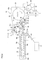
- a carbonated drink filling system that performs the carbonated drink filling method is configured as shown in FIG. 4 , for example.
- the carbonated drink filling system includes a preform supplying machine 11 (see FIG. 1(A) ) that successively supplies preforms 1 having the shape of a bottomed tube having the mouth portion 2a at predetermined intervals, a blow molding machine 12 (see FIGS. 1(B) and 1(C) ) that molds the preforms 1 into bottles 2, a cooling machine 29 (see FIG. 2(D) ) that forcedly cools the bottoms 2b of the molded bottles 2, and a filling machine 13 (see FIGS. 2(E) and 2(F) ) that fills the cooled bottles 2 with the drink "a" and seals the same with the caps 3.
- a preform supplying machine 11 see FIG. 1(A)
- a blow molding machine 12 see FIGS. 1(B) and 1(C)
- a cooling machine 29 see FIG. 2(D)
- a filling machine 13 see FIGS. 2(E) and 2(F)
- the blow molding machine 12 and the filling machine 13 of the carbonated drink filling system are surrounded by chambers 41a and 41b.
- the chamber 41a may not be a sealed structure but be a simple frame structure such as a shroud.
- a first conveying path for conveying the preform 1 or the like Between the preform supplying machine 11 and the filling machine 13, a first conveying path for conveying the preform 1 or the like, a second conveying path for conveying the die 4 (see FIG. 1(C) ) having the cavity C having the shape of the finished bottle 2, and a third conveying path for conveying the bottle 2 or the like molded in the die 4 are provided.
- the first to third conveying paths are coupled to each other, and a gripper (not shown) or the like that holds the preform 1 or bottle 2 during conveyance thereof is provided on these conveying paths.
- the first conveying path includes a preform conveyor 14 that successively supplies the preforms 1 at predetermined intervals.
- the first conveying path is provided with a train of wheels 15, 16 and 17 that receives and conveys the preforms 1 from a terminal end of the preform conveyor 14 and an endless chain 18 that receives and conveys the preform 1.
- the endless chain 18 is arranged as a conveying path for the preforms 1 in a heating furnace 33 provided with the infrared heater 18a described above.
- a large number of spindles 43 shown in FIG. 1(B) are attached to the endless chain 18 at regular intervals. Each spindle 43 can rotate on its axis while being transferred as the endless chain 18 travels.
- the spindle 43 is inserted into the mouth portion 2a of the preform 1 fed to the endless chain 18 from the wheel 17 as shown in FIG. 1(B) , and thus, the preform 1 is held in the upright position on the spindle 43. If the mandrel is used instead of the spindle 43, the preform 1 can be supported and conveyed in the inverted position.
- the heating furnace 33 has a furnace chamber extending in one direction.
- the endless chain 18 is stretched between a pair of pulleys 34a and 34b opposed to each other in a horizontal plane.
- the endless chain 18 and associated members constitute an endless conveyor that conveys a large number of preforms 1 suspended.
- Infrared heaters 18a are attached to the inner wall surface of the furnace chamber along a going path and a return path of the endless chain 18.
- the preform 1 is transferred along the inner wall surface of the heating furnace 33 and is heated by the infrared heaters 18a. While the preform 1 is being transferred in the heating furnace 33, the preform 1 rotates on its axis as the spindle 43 rotates and is uniformly heated by the infrared heaters 18a until the temperature of the preform 1 excluding the mouth portion 2a rises to a temperature between 90°C to 130°C that is suitable for blow molding.
- the mouth portion 2a is kept at a temperature equal to or lower than 70°C at which no deformation or the like occurs, in order to avoid compromising the sealing of the mouth portion 2a with the cap 3.
- the blow molding machine 12 includes a plurality of sets of die 4 and extension rod 5 (see FIG. 1(C) ) that receive the preforms 1 heated by the infrared heaters 18a in the preform supplying machine 11 described above and molds the preforms 1 into the bottles 2.
- the second conveying path that conveys the preforms 1, the dies 4 and the bottles 2 passes through the blow molding machine 12.
- the second conveying path includes a train of wheels 19, 20, 21 and 22.
- a plurality of dies 4 and a plurality of extension rods 5 are arranged around the wheel 20 and rotate at a constant speed around the wheel 20 as the wheel 20 rotates.
- the gripper (not shown) on the wheel 19 having received the preform 1 heated in the heating furnace 33 of the preform supplying machine 11 passes the preform 1 to the die 4 around the wheel 20, the die 4, which has been opened in two halves, is closed to hold the preform 1 as shown in FIG. 1(C) .
- the preform 1 in the die 4 is rotating around the wheel 20 together with the die 4 and the extension rod 5, high-pressure air for blow molding is blown from a blow nozzle (not shown) to mold the preform 1 into the bottle 2.
- the preform 1 is smoothly blow-molded, since the preform 1 has been uniformly heated to a predetermined temperature in the heating furnace 33 as shown in FIG. 1(B) .
- the preform 1 comes into close contact with the inner surface of the cavity C of the die 4 and is molded into the bottle 2.
- the die 4 reaches the wheel 21, the die 4 is opened, and the bottle 2 is received by a gripper (not shown) on the wheel 21.
- the bottle 2 is conveyed to around the wheels 22 and 23.
- the filling machine 13 has the third conveying path arranged therein, and the third conveying path includes a train of wheels 23, 24, 25, 26 and 27.
- a large number of filling nozzles 10 that fills the bottles 2 with the drink “a” is arranged around the wheel 24 to form a filler 39, and a capper 40 that attaches the cap 3 (see FIG. 2(F) ) to each bottle 2 filled with the drink "a” to seal the bottle 2 is formed around the wheel 26.
- a train of wheels 21, 22 and 23 is interposed between the blow molding machine 12 and the filler 39 in the filling machine 13, and a large number of coolant injection nozzles 28 is arranged on the opposite sides of the bottles 2 conveyed by the train of wheels 21, 22 and 23.
- the arrangement of the coolant injection nozzles 28, the orientation of the nozzle openings and the like are as described above.
- the bottle 2 having exited the blow molding machine 12 is transferred in the upright position between the rows of the coolant injection nozzles 28, and the coolant F is blasted to the bottom 2b as shown in FIG. 2(D) to cool the bottle 2 to a temperature at which the entire bottle 2 including the bottom 2b is not easily deformed until the bottle 2 reaches the filler 39 in the filling machine 13.
- the cooled bottle 2 Upon reaching the filler 39, the cooled bottle 2 is filled with the carbonated drink "a" from the filling nozzle 10 as shown in FIG. 2(E) , and the mouth portion 2a of the bottle 2 is sealed with the cap 3 by the capper 40.
- the bottom 2b of the bottle 2 is adequately cooled and has set, no buckling 2c occurs on the bottom 2b of the bottle 2 when the mouth portion 2a of the bottle 2 is sealed with the cap 3.
- the preform 1 is conveyed toward the heating furnace 33 by the preform conveyor 14 and the train of wheels 15, 16 and 17.
- the preform 1 is received by the spindle 43 (see FIG. 1(B) ) on the endless chain 18 and conveyed into the heating furnace 33.
- the preform 1 is uniformly heated by the infrared heaters 18a until the temperature of the preform 1 excluding the mouth portion 2a reaches a temperature range suitable for blow molding.
- the preform 1 heated to a molding temperature in the heating furnace 33 is held by the die 4 as shown in FIG. 1(C) and passes by the outer circumference of the wheel 20, and high-pressure air is blasted into the preform 1 from a blow nozzle (not shown) in the vicinity of the extension rod 5, thereby expanding the preform 1 in the cavity C to form the bottle 2 as the finished product.
- the molded bottle 2 is removed from the die 4 by the gripper on the wheel 21 after the die 4 is opened, and conveyed on the conveying path formed by the train of wheels 21, 22 and 23.
- the coolant F such as water
- the coolant F is injected to the bottom 2b of the bottle 2 from the coolant injection nozzles 28 on the opposite sides of the bottle 2 being conveyed by the train of wheels 21, 22 and 23.
- the bottom 2b of the bottle 2 is intensively cooled and hardens.
- the bottle 2 is filled with the carbonated drink "a” from the filling nozzle 10 of the filler 39 as shown in FIG. 2(E) .
- the bottle 2 including the bottom 2b, which is the thickest part has adequately set at this point in time, so that the buckling 2c or other deformation does not occur on the bottom 2b.
- the bottle 2 filled with the drink “a” is sealed with the cap 3 by the capper 40 (see FIG. 2(F) ) and discharged from an outlet port of the chamber 41b.
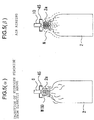
- a step of sterilizing the bottle 2 shown in FIGS. 5 ( ⁇ ) and 5( ⁇ ) is performed between the step of cooling the bottom 2b of the bottle 2 shown in FIG. 2(D) and the step of filling the bottle 2 with the carbonated drink "a" shown in FIG. 2 (E) .
- a mist M or gas G of hydrogen peroxide is blasted to the bottle 2 whose bottom 2b has been cooled and set to an extent that no buckling 2c occurs. More specifically, while the bottle 2 is being conveyed in the upright position with the mouth portion 2a thereof facing up, a spray nozzle 6 arranged at a fixed position injects the mist M or gas G of hydrogen peroxide to the mouth portion 2a of the bottle 2 from directly above the mouth portion 2a. The injected mist M or gas G flows into the bottle 2 or spills from the bottle 2 to flow down along the outer surface of the bottle 2. In this way, a uniform coating of hydrogen peroxide is deposited on the inner and outer surfaces of the bottle 2.
- heated air N is then blasted to the bottle 2.
- an air nozzle 10 arranged at a fixed position injects the heated air N to the mouth portion 2a of the bottle 2 from directly above the mouth portion 2a.
- the injected heated air N flows into the bottle 2 or spills from the bottle 2 to flow down along the outer surface of the bottle 2.
- the hydrogen peroxide deposited on the inner and outer surfaces of the bottle 2 is heated and activated, and the effect of sterilization of the inner and outer surfaces of the bottle 2 is improved.
- an excess of the hydrogen peroxide is discharged from the bottle 2.
- the hydrogen peroxide spray nozzle 6 and the air-rinsing air nozzle 10 are each provided with an umbrella-shaped guide member 45 at a tip end thereof.
- the mist M or gas G of hydrogen peroxide injected from the spray nozzle 6 and the heated air N injected from the air-rinsing air nozzle 10 are guided by the respective guide members 45 to flow along the thread on the outside of the mouth portion 2a of the bottle 2.
- the guide members 45 are provided as required to achieve efficient sterilization of the outer surface of the mouth portion 2a.
- the bottle 2 thus sterilized is filled with the carbonated drink "a” as shown in FIG. 2(E) and sealed with the cap 3 as shown in FIG. 2(F) .
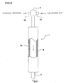
- the mist M or gas G of hydrogen peroxide described above is generated by a mist generator 7 shown in FIG. 6 .
- the mist generator 7 includes a hydrogen peroxide supplying portion 8 that is a twin-fluid spray nozzle that supplies a hydrogen peroxide solution serving as a sterilizer in the form of drops and an evaporating portion 9 that evaporates a spray of hydrogen peroxide supplied from the hydrogen peroxide supplying portion 8 by heating the spray of hydrogen peroxide to a temperature equal to or higher than the boiling point thereof and equal to or lower than the non-degradable temperature thereof.
- the hydrogen peroxide supplying portion 8 is configured to receive the hydrogen peroxide solution and compressed air from a hydrogen peroxide supply path 8a and a compressed air supply path 8b, respectively, and sprays the hydrogen peroxide solution into the evaporating portion 9.
- the evaporating portion 9 is a pipe that incorporates a heater 9a disposed between inner and outer walls thereof, and heats and evaporates the spray of hydrogen peroxide blasted into the pipe.
- the spray nozzle 6 described above is arranged at the end of the evaporating portion 9 opposite to the hydrogen peroxide supplying portion 8.
- the gas of hydrogen peroxide produced by the evaporating portion 9 is injected from the spray nozzle 6 in the form of the mist M or gas G.
- the hydrogen peroxide is uniformly deposited on the inner and outer surfaces of the bottle 2.
- a carbonated drink filling system that performs the carbonated drink filling method according to the second embodiment is configured as shown in FIG. 7 , for example.
- the carbonated drink filling system includes the preform supplying machine 11 (see FIG. 1(A) ) that successively supplies preforms 1 at predetermined intervals, the blow molding machine 12 (see FIGS. 1(B) and 1(C) ) that molds the preforms 1 into the bottles 2, the cooling machine 29 (see FIG. 2(D) ) that forcedly cools the bottoms of the molded bottles 2, a sterilizing machine 30 (see FIGS. 5 ( ⁇ ) and 5( ⁇ )) that sterilizes the cooled bottles 2, and the filling machine 13 (see FIGS. 2(E) and 2(F) ) that fills the sterilized bottles 2 with the carbonated drink "a" and seals the same with the caps 3.
- a train of wheels 31, 32, 33 and 34 is additionally provided between the last wheel 23 in the cooling machine 29 and the wheel 24 in the filler 39.
- the spray nozzle 6 described above is arranged around the wheel 31, and the air nozzle 10 described above is arranged around the wheel 33.
- the mist M or gas G of hydrogen peroxide and the heated air N are supplied to sterilize the bottle 2, and the bottle 2 is then filled with the carbonated drink "a".
- the bottom 2b of the bottle 2 has been cooled and set, so that no buckling 2c occurs on the bottom 2b of the bottle 2 even though the carbonated drink "a" applies pressure to the interior of the bottle 2.
- a step of sterilizing the bottle 2 shown in FIGS. 8 ( ⁇ ) and 8( ⁇ ) and a second step of cooling the bottom 2b of the bottle 2 shown in FIG. 8(D1) are performed between the step of cooling the bottom 2b of the bottle 2 shown in FIG. 2(D) and the step of filling the bottle 2 with the carbonated drink "a" shown in FIG. 2(E) .
- the bottom 2b of the bottle 2 is cooled in two steps before and after the sterilization step, and thus, the degree of cooling in the first cooling step shown in FIG. 2(D) can be lower than the degree of cooling in the cooling step according to the second embodiment. That is, the flow rate of the coolant F used in the first cooling step can be reduced, or the number of coolant injection nozzles 28 installed can be reduced.
- the bottom 2b of the bottle 2 is cooled to an extent that no buckling 2c occurs.
- the sterilization step shown in FIGS. 8 ( ⁇ ) and 8( ⁇ ) is performed on the bottle 2 that has more residual heat than in the second embodiment, the effect of sterilization in the sterilization step is improved.
- the second cooling step is performed as shown in FIG. 8(D1) to further cool the bottom 2b of the bottle 2, so that occurrence of the buckling 2c is completely prevented.
- the first cooling step is performed before sterilization, there is no need to use aseptic air, aseptic water or a chemical agent, and inexpensive means, such as compressed air from a compressor or air from a blower, will suffice.
- aseptic air, aseptic water or a chemical agent needs to be used.
- the sterilized and cooled bottle 2 is filled with the carbonated drink "a” as shown in FIG. 2(E) and then capped as shown in FIG. 2(F) .
- a carbonated drink filling system that performs the carbonated drink filling method according to the third embodiment is configured as shown in FIG. 9 , for example.
- the carbonated drink filling system includes the preform supplying machine 11 (see FIG. 1(A) ) that successively supplies preforms 1 at predetermined intervals, the blow molding machine 12 (see FIGS. 1(B) and 1(C) ) that molds the preforms 1 into the bottles 2, a first-stage cooling machine 29 (see FIG. 2(D) ) that forcedly cools the bottoms 2b of the molded bottles 2, the sterilizing machine 30 (see FIGS. 8 ( ⁇ ) and 8( ⁇ )) that sterilizes the cooled bottles 2, a second-stage cooling machine 44 (see FIG.
- the coolant injection nozzles 28 according to the second embodiment are divided into two groups, and each of the cooling machines 29 and 44 includes one of the groups of coolant injection nozzles 28, for example.
- the mist M or gas G of hydrogen peroxide and the heated air N are supplied to sterilize the bottle 2.
- the bottom 2b of the bottle 2 is cooled to an extent that no buckling 2c occurs on the bottom 2b of the bottle 2, and the bottle 2 is then filled with the carbonated drink "a".
- the step of sterilizing the bottle 2 shown in FIGS. 5 ( ⁇ ) and 5( ⁇ ) is performed between the step of molding the bottle 2 shown in FIG. 1(C) and the step of cooling the bottom 2b of the bottle 2 shown in FIG. 2(D) .
- a mist M or gas G of hydrogen peroxide is blasted to the bottle 2 having just been removed from the molding die 4 as shown in FIG. 5 ( ⁇ ), heated air N is then blasted to the bottle 2 as shown in FIG. 5 ( ⁇ ), and the bottom 2b of the bottle 2 is then forcedly cooled as shown in FIG. 2(D) .
- the step of cooling the bottom 2b of the bottle 2 shown in FIG. 2(D) is performed to cool the bottom 2b of the bottle 2, thereby making the bottom 2b harden so that no buckling 2c occurs.
- the sterilized and cooled bottle 2 is filled with the carbonated drink "a” as shown in FIG. 2(E) and then capped as shown in FIG. 2(F) .
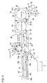
- a carbonated drink filling system that performs the carbonated drink filling method according to the fourth embodiment is configured as shown in FIG. 10 , for example.
- the carbonated drink filling system includes the preform supplying machine 11 (see FIG. 1(A) ) that successively supplies preforms 1 at predetermined intervals, the blow molding machine 12 (see FIGS. 1(B) and 1(C) ) that molds the preforms 1 into the bottles 2, the sterilizing machine 30 (see FIGS. 5 ( ⁇ ) and 5( ⁇ )) that sterilizes the molded bottles 2, a cooling machine 44 (see FIG. 2(D) ) that forcedly cools the bottoms 2b of the sterilized bottles 2, and the filling machine 13 (see FIGS. 2(E) and 2(F) ) that fills the sterilized bottles 2 with the carbonated drink "a" and seals the same with the caps 3.
- the preform supplying machine 11 see FIG. 1(A)
- the blow molding machine 12 see FIGS. 1(B) and 1(C)
- the sterilizing machine 30 see FIGS. 5 ( ⁇ ) and 5( ⁇ )
- a cooling machine 44 see FIG. 2(D)
- the cooling machine 28 is displaced to between the sterilizing machine 30 and the filler 39 and denoted by reference numeral 44.
- the molded bottle 2 is sterilized when the bottle 2 is still hot. After that, the bottom 2b of the bottle 2 is cooled so that no buckling 2c occurs, and the bottle 2 is then filled with the carbonated drink "a".
- the step of sterilizing the bottle 2 shown in FIGS. 5 ( ⁇ ) and 5( ⁇ ) and a water rinsing step shown in FIG. 11 are performed between the step of molding the bottle 2 shown in FIG. 1(C) and the step of cooling the bottom 2b of the bottle 2 shown in FIG. 2(D) .
- a mist M or gas G of hydrogen peroxide is blasted to the bottle 2 having just been removed from the molding die 4 (see FIG. 10 ) as shown in FIG. 5 ( ⁇ ), heated air N is then blasted to the bottle 2 as shown in FIG. 5 ( ⁇ ), the bottle 2 is inverted and rinsed with water by injecting aseptic water Q into the bottle 2 in the inverted positon from a nozzle 47 as shown in FIG. 11 , and the bottom 2b of the bottle 2 restored to the upright position is then forcedly cooled as shown in FIG. 2(D) .
- the heated air N is blasted to the bottle 2, thereby activating the hydrogen peroxide, improving the sterilization effect, and removing an excess of the hydrogen peroxide on the surface of the bottle 2.
- water rinsing of the bottle 2 is performed in the inverted position with the mouth portion 2a facing down, thereby washing the interior of the bottle 2 with the aseptic water Q to remove foreign matters from the interior of the bottle 2.
- the aseptic water Q used for the water rinsing forcedly cools the bottom 2b of the bottle 2 from inside the bottle 2.
- the air rinsing shown in FIG. 5 ( ⁇ ) in the sterilization step may be replaced with the water rinsing and omitted.
- the step of cooling the bottom 2b of the bottle 2 restored to the upright position is performed as shown in FIG. 2(D) .
- the bottom 2b of the bottle 2 is cooled to harden so that no buckling 2c occurs.
- the bottom 2b of the bottle 2 is further cooled by the coolant F injected from the coolant injection nozzles 28, so that occurrence of the buckling 2c on the bottom 2b of the bottle 2 is more effectively prevented.
- the bottle 2 thus sterilized, rinsed with water and cooled is filled with the carbonated drink "a" as shown in FIG. 2(E) and then capped as shown in FIG. 2(F) .
- a carbonated drink filling system that performs the carbonated drink filling method according to the fifth embodiment is configured as shown in FIG. 12 , for example.
- the carbonated drink filling system includes the preform supplying machine 11 (see FIG. 1(A) ) that successively supplies preforms 1 at predetermined intervals, the blow molding machine 12 (see FIGS. 1(B) and 1(C) ) that molds the preforms 1 into the bottles 2, the sterilizing machine 30 (see FIGS. 5 ( ⁇ ) and 5( ⁇ )) that sterilizes the molded bottles 2, a water rinsing machine 46 (see FIG. 11 ) that rinses the bottles 2 with water, the cooling machine 44 (see FIG. 2(D) ) that forcedly cools the bottoms 2b of the bottles 2 rinsed with water, and the filling machine 13 (see FIGS. 2(E) and 2(F) ) that fills the cooled bottles 2 with the carbonated drink "a" and seals the same with the caps 3.
- the preform supplying machine 11 see FIG. 1(A)
- the blow molding machine 12 see FIGS. 1(B) and 1(C)
- the sterilizing machine 30 see FIGS.
- wheels 48 and 49 are added to the carbonated drink filing system according to the fourth embodiment shown in FIG. 10 .
- the molded bottle 2 is sterilized when the bottle 2 is still hot. After that, the bottle 2 is washed, the bottom 2b of the bottle 2 is cooled so that no buckling 2c occurs, and the bottle 2 is then filled with the carbonated drink "a".
- the temperature of the rinsing water can be any temperature that is equal to or lower than the glass transition temperature thereof (specifically, equal to or lower than 75°C).
- the rinsing water desirably comes into contact with at least a central part (gate part) of the bottom of the interior of the bottle.
- the duration of the rinsing is desirably equal to or longer than at least 0.2 seconds.
- the rinsing liquid is not limited to the aseptic water, and any liquid having a sterilization effect, such as peracetic acid, hot water, an alkali solution, acid water, ozone water or chlorine water, has the same cooling effect.
- the level of sterilization of the container can be any level equal to or higher than the required level of sterilization for the content of the bottle, which is the carbonated drink. Thus, in the case of an unsterilized carbonated drink, unsterilized water can also be used.
- the present invention is not limited to the embodiments described above, and various modifications can be made to the embodiments.
- a dry sterilization process using hydrogen peroxide is used to sterilize the bottle in the embodiments described above
- a wet (rinsing) sterilization process using a liquid such as water may be used to sterilize the bottle.
- the bottle may be sterilized by irradiating the bottle with an electron beam or ultraviolet rays.
Landscapes
- Engineering & Computer Science (AREA)
- Mechanical Engineering (AREA)
- Health & Medical Sciences (AREA)
- Manufacturing & Machinery (AREA)
- Epidemiology (AREA)
- Veterinary Medicine (AREA)
- Chemical Kinetics & Catalysis (AREA)
- General Chemical & Material Sciences (AREA)
- Chemical & Material Sciences (AREA)
- Public Health (AREA)
- Life Sciences & Earth Sciences (AREA)
- Animal Behavior & Ethology (AREA)
- General Health & Medical Sciences (AREA)
- Thermal Sciences (AREA)
- Physics & Mathematics (AREA)
- Filling Of Jars Or Cans And Processes For Cleaning And Sealing Jars (AREA)
- Basic Packing Technique (AREA)
- Blow-Moulding Or Thermoforming Of Plastics Or The Like (AREA)
Abstract
Description
- The present invention relates to a carbonated drink filling method and a carbonated drink filling system.
- According to prior art, a preform is continuously transferred and introduced into a heating furnace, heated in the heating furnace to a temperature for molding the preform into a bottle and molded into a bottle in a molding die after the preform exits the heating furnace. The bottle is then sterilized and inverted. Water is then injected into the bottle to wash the interior of the bottle and at the same time is injected to the bottom of the bottle to cool the bottom of the bottle. After that, the bottle is restored to the upright position and then is filled with a carbonated drink. According to this process, even if the bottle has a thick bottom, such as a pressure-resistant bottom, and it takes a long time for heat removal, the bottom of the bottle can be quickly cooled. Thus, even if the bottle is filled with a carbonated drink shortly after the molding of the bottle, the bottom of the bottle is not deformed, and thus the stability of the bottle can be improved (see
Patent Literature 1, for example). - Patent Literature 1:
Japanese Patent Laid-Open No. 2013-237484 - According to the conventional technique described above, the bottle is transferred in the inverted position, and water is injected into the bottle for washing and at the same time is injected to the bottom of the bottle for cooling. Thus, the bottle molded in the upright position needs to be inverted and then restored to the upright position. This leads to an increase in complexity of the structure of the manufacturing line and an increase in equipment cost.
- An object of the present invention is to solve the problem described above.
- To solve the problem described above, the present invention is configured as described below.
- In the description below, to facilitate understanding of the present invention, reference numerals are shown in parentheses. However, the present invention is not limited to the following description.
- That is, the invention defined in
claim 1 adopts a carbonated drink filling method, wherein a preform (1) is continuously transferred and is introduced into a heating furnace (33), the preform (1) is heated to a temperature for molding the preform into a container (2) in the heating furnace (33), the preform (1) is molded into the container (2) in a molding die (4) after the preform (1) exits the heating furnace (33), the container (2) is conveyed in an upright position, a coolant (F) is injected to a bottom (2b) of the container (2) to cool the bottom (2b) of the container (2), the container (2) is filled with a carbonated drink (a) through a mouth portion (2a) of the container (2), and the mouth portion (2a) is then sealed, the coolant (F) being injected in the cooling to the bottom (2b) of the container (2) from a nozzle opening on either or both sides of a conveyance line of the container (2), and the nozzle opening being directed diagonally upward to the bottom (2b) of the container (2) in such a manner that an extension of the nozzle opening intersects with the conveyance line of the container (2). - As recited in
claim 2, in the carbonated drink filling method according toclaim 1, the container (2) may be subjected to a sterilization process before the container (2) is filled with the carbonated drink (a), and the bottom (2b) of the container (a) may be cooled before and/or after the sterilization process. - As recited in claim 3, in the carbonated drink filling method according to
claim 1, the container (2) may be subjected to a sterilization process before the container (2) is filled with the carbonated drink (a), the container (2) is subjected to water rinsing after the sterilization process, and the bottom (2b) of the container (2) may be cooled after the water rinsing. - That is, the invention defined in
claim 4 adopts a carbonated drink filling system, comprising: a transfer device that transfers a preform (1) and a container (2) from where the preform (1) is supplied and molded into the container (2) to where the container (2) is filled with a carbonated drink (a) and sealed; a heating furnace (33) that heats the preform (1) to a molding temperature; a blow molding die (4) that blow-molds the preform (1) into the container (2); a coolant injection nozzle (28) that injects a coolant (F) to a bottom (2b) of the container (2) discharged from the blow molding die (4) in an upright position to cool the bottom (2b) of the container (2); a filler (39) that fills the container (2) with the carbonated drink (a) through a mouth portion (2a) of the container (2); and a capper (40) that seals the mouth portion (2a) of the container (2), the heating furnace (33), the blow molding die (4), the coolant injection nozzle (28), the filler (39) and the capper (40) being arranged in this order from an upstream side to a downstream side along the transfer device, the coolant injection nozzle (28) being provided on either or both sides of a conveyance line of the container (2), and the coolant (F) being injected from a nozzle opening that is directed diagonally upward to the bottom (2b) of the container (2) in such a manner that an extension of the nozzle opening intersects with the conveyance line of the container (2). - As recited in
claim 5, in the carbonated drink filling system according toclaim 4, a sterilization device (30) that performs a sterilization process on the container (2) may be provided upstream of the filler (39), and the coolant injection nozzle (28) may be provided upstream and/or downstream of the sterilization device (30). - As recited in
claim 6, in the carbonated drink filling system according toclaim 4, a sterilization device (30) that performs a sterilization process on the container (2) may be provided upstream of the filler (39), a water rinsing device may be provided downstream of the sterilization device (30), and the coolant injection nozzle (28) may be provided between the water rinsing device and the filler. - According to the carbonated drink filling method according to the present invention, a preform (1) is continuously transferred and is introduced into a heating furnace (33), the preform (1) is heated to a temperature for molding the preform (1) into a container (2) in the heating furnace (33), the preform (1) is molded into the container (2) in a molding die (4) after the preform (1) exits the heating furnace(33), the container (2) is conveyed in an upright position, a coolant (f) is injected to a bottom (2b) of the container (2) to cool the bottom (2b) of the container (2), the container (2) is filled with a carbonated drink (a) through a mouth portion (2a) of the container (2), and the mouth portion (2a) is then sealed, the coolant (F) being injected in the cooling to the bottom (2b) of the container (2) from a nozzle opening on either or both sides of a conveyance line of the container (2), and the nozzle opening being directed diagonally upward to the bottom (2b) of the container (2) in such a manner that an extension of the nozzle opening intersects with the conveyance line of the container (2). Thus, while the container (2) having just been molded is being transferred in the upright position, the bottom (2b) of the container (2) can be quickly cooled to prevent sagging or other deformation thereof, and even if the container (2) is filled with the carbonated drink (a) shortly after the container (2) is molded, outward deformation of the bottom (2b) of the container (2) can be prevented, and the stability of the container (2) can be improved. In addition, unlike the conventional technique, there is no need to invert the container (2) molded in the upright position and then restore the container (2) to the upright position, and the container (2) can be kept in the upright position during transfer thereof, the structure of the manufacturing line of the bottled carbonated drink product can be simplified. In addition, when the bottom (2b) of the container (2) is cooled, the coolant (F) is injected to the bottom (2b) of the container (2) from a nozzle opening on either or both sides of a conveyance line of the container (2), and the nozzle opening is directed diagonally upward to the bottom (2b) of the container (2) in such a manner that an extension of the nozzle opening intersects with the conveyance line of the container (2). Thus, even if the coolant F is a liquid, such as water, droplets of the liquid are less likely to reach the
mouth portion 2a of thebottle 2, so that the possibility that the droplets enter the bottle (2) to contaminate the interior of the bottle (2) is eliminated. -
-
FIG. 1(A) shows a step in the first half of a carbonated drink filling method according to the present invention. -
FIG. 1(B) shows a step in the first half of the carbonated drink filling method according to the present invention. -
FIG. 1(C) shows a step in the first half of the carbonated drink filling method according to the present invention. -
FIG. 2(D) shows a step in the second half of the carbonated drink filling method according to the present invention. -
FIG. 2(E) shows a step in the second half of the carbonated drink filling method according to the present invention. -
FIG. 2(F) shows a step in the second half of the carbonated drink filling method according to the present invention. -
FIG. 3 is a diagram for illustrating a modification of a cooling step. -
FIG. 4 is a schematic plan view of a carbonated drink filing system according to the present invention. -
FIG. 5 is a diagram for illustrating a sterilization step additionally provided in a second embodiment of the present invention. -
FIG. 6 is a partially cut-away view of a hydrogen peroxide mist generator. -
FIG. 7 is a schematic plan view of a carbonated drink filing system according to the second embodiment of the present invention. -
FIG. 8 is a diagram for illustrating a sterilization step and a cooling step additionally provided in a third embodiment of the present invention. -
FIG. 9 is a schematic plan view of a carbonated drink filing system according to a third embodiment of the present invention. -
FIG. 10 is a schematic plan view of a carbonated drink filing system according to a fourth embodiment of the present invention. -
FIG. 11 is a diagram for illustrating a water rinsing step additionally provided in a fifth embodiment of the present invention. -
FIG. 12 is a partially cut-away schematic plan view of a carbonated drink filling system according to the fifth embodiment of the present invention. - In the following, embodiments of the present invention will be described.
- First, a carbonated drink filling method will be described.
- First, a
preform 1 shown inFIG. 1(A) is continuously conveyed at a desired velocity. - The
preform 1 is a bottomed tubular body similar to a test tube that is previously formed from PET (polyethylene terephthalate) by injection molding or the like. Amouth portion 2a similar to that of abottle 2 shown inFIGS. 2(D) to 2(F) is formed on thepreform 1 in an early stage of the molding of thepreform 1. A male thread corresponding to a female thread on a cap 3 is formed on themouth portion 2a during the molding of thepreform 1. - Next, as shown in
FIG. 1(B) , thepreform 1 is heated to a temperature suitable for the subsequent blow molding by aninfrared heater 18a or other heating device. The temperature is approximately between 90°C and 130°C. - The temperature of the
mouth portion 2a of thepreform 1 is maintained to be equal to or lower than 70°C to prevent deformation, for example. - In the heating, as shown in
FIG. 1(B) , thepreform 1 is desirably suspended in an upright position (or inverted position) from a spindle (or mandrel) 43 inserted into themouth portion 2a thereof and is conveyed while rotating with the spindle (or mandrel) 43. Thus, thepreform 1 is uniformly heated by theinfrared heater 18a. - If the mandrel is inserted into the
preform 1 instead of thespindle 43, thepreform 1 can be rotated and conveyed in the inverted position. - As shown in
FIG. 1(C) , theheated preform 1 is blow-molded into thebottle 2 in adie 4. - The die 4, which is a molding die for blow molding, is clamped while being continuously rotated at the same speed as the transfer speed of the
preform 1 and is opened after the blow molding of thepreform 1 in the die 4 is completed. - The
preform 1 excluding themouth portion 2a is uniformly heated to a temperature range suitable for molding in the heating step shown inFIG. 1(B) as described above, and theheated preform 1 is placed in thedie 4, and anextension rod 5 is inserted in thepreform 1 placed in thedie 4 as shown inFIG. 1(C) . - When the
die 4 is being transferred, for example, primary blowing air and secondary blowing air are sequentially blasted into thepreform 1 from an extension rod (not shown) to expand thepreform 1 into thebottle 2 as a final molded product in a cavity C of thedie 4. - Once the
bottle 2 is molded in thedie 4, thedie 4 is opened while being continuously transferred, and thebottle 2 as a finished product is removed from thedie 4 in the upright position. - The bottle just removed from the
die 4 is hot and soft. In particular, a central portion of a bottom 2b of thebottle 2 is the thickest and thus takes some time to cool and set. If thebottle 2 that has not adequately cooled down is filled with a carbonated drink and sealed, a buckling 2c shown by the alternate long and two short dash line inFIGS. 2(E) and 2(F) can occur on the bottom 2b of the bottle. The buckling 2c is a phenomenon in which the bottom 2b of thebottle 2 that is still soft sags down in a protrusion form under a counter pressure applied immediately before filling the bottle with the carbonated drink or the internal pressure of the carbonated drink or the like supplied into the bottle. In particular, if thebottle 2 is to be filled with a drink, such as the carbonated drink, that acts to increase the pressure in thebottle 2 after filling, the bottom 2b of thebottle 2 is made thicker than the other parts to form a petaloid bottom to resist the pressure and thus is less susceptible to cooling and setting, so that the buckling 2c is more likely to occur. If thebottle 2 sets while the buckling 2c is not eliminated, the resultingbottle 2 is unstable and can fall. - To prevent occurrence of the buckling 2c, as shown in
FIG. 2(D) , the bottom 2b of thebottle 2 is forcedly cooled by injecting a coolant F to the bottom 2b of thebottle 2 from outside thebottle 2. - The coolant F may be a gas, such as air, or a liquid, such as water. In the case of a filling machine that produces a product that requires sterilization, aseptic air, aseptic water, or a sterilizer containing a constituent such as peracetic acid, hydrogen peroxide, sodium hypochlorite, ozone water or acid water can be used as the coolant.
- As a device for injecting the coolant F to the bottom 2b of the
bottle 2, acoolant injection nozzle 28 shown inFIG. 2(D) is used. -
Coolant injection nozzles 28 are arranged on the opposite sides of the conveyance line of thebottle 2, and nozzle openings of thecoolant injection nozzle 28 are directed diagonally upward to the bottom 2b of thebottle 2 in such a manner that the extensions of the nozzle openings intersect with the conveyance line of thebottle 2. InFIG. 2(D) , an alternate long andshort dash line 28a indicates the centerline of the nozzle opening. A large number ofcoolant injection nozzles 28 are arranged on the opposite sides of thebottle 2 being conveyed along the direction of conveyance of thebottle 2, as shown inFIG. 4 . For example, the coolant injection nozzles are arranged in two rows in a staggered configuration. To address the difference in size in the lengthwise direction betweenbottles 2, the coolant injection nozzles may also be arranged in a plurality of rows in the vertical direction, as required. - Since the coolant F is injected from the
coolant injection nozzles 28 to the bottom 2b of thebottle 2, the bottom 2b of thebottle 2 conveyed at a high speed is efficiently cooled and quickly sets, and thus, the buckling 2c is prevented from occurring. In addition, since the nozzle openings on the opposite sides of the conveyance line of thebottle 2 are directed diagonally upward to the bottom 2b of thebottle 2 in such a manner that the extensions of the nozzle openings intersect with the conveyance line of thebottle 2, even when the coolant F is a liquid, such as water, droplets of the liquid are less likely to reach themouth portion 2a of thebottle 2, so that the possibility of entry of the droplets to thebottle 2 is eliminated. - When the coolant F is a gas, such as air, as shown in
FIG. 3 , the gas as the coolant F may be injected from the nozzle opening of thecoolant injection nozzle 28 directly opposed to the bottom 2b of thebottle 2. If the coolant F is a gas, the possibility that the coolant F injected from the nozzle opening enters thebottle 2 is low, and if the coolant F is air, the coolant F is harmless even if the coolant F enters thebottle 2. The cooling with a gas can also prevent occurrence of the buckling 2c. - After the bottom 2b of the
bottle 2 has adequately set through the cooling step shown inFIG. 2(D) , thebottle 2 is filled with a carbonated drink "a" from a fillingnozzle 10 as shown inFIG. 2(E) and then capped with a cap 3 serving as a lid as shown inFIG. 2(F) . Thus, occurrence of the buckling 2c on the bottom 2b of thebottle 2 is prevented with reliability. Since no buckling 2c occurs on the bottom 2b of thebottle 2, the bottled carbonated drink "a" product does not tilt or fall and is stored or exhibited in a stable posture, for example. - A carbonated drink filling system that performs the carbonated drink filling method is configured as shown in
FIG. 4 , for example. - As shown in
FIG. 4 , the carbonated drink filling system includes a preform supplying machine 11 (seeFIG. 1(A) ) that successively supplies preforms 1 having the shape of a bottomed tube having themouth portion 2a at predetermined intervals, a blow molding machine 12 (seeFIGS. 1(B) and 1(C) ) that molds thepreforms 1 intobottles 2, a cooling machine 29 (seeFIG. 2(D) ) that forcedly cools thebottoms 2b of the moldedbottles 2, and a filling machine 13 (seeFIGS. 2(E) and 2(F) ) that fills the cooledbottles 2 with the drink "a" and seals the same with the caps 3. - The
blow molding machine 12 and the fillingmachine 13 of the carbonated drink filling system are surrounded bychambers chamber 41a may not be a sealed structure but be a simple frame structure such as a shroud. - Between the
preform supplying machine 11 and the fillingmachine 13, a first conveying path for conveying thepreform 1 or the like, a second conveying path for conveying the die 4 (seeFIG. 1(C) ) having the cavity C having the shape of thefinished bottle 2, and a third conveying path for conveying thebottle 2 or the like molded in thedie 4 are provided. The first to third conveying paths are coupled to each other, and a gripper (not shown) or the like that holds thepreform 1 orbottle 2 during conveyance thereof is provided on these conveying paths. - In the
preform supplying machine 11, the first conveying path includes apreform conveyor 14 that successively supplies thepreforms 1 at predetermined intervals. In addition, the first conveying path is provided with a train ofwheels preforms 1 from a terminal end of thepreform conveyor 14 and anendless chain 18 that receives and conveys thepreform 1. - The
endless chain 18 is arranged as a conveying path for thepreforms 1 in aheating furnace 33 provided with theinfrared heater 18a described above. A large number ofspindles 43 shown inFIG. 1(B) are attached to theendless chain 18 at regular intervals. Eachspindle 43 can rotate on its axis while being transferred as theendless chain 18 travels. Thespindle 43 is inserted into themouth portion 2a of thepreform 1 fed to theendless chain 18 from thewheel 17 as shown inFIG. 1(B) , and thus, thepreform 1 is held in the upright position on thespindle 43. If the mandrel is used instead of thespindle 43, thepreform 1 can be supported and conveyed in the inverted position. - The
heating furnace 33 has a furnace chamber extending in one direction. In the furnace chamber, theendless chain 18 is stretched between a pair ofpulleys endless chain 18 and associated members constitute an endless conveyor that conveys a large number ofpreforms 1 suspended.Infrared heaters 18a are attached to the inner wall surface of the furnace chamber along a going path and a return path of theendless chain 18. - Once the
spindle 43 receives thepreform 1 having been conveyed by thepreform conveyor 14 and the train ofwheels preform 1 is transferred along the inner wall surface of theheating furnace 33 and is heated by theinfrared heaters 18a. While thepreform 1 is being transferred in theheating furnace 33, thepreform 1 rotates on its axis as thespindle 43 rotates and is uniformly heated by theinfrared heaters 18a until the temperature of thepreform 1 excluding themouth portion 2a rises to a temperature between 90°C to 130°C that is suitable for blow molding. Themouth portion 2a is kept at a temperature equal to or lower than 70°C at which no deformation or the like occurs, in order to avoid compromising the sealing of themouth portion 2a with the cap 3. - The
blow molding machine 12 includes a plurality of sets ofdie 4 and extension rod 5 (seeFIG. 1(C) ) that receive thepreforms 1 heated by theinfrared heaters 18a in thepreform supplying machine 11 described above and molds thepreforms 1 into thebottles 2. - The second conveying path that conveys the
preforms 1, the dies 4 and thebottles 2 passes through theblow molding machine 12. The second conveying path includes a train ofwheels - A plurality of dies 4 and a plurality of
extension rods 5 are arranged around thewheel 20 and rotate at a constant speed around thewheel 20 as thewheel 20 rotates. - When the gripper (not shown) on the
wheel 19 having received thepreform 1 heated in theheating furnace 33 of thepreform supplying machine 11 passes thepreform 1 to thedie 4 around thewheel 20, thedie 4, which has been opened in two halves, is closed to hold thepreform 1 as shown inFIG. 1(C) . While thepreform 1 in thedie 4 is rotating around thewheel 20 together with thedie 4 and theextension rod 5, high-pressure air for blow molding is blown from a blow nozzle (not shown) to mold thepreform 1 into thebottle 2. Thepreform 1 is smoothly blow-molded, since thepreform 1 has been uniformly heated to a predetermined temperature in theheating furnace 33 as shown inFIG. 1(B) . - The
preform 1 comes into close contact with the inner surface of the cavity C of thedie 4 and is molded into thebottle 2. When thedie 4 reaches thewheel 21, thedie 4 is opened, and thebottle 2 is received by a gripper (not shown) on thewheel 21. Thebottle 2 is conveyed to around thewheels - The filling
machine 13 has the third conveying path arranged therein, and the third conveying path includes a train ofwheels - A large number of filling
nozzles 10 that fills thebottles 2 with the drink "a" is arranged around thewheel 24 to form afiller 39, and acapper 40 that attaches the cap 3 (seeFIG. 2(F) ) to eachbottle 2 filled with the drink "a" to seal thebottle 2 is formed around thewheel 26. - A train of
wheels blow molding machine 12 and thefiller 39 in the fillingmachine 13, and a large number ofcoolant injection nozzles 28 is arranged on the opposite sides of thebottles 2 conveyed by the train ofwheels coolant injection nozzles 28, the orientation of the nozzle openings and the like are as described above. - The
bottle 2 having exited theblow molding machine 12 is transferred in the upright position between the rows of thecoolant injection nozzles 28, and the coolant F is blasted to the bottom 2b as shown inFIG. 2(D) to cool thebottle 2 to a temperature at which theentire bottle 2 including the bottom 2b is not easily deformed until thebottle 2 reaches thefiller 39 in the fillingmachine 13. - Upon reaching the
filler 39, the cooledbottle 2 is filled with the carbonated drink "a" from the fillingnozzle 10 as shown inFIG. 2(E) , and themouth portion 2a of thebottle 2 is sealed with the cap 3 by thecapper 40. In particular, when thebottle 2 is filled with the carbonated drink, the bottom 2b of thebottle 2 is adequately cooled and has set, no buckling 2c occurs on the bottom 2b of thebottle 2 when themouth portion 2a of thebottle 2 is sealed with the cap 3. - Next, a series of operations of the carbonated drink filling system will be described.
- First, the
preform 1 is conveyed toward theheating furnace 33 by thepreform conveyor 14 and the train ofwheels - The
preform 1 is received by the spindle 43 (seeFIG. 1(B) ) on theendless chain 18 and conveyed into theheating furnace 33. - In the
heating furnace 33, thepreform 1 is uniformly heated by theinfrared heaters 18a until the temperature of thepreform 1 excluding themouth portion 2a reaches a temperature range suitable for blow molding. - The
preform 1 heated to a molding temperature in theheating furnace 33 is held by thedie 4 as shown inFIG. 1(C) and passes by the outer circumference of thewheel 20, and high-pressure air is blasted into thepreform 1 from a blow nozzle (not shown) in the vicinity of theextension rod 5, thereby expanding thepreform 1 in the cavity C to form thebottle 2 as the finished product. - The molded
bottle 2 is removed from thedie 4 by the gripper on thewheel 21 after thedie 4 is opened, and conveyed on the conveying path formed by the train ofwheels - The coolant F, such as water, is injected to the bottom 2b of the
bottle 2 from thecoolant injection nozzles 28 on the opposite sides of thebottle 2 being conveyed by the train ofwheels bottle 2 is intensively cooled and hardens. - In the filling
machine 13, thebottle 2 is filled with the carbonated drink "a" from the fillingnozzle 10 of thefiller 39 as shown inFIG. 2(E) . Although high pressure is applied to the interior of thebottle 2 when thebottle 2 is filled with the carbonated drink "a", thebottle 2 including the bottom 2b, which is the thickest part, has adequately set at this point in time, so that the buckling 2c or other deformation does not occur on the bottom 2b. - The
bottle 2 filled with the drink "a" is sealed with the cap 3 by the capper 40 (seeFIG. 2(F) ) and discharged from an outlet port of thechamber 41b. - According to a second embodiment, a step of sterilizing the
bottle 2 shown inFIGS. 5 (α) and 5(β) is performed between the step of cooling the bottom 2b of thebottle 2 shown inFIG. 2(D) and the step of filling thebottle 2 with the carbonated drink "a" shown inFIG. 2 (E) . - Specifically, as shown in
FIG. 5 (α), a mist M or gas G of hydrogen peroxide is blasted to thebottle 2 whose bottom 2b has been cooled and set to an extent that no buckling 2c occurs. More specifically, while thebottle 2 is being conveyed in the upright position with themouth portion 2a thereof facing up, aspray nozzle 6 arranged at a fixed position injects the mist M or gas G of hydrogen peroxide to themouth portion 2a of thebottle 2 from directly above themouth portion 2a. The injected mist M or gas G flows into thebottle 2 or spills from thebottle 2 to flow down along the outer surface of thebottle 2. In this way, a uniform coating of hydrogen peroxide is deposited on the inner and outer surfaces of thebottle 2. - As shown in
FIG. 5 (β), heated air N is then blasted to thebottle 2. Specifically, while thebottle 2 is being conveyed in the upright position, anair nozzle 10 arranged at a fixed position injects the heated air N to themouth portion 2a of thebottle 2 from directly above themouth portion 2a. The injected heated air N flows into thebottle 2 or spills from thebottle 2 to flow down along the outer surface of thebottle 2. As a result of the supply of the heated air N, the hydrogen peroxide deposited on the inner and outer surfaces of thebottle 2 is heated and activated, and the effect of sterilization of the inner and outer surfaces of thebottle 2 is improved. In addition, an excess of the hydrogen peroxide is discharged from thebottle 2. - As shown in
FIGS. 5 (α) and 5(β), the hydrogenperoxide spray nozzle 6 and the air-rinsingair nozzle 10 are each provided with an umbrella-shapedguide member 45 at a tip end thereof. The mist M or gas G of hydrogen peroxide injected from thespray nozzle 6 and the heated air N injected from the air-rinsingair nozzle 10 are guided by therespective guide members 45 to flow along the thread on the outside of themouth portion 2a of thebottle 2. As a result, the outer surface of thebottle 2 including themouth portion 2a is efficiently sterilized. Theguide members 45 are provided as required to achieve efficient sterilization of the outer surface of themouth portion 2a. - The
bottle 2 thus sterilized is filled with the carbonated drink "a" as shown inFIG. 2(E) and sealed with the cap 3 as shown inFIG. 2(F) . - The mist M or gas G of hydrogen peroxide described above is generated by a mist generator 7 shown in
FIG. 6 . - The mist generator 7 includes a hydrogen
peroxide supplying portion 8 that is a twin-fluid spray nozzle that supplies a hydrogen peroxide solution serving as a sterilizer in the form of drops and an evaporating portion 9 that evaporates a spray of hydrogen peroxide supplied from the hydrogenperoxide supplying portion 8 by heating the spray of hydrogen peroxide to a temperature equal to or higher than the boiling point thereof and equal to or lower than the non-degradable temperature thereof. The hydrogenperoxide supplying portion 8 is configured to receive the hydrogen peroxide solution and compressed air from a hydrogenperoxide supply path 8a and a compressedair supply path 8b, respectively, and sprays the hydrogen peroxide solution into the evaporating portion 9. The evaporating portion 9 is a pipe that incorporates aheater 9a disposed between inner and outer walls thereof, and heats and evaporates the spray of hydrogen peroxide blasted into the pipe. Thespray nozzle 6 described above is arranged at the end of the evaporating portion 9 opposite to the hydrogenperoxide supplying portion 8. The gas of hydrogen peroxide produced by the evaporating portion 9 is injected from thespray nozzle 6 in the form of the mist M or gas G. Thus, the hydrogen peroxide is uniformly deposited on the inner and outer surfaces of thebottle 2. - A carbonated drink filling system that performs the carbonated drink filling method according to the second embodiment is configured as shown in
FIG. 7 , for example. The carbonated drink filling system includes the preform supplying machine 11 (seeFIG. 1(A) ) that successively supplies preforms 1 at predetermined intervals, the blow molding machine 12 (seeFIGS. 1(B) and 1(C) ) that molds thepreforms 1 into thebottles 2, the cooling machine 29 (seeFIG. 2(D) ) that forcedly cools the bottoms of the moldedbottles 2, a sterilizing machine 30 (seeFIGS. 5 (α) and 5(β)) that sterilizes the cooledbottles 2, and the filling machine 13 (seeFIGS. 2(E) and 2(F) ) that fills the sterilizedbottles 2 with the carbonated drink "a" and seals the same with the caps 3. - To provide the sterilizing
machine 30 in the carbonated drink filling system, unlike the first embodiment, a train ofwheels last wheel 23 in the coolingmachine 29 and thewheel 24 in thefiller 39. Thespray nozzle 6 described above is arranged around thewheel 31, and theair nozzle 10 described above is arranged around thewheel 33. - With the carbonated drink filling system, after the bottom 2b of the
bottle 2 is cooled to prevent occurrence of the buckling 2c, the mist M or gas G of hydrogen peroxide and the heated air N are supplied to sterilize thebottle 2, and thebottle 2 is then filled with the carbonated drink "a". At the time when thebottle 2 is filled with the carbonated drink "a", the bottom 2b of thebottle 2 has been cooled and set, so that no buckling 2c occurs on the bottom 2b of thebottle 2 even though the carbonated drink "a" applies pressure to the interior of thebottle 2. - According to a third embodiment, a step of sterilizing the
bottle 2 shown inFIGS. 8 (α) and 8(β) and a second step of cooling the bottom 2b of thebottle 2 shown inFIG. 8(D1) are performed between the step of cooling the bottom 2b of thebottle 2 shown inFIG. 2(D) and the step of filling thebottle 2 with the carbonated drink "a" shown inFIG. 2(E) . - According to the third embodiment, the bottom 2b of the
bottle 2 is cooled in two steps before and after the sterilization step, and thus, the degree of cooling in the first cooling step shown inFIG. 2(D) can be lower than the degree of cooling in the cooling step according to the second embodiment. That is, the flow rate of the coolant F used in the first cooling step can be reduced, or the number ofcoolant injection nozzles 28 installed can be reduced. - In this case also, the bottom 2b of the
bottle 2 is cooled to an extent that no buckling 2c occurs. In addition, since the sterilization step shown inFIGS. 8 (α) and 8(β) is performed on thebottle 2 that has more residual heat than in the second embodiment, the effect of sterilization in the sterilization step is improved. - After the sterilization step, the second cooling step is performed as shown in
FIG. 8(D1) to further cool the bottom 2b of thebottle 2, so that occurrence of the buckling 2c is completely prevented. - Furthermore, since the first cooling step is performed before sterilization, there is no need to use aseptic air, aseptic water or a chemical agent, and inexpensive means, such as compressed air from a compressor or air from a blower, will suffice. However, in the second cooling step, aseptic air, aseptic water or a chemical agent needs to be used.
- The sterilized and cooled
bottle 2 is filled with the carbonated drink "a" as shown inFIG. 2(E) and then capped as shown inFIG. 2(F) . - A carbonated drink filling system that performs the carbonated drink filling method according to the third embodiment is configured as shown in
FIG. 9 , for example. The carbonated drink filling system includes the preform supplying machine 11 (seeFIG. 1(A) ) that successively supplies preforms 1 at predetermined intervals, the blow molding machine 12 (seeFIGS. 1(B) and 1(C) ) that molds thepreforms 1 into thebottles 2, a first-stage cooling machine 29 (seeFIG. 2(D) ) that forcedly cools thebottoms 2b of the moldedbottles 2, the sterilizing machine 30 (seeFIGS. 8 (α) and 8(β)) that sterilizes the cooledbottles 2, a second-stage cooling machine 44 (seeFIG. 8(D1) ) that forcedly further cools thebottoms 2b of the sterilizedbottles 2, and the filling machine 13 (seeFIGS. 2(E) and 2(F) ) that fills the sterilized and cooledbottles 2 with the drink "a" and seals the same with the caps 3. - To provide the first-
stage cooling machine 29 and the second-stage cooling machine 44 in the carbonated drink filling system, unlike the second embodiment, thecoolant injection nozzles 28 according to the second embodiment are divided into two groups, and each of thecooling machines coolant injection nozzles 28, for example. - With the carbonated drink filling system, after the bottom 2b of the
bottle 2 is cooled to some extent, the mist M or gas G of hydrogen peroxide and the heated air N are supplied to sterilize thebottle 2. After that, the bottom 2b of thebottle 2 is cooled to an extent that no buckling 2c occurs on the bottom 2b of thebottle 2, and thebottle 2 is then filled with the carbonated drink "a". - According to a fourth embodiment, the step of sterilizing the
bottle 2 shown inFIGS. 5 (α) and 5(β) is performed between the step of molding thebottle 2 shown inFIG. 1(C) and the step of cooling the bottom 2b of thebottle 2 shown inFIG. 2(D) . - Specifically, a mist M or gas G of hydrogen peroxide is blasted to the
bottle 2 having just been removed from the molding die 4 as shown inFIG. 5 (α), heated air N is then blasted to thebottle 2 as shown inFIG. 5 (β), and the bottom 2b of thebottle 2 is then forcedly cooled as shown inFIG. 2(D) . - Most of the heat applied to the
preform 1 remains in thebottle 2 having just been removed from the molding die 4, and the residual heat activates the hydrogen peroxide and improves the sterilization effect. - After the sterilization process of the
bottle 2, the step of cooling the bottom 2b of thebottle 2 shown inFIG. 2(D) is performed to cool the bottom 2b of thebottle 2, thereby making the bottom 2b harden so that no buckling 2c occurs. - The sterilized and cooled
bottle 2 is filled with the carbonated drink "a" as shown inFIG. 2(E) and then capped as shown inFIG. 2(F) . - A carbonated drink filling system that performs the carbonated drink filling method according to the fourth embodiment is configured as shown in
FIG. 10 , for example. - Specifically, the carbonated drink filling system includes the preform supplying machine 11 (see
FIG. 1(A) ) that successively supplies preforms 1 at predetermined intervals, the blow molding machine 12 (seeFIGS. 1(B) and 1(C) ) that molds thepreforms 1 into thebottles 2, the sterilizing machine 30 (seeFIGS. 5 (α) and 5(β)) that sterilizes the moldedbottles 2, a cooling machine 44 (seeFIG. 2(D) ) that forcedly cools thebottoms 2b of the sterilizedbottles 2, and the filling machine 13 (seeFIGS. 2(E) and 2(F) ) that fills the sterilizedbottles 2 with the carbonated drink "a" and seals the same with the caps 3. - Unlike the second embodiment, the cooling
machine 28 is displaced to between the sterilizingmachine 30 and thefiller 39 and denoted byreference numeral 44. - With the carbonated drink filling system, the molded
bottle 2 is sterilized when thebottle 2 is still hot. After that, the bottom 2b of thebottle 2 is cooled so that no buckling 2c occurs, and thebottle 2 is then filled with the carbonated drink "a". - According to a fifth embodiment, the step of sterilizing the
bottle 2 shown inFIGS. 5 (α) and 5(β) and a water rinsing step shown inFIG. 11 are performed between the step of molding thebottle 2 shown inFIG. 1(C) and the step of cooling the bottom 2b of thebottle 2 shown inFIG. 2(D) . - Specifically, a mist M or gas G of hydrogen peroxide is blasted to the
bottle 2 having just been removed from the molding die 4 (seeFIG. 10 ) as shown inFIG. 5 (α), heated air N is then blasted to thebottle 2 as shown inFIG. 5 (β), thebottle 2 is inverted and rinsed with water by injecting aseptic water Q into thebottle 2 in the inverted positon from anozzle 47 as shown inFIG. 11 , and the bottom 2b of thebottle 2 restored to the upright position is then forcedly cooled as shown inFIG. 2(D) . - Most of the heat applied to the
preform 1 remains in thebottle 2 having just been removed from the molding die 4, and the residual heat activates the hydrogen peroxide deposited on thebottle 2 and improves the sterilization effect. - After the sterilization process of the
bottle 2, the heated air N is blasted to thebottle 2, thereby activating the hydrogen peroxide, improving the sterilization effect, and removing an excess of the hydrogen peroxide on the surface of thebottle 2. After that, water rinsing of thebottle 2 is performed in the inverted position with themouth portion 2a facing down, thereby washing the interior of thebottle 2 with the aseptic water Q to remove foreign matters from the interior of thebottle 2. The aseptic water Q used for the water rinsing forcedly cools the bottom 2b of thebottle 2 from inside thebottle 2. - The air rinsing shown in
FIG. 5 (β) in the sterilization step may be replaced with the water rinsing and omitted. - After the water rinsing of the
bottle 2, the step of cooling the bottom 2b of thebottle 2 restored to the upright position is performed as shown inFIG. 2(D) . Thus, the bottom 2b of thebottle 2 is cooled to harden so that no buckling 2c occurs. In addition to being cooled by the water rinsing, the bottom 2b of thebottle 2 is further cooled by the coolant F injected from thecoolant injection nozzles 28, so that occurrence of the buckling 2c on the bottom 2b of thebottle 2 is more effectively prevented. - The
bottle 2 thus sterilized, rinsed with water and cooled is filled with the carbonated drink "a" as shown inFIG. 2(E) and then capped as shown inFIG. 2(F) . - A carbonated drink filling system that performs the carbonated drink filling method according to the fifth embodiment is configured as shown in
FIG. 12 , for example. - Specifically, the carbonated drink filling system includes the preform supplying machine 11 (see
FIG. 1(A) ) that successively supplies preforms 1 at predetermined intervals, the blow molding machine 12 (seeFIGS. 1(B) and 1(C) ) that molds thepreforms 1 into thebottles 2, the sterilizing machine 30 (seeFIGS. 5 (α) and 5(β)) that sterilizes the moldedbottles 2, a water rinsing machine 46 (seeFIG. 11 ) that rinses thebottles 2 with water, the cooling machine 44 (seeFIG. 2(D) ) that forcedly cools thebottoms 2b of thebottles 2 rinsed with water, and the filling machine 13 (seeFIGS. 2(E) and 2(F) ) that fills the cooledbottles 2 with the carbonated drink "a" and seals the same with the caps 3. - As shown in
FIG. 12 , since thewater rinsing machine 46 is additionally provided,wheels FIG. 10 . - With the carbonated drink filling system, the molded
bottle 2 is sterilized when thebottle 2 is still hot. After that, thebottle 2 is washed, the bottom 2b of thebottle 2 is cooled so that no buckling 2c occurs, and thebottle 2 is then filled with the carbonated drink "a". - When the bottle is made of PET, the temperature of the rinsing water can be any temperature that is equal to or lower than the glass transition temperature thereof (specifically, equal to or lower than 75°C). The rinsing water desirably comes into contact with at least a central part (gate part) of the bottom of the interior of the bottle. The duration of the rinsing is desirably equal to or longer than at least 0.2 seconds. As far as the temperature of the rinsing liquid is equal to or lower than 75°C, the rinsing liquid is not limited to the aseptic water, and any liquid having a sterilization effect, such as peracetic acid, hot water, an alkali solution, acid water, ozone water or chlorine water, has the same cooling effect. The level of sterilization of the container can be any level equal to or higher than the required level of sterilization for the content of the bottle, which is the carbonated drink. Thus, in the case of an unsterilized carbonated drink, unsterilized water can also be used.
- The present invention is not limited to the embodiments described above, and various modifications can be made to the embodiments. For example, although a dry sterilization process using hydrogen peroxide is used to sterilize the bottle in the embodiments described above, a wet (rinsing) sterilization process using a liquid such as water may be used to sterilize the bottle. Alternatively, the bottle may be sterilized by irradiating the bottle with an electron beam or ultraviolet rays.
-
- 1
- preform
- 2
- bottle
- 2a
- mouth portion of bottle
- 2b
- bottom of bottle
- 4
- molding die
- 28
- coolant injection nozzle
- 30
- sterilizing machine
- 33
- heating furnace
- 39
- filler
- 40
- capper
- F
- coolant
- a
- carbonated drink
Claims (6)
- A carbonated drink filling method, wherein a preform is continuously transferred and is introduced into a heating furnace, the preform is heated to a temperature for molding the preform into a container in the heating furnace, the preform is molded into the container in a molding die after the preform exits the heating furnace, the container is conveyed in an upright position, a coolant is injected to a bottom of the container to cool the bottom of the container, the container is filled with a carbonated drink through a mouth portion of the container, and the mouth portion is then sealed, the coolant being injected in the cooling to the bottom of the container from a nozzle opening on either or both sides of a conveyance line of the container, and the nozzle opening being directed diagonally upward to the bottom of the container in such a manner that an extension of the nozzle opening intersects with the conveyance line of the container.
- The carbonated drink filling method according to claim 1, wherein the container is subjected to a sterilization process before the container is filled with the carbonated drink, and the bottom of the container is cooled before and/or after the sterilization process.
- The carbonated drink filling method according to claim 1, wherein the container is subjected to a sterilization process before the container is filled with the carbonated drink, the container is subjected to water rinsing after the sterilization process, and the bottom of the container is cooled after the water rinsing.
- A carbonated drink filling system, comprising: a transfer device that transfers a preform and a container from where the preform is supplied and molded into the container to where the container is filled with a carbonated drink and sealed; a heating furnace that heats the preform to a molding temperature; a blow molding die that blow-molds the preform into the container; a coolant injection nozzle that injects a coolant to a bottom of the container discharged from the blow molding die in an upright position to cool the bottom of the container; a filler that fills the container with the carbonated drink through a mouth portion of the container; and a capper that seals the mouth portion of the container, the heating furnace, the blow molding die, the coolant injection nozzle, the filler and the capper being arranged in this order from an upstream side to a downstream side along the transfer device, the coolant injection nozzle being provided on either or both sides of a conveyance line of the container, and the coolant being injected from a nozzle opening that is directed diagonally upward to the bottom of the container in such a manner that an extension of the nozzle opening intersects with the conveyance line of the container.
- The carbonated drink filling system according to claim 4, wherein a sterilization device that performs a sterilization process on the container is provided upstream of the filler, and the coolant injection nozzle is provided upstream and/or downstream of the sterilization device.
- The carbonated drink filling system according to claim 4, wherein a sterilization device that performs a sterilization process on the container is provided upstream of the filler, a water rinsing device is provided downstream of the sterilization device, and the coolant injection nozzle is provided between the water rinsing device and the filler.
Applications Claiming Priority (2)
| Application Number | Priority Date | Filing Date | Title |
|---|---|---|---|
| JP2014194747 | 2014-09-25 | ||
| PCT/JP2015/076726 WO2016047609A1 (en) | 2014-09-25 | 2015-09-18 | Carbonated beverage filling method and device |
Publications (3)
| Publication Number | Publication Date |
|---|---|
| EP3199489A1 true EP3199489A1 (en) | 2017-08-02 |
| EP3199489A4 EP3199489A4 (en) | 2018-06-20 |
| EP3199489B1 EP3199489B1 (en) | 2023-11-01 |
Family
ID=55581136
Family Applications (1)
| Application Number | Title | Priority Date | Filing Date |
|---|---|---|---|
| EP15844366.3A Active EP3199489B1 (en) | 2014-09-25 | 2015-09-18 | Carbonated beverage filling method and device |
Country Status (5)
| Country | Link |
|---|---|
| US (1) | US10906793B2 (en) |
| EP (1) | EP3199489B1 (en) |
| JP (1) | JP6627767B2 (en) |
| CN (1) | CN106715321B (en) |
| WO (1) | WO2016047609A1 (en) |
Cited By (1)
| Publication number | Priority date | Publication date | Assignee | Title |
|---|---|---|---|---|
| WO2017102280A3 (en) * | 2015-12-14 | 2018-01-04 | Khs Gmbh | Method and device for the plasma processing of containers |
Families Citing this family (3)
| Publication number | Priority date | Publication date | Assignee | Title |
|---|---|---|---|---|
| DE102017007443A1 (en) * | 2017-08-05 | 2019-02-07 | Kocher-Plastik Maschinenbau Gmbh | Blow molding, filling and closing method and then produced container product, in particular ampoule product |
| FR3084845B1 (en) * | 2018-08-09 | 2020-07-17 | Sidel Participations | PREFORM HANDLING DEVICE HAVING HEIGHT ADJUSTABLE COOLING DEVICE |
| CN113212867B (en) * | 2021-05-13 | 2023-02-10 | 山西国润制药有限公司 | Inhale first device of filling with acetylcysteine solution |
Family Cites Families (21)
| Publication number | Priority date | Publication date | Assignee | Title |
|---|---|---|---|---|
| US3512996A (en) * | 1966-06-27 | 1970-05-19 | Owens Illinois Inc | Packaging milk |
| FR2616774B1 (en) * | 1987-06-19 | 1989-10-20 | Air Liquide | METHOD FOR MANUFACTURING GLASS OBJECTS COMPRISING A COOLING STAGE |
| US6171541B1 (en) * | 1998-03-31 | 2001-01-09 | Husky Injection Molding Systems Ltd. | Preform post-mold cooling method and apparatus |
| US6485670B1 (en) * | 1999-11-09 | 2002-11-26 | Schmalbach-Lubeca Ag | Blow molding method for producing pasteurizable containers |
| US7632089B2 (en) * | 2004-05-07 | 2009-12-15 | Graham Packaging Pet Technologies, Inc. | Take out and cooling system and method |
| FR2871093B1 (en) * | 2004-06-08 | 2007-11-16 | Sidel Sas | PROCESS AND INSTALLATION FOR MANUFACTURING CONTAINERS WITH COOLING AFTER FORMING |
| US7887319B2 (en) * | 2005-10-11 | 2011-02-15 | Toyo Seikan Kaisha, Ltd. | Apparatus for cooling preformed articles and method of cooling preformed articles |
| JP5739101B2 (en) * | 2007-09-03 | 2015-06-24 | 大日本印刷株式会社 | Packaging manufacturing equipment |
| CN103625699B (en) * | 2008-05-20 | 2016-05-11 | 大日本印刷株式会社 | Beverage fill method and device |
| DE102008048812A1 (en) * | 2008-09-24 | 2010-04-01 | Khs Ag | Method and device for the combined production and filling of plastic containers |
| FR2939708B1 (en) * | 2008-12-17 | 2011-01-14 | Sidel Participations | PROCESS AND INSTALLATION FOR APPLYING A FLUID TO THERMOPLASTIC CONTAINER FOUNTS, IN PARTICULAR FOR COOLING HOT FOUNDATIONS OF MOLDING THERMOPLASTIC CONTAINERS |
| JP5784275B2 (en) * | 2009-02-06 | 2015-09-24 | 大日本印刷株式会社 | Beverage filling method and apparatus |
| DE102009060655A1 (en) * | 2009-12-22 | 2011-06-30 | Krones Ag, 93073 | Cooling device for stabilizing a container structure |
| US8650908B2 (en) * | 2010-05-25 | 2014-02-18 | Emhart Glass S.A. | Post-manufacture glass container thermal strengthening on a conveyor |
| JP5847077B2 (en) | 2010-05-25 | 2016-01-20 | 大塚製薬株式会社 | Aseptic filling system |
| DE102010042165A1 (en) * | 2010-10-07 | 2012-04-12 | Krones Aktiengesellschaft | Process for treating at least one container in a container treatment plant |
| JP6015110B2 (en) * | 2012-05-09 | 2016-10-26 | 大日本印刷株式会社 | Beverage filling method and apparatus |
| JP6004161B2 (en) * | 2012-05-17 | 2016-10-05 | サントリーホールディングス株式会社 | Container processing equipment |
| DE102012108329A1 (en) * | 2012-09-07 | 2014-05-28 | Krones Ag | Apparatus and method for producing beverage containers |
| DE102013101407A1 (en) * | 2013-02-13 | 2014-08-14 | Khs Gmbh | Process for packaging liquid products under pressure in bottles of plastic or similar containers |
| DE102013109907A1 (en) * | 2013-09-10 | 2015-03-12 | Krones Ag | Device for ground aftercooling |
-
2015
- 2015-09-18 CN CN201580049383.4A patent/CN106715321B/en active Active
- 2015-09-18 JP JP2016550310A patent/JP6627767B2/en active Active
- 2015-09-18 WO PCT/JP2015/076726 patent/WO2016047609A1/en not_active Ceased
- 2015-09-18 US US15/512,688 patent/US10906793B2/en active Active
- 2015-09-18 EP EP15844366.3A patent/EP3199489B1/en active Active
Cited By (2)
| Publication number | Priority date | Publication date | Assignee | Title |
|---|---|---|---|---|
| WO2017102280A3 (en) * | 2015-12-14 | 2018-01-04 | Khs Gmbh | Method and device for the plasma processing of containers |
| US11660361B2 (en) | 2015-12-14 | 2023-05-30 | Khs Gmbh | Method and device for the plasma processing of containers |
Also Published As
| Publication number | Publication date |
|---|---|
| JP6627767B2 (en) | 2020-01-08 |
| US10906793B2 (en) | 2021-02-02 |
| CN106715321B (en) | 2020-06-09 |
| EP3199489A4 (en) | 2018-06-20 |
| WO2016047609A1 (en) | 2016-03-31 |
| EP3199489B1 (en) | 2023-11-01 |
| US20170297884A1 (en) | 2017-10-19 |
| JPWO2016047609A1 (en) | 2017-07-06 |
| CN106715321A (en) | 2017-05-24 |
Similar Documents
| Publication | Publication Date | Title |
|---|---|---|
| CN103732501B (en) | Beverage filling method and device thereof | |
| EP3070010B1 (en) | Preform sterilization method | |
| EP3109030B1 (en) | Blow molding machine and method for sterilizing same | |
| EP3827964B1 (en) | Aseptic blow molding machine and aseptic blow molding method | |
| US20160257054A1 (en) | Method and apparatus for sterilizing bottle | |
| EP3118129B1 (en) | Method and apparatus for the sterilisation of containers | |
| US11655133B2 (en) | Cap sterilizer, content filling system, cap sterilization method, and content filling method | |
| CN115103804B (en) | Aseptic filling method and aseptic filling machine | |
| EP3199489B1 (en) | Carbonated beverage filling method and device | |
| JP7567895B2 (en) | Aseptic filling method and aseptic filling machine | |
| EP3292986B1 (en) | Aseptic container molding method and apparatus and aseptic filling method and apparatus | |
| EP3643474B1 (en) | Preform heating device and preform heating method | |
| JP6291765B2 (en) | Bottle sterilization method | |
| CN105939936A (en) | Container sterilization method and device | |
| JP6015110B2 (en) | Beverage filling method and apparatus | |
| US12617140B2 (en) | Apparatus and method for forming plastic preforms into plastic containers with clean room | |
| JP5804164B2 (en) | Aseptic filling method and apparatus | |
| JP2022135777A (en) | Aseptic filling method and aseptic filling device | |
| JP2022135778A (en) | Aseptic filling method and aseptic filling device | |
| JP2015024659A (en) | Aseptic filling apparatus |
Legal Events
| Date | Code | Title | Description |
|---|---|---|---|
| STAA | Information on the status of an ep patent application or granted ep patent |
Free format text: STATUS: THE INTERNATIONAL PUBLICATION HAS BEEN MADE |
|
| PUAI | Public reference made under article 153(3) epc to a published international application that has entered the european phase |
Free format text: ORIGINAL CODE: 0009012 |
|
| STAA | Information on the status of an ep patent application or granted ep patent |
Free format text: STATUS: REQUEST FOR EXAMINATION WAS MADE |
|
| 17P | Request for examination filed |
Effective date: 20170406 |
|
| AK | Designated contracting states |
Kind code of ref document: A1 Designated state(s): AL AT BE BG CH CY CZ DE DK EE ES FI FR GB GR HR HU IE IS IT LI LT LU LV MC MK MT NL NO PL PT RO RS SE SI SK SM TR |
|
| AX | Request for extension of the european patent |
Extension state: BA ME |
|
| DAV | Request for validation of the european patent (deleted) | ||
| DAX | Request for extension of the european patent (deleted) | ||
| A4 | Supplementary search report drawn up and despatched |
Effective date: 20180518 |
|
| RIC1 | Information provided on ipc code assigned before grant |
Ipc: B67C 7/00 20060101AFI20180511BHEP Ipc: B08B 9/32 20060101ALI20180511BHEP |
|
| STAA | Information on the status of an ep patent application or granted ep patent |
Free format text: STATUS: EXAMINATION IS IN PROGRESS |
|
| 17Q | First examination report despatched |
Effective date: 20211223 |
|
| REG | Reference to a national code |
Ref country code: DE Ref legal event code: R079 Free format text: PREVIOUS MAIN CLASS: B67C0007000000 Ipc: B08B0009320000 Ref country code: DE Ref legal event code: R079 Ref document number: 602015086387 Country of ref document: DE Free format text: PREVIOUS MAIN CLASS: B67C0007000000 Ipc: B08B0009320000 |
|
| GRAP | Despatch of communication of intention to grant a patent |
Free format text: ORIGINAL CODE: EPIDOSNIGR1 |
|
| RIC1 | Information provided on ipc code assigned before grant |
Ipc: B67C 3/22 20060101ALI20230426BHEP Ipc: A61L 2/22 20060101ALI20230426BHEP Ipc: A61L 2/20 20060101ALI20230426BHEP Ipc: B08B 9/28 20060101ALI20230426BHEP Ipc: B08B 9/32 20060101AFI20230426BHEP |
|
| STAA | Information on the status of an ep patent application or granted ep patent |
Free format text: STATUS: GRANT OF PATENT IS INTENDED |
|
| RIC1 | Information provided on ipc code assigned before grant |
Ipc: B67C 7/00 20060101ALI20230509BHEP Ipc: A61L 2/22 20060101ALI20230509BHEP Ipc: A61L 2/20 20060101ALI20230509BHEP Ipc: B08B 9/28 20060101ALI20230509BHEP Ipc: B08B 9/32 20060101AFI20230509BHEP |
|
| INTG | Intention to grant announced |
Effective date: 20230601 |
|
| GRAS | Grant fee paid |
Free format text: ORIGINAL CODE: EPIDOSNIGR3 |
|
| GRAA | (expected) grant |
Free format text: ORIGINAL CODE: 0009210 |
|
| STAA | Information on the status of an ep patent application or granted ep patent |
Free format text: STATUS: THE PATENT HAS BEEN GRANTED |
|
| AK | Designated contracting states |
Kind code of ref document: B1 Designated state(s): AL AT BE BG CH CY CZ DE DK EE ES FI FR GB GR HR HU IE IS IT LI LT LU LV MC MK MT NL NO PL PT RO RS SE SI SK SM TR |
|
| REG | Reference to a national code |
Ref country code: GB Ref legal event code: FG4D |
|
| REG | Reference to a national code |
Ref country code: CH Ref legal event code: EP |
|
| REG | Reference to a national code |
Ref country code: DE Ref legal event code: R096 Ref document number: 602015086387 Country of ref document: DE |
|
| REG | Reference to a national code |
Ref country code: IE Ref legal event code: FG4D |
|
| REG | Reference to a national code |
Ref country code: LT Ref legal event code: MG9D |
|
| REG | Reference to a national code |
Ref country code: NL Ref legal event code: MP Effective date: 20231101 |
|
| PG25 | Lapsed in a contracting state [announced via postgrant information from national office to epo] |
Ref country code: GR Free format text: LAPSE BECAUSE OF FAILURE TO SUBMIT A TRANSLATION OF THE DESCRIPTION OR TO PAY THE FEE WITHIN THE PRESCRIBED TIME-LIMIT Effective date: 20240202 |
|
| PG25 | Lapsed in a contracting state [announced via postgrant information from national office to epo] |
Ref country code: IS Free format text: LAPSE BECAUSE OF FAILURE TO SUBMIT A TRANSLATION OF THE DESCRIPTION OR TO PAY THE FEE WITHIN THE PRESCRIBED TIME-LIMIT Effective date: 20240301 |
|
| PG25 | Lapsed in a contracting state [announced via postgrant information from national office to epo] |
Ref country code: LT Free format text: LAPSE BECAUSE OF FAILURE TO SUBMIT A TRANSLATION OF THE DESCRIPTION OR TO PAY THE FEE WITHIN THE PRESCRIBED TIME-LIMIT Effective date: 20231101 |
|
| REG | Reference to a national code |
Ref country code: AT Ref legal event code: MK05 Ref document number: 1626612 Country of ref document: AT Kind code of ref document: T Effective date: 20231101 |
|
| PG25 | Lapsed in a contracting state [announced via postgrant information from national office to epo] |
Ref country code: NL Free format text: LAPSE BECAUSE OF FAILURE TO SUBMIT A TRANSLATION OF THE DESCRIPTION OR TO PAY THE FEE WITHIN THE PRESCRIBED TIME-LIMIT Effective date: 20231101 |
|
| PG25 | Lapsed in a contracting state [announced via postgrant information from national office to epo] |
Ref country code: AT Free format text: LAPSE BECAUSE OF FAILURE TO SUBMIT A TRANSLATION OF THE DESCRIPTION OR TO PAY THE FEE WITHIN THE PRESCRIBED TIME-LIMIT Effective date: 20231101 |
|
| PG25 | Lapsed in a contracting state [announced via postgrant information from national office to epo] |
Ref country code: ES Free format text: LAPSE BECAUSE OF FAILURE TO SUBMIT A TRANSLATION OF THE DESCRIPTION OR TO PAY THE FEE WITHIN THE PRESCRIBED TIME-LIMIT Effective date: 20231101 |
|
| PG25 | Lapsed in a contracting state [announced via postgrant information from national office to epo] |
Ref country code: NL Free format text: LAPSE BECAUSE OF FAILURE TO SUBMIT A TRANSLATION OF THE DESCRIPTION OR TO PAY THE FEE WITHIN THE PRESCRIBED TIME-LIMIT Effective date: 20231101 Ref country code: LT Free format text: LAPSE BECAUSE OF FAILURE TO SUBMIT A TRANSLATION OF THE DESCRIPTION OR TO PAY THE FEE WITHIN THE PRESCRIBED TIME-LIMIT Effective date: 20231101 Ref country code: IS Free format text: LAPSE BECAUSE OF FAILURE TO SUBMIT A TRANSLATION OF THE DESCRIPTION OR TO PAY THE FEE WITHIN THE PRESCRIBED TIME-LIMIT Effective date: 20240301 Ref country code: GR Free format text: LAPSE BECAUSE OF FAILURE TO SUBMIT A TRANSLATION OF THE DESCRIPTION OR TO PAY THE FEE WITHIN THE PRESCRIBED TIME-LIMIT Effective date: 20240202 Ref country code: ES Free format text: LAPSE BECAUSE OF FAILURE TO SUBMIT A TRANSLATION OF THE DESCRIPTION OR TO PAY THE FEE WITHIN THE PRESCRIBED TIME-LIMIT Effective date: 20231101 Ref country code: BG Free format text: LAPSE BECAUSE OF FAILURE TO SUBMIT A TRANSLATION OF THE DESCRIPTION OR TO PAY THE FEE WITHIN THE PRESCRIBED TIME-LIMIT Effective date: 20240201 Ref country code: AT Free format text: LAPSE BECAUSE OF FAILURE TO SUBMIT A TRANSLATION OF THE DESCRIPTION OR TO PAY THE FEE WITHIN THE PRESCRIBED TIME-LIMIT Effective date: 20231101 Ref country code: PT Free format text: LAPSE BECAUSE OF FAILURE TO SUBMIT A TRANSLATION OF THE DESCRIPTION OR TO PAY THE FEE WITHIN THE PRESCRIBED TIME-LIMIT Effective date: 20240301 |
|
| PG25 | Lapsed in a contracting state [announced via postgrant information from national office to epo] |
Ref country code: SE Free format text: LAPSE BECAUSE OF FAILURE TO SUBMIT A TRANSLATION OF THE DESCRIPTION OR TO PAY THE FEE WITHIN THE PRESCRIBED TIME-LIMIT Effective date: 20231101 Ref country code: RS Free format text: LAPSE BECAUSE OF FAILURE TO SUBMIT A TRANSLATION OF THE DESCRIPTION OR TO PAY THE FEE WITHIN THE PRESCRIBED TIME-LIMIT Effective date: 20231101 Ref country code: PL Free format text: LAPSE BECAUSE OF FAILURE TO SUBMIT A TRANSLATION OF THE DESCRIPTION OR TO PAY THE FEE WITHIN THE PRESCRIBED TIME-LIMIT Effective date: 20231101 Ref country code: NO Free format text: LAPSE BECAUSE OF FAILURE TO SUBMIT A TRANSLATION OF THE DESCRIPTION OR TO PAY THE FEE WITHIN THE PRESCRIBED TIME-LIMIT Effective date: 20240201 Ref country code: LV Free format text: LAPSE BECAUSE OF FAILURE TO SUBMIT A TRANSLATION OF THE DESCRIPTION OR TO PAY THE FEE WITHIN THE PRESCRIBED TIME-LIMIT Effective date: 20231101 Ref country code: HR Free format text: LAPSE BECAUSE OF FAILURE TO SUBMIT A TRANSLATION OF THE DESCRIPTION OR TO PAY THE FEE WITHIN THE PRESCRIBED TIME-LIMIT Effective date: 20231101 |
|
| PG25 | Lapsed in a contracting state [announced via postgrant information from national office to epo] |
Ref country code: DK Free format text: LAPSE BECAUSE OF FAILURE TO SUBMIT A TRANSLATION OF THE DESCRIPTION OR TO PAY THE FEE WITHIN THE PRESCRIBED TIME-LIMIT Effective date: 20231101 |
|
| PG25 | Lapsed in a contracting state [announced via postgrant information from national office to epo] |
Ref country code: CZ Free format text: LAPSE BECAUSE OF FAILURE TO SUBMIT A TRANSLATION OF THE DESCRIPTION OR TO PAY THE FEE WITHIN THE PRESCRIBED TIME-LIMIT Effective date: 20231101 |
|
| PG25 | Lapsed in a contracting state [announced via postgrant information from national office to epo] |
Ref country code: SK Free format text: LAPSE BECAUSE OF FAILURE TO SUBMIT A TRANSLATION OF THE DESCRIPTION OR TO PAY THE FEE WITHIN THE PRESCRIBED TIME-LIMIT Effective date: 20231101 |
|
| PG25 | Lapsed in a contracting state [announced via postgrant information from national office to epo] |
Ref country code: SM Free format text: LAPSE BECAUSE OF FAILURE TO SUBMIT A TRANSLATION OF THE DESCRIPTION OR TO PAY THE FEE WITHIN THE PRESCRIBED TIME-LIMIT Effective date: 20231101 Ref country code: SK Free format text: LAPSE BECAUSE OF FAILURE TO SUBMIT A TRANSLATION OF THE DESCRIPTION OR TO PAY THE FEE WITHIN THE PRESCRIBED TIME-LIMIT Effective date: 20231101 Ref country code: RO Free format text: LAPSE BECAUSE OF FAILURE TO SUBMIT A TRANSLATION OF THE DESCRIPTION OR TO PAY THE FEE WITHIN THE PRESCRIBED TIME-LIMIT Effective date: 20231101 Ref country code: EE Free format text: LAPSE BECAUSE OF FAILURE TO SUBMIT A TRANSLATION OF THE DESCRIPTION OR TO PAY THE FEE WITHIN THE PRESCRIBED TIME-LIMIT Effective date: 20231101 Ref country code: DK Free format text: LAPSE BECAUSE OF FAILURE TO SUBMIT A TRANSLATION OF THE DESCRIPTION OR TO PAY THE FEE WITHIN THE PRESCRIBED TIME-LIMIT Effective date: 20231101 Ref country code: CZ Free format text: LAPSE BECAUSE OF FAILURE TO SUBMIT A TRANSLATION OF THE DESCRIPTION OR TO PAY THE FEE WITHIN THE PRESCRIBED TIME-LIMIT Effective date: 20231101 |
|
| REG | Reference to a national code |
Ref country code: DE Ref legal event code: R097 Ref document number: 602015086387 Country of ref document: DE |
|
| PLBE | No opposition filed within time limit |
Free format text: ORIGINAL CODE: 0009261 |
|
| STAA | Information on the status of an ep patent application or granted ep patent |
Free format text: STATUS: NO OPPOSITION FILED WITHIN TIME LIMIT |
|
| 26N | No opposition filed |
Effective date: 20240802 |
|
| PG25 | Lapsed in a contracting state [announced via postgrant information from national office to epo] |
Ref country code: SI Free format text: LAPSE BECAUSE OF FAILURE TO SUBMIT A TRANSLATION OF THE DESCRIPTION OR TO PAY THE FEE WITHIN THE PRESCRIBED TIME-LIMIT Effective date: 20231101 |
|
| PG25 | Lapsed in a contracting state [announced via postgrant information from national office to epo] |
Ref country code: SI Free format text: LAPSE BECAUSE OF FAILURE TO SUBMIT A TRANSLATION OF THE DESCRIPTION OR TO PAY THE FEE WITHIN THE PRESCRIBED TIME-LIMIT Effective date: 20231101 |
|
| PG25 | Lapsed in a contracting state [announced via postgrant information from national office to epo] |
Ref country code: MC Free format text: LAPSE BECAUSE OF FAILURE TO SUBMIT A TRANSLATION OF THE DESCRIPTION OR TO PAY THE FEE WITHIN THE PRESCRIBED TIME-LIMIT Effective date: 20231101 |
|
| REG | Reference to a national code |
Ref country code: CH Ref legal event code: PL |
|
| PG25 | Lapsed in a contracting state [announced via postgrant information from national office to epo] |
Ref country code: LU Free format text: LAPSE BECAUSE OF NON-PAYMENT OF DUE FEES Effective date: 20240918 |
|
| GBPC | Gb: european patent ceased through non-payment of renewal fee |
Effective date: 20240918 |
|
| PG25 | Lapsed in a contracting state [announced via postgrant information from national office to epo] |
Ref country code: GB Free format text: LAPSE BECAUSE OF NON-PAYMENT OF DUE FEES Effective date: 20240918 |
|
| REG | Reference to a national code |
Ref country code: BE Ref legal event code: MM Effective date: 20240930 |
|
| PG25 | Lapsed in a contracting state [announced via postgrant information from national office to epo] |
Ref country code: BE Free format text: LAPSE BECAUSE OF NON-PAYMENT OF DUE FEES Effective date: 20240930 |
|
| PG25 | Lapsed in a contracting state [announced via postgrant information from national office to epo] |
Ref country code: CH Free format text: LAPSE BECAUSE OF NON-PAYMENT OF DUE FEES Effective date: 20240930 |
|
| PG25 | Lapsed in a contracting state [announced via postgrant information from national office to epo] |
Ref country code: IE Free format text: LAPSE BECAUSE OF NON-PAYMENT OF DUE FEES Effective date: 20240918 |
|
| PG25 | Lapsed in a contracting state [announced via postgrant information from national office to epo] |
Ref country code: FI Free format text: LAPSE BECAUSE OF FAILURE TO SUBMIT A TRANSLATION OF THE DESCRIPTION OR TO PAY THE FEE WITHIN THE PRESCRIBED TIME-LIMIT Effective date: 20231101 |
|
| PGFP | Annual fee paid to national office [announced via postgrant information from national office to epo] |
Ref country code: DE Payment date: 20250919 Year of fee payment: 11 |
|
| PGFP | Annual fee paid to national office [announced via postgrant information from national office to epo] |
Ref country code: IT Payment date: 20250923 Year of fee payment: 11 |
|
| PGFP | Annual fee paid to national office [announced via postgrant information from national office to epo] |
Ref country code: FR Payment date: 20250922 Year of fee payment: 11 |
|
| PG25 | Lapsed in a contracting state [announced via postgrant information from national office to epo] |
Ref country code: CY Free format text: LAPSE BECAUSE OF FAILURE TO SUBMIT A TRANSLATION OF THE DESCRIPTION OR TO PAY THE FEE WITHIN THE PRESCRIBED TIME-LIMIT; INVALID AB INITIO Effective date: 20150918 |
|
| PG25 | Lapsed in a contracting state [announced via postgrant information from national office to epo] |
Ref country code: HU Free format text: LAPSE BECAUSE OF FAILURE TO SUBMIT A TRANSLATION OF THE DESCRIPTION OR TO PAY THE FEE WITHIN THE PRESCRIBED TIME-LIMIT; INVALID AB INITIO Effective date: 20150918 |
|
| PG25 | Lapsed in a contracting state [announced via postgrant information from national office to epo] |
Ref country code: TR Free format text: LAPSE BECAUSE OF FAILURE TO SUBMIT A TRANSLATION OF THE DESCRIPTION OR TO PAY THE FEE WITHIN THE PRESCRIBED TIME-LIMIT Effective date: 20231101 |