EP3199446A1 - Method for reducing natural evaporation rate of lng storage tank - Google Patents
Method for reducing natural evaporation rate of lng storage tank Download PDFInfo
- Publication number
- EP3199446A1 EP3199446A1 EP15845368.8A EP15845368A EP3199446A1 EP 3199446 A1 EP3199446 A1 EP 3199446A1 EP 15845368 A EP15845368 A EP 15845368A EP 3199446 A1 EP3199446 A1 EP 3199446A1
- Authority
- EP
- European Patent Office
- Prior art keywords
- vacuum
- insulating layer
- heat
- hose
- storage tank
- Prior art date
- Legal status (The legal status is an assumption and is not a legal conclusion. Google has not performed a legal analysis and makes no representation as to the accuracy of the status listed.)
- Withdrawn
Links
Images


Classifications
-
- F—MECHANICAL ENGINEERING; LIGHTING; HEATING; WEAPONS; BLASTING
- F17—STORING OR DISTRIBUTING GASES OR LIQUIDS
- F17C—VESSELS FOR CONTAINING OR STORING COMPRESSED, LIQUEFIED OR SOLIDIFIED GASES; FIXED-CAPACITY GAS-HOLDERS; FILLING VESSELS WITH, OR DISCHARGING FROM VESSELS, COMPRESSED, LIQUEFIED, OR SOLIDIFIED GASES
- F17C1/00—Pressure vessels, e.g. gas cylinder, gas tank, replaceable cartridge
- F17C1/12—Pressure vessels, e.g. gas cylinder, gas tank, replaceable cartridge with provision for thermal insulation
-
- B—PERFORMING OPERATIONS; TRANSPORTING
- B63—SHIPS OR OTHER WATERBORNE VESSELS; RELATED EQUIPMENT
- B63B—SHIPS OR OTHER WATERBORNE VESSELS; EQUIPMENT FOR SHIPPING
- B63B25/00—Load-accommodating arrangements, e.g. stowing, trimming; Vessels characterised thereby
- B63B25/02—Load-accommodating arrangements, e.g. stowing, trimming; Vessels characterised thereby for bulk goods
- B63B25/08—Load-accommodating arrangements, e.g. stowing, trimming; Vessels characterised thereby for bulk goods fluid
- B63B25/12—Load-accommodating arrangements, e.g. stowing, trimming; Vessels characterised thereby for bulk goods fluid closed
- B63B25/16—Load-accommodating arrangements, e.g. stowing, trimming; Vessels characterised thereby for bulk goods fluid closed heat-insulated
-
- B—PERFORMING OPERATIONS; TRANSPORTING
- B65—CONVEYING; PACKING; STORING; HANDLING THIN OR FILAMENTARY MATERIAL
- B65D—CONTAINERS FOR STORAGE OR TRANSPORT OF ARTICLES OR MATERIALS, e.g. BAGS, BARRELS, BOTTLES, BOXES, CANS, CARTONS, CRATES, DRUMS, JARS, TANKS, HOPPERS, FORWARDING CONTAINERS; ACCESSORIES, CLOSURES, OR FITTINGS THEREFOR; PACKAGING ELEMENTS; PACKAGES
- B65D90/00—Component parts, details or accessories for large containers
- B65D90/02—Wall construction
- B65D90/06—Coverings, e.g. for insulating purposes
-
- F—MECHANICAL ENGINEERING; LIGHTING; HEATING; WEAPONS; BLASTING
- F17—STORING OR DISTRIBUTING GASES OR LIQUIDS
- F17C—VESSELS FOR CONTAINING OR STORING COMPRESSED, LIQUEFIED OR SOLIDIFIED GASES; FIXED-CAPACITY GAS-HOLDERS; FILLING VESSELS WITH, OR DISCHARGING FROM VESSELS, COMPRESSED, LIQUEFIED, OR SOLIDIFIED GASES
- F17C13/00—Details of vessels or of the filling or discharging of vessels
-
- F—MECHANICAL ENGINEERING; LIGHTING; HEATING; WEAPONS; BLASTING
- F17—STORING OR DISTRIBUTING GASES OR LIQUIDS
- F17C—VESSELS FOR CONTAINING OR STORING COMPRESSED, LIQUEFIED OR SOLIDIFIED GASES; FIXED-CAPACITY GAS-HOLDERS; FILLING VESSELS WITH, OR DISCHARGING FROM VESSELS, COMPRESSED, LIQUEFIED, OR SOLIDIFIED GASES
- F17C13/00—Details of vessels or of the filling or discharging of vessels
- F17C13/001—Thermal insulation specially adapted for cryogenic vessels
-
- F—MECHANICAL ENGINEERING; LIGHTING; HEATING; WEAPONS; BLASTING
- F17—STORING OR DISTRIBUTING GASES OR LIQUIDS
- F17C—VESSELS FOR CONTAINING OR STORING COMPRESSED, LIQUEFIED OR SOLIDIFIED GASES; FIXED-CAPACITY GAS-HOLDERS; FILLING VESSELS WITH, OR DISCHARGING FROM VESSELS, COMPRESSED, LIQUEFIED, OR SOLIDIFIED GASES
- F17C2201/00—Vessel construction, in particular geometry, arrangement or size
- F17C2201/05—Size
- F17C2201/052—Size large (>1000 m3)
-
- F—MECHANICAL ENGINEERING; LIGHTING; HEATING; WEAPONS; BLASTING
- F17—STORING OR DISTRIBUTING GASES OR LIQUIDS
- F17C—VESSELS FOR CONTAINING OR STORING COMPRESSED, LIQUEFIED OR SOLIDIFIED GASES; FIXED-CAPACITY GAS-HOLDERS; FILLING VESSELS WITH, OR DISCHARGING FROM VESSELS, COMPRESSED, LIQUEFIED, OR SOLIDIFIED GASES
- F17C2203/00—Vessel construction, in particular walls or details thereof
- F17C2203/03—Thermal insulations
- F17C2203/0304—Thermal insulations by solid means
- F17C2203/0358—Thermal insulations by solid means in form of panels
-
- F—MECHANICAL ENGINEERING; LIGHTING; HEATING; WEAPONS; BLASTING
- F17—STORING OR DISTRIBUTING GASES OR LIQUIDS
- F17C—VESSELS FOR CONTAINING OR STORING COMPRESSED, LIQUEFIED OR SOLIDIFIED GASES; FIXED-CAPACITY GAS-HOLDERS; FILLING VESSELS WITH, OR DISCHARGING FROM VESSELS, COMPRESSED, LIQUEFIED, OR SOLIDIFIED GASES
- F17C2203/00—Vessel construction, in particular walls or details thereof
- F17C2203/03—Thermal insulations
- F17C2203/0375—Thermal insulations by gas
- F17C2203/0379—Inert
-
- F—MECHANICAL ENGINEERING; LIGHTING; HEATING; WEAPONS; BLASTING
- F17—STORING OR DISTRIBUTING GASES OR LIQUIDS
- F17C—VESSELS FOR CONTAINING OR STORING COMPRESSED, LIQUEFIED OR SOLIDIFIED GASES; FIXED-CAPACITY GAS-HOLDERS; FILLING VESSELS WITH, OR DISCHARGING FROM VESSELS, COMPRESSED, LIQUEFIED, OR SOLIDIFIED GASES
- F17C2203/00—Vessel construction, in particular walls or details thereof
- F17C2203/03—Thermal insulations
- F17C2203/0391—Thermal insulations by vacuum
-
- F—MECHANICAL ENGINEERING; LIGHTING; HEATING; WEAPONS; BLASTING
- F17—STORING OR DISTRIBUTING GASES OR LIQUIDS
- F17C—VESSELS FOR CONTAINING OR STORING COMPRESSED, LIQUEFIED OR SOLIDIFIED GASES; FIXED-CAPACITY GAS-HOLDERS; FILLING VESSELS WITH, OR DISCHARGING FROM VESSELS, COMPRESSED, LIQUEFIED, OR SOLIDIFIED GASES
- F17C2203/00—Vessel construction, in particular walls or details thereof
- F17C2203/06—Materials for walls or layers thereof; Properties or structures of walls or their materials
- F17C2203/0602—Wall structures; Special features thereof
- F17C2203/0612—Wall structures
- F17C2203/0626—Multiple walls
- F17C2203/0629—Two walls
-
- F—MECHANICAL ENGINEERING; LIGHTING; HEATING; WEAPONS; BLASTING
- F17—STORING OR DISTRIBUTING GASES OR LIQUIDS
- F17C—VESSELS FOR CONTAINING OR STORING COMPRESSED, LIQUEFIED OR SOLIDIFIED GASES; FIXED-CAPACITY GAS-HOLDERS; FILLING VESSELS WITH, OR DISCHARGING FROM VESSELS, COMPRESSED, LIQUEFIED, OR SOLIDIFIED GASES
- F17C2203/00—Vessel construction, in particular walls or details thereof
- F17C2203/06—Materials for walls or layers thereof; Properties or structures of walls or their materials
- F17C2203/0602—Wall structures; Special features thereof
- F17C2203/0612—Wall structures
- F17C2203/0626—Multiple walls
- F17C2203/0631—Three or more walls
-
- F—MECHANICAL ENGINEERING; LIGHTING; HEATING; WEAPONS; BLASTING
- F17—STORING OR DISTRIBUTING GASES OR LIQUIDS
- F17C—VESSELS FOR CONTAINING OR STORING COMPRESSED, LIQUEFIED OR SOLIDIFIED GASES; FIXED-CAPACITY GAS-HOLDERS; FILLING VESSELS WITH, OR DISCHARGING FROM VESSELS, COMPRESSED, LIQUEFIED, OR SOLIDIFIED GASES
- F17C2203/00—Vessel construction, in particular walls or details thereof
- F17C2203/06—Materials for walls or layers thereof; Properties or structures of walls or their materials
- F17C2203/068—Special properties of materials for vessel walls
- F17C2203/0682—Special properties of materials for vessel walls with liquid or gas layer
-
- F—MECHANICAL ENGINEERING; LIGHTING; HEATING; WEAPONS; BLASTING
- F17—STORING OR DISTRIBUTING GASES OR LIQUIDS
- F17C—VESSELS FOR CONTAINING OR STORING COMPRESSED, LIQUEFIED OR SOLIDIFIED GASES; FIXED-CAPACITY GAS-HOLDERS; FILLING VESSELS WITH, OR DISCHARGING FROM VESSELS, COMPRESSED, LIQUEFIED, OR SOLIDIFIED GASES
- F17C2205/00—Vessel construction, in particular mounting arrangements, attachments or identifications means
- F17C2205/03—Fluid connections, filters, valves, closure means or other attachments
- F17C2205/0302—Fittings, valves, filters, or components in connection with the gas storage device
- F17C2205/0341—Filters
-
- F—MECHANICAL ENGINEERING; LIGHTING; HEATING; WEAPONS; BLASTING
- F17—STORING OR DISTRIBUTING GASES OR LIQUIDS
- F17C—VESSELS FOR CONTAINING OR STORING COMPRESSED, LIQUEFIED OR SOLIDIFIED GASES; FIXED-CAPACITY GAS-HOLDERS; FILLING VESSELS WITH, OR DISCHARGING FROM VESSELS, COMPRESSED, LIQUEFIED, OR SOLIDIFIED GASES
- F17C2221/00—Handled fluid, in particular type of fluid
- F17C2221/03—Mixtures
- F17C2221/032—Hydrocarbons
- F17C2221/033—Methane, e.g. natural gas, CNG, LNG, GNL, GNC, PLNG
-
- F—MECHANICAL ENGINEERING; LIGHTING; HEATING; WEAPONS; BLASTING
- F17—STORING OR DISTRIBUTING GASES OR LIQUIDS
- F17C—VESSELS FOR CONTAINING OR STORING COMPRESSED, LIQUEFIED OR SOLIDIFIED GASES; FIXED-CAPACITY GAS-HOLDERS; FILLING VESSELS WITH, OR DISCHARGING FROM VESSELS, COMPRESSED, LIQUEFIED, OR SOLIDIFIED GASES
- F17C2223/00—Handled fluid before transfer, i.e. state of fluid when stored in the vessel or before transfer from the vessel
- F17C2223/01—Handled fluid before transfer, i.e. state of fluid when stored in the vessel or before transfer from the vessel characterised by the phase
- F17C2223/0107—Single phase
- F17C2223/013—Single phase liquid
-
- F—MECHANICAL ENGINEERING; LIGHTING; HEATING; WEAPONS; BLASTING
- F17—STORING OR DISTRIBUTING GASES OR LIQUIDS
- F17C—VESSELS FOR CONTAINING OR STORING COMPRESSED, LIQUEFIED OR SOLIDIFIED GASES; FIXED-CAPACITY GAS-HOLDERS; FILLING VESSELS WITH, OR DISCHARGING FROM VESSELS, COMPRESSED, LIQUEFIED, OR SOLIDIFIED GASES
- F17C2223/00—Handled fluid before transfer, i.e. state of fluid when stored in the vessel or before transfer from the vessel
- F17C2223/01—Handled fluid before transfer, i.e. state of fluid when stored in the vessel or before transfer from the vessel characterised by the phase
- F17C2223/0146—Two-phase
- F17C2223/0153—Liquefied gas, e.g. LPG, GPL
- F17C2223/0161—Liquefied gas, e.g. LPG, GPL cryogenic, e.g. LNG, GNL, PLNG
-
- F—MECHANICAL ENGINEERING; LIGHTING; HEATING; WEAPONS; BLASTING
- F17—STORING OR DISTRIBUTING GASES OR LIQUIDS
- F17C—VESSELS FOR CONTAINING OR STORING COMPRESSED, LIQUEFIED OR SOLIDIFIED GASES; FIXED-CAPACITY GAS-HOLDERS; FILLING VESSELS WITH, OR DISCHARGING FROM VESSELS, COMPRESSED, LIQUEFIED, OR SOLIDIFIED GASES
- F17C2223/00—Handled fluid before transfer, i.e. state of fluid when stored in the vessel or before transfer from the vessel
- F17C2223/03—Handled fluid before transfer, i.e. state of fluid when stored in the vessel or before transfer from the vessel characterised by the pressure level
- F17C2223/033—Small pressure, e.g. for liquefied gas
-
- F—MECHANICAL ENGINEERING; LIGHTING; HEATING; WEAPONS; BLASTING
- F17—STORING OR DISTRIBUTING GASES OR LIQUIDS
- F17C—VESSELS FOR CONTAINING OR STORING COMPRESSED, LIQUEFIED OR SOLIDIFIED GASES; FIXED-CAPACITY GAS-HOLDERS; FILLING VESSELS WITH, OR DISCHARGING FROM VESSELS, COMPRESSED, LIQUEFIED, OR SOLIDIFIED GASES
- F17C2250/00—Accessories; Control means; Indicating, measuring or monitoring of parameters
- F17C2250/06—Controlling or regulating of parameters as output values
- F17C2250/0605—Parameters
- F17C2250/0626—Pressure
-
- F—MECHANICAL ENGINEERING; LIGHTING; HEATING; WEAPONS; BLASTING
- F17—STORING OR DISTRIBUTING GASES OR LIQUIDS
- F17C—VESSELS FOR CONTAINING OR STORING COMPRESSED, LIQUEFIED OR SOLIDIFIED GASES; FIXED-CAPACITY GAS-HOLDERS; FILLING VESSELS WITH, OR DISCHARGING FROM VESSELS, COMPRESSED, LIQUEFIED, OR SOLIDIFIED GASES
- F17C2250/00—Accessories; Control means; Indicating, measuring or monitoring of parameters
- F17C2250/06—Controlling or regulating of parameters as output values
- F17C2250/0605—Parameters
- F17C2250/0631—Temperature
-
- F—MECHANICAL ENGINEERING; LIGHTING; HEATING; WEAPONS; BLASTING
- F17—STORING OR DISTRIBUTING GASES OR LIQUIDS
- F17C—VESSELS FOR CONTAINING OR STORING COMPRESSED, LIQUEFIED OR SOLIDIFIED GASES; FIXED-CAPACITY GAS-HOLDERS; FILLING VESSELS WITH, OR DISCHARGING FROM VESSELS, COMPRESSED, LIQUEFIED, OR SOLIDIFIED GASES
- F17C2250/00—Accessories; Control means; Indicating, measuring or monitoring of parameters
- F17C2250/06—Controlling or regulating of parameters as output values
- F17C2250/0605—Parameters
- F17C2250/0642—Composition; Humidity
-
- F—MECHANICAL ENGINEERING; LIGHTING; HEATING; WEAPONS; BLASTING
- F17—STORING OR DISTRIBUTING GASES OR LIQUIDS
- F17C—VESSELS FOR CONTAINING OR STORING COMPRESSED, LIQUEFIED OR SOLIDIFIED GASES; FIXED-CAPACITY GAS-HOLDERS; FILLING VESSELS WITH, OR DISCHARGING FROM VESSELS, COMPRESSED, LIQUEFIED, OR SOLIDIFIED GASES
- F17C2260/00—Purposes of gas storage and gas handling
- F17C2260/03—Dealing with losses
- F17C2260/031—Dealing with losses due to heat transfer
- F17C2260/033—Dealing with losses due to heat transfer by enhancing insulation
-
- F—MECHANICAL ENGINEERING; LIGHTING; HEATING; WEAPONS; BLASTING
- F17—STORING OR DISTRIBUTING GASES OR LIQUIDS
- F17C—VESSELS FOR CONTAINING OR STORING COMPRESSED, LIQUEFIED OR SOLIDIFIED GASES; FIXED-CAPACITY GAS-HOLDERS; FILLING VESSELS WITH, OR DISCHARGING FROM VESSELS, COMPRESSED, LIQUEFIED, OR SOLIDIFIED GASES
- F17C2265/00—Effects achieved by gas storage or gas handling
- F17C2265/03—Treating the boil-off
-
- F—MECHANICAL ENGINEERING; LIGHTING; HEATING; WEAPONS; BLASTING
- F17—STORING OR DISTRIBUTING GASES OR LIQUIDS
- F17C—VESSELS FOR CONTAINING OR STORING COMPRESSED, LIQUEFIED OR SOLIDIFIED GASES; FIXED-CAPACITY GAS-HOLDERS; FILLING VESSELS WITH, OR DISCHARGING FROM VESSELS, COMPRESSED, LIQUEFIED, OR SOLIDIFIED GASES
- F17C2270/00—Applications
- F17C2270/01—Applications for fluid transport or storage
- F17C2270/0102—Applications for fluid transport or storage on or in the water
- F17C2270/0105—Ships
-
- F—MECHANICAL ENGINEERING; LIGHTING; HEATING; WEAPONS; BLASTING
- F17—STORING OR DISTRIBUTING GASES OR LIQUIDS
- F17C—VESSELS FOR CONTAINING OR STORING COMPRESSED, LIQUEFIED OR SOLIDIFIED GASES; FIXED-CAPACITY GAS-HOLDERS; FILLING VESSELS WITH, OR DISCHARGING FROM VESSELS, COMPRESSED, LIQUEFIED, OR SOLIDIFIED GASES
- F17C2270/00—Applications
- F17C2270/01—Applications for fluid transport or storage
- F17C2270/0102—Applications for fluid transport or storage on or in the water
- F17C2270/0105—Ships
- F17C2270/0107—Wall panels
Definitions
- the present invention relates to a method for reducing the boil-off rate of an LNG storage tank and, more particularly, to a method for reducing the boil-off rate of LNG stored in an LNG storage tank by improving insulation performance of the LNG storage tank.
- LNG is obtained by cooling natural gas to an extremely low temperature (about -163°C) and is suitable for long-distance transportation by sea since LNG is significantly reduced in volume, as compared with natural gas in a gaseous state.
- LNG carriers are designed to carry liquefied gas to an onshore source of demand and, for this purpose, include a storage tank capable of withstanding ultra-low temperatures of LNG.
- Such a storage tank is divided into an independent tank-type and a membrane-type depending on whether the weight of cargo is directly applied to an insulator.
- the membrane-type storage tank is divided into a GTT NO 96-type and a Mark III-type
- the independent tank-type storage tank is divided into a MOSS-type and an IHI-SPB-type.
- the GTT NO 96-type and GTT Mark III-type were formerly called a GT type and a TGZ type.
- GT Gas Transport
- TGZ Technigaz
- the GT type and the TGZ type have been referred to as the GTT NO 96-type and the GTT Mark III-type, respectively.
- Plywood is widely used as a material for an insulating box or an insulating panel. Plywood is evaluated as the most competitive material among materials that can function as a load bearing structural material, as an insulator for preventing heat penetration from the outside, and as a container for storing other materials.
- plywood has a water content of about 10% to 15%. As the water content decreases, the thermal conductivity of the plywood is reduced. When the thermal conductivity of the plywood is reduced, the thermal conductivity of the insulation box or the insulation panel is also reduced, thereby causing increase in insulation performance of the storage tank.
- Plywood used in typical LNG storage tanks has a water content of 10% to 15%, and has a higher thermal conductivity than an insulation box or an insulation panel including the plywood.
- the plywood used in typical LNG storage tanks contributes to deterioration in insulation performance of the insulation box or the insulation panel and thus increase in boil-off rate (BOR) of LNG stored in the storage tank.
- Embodiments of the present invention have been conceived to solve such a problem in the art and provide a method for reducing the boil-off rate of an LNG storage tank, which includes operating a vacuum pump to reduce an internal pressure of a heat-insulating layer of the LNG storage tank.
- a method for reducing a boil-off rate of an LNG storage tank includes: fabricating an LNG storage tank including a primary heat-insulating layer and a secondary heat-insulating layer; connecting one end of a second vacuum hose to the secondary heat-insulating layer; connecting the other end of the second vacuum hose to a vacuum pump; and operating the vacuum pump to reduce the internal pressure of the secondary heat-insulating layer, wherein an inner side of the secondary heat-insulating layer is evacuated to a vacuum to reduce the water content of plywood contained in the secondary heat-insulating layer.
- the method may further include: connecting one end of a first vacuum hose to the primary heat-insulating layer of the LNG storage tank; connecting the other end of the first vacuum hose to the vacuum pump; and operating the vacuum pump to reduce the internal pressure of the primary heat-insulating layer, wherein the inside of the primary heat-insulating layer may be evacuated to a vacuum to reduce the water content of plywood contained in the primary heat-insulating layer, and the internal pressure of the primary heat-insulating layer may be maintained to be higher than the internal pressure of the secondary heat-insulating layer during performing the method for reducing the boil-off rate of the LNG storage tank.
- the vacuum pump may include a plurality of vacuum pumps, each of which may be connected to the other end of the first vacuum hose and the other end of the second vacuum hose.
- the first vacuum hose and the second vacuum hose may include the same number of first vacuum hoses as the vacuum pumps and the same number of second vacuum hoses as the vacuum pumps, respectively, such that the other ends of the first vacuum hoses and the other ends of the second vacuum hoses are connected to the vacuum pumps in a one-to-one manner.
- One end of the first vacuum hose may be connected to the primary heat-insulating layer; one end of the second vacuum hose may be connected to the secondary heat-insulating layer; the other end of the first vacuum hose may be branched off into the same number of portions as the vacuum pumps to be connected to the respective vacuum pumps; and the other end of the second vacuum hose may be branched off into the same number of portions as the vacuum pumps to be connected to the respective vacuum pumps.
- the other end of the first vacuum hose may be connected to a first vacuum pump and the other end of the second vacuum hose may be connected to a second vacuum pump.
- the first vacuum pump and the second vacuum pump may include a plurality of first vacuum pumps and a plurality of second vacuum pumps, respectively, wherein each of the first vacuum pumps may be connected to the other end of the first vacuum hose and each of the second vacuum pumps may be connected to the other end of the second vacuum hose.
- the first vacuum hose may include the same number of first vacuum hoses as the first vacuum pumps such that the other ends of the first vacuum hoses are connected to the first vacuum pumps in a one-to-one manner
- the second vacuum hose may include the same number of second vacuum hoses as the second vacuum pumps such that the other ends of the second vacuum hoses are connected to the second vacuum pumps in a one-to-one manner.
- One end of the first vacuum hose may be connected to the primary heat-insulating layer; one end of the second vacuum hose may be connected to the secondary heat-insulating layer; the other end of the first vacuum hose may be branched off into the same number of portions as the first vacuum pumps to be connected to the respective first vacuum pumps; and the other end of the second vacuum hose may be branched off into the same number of portions as the second vacuum pumps to be connected to the respective second vacuum pumps.
- the water content of plywood may be controlled by adjusting a period of time for which internal pressures of the primary heat-insulating layer and the secondary heat-insulating layer are maintained constant.
- the method may further include: supplying a gas having a temperature higher than or equal to room temperature to the primary heat-insulating layer when the temperature of plywood contained in the primary heat-insulating layer drops below zero, and supplying a gas having a temperature higher than or equal to room temperature to the secondary heat-insulating layer when the temperature of plywood contained in the secondary heat-insulating layer drops below zero.
- the gas may include any one of argon, helium, and nitrogen.
- At least one of the primary heat-insulating layer and the secondary heat-insulating layer may be maintained under vacuum after the water content of the plywood is reduced.
- the method may further include supplying a gas to at least one of the primary heat-insulating layer and the secondary heat-insulating layer after the water content of the plywood is reduced.
- the gas may include any one of argon, helium, and nitrogen.
- a method for reducing a boil-off rate of an LNG storage tank includes: fabricating an LNG storage tank comprising a heat-insulating layer; connecting one end of a vacuum hose to the heat-insulating layer; connecting the other end of the vacuum hose to a vacuum pump; and operating the vacuum pump to reduce the internal pressure of the heat-insulating layer, wherein the inside of the heat-insulating layer is evacuated to a vacuum to reduce the water content of plywood contained in the heat-insulating layer.
- a vacuum apparatus includes: a vacuum hose having one end connected to a heat-insulating layer of an LNG storage tank; and a vacuum pump connected to the other end of the vacuum hose, wherein the vacuum pump is operated to evacuate an inner side of the heat-insulating layer to a vacuum to reduce the water content of plywood contained in the heat-insulating layer.
- the vacuum apparatus may further include a vacuum gauge measuring a pressure inside the heat-insulating layer.
- the vacuum apparatus may further include a vacuum filter installed on the vacuum hose to filter out impurities.
- Embodiments of the present invention provide a method for reducing a boil-off rate of an LNG storage tank, which can reduce the water content of plywood used in the LNG storage tank, thereby increasing thermal conductivity of an insulation box and insulation panel including the plywood while increasing insulation performance of the LNG storage tank to reduce the BOR of LNG stored in the storage tank.
- An LNG storage tank stores LNG in a liquid state and the LNG is easily vaporized due to a very low vaporization point thereof (about -162°C).
- a very low vaporization point thereof about -162°C.
- embodiments of the present invention provide a method for reducing a boil-off rate of an LNG storage tank, which can use plywood, which is the most competitive material among materials capable of functioning as a structural material, an insulator and the like, as an insulator for the LNG storage tank, instead of other materials having a higher water content than plywood, while reducing the water content of the plywood, thereby reducing thermal conductivity of the LNG storage tank while adopting advantages of plywood.
- plywood can be subjected to vacuum drying after the LNG storage tank is constructed, whereby the water content of the plywood can be reduced easily and quickly.
- Fig. 1 is a schematic side view of an LNG storage tank and vacuum apparatus according to a first embodiment of the present invention.
- an LNG storage tank 100 includes: an internal space 110 in which LNG is stored; a primary heat-insulating layer 120 disposed to surround the internal space 110; and a secondary heat-insulating layer 121 disposed to surround the primary heat insulating layer 120.
- the LNG storage tank 100 is constructed through a process in which the secondary heat-insulating layer 121 is disposed on a hull, a secondary sealing wall is disposed on the secondary heat-insulating layer, the primary heat-insulating layer 120 is disposed on the secondary sealing wall, and a primary sealing wall is disposed on the primary heat-insulating layer.
- the primary sealing wall and the secondary sealing wall prevent LNG from flowing out of the storage tank 100, and the primary heat-insulating layer 120 and the secondary heat-insulating layer 121 insulate the internal space 110 from the outside to keep the temperature of the internal space 110 such that LNG stored in the internal space 110 is not vaporized.
- the vacuum apparatus 200 includes: a first vacuum gauge 210 measuring a pressure inside the primary heat-insulating layer 120; a second vacuum gauge 211 measuring a pressure inside the secondary heat-insulating layer 121; a first vacuum hose 220 having one end connected to the primary heat-insulating layer 120; a second vacuum hose 221 having one end connected to the secondary heat-insulating layer 121; a first vacuum filter 230 disposed on the first vacuum hose 220; a second vacuum filter 231 disposed on the second vacuum hose 221; and a vacuum pump 240 to which the other end of the first vacuum hose 220 and the other end of the second vacuum hose 221 are connected.
- the first vacuum gauge 210 is connected to the primary heat-insulating layer 120 of the LNG storage tank 100 to measure the pressure inside the primary heat-insulating layer 120 and the second vacuum gauge 211 is connected to the secondary heat-insulating layer 121 of the LNG storage tank 100 to measure the pressure inside the secondary heat-insulating layer 121.
- the pressures inside the heat-insulating layers 120, 121 of the LNG storage tank 100 can be checked in real time through the vacuum gauges 210, 211, respectively. Since the secondary heat-insulating layer 121 is formed to surround the primary heat-insulating layer 120, if the pressure of the primary heat-insulating layer 120 becomes lower than the pressure of the secondary heat-insulating layer 121, the storage tank 100 can be damaged. Therefore, in implementation of the present invention, it is very important to keep the pressure of the primary heat-insulating layer 120 higher than the pressure of the secondary heat-insulating layer 121.
- the vacuum gauges 210, 211 may be used to continuously check whether the pressure of the primary heat-insulating layer 120 is higher than the pressure of the secondary heat-insulating layer 121.
- vacuum drying refers to a drying method of evaporating moisture of a material by lowering a pressure to a vapor pressure at which the moisture can evaporate.
- the pressures of the heat-insulating layers 120, 121 may be checked through the vacuum gauges 210, 211 to check whether the moisture evaporates well and to determine how long to perform drying.
- Fig. 3 is a state diagram of water according to changes in temperature and pressure.
- the pressures inside the heat-insulating layers 120, 121 are adjusted to be lower than the vapor pressure but as close as possible to the vapor pressure.
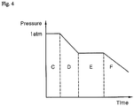
- Fig. 4 is a graph depicting change in pressure inside a heat-insulating layer according to an exemplary embodiment of the present invention.
- the pressures inside the heat-insulating layers 120, 121 are substantially equal to the atmospheric pressure before vacuum drying according to this embodiment is performed (C).
- vacuum drying according to this embodiment is performed (D)
- the pressures inside the heat-insulating layers 120, 121 are gradually reduced.
- the pressures inside the heat insulating layers 120, 121 are maintained substantially constant (E) during continuous vacuum drying, this may mean that the moisture in the plywood is evaporating.
- the moisture of the plywood evaporates while the pressures in the heat-insulating layers 120, 121 are maintained constant (E)
- the water content of the plywood can be controlled by adjusting a period of time for which the pressures in the heat-insulating layers 120, 121 are maintained substantially constant (E).
- the pressures inside the heat-insulating layers 120, 121 may be checked through the vacuum gauges 210, 211 to determine whether moisture in the plywood is evaporating and to adjust the water evaporation time, thereby controlling the water content of the plywood.
- temperature is maintained constant when moisture is evaporating.
- moisture in the plywood is evaporated in the LNG storage tank 100 having good thermal insulation herein, heat of vaporization for evaporation of the moisture in the plywood cannot be sufficiently supplied from the outside. If the heat of vaporization is not sufficiently supplied, the temperature of the plywood is reduced in the process of evaporating the moisture of the plywood. However, when the process of evaporating the moisture of the plywood is continued, the moisture of the plywood is reduced and the required heat of vaporization decreases, or the temperature difference between the inside and the outside of the plywood becomes large, such that heat supply is increased and the temperature of the plywood is increased again.
- the temperature of the plywood which has been reduced during evaporation of the moisture of the plywood, cannot rise and continues to fall.
- the temperature of the plywood falls below zero, the moisture inside the plywood becomes ice. Since sublimation of ice in the plywood into water vapor greatly increases vacuum drying time, when the temperature of the plywood falls below zero, warm gas needs to be supplied to increase the temperature.
- the warm gas supplied when the temperature of the plywood falls below zero is an inert gas, such as argon (Ar), helium (He), or nitrogen (N 2 ). If air outside the heat-insulating layer is supplied as the warm gas, moisture contained in air can be absorbed by the plywood. In addition, the inert gas is less reactive with other materials and is thus safe. In general, nitrogen, which is inexpensive, is mainly used as the warm gas.
- the vacuum hoses 220, 221 connect the vacuum pump 240 to the heat-insulating layers 120, 121 of the LNG storage tank 100 such that air inside the heat-insulating layers 120, 121 can escape into the vacuum pump 240 through the vacuum hoses 220, 221.
- One end of the first vacuum hose 220 is connected to the primary heat-insulating layer 120 and the other end of the first vacuum hose 220 is connected to the vacuum pump 240.
- one end of the second vacuum hose 221 is connected to the secondary heat-insulating layer 121 and the other end of the second vacuum hose 221 is connected to the vacuum pump 240.
- the vacuum filter serves to filter out fine impurities drawn along with air through the vacuum hoses 220, 221. Particularly, when a particulate insulator is used, particles of the insulator can enter the vacuum hoses 220, 221.
- the vacuum filter filters out impurities such as the particles of the insulator to prevent the vacuum hoses 220, 221 from being blocked by the impurities or to prevent the vacuum pump 240 from failing.
- the first vacuum filter 230 is disposed on the first vacuum hose 220 and the second vacuum filter 231 is disposed on the second vacuum hose 221.
- the vacuum pump 240 serves to draw air from the heat-insulating layers 120, 121 through the vacuum hoses 220, 221 each having the other end connected to the vacuum pump 240 to reduce the pressures inside the heat-insulating layers 120, 121.
- the vacuum pump 240 is a common vacuum pump 240, to which both the first vacuum hose 220 connected to the primary heat-insulating layer 120 and the second vacuum hose 221 connected to the secondary heat-insulating layer 121 are connected.
- the vacuum pump 240 In operation of the vacuum pump 240 according to this embodiment, air inside the primary heat-insulating layer 120 and air inside the secondary heat-insulating layer 121 are simultaneously discharged.
- vacuum drying it is desirable that vacuum drying be performed in such a way that, after the second vacuum hose 221 is first connected to the vacuum pump 240 to reduce the pressure inside the secondary heat-insulating layer 121, the first vacuum hose 220 is further connected to the vacuum pump 240 to reduce the pressures in the primary heat-insulating layer 120 and the secondary heat-insulating layer 121 at the same time.
- only the secondary heat-insulating layer 121 may be subjected to vacuum drying without applying vacuum drying to the primary heat-insulating layer 120 so as to keep the internal pressure of the primary heat-insulating layer 120 higher than the internal pressure of the secondary heat-insulating layer 121.
- the vacuum pump 240 may include a plurality of vacuum pumps. In these embodiments, both the first vacuum hose 220 and the second vacuum hose 221 are connected to each of the vacuum pumps 240.
- the other end of the first vacuum hose 220 and the other end of the second vacuum hose 221 may be branched off into the same number of portions as the vacuum pumps 240 to be connected to the respective vacuum pumps 240, or the same number of first vacuum hoses 220 as the vacuum pumps and the same number of second vacuum hoses 221 as the vacuum pumps may be disposed such that the first vacuum hose 220 and the second vacuum hose 221 can be connected to the vacuum pumps 240 in a one-to-one manner.
- the heat-insulating layers 120, 121 of the LNG storage tank 100 may be maintained under vacuum. Heat can be transferred by gas convection. Thus, the heat-insulating layers 120, 121 are maintained under vacuum such that external heat is prevented from being transferred to LNG inside the storage tank 100 by convection of a gas inside the heat insulating layers 120, 121.
- an inert gas such as argon (Ar), helium (He) or nitrogen (N 2 ) be supplied into the heat-insulating layers 120, 121 even when the heat insulating layers 120, 121 are maintained under vacuum. If air outside the heat-insulating layer is supplied into the heat-insulating layers, moisture in the air can be absorbed by the plywood. Further, the inert gas is less reactive with other materials and is thus safe. In general, nitrogen, which is inexpensive, is mainly used.
- Fig. 2 is a schematic side view of an LNG storage tank and vacuum apparatus according to a second embodiment of the present invention.
- the LNG storage tank 100 includes: an internal space 110 in which LNG is stored; a primary heat-insulating layer 120 disposed to surround the internal space 110; and a secondary heat-insulating layer 121 disposed to surround the primary heat insulating layer 120.
- the vacuum apparatus 200 includes: a first vacuum gauge 210 measuring a pressure inside the primary heat-insulating layer 120; a second vacuum gauge 211 measuring a pressure inside the secondary heat-insulating layer 121; a first vacuum hose 220 having one end connected to the primary heat-insulating layer 120; a second vacuum hose 221 having one end connected to the secondary heat-insulating layer 121; a first vacuum filter 230 disposed on the first vacuum hose 220; a second vacuum filter 231 disposed on the second vacuum hose 221; and vacuum pumps 241, 242.
- the vacuum pumps 241, 242 include two types of vacuum pumps, that is, a first vacuum pump 241 connected to the first vacuum hose 220 to draw air from the primary heat-insulating layer 120 and a second vacuum pump 242 connected to the second vacuum hose 221 to draw air from the secondary heat-insulating layer 121.
- the vacuum pumps 241, 242 can separately draw air from the primary heat-insulating layer 120 and from the secondary heat-insulating layer 121, it is not necessary to connect the first vacuum hose 220 to the first vacuum pump 241 before connection of the second vacuum hose 221, as in the first embodiment.
- the internal pressure of the primary heat-insulating layer 120 must be maintained to be higher than the internal pressure of the secondary heat-insulating layer 121, it is desirable that the first vacuum pump 241 and the second vacuum pump 242 be operated together after the first vacuum pump 242 is first operated.
- each of the vacuum pumps 241, 242 may include a plurality of vacuum pumps.
- the first vacuum hose 220 having one end connected to the primary heat-insulating layer 120 is connected to each of the plurality of first vacuum pumps 241
- the second vacuum hose 221 having one end connected to the secondary heat-insulating layer 121 is connected to each of the plurality of second vacuum pumps 242.
- the first vacuum hose 220 may be branched off to be connected to the plurality of first vacuum pumps 241 and the second vacuum hose 221 may be branched off to be connected to the plurality of second vacuum pumps 240, or the same number of first vacuum hoses 220 as the first vacuum pumps 241 and the same number of second vacuum hoses 220 as the second vacuum pumps 242 may be disposed such that the first vacuum hoses 220 and the second vacuum hoses 221 can be respectively connected to the first vacuum pumps 241 and the second vacuum pumps 242 in a one to one manner.
- the first vacuum gauge 210 according to this embodiment is connected to the primary heat-insulating layer 120 of the LNG storage tank 100 to measure the pressure inside the primary heat-insulating layer 120
- the second vacuum gauge 211 according to this embodiment is connected to the secondary heat-insulating layer 121 of the LNG storage tank 100 to measure the pressure inside the secondary heat-insulating layer 121.
- the vacuum hoses 220, 221 connect the vacuum pumps 241, 242 to the heat-insulating layers 120, 121 of the LNG storage tank 100, respectively, such that air inside the heat-insulating layers 120, 121 can escape into the vacuum pumps 241, 242 through the vacuum hoses 220, 221.
- first vacuum hose 220 is connected to the primary heat-insulating layer 120 and the other end of the first vacuum hose 220 is connected to the first vacuum pump 241.
- second vacuum hose 221 is connected to the secondary heat-insulating layer 121 and the other end of the second vacuum hose 221 is connected to the second vacuum pump 242.
- the vacuum filter according to this embodiment serves to filter out fine impurities drawn along with air through the vacuum hose 220, 221.
- the first vacuum filter 230 is disposed on the first vacuum hose 220 and the second vacuum filter 231 is disposed on the second vacuum hose 221.
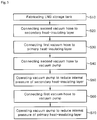
- Fig. 5 is a flowchart of a method of reducing the boil-off rate of an LNG storage tank according to a first embodiment of the present invention.
- the method of reducing the boil-off rate of an LNG storage tank includes: fabricating an LNG storage tank 100 (S10); connecting one end of a second vacuum hose 221 to a secondary heat-insulating layer 121 (S20); connecting one end of a first vacuum hose 220 to a primary heat-insulating layer 120 (S30); connecting the other end of the second vacuum hose 221 to a vacuum pump (S40); operating the vacuum pump to reduce the internal pressure of the secondary heat-insulating layer 121 (S50); connecting the other end of the first vacuum hose 220 to the vacuum pump (S60); and operating the vacuum pump to reduce the internal pressure of the primary heat-insulating layer 121 (S70).
- the other end of the second vacuum hose 221 is connected to the vacuum pump (S40) and the vacuum pump is operated to reduce the internal pressure of the secondary heat-insulating layer 121 to some extent (S50)
- the other end of the first vacuum hose 220 is connected to the vacuum pump (S60) and the vacuum pump is operated to reduce the internal pressures of the primary heat-insulating layer 120 and the secondary heat-insulating layer 121 at the same time (S70)
- the other end of the second vacuum hose 221 is connected to the vacuum pump (S40) and the vacuum pump is operated to evacuate the inner side of the secondary heat-insulating layer 121 to a vacuum (S50)
- the other end of the first vacuum hose 220 is connected to the vacuum pump (S60) and the vacuum pump is operated to evacuate the inner side of the primary heat-insulating layer 121 to a vacuum (S70).
- connecting one end of the first vacuum hose 220 to the primary heat-insulating layer 120 (S30), connecting the other end of the first vacuum hose 220 to the vacuum pump (S60), and operating the vacuum pump to reduce the internal pressure of the primary heat-insulating layer 121 (S70) may be omitted, such that vacuum drying can be applied to only the secondary heat-insulating layer 121 without applying vacuum drying to the primary heat-insulating layer 120.
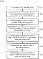
- Fig. 6 is a flowchart of a method of reducing the boil-off rate of an LNG storage tank according to a second embodiment of the present invention.
- the method of reducing the boil-off rate of an LNG storage tank according to this embodiment includes: fabricating an LNG storage tank 100 (S11); connecting one end of a second vacuum hose 221 to a secondary heat-insulating layer 121 (S21); connecting one end of a first vacuum hose 220 to a primary heat-insulating layer 120 (S31); connecting the other end of the second vacuum hose 221 to a vacuum pump (S41); operating the vacuum pump to reduce the internal pressure of the secondary heat-insulating layer 121 (S51); connecting the other end of the first vacuum hose 220 to the vacuum pump (S61); and operating the vacuum pump to reduce the internal pressure of the primary heat-insulating layer 121 (S71).
- first vacuum pump 241 connected to the first vacuum hose 220 to draw air from the primary heat-insulating layer 120 and a second vacuum pump 242 connected to the second vacuum hose 221 to draw air from the secondary heat-insulating layer 121 are used.
- the other end of the second vacuum hose 221 is connected to the second vacuum pump 242 (S41), the second vacuum pump 242 is operated to reduce the internal pressure of the secondary heat-insulating layer 121 (S51), the other end of the first vacuum hose 220 is connected to the first vacuum pump 241 (S61), and the first vacuum pump 241 is operated to reduce the internal pressure of the primary heat-insulating layer 120 (S71).
- first vacuum hose 220 is connected to the first vacuum pump 241 and the second vacuum hose 221 is connected to the second vacuum pump 242, unlike the method of reducing the boil-off rate of an LNG storage tank according to the first embodiment, it is not necessary to connect the other end of the first vacuum hose 220 to the vacuum pump (S61) after connecting the other end of the second vacuum hose 221 to the second vacuum pump 242 (S41).
- the first vacuum pump 241 and the second vacuum pump 242 are operated together to simultaneously reduce the internal pressures of the primary heat-insulating layer 120 and the secondary heat-insulating layer 121 (S71), or, after the second vacuum pump 242 is operated to evacuate the inner side of the secondary heat-insulating layer 121 to a vacuum (S51), the first vacuum pump 241 is operated to evacuate the inner side of the primary heat-insulating layer 120 to a vacuum (S71).
- connecting one end of the first vacuum hose 220 to the primary heat-insulating layer 120 (S31), connecting the other end of the first vacuum hose 220 to the vacuum pump (S61), and operating the vacuum pump to reduce the internal pressure of the primary heat-insulating layer 121 (S71) may be omitted such that vacuum drying can be applied to the secondary heat-insulating layer 121 without applying vacuum drying to the primary heat-insulating layer 120.
Landscapes
- Engineering & Computer Science (AREA)
- Mechanical Engineering (AREA)
- General Engineering & Computer Science (AREA)
- Chemical & Material Sciences (AREA)
- Combustion & Propulsion (AREA)
- Ocean & Marine Engineering (AREA)
- Filling Or Discharging Of Gas Storage Vessels (AREA)
Abstract
Description
- The present invention relates to a method for reducing the boil-off rate of an LNG storage tank and, more particularly, to a method for reducing the boil-off rate of LNG stored in an LNG storage tank by improving insulation performance of the LNG storage tank.
- With growing global interest in eco-friendly businesses, demand for clean fuel, which can replace existing energy sources such as petroleum and coal, is increasing. In this situation, natural gas is used in various fields as a main energy source having cleanliness, stability and convenience. Unlike the US and Europe, where natural gas is directly supplied through pipelines, Korea introduced liquefied natural gas (hereinafter, "LNG") obtained by liquefying natural gas at an extremely low temperature and has supplied LNG to consumers. Thus, the demand for an LNG storage tank is increasing along with increase in domestic natural gas demand.
- LNG is obtained by cooling natural gas to an extremely low temperature (about -163°C) and is suitable for long-distance transportation by sea since LNG is significantly reduced in volume, as compared with natural gas in a gaseous state. LNG carriers are designed to carry liquefied gas to an onshore source of demand and, for this purpose, include a storage tank capable of withstanding ultra-low temperatures of LNG.
- Such a storage tank is divided into an independent tank-type and a membrane-type depending on whether the weight of cargo is directly applied to an insulator. The membrane-type storage tank is divided into a GTT NO 96-type and a Mark III-type, and the independent tank-type storage tank is divided into a MOSS-type and an IHI-SPB-type. The GTT NO 96-type and GTT Mark III-type were formerly called a GT type and a TGZ type. After Gas Transport (GT) and Technigaz (TGZ) were renamed to GTT (Gaztransport & Technigaz) in 1995, the GT type and the TGZ type have been referred to as the GTT NO 96-type and the GTT Mark III-type, respectively.
- For a membrane-type LNG storage tank, insulation performance is secured by an insulation box or an insulation panel. Plywood is widely used as a material for an insulating box or an insulating panel. Plywood is evaluated as the most competitive material among materials that can function as a load bearing structural material, as an insulator for preventing heat penetration from the outside, and as a container for storing other materials.
- Generally, plywood has a water content of about 10% to 15%. As the water content decreases, the thermal conductivity of the plywood is reduced. When the thermal conductivity of the plywood is reduced, the thermal conductivity of the insulation box or the insulation panel is also reduced, thereby causing increase in insulation performance of the storage tank.
- Plywood used in typical LNG storage tanks has a water content of 10% to 15%, and has a higher thermal conductivity than an insulation box or an insulation panel including the plywood. Thus, the plywood used in typical LNG storage tanks contributes to deterioration in insulation performance of the insulation box or the insulation panel and thus increase in boil-off rate (BOR) of LNG stored in the storage tank.
- Embodiments of the present invention have been conceived to solve such a problem in the art and provide a method for reducing the boil-off rate of an LNG storage tank, which includes operating a vacuum pump to reduce an internal pressure of a heat-insulating layer of the LNG storage tank.
- In accordance with one aspect of the present invention, a method for reducing a boil-off rate of an LNG storage tank includes: fabricating an LNG storage tank including a primary heat-insulating layer and a secondary heat-insulating layer; connecting one end of a second vacuum hose to the secondary heat-insulating layer; connecting the other end of the second vacuum hose to a vacuum pump; and operating the vacuum pump to reduce the internal pressure of the secondary heat-insulating layer, wherein an inner side of the secondary heat-insulating layer is evacuated to a vacuum to reduce the water content of plywood contained in the secondary heat-insulating layer.
- The method may further include: connecting one end of a first vacuum hose to the primary heat-insulating layer of the LNG storage tank; connecting the other end of the first vacuum hose to the vacuum pump; and operating the vacuum pump to reduce the internal pressure of the primary heat-insulating layer, wherein the inside of the primary heat-insulating layer may be evacuated to a vacuum to reduce the water content of plywood contained in the primary heat-insulating layer, and the internal pressure of the primary heat-insulating layer may be maintained to be higher than the internal pressure of the secondary heat-insulating layer during performing the method for reducing the boil-off rate of the LNG storage tank.
- The vacuum pump may include a plurality of vacuum pumps, each of which may be connected to the other end of the first vacuum hose and the other end of the second vacuum hose.
- The first vacuum hose and the second vacuum hose may include the same number of first vacuum hoses as the vacuum pumps and the same number of second vacuum hoses as the vacuum pumps, respectively, such that the other ends of the first vacuum hoses and the other ends of the second vacuum hoses are connected to the vacuum pumps in a one-to-one manner.
- One end of the first vacuum hose may be connected to the primary heat-insulating layer; one end of the second vacuum hose may be connected to the secondary heat-insulating layer; the other end of the first vacuum hose may be branched off into the same number of portions as the vacuum pumps to be connected to the respective vacuum pumps; and the other end of the second vacuum hose may be branched off into the same number of portions as the vacuum pumps to be connected to the respective vacuum pumps.
- The other end of the first vacuum hose may be connected to a first vacuum pump and the other end of the second vacuum hose may be connected to a second vacuum pump.
- The first vacuum pump and the second vacuum pump may include a plurality of first vacuum pumps and a plurality of second vacuum pumps, respectively, wherein each of the first vacuum pumps may be connected to the other end of the first vacuum hose and each of the second vacuum pumps may be connected to the other end of the second vacuum hose.
- The first vacuum hose may include the same number of first vacuum hoses as the first vacuum pumps such that the other ends of the first vacuum hoses are connected to the first vacuum pumps in a one-to-one manner, and the second vacuum hose may include the same number of second vacuum hoses as the second vacuum pumps such that the other ends of the second vacuum hoses are connected to the second vacuum pumps in a one-to-one manner.
- One end of the first vacuum hose may be connected to the primary heat-insulating layer; one end of the second vacuum hose may be connected to the secondary heat-insulating layer; the other end of the first vacuum hose may be branched off into the same number of portions as the first vacuum pumps to be connected to the respective first vacuum pumps; and the other end of the second vacuum hose may be branched off into the same number of portions as the second vacuum pumps to be connected to the respective second vacuum pumps.
- The water content of plywood may be controlled by adjusting a period of time for which internal pressures of the primary heat-insulating layer and the secondary heat-insulating layer are maintained constant.
- The method may further include: supplying a gas having a temperature higher than or equal to room temperature to the primary heat-insulating layer when the temperature of plywood contained in the primary heat-insulating layer drops below zero, and supplying a gas having a temperature higher than or equal to room temperature to the secondary heat-insulating layer when the temperature of plywood contained in the secondary heat-insulating layer drops below zero.
- The gas may include any one of argon, helium, and nitrogen.
- At least one of the primary heat-insulating layer and the secondary heat-insulating layer may be maintained under vacuum after the water content of the plywood is reduced.
- The method may further include supplying a gas to at least one of the primary heat-insulating layer and the secondary heat-insulating layer after the water content of the plywood is reduced.
- The gas may include any one of argon, helium, and nitrogen.
- In accordance with another aspect of the present invention, a method for reducing a boil-off rate of an LNG storage tank includes: fabricating an LNG storage tank comprising a heat-insulating layer; connecting one end of a vacuum hose to the heat-insulating layer; connecting the other end of the vacuum hose to a vacuum pump; and operating the vacuum pump to reduce the internal pressure of the heat-insulating layer, wherein the inside of the heat-insulating layer is evacuated to a vacuum to reduce the water content of plywood contained in the heat-insulating layer.
- In accordance with a further aspect of the present invention, a vacuum apparatus includes: a vacuum hose having one end connected to a heat-insulating layer of an LNG storage tank; and a vacuum pump connected to the other end of the vacuum hose, wherein the vacuum pump is operated to evacuate an inner side of the heat-insulating layer to a vacuum to reduce the water content of plywood contained in the heat-insulating layer.
- The vacuum apparatus may further include a vacuum gauge measuring a pressure inside the heat-insulating layer.
- The vacuum apparatus may further include a vacuum filter installed on the vacuum hose to filter out impurities.
- Embodiments of the present invention provide a method for reducing a boil-off rate of an LNG storage tank, which can reduce the water content of plywood used in the LNG storage tank, thereby increasing thermal conductivity of an insulation box and insulation panel including the plywood while increasing insulation performance of the LNG storage tank to reduce the BOR of LNG stored in the storage tank.
- An LNG storage tank stores LNG in a liquid state and the LNG is easily vaporized due to a very low vaporization point thereof (about -162°C). Thus, avoiding vaporization of the LNG during transportation is one of the most important challenges in design of the LNG storage tank. Therefore, the ability to reduce the BOR of LNG in the LNG storage tank means that LNG transport can be performed efficiently and economically.
- In addition, embodiments of the present invention provide a method for reducing a boil-off rate of an LNG storage tank, which can use plywood, which is the most competitive material among materials capable of functioning as a structural material, an insulator and the like, as an insulator for the LNG storage tank, instead of other materials having a higher water content than plywood, while reducing the water content of the plywood, thereby reducing thermal conductivity of the LNG storage tank while adopting advantages of plywood.
- Further, as in a typical method, plywood can be subjected to vacuum drying after the LNG storage tank is constructed, whereby the water content of the plywood can be reduced easily and quickly.
-
-
Fig. 1 is a schematic side view of an LNG storage tank and vacuum apparatus according to a first embodiment of the present invention. -
Fig. 2 is a schematic side view of an LNG storage tank and vacuum apparatus according to a second embodiment of the present invention. -
Fig. 3 is a state diagram of water according to changes in temperature and pressure. -
Fig. 4 is a graph depicting change in pressure inside a heat-insulating layer according to an exemplary embodiment of the present invention. -
Fig. 5 is a flowchart of a method for reducing a boil-off rate of an LNG storage tank according to a first embodiment of the present invention. -
Fig. 6 is a flowchart of a method for reducing a boil-off rate of an LNG storage tank according to a second embodiment of the present invention. - Hereinafter, embodiments of the present invention will be described with reference to the accompanying drawings. A method for reducing a boil-off rate of an LNG storage tank according to the following embodiments may be applied to all marine structures designed for LNG transportation. In addition, it should be understood that the present invention is not limited to the following embodiments, and that various modifications, substitutions, and equivalent embodiments can be made by those skilled in the art without departing from the spirit and scope of the present invention.
-
Fig. 1 is a schematic side view of an LNG storage tank and vacuum apparatus according to a first embodiment of the present invention. - Referring to
Fig. 1 , anLNG storage tank 100 includes: aninternal space 110 in which LNG is stored; a primary heat-insulating layer 120 disposed to surround theinternal space 110; and a secondary heat-insulating layer 121 disposed to surround the primaryheat insulating layer 120. - Generally, the
LNG storage tank 100 is constructed through a process in which the secondary heat-insulatinglayer 121 is disposed on a hull, a secondary sealing wall is disposed on the secondary heat-insulating layer, the primary heat-insulatinglayer 120 is disposed on the secondary sealing wall, and a primary sealing wall is disposed on the primary heat-insulating layer. - The primary sealing wall and the secondary sealing wall prevent LNG from flowing out of the
storage tank 100, and the primary heat-insulatinglayer 120 and the secondary heat-insulatinglayer 121 insulate theinternal space 110 from the outside to keep the temperature of theinternal space 110 such that LNG stored in theinternal space 110 is not vaporized. - The
vacuum apparatus 200 according to this embodiment includes: afirst vacuum gauge 210 measuring a pressure inside the primary heat-insulatinglayer 120; asecond vacuum gauge 211 measuring a pressure inside the secondary heat-insulatinglayer 121; afirst vacuum hose 220 having one end connected to the primary heat-insulatinglayer 120; asecond vacuum hose 221 having one end connected to the secondary heat-insulatinglayer 121; afirst vacuum filter 230 disposed on thefirst vacuum hose 220; asecond vacuum filter 231 disposed on thesecond vacuum hose 221; and avacuum pump 240 to which the other end of thefirst vacuum hose 220 and the other end of thesecond vacuum hose 221 are connected. - The
first vacuum gauge 210 is connected to the primary heat-insulatinglayer 120 of theLNG storage tank 100 to measure the pressure inside the primary heat-insulatinglayer 120 and thesecond vacuum gauge 211 is connected to the secondary heat-insulatinglayer 121 of theLNG storage tank 100 to measure the pressure inside the secondary heat-insulatinglayer 121. - The pressures inside the heat-insulating
layers LNG storage tank 100 can be checked in real time through the vacuum gauges 210, 211, respectively. Since the secondary heat-insulatinglayer 121 is formed to surround the primary heat-insulatinglayer 120, if the pressure of the primary heat-insulatinglayer 120 becomes lower than the pressure of the secondary heat-insulatinglayer 121, thestorage tank 100 can be damaged. Therefore, in implementation of the present invention, it is very important to keep the pressure of the primary heat-insulatinglayer 120 higher than the pressure of the secondary heat-insulatinglayer 121. The vacuum gauges 210, 211 may be used to continuously check whether the pressure of the primary heat-insulatinglayer 120 is higher than the pressure of the secondary heat-insulatinglayer 121. - Herein, vacuum drying refers to a drying method of evaporating moisture of a material by lowering a pressure to a vapor pressure at which the moisture can evaporate. The pressures of the heat-insulating
layers -
Fig. 3 is a state diagram of water according to changes in temperature and pressure. - Referring to
Fig. 3 , it can be seen that when the pressure is lower than the vapor pressure at a temperature higher than the temperature at the triple point (T) where the melting curve (X), the vapor pressure curve (Y), and the sublimation curve (Z) meet one another, (A) water in a liquid state turns into (B) vapor in a gaseous state. Vacuum drying is based on the fact that water can be vaporized by lowering the pressure at a given temperature. - In this embodiment, for efficient vacuum drying, the pressures inside the heat-insulating
layers -
Fig. 4 is a graph depicting change in pressure inside a heat-insulating layer according to an exemplary embodiment of the present invention. - Referring to
Fig. 4 , the pressures inside the heat-insulatinglayers layers - There is a section in which the pressures inside the heat-insulating
layers vacuum apparatus 200 is continuously operated to reduce the pressures. This is because the pressures inside the heat-insulatinglayers layers vacuum apparatus 200, the water vapor increases the pressures inside the heat-insulatinglayers layers layers layers - Thus, if the pressures inside the
heat insulating layers layers layers - In other words, the pressures inside the heat-insulating
layers - In general, temperature is maintained constant when moisture is evaporating. However, since moisture in the plywood is evaporated in the
LNG storage tank 100 having good thermal insulation herein, heat of vaporization for evaporation of the moisture in the plywood cannot be sufficiently supplied from the outside. If the heat of vaporization is not sufficiently supplied, the temperature of the plywood is reduced in the process of evaporating the moisture of the plywood. However, when the process of evaporating the moisture of the plywood is continued, the moisture of the plywood is reduced and the required heat of vaporization decreases, or the temperature difference between the inside and the outside of the plywood becomes large, such that heat supply is increased and the temperature of the plywood is increased again. - In some cases, the temperature of the plywood, which has been reduced during evaporation of the moisture of the plywood, cannot rise and continues to fall. When the temperature of the plywood falls below zero, the moisture inside the plywood becomes ice. Since sublimation of ice in the plywood into water vapor greatly increases vacuum drying time, when the temperature of the plywood falls below zero, warm gas needs to be supplied to increase the temperature.
- Since vacuum is broken upon supply of the gas, a process of re-evacuating the inner sides of the heat-insulating
layers - Preferably, the warm gas supplied when the temperature of the plywood falls below zero is an inert gas, such as argon (Ar), helium (He), or nitrogen (N2). If air outside the heat-insulating layer is supplied as the warm gas, moisture contained in air can be absorbed by the plywood. In addition, the inert gas is less reactive with other materials and is thus safe. In general, nitrogen, which is inexpensive, is mainly used as the warm gas.
- The
vacuum hoses vacuum pump 240 to the heat-insulatinglayers LNG storage tank 100 such that air inside the heat-insulatinglayers vacuum pump 240 through thevacuum hoses first vacuum hose 220 is connected to the primary heat-insulatinglayer 120 and the other end of thefirst vacuum hose 220 is connected to thevacuum pump 240. In addition, one end of thesecond vacuum hose 221 is connected to the secondary heat-insulatinglayer 121 and the other end of thesecond vacuum hose 221 is connected to thevacuum pump 240. - The vacuum filter serves to filter out fine impurities drawn along with air through the
vacuum hoses vacuum hoses vacuum hoses vacuum pump 240 from failing. Thefirst vacuum filter 230 is disposed on thefirst vacuum hose 220 and thesecond vacuum filter 231 is disposed on thesecond vacuum hose 221. - The
vacuum pump 240 serves to draw air from the heat-insulatinglayers vacuum hoses vacuum pump 240 to reduce the pressures inside the heat-insulatinglayers vacuum pump 240 is acommon vacuum pump 240, to which both thefirst vacuum hose 220 connected to the primary heat-insulatinglayer 120 and thesecond vacuum hose 221 connected to the secondary heat-insulatinglayer 121 are connected. - In operation of the
vacuum pump 240 according to this embodiment, air inside the primary heat-insulatinglayer 120 and air inside the secondary heat-insulatinglayer 121 are simultaneously discharged. Thus, in order to keep the internal pressure of the primary heat-insulatinglayer 120 higher than the internal pressure of the secondary heat-insulatinglayer 121, it is desirable that vacuum drying be performed in such a way that, after thesecond vacuum hose 221 is first connected to thevacuum pump 240 to reduce the pressure inside the secondary heat-insulatinglayer 121, thefirst vacuum hose 220 is further connected to thevacuum pump 240 to reduce the pressures in the primary heat-insulatinglayer 120 and the secondary heat-insulatinglayer 121 at the same time. - Alternatively, only the secondary heat-insulating
layer 121 may be subjected to vacuum drying without applying vacuum drying to the primary heat-insulatinglayer 120 so as to keep the internal pressure of the primary heat-insulatinglayer 120 higher than the internal pressure of the secondary heat-insulatinglayer 121. - It some embodiments, the
vacuum pump 240 may include a plurality of vacuum pumps. In these embodiments, both thefirst vacuum hose 220 and thesecond vacuum hose 221 are connected to each of the vacuum pumps 240. - In an embodiment wherein the
vacuum pump 240 includes a plurality of vacuum pumps, the other end of thefirst vacuum hose 220 and the other end of thesecond vacuum hose 221 may be branched off into the same number of portions as thevacuum pumps 240 to be connected to therespective vacuum pumps 240, or the same number offirst vacuum hoses 220 as the vacuum pumps and the same number ofsecond vacuum hoses 221 as the vacuum pumps may be disposed such that thefirst vacuum hose 220 and thesecond vacuum hose 221 can be connected to thevacuum pumps 240 in a one-to-one manner. - In order to improve heat insulation of the
LNG storage tank 100, the heat-insulatinglayers LNG storage tank 100 may be maintained under vacuum. Heat can be transferred by gas convection. Thus, the heat-insulatinglayers storage tank 100 by convection of a gas inside theheat insulating layers - It is desirable that an inert gas such as argon (Ar), helium (He) or nitrogen (N2) be supplied into the heat-insulating
layers heat insulating layers -
Fig. 2 is a schematic side view of an LNG storage tank and vacuum apparatus according to a second embodiment of the present invention. - Like the
LNG storage tank 100 according to the first embodiment, theLNG storage tank 100 according to this embodiment includes: aninternal space 110 in which LNG is stored; a primary heat-insulatinglayer 120 disposed to surround theinternal space 110; and a secondary heat-insulatinglayer 121 disposed to surround the primaryheat insulating layer 120. - In addition, like the
vacuum apparatus 200 according to the first embodiment, thevacuum apparatus 200 according to this embodiment includes: afirst vacuum gauge 210 measuring a pressure inside the primary heat-insulatinglayer 120; asecond vacuum gauge 211 measuring a pressure inside the secondary heat-insulatinglayer 121; afirst vacuum hose 220 having one end connected to the primary heat-insulatinglayer 120; asecond vacuum hose 221 having one end connected to the secondary heat-insulatinglayer 121; afirst vacuum filter 230 disposed on thefirst vacuum hose 220; asecond vacuum filter 231 disposed on thesecond vacuum hose 221; andvacuum pumps - Unlike the
vacuum pump 240 according to the first embodiment, thevacuum pumps first vacuum pump 241 connected to thefirst vacuum hose 220 to draw air from the primary heat-insulatinglayer 120 and asecond vacuum pump 242 connected to thesecond vacuum hose 221 to draw air from the secondary heat-insulatinglayer 121. - Thus, since the
vacuum pumps layer 120 and from the secondary heat-insulatinglayer 121, it is not necessary to connect thefirst vacuum hose 220 to thefirst vacuum pump 241 before connection of thesecond vacuum hose 221, as in the first embodiment. However, since the internal pressure of the primary heat-insulatinglayer 120 must be maintained to be higher than the internal pressure of the secondary heat-insulatinglayer 121, it is desirable that thefirst vacuum pump 241 and thesecond vacuum pump 242 be operated together after thefirst vacuum pump 242 is first operated. - Like the
vacuum pump 240 according to the first embodiment, each of thevacuum pumps first vacuum hose 220 having one end connected to the primary heat-insulatinglayer 120 is connected to each of the plurality offirst vacuum pumps 241, and thesecond vacuum hose 221 having one end connected to the secondary heat-insulatinglayer 121 is connected to each of the plurality of second vacuum pumps 242. - When each of the
vacuum pumps first vacuum hose 220 may be branched off to be connected to the plurality offirst vacuum pumps 241 and thesecond vacuum hose 221 may be branched off to be connected to the plurality ofsecond vacuum pumps 240, or the same number offirst vacuum hoses 220 as thefirst vacuum pumps 241 and the same number ofsecond vacuum hoses 220 as thesecond vacuum pumps 242 may be disposed such that thefirst vacuum hoses 220 and thesecond vacuum hoses 221 can be respectively connected to thefirst vacuum pumps 241 and thesecond vacuum pumps 242 in a one to one manner. - Like the
first vacuum gauge 210 according to the first embodiment, thefirst vacuum gauge 210 according to this embodiment is connected to the primary heat-insulatinglayer 120 of theLNG storage tank 100 to measure the pressure inside the primary heat-insulatinglayer 120, and, like thesecond vacuum gauge 211 according to the first embodiment, thesecond vacuum gauge 211 according to this embodiment is connected to the secondary heat-insulatinglayer 121 of theLNG storage tank 100 to measure the pressure inside the secondary heat-insulatinglayer 121. - Like the
vacuum hoses vacuum hoses vacuum pumps layers LNG storage tank 100, respectively, such that air inside the heat-insulatinglayers vacuum pumps vacuum hoses - However, one end of the
first vacuum hose 220 according to this embodiment is connected to the primary heat-insulatinglayer 120 and the other end of thefirst vacuum hose 220 is connected to thefirst vacuum pump 241. In addition, one end of thesecond vacuum hose 221 is connected to the secondary heat-insulatinglayer 121 and the other end of thesecond vacuum hose 221 is connected to thesecond vacuum pump 242. - Like the vacuum filter according to the first embodiment, the vacuum filter according to this embodiment serves to filter out fine impurities drawn along with air through the
vacuum hose first vacuum filter 230 is disposed on thefirst vacuum hose 220 and thesecond vacuum filter 231 is disposed on thesecond vacuum hose 221. -
Fig. 5 is a flowchart of a method of reducing the boil-off rate of an LNG storage tank according to a first embodiment of the present invention. - Referring to
Fig. 5 , the method of reducing the boil-off rate of an LNG storage tank according to this embodiment includes: fabricating an LNG storage tank 100 (S10); connecting one end of asecond vacuum hose 221 to a secondary heat-insulating layer 121 (S20); connecting one end of afirst vacuum hose 220 to a primary heat-insulating layer 120 (S30); connecting the other end of thesecond vacuum hose 221 to a vacuum pump (S40); operating the vacuum pump to reduce the internal pressure of the secondary heat-insulating layer 121 (S50); connecting the other end of thefirst vacuum hose 220 to the vacuum pump (S60); and operating the vacuum pump to reduce the internal pressure of the primary heat-insulating layer 121 (S70). - In order to keep the internal pressure of the primary heat-insulating
layer 120 higher than the internal pressure of the secondary heat-insulatinglayer 121 during operation of reducing the boil-off rate of an LNG storage tank according to this embodiment, it is desirable that connecting the other end of thefirst vacuum hose 220 to the vacuum pump (S60) be performed after connecting the other end of thesecond vacuum hose 221 to the vacuum pump (S40). - That is, after the other end of the
second vacuum hose 221 is connected to the vacuum pump (S40) and the vacuum pump is operated to reduce the internal pressure of the secondary heat-insulatinglayer 121 to some extent (S50), the other end of thefirst vacuum hose 220 is connected to the vacuum pump (S60) and the vacuum pump is operated to reduce the internal pressures of the primary heat-insulatinglayer 120 and the secondary heat-insulatinglayer 121 at the same time (S70), or, after the other end of thesecond vacuum hose 221 is connected to the vacuum pump (S40) and the vacuum pump is operated to evacuate the inner side of the secondary heat-insulatinglayer 121 to a vacuum (S50), the other end of thefirst vacuum hose 220 is connected to the vacuum pump (S60) and the vacuum pump is operated to evacuate the inner side of the primary heat-insulatinglayer 121 to a vacuum (S70). - Alternatively, connecting one end of the
first vacuum hose 220 to the primary heat-insulating layer 120 (S30), connecting the other end of thefirst vacuum hose 220 to the vacuum pump (S60), and operating the vacuum pump to reduce the internal pressure of the primary heat-insulating layer 121 (S70) may be omitted, such that vacuum drying can be applied to only the secondary heat-insulatinglayer 121 without applying vacuum drying to the primary heat-insulatinglayer 120. -
Fig. 6 is a flowchart of a method of reducing the boil-off rate of an LNG storage tank according to a second embodiment of the present invention. - Referring to
Fig. 6 , as in the method of reducing the boil-off rate of an LNG storage tank according to the first embodiment, the method of reducing the boil-off rate of an LNG storage tank according to this embodiment includes: fabricating an LNG storage tank 100 (S11); connecting one end of asecond vacuum hose 221 to a secondary heat-insulating layer 121 (S21); connecting one end of afirst vacuum hose 220 to a primary heat-insulating layer 120 (S31); connecting the other end of thesecond vacuum hose 221 to a vacuum pump (S41); operating the vacuum pump to reduce the internal pressure of the secondary heat-insulating layer 121 (S51); connecting the other end of thefirst vacuum hose 220 to the vacuum pump (S61); and operating the vacuum pump to reduce the internal pressure of the primary heat-insulating layer 121 (S71). - However, unlike the method of reducing the boil-off rate of an LNG storage tank according to the first embodiment, in this embodiment, two types of vacuum pumps, that is, a
first vacuum pump 241 connected to thefirst vacuum hose 220 to draw air from the primary heat-insulatinglayer 120 and asecond vacuum pump 242 connected to thesecond vacuum hose 221 to draw air from the secondary heat-insulatinglayer 121 are used. Thus, the other end of thesecond vacuum hose 221 is connected to the second vacuum pump 242 (S41), thesecond vacuum pump 242 is operated to reduce the internal pressure of the secondary heat-insulating layer 121 (S51), the other end of thefirst vacuum hose 220 is connected to the first vacuum pump 241 (S61), and thefirst vacuum pump 241 is operated to reduce the internal pressure of the primary heat-insulating layer 120 (S71). - In this embodiment, since the
first vacuum hose 220 is connected to thefirst vacuum pump 241 and thesecond vacuum hose 221 is connected to thesecond vacuum pump 242, unlike the method of reducing the boil-off rate of an LNG storage tank according to the first embodiment, it is not necessary to connect the other end of thefirst vacuum hose 220 to the vacuum pump (S61) after connecting the other end of thesecond vacuum hose 221 to the second vacuum pump 242 (S41). - However, as in the method of reducing the boil-off rate of an LNG storage tank according to the first embodiment, in order to keep the internal pressure of the primary heat-insulating
layer 120 higher than the internal pressure of the secondary heat-insulatinglayer 121 during operation of reducing the boil-off rate of an LNG storage tank according to this embodiment, after thesecond vacuum pump 242 is operated to reduce the internal pressure of the secondary heat-insulatinglayer 121 to some extent (S51), thefirst vacuum pump 241 and thesecond vacuum pump 242 are operated together to simultaneously reduce the internal pressures of the primary heat-insulatinglayer 120 and the secondary heat-insulating layer 121 (S71), or, after thesecond vacuum pump 242 is operated to evacuate the inner side of the secondary heat-insulatinglayer 121 to a vacuum (S51), thefirst vacuum pump 241 is operated to evacuate the inner side of the primary heat-insulatinglayer 120 to a vacuum (S71). - Further, as in the method of reducing the boil-off rate of an LNG storage tank according to the first embodiment, in the method according to this embodiment, connecting one end of the
first vacuum hose 220 to the primary heat-insulating layer 120 (S31), connecting the other end of thefirst vacuum hose 220 to the vacuum pump (S61), and operating the vacuum pump to reduce the internal pressure of the primary heat-insulating layer 121 (S71) may be omitted such that vacuum drying can be applied to the secondary heat-insulatinglayer 121 without applying vacuum drying to the primary heat-insulatinglayer 120. - Although some embodiments have been described herein, it should be understood that these embodiments are provided for illustration only and are not to be construed in any way as limiting the present invention, and that various modifications, changes, alterations, and equivalent embodiments can be made by those skilled in the art without departing from the spirit and scope of the invention.
Claims (19)
- A method of reducing a boil-off rate of an LNG storage tank, comprising:fabricating an LNG storage tank comprising a primary heat-insulating layer and a secondary heat-insulating layer;connecting one end of a second vacuum hose to the secondary heat-insulating layer;connecting the other end of the second vacuum hose to a vacuum pump; andoperating the vacuum pump to reduce an internal pressure of the secondary heat-insulating layer,wherein an inner side of the secondary heat-insulating layer is evacuated to a vacuum to reduce a water content of plywood contained in the secondary heat-insulating layer.
- The method according to claim 1, further comprising:connecting one end of a first vacuum hose to the primary heat-insulating layer of the LNG storage tank;connecting the other end of the first vacuum hose to the vacuum pump; andoperating the vacuum pump to reduce an internal pressure of the primary heat-insulating layer,wherein an inner side of the primary heat-insulating layer is evacuated to a vacuum to reduce a water content of plywood contained in the primary heat-insulating layer, and an internal pressure of the primary heat-insulating layer is maintained to be higher than an internal pressure of the secondary heat-insulating layer during operation of reducing the boil-off rate of the LNG storage tank.
- The method according to claim 2, wherein the vacuum pump comprises a plurality of vacuum pumps, each being connected to the other end of the first vacuum hose and the other end of the second vacuum hose.
- The method according to claim 3, wherein the first vacuum hose and the second vacuum hose comprise the same number of first vacuum hoses as the vacuum pumps and the same number of second vacuum hoses as the vacuum pumps, respectively, such that the other ends of the first vacuum hoses and the other ends of the second vacuum hoses are connected to the vacuum pumps in a one-to-one manner.
- The method according to claim 3, wherein one end of the first vacuum hose is connected to the primary heat-insulating layer; one end of the second vacuum hose is connected to the secondary heat-insulating layer; the other end of the first vacuum hose is branched off into the same number of portions as the vacuum pumps to be connected to the respective vacuum pumps; and the other end of the second vacuum hose is branched off into the same number of portions as the vacuum pumps to be connected to the respective vacuum pumps.
- The method according to claim 2, wherein the other end of the first vacuum hose is connected to a first vacuum pump and the other end of the second vacuum hose is connected to a second vacuum pump.
- The method according to claim 6, wherein the first vacuum pump and the second vacuum pump comprise a plurality of first vacuum pumps and a plurality of second vacuum pumps, respectively, and wherein each of the first vacuum pumps is connected to the other end of the first vacuum hose and each of the second vacuum pumps is connected to the other end of the second vacuum hose.
- The method according to claim 7, wherein the first vacuum hose comprises the same number of first vacuum hoses as the first vacuum pumps such that the other ends of the first vacuum hoses are connected to the first vacuum pumps in a one-to-one manner, and the second vacuum hose comprises the same number of second vacuum hoses as the second vacuum pumps such that the other ends of the second vacuum hoses are connected to the second vacuum pumps in a one-to-one manner.
- The method according to claim 7, wherein one end of the first vacuum hose is connected to the primary heat-insulating layer; one end of the second vacuum hose is connected to the secondary heat-insulating layer; the other end of the first vacuum hose is branched off into the same number of portions as the first vacuum pumps to be connected to the respective first vacuum pumps; and the other end of the second vacuum hose is branched off into the same number of portions as the second vacuum pumps to be connected to the respective second vacuum pumps.
- The method according to any one of claims 2 to 9, wherein the water content of plywood is controlled by adjusting a period of time for which internal pressures of the primary heat-insulating layer and the secondary heat-insulating layer are maintained constant.
- The method according to any one of claims 2 to 9, further comprising:supplying a gas having a temperature higher than or equal to room temperature to the primary heat-insulating layer when a temperature of plywood contained in the primary heat-insulating layer drops below zero and supplying a gas having a temperature higher than or equal to room temperature to the secondary heat-insulating layer when a temperature of plywood contained in the secondary heat-insulating layer drops below zero.
- The method according to claim 11, wherein the gas comprises any one of argon, helium, and nitrogen.
- The method according to any one of claims 2 to 9, wherein at least one of the primary heat-insulating layer and the secondary heat-insulating layer is maintained under vacuum after the water content of the plywood is reduced.
- The method according to any one of claims 2 to 9, further comprising: supplying a gas to at least one of the primary heat-insulating layer and the secondary heat-insulating layer after the water content of the plywood is reduced.
- The method according to claim 14, wherein the gas comprises any one of argon, helium, and nitrogen.
- A method of reducing a boil-off rate of an LNG storage tank, comprising:fabricating an LNG storage tank comprising a heat-insulating layer;connecting one end of a vacuum hose to the heat-insulating layer;connecting the other end of the vacuum hose to a vacuum pump; andoperating the vacuum pump to reduce an internal pressure of the heat-insulating layer,wherein an inner side of the heat-insulating layer is evacuated to a vacuum to reduce a water content of plywood contained in the heat-insulating layer.
- A vacuum apparatus comprising:a vacuum hose having one end connected to a heat-insulating layer of an LNG storage tank; anda vacuum pump connected to the other end of the vacuum hose,wherein the vacuum pump is operated to evacuate an inner side of the heat-insulating layer to a vacuum to reduce a water content of plywood contained in the heat-insulating layer.
- The vacuum apparatus according to claim 17, further comprising: a vacuum gauge measuring a pressure inside the heat-insulating layer.
- The vacuum apparatus according to claim 17, further comprising: a vacuum filter installed on the vacuum hose to filter out impurities.
Applications Claiming Priority (2)
| Application Number | Priority Date | Filing Date | Title |
|---|---|---|---|
| KR1020140128954A KR20160036837A (en) | 2014-09-26 | 2014-09-26 | Boil-off Rate Reduction Method for Liquified Natural Gas Storage Tank |
| PCT/KR2015/010083 WO2016048057A1 (en) | 2014-09-26 | 2015-09-24 | Method for reducing natural evaporation rate of lng storage tank |
Publications (2)
| Publication Number | Publication Date |
|---|---|
| EP3199446A1 true EP3199446A1 (en) | 2017-08-02 |
| EP3199446A4 EP3199446A4 (en) | 2018-05-02 |
Family
ID=55581485
Family Applications (1)
| Application Number | Title | Priority Date | Filing Date |
|---|---|---|---|
| EP15845368.8A Withdrawn EP3199446A4 (en) | 2014-09-26 | 2015-09-24 | Method for reducing natural evaporation rate of lng storage tank |
Country Status (6)
| Country | Link |
|---|---|
| US (1) | US20170299118A1 (en) |
| EP (1) | EP3199446A4 (en) |
| KR (1) | KR20160036837A (en) |
| CN (1) | CN107076357A (en) |
| SG (1) | SG11201702109UA (en) |
| WO (1) | WO2016048057A1 (en) |
Cited By (2)
| Publication number | Priority date | Publication date | Assignee | Title |
|---|---|---|---|---|
| WO2023012045A1 (en) * | 2021-08-02 | 2023-02-09 | Shell Internationale Research Maatschappij B.V. | Containment system for liquid hydrogen |
| WO2023167595A1 (en) * | 2022-03-03 | 2023-09-07 | Lattice International AS | Membrane tank feasible for cryogenic service |
Families Citing this family (5)
| Publication number | Priority date | Publication date | Assignee | Title |
|---|---|---|---|---|
| JP7323990B2 (en) * | 2018-07-10 | 2023-08-09 | 川崎重工業株式会社 | Dew point temperature adjustment device and dew point temperature adjustment method |
| JP7273508B2 (en) * | 2018-12-28 | 2023-05-15 | 川崎重工業株式会社 | vessel |
| FR3128153A1 (en) * | 2021-10-18 | 2023-04-21 | Airbus | Composite structure provided with a hollow fiber thermal protection device, in particular for a liquid hydrogen tank. |
| CN114562675B (en) * | 2022-02-23 | 2023-08-04 | 中太(苏州)氢能源科技有限公司 | Metal storage cabin for storing liquid hydrogen and liquid helium |
| KR20230143585A (en) * | 2023-05-30 | 2023-10-12 | 에이치디한국조선해양 주식회사 | Insulated tank and vessel including the same |
Family Cites Families (8)
| Publication number | Priority date | Publication date | Assignee | Title |
|---|---|---|---|---|
| JPS5948256B2 (en) * | 1975-10-04 | 1984-11-26 | 千代田化工建設株式会社 | Basics of hazardous materials storage tanks |
| KR20110051299A (en) * | 2009-11-05 | 2011-05-18 | 한국가스공사 | Double barrier of land liquefied gas storage tank and its formation method |
| KR20120004258A (en) * | 2010-07-06 | 2012-01-12 | 삼성중공업 주식회사 | Insulation system of LNC storage tank |
| KR20130043737A (en) * | 2011-10-21 | 2013-05-02 | 대우조선해양 주식회사 | Lng storage tank |
| KR101425830B1 (en) * | 2012-09-05 | 2014-08-13 | (주)동성화인텍 | Insulation module for liquid cargo tank |
| KR20140067852A (en) * | 2012-11-27 | 2014-06-05 | 에스티엑스조선해양 주식회사 | Structure for reduction of sloshing impact at lower part in lng vessel |
| CN103174932B (en) * | 2013-03-27 | 2015-08-19 | 张家港市科华化工装备制造有限公司 | A kind of low-temperature storage tank |
| KR101551797B1 (en) * | 2014-09-22 | 2015-09-09 | 대우조선해양 주식회사 | Lng cargocontainment and its insulation capability enhancing method |
-
2014
- 2014-09-26 KR KR1020140128954A patent/KR20160036837A/en not_active Withdrawn
-
2015
- 2015-09-24 SG SG11201702109UA patent/SG11201702109UA/en unknown
- 2015-09-24 CN CN201580051682.1A patent/CN107076357A/en active Pending
- 2015-09-24 WO PCT/KR2015/010083 patent/WO2016048057A1/en not_active Ceased
- 2015-09-24 US US15/513,443 patent/US20170299118A1/en not_active Abandoned
- 2015-09-24 EP EP15845368.8A patent/EP3199446A4/en not_active Withdrawn
Cited By (4)
| Publication number | Priority date | Publication date | Assignee | Title |
|---|---|---|---|---|
| WO2023012045A1 (en) * | 2021-08-02 | 2023-02-09 | Shell Internationale Research Maatschappij B.V. | Containment system for liquid hydrogen |
| AU2022324648B2 (en) * | 2021-08-02 | 2025-05-01 | Shell Internationale Research Maatschappij B.V. | Containment system for liquid hydrogen |
| WO2023167595A1 (en) * | 2022-03-03 | 2023-09-07 | Lattice International AS | Membrane tank feasible for cryogenic service |
| EP4487051A4 (en) * | 2022-03-03 | 2026-03-18 | Lattice Int As | Membrane tank suitable for cryogenic operation |
Also Published As
| Publication number | Publication date |
|---|---|
| EP3199446A4 (en) | 2018-05-02 |
| US20170299118A1 (en) | 2017-10-19 |
| CN107076357A (en) | 2017-08-18 |
| KR20160036837A (en) | 2016-04-05 |
| SG11201702109UA (en) | 2017-04-27 |
| WO2016048057A1 (en) | 2016-03-31 |
Similar Documents
| Publication | Publication Date | Title |
|---|---|---|
| EP3199446A1 (en) | Method for reducing natural evaporation rate of lng storage tank | |
| KR102533123B1 (en) | Fluid management in sealed and insulated tanks | |
| KR101408356B1 (en) | Insulation box fixing apparatus for cargo containment | |
| KR102649053B1 (en) | Apparatus and method for cooling liquefied gas and/or natural evaporative gas coming from liquefied gas | |
| CN107110427B (en) | Apparatus and method for cooling liquefied gas | |
| JP6605703B2 (en) | Method for controlling a pump connected to an insulated barrier of a liquefied gas storage tank | |
| JP6334004B2 (en) | Evaporative gas treatment system and method | |
| KR101941314B1 (en) | A Treatment System Liquefied Gas | |
| KR20180124775A (en) | Device and process for cooling liquefied gas and/or natural boil-off gas of liquefied gas | |
| CN105555658A (en) | Floating marine structure and method for controlling temperature thereof | |
| US20080184735A1 (en) | Refrigerant storage in lng production | |
| KR101788744B1 (en) | Vaporization type unloading apparatus and method for low temperature liquefied gas carriage ship | |
| KR101584566B1 (en) | Gas filling system and method for lng storage tank | |
| KR100875063B1 (en) | METHOD AND APPARATUS FOR MEASUREMENT OF PRESSURE OF LANK STORAGE TANK AT LANK STORAGE TERMINAL | |
| KR20180078584A (en) | Pressure Control System and Method for Liquefied Gas Storage Tank of Ship | |
| KR20160004754A (en) | Lng storage tank and insulation pannel securing device thereof | |
| KR102393102B1 (en) | Boil-of-rate reduction system for lng cargo | |
| KR20250088589A (en) | Method of managing a liquid fluid contained in a container | |
| WO2016097461A1 (en) | Lng tank | |
| KR102920356B1 (en) | A system installed on a ship to process gas contained in a tank for storing and/or transporting liquid and gaseous gases. | |
| KR20120132952A (en) | Insulation box of lng cargo containment system | |
| KR101875089B1 (en) | Abnormal pressure protection apparatus for flng storage | |
| KR102130720B1 (en) | Cool down system and method of cargo tank in offshore structure | |
| KR20150097030A (en) | A Treatment System Liquefied Gas | |
| KR101602209B1 (en) | Bog compressing refrigeration system in flng |
Legal Events
| Date | Code | Title | Description |
|---|---|---|---|
| PUAI | Public reference made under article 153(3) epc to a published international application that has entered the european phase |
Free format text: ORIGINAL CODE: 0009012 |
|
| 17P | Request for examination filed |
Effective date: 20170426 |
|
| AK | Designated contracting states |
Kind code of ref document: A1 Designated state(s): AL AT BE BG CH CY CZ DE DK EE ES FI FR GB GR HR HU IE IS IT LI LT LU LV MC MK MT NL NO PL PT RO RS SE SI SK SM TR |
|
| AX | Request for extension of the european patent |
Extension state: BA ME |
|
| DAV | Request for validation of the european patent (deleted) | ||
| DAX | Request for extension of the european patent (deleted) | ||
| A4 | Supplementary search report drawn up and despatched |
Effective date: 20180405 |
|
| RIC1 | Information provided on ipc code assigned before grant |
Ipc: F17C 1/12 20060101ALI20180329BHEP Ipc: B63B 25/16 20060101AFI20180329BHEP Ipc: F17C 13/00 20060101ALI20180329BHEP Ipc: B65D 90/06 20060101ALI20180329BHEP |
|
| STAA | Information on the status of an ep patent application or granted ep patent |
Free format text: STATUS: THE APPLICATION IS DEEMED TO BE WITHDRAWN |
|
| 18D | Application deemed to be withdrawn |
Effective date: 20181106 |